WO2019031341A1 - データ受信装置、データ送信装置およびデータ伝送システム - Google Patents
データ受信装置、データ送信装置およびデータ伝送システム Download PDFInfo
- Publication number
- WO2019031341A1 WO2019031341A1 PCT/JP2018/028824 JP2018028824W WO2019031341A1 WO 2019031341 A1 WO2019031341 A1 WO 2019031341A1 JP 2018028824 W JP2018028824 W JP 2018028824W WO 2019031341 A1 WO2019031341 A1 WO 2019031341A1
- Authority
- WO
- WIPO (PCT)
- Prior art keywords
- date
- time
- data
- packet
- sensor
- Prior art date
- Legal status (The legal status is an assumption and is not a legal conclusion. Google has not performed a legal analysis and makes no representation as to the accuracy of the status listed.)
- Ceased
Links
Images


Classifications
-
- G—PHYSICS
- G04—HOROLOGY
- G04G—ELECTRONIC TIME-PIECES
- G04G7/00—Synchronisation
- G04G7/02—Synchronisation by radio
- G04G7/023—Synchronisation by radio provided with arrangements to prevent synchronisation by interfering signals
-
- H—ELECTRICITY
- H04—ELECTRIC COMMUNICATION TECHNIQUE
- H04J—MULTIPLEX COMMUNICATION
- H04J3/00—Time-division multiplex systems
- H04J3/02—Details
- H04J3/06—Synchronising arrangements
- H04J3/0635—Clock or time synchronisation in a network
- H04J3/0638—Clock or time synchronisation among nodes; Internode synchronisation
- H04J3/0658—Clock or time synchronisation among packet nodes
- H04J3/0661—Clock or time synchronisation among packet nodes using timestamps
- H04J3/0664—Clock or time synchronisation among packet nodes using timestamps unidirectional timestamps
-
- A—HUMAN NECESSITIES
- A61—MEDICAL OR VETERINARY SCIENCE; HYGIENE
- A61B—DIAGNOSIS; SURGERY; IDENTIFICATION
- A61B5/00—Measuring for diagnostic purposes; Identification of persons
- A61B5/02—Detecting, measuring or recording for evaluating the cardiovascular system, e.g. pulse, heart rate, blood pressure or blood flow
- A61B5/021—Measuring pressure in heart or blood vessels
- A61B5/022—Measuring pressure in heart or blood vessels by applying pressure to close blood vessels, e.g. against the skin; Ophthalmodynamometers
-
- G—PHYSICS
- G08—SIGNALLING
- G08C—TRANSMISSION SYSTEMS FOR MEASURED VALUES, CONTROL OR SIMILAR SIGNALS
- G08C25/00—Arrangements for preventing or correcting errors; Monitoring arrangements
-
- H—ELECTRICITY
- H04—ELECTRIC COMMUNICATION TECHNIQUE
- H04L—TRANSMISSION OF DIGITAL INFORMATION, e.g. TELEGRAPHIC COMMUNICATION
- H04L12/00—Data switching networks
- H04L12/28—Data switching networks characterised by path configuration, e.g. LAN [Local Area Networks] or WAN [Wide Area Networks]
-
- H—ELECTRICITY
- H04—ELECTRIC COMMUNICATION TECHNIQUE
- H04L—TRANSMISSION OF DIGITAL INFORMATION, e.g. TELEGRAPHIC COMMUNICATION
- H04L67/00—Network arrangements or protocols for supporting network services or applications
- H04L67/01—Protocols
- H04L67/12—Protocols specially adapted for proprietary or special-purpose networking environments, e.g. medical networks, sensor networks, networks in vehicles or remote metering networks
-
- H—ELECTRICITY
- H04—ELECTRIC COMMUNICATION TECHNIQUE
- H04M—TELEPHONIC COMMUNICATION
- H04M1/00—Substation equipment, e.g. for use by subscribers
-
- H—ELECTRICITY
- H04—ELECTRIC COMMUNICATION TECHNIQUE
- H04M—TELEPHONIC COMMUNICATION
- H04M11/00—Telephonic communication systems specially adapted for combination with other electrical systems
-
- H—ELECTRICITY
- H04—ELECTRIC COMMUNICATION TECHNIQUE
- H04W—WIRELESS COMMUNICATION NETWORKS
- H04W4/00—Services specially adapted for wireless communication networks; Facilities therefor
- H04W4/80—Services using short range communication, e.g. near-field communication [NFC], radio-frequency identification [RFID] or low energy communication
Definitions
- the present invention relates to a data receiving apparatus and a data transmitting apparatus that transmit and receive sensor data associated with date and time.
- a blood pressure monitor having a function of transferring blood pressure data to a user's portable information terminal has been put on the market.
- the portable information terminal for example, a smartphone, a tablet type terminal, or a notebook personal computer is used. By using this function, the user can list the measurement results of his / her blood pressure under various conditions on the portable information terminal.
- near field communication technology in particular Bluetooth (registered trademark) technology is typically used.
- Bluetooth communication connection
- WLAN wireless local area network
- the BLE connection requires complicated operations for the user for pairing, complicated post-pairing communication procedures, the portable information terminal needs to support BLE, only portable information terminals
- the blood pressure monitor requires high-performance hardware (processor, memory), high development / evaluation cost, large communication overhead, and is not suitable for small-capacity data transmission.
- BLE can also perform one-way communication called advertising.
- Japanese Patent No. 5852620 discloses a technique for transmitting data including arbitrary data in the margin of the data field of an advertisement packet.
- Blood pressure data is usually transferred from the sphygmomanometer to the portable information terminal in association with data indicating the measurement date and time.
- the measurement date and time is given based on the date and time indicated by the clock built in the sphygmomanometer. Therefore, if the clock built in the sphygmomanometer is deviated or the time is not set in the first place, the portable information terminal will process blood pressure data in association with an incorrect measurement date and time. Even if it is possible to detect that the measurement date and time is incorrect, if the sphygmomanometer only has a one-way transmission function, the clock incorporated in the sphygmomanometer by sending control data from a portable information terminal etc. It is also impossible to set the time.
- An object of the present invention is to provide a technology that enables the data receiving apparatus to reset the date and time to an appropriate date and time regardless of the correctness of the date and time associated with sensor data transmitted from the data transmitting apparatus. Do.
- a data transmission system comprises a data transmitter and a data receiver in communication with the data transmitter.
- the data transmitting apparatus can use a first clock unit for indicating date and time, (1) first date and time data indicating date and time of the first clock unit, and the first date and time data for associating the date and time A first packet for one-way communication, and (2) sensor data measured by the sensor and the date and time of the first clock when the sensor data is measured And a transmitter configured to transmit a second packet for one-way communication, the second packet including the second date and time data.
- the data receiving apparatus includes: a second clock unit for instructing date and time; a receiving unit for receiving the first packet and the second packet transmitted from the data transmitting apparatus; (1) the first When a packet is received, the date and time specified by the second clock unit is stored in the memory as a reference date and time in association with the date and time of the first clock unit indicated by the first date and time data, (2) When the second packet is received, the difference between the date and time stored in the memory in association with the reference date and time and the date and time indicated by the second date and time data, and the data stored in the memory And a calculator configured to calculate third date and time data based on the reference date and time.
- the data receiving apparatus can rewrite this date and time based on the date and time indicated by its own clock unit regardless of whether the date and time indicated by the second date and time data is correct or not. Further, the data receiving apparatus accumulates an error due to the difference in how the time of the clock portion advances between itself and the packet transmission source by resetting the association between the reference date and time and the date and time at the packet transmission source. You can prevent.
- the data transmitting apparatus can advertise the date and time of its own clock unit and information indicating that the date and time can be used for associating the date and time in the data receiving apparatus.
- a data receiver communicates with a data transmitter.
- the data receiving apparatus includes a clock unit for instructing a date and time, a receiving unit for receiving a packet for one-way communication transmitted from the data transmitting apparatus, and (1) the packet indicates a local date and time in the data transmitting apparatus.
- the clock unit may be associated with a local date and time indicated by the first date and time data. If the date and time to be indicated is stored in the memory as a reference date and time, and (2) the packet includes sensor data and second date and time data indicating the local date and time in the data transmitting apparatus, which is associated with the sensor data.
- the data transmitting apparatus includes: a clock unit for instructing a date, (1) first date and time data indicating the date and time of the clock unit, and the first date and time data indicating date and time The first packet for one-way communication, including information indicating that it can be used for association, and (2) sensor data measured by the sensor and the date and time of the clock when the sensor data is measured And a transmitter configured to transmit a second packet for one-way communication, the second packet including the second date and time data indicating. Therefore, the data transmitting apparatus can advertise the date and time of its own clock unit and information indicating that the date and time can be used for associating the date and time in the data receiving apparatus.
- the transmission section determines the sensor data and the date and time of the clock when the sensor data is measured. And transmitting the first packet including the first date and time data indicating that the first date and time data can be used to associate the date and time data, and the predetermined time from the measurement date and time of the sensor data Indicates that the sensor data and the second date and time data indicating the date and time of the clock unit when the sensor data is measured and the second date and time data can not be used for associating the date and time.
- the data transmission apparatus is configured to receive the sensor data, the date and time of its own clock when the sensor data is measured, and the date and time of the data reception apparatus for a predetermined time after the measurement of each sensor data.
- Information representing that it can be used for date and time association can be advertised.
- the data transmission apparatus further comprises an input unit for receiving an input of operation information of the user, and the transmission unit is triggered by a part of the operation information. Transmitting a first packet including the first date and time data indicating a date and time; Therefore, according to this data transmission device, the user can intentionally advertise the date and time of the clock unit and information indicating that the date and time can be used for associating the date and time in the data receiving device.
- the data transmission apparatus is driven by a battery, and the transmission unit includes the first date and time data indicating date and time of the clock unit triggered by replacement of the battery. Send the first packet. Therefore, when the data transmitting apparatus resets the information of its own clock unit with battery replacement and needs to reset the association of the date and time in the data receiving apparatus, the date and time of its own clock unit and its date and time are data Information that can be used for date and time association can be advertised in the receiving device.
- the sensor data is blood pressure data. Therefore, this data transmission device can be used to transfer blood pressure data.
- a data transmission system comprises a data transmitter and a data receiver in communication with the data transmitter.
- the data transmission apparatus includes a first clock unit for instructing date and time, and a transmission unit for transmitting a packet for one-way communication.
- the packet is a date indicating the difference between the sensor data measured by the sensor, the date and time of the first clock when the sensor data was measured, and the date and time of the first clock when the packet is transmitted And time difference data.
- the data receiving apparatus includes a second clock unit for instructing a date and time, a receiving unit for receiving the packet transmitted from the data transmitting apparatus, and the second clock unit when the packet is received.
- a calculation unit configured to calculate date and time data representing a measurement date and time of the sensor data from the date and time difference data using the date and time; Therefore, in this data transmission system, the data receiving apparatus can calculate the measurement date and time associated with the sensor data without associating the date and time.
- a data receiving device is in communication with a data transmitting device.
- the data receiving apparatus includes a clock unit for instructing a date and time, a receiving unit for receiving a packet for one-way communication transmitted from the data transmitting apparatus, and a time difference between the sensor data and the sensor data.
- calculating means for calculating date and time data representing a measurement date and time of the sensor data from the date and time difference data using the date and time of the clock section when including data, and the date and time difference data includes the date and time difference data
- the difference between the local date and time when the transmission source of the packet measured the associated sensor data of and the local date and time when the transmission source of the packet transmitted the packet. Therefore, the data receiving apparatus can calculate the measurement date and time associated with the sensor data without performing the date and time association described in the first aspect.
- a data transmitting apparatus includes a clock unit for indicating date and time, and a transmitting unit for transmitting a packet for one-way communication, the packet being a sensor measured by a sensor
- the data includes date and time difference data indicating a difference between the date and time of the clock unit when the sensor data is measured and the date and time of the clock unit when the packet is transmitted. Therefore, according to the data transmitting apparatus, the data receiving apparatus can calculate the measurement date and time associated with the sensor data without performing the association of the date and time described in the first aspect.
- the sensor data is blood pressure data. Therefore, this data transmission device can be used to transfer blood pressure data.
- a twelfth aspect of the present invention is a data structure of the packet used in a data receiving apparatus for receiving and processing a packet for one-way communication transmitted from a data transmitting apparatus, wherein the packet is sensor data and Data including first date and time data indicating a local date and time in the data transmission device associated with the sensor data, and information indicating whether the first date and time data can be used for date and time association;
- the receiving apparatus determines whether the first date and time data is usable for associating the date and time based on the information included in the received packet, and the first date and time data indicates the date and time In association with a local date and time indicated by the first date and time data included in the received packet, when it is determined that the first date and time data is available for association of It used the date and time of the clock unit whose serial data receiving device comprises a processing of setting the reference time and date.
- the data receiving apparatus can rewrite the local date and time based on the date and time indicated by the own clock unit regardless of the correctness of the local date and time indicated by the first date and time data.
- the data receiving apparatus accumulates errors due to the difference in how the time of the clock unit advances between itself and the packet transmission source by resetting the association between the reference date and time and the local date and time at the packet transmission source. You can prevent.
- the present invention it is possible to provide a technology that enables the data receiving apparatus to reset the date to an appropriate date and time regardless of whether the date and time associated with sensor data transmitted from the data transmitting apparatus is correct or incorrect. it can.
- FIG. 1 is a block diagram showing an application example of the data receiving apparatus according to the embodiment.
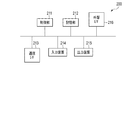
- FIG. 2 is a block diagram illustrating the software configuration of the data receiving apparatus according to the embodiment.
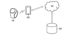
- FIG. 3 is a diagram illustrating a data transmission system including the data transmission apparatus and the data reception apparatus according to the embodiment.
- FIG. 4 is a block diagram illustrating the hardware configuration of the data receiving apparatus according to the embodiment.
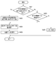
- FIG. 5 is a flowchart illustrating the operation of the data receiving apparatus according to the embodiment.
- FIG. 6 is a block diagram illustrating the software configuration of the data transmission apparatus according to the embodiment.
- FIG. 7 is a block diagram illustrating the hardware configuration of the data transmission apparatus according to the embodiment.
- FIG. 8 is a flowchart illustrating the operation of the data transmission apparatus according to the embodiment.
- FIG. 1 is a block diagram showing an application example of the data receiving apparatus according to the embodiment.
- FIG. 2 is a block diagram illustrating the software configuration of the data receiving apparatus according to the embodiment.
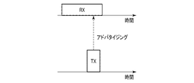
- FIG. 9 is an explanatory diagram of advertising performed in BLE.
- FIG. 10 is a diagram illustrating the data structure of a packet transmitted and received in BLE.
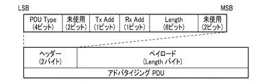
- FIG. 11 is a diagram illustrating the data structure of the PDU field of the advertisement packet.
- FIG. 12 is a diagram illustrating data stored in the payload of the PDU field of the packet received by the data receiving apparatus according to the embodiment.
- FIG. 13 is a diagram illustrating the correspondence between the local date and time on the transmitting side and the reference date and time.
- FIG. 14 is an explanatory diagram of an operation of the date and time calculation unit of the data receiving device according to the embodiment.
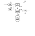
- FIG. 1 schematically shows an application example of the data receiving apparatus 200 according to the present embodiment.
- the data receiving apparatus 200 includes at least a receiving unit 201, a clock unit 202, and a date and time calculating unit 203.
- the receiving unit 201 receives a packet including date and time data indicating a local date and time in the data transmitting apparatus 100 (a packet transmission source) not shown in FIG. 1 and sensor data associated with the date and time data.
- the receiving unit 201 sends date and time data and sensor data to the date and time calculating unit 203.
- the clock unit 202 is a built-in clock of the data receiving device 200.
- the date and time calculation unit 203 converts the local date and time indicated by the received date and time data into the date and time of the clock unit 202. Specifically, the date and time calculation unit 203 can calculate the date and time of the clock unit 202 associated with the local date and time by adding the difference between the specific local date and time and the local date and time indicated by the received date and time data to the reference date and time. It is.
- the date and time calculation unit 203 can rewrite the received date and time data using the information on the reference date and time illustrated in FIG. 13.
- the data receiving apparatus 200 converts the local date and time into the date and time of its own internal clock to appropriately handle sensor data (for example, statistics Processing, display processing, etc.).
- FIG. 4 schematically illustrates an example of the hardware configuration of the data receiving apparatus 200.
- the data receiving apparatus 200 is a computer in which a control unit 211, a storage unit 212, a communication interface 213, an input device 214, an output device 215, and an external interface 216 are electrically connected.
- a control unit 211 Typically a smartphone.
- the communication interface and the external interface are described as “communication I / F” and “external I / F”, respectively.
- the control unit 211 includes a central processing unit (CPU), a random access memory (RAM), a read only memory (ROM), and the like.
- the CPU develops the program stored in the storage unit 212 in the RAM. Then, the CPU interprets and executes this program, whereby the control unit 211 can execute various information processing, for example, the processing of the functional block described in the item of the software configuration.
- the storage unit 212 is a so-called auxiliary storage device, and may be, for example, a semiconductor memory such as a built-in or external flash memory.
- the storage unit 212 stores a program executed by the control unit 211, data used by the control unit 211 (for example, an identifier, date and time data, sensor data), and the like.
- data used by the control unit 211 for example, an identifier, date and time data, sensor data
- the storage unit 212 may be a hard disk drive (HDD), a solid state drive (SSD), or the like.
- the communication interface 213 is mainly various wireless communication modules for BLE, mobile communication (3G, 4G, etc.), wireless LAN (Local Area Network), etc., and is an interface for performing wireless communication via a network. is there.
- the communication interface 213 may further include a wired communication module such as a wired LAN module.
- the input device 214 is a device for receiving user input (user operation information) such as a touch screen, a keyboard, a mouse, and the like.
- the output device 215 is, for example, a device for performing an output such as a display or a speaker.
- the external interface 216 is a USB (Universal Serial Bus) port, a memory card slot, or the like, and is an interface for connecting to an external device.
- USB Universal Serial Bus
- the control unit 211 may include a plurality of processors.
- the data reception device 200 may be configured by a plurality of information processing devices.
- a general-purpose desktop PC Personal Computer
- a tablet PC or the like may be used in addition to the information processing apparatus designed specifically for the service to be provided.
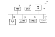
- FIG. 7 schematically illustrates an example of the hardware configuration of the data transmission apparatus 100.
- the control unit 111, the storage unit 112, the communication interface 113, the input device 114, the output device 115, the external interface 116, and the battery 117 are electrically connected. It is a connected computer, typically a sensor device that routinely measures the amount of biological information or activity information of the user, such as a sphygmomanometer, thermometer, activity meter, pedometer, body composition meter, weight scale and the like.
- the communication interface and the external interface are described as “communication I / F” and “external I / F”, respectively.
- the control unit 111 includes a CPU, a RAM, a ROM, and the like.
- the CPU develops the program stored in the storage unit 112 in the RAM. Then, the CPU interprets and executes this program, whereby the control unit 111 can execute various information processing, for example, processing of the functional blocks described in the item of the software configuration.
- the storage unit 112 is a so-called auxiliary storage device, and may be, for example, a semiconductor memory such as a built-in or external flash memory, an HDD, or an SSD.
- the storage unit 112 stores a program executed by the control unit 111, data used by the control unit 111 (for example, date and time data and sensor data), and the like.
- the communication interface 113 includes at least a wireless module capable of one-way communication such as BLE.
- the input device 114 includes, for example, a device for receiving user input such as a touch screen, a button, a switch, and a sensor for detecting an amount related to biological information or activity information of the user.
- the output device 115 is, for example, a device for performing output such as a display and a speaker.
- the external interface 116 is a USB port, a memory card slot, or the like, and is an interface for connecting to an external device.
- the battery 117 supplies the power supply voltage of the data transmission apparatus 100.
- the battery 117 may be replaceable. It is not essential that the data transmission apparatus 100 is battery-powered, and may be connectable to a commercial power supply via an AC (Alternating Current) adapter. In this case, the battery 117 can be omitted.
- AC Alternating Current
- control unit 111 may include a plurality of processors.
- the data transmission device 100 may be configured by a plurality of sensor devices.
- FIG. 2 schematically shows an example of the software configuration of the data receiving apparatus 200. As shown in FIG.
- the control unit 211 illustrated in FIG. 4 develops the program stored in the storage unit 212 in the RAM. Then, the control unit 211 interprets and executes this program by the CPU to control various hardware elements shown in FIG.
- the data receiving apparatus 200 includes the receiving unit 201, the clock unit 202, the date and time calculating unit 203, the data managing unit 204, the data storage unit 205, and the transmitting unit 206. Act as a computer.
- the receiving unit 201 receives, from the data transmitting apparatus 100, a packet including sensor data and date and time data associated with the sensor data.
- This packet is, for example, an advertisement packet in BLE.
- BLE may be replaced with other low power consumption / one-way communication standards in the future. In that case, the following description may be read appropriately.
- a new node periodically transmits an advertisement packet that makes itself known.
- the new node can save power consumption by entering a low power consumption sleep state after transmitting an advertisement packet once and before transmitting it.
- the receiving side of the advertisement packet since the receiving side of the advertisement packet also operates intermittently, the power consumption for transmitting and receiving the advertisement packet is small.
- FIG. 10 shows the basic structure of the BLE wireless communication packet.
- the BLE wireless communication packet has a 1-byte preamble, a 4-byte access address, a 2-39-byte (variable) protocol data unit (PDU), and a 3-byte cyclic redundancy check (CRC: Cyclic). And Redundancy Checksum).
- the length of the BLE wireless communication packet is 10 to 47 bytes, depending on the length of the PDU.
- the preamble field is prepared for synchronization of BLE wireless communication, and stores "01" or "10" repetitions.
- the access address is a fixed numerical value in the advertising channel and a random access address in the data channel.
- an advertisement packet which is a BLE wireless communication packet transmitted on an advertising channel, is targeted.
- the CRC field is used to detect a reception error.
- the calculation range of CRC is only the PDU field.
- the PDU field of the advertisement packet will be described using FIG.
- the PDU field of the data communication packet which is a BLE wireless communication packet transmitted on the data channel has a data structure different from that of FIG. 11, this embodiment does not cover the data communication packet, and therefore, the description thereof is omitted.
- the PDU field of the advertisement packet includes a 2-byte header and a payload of 0 to 37 bytes (variable).
- the header further includes a 4-bit PDU Type field, a 2-bit unused field, a 1-bit TxAdd field, a 1-bit RxAdd field, a 6-bit Length field, and a 2-bit unused field. Including.
- the PDU Type field stores a value indicating the type of this PDU.
- TxAdd field a flag indicating whether or not there is a transmission address in the payload is stored.
- RxAdd field a flag indicating whether or not there is a reception address in the payload is stored.
- Length field a value indicating the byte size of the payload is stored.
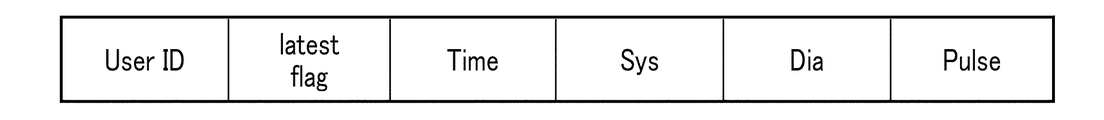
- the payload can store any data. Therefore, the data transmitting apparatus 100 stores sensor data and date and time data in the payload, using a data structure as illustrated in FIG. 12, for example.
- the data structure of FIG. 12 can be used to transmit one user's blood pressure and pulse dose sensor data.
- the data structure of FIG. 12 may be modified to transmit sensor data of a plurality of blood pressure and pulse of one user.
- the User ID field stores an identifier for identifying a user. Note that, instead of or in addition to the identifier of the user, an identifier that specifies the data transmission device 100 or the data reception device 200 may be stored.
- the latest flag is a flag (information for more generalization) indicating whether date and time data stored in the subsequent Time field can be used for date and time association. If this flag is TRUE, it is possible to associate the local date and time indicated by the date and time data stored in the Time field with the current date and time of the clock unit 202.
- the Time field stores date and time data.
- the Sys, Dia and Pulse fields store systolic blood pressure, diastolic blood pressure and pulse rate data associated with date and time data, respectively.
- the sensor data associated with the date and time data is not limited to one type, and may be a plurality of types.
- the receiving unit 201 extracts, for example, the payload of the PDU from the advertisement packet of BLE. Then, if the value of the User ID field in FIG. 12 is inappropriate (for example, it does not match the value of its own user), the receiving unit 201 may discard the received packet. On the other hand, if the value of the User ID field in FIG. 12 is appropriate (matches the value of the user of the user), the receiving unit 201 determines the flag stored in the latest flag and the date and time data stored in the Time field. The sensor data stored in the Sys, Dia, and Pulse fields are sent to the date and time calculation unit 203.
- the clock unit 202 instructs a date and time.
- the clock unit 202 includes, for example, a crystal oscillator that vibrates at a fixed frequency, a divider circuit that divides its output to obtain a 1 Hz signal, and a counter that counts this signal to obtain a serial value indicating date and time.
- the clock unit 202 may be automatically corrected based on data from a base station to which the data receiving apparatus 200 is connected.
- the date and time calculation unit 203 receives a flag, date and time data, and sensor data from the reception unit 201. If the flag indicates that date and time data can be used to associate date and time, the date and time calculation unit 203 associates the current date and time indicated by the clock unit 202 with the local date and time indicated by the date and time data as a reference date and time (see FIG. 13). ).
- the subsequent implementation may be omitted.
- the difference between the two may be accumulated to cause a large error. From the viewpoint of preventing the accumulation of such errors, it is recommended to reset the association between the reference date and time and the local date and time of the data transmission apparatus 100 as appropriate.
- this date and time data can not be associated because it is too old compared to the current date and time indicated by the clock unit 202.
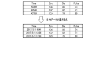
- the date and time calculation unit 203 calculates the difference between the local date and time indicated by the date and time data and the local date and time associated with the reference date and time. Then, the date and time calculation unit 203 adds the difference to the reference date and time to calculate the date and time of the clock unit 202 associated with the local date and time indicated by the date and time data. The date and time calculation unit 203 rewrites the date and time data according to the calculated date and time (see FIG. 14). The date and time calculation unit 203 sends the date and time data after rewriting and the sensor data to the data management unit 204.
- the date and time calculation unit 203 can not rewrite the date and time until the reference date and time and the local date and time of the data transmission apparatus 100 are associated with each other. In order to perform such association, it is necessary to have the data transmitting apparatus 100 transmit (almost recent) date and time data that can be used for associating date and time, and the data receiving apparatus 200 needs to receive this. Therefore, several triggers are prepared to transmit the date and time data that can be used to associate the date and time with the data transmitting apparatus 100.
- the data transmitting apparatus 100 measures the amount related to the biometric information of the user and stores the substantially latest date and time data corresponding to the measurement date and time of the sensor data in the advertisement packet of BLE immediately after the new sensor data is generated. May be sent.
- the data transmitting apparatus 100 may store substantially the latest date and time data in the advertisement packet of BLE and transmit it.
- the data transmission apparatus 100 may store the almost latest date and time data in the advertisement packet of BLE and transmit it using battery exchange as a trigger.
- the data transmitting apparatus 100 may store substantially the latest date and time data in the advertisement packet of BLE and transmit it at a predetermined cycle (for example, every day, every week, etc.).
- the data receiving apparatus 200 may output text, images or sounds prompting user input.
- the data management unit 204 receives the date and time data and the sensor data from the date and time calculation unit 203, associates the date and time data with the sensor data, and writes them in the data storage unit 205. Further, the data management unit 204 reads a set of date and time data and sensor data stored in the data storage unit 205 according to, for example, an instruction from a higher-level application (for example, a management application of biometric data) not shown. Not sent to the display unit.
- a higher-level application for example, a management application of biometric data
- the data storage unit 205 is read and written by the data management unit 204 as a set of date and time data and sensor data.
- the transmission unit 206 receives the set of date and time data and sensor data from the data management unit 204, and transmits these to the server 300 via the network (see FIG. 3).
- the transmission unit 206 uses, for example, mobile communication or WLAN.
- the appearance of the wristwatch type wearable sphygmomanometer is shown as the data transmission device 100 in the example of FIG. 3, the appearance of the data transmission device 100 is not limited to this and may be a stationary type sphygmomanometer. , May be a sensor device that measures quantities related to other biometric information or activity information.
- the server 300 corresponds to a database that manages sensor data (mainly biometric data) of a large number of users.
- the server 300 responds to, for example, access from a health leader, an insurance company or a program operator's PC, etc., to provide for user health guidance, insurance participation assessment, performance evaluation of a health promotion program, etc.
- the biometric data of the user may be transmitted.
- FIG. 6 schematically illustrates an example of the software configuration of the data transmission apparatus 100.
- the control unit 111 illustrated in FIG. 7 develops the program stored in the storage unit 112 in the RAM. Then, the control unit 111 causes the CPU to interpret and execute this program to control various hardware elements shown in FIG.
- the data transmission apparatus 100 includes the biometric sensor 101, the motion sensor 102, the clock unit 103, the input unit 104, the data management unit 105, the data storage unit 106, and transmission control.
- the computer functions as a computer including the unit 107, the transmission unit 108, the display control unit 109, and the display unit 110.
- the biometric sensor 101 obtains biometric data by measuring the amount of biometric information of the user.
- the operation of the biological sensor 101 is controlled by, for example, a sensor control unit (not shown).
- the biometric sensor 101 associates the biometric data with date and time data received from the clock unit 103 and sends the data to the data management unit 105.
- the biometric sensor 101 typically includes a blood pressure sensor that obtains blood pressure data by measuring the user's blood pressure.
- the biological data includes blood pressure data.
- Blood pressure data may include, but is not limited to, for example, systolic and diastolic blood pressure values and pulse rate.
- biological data can include electrocardiogram data, pulse wave data, body temperature data, and the like.
- the blood pressure sensor can include a blood pressure sensor (hereinafter, referred to as a continuous blood pressure sensor) capable of continuously measuring the blood pressure of the user for each beat.
- the continuous blood pressure sensor may continuously measure the blood pressure of the user from pulse wave transit time (PTT), or may realize continuous measurement by tonometry or other techniques.
- PTT pulse wave transit time
- the blood pressure sensor may include a non-continuously measurable blood pressure sensor (hereinafter referred to as a non-continuous blood pressure sensor) in place of or in addition to the continuous blood pressure sensor.
- a non-continuous blood pressure sensor measures the user's blood pressure using, for example, a cuff as a pressure sensor (oscillometric method).
- Non-continuous blood pressure sensors tend to have higher measurement accuracy than continuous blood pressure sensors. Therefore, the blood pressure sensor is replaced with the continuous blood pressure sensor, for example, triggered by that some condition is satisfied (for example, the user's blood pressure data measured by the continuous blood pressure sensor suggested a predetermined state) By operating the non-continuous blood pressure sensor, blood pressure data may be measured with higher accuracy.
- the motion sensor 102 may be, for example, an acceleration sensor or a gyro sensor.
- the motion sensor 102 obtains acceleration / angular velocity data of three axes by detecting the acceleration / angular velocity received by the motion sensor 102.
- the operation of the motion sensor 102 is controlled by, for example, a sensor control unit (not shown).
- This acceleration / angular velocity data can be used to estimate the activity state (posture and / or motion) of the user wearing the data transmission device 100.
- the motion sensor 102 associates the acceleration / angular velocity data with date and time data received from the clock unit 103 and sends the data to the data management unit 105.
- the biometric sensor 101 and the motion sensor 102 may be omitted.
- an environment sensor may be provided.
- the environmental sensor may include, for example, a temperature sensor, a humidity sensor, an air pressure sensor, and the like. That is, the sensor data may be any data that the sensor measures a predetermined physical quantity and generates based on the measurement result.
- the clock unit 103 instructs a date and time.
- the clock unit 103 includes, for example, a crystal oscillator oscillating at a fixed frequency, a divider circuit that divides its output to obtain a 1 Hz signal, and a counter that counts this signal to obtain a serial value indicating date and time. .
- the clock unit 103 sends date and time data (for example, the above-described serial value) indicating the current date and time to the biological sensor 101 and the motion sensor 102. Date and time data can be used as measurement date and time of biological data by the biometric sensor 101, measurement date and time of acceleration / angular velocity data by the motion sensor 102, and the like.
- date and time data is referred to by the display control unit 109 for display on the display unit 110 or whether the date and time data stored in the above-mentioned Time field can be used for associating the date and time (almost latest) Are referred to by the transmission control unit 107 in order to set a flag representing H or to advertise (almost recent) date and time data that can be used for date and time association.
- the clock unit 103 (the serial value held by the clock unit 103) may be designed to be adjustable (time setting) by user input, for example.
- the data receiving apparatus 200 corrects the local date and time of the data transmitting apparatus 100. Regardless of the date / time data can be rewritten as appropriate. Therefore, the input device 114 may be simplified (eg, the number of buttons can be reduced) by not using such a design. Also in this case, it is possible to present the user with a relative date and time based on the current date and time such as "10 minutes ago", "2 hours ago”, “yesterday”, "1 week ago”, etc. It is.
- the input unit 104 receives user input.
- the user input is, for example, for controlling data transmission by the transmitting unit 108, for controlling data display by the display unit 110, or starts measurement by the biological sensor 101 or the motion sensor 102. It is for.
- the user input for controlling the data transmission by the transmission unit 108 may be, for example, one that explicitly or implicitly instructs transmission of a specific set of date and time data and sensor data, which can be used for date and time association (almost recent) ) It may be such as explicitly or implicitly instructing transmission of date and time data.
- the input unit 104 transmits a user input for controlling data transmission by the transmission unit 108 to the transmission control unit 107, and transmits a user input for controlling data display by the display unit 110 to the display control unit 109.
- the user input for starting measurement by the motion sensor 102 is sent to a sensor control unit (not shown).
- the data management unit 105 receives sensor data (biological data or acceleration / angular velocity data) associated with date and time data from the biometric sensor 101 or the motion sensor 102, and writes these in the data storage unit 106.
- sensor data biological data or acceleration / angular velocity data
- the data management unit 105 may automatically send them to the transmission control unit 107 or the display control unit 109.
- the data management unit 105 uses a command from the transmission control unit 107 or the display control unit 109 as a trigger to read a set of date and time data and sensor data stored in the data storage unit 106, and transmit control unit 107 or display control. It may be sent to the part 109.
- the data storage unit 106 has the data management unit 105 read and write sets of date and time data and sensor data.
- the transmission control unit 107 receives a set of date and time data and sensor data from the data management unit 105, and generates an advertisement packet of BLE as described with reference to FIGS. 10 to 12 based on these.
- the transmission control unit 107 refers to the date and time data held by the clock unit 103 in order to set a flag indicating whether the date and time data stored in the aforementioned Time field can be used for associating a date and time. It may be compared with date and time data received from the data management unit 105. Also, the transmission control unit 107 receives (almost recent) date and time data that can be used to associate date and time from the clock unit 103, and based on this, advertises date and time data that can be used to associate date and time to the data receiving apparatus 200. It is also possible to generate an advertisement packet to The transmission control unit 107 sends the generated advertisement packet to the transmission unit 108.
- the transmission control unit 107 may receive from the input unit 104 a user input for controlling data transmission by the transmission unit 108.
- the transmission control unit 107 requests the data management unit 105 to set a specific date and time data and sensor data based on a user input, or the clock unit 103 is substantially up-to-date (available for date and time association) Request date and time data of
- the transmission control unit 107 can generate an advertisement packet regardless of user input, for retransmission of data transmitted in the past, advertising of date and time data usable for associating date and time, and the like.
- the transmitting unit 108 receives an advertisement packet of BLE from the transmission control unit 107, and transmits (advertises) this.
- the display control unit 109 receives a set of date and time data and sensor data from the data management unit 105, and generates display data of the display unit 110 based on these.
- the display control unit 109 may also generate display data for causing the display unit 110 to display date and time data held by the clock unit 103 with reference to the clock unit 103.
- the display control unit 109 sends the generated display data to the display unit 110.
- the display control unit 109 may receive, from the input unit 104, a user input for controlling data display by the display unit 110. In this case, the display control unit 109 requests the data management unit 105 to set a specific date and time data and sensor data based on a user input, and requests the clock unit 103 to obtain substantially latest date and time data.
- the display unit 110 receives display data from the display control unit 109 and displays the display data.
- each function of the data transmission device 100 and the data reception device 200 is realized by a general-purpose CPU.
- some or all of the above functions may be realized by one or more dedicated processors.
- the software configurations of the data transmitting apparatus 100 and the data receiving apparatus 200 omission, replacement, and addition of functions may be performed as appropriate according to the embodiment.
- FIG. 5 is a flowchart illustrating an example of the operation of the data receiving apparatus 200.
- the process sequence demonstrated below is only an example, and each process may be changed as much as possible.
- steps may be omitted, replaced, or added as appropriate, according to the embodiment.
- the date and time calculation unit 203 refers to the flag received by the reception unit 201, and determines whether the date and time data stored in the advertisement packet can be used for associating date and time (step S401). If the advertisement packet includes available date and time data for date and time association, the process proceeds to step S402, otherwise the process proceeds to step S403.
- step S402 the date and time calculation unit 203 resets the association between the reference date and time and the local date and time of the data transmission apparatus 100. That is, the current date and time instructed by the clock unit 202 is associated with the local date and time indicated by the received date and time data as the reference date and time. Then, the process proceeds to step S404.
- step S403 the date and time calculation unit 203 determines whether the date and time have been associated, that is, whether the reference date and time and the local date and time of the data transmitting apparatus 100 have been associated in the past. If the reference date and time and the local date and time of the data transmitting apparatus 100 have been associated in the past, the process proceeds to step S404, otherwise the process proceeds to step S406.
- step S404 the date and time calculation unit 203 rewrites the received date and time data using the association between the reference date and time and the local date and time of the data transmission apparatus 100. Specifically, the date and time calculation unit 203 calculates the difference between the local date and time indicated by the received date and time data and the local date and time associated with the reference date and time. Then, the date and time calculation unit 203 adds the difference to the reference date and time to calculate the date and time of the clock unit 202 associated with the local date and time indicated by the date and time data. The date and time calculation unit 203 rewrites the date and time data according to the calculated date and time. Then, the process proceeds to step S405.
- step S405 the data management unit 204 associates the date and time data rewritten in step S404 with the received sensor data, and stores the data in the data storage unit 205, and the process ends.
- step S406 since the association between the reference date and time and the local date and time of the data transmitting apparatus 100 can not be used, the date and time calculation unit 203 can not rewrite the received date and time data. Therefore, predetermined error processing is performed, and the process ends.
- This error processing causes the output device 215 of the data receiving apparatus 200 to output, for example, a text, an image or a voice prompting a user to be a trigger for advertising the date and time data usable for associating date and time to the data transmitting apparatus 100. Can be included.
- the received date and time data and sensor data may be discarded or saved. If the received date and time data and sensor data are stored, data loss is prevented by rewriting the date and time data using the association between the reference date and time that will be performed thereafter and the local date and time of the data transmission apparatus 100. be able to.
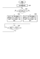
- FIG. 8 is a flowchart illustrating an example of the operation of the data transmission apparatus 100.
- the process sequence demonstrated below is only an example, and each process may be changed as much as possible.
- steps may be omitted, replaced, or added as appropriate, according to the embodiment.
- the operation example of FIG. 8 is started by the sensor control unit (not shown) giving a command to the living body sensor 101 to start measurement.
- the data transmitting apparatus 100 advertises BLE date / time data (which can be used to associate date and time) of the clock unit 103 according to various predetermined triggers, not limited to the operation example of FIG. 8. It can be stored in a mentment packet and sent.
- the substantially latest date and time data may be transmitted in association with the sensor data, or may be transmitted independently of the sensor data.
- the biometric sensor 101 measures the amount of biometric information of the user to generate biometric data (sensor data) (step S501).
- the biometric data is sent to the data management unit 105 in association with date and time data of the clock unit 103.
- the data management unit 105 writes the set of date and time data and biometric data to the data storage unit 106 and sends it to the transmission control unit 107 for advertising. Then, the process proceeds to step S502.
- step S502 the transmission control unit 107 compares the date and time indicated by the date and time data to be advertised with the current date and time of the clock unit 103, and determines whether a predetermined time has elapsed. If the predetermined time has elapsed, the process proceeds to step S504; otherwise, the process proceeds to step S503.
- the predetermined time increases, the accuracy of the association between the reference date and time in the data receiving apparatus 200 and the local date and time of the data transmitting apparatus 100 decreases (ie, the tolerance increases), but the frequency of association is increased.
- the predetermined time may be set to several seconds to several tens of seconds.
- step S503 the transmission control unit 107 is an advertisement packet storing a flag indicating that date and time data to be advertised can be used for date and time association, the date and time data, and the biometric data measured in step S501.
- the transmission unit 108 transmits this. Then, the process proceeds to step S505.
- step S504 the transmission control unit 107 is an advertisement that stores a flag indicating that date and time data to be advertised can not be used for associating date and time, the date and time data, and biometric data measured in step S501.
- the packet is generated, and the transmitting unit 108 transmits (advertises) this. Then, the process proceeds to step S505.
- step S505 the retransmission timing of the advertisement packet transmitted in step S503 or step S504 is awaited.
- the source can not confirm whether the transmission data has been correctly received by the destination, so it is possible to retransmit the data on the assumption of data loss at the destination. preferable.
- the process returns to step S502.
- a flag indicating that date and time data to be advertised can be used for associating date and time until a predetermined time elapses from the measurement of the amount related to biological information (step S501) Advertisement packets are sent repeatedly. That is, if the data receiving apparatus 200 receives the advertisement packet before the predetermined time elapses, the reference date and time can be associated with the local date and time of the data transmitting apparatus 100.
- the data transmission apparatus includes one-way communication including date and time data indicating a date and time that is substantially latest (available for date and time association) of the clock unit in response to a predetermined trigger.
- the data receiving apparatus associates the date and time indicated by the date and time data transmitted from the data transmitting apparatus with the current date and time (reference date and time) of the clock unit contained therein.
- the data receiving device rewrites the local date and time of the data transmitting device indicated by the date and time data associated with the sensor data transmitted from the data transmitting device, based on the date and time instructed by the clock unit incorporated therein. Therefore, according to the present embodiment, the data reception device can not detect sensor data even when time setting of the clock unit incorporated in the data transmission device is not performed or when the clock unit indicates an incorrect date and time. The appropriate date and time associated with can be calculated.
- the data transmission apparatus stores and transmits sensor data and date and time data indicating the measurement date and time of the sensor data in an advertisement packet of BLE.
- the data transmitting apparatus may store date and time difference data indicating an elapsed date and time from the measurement date and time in the advertisement packet of BLE and transmit.
- the date and time difference data can be derived, for example, by calculating the difference between the (measurement) date and time indicated by the date and time data associated with the sensor data and the date and time substantially latest (that is, at the time of packet transmission) of the clock unit 103 is there.
- the data receiving apparatus calculates date and time data from the date and time difference data using the substantially latest date and time of the clock unit 202.
- the date and time calculation unit 203 can calculate the date and time associated with the sensor data by subtracting the difference indicated by the date and time difference data from the substantially latest date and time of the clock unit 202.
- a data receiving apparatus for communicating with a data transmitting apparatus comprising: With memory A processor connected to the memory; The processor is (A) a clock unit that indicates the date and time; (B) a receiving unit for receiving a packet for one-way communication transmitted from the data transmitting apparatus; (C) (1) When the packet includes first date and time data indicating a local date and time in the data transmission apparatus, and information indicating that the first date and time data can be used for date and time association.
- a processor connected to the memory;
- the processor is (A) a clock unit that indicates the date and time; (B) (1) A first one for one-way communication, including first date and time data indicating date and time of the clock unit and information indicating that the first date and time data can be used for date and time association.
- a second packet for one-way communication including: (a) the packet, (2) sensor data measured by the sensor, and second date and time data indicating the date and time of the clock unit when the sensor data is measured; Configured to act as a transmitter to transmit Data transmission device.
- a data receiving apparatus for communicating with a data transmitting apparatus, the data receiving apparatus comprising: With memory A processor connected to the memory; The processor is (A) a clock unit that indicates the date and time; (B) a receiving unit for receiving a packet for one-way communication transmitted from the data transmitting apparatus; (C) When the packet includes sensor data and date / time difference data associated with the sensor data, date / time data representing the measurement date / time of the sensor data from the date / time difference data using the date / time of the clock unit It is configured to function as a calculation unit to calculate The date and time difference data indicates the difference between the local date and time when the transmission source of the packet measured the sensor data associated with the date and time difference data and the local date and time when the transmission source of the packet transmitted the packet. Data receiver.
- the processor is (A) a clock unit that indicates the date and time; (B) is configured to function as a transmitter that transmits a packet for one-way communication;
- the packet includes sensor data measured by a sensor and date / time difference data indicating a difference between a date and time of the clock unit when the sensor data is measured and a date and time of the clock unit when the packet is transmitted.
- Data transmission device is (A) a clock unit that indicates the date and time; (B) is configured to function as a transmitter that transmits a packet for one-way communication;
- the packet includes sensor data measured by a sensor and date / time difference data indicating a difference between a date and time of the clock unit when the sensor data is measured and a date and time of the clock unit when the packet is transmitted.
Landscapes
- Engineering & Computer Science (AREA)
- Health & Medical Sciences (AREA)
- Signal Processing (AREA)
- Computer Networks & Wireless Communication (AREA)
- Life Sciences & Earth Sciences (AREA)
- Physics & Mathematics (AREA)
- Medical Informatics (AREA)
- General Health & Medical Sciences (AREA)
- General Physics & Mathematics (AREA)
- Vascular Medicine (AREA)
- Cardiology (AREA)
- Computing Systems (AREA)
- Biomedical Technology (AREA)
- Biophysics (AREA)
- Molecular Biology (AREA)
- Surgery (AREA)
- Animal Behavior & Ethology (AREA)
- Pathology (AREA)
- Public Health (AREA)
- Veterinary Medicine (AREA)
- Ophthalmology & Optometry (AREA)
- Heart & Thoracic Surgery (AREA)
- Physiology (AREA)
- Arrangements For Transmission Of Measured Signals (AREA)
- Measuring Pulse, Heart Rate, Blood Pressure Or Blood Flow (AREA)
- Small-Scale Networks (AREA)
- Telephone Function (AREA)
- Telephonic Communication Services (AREA)
- Electric Clocks (AREA)
Priority Applications (3)
| Application Number | Priority Date | Filing Date | Title |
|---|---|---|---|
| DE112018004089.5T DE112018004089B4 (de) | 2017-08-09 | 2018-08-01 | Datenempfangsvorrichtung, Datenübertragungsvorrichtung und Datenübertragungssystem |
| CN201880048283.3A CN110945574B (zh) | 2017-08-09 | 2018-08-01 | 数据接收装置、发送装置、传送系统和包的数据结构 |
| US16/747,628 US11271667B2 (en) | 2017-08-09 | 2020-01-21 | Data receiving apparatus, data transmission apparatus and data transmission system |
Applications Claiming Priority (2)
| Application Number | Priority Date | Filing Date | Title |
|---|---|---|---|
| JP2017-154762 | 2017-08-09 | ||
| JP2017154762A JP7086541B2 (ja) | 2017-08-09 | 2017-08-09 | データ受信装置、データ送信装置およびデータ伝送システム |
Related Child Applications (1)
| Application Number | Title | Priority Date | Filing Date |
|---|---|---|---|
| US16/747,628 Continuation US11271667B2 (en) | 2017-08-09 | 2020-01-21 | Data receiving apparatus, data transmission apparatus and data transmission system |
Publications (1)
| Publication Number | Publication Date |
|---|---|
| WO2019031341A1 true WO2019031341A1 (ja) | 2019-02-14 |
Family
ID=65271039
Family Applications (1)
| Application Number | Title | Priority Date | Filing Date |
|---|---|---|---|
| PCT/JP2018/028824 Ceased WO2019031341A1 (ja) | 2017-08-09 | 2018-08-01 | データ受信装置、データ送信装置およびデータ伝送システム |
Country Status (5)
| Country | Link |
|---|---|
| US (1) | US11271667B2 (enExample) |
| JP (1) | JP7086541B2 (enExample) |
| CN (1) | CN110945574B (enExample) |
| DE (1) | DE112018004089B4 (enExample) |
| WO (1) | WO2019031341A1 (enExample) |
Families Citing this family (1)
| Publication number | Priority date | Publication date | Assignee | Title |
|---|---|---|---|---|
| JP7251263B2 (ja) * | 2019-03-28 | 2023-04-04 | オムロンヘルスケア株式会社 | 測定機器 |
Citations (4)
| Publication number | Priority date | Publication date | Assignee | Title |
|---|---|---|---|---|
| JPH09305888A (ja) * | 1996-05-16 | 1997-11-28 | Casio Comput Co Ltd | 電子機器および当該電子機器を用いたシステム |
| JP2008183082A (ja) * | 2007-01-29 | 2008-08-14 | Seiko Epson Corp | 生体情報管理システム、中継装置、生体情報計測装置、中継装置の制御方法、生体情報計測装置の制御方法、中継装置の制御プログラム、及び、生体情報計測装置の制御プログラム |
| JP2008188379A (ja) * | 2007-02-08 | 2008-08-21 | Matsushita Electric Ind Co Ltd | 生体信号測定時刻修正システム |
| JP2008253480A (ja) * | 2007-04-04 | 2008-10-23 | Tanita Corp | 中継装置、中継方法、健康管理システム及びデータ管理システム |
Family Cites Families (19)
| Publication number | Priority date | Publication date | Assignee | Title |
|---|---|---|---|---|
| JPS5852620B2 (ja) | 1979-04-12 | 1983-11-24 | フロイント産業株式会社 | 代用粉乳 |
| JP3800229B2 (ja) * | 2004-09-08 | 2006-07-26 | オムロン株式会社 | 検知装置、異常監視システム、検知装置の制御プログラム、検知装置の制御プログラムを記録した記録媒体 |
| CN100342410C (zh) * | 2005-06-06 | 2007-10-10 | 重庆大学 | 无线生理信息传感器网络的时间同步方法与装置 |
| JP5169644B2 (ja) * | 2008-09-02 | 2013-03-27 | オムロンヘルスケア株式会社 | 血圧測定装置 |
| JP5200943B2 (ja) * | 2009-01-07 | 2013-06-05 | オムロンヘルスケア株式会社 | 血圧測定装置 |
| WO2010098379A1 (ja) * | 2009-02-26 | 2010-09-02 | オムロンヘルスケア株式会社 | 生体情報管理システムおよび生体情報管理方法 |
| EP2498536B1 (en) * | 2009-11-06 | 2017-01-11 | Intertrust Technologies Corporation | Communication apparatus and communication method |
| JP5569051B2 (ja) * | 2010-03-11 | 2014-08-13 | オムロンヘルスケア株式会社 | 生体情報測定装置、生体情報管理システムおよび生体情報管理方法 |
| JP5673187B2 (ja) * | 2011-02-16 | 2015-02-18 | オムロン株式会社 | 物体検知システム |
| US8738925B1 (en) | 2013-01-07 | 2014-05-27 | Fitbit, Inc. | Wireless portable biometric device syncing |
| JP5799967B2 (ja) * | 2013-03-01 | 2015-10-28 | トヨタ自動車株式会社 | データ送信装置、データ共有システム、データ共有方法、およびメッセージ交換システム |
| JP6123442B2 (ja) * | 2013-04-09 | 2017-05-10 | オムロン株式会社 | センサ装置、計測システム、および計測方法 |
| WO2014182428A1 (en) * | 2013-05-09 | 2014-11-13 | Allflex Usa, Inc. | Animal health monitoring system |
| JP5852620B2 (ja) | 2013-09-26 | 2016-02-03 | 有限会社Gh9 | 低消費電力近距離無線通信システム |
| US20150127284A1 (en) * | 2013-11-03 | 2015-05-07 | Microsoft Corporation | Sensor Data Time Alignment |
| KR20170008216A (ko) | 2014-05-23 | 2017-01-23 | 삼성전자주식회사 | 모듈형 센서 플랫폼을 가지는 조정 가능한 웨어러블 시스템 |
| CN205179369U (zh) * | 2014-11-26 | 2016-04-20 | 三星电子株式会社 | 用于与智能设备配对的可穿戴设备 |
| US9734682B2 (en) * | 2015-03-02 | 2017-08-15 | Enovate Medical, Llc | Asset management using an asset tag device |
| US20160307154A1 (en) * | 2015-04-15 | 2016-10-20 | BeWhere Inc. | Inventory management and control apparatus |
-
2017
- 2017-08-09 JP JP2017154762A patent/JP7086541B2/ja active Active
-
2018
- 2018-08-01 CN CN201880048283.3A patent/CN110945574B/zh active Active
- 2018-08-01 WO PCT/JP2018/028824 patent/WO2019031341A1/ja not_active Ceased
- 2018-08-01 DE DE112018004089.5T patent/DE112018004089B4/de active Active
-
2020
- 2020-01-21 US US16/747,628 patent/US11271667B2/en active Active
Patent Citations (4)
| Publication number | Priority date | Publication date | Assignee | Title |
|---|---|---|---|---|
| JPH09305888A (ja) * | 1996-05-16 | 1997-11-28 | Casio Comput Co Ltd | 電子機器および当該電子機器を用いたシステム |
| JP2008183082A (ja) * | 2007-01-29 | 2008-08-14 | Seiko Epson Corp | 生体情報管理システム、中継装置、生体情報計測装置、中継装置の制御方法、生体情報計測装置の制御方法、中継装置の制御プログラム、及び、生体情報計測装置の制御プログラム |
| JP2008188379A (ja) * | 2007-02-08 | 2008-08-21 | Matsushita Electric Ind Co Ltd | 生体信号測定時刻修正システム |
| JP2008253480A (ja) * | 2007-04-04 | 2008-10-23 | Tanita Corp | 中継装置、中継方法、健康管理システム及びデータ管理システム |
Also Published As
| Publication number | Publication date |
|---|---|
| DE112018004089B4 (de) | 2025-05-28 |
| US11271667B2 (en) | 2022-03-08 |
| JP2019032777A (ja) | 2019-02-28 |
| DE112018004089T5 (de) | 2020-04-23 |
| JP7086541B2 (ja) | 2022-06-20 |
| CN110945574B (zh) | 2021-07-20 |
| CN110945574A (zh) | 2020-03-31 |
| US20200153526A1 (en) | 2020-05-14 |
Similar Documents
| Publication | Publication Date | Title |
|---|---|---|
| US11171932B2 (en) | Data transmitting apparatus, data receiving apparatus, method and program | |
| US11223974B2 (en) | Data transmission apparatus and data reception apparatus | |
| US20210243581A1 (en) | Wireless device and wireless system | |
| US11271667B2 (en) | Data receiving apparatus, data transmission apparatus and data transmission system | |
| US10881296B2 (en) | Measuring device and transmission method | |
| US20200107755A1 (en) | Measuring device and transmission method | |
| US20200106571A1 (en) | Data communication system and data communication apparatus | |
| US11122015B2 (en) | Data transmitting apparatus | |
| US11317290B2 (en) | Information processing apparatus, server, and data transmission system | |
| WO2019031338A1 (ja) | 情報処理システム、データ送信装置、データ受信装置、情報処理方法及びプログラム | |
| JP6736975B2 (ja) | 生体情報測定装置、通信システム及び通信方法 | |
| CN110945919B (zh) | 信息处理装置、接收方法和存储介质 | |
| US10972200B2 (en) | Data receiving apparatus and data transmitting apparatus | |
| US20250190410A1 (en) | Measurement device, control method, and control recording medium | |
| WO2024042747A1 (ja) | 測定装置、情報端末、及び制御プログラム | |
| WO2019031343A1 (ja) | データ伝送システムとそのデータ送信装置及びデータ受信装置 |
Legal Events
| Date | Code | Title | Description |
|---|---|---|---|
| 121 | Ep: the epo has been informed by wipo that ep was designated in this application |
Ref document number: 18845241 Country of ref document: EP Kind code of ref document: A1 |
|
| 122 | Ep: pct application non-entry in european phase |
Ref document number: 18845241 Country of ref document: EP Kind code of ref document: A1 |
|
| WWG | Wipo information: grant in national office |
Ref document number: 112018004089 Country of ref document: DE |