WO2019031341A1 - データ受信装置、データ送信装置およびデータ伝送システム - Google Patents
データ受信装置、データ送信装置およびデータ伝送システム Download PDFInfo
- Publication number
- WO2019031341A1 WO2019031341A1 PCT/JP2018/028824 JP2018028824W WO2019031341A1 WO 2019031341 A1 WO2019031341 A1 WO 2019031341A1 JP 2018028824 W JP2018028824 W JP 2018028824W WO 2019031341 A1 WO2019031341 A1 WO 2019031341A1
- Authority
- WO
- WIPO (PCT)
- Prior art keywords
- date
- time
- data
- packet
- sensor
- Prior art date
Links
Images


Classifications
-
- G—PHYSICS
- G04—HOROLOGY
- G04G—ELECTRONIC TIME-PIECES
- G04G7/00—Synchronisation
- G04G7/02—Synchronisation by radio
- G04G7/023—Synchronisation by radio provided with arrangements to prevent synchronisation by interfering signals
-
- H—ELECTRICITY
- H04—ELECTRIC COMMUNICATION TECHNIQUE
- H04J—MULTIPLEX COMMUNICATION
- H04J3/00—Time-division multiplex systems
- H04J3/02—Details
- H04J3/06—Synchronising arrangements
- H04J3/0635—Clock or time synchronisation in a network
- H04J3/0638—Clock or time synchronisation among nodes; Internode synchronisation
- H04J3/0658—Clock or time synchronisation among packet nodes
- H04J3/0661—Clock or time synchronisation among packet nodes using timestamps
- H04J3/0664—Clock or time synchronisation among packet nodes using timestamps unidirectional timestamps
-
- A—HUMAN NECESSITIES
- A61—MEDICAL OR VETERINARY SCIENCE; HYGIENE
- A61B—DIAGNOSIS; SURGERY; IDENTIFICATION
- A61B5/00—Measuring for diagnostic purposes; Identification of persons
- A61B5/02—Detecting, measuring or recording pulse, heart rate, blood pressure or blood flow; Combined pulse/heart-rate/blood pressure determination; Evaluating a cardiovascular condition not otherwise provided for, e.g. using combinations of techniques provided for in this group with electrocardiography or electroauscultation; Heart catheters for measuring blood pressure
- A61B5/021—Measuring pressure in heart or blood vessels
- A61B5/022—Measuring pressure in heart or blood vessels by applying pressure to close blood vessels, e.g. against the skin; Ophthalmodynamometers
-
- G—PHYSICS
- G08—SIGNALLING
- G08C—TRANSMISSION SYSTEMS FOR MEASURED VALUES, CONTROL OR SIMILAR SIGNALS
- G08C25/00—Arrangements for preventing or correcting errors; Monitoring arrangements
-
- H—ELECTRICITY
- H04—ELECTRIC COMMUNICATION TECHNIQUE
- H04L—TRANSMISSION OF DIGITAL INFORMATION, e.g. TELEGRAPHIC COMMUNICATION
- H04L12/00—Data switching networks
- H04L12/28—Data switching networks characterised by path configuration, e.g. LAN [Local Area Networks] or WAN [Wide Area Networks]
-
- H—ELECTRICITY
- H04—ELECTRIC COMMUNICATION TECHNIQUE
- H04L—TRANSMISSION OF DIGITAL INFORMATION, e.g. TELEGRAPHIC COMMUNICATION
- H04L67/00—Network arrangements or protocols for supporting network services or applications
- H04L67/01—Protocols
- H04L67/12—Protocols specially adapted for proprietary or special-purpose networking environments, e.g. medical networks, sensor networks, networks in vehicles or remote metering networks
-
- H—ELECTRICITY
- H04—ELECTRIC COMMUNICATION TECHNIQUE
- H04M—TELEPHONIC COMMUNICATION
- H04M1/00—Substation equipment, e.g. for use by subscribers
-
- H—ELECTRICITY
- H04—ELECTRIC COMMUNICATION TECHNIQUE
- H04M—TELEPHONIC COMMUNICATION
- H04M11/00—Telephonic communication systems specially adapted for combination with other electrical systems
-
- H—ELECTRICITY
- H04—ELECTRIC COMMUNICATION TECHNIQUE
- H04W—WIRELESS COMMUNICATION NETWORKS
- H04W4/00—Services specially adapted for wireless communication networks; Facilities therefor
- H04W4/80—Services using short range communication, e.g. near-field communication [NFC], radio-frequency identification [RFID] or low energy communication
Definitions
- the present invention relates to a data receiving apparatus and a data transmitting apparatus that transmit and receive sensor data associated with date and time.
- a blood pressure monitor having a function of transferring blood pressure data to a user's portable information terminal has been put on the market.
- the portable information terminal for example, a smartphone, a tablet type terminal, or a notebook personal computer is used. By using this function, the user can list the measurement results of his / her blood pressure under various conditions on the portable information terminal.
- near field communication technology in particular Bluetooth (registered trademark) technology is typically used.
- Bluetooth communication connection
- WLAN wireless local area network
- the BLE connection requires complicated operations for the user for pairing, complicated post-pairing communication procedures, the portable information terminal needs to support BLE, only portable information terminals
- the blood pressure monitor requires high-performance hardware (processor, memory), high development / evaluation cost, large communication overhead, and is not suitable for small-capacity data transmission.
- BLE can also perform one-way communication called advertising.
- Japanese Patent No. 5852620 discloses a technique for transmitting data including arbitrary data in the margin of the data field of an advertisement packet.
- Blood pressure data is usually transferred from the sphygmomanometer to the portable information terminal in association with data indicating the measurement date and time.
- the measurement date and time is given based on the date and time indicated by the clock built in the sphygmomanometer. Therefore, if the clock built in the sphygmomanometer is deviated or the time is not set in the first place, the portable information terminal will process blood pressure data in association with an incorrect measurement date and time. Even if it is possible to detect that the measurement date and time is incorrect, if the sphygmomanometer only has a one-way transmission function, the clock incorporated in the sphygmomanometer by sending control data from a portable information terminal etc. It is also impossible to set the time.
- An object of the present invention is to provide a technology that enables the data receiving apparatus to reset the date and time to an appropriate date and time regardless of the correctness of the date and time associated with sensor data transmitted from the data transmitting apparatus. Do.
- a data transmission system comprises a data transmitter and a data receiver in communication with the data transmitter.
- the data transmitting apparatus can use a first clock unit for indicating date and time, (1) first date and time data indicating date and time of the first clock unit, and the first date and time data for associating the date and time A first packet for one-way communication, and (2) sensor data measured by the sensor and the date and time of the first clock when the sensor data is measured And a transmitter configured to transmit a second packet for one-way communication, the second packet including the second date and time data.
- the data receiving apparatus includes: a second clock unit for instructing date and time; a receiving unit for receiving the first packet and the second packet transmitted from the data transmitting apparatus; (1) the first When a packet is received, the date and time specified by the second clock unit is stored in the memory as a reference date and time in association with the date and time of the first clock unit indicated by the first date and time data, (2) When the second packet is received, the difference between the date and time stored in the memory in association with the reference date and time and the date and time indicated by the second date and time data, and the data stored in the memory And a calculator configured to calculate third date and time data based on the reference date and time.
- the data receiving apparatus can rewrite this date and time based on the date and time indicated by its own clock unit regardless of whether the date and time indicated by the second date and time data is correct or not. Further, the data receiving apparatus accumulates an error due to the difference in how the time of the clock portion advances between itself and the packet transmission source by resetting the association between the reference date and time and the date and time at the packet transmission source. You can prevent.
- the data transmitting apparatus can advertise the date and time of its own clock unit and information indicating that the date and time can be used for associating the date and time in the data receiving apparatus.
- a data receiver communicates with a data transmitter.
- the data receiving apparatus includes a clock unit for instructing a date and time, a receiving unit for receiving a packet for one-way communication transmitted from the data transmitting apparatus, and (1) the packet indicates a local date and time in the data transmitting apparatus.
- the clock unit may be associated with a local date and time indicated by the first date and time data. If the date and time to be indicated is stored in the memory as a reference date and time, and (2) the packet includes sensor data and second date and time data indicating the local date and time in the data transmitting apparatus, which is associated with the sensor data.
- the data transmitting apparatus includes: a clock unit for instructing a date, (1) first date and time data indicating the date and time of the clock unit, and the first date and time data indicating date and time The first packet for one-way communication, including information indicating that it can be used for association, and (2) sensor data measured by the sensor and the date and time of the clock when the sensor data is measured And a transmitter configured to transmit a second packet for one-way communication, the second packet including the second date and time data indicating. Therefore, the data transmitting apparatus can advertise the date and time of its own clock unit and information indicating that the date and time can be used for associating the date and time in the data receiving apparatus.
- the transmission section determines the sensor data and the date and time of the clock when the sensor data is measured. And transmitting the first packet including the first date and time data indicating that the first date and time data can be used to associate the date and time data, and the predetermined time from the measurement date and time of the sensor data Indicates that the sensor data and the second date and time data indicating the date and time of the clock unit when the sensor data is measured and the second date and time data can not be used for associating the date and time.
- the data transmission apparatus is configured to receive the sensor data, the date and time of its own clock when the sensor data is measured, and the date and time of the data reception apparatus for a predetermined time after the measurement of each sensor data.
- Information representing that it can be used for date and time association can be advertised.
- the data transmission apparatus further comprises an input unit for receiving an input of operation information of the user, and the transmission unit is triggered by a part of the operation information. Transmitting a first packet including the first date and time data indicating a date and time; Therefore, according to this data transmission device, the user can intentionally advertise the date and time of the clock unit and information indicating that the date and time can be used for associating the date and time in the data receiving device.
- the data transmission apparatus is driven by a battery, and the transmission unit includes the first date and time data indicating date and time of the clock unit triggered by replacement of the battery. Send the first packet. Therefore, when the data transmitting apparatus resets the information of its own clock unit with battery replacement and needs to reset the association of the date and time in the data receiving apparatus, the date and time of its own clock unit and its date and time are data Information that can be used for date and time association can be advertised in the receiving device.
- the sensor data is blood pressure data. Therefore, this data transmission device can be used to transfer blood pressure data.
- a data transmission system comprises a data transmitter and a data receiver in communication with the data transmitter.
- the data transmission apparatus includes a first clock unit for instructing date and time, and a transmission unit for transmitting a packet for one-way communication.
- the packet is a date indicating the difference between the sensor data measured by the sensor, the date and time of the first clock when the sensor data was measured, and the date and time of the first clock when the packet is transmitted And time difference data.
- the data receiving apparatus includes a second clock unit for instructing a date and time, a receiving unit for receiving the packet transmitted from the data transmitting apparatus, and the second clock unit when the packet is received.
- a calculation unit configured to calculate date and time data representing a measurement date and time of the sensor data from the date and time difference data using the date and time; Therefore, in this data transmission system, the data receiving apparatus can calculate the measurement date and time associated with the sensor data without associating the date and time.
- a data receiving device is in communication with a data transmitting device.
- the data receiving apparatus includes a clock unit for instructing a date and time, a receiving unit for receiving a packet for one-way communication transmitted from the data transmitting apparatus, and a time difference between the sensor data and the sensor data.
- calculating means for calculating date and time data representing a measurement date and time of the sensor data from the date and time difference data using the date and time of the clock section when including data, and the date and time difference data includes the date and time difference data
- the difference between the local date and time when the transmission source of the packet measured the associated sensor data of and the local date and time when the transmission source of the packet transmitted the packet. Therefore, the data receiving apparatus can calculate the measurement date and time associated with the sensor data without performing the date and time association described in the first aspect.
- a data transmitting apparatus includes a clock unit for indicating date and time, and a transmitting unit for transmitting a packet for one-way communication, the packet being a sensor measured by a sensor
- the data includes date and time difference data indicating a difference between the date and time of the clock unit when the sensor data is measured and the date and time of the clock unit when the packet is transmitted. Therefore, according to the data transmitting apparatus, the data receiving apparatus can calculate the measurement date and time associated with the sensor data without performing the association of the date and time described in the first aspect.
- the sensor data is blood pressure data. Therefore, this data transmission device can be used to transfer blood pressure data.
- a twelfth aspect of the present invention is a data structure of the packet used in a data receiving apparatus for receiving and processing a packet for one-way communication transmitted from a data transmitting apparatus, wherein the packet is sensor data and Data including first date and time data indicating a local date and time in the data transmission device associated with the sensor data, and information indicating whether the first date and time data can be used for date and time association;
- the receiving apparatus determines whether the first date and time data is usable for associating the date and time based on the information included in the received packet, and the first date and time data indicates the date and time In association with a local date and time indicated by the first date and time data included in the received packet, when it is determined that the first date and time data is available for association of It used the date and time of the clock unit whose serial data receiving device comprises a processing of setting the reference time and date.
- the data receiving apparatus can rewrite the local date and time based on the date and time indicated by the own clock unit regardless of the correctness of the local date and time indicated by the first date and time data.
- the data receiving apparatus accumulates errors due to the difference in how the time of the clock unit advances between itself and the packet transmission source by resetting the association between the reference date and time and the local date and time at the packet transmission source. You can prevent.
- the present invention it is possible to provide a technology that enables the data receiving apparatus to reset the date to an appropriate date and time regardless of whether the date and time associated with sensor data transmitted from the data transmitting apparatus is correct or incorrect. it can.
- FIG. 1 is a block diagram showing an application example of the data receiving apparatus according to the embodiment.
- FIG. 2 is a block diagram illustrating the software configuration of the data receiving apparatus according to the embodiment.
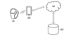
- FIG. 3 is a diagram illustrating a data transmission system including the data transmission apparatus and the data reception apparatus according to the embodiment.
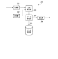
- FIG. 4 is a block diagram illustrating the hardware configuration of the data receiving apparatus according to the embodiment.
- FIG. 5 is a flowchart illustrating the operation of the data receiving apparatus according to the embodiment.
- FIG. 6 is a block diagram illustrating the software configuration of the data transmission apparatus according to the embodiment.
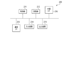
- FIG. 7 is a block diagram illustrating the hardware configuration of the data transmission apparatus according to the embodiment.
- FIG. 8 is a flowchart illustrating the operation of the data transmission apparatus according to the embodiment.
- FIG. 1 is a block diagram showing an application example of the data receiving apparatus according to the embodiment.
- FIG. 2 is a block diagram illustrating the software configuration of the data receiving apparatus according to the embodiment.
- FIG. 9 is an explanatory diagram of advertising performed in BLE.
- FIG. 10 is a diagram illustrating the data structure of a packet transmitted and received in BLE.
- FIG. 11 is a diagram illustrating the data structure of the PDU field of the advertisement packet.
- FIG. 12 is a diagram illustrating data stored in the payload of the PDU field of the packet received by the data receiving apparatus according to the embodiment.
- FIG. 13 is a diagram illustrating the correspondence between the local date and time on the transmitting side and the reference date and time.
- FIG. 14 is an explanatory diagram of an operation of the date and time calculation unit of the data receiving device according to the embodiment.
- FIG. 1 schematically shows an application example of the data receiving apparatus 200 according to the present embodiment.
- the data receiving apparatus 200 includes at least a receiving unit 201, a clock unit 202, and a date and time calculating unit 203.
- the receiving unit 201 receives a packet including date and time data indicating a local date and time in the data transmitting apparatus 100 (a packet transmission source) not shown in FIG. 1 and sensor data associated with the date and time data.
- the receiving unit 201 sends date and time data and sensor data to the date and time calculating unit 203.
- the clock unit 202 is a built-in clock of the data receiving device 200.
- the date and time calculation unit 203 converts the local date and time indicated by the received date and time data into the date and time of the clock unit 202. Specifically, the date and time calculation unit 203 can calculate the date and time of the clock unit 202 associated with the local date and time by adding the difference between the specific local date and time and the local date and time indicated by the received date and time data to the reference date and time. It is.
- the date and time calculation unit 203 can rewrite the received date and time data using the information on the reference date and time illustrated in FIG. 13.
- the data receiving apparatus 200 converts the local date and time into the date and time of its own internal clock to appropriately handle sensor data (for example, statistics Processing, display processing, etc.).
- FIG. 4 schematically illustrates an example of the hardware configuration of the data receiving apparatus 200.
- the data receiving apparatus 200 is a computer in which a control unit 211, a storage unit 212, a communication interface 213, an input device 214, an output device 215, and an external interface 216 are electrically connected.
- a control unit 211 Typically a smartphone.
- the communication interface and the external interface are described as “communication I / F” and “external I / F”, respectively.
- the control unit 211 includes a central processing unit (CPU), a random access memory (RAM), a read only memory (ROM), and the like.
- the CPU develops the program stored in the storage unit 212 in the RAM. Then, the CPU interprets and executes this program, whereby the control unit 211 can execute various information processing, for example, the processing of the functional block described in the item of the software configuration.
- the storage unit 212 is a so-called auxiliary storage device, and may be, for example, a semiconductor memory such as a built-in or external flash memory.
- the storage unit 212 stores a program executed by the control unit 211, data used by the control unit 211 (for example, an identifier, date and time data, sensor data), and the like.
- data used by the control unit 211 for example, an identifier, date and time data, sensor data
- the storage unit 212 may be a hard disk drive (HDD), a solid state drive (SSD), or the like.
- the communication interface 213 is mainly various wireless communication modules for BLE, mobile communication (3G, 4G, etc.), wireless LAN (Local Area Network), etc., and is an interface for performing wireless communication via a network. is there.
- the communication interface 213 may further include a wired communication module such as a wired LAN module.
- the input device 214 is a device for receiving user input (user operation information) such as a touch screen, a keyboard, a mouse, and the like.
- the output device 215 is, for example, a device for performing an output such as a display or a speaker.
- the external interface 216 is a USB (Universal Serial Bus) port, a memory card slot, or the like, and is an interface for connecting to an external device.
- USB Universal Serial Bus
- the control unit 211 may include a plurality of processors.
- the data reception device 200 may be configured by a plurality of information processing devices.
- a general-purpose desktop PC Personal Computer
- a tablet PC or the like may be used in addition to the information processing apparatus designed specifically for the service to be provided.
- FIG. 7 schematically illustrates an example of the hardware configuration of the data transmission apparatus 100.
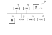
- the control unit 111, the storage unit 112, the communication interface 113, the input device 114, the output device 115, the external interface 116, and the battery 117 are electrically connected. It is a connected computer, typically a sensor device that routinely measures the amount of biological information or activity information of the user, such as a sphygmomanometer, thermometer, activity meter, pedometer, body composition meter, weight scale and the like.
- the communication interface and the external interface are described as “communication I / F” and “external I / F”, respectively.
- the control unit 111 includes a CPU, a RAM, a ROM, and the like.
- the CPU develops the program stored in the storage unit 112 in the RAM. Then, the CPU interprets and executes this program, whereby the control unit 111 can execute various information processing, for example, processing of the functional blocks described in the item of the software configuration.
- the storage unit 112 is a so-called auxiliary storage device, and may be, for example, a semiconductor memory such as a built-in or external flash memory, an HDD, or an SSD.
- the storage unit 112 stores a program executed by the control unit 111, data used by the control unit 111 (for example, date and time data and sensor data), and the like.
- the communication interface 113 includes at least a wireless module capable of one-way communication such as BLE.
- the input device 114 includes, for example, a device for receiving user input such as a touch screen, a button, a switch, and a sensor for detecting an amount related to biological information or activity information of the user.
- the output device 115 is, for example, a device for performing output such as a display and a speaker.
- the external interface 116 is a USB port, a memory card slot, or the like, and is an interface for connecting to an external device.
- the battery 117 supplies the power supply voltage of the data transmission apparatus 100.
- the battery 117 may be replaceable. It is not essential that the data transmission apparatus 100 is battery-powered, and may be connectable to a commercial power supply via an AC (Alternating Current) adapter. In this case, the battery 117 can be omitted.
- AC Alternating Current
- control unit 111 may include a plurality of processors.
- the data transmission device 100 may be configured by a plurality of sensor devices.
- FIG. 2 schematically shows an example of the software configuration of the data receiving apparatus 200. As shown in FIG.
- the control unit 211 illustrated in FIG. 4 develops the program stored in the storage unit 212 in the RAM. Then, the control unit 211 interprets and executes this program by the CPU to control various hardware elements shown in FIG.
- the data receiving apparatus 200 includes the receiving unit 201, the clock unit 202, the date and time calculating unit 203, the data managing unit 204, the data storage unit 205, and the transmitting unit 206. Act as a computer.
- the receiving unit 201 receives, from the data transmitting apparatus 100, a packet including sensor data and date and time data associated with the sensor data.
- This packet is, for example, an advertisement packet in BLE.
- BLE may be replaced with other low power consumption / one-way communication standards in the future. In that case, the following description may be read appropriately.
- a new node periodically transmits an advertisement packet that makes itself known.
- the new node can save power consumption by entering a low power consumption sleep state after transmitting an advertisement packet once and before transmitting it.
- the receiving side of the advertisement packet since the receiving side of the advertisement packet also operates intermittently, the power consumption for transmitting and receiving the advertisement packet is small.
- FIG. 10 shows the basic structure of the BLE wireless communication packet.
- the BLE wireless communication packet has a 1-byte preamble, a 4-byte access address, a 2-39-byte (variable) protocol data unit (PDU), and a 3-byte cyclic redundancy check (CRC: Cyclic). And Redundancy Checksum).
- the length of the BLE wireless communication packet is 10 to 47 bytes, depending on the length of the PDU.
- the preamble field is prepared for synchronization of BLE wireless communication, and stores "01" or "10" repetitions.
- the access address is a fixed numerical value in the advertising channel and a random access address in the data channel.
- an advertisement packet which is a BLE wireless communication packet transmitted on an advertising channel, is targeted.
- the CRC field is used to detect a reception error.
- the calculation range of CRC is only the PDU field.
- the PDU field of the advertisement packet will be described using FIG.
- the PDU field of the data communication packet which is a BLE wireless communication packet transmitted on the data channel has a data structure different from that of FIG. 11, this embodiment does not cover the data communication packet, and therefore, the description thereof is omitted.
- the PDU field of the advertisement packet includes a 2-byte header and a payload of 0 to 37 bytes (variable).
- the header further includes a 4-bit PDU Type field, a 2-bit unused field, a 1-bit TxAdd field, a 1-bit RxAdd field, a 6-bit Length field, and a 2-bit unused field. Including.
- the PDU Type field stores a value indicating the type of this PDU.
- TxAdd field a flag indicating whether or not there is a transmission address in the payload is stored.
- RxAdd field a flag indicating whether or not there is a reception address in the payload is stored.
- Length field a value indicating the byte size of the payload is stored.
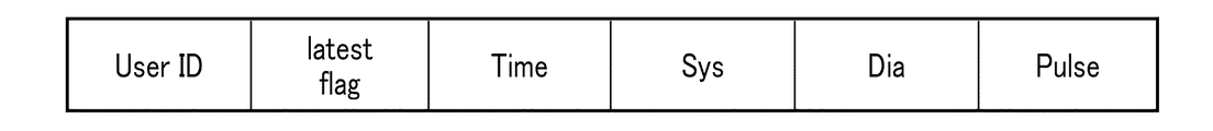
- the payload can store any data. Therefore, the data transmitting apparatus 100 stores sensor data and date and time data in the payload, using a data structure as illustrated in FIG. 12, for example.
- the data structure of FIG. 12 can be used to transmit one user's blood pressure and pulse dose sensor data.
- the data structure of FIG. 12 may be modified to transmit sensor data of a plurality of blood pressure and pulse of one user.
- the User ID field stores an identifier for identifying a user. Note that, instead of or in addition to the identifier of the user, an identifier that specifies the data transmission device 100 or the data reception device 200 may be stored.
- the latest flag is a flag (information for more generalization) indicating whether date and time data stored in the subsequent Time field can be used for date and time association. If this flag is TRUE, it is possible to associate the local date and time indicated by the date and time data stored in the Time field with the current date and time of the clock unit 202.
- the Time field stores date and time data.
- the Sys, Dia and Pulse fields store systolic blood pressure, diastolic blood pressure and pulse rate data associated with date and time data, respectively.
- the sensor data associated with the date and time data is not limited to one type, and may be a plurality of types.
- the receiving unit 201 extracts, for example, the payload of the PDU from the advertisement packet of BLE. Then, if the value of the User ID field in FIG. 12 is inappropriate (for example, it does not match the value of its own user), the receiving unit 201 may discard the received packet. On the other hand, if the value of the User ID field in FIG. 12 is appropriate (matches the value of the user of the user), the receiving unit 201 determines the flag stored in the latest flag and the date and time data stored in the Time field. The sensor data stored in the Sys, Dia, and Pulse fields are sent to the date and time calculation unit 203.
- the clock unit 202 instructs a date and time.
- the clock unit 202 includes, for example, a crystal oscillator that vibrates at a fixed frequency, a divider circuit that divides its output to obtain a 1 Hz signal, and a counter that counts this signal to obtain a serial value indicating date and time.
- the clock unit 202 may be automatically corrected based on data from a base station to which the data receiving apparatus 200 is connected.
- the date and time calculation unit 203 receives a flag, date and time data, and sensor data from the reception unit 201. If the flag indicates that date and time data can be used to associate date and time, the date and time calculation unit 203 associates the current date and time indicated by the clock unit 202 with the local date and time indicated by the date and time data as a reference date and time (see FIG. 13). ).
- the subsequent implementation may be omitted.
- the difference between the two may be accumulated to cause a large error. From the viewpoint of preventing the accumulation of such errors, it is recommended to reset the association between the reference date and time and the local date and time of the data transmission apparatus 100 as appropriate.
- this date and time data can not be associated because it is too old compared to the current date and time indicated by the clock unit 202.
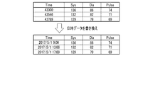
- the date and time calculation unit 203 calculates the difference between the local date and time indicated by the date and time data and the local date and time associated with the reference date and time. Then, the date and time calculation unit 203 adds the difference to the reference date and time to calculate the date and time of the clock unit 202 associated with the local date and time indicated by the date and time data. The date and time calculation unit 203 rewrites the date and time data according to the calculated date and time (see FIG. 14). The date and time calculation unit 203 sends the date and time data after rewriting and the sensor data to the data management unit 204.
- the date and time calculation unit 203 can not rewrite the date and time until the reference date and time and the local date and time of the data transmission apparatus 100 are associated with each other. In order to perform such association, it is necessary to have the data transmitting apparatus 100 transmit (almost recent) date and time data that can be used for associating date and time, and the data receiving apparatus 200 needs to receive this. Therefore, several triggers are prepared to transmit the date and time data that can be used to associate the date and time with the data transmitting apparatus 100.
- the data transmitting apparatus 100 measures the amount related to the biometric information of the user and stores the substantially latest date and time data corresponding to the measurement date and time of the sensor data in the advertisement packet of BLE immediately after the new sensor data is generated. May be sent.
- the data transmitting apparatus 100 may store substantially the latest date and time data in the advertisement packet of BLE and transmit it.
- the data transmission apparatus 100 may store the almost latest date and time data in the advertisement packet of BLE and transmit it using battery exchange as a trigger.
- the data transmitting apparatus 100 may store substantially the latest date and time data in the advertisement packet of BLE and transmit it at a predetermined cycle (for example, every day, every week, etc.).
- the data receiving apparatus 200 may output text, images or sounds prompting user input.
- the data management unit 204 receives the date and time data and the sensor data from the date and time calculation unit 203, associates the date and time data with the sensor data, and writes them in the data storage unit 205. Further, the data management unit 204 reads a set of date and time data and sensor data stored in the data storage unit 205 according to, for example, an instruction from a higher-level application (for example, a management application of biometric data) not shown. Not sent to the display unit.
- a higher-level application for example, a management application of biometric data
- the data storage unit 205 is read and written by the data management unit 204 as a set of date and time data and sensor data.
- the transmission unit 206 receives the set of date and time data and sensor data from the data management unit 204, and transmits these to the server 300 via the network (see FIG. 3).
- the transmission unit 206 uses, for example, mobile communication or WLAN.
- the appearance of the wristwatch type wearable sphygmomanometer is shown as the data transmission device 100 in the example of FIG. 3, the appearance of the data transmission device 100 is not limited to this and may be a stationary type sphygmomanometer. , May be a sensor device that measures quantities related to other biometric information or activity information.
- the server 300 corresponds to a database that manages sensor data (mainly biometric data) of a large number of users.
- the server 300 responds to, for example, access from a health leader, an insurance company or a program operator's PC, etc., to provide for user health guidance, insurance participation assessment, performance evaluation of a health promotion program, etc.
- the biometric data of the user may be transmitted.
- FIG. 6 schematically illustrates an example of the software configuration of the data transmission apparatus 100.
- the control unit 111 illustrated in FIG. 7 develops the program stored in the storage unit 112 in the RAM. Then, the control unit 111 causes the CPU to interpret and execute this program to control various hardware elements shown in FIG.
- the data transmission apparatus 100 includes the biometric sensor 101, the motion sensor 102, the clock unit 103, the input unit 104, the data management unit 105, the data storage unit 106, and transmission control.
- the computer functions as a computer including the unit 107, the transmission unit 108, the display control unit 109, and the display unit 110.
- the biometric sensor 101 obtains biometric data by measuring the amount of biometric information of the user.
- the operation of the biological sensor 101 is controlled by, for example, a sensor control unit (not shown).
- the biometric sensor 101 associates the biometric data with date and time data received from the clock unit 103 and sends the data to the data management unit 105.
- the biometric sensor 101 typically includes a blood pressure sensor that obtains blood pressure data by measuring the user's blood pressure.
- the biological data includes blood pressure data.
- Blood pressure data may include, but is not limited to, for example, systolic and diastolic blood pressure values and pulse rate.
- biological data can include electrocardiogram data, pulse wave data, body temperature data, and the like.
- the blood pressure sensor can include a blood pressure sensor (hereinafter, referred to as a continuous blood pressure sensor) capable of continuously measuring the blood pressure of the user for each beat.
- the continuous blood pressure sensor may continuously measure the blood pressure of the user from pulse wave transit time (PTT), or may realize continuous measurement by tonometry or other techniques.
- PTT pulse wave transit time
- the blood pressure sensor may include a non-continuously measurable blood pressure sensor (hereinafter referred to as a non-continuous blood pressure sensor) in place of or in addition to the continuous blood pressure sensor.
- a non-continuous blood pressure sensor measures the user's blood pressure using, for example, a cuff as a pressure sensor (oscillometric method).
- Non-continuous blood pressure sensors tend to have higher measurement accuracy than continuous blood pressure sensors. Therefore, the blood pressure sensor is replaced with the continuous blood pressure sensor, for example, triggered by that some condition is satisfied (for example, the user's blood pressure data measured by the continuous blood pressure sensor suggested a predetermined state) By operating the non-continuous blood pressure sensor, blood pressure data may be measured with higher accuracy.
- the motion sensor 102 may be, for example, an acceleration sensor or a gyro sensor.
- the motion sensor 102 obtains acceleration / angular velocity data of three axes by detecting the acceleration / angular velocity received by the motion sensor 102.
- the operation of the motion sensor 102 is controlled by, for example, a sensor control unit (not shown).
- This acceleration / angular velocity data can be used to estimate the activity state (posture and / or motion) of the user wearing the data transmission device 100.
- the motion sensor 102 associates the acceleration / angular velocity data with date and time data received from the clock unit 103 and sends the data to the data management unit 105.
- the biometric sensor 101 and the motion sensor 102 may be omitted.
- an environment sensor may be provided.
- the environmental sensor may include, for example, a temperature sensor, a humidity sensor, an air pressure sensor, and the like. That is, the sensor data may be any data that the sensor measures a predetermined physical quantity and generates based on the measurement result.
- the clock unit 103 instructs a date and time.
- the clock unit 103 includes, for example, a crystal oscillator oscillating at a fixed frequency, a divider circuit that divides its output to obtain a 1 Hz signal, and a counter that counts this signal to obtain a serial value indicating date and time. .
- the clock unit 103 sends date and time data (for example, the above-described serial value) indicating the current date and time to the biological sensor 101 and the motion sensor 102. Date and time data can be used as measurement date and time of biological data by the biometric sensor 101, measurement date and time of acceleration / angular velocity data by the motion sensor 102, and the like.
- date and time data is referred to by the display control unit 109 for display on the display unit 110 or whether the date and time data stored in the above-mentioned Time field can be used for associating the date and time (almost latest) Are referred to by the transmission control unit 107 in order to set a flag representing H or to advertise (almost recent) date and time data that can be used for date and time association.
- the clock unit 103 (the serial value held by the clock unit 103) may be designed to be adjustable (time setting) by user input, for example.
- the data receiving apparatus 200 corrects the local date and time of the data transmitting apparatus 100. Regardless of the date / time data can be rewritten as appropriate. Therefore, the input device 114 may be simplified (eg, the number of buttons can be reduced) by not using such a design. Also in this case, it is possible to present the user with a relative date and time based on the current date and time such as "10 minutes ago", "2 hours ago”, “yesterday”, "1 week ago”, etc. It is.
- the input unit 104 receives user input.
- the user input is, for example, for controlling data transmission by the transmitting unit 108, for controlling data display by the display unit 110, or starts measurement by the biological sensor 101 or the motion sensor 102. It is for.
- the user input for controlling the data transmission by the transmission unit 108 may be, for example, one that explicitly or implicitly instructs transmission of a specific set of date and time data and sensor data, which can be used for date and time association (almost recent) ) It may be such as explicitly or implicitly instructing transmission of date and time data.
- the input unit 104 transmits a user input for controlling data transmission by the transmission unit 108 to the transmission control unit 107, and transmits a user input for controlling data display by the display unit 110 to the display control unit 109.
- the user input for starting measurement by the motion sensor 102 is sent to a sensor control unit (not shown).
- the data management unit 105 receives sensor data (biological data or acceleration / angular velocity data) associated with date and time data from the biometric sensor 101 or the motion sensor 102, and writes these in the data storage unit 106.
- sensor data biological data or acceleration / angular velocity data
- the data management unit 105 may automatically send them to the transmission control unit 107 or the display control unit 109.
- the data management unit 105 uses a command from the transmission control unit 107 or the display control unit 109 as a trigger to read a set of date and time data and sensor data stored in the data storage unit 106, and transmit control unit 107 or display control. It may be sent to the part 109.
- the data storage unit 106 has the data management unit 105 read and write sets of date and time data and sensor data.
- the transmission control unit 107 receives a set of date and time data and sensor data from the data management unit 105, and generates an advertisement packet of BLE as described with reference to FIGS. 10 to 12 based on these.
- the transmission control unit 107 refers to the date and time data held by the clock unit 103 in order to set a flag indicating whether the date and time data stored in the aforementioned Time field can be used for associating a date and time. It may be compared with date and time data received from the data management unit 105. Also, the transmission control unit 107 receives (almost recent) date and time data that can be used to associate date and time from the clock unit 103, and based on this, advertises date and time data that can be used to associate date and time to the data receiving apparatus 200. It is also possible to generate an advertisement packet to The transmission control unit 107 sends the generated advertisement packet to the transmission unit 108.
- the transmission control unit 107 may receive from the input unit 104 a user input for controlling data transmission by the transmission unit 108.
- the transmission control unit 107 requests the data management unit 105 to set a specific date and time data and sensor data based on a user input, or the clock unit 103 is substantially up-to-date (available for date and time association) Request date and time data of
- the transmission control unit 107 can generate an advertisement packet regardless of user input, for retransmission of data transmitted in the past, advertising of date and time data usable for associating date and time, and the like.
- the transmitting unit 108 receives an advertisement packet of BLE from the transmission control unit 107, and transmits (advertises) this.
- the display control unit 109 receives a set of date and time data and sensor data from the data management unit 105, and generates display data of the display unit 110 based on these.
- the display control unit 109 may also generate display data for causing the display unit 110 to display date and time data held by the clock unit 103 with reference to the clock unit 103.
- the display control unit 109 sends the generated display data to the display unit 110.
- the display control unit 109 may receive, from the input unit 104, a user input for controlling data display by the display unit 110. In this case, the display control unit 109 requests the data management unit 105 to set a specific date and time data and sensor data based on a user input, and requests the clock unit 103 to obtain substantially latest date and time data.
- the display unit 110 receives display data from the display control unit 109 and displays the display data.
- each function of the data transmission device 100 and the data reception device 200 is realized by a general-purpose CPU.
- some or all of the above functions may be realized by one or more dedicated processors.
- the software configurations of the data transmitting apparatus 100 and the data receiving apparatus 200 omission, replacement, and addition of functions may be performed as appropriate according to the embodiment.
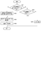
- FIG. 5 is a flowchart illustrating an example of the operation of the data receiving apparatus 200.
- the process sequence demonstrated below is only an example, and each process may be changed as much as possible.
- steps may be omitted, replaced, or added as appropriate, according to the embodiment.
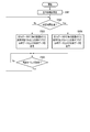
- the date and time calculation unit 203 refers to the flag received by the reception unit 201, and determines whether the date and time data stored in the advertisement packet can be used for associating date and time (step S401). If the advertisement packet includes available date and time data for date and time association, the process proceeds to step S402, otherwise the process proceeds to step S403.
- step S402 the date and time calculation unit 203 resets the association between the reference date and time and the local date and time of the data transmission apparatus 100. That is, the current date and time instructed by the clock unit 202 is associated with the local date and time indicated by the received date and time data as the reference date and time. Then, the process proceeds to step S404.
- step S403 the date and time calculation unit 203 determines whether the date and time have been associated, that is, whether the reference date and time and the local date and time of the data transmitting apparatus 100 have been associated in the past. If the reference date and time and the local date and time of the data transmitting apparatus 100 have been associated in the past, the process proceeds to step S404, otherwise the process proceeds to step S406.
- step S404 the date and time calculation unit 203 rewrites the received date and time data using the association between the reference date and time and the local date and time of the data transmission apparatus 100. Specifically, the date and time calculation unit 203 calculates the difference between the local date and time indicated by the received date and time data and the local date and time associated with the reference date and time. Then, the date and time calculation unit 203 adds the difference to the reference date and time to calculate the date and time of the clock unit 202 associated with the local date and time indicated by the date and time data. The date and time calculation unit 203 rewrites the date and time data according to the calculated date and time. Then, the process proceeds to step S405.
- step S405 the data management unit 204 associates the date and time data rewritten in step S404 with the received sensor data, and stores the data in the data storage unit 205, and the process ends.
- step S406 since the association between the reference date and time and the local date and time of the data transmitting apparatus 100 can not be used, the date and time calculation unit 203 can not rewrite the received date and time data. Therefore, predetermined error processing is performed, and the process ends.
- This error processing causes the output device 215 of the data receiving apparatus 200 to output, for example, a text, an image or a voice prompting a user to be a trigger for advertising the date and time data usable for associating date and time to the data transmitting apparatus 100. Can be included.
- the received date and time data and sensor data may be discarded or saved. If the received date and time data and sensor data are stored, data loss is prevented by rewriting the date and time data using the association between the reference date and time that will be performed thereafter and the local date and time of the data transmission apparatus 100. be able to.
- FIG. 8 is a flowchart illustrating an example of the operation of the data transmission apparatus 100.
- the process sequence demonstrated below is only an example, and each process may be changed as much as possible.
- steps may be omitted, replaced, or added as appropriate, according to the embodiment.
- the operation example of FIG. 8 is started by the sensor control unit (not shown) giving a command to the living body sensor 101 to start measurement.
- the data transmitting apparatus 100 advertises BLE date / time data (which can be used to associate date and time) of the clock unit 103 according to various predetermined triggers, not limited to the operation example of FIG. 8. It can be stored in a mentment packet and sent.
- the substantially latest date and time data may be transmitted in association with the sensor data, or may be transmitted independently of the sensor data.
- the biometric sensor 101 measures the amount of biometric information of the user to generate biometric data (sensor data) (step S501).
- the biometric data is sent to the data management unit 105 in association with date and time data of the clock unit 103.
- the data management unit 105 writes the set of date and time data and biometric data to the data storage unit 106 and sends it to the transmission control unit 107 for advertising. Then, the process proceeds to step S502.
- step S502 the transmission control unit 107 compares the date and time indicated by the date and time data to be advertised with the current date and time of the clock unit 103, and determines whether a predetermined time has elapsed. If the predetermined time has elapsed, the process proceeds to step S504; otherwise, the process proceeds to step S503.
- the predetermined time increases, the accuracy of the association between the reference date and time in the data receiving apparatus 200 and the local date and time of the data transmitting apparatus 100 decreases (ie, the tolerance increases), but the frequency of association is increased.
- the predetermined time may be set to several seconds to several tens of seconds.
- step S503 the transmission control unit 107 is an advertisement packet storing a flag indicating that date and time data to be advertised can be used for date and time association, the date and time data, and the biometric data measured in step S501.
- the transmission unit 108 transmits this. Then, the process proceeds to step S505.
- step S504 the transmission control unit 107 is an advertisement that stores a flag indicating that date and time data to be advertised can not be used for associating date and time, the date and time data, and biometric data measured in step S501.
- the packet is generated, and the transmitting unit 108 transmits (advertises) this. Then, the process proceeds to step S505.
- step S505 the retransmission timing of the advertisement packet transmitted in step S503 or step S504 is awaited.
- the source can not confirm whether the transmission data has been correctly received by the destination, so it is possible to retransmit the data on the assumption of data loss at the destination. preferable.
- the process returns to step S502.
- a flag indicating that date and time data to be advertised can be used for associating date and time until a predetermined time elapses from the measurement of the amount related to biological information (step S501) Advertisement packets are sent repeatedly. That is, if the data receiving apparatus 200 receives the advertisement packet before the predetermined time elapses, the reference date and time can be associated with the local date and time of the data transmitting apparatus 100.
- the data transmission apparatus includes one-way communication including date and time data indicating a date and time that is substantially latest (available for date and time association) of the clock unit in response to a predetermined trigger.
- the data receiving apparatus associates the date and time indicated by the date and time data transmitted from the data transmitting apparatus with the current date and time (reference date and time) of the clock unit contained therein.
- the data receiving device rewrites the local date and time of the data transmitting device indicated by the date and time data associated with the sensor data transmitted from the data transmitting device, based on the date and time instructed by the clock unit incorporated therein. Therefore, according to the present embodiment, the data reception device can not detect sensor data even when time setting of the clock unit incorporated in the data transmission device is not performed or when the clock unit indicates an incorrect date and time. The appropriate date and time associated with can be calculated.
- the data transmission apparatus stores and transmits sensor data and date and time data indicating the measurement date and time of the sensor data in an advertisement packet of BLE.
- the data transmitting apparatus may store date and time difference data indicating an elapsed date and time from the measurement date and time in the advertisement packet of BLE and transmit.
- the date and time difference data can be derived, for example, by calculating the difference between the (measurement) date and time indicated by the date and time data associated with the sensor data and the date and time substantially latest (that is, at the time of packet transmission) of the clock unit 103 is there.
- the data receiving apparatus calculates date and time data from the date and time difference data using the substantially latest date and time of the clock unit 202.
- the date and time calculation unit 203 can calculate the date and time associated with the sensor data by subtracting the difference indicated by the date and time difference data from the substantially latest date and time of the clock unit 202.
- a data receiving apparatus for communicating with a data transmitting apparatus comprising: With memory A processor connected to the memory; The processor is (A) a clock unit that indicates the date and time; (B) a receiving unit for receiving a packet for one-way communication transmitted from the data transmitting apparatus; (C) (1) When the packet includes first date and time data indicating a local date and time in the data transmission apparatus, and information indicating that the first date and time data can be used for date and time association.
- a processor connected to the memory;
- the processor is (A) a clock unit that indicates the date and time; (B) (1) A first one for one-way communication, including first date and time data indicating date and time of the clock unit and information indicating that the first date and time data can be used for date and time association.
- a second packet for one-way communication including: (a) the packet, (2) sensor data measured by the sensor, and second date and time data indicating the date and time of the clock unit when the sensor data is measured; Configured to act as a transmitter to transmit Data transmission device.
- a data receiving apparatus for communicating with a data transmitting apparatus, the data receiving apparatus comprising: With memory A processor connected to the memory; The processor is (A) a clock unit that indicates the date and time; (B) a receiving unit for receiving a packet for one-way communication transmitted from the data transmitting apparatus; (C) When the packet includes sensor data and date / time difference data associated with the sensor data, date / time data representing the measurement date / time of the sensor data from the date / time difference data using the date / time of the clock unit It is configured to function as a calculation unit to calculate The date and time difference data indicates the difference between the local date and time when the transmission source of the packet measured the sensor data associated with the date and time difference data and the local date and time when the transmission source of the packet transmitted the packet. Data receiver.
- the processor is (A) a clock unit that indicates the date and time; (B) is configured to function as a transmitter that transmits a packet for one-way communication;
- the packet includes sensor data measured by a sensor and date / time difference data indicating a difference between a date and time of the clock unit when the sensor data is measured and a date and time of the clock unit when the packet is transmitted.
- Data transmission device is (A) a clock unit that indicates the date and time; (B) is configured to function as a transmitter that transmits a packet for one-way communication;
- the packet includes sensor data measured by a sensor and date / time difference data indicating a difference between a date and time of the clock unit when the sensor data is measured and a date and time of the clock unit when the packet is transmitted.
Landscapes
- Engineering & Computer Science (AREA)
- Health & Medical Sciences (AREA)
- Signal Processing (AREA)
- Computer Networks & Wireless Communication (AREA)
- Life Sciences & Earth Sciences (AREA)
- Physics & Mathematics (AREA)
- Medical Informatics (AREA)
- General Health & Medical Sciences (AREA)
- General Physics & Mathematics (AREA)
- Vascular Medicine (AREA)
- Cardiology (AREA)
- Computing Systems (AREA)
- Biomedical Technology (AREA)
- Biophysics (AREA)
- Molecular Biology (AREA)
- Surgery (AREA)
- Animal Behavior & Ethology (AREA)
- Pathology (AREA)
- Public Health (AREA)
- Veterinary Medicine (AREA)
- Ophthalmology & Optometry (AREA)
- Heart & Thoracic Surgery (AREA)
- Physiology (AREA)
- Arrangements For Transmission Of Measured Signals (AREA)
- Telephonic Communication Services (AREA)
- Measuring Pulse, Heart Rate, Blood Pressure Or Blood Flow (AREA)
- Small-Scale Networks (AREA)
- Telephone Function (AREA)
- Electric Clocks (AREA)
Abstract
本発明の一態様に係るデータ受信装置は、データ受信装置は、算出部とを含む。算出部は、(1)パケットが、第1のローカル日時を示す第1の日時データと、第1の日時データが日時の関連付けに使用可能であることを表す情報とを含む場合に、第1のローカル日時に関連付けて時計部の指示する日時を基準日時としてメモリに保存し、(2)パケットが、センサデータと、当該センサデータに関連付けられる第2のローカル日時を示す第2の日時データとを含む場合に、第1のローカル日時と第2のローカル日時との差と、基準日時とに基づいて第3の日時データを算出する。
Description
本発明は、日時に関連付けられたセンサデータを送受信するデータ受信装置およびデータ送信装置に関する。
血圧データをユーザの携帯情報端末に転送する機能を備えた血圧計が市場投入されている。携帯情報端末としては、例えばスマートフォンやタブレット型端末、ノート型パーソナルコンピュータが用いられる。かかる機能を利用すれば、ユーザは様々な状況下での自己の血圧の測定結果を携帯情報端末で一覧することができる。また、血圧データの転送には、近距離無線通信技術、特にBluetooth(登録商標)技術が典型的には使用される。一般に、Bluetoothの通信(コネクション)は、WLAN(Wireless Local Area Network)通信に比べると、小規模かつ省電力に実現可能である。Bluetoothの仕様のバージョン4.0は、BLE(Bluetooth Low Energy)とも呼ばれ、従前の仕様に比べて消費電力をさらに少なくすることが可能である。
BLEのコネクションは、ペアリングのためにユーザに課される操作が煩雑である、ペアリング後の通信手順が煩雑である、携帯情報端末側がBLEをサポートしている必要がある、携帯情報端末ばかりでなく血圧計にも高性能なハードウェア(プロセッサ、メモリ)が必要となる、開発/評価コストが高い、通信のオーバーヘッド量が大きく小容量のデータ送信に向かない、などの問題がある。
他方、BLEでは、アドバタイジングと呼ばれる片方向通信を行うこともできる。特許第5852620号公報には、アドバタイズメントパケットのデータフィールドの余白部分に任意のデータを含めて送信する技術が開示されている。
アドバタイジングを利用して血圧データを送信すれば、ペアリングやその後の煩雑な通信手順が不要となるので、先の問題は解消または軽減される。しかしながら、例えば血圧計が片方向の送信機能しか実装していなければ、携帯情報端末から血圧計に制御データを送って制御したり、逆に、血圧計から携帯情報端末の状態(データの受信状況など)を参照したりすることができなくなる。
血圧データは、通常、測定日時を示すデータに関連付けられて血圧計から携帯情報端末へ転送される。測定日時は、血圧計に内蔵された時計の指示する日時を基準に付与される。故に、血圧計に内蔵された時計がずれていたり、そもそも時刻合わせされていなかったりすれば、携帯情報端末は血圧データを誤った測定日時に関連付けて処理することになる。仮に、測定日時が誤っていることが検出できたとしても、血圧計が片方向の送信機能しか実装していなければ、携帯情報端末から制御データを送るなどして血圧計に内蔵された時計を時刻合わせすることもできない。
本発明は、データ送信装置から送信されるセンサデータに関連付けられる日時の正誤にかかわらず、データ受信装置において当該日時を適切な日時に設定し直すことを可能にした技術を提供することを目的とする。
本発明の第1の態様によれば、データ伝送システムは、データ送信装置と、前記データ送信装置と通信するデータ受信装置とを具備する。前記データ送信装置は、日時を指示する第1の時計部と、(1)前記第1の時計部の日時を示す第1の日時データと、前記第1の日時データが日時の関連付けに使用可能であることを表す情報とを含む、片方向通信用の第1のパケット、および(2)センサによって測定されたセンサデータと当該センサデータの測定された時の前記第1の時計部の日時を示す第2の日時データとを含む、片方向通信用の第2のパケットを送信する送信部とを具備する。前記データ受信装置は、日時を指示する第2の時計部と、前記データ送信装置から送信された前記第1のパケットおよび前記第2のパケットを受信する受信部と、(1)前記第1のパケットが受信された場合に、前記第1の日時データにより示される前記第1の時計部の日時に関連付けて前記第2の時計部の指示する日時を基準日時としてメモリに保存し、(2)前記第2のパケットが受信された場合に、前記基準日時に関連付けられて前記メモリに保持されている日時と前記第2の日時データの示す日時との差と、前記メモリに保持されている前記基準日時とに基づいて第3の日時データを算出する算出部とを具備する。故に、このデータ伝送システムにおいて、データ受信装置は、第2の日時データの示す日時の正誤に関わらず、この日時を自己の時計部の指示する日時を基準に書き換えることができる。また、このデータ受信装置は、基準日時とパケットの送信元における日時との関連付けをリセットすることで、自己とパケットの送信元との間で時計部の時間の進み方が異なることによる誤差の累積を防ぐことができる。他方、このデータ伝送システムにおいて、データ送信装置は、自己の時計部の日時と、その日時がデータ受信装置において日時の関連付けに使用可能であることを表す情報とをアドバタイジングすることができる。
本発明の第2の態様によれば、データ受信装置は、データ送信装置と通信する。データ受信装置は、日時を指示する時計部と、前記データ送信装置から送信された片方向通信用のパケットを受信する受信部と、(1)前記パケットが、前記データ送信装置におけるローカル日時を示す第1の日時データと、前記第1の日時データが日時の関連付けに使用可能であることを表す情報とを含む場合に、前記第1の日時データにより示されるローカル日時に関連付けて前記時計部の指示する日時を基準日時としてメモリに保存し、(2)前記パケットが、センサデータと、当該センサデータに関連付けられる、前記データ送信装置におけるローカル日時を示す第2の日時データとを含む場合に、前記基準日時に関連付けられて前記メモリに保持されているローカル日時と前記第2の日時データの示すローカル日時との差と、前記メモリに保持されている前記基準日時とに基づいて第3の日時データを算出する算出部とを具備する。故に、このデータ受信装置は、第2の日時データの示すローカル日時の正誤に関わらず、このローカル日時を自己の時計部の指示する日時を基準に書き換えることができる。また、このデータ受信装置は、基準日時とパケットの送信元におけるローカル日時との関連付けをリセットすることで、自己とパケットの送信元との間で時計部の時間の進み方が異なることによる誤差の累積を防ぐことができる。
本発明の第3の態様によれば、データ送信装置は、日時を指示する時計部と、(1)前記時計部の日時を示す第1の日時データと、前記第1の日時データが日時の関連付けに使用可能であることを表す情報とを含む、片方向通信用の第1のパケット、および(2)センサによって測定されたセンサデータと当該センサデータの測定された時の前記時計部の日時を示す第2の日時データとを含む、片方向通信用の第2のパケットを送信する送信部とを具備する。故に、このデータ送信装置は、データ送信装置は、自己の時計部の日時と、その日時がデータ受信装置において日時の関連付けに使用可能であることを表す情報とをアドバタイジングすることができる。
本発明の第4の態様によれば、前記送信部は、前記センサデータの測定日時から所定時間が経過する前には、当該センサデータと当該センサデータの測定された時の前記時計部の日時を示す前記第1の日時データと当該第1の日時データが日時の関連付けに使用可能であることを表す情報とを含む前記第1のパケットを送信し、前記センサデータの測定日時から前記所定時間が経過した後には、当該センサデータと当該センサデータの測定された時の前記時計部の日時を示す前記第2の日時データと当該第2の日時データが日時の関連付けに使用可能でないことを表す情報とを含む第2のパケットを送信する。故に、このデータ送信装置は、それぞれのセンサデータの測定後に所定時間に亘って、当該センサデータと、当該センサデータの測定された時の自己の時計部の日時と、その日時がデータ受信装置において日時の関連付けに使用可能であることを表す情報とをアドバタイジングすることができる。
本発明の第5の態様によれば、データ送信装置は、ユーザの操作情報の入力を受け付ける入力部をさらに具備し、前記送信部は、前記操作情報の一部をトリガとして、前記時計部の日時を示す前記第1の日時データを含む第1のパケットを送信する。故に、このデータ送信装置によれば、ユーザが意図的に、時計部の日時と、その日時がデータ受信装置において日時の関連付けに使用可能であることを表す情報とをアドバタイジングさせることができる。
本発明の第6の態様によれば、前記データ送信装置は、バッテリにより駆動され、前記送信部は、前記バッテリの交換をトリガとして、前記時計部の日時を示す前記第1の日時データを含む前記第1のパケットを送信する。故に、このデータ送信装置は、バッテリ交換に伴い自己の時計部の情報がリセットされデータ受信装置において日時の関連付けのリセットが必要となった場合に、自己の時計部の日時と、その日時がデータ受信装置において日時の関連付けに使用可能であることを表す情報とをアドバタイジングすることができる。
本発明の第7の態様によれば、前記センサデータは、血圧データである。故に、このデータ送信装置は、血圧データの転送に利用することができる。
本発明の第8の態様によれば、データ伝送システムは、データ送信装置と、前記データ送信装置と通信するデータ受信装置とを具備する。前記データ送信装置は、日時を指示する第1の時計部と、片方向通信用のパケットを送信する送信部とを具備する。前記パケットは、センサによって測定されたセンサデータと当該センサデータの測定された時の前記第1の時計部の日時および前記パケットを送信する時の前記第1の時計部の日時の差を示す日時差データとを含む。前記データ受信装置は、日時を指示する第2の時計部と、前記データ送信装置から送信された前記パケットを受信する受信部と、前記パケットが受信された場合に、前記第2の時計部の日時を用いて前記日時差データから前記センサデータの測定日時を表す日時データを算出する算出部とを具備する。故に、このデータ伝送システムにおいて、データ受信装置は、日時の関連付けを行わなくても、センサデータに関連付けられる測定日時を算出することができる。
本発明の第9の態様によれば、データ受信装置は、データ送信装置と通信する。データ受信装置は、日時を指示する時計部と、前記データ送信装置から送信された片方向通信用のパケットを受信する受信部と、前記パケットが、センサデータと、当該センサデータに関連付けられる日時差データとを含む場合に、前記時計部の日時を用いて前記日時差データから前記センサデータの測定日時を表す日時データを算出する算出部とを具備し、前記日時差データは、前記日時差データの関連付けられたセンサデータを前記パケットの送信元が測定したローカル日時と当該パケットの送信元が当該パケットを送信したローカル日時との差を示す。故に、このデータ受信装置は、第1の態様において説明した日時の関連付けを行わなくても、センサデータに関連付けられる測定日時を算出することができる。
本発明の第10の態様によれば、データ送信装置は、日時を指示する時計部と、片方向通信用のパケットを送信する送信部とを具備し、前記パケットは、センサによって測定されたセンサデータと当該センサデータの測定された時の前記時計部の日時および前記パケットを送信する時の前記時計部の日時の差を示す日時差データとを含む。故に、このデータ送信装置によれば、データ受信装置は第1の態様において説明した日時の関連付けを行わなくても、センサデータに関連付けられる測定日時を算出することができる。
本発明の第11の態様によれば、前記センサデータは、血圧データである。故に、このデータ送信装置は、血圧データの転送に利用することができる。
本発明の第12の態様は、データ送信装置から送信される片方向通信用のパケットを受信し処理するデータ受信装置に用いられる、前記パケットのデータ構造であって、前記パケットは、センサデータと、当該センサデータに関連付けられる前記データ送信装置におけるローカル日時を示す第1の日時データと、前記第1の日時データが日時の関連付けに使用可能であるか否かを表す情報とを含み、前記データ受信装置が、前記受信されたパケットに含まれる前記情報に基づいて、前記第1の日時データが前記日時の関連付けに使用可能であるか否かを判定し、前記第1の日時データが前記日時の関連付けに使用可能であると判定された場合に、前記受信されたパケットに含まれる前記第1の日時データの示すローカル日時に関連付けて、前記データ受信装置が備える時計部の日時を基準日時に設定する処理に用いられる。故に、このデータ構造によれば、データ受信装置は、第1の日時データの示すローカル日時の正誤に関わらず、このローカル日時を自己の時計部の指示する日時を基準に書き換えることができる。また、データ受信装置は、基準日時とパケットの送信元におけるローカル日時との関連付けをリセットすることで、自己とパケットの送信元との間で時計部の時間の進み方が異なることによる誤差の累積を防ぐことができる。
本発明によれば、データ送信装置から送信されるセンサデータに関連付けられる日時の正誤にかかわらず、データ受信装置において当該日時を適切な日時に設定し直すことを可能にした技術を提供することができる。
以下、本発明の一側面に係る実施の形態(以下、「本実施形態」とも表記する)を、図面に基づいて説明する。
なお、以降、説明済みの要素と同一または類似の要素には同一または類似の符号を付し、重複する説明については基本的に省略する。
§1 適用例
まず、図1を用いて、本発明の一適用例について説明する。図1は、本実施形態に係るデータ受信装置200の適用例を模式的に示す。データ受信装置200は、少なくとも、受信部201と、時計部202と、日時算出部203とを含む。
§1 適用例
まず、図1を用いて、本発明の一適用例について説明する。図1は、本実施形態に係るデータ受信装置200の適用例を模式的に示す。データ受信装置200は、少なくとも、受信部201と、時計部202と、日時算出部203とを含む。
受信部201は、図1には示されないデータ送信装置100(パケットの送信元)におけるローカル日時を示す日時データと当該日時データに関連付けられたセンサデータとを含むパケットを受信する。受信部201は、日時データおよびセンサデータを日時算出部203へ送る。時計部202は、データ受信装置200の内蔵時計である。
日時算出部203は、データ送信装置100における過去の特定のローカル日時に関連付けられる時計部202の日時である基準日時の情報を参照可能である。例えば、図13に示されるように、特定のローカル日時=「100」[分]に対して基準日時=「2017/4/1 9:00」が関連付けられているとする。
日時算出部203は、受信した日時データの示すローカル日時を、時計部202の日時に換算する。具体的には、日時算出部203は、特定のローカル日時と受信した日時データの示すローカル日時との差を基準日時に加算することで、このローカル日時に関連付けられる時計部202の日時を算出可能である。
例えば、ローカル日時が「43300」[分]というシリアル値を示す場合には、日時算出部203は、このシリアル値から「2017/5/1 9:00」(=「2017/4/1 9:00」+「43300」[分]-「100」[分])という日時を算出できる。同様に、図14に例示するように、日時算出部203は、図13に例示した基準日時の情報を用いて、受信した日時データを書き換えることができる。
このように、データ送信装置100におけるローカル日時が時刻合わせされていなくても、データ受信装置200は当該ローカル日時を自己の内蔵時計の日時に換算して、センサデータを適切に取り扱う(例えば、統計処理、表示処理など)ことができる。
§2 構成例
[ハードウェア構成]
<データ受信装置>
次に、図4を用いて、本実施形態に係るデータ受信装置200のハードウェア構成の一例について説明する。図4は、データ受信装置200のハードウェア構成の一例を模式的に示す。
[ハードウェア構成]
<データ受信装置>
次に、図4を用いて、本実施形態に係るデータ受信装置200のハードウェア構成の一例について説明する。図4は、データ受信装置200のハードウェア構成の一例を模式的に示す。
図4に示されるとおり、データ受信装置200は、制御部211と、記憶部212と、通信インタフェース213と、入力装置214と、出力装置215と、外部インタフェース216とが電気的に接続されたコンピュータ、典型的にはスマートフォンである。なお、図4では、通信インタフェース及び外部インタフェースをそれぞれ、「通信I/F」及び「外部I/F」と記載している。
制御部211は、CPU(Central Processing Unit)、RAM(Random Access Memory)、ROM(Read Only Memory)などを含む。CPUは、記憶部212に格納されたプログラムをRAMに展開する。そして、CPUがこのプログラムを解釈および実行することで、制御部211は、様々な情報処理、例えば、ソフトウェア構成の項目において説明される機能ブロックの処理を実行可能となる。
記憶部212は、いわゆる補助記憶装置であり、例えば、内蔵または外付けのフラッシュメモリなどの半導体メモリであり得る。記憶部212は、制御部211で実行されるプログラム、制御部211によって使用されるデータ(例えば、識別子、日時データおよびセンサデータ)などを記憶する。なお、データ受信装置200が、ラップトップまたはデスクトップコンピュータなどである場合には、記憶部212は、ハードディスクドライブ(HDD:Hard Disk Drive)、ソリッドステートドライブ(SSD:Solid State Drive)などであり得る。
通信インタフェース213は、主に、BLE、移動通信(3G、4Gなど)および無線LAN(Local Area Network)などのための各種無線通信モジュールであって、ネットワークを介して無線通信を行うためのインタフェースである。なお、通信インタフェース213が、有線LANモジュールなどの有線通信モジュールをさらに備えていてもよい。
入力装置214は、例えばタッチスクリーン、キーボード、マウスなどのユーザ入力(ユーザの操作情報)を受け付けるための装置である。出力装置215は、例えば、ディスプレイ、スピーカなどの出力を行うための装置である。
外部インタフェース216は、USB(Universal Serial Bus)ポート、メモリカードスロットなどであり、外部装置と接続するためのインタフェースである。
なお、データ受信装置200の具体的なハードウェア構成に関して、実施形態に応じて、適宜、構成要素の省略、置換及び追加が可能である。例えば、制御部211は、複数のプロセッサを含んでもよい。データ受信装置200は、複数台の情報処理装置で構成されてもよい。また、データ受信装置200は、提供されるサービス専用に設計された情報処理装置の他、汎用のデスクトップPC(Personal Computer)、タブレットPC等が用いられてもよい。
<データ送信装置>
次に、図7を用いて、本実施形態に係るデータ送信装置100のハードウェア構成の一例について説明する。図7は、データ送信装置100のハードウェア構成の一例を模式的に示す。
次に、図7を用いて、本実施形態に係るデータ送信装置100のハードウェア構成の一例について説明する。図7は、データ送信装置100のハードウェア構成の一例を模式的に示す。
図7に示されるとおり、データ送信装置100は、制御部111と、記憶部112と、通信インタフェース113と、入力装置114と、出力装置115と、外部インタフェース116と、バッテリ117とが電気的に接続されたコンピュータ、典型的には、血圧計、体温計、活動量計、歩数計、体組成計、体重計などのユーザの生体情報または活動情報に関する量を日常的に測定するセンサ装置である。なお、図7では、通信インタフェース及び外部インタフェースをそれぞれ、「通信I/F」及び「外部I/F」と記載している。
制御部111は、CPU、RAM、ROMなどを含む。CPUは、記憶部112に格納されたプログラムをRAMに展開する。そして、CPUがこのプログラムを解釈および実行することで、制御部111は、様々な情報処理、例えば、ソフトウェア構成の項目において説明される機能ブロックの処理を実行可能となる。
記憶部112は、いわゆる補助記憶装置であり、例えば、内蔵または外付けのフラッシュメモリなどの半導体メモリ、HDD、SSDであり得る。記憶部112は、制御部111で実行されるプログラム、制御部111によって使用されるデータ(例えば日時データおよびセンサデータ)などを記憶する。
通信インタフェース113は、少なくとも、BLEなどの片方向通信の可能な無線モジュールを含む。入力装置114は、例えばタッチスクリーン、ボタン、スイッチなどのユーザ入力を受け付けるための装置と、ユーザの生体情報または活動情報に関する量を検知するためのセンサとを含む。出力装置115は、例えば、ディスプレイ、スピーカなどの出力を行うための装置である。
外部インタフェース116は、USBポート、メモリカードスロットなどであり、外部装置と接続するためのインタフェースである。
バッテリ117は、データ送信装置100の電源電圧を供給する。バッテリ117は、交換可能であってもよい。なお、データ送信装置100がバッテリ駆動されることは必須ではなく、AC(Alternating Current)アダプタを介して商用電源に接続可能であってもよい。この場合には、バッテリ117は省略され得る。
なお、データ送信装置100の具体的なハードウェア構成に関して、実施形態に応じて、適宜、構成要素の省略、置換及び追加が可能である。例えば、制御部111は、複数のプロセッサを含んでもよい。データ送信装置100は、複数台のセンサ装置で構成されてもよい。
[ソフトウェア構成]
<データ受信装置>
次に、図2を用いて、本実施形態に係るデータ受信装置200のソフトウェア構成の一例を説明する。図2は、データ受信装置200のソフトウェア構成の一例を模式的に示す。
<データ受信装置>
次に、図2を用いて、本実施形態に係るデータ受信装置200のソフトウェア構成の一例を説明する。図2は、データ受信装置200のソフトウェア構成の一例を模式的に示す。
図4に示した制御部211は、記憶部212に格納されているプログラムをRAMに展開する。そして、制御部211は、このプログラムをCPUにより解釈および実行して、図4に示した各種のハードウェア要素を制御する。これにより、図2に示されるとおり、データ受信装置200は、受信部201と、時計部202と、日時算出部203と、データ管理部204と、データ記憶部205と、送信部206とを備えるコンピュータとして機能する。
受信部201は、データ送信装置100から、センサデータと当該センサデータに関連付けられた日時データとを含むパケットを受信する。このパケットは、例えばBLEにおけるアドバタイズメントパケットである。ただし、BLEは、将来的に他の低消費電力・片方向通信可能な通信規格に置き換わる可能性がある。その場合には、以降の説明を適宜読み替えればよい。
ここで、BLEのアドバタイズメントについて概略的に説明する。
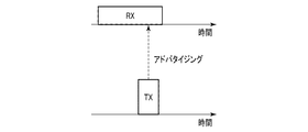
BLEにおいて採用されるパッシブスキャン方式では、図9に例示するように、新規ノードは自己の存在を周知するアドバタイズメントパケットを定期的に送信する。この新規ノードは、アドバタイズメントパケットを一度送信してから次に送信するまでの間に、低消費電力のスリープ状態に入ることで消費電力を節約できる。また、アドバタイズメントパケットの受信側も間欠的に動作するので、アドバタイズメントパケットの送受信に伴う消費電力は僅かである。
BLEにおいて採用されるパッシブスキャン方式では、図9に例示するように、新規ノードは自己の存在を周知するアドバタイズメントパケットを定期的に送信する。この新規ノードは、アドバタイズメントパケットを一度送信してから次に送信するまでの間に、低消費電力のスリープ状態に入ることで消費電力を節約できる。また、アドバタイズメントパケットの受信側も間欠的に動作するので、アドバタイズメントパケットの送受信に伴う消費電力は僅かである。
図10にBLE無線通信パケットの基本構造を示す。BLE無線通信パケットは、1バイトのプリアンブルと、4バイトのアクセスアドレスと、2~39バイト(可変)のプロトコルデータユニット(PDU:Protocol Data Unit)と、3バイトの巡回冗長チェックサム(CRC:Cyclic Redundancy Checksum)とを含む。BLE無線通信パケットの長さは、PDUの長さに依存し、10~47バイトである。10バイトのBLE無線通信パケット(PDUは2バイト)は、Empty PDUパケットとも呼ばれ、マスタとスレイブ間で定期的に交換される。
プリアンブルフィールドは、BLE無線通信の同期のために用意されており、「01」または「10」の繰り返しが格納される。アクセスアドレスは、アドバタイジングチャネルでは固定数値、データチャネルでは乱数のアクセスアドレスが格納される。本実施形態では、アドバタイジングチャネル上で伝送されるBLE無線通信パケットであるアドバタイズメントパケットを対象とする。CRCフィールドは、受信誤りの検出に用いられる。CRCの計算範囲は、PDUフィールドのみである。
次に、図11を用いて、アドバタイズメントパケットのPDUフィールドについて説明する。なお、データチャネル上で伝送されるBLE無線通信パケットであるデータ通信パケットのPDUフィールドは図11とは異なるデータ構造を有するが、本実施形態ではデータ通信パケットを対象としていないので説明を省略する。
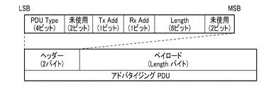
アドバタイズメントパケットのPDUフィールドは、2バイトのヘッダと、0~37バイト(可変)のペイロードとを含む。ヘッダは、さらに、4ビットのPDU Typeフィールドと、2ビットの未使用フィールドと、1ビットのTxAddフィールドと、1ビットのRxAddフィールドと、6ビットのLengthフィールドと、2ビットの未使用フィールドとを含む。
PDU Typeフィールドには、このPDUのタイプを示す値が格納される。「接続可能アドバタイジング」、「非接続アドバタイジング」などのいくつかの値が定義済みである。TxAddフィールドには、ペイロード中に送信アドレスがあるか否かを示すフラグが格納される。同様に、RxAddフィールドには、ペイロード中に受信アドレスがあるか否かを示すフラグが格納される。Lengthフィールドには、ペイロードのバイトサイズを示す値が格納される。
ペイロードには、任意のデータを格納することができる。そこで、データ送信装置100は、例えば図12に例示されるようなデータ構造を用いて、センサデータおよび日時データをペイロードに格納する。図12のデータ構造は、1人のユーザの血圧および脈拍の1回分のセンサデータを伝送するために使用可能である。なお、図12のデータ構造は、1人のユーザの血圧および脈拍の複数回分のセンサデータを伝送するように変形されてもよい。
User IDフィールドは、ユーザを特定する識別子が格納される。なお、ユーザの識別子の代わりに、或いは、これに加えて、データ送信装置100またはデータ受信装置200を特定する識別子が格納されてもよい。
latest flagは、後続するTimeフィールドに格納された日時データが日時の関連付けに使用可能であるか否かを表すフラグ(より一般化すれば、情報)である。このフラグがTRUEである場合には、Timeフィールドに格納された日時データの示すローカル日時を、時計部202の現在日時に関連付けることが許容される。
Timeフィールドは、日時データが格納される。Sys、DiaおよびPulseフィールドは、それぞれ、日時データに関連付けられる収縮期血圧(Systolic Blood Pressure)、拡張期血圧(Diastolic Blood Pressure)および脈拍数のデータが格納される。このように日時データに関連付けられるセンサデータは、1種に限られず複数種であってもよい。
データ受信装置200のソフトウェア構成の説明に戻ると、受信部201は、例えば、BLEのアドバタイズメントパケットからPDUのペイロードを抽出する。そして、受信部201は、図12のUser IDフィールドの値が不適切である(例えば、自己のユーザの値に一致しない)ならば受信パケットを破棄してもよい。他方、受信部201は、図12のUser IDフィールドの値が適切である(自己のユーザの値に一致する)ならば、latest flagに格納されたフラグと、Timeフィールドに格納された日時データと、Sys,DiaおよびPulseフィールドに格納されたセンサデータとを日時算出部203へ送る。
時計部202は、日時を指示する。時計部202は、例えば、固定周波数で振動する水晶発振器と、その出力を分周して1Hzの信号を得る分周回路と、この信号をカウントして日時を示すシリアル値を得るカウンタとを含む。時計部202(の保持するシリアル値)は、例えば、データ受信装置200が接続する基地局からのデータに基づいて自動補正されてもよい。
日時算出部203は、受信部201から、フラグと、日時データと、センサデータとを受け取る。日時算出部203は、フラグが日時データが日時の関連付けに使用可能であることを表すならば、時計部202の指示する現在日時を基準日時として、日時データの示すローカル日時と関連付ける(図13参照)。
なお、かかる関連付けが過去に実施済みである場合には、以後の実施は省略されてもよい。ただし、時計部202とデータ送信装置100の内蔵時計とで時間の進み方が一致しない場合には、両者の差が累積して大きな誤差を生むおそれがある。かかる誤差の累積を防ぐ観点では、基準日時とデータ送信装置100のローカル日時との関連付けを適宜リセットすることが推奨される。
他方、フラグが日時データが日時の関連付けに使用可能でないことを表すならば、この日時データは時計部202の指示する現在日時に比べて古すぎるので、関連付けることはできない。
日時算出部203は、日時データの示すローカル日時と、基準日時に関連付けられるローカル日時との差を算出する。そして、日時算出部203は、基準日時にこの差を加算することで、日時データの示すローカル日時に関連付けられる時計部202の日時を算出する。日時算出部203は、算出した日時によって、日時データを書き換える(図14参照)。日時算出部203は、書き換え後の日時データと、センサデータとをデータ管理部204へ送る。
なお、基準日時とデータ送信装置100のローカル日時との関連付けが行われるまで、日時算出部203は日時の書き換えを行うことはできない。かかる関連付けを行うには、データ送信装置100から日時の関連付けに使用可能な(略最新の)日時データを送信してもらい、これをデータ受信装置200が受信する必要がある。そこで、データ送信装置100に日時の関連付けに使用可能な日時データを送信させるためのトリガをいくつか用意される。
例えば、データ送信装置100は、ユーザの生体情報に関する量の測定を行って新たなセンサデータが発生した直後に当該センサデータの測定日時に相当する略最新の日時データをBLEのアドバタイズメントパケットに格納して送信してもよい。また、ユーザが与えた特定のユーザ入力をトリガとして、データ送信装置100は略最新の日時データをBLEのアドバタイズメントパケットに格納して送信してもよい。さらに、バッテリ交換をトリガとして、データ送信装置100は略最新の日時データをBLEのアドバタイズメントパケットに格納して送信してもよい。さらに、データ送信装置100は、所定の周期(例えば1日毎、1週間毎など)で、略最新の日時データをBLEのアドバタイズメントパケットに格納して送信してもよい。
また、基準日時とデータ送信装置100のローカル日時との関連付けが一度も行われていない場合、関連付けが最後に行われてからの経過時間が閾値を超えている場合などに、上記トリガの1つであるユーザ入力を促すテキスト、画像または音声をデータ受信装置200に出力させてもよい。
データ管理部204は、日時算出部203から日時データとセンサデータとを受け取り、これらを関連付けてデータ記憶部205に書き込む。また、データ管理部204は、例えば図示されない上位アプリケーション(例えば生体データの管理アプリケーション)からの命令に従って、データ記憶部205に格納されている日時データおよびセンサデータのセットを読み出し、送信部206または図示されない表示部へ送る。
データ記憶部205は、データ管理部204によって日時データおよびセンサデータのセットを読み書きされる。
送信部206は、データ管理部204から日時データおよびセンサデータのセットを受け取り、これらをネットワーク経由でサーバ300へ送信する(図3参照)。送信部206は、例えば移動通信またはWLANを利用する。なお、図3の例では、データ送信装置100として腕時計型のウェアラブル血圧計の外観が示されているが、データ送信装置100の外観はこれに限られず据え置き型の血圧計であってもよいし、他の生体情報または活動情報に関する量を測定するセンサ装置であり得る。
サーバ300は、多数のユーザのセンサデータ(主に生体データ)を管理するデータベースに相当する。サーバ300は、ユーザ自身のほか、例えば、ユーザの健康指導、保険加入査定、健康増進プログラムの成績評価などに供するために、健康指導者、保険会社またはプログラム運営者のPCなどからのアクセスに応じて当該ユーザの生体データを送信してもよい。
<データ送信装置>
次に、図6を用いて、本実施形態に係るデータ送信装置100のソフトウェア構成の一例を説明する。図6は、データ送信装置100のソフトウェア構成の一例を模式的に示す。
次に、図6を用いて、本実施形態に係るデータ送信装置100のソフトウェア構成の一例を説明する。図6は、データ送信装置100のソフトウェア構成の一例を模式的に示す。
図7に示した制御部111は、記憶部112に格納されているプログラムをRAMに展開する。そして、制御部111は、このプログラムをCPUにより解釈および実行して、図7に示した各種のハードウェア要素を制御する。これにより、図6に示されるとおり、データ送信装置100は、生体センサ101と、動きセンサ102と、時計部103と、入力部104と、データ管理部105と、データ記憶部106と、送信制御部107と、送信部108と、表示制御部109と、表示部110とを備えるコンピュータとして機能する。
生体センサ101は、ユーザの生体情報に関する量を測定することで生体データを得る。生体センサ101の動作は、例えば図示されないセンサ制御部によって制御される。生体センサ101は、生体データを時計部103から受け取った日時データに関連付けて、データ管理部105へ送る。生体センサ101は、典型的には、ユーザの血圧を測定することで血圧データを得る血圧センサを含む。この場合に、生体データは血圧データを含む。血圧データは、例えば、収縮期血圧および拡張期血圧の値と脈拍数とを含み得るが、これに限られない。このほか、生体データは、心電データ、脈波データ、体温データなどを含むことができる。
血圧センサは、ユーザの血圧を1拍毎に連続測定可能な血圧センサ(以降、連続型の血圧センサと称する)を含むことができる。連続型の血圧センサは、脈波伝播時間(PTT;Pulse Transit Time)からユーザの血圧を連続測定してもよいし、トノメトリ法または他の技法により連続測定を実現してもよい。
血圧センサは、連続型の血圧センサに代えて、または、加えて、連続測定不可能な血圧センサ(以降、非連続型の血圧センサと称する)を含むこともできる。非連続型の血圧センサは、例えば、カフを圧力センサとして用いてユーザの血圧を測定する(オシロメトリック法)。
非連続型の血圧センサ(特に、オシロメトリック方式の血圧センサ)は、連続型の血圧センサに比べて、測定精度が高い傾向にある。故に、血圧センサは、例えば、何らかの条件が満足する(例えば、連続型の血圧センサによって測定されたユーザの血圧データが所定の状態を示唆した)ことをトリガとして、連続型の血圧センサに代えて非連続型の血圧センサを作動させることにより、血圧データをより高い精度で測定してもよい。
動きセンサ102は、例えば、加速度センサまたはジャイロセンサであり得る。動きセンサ102は、当該動きセンサ102の受ける加速度/角速度を検出することで3軸の加速度/角速度データを得る。動きセンサ102の動作は、例えば図示されないセンサ制御部によって制御される。この加速度/角速度データは、データ送信装置100を装着しているユーザの活動状態(姿勢および/または動作)を推定するために用いることができる。動きセンサ102は、加速度/角速度データを時計部103から受け取った日時データに関連付けて、データ管理部105へ送る。
なお、生体センサ101および動きセンサ102のうち一方が省略されてもよい。また、生体センサ101および動きセンサ102に加えて、または、代えて、環境センサが設けられてもよい。環境センサは、例えば、温度センサ、湿度センサ、気圧センサなどを含み得る。すなわち、センサデータとは、センサが予め定められた物理量を測定し、測定結果に基づいて生成する任意のデータであり得る。
時計部103は、日時を指示する。時計部103は、例えば、固定周波数で振動する水晶発振器と、その出力を分周して1Hzの信号を得る分周回路と、この信号をカウントして日時を示すシリアル値を得るカウンタとを含む。時計部103は、現在日時を示す日時データ(例えば上記シリアル値)を生体センサ101および動きセンサ102へ送る。日時データは、生体センサ101による生体データの測定日時、動きセンサ102による加速度/角速度データの測定日時などとして用いることができる。このほか、日時データは、表示部110へ表示するために表示制御部109によって参照されたり、前述のTimeフィールドに格納された日時データが日時の関連付けに使用可能(略最新)であるか否かを表すフラグを設定するために、または、日時の関連付けに使用可能な(略最新の)日時データをアドバタイジングするために送信制御部107によって参照されたりする。
時計部103(の保持するシリアル値)は、例えば、ユーザ入力によって調整(時刻合わせ)可能に設計されてもよいが、前述のようにデータ受信装置200はデータ送信装置100のローカル日時の正誤に関わらず、日時データを適宜書き換えることができる。故に、敢えて、かかる設計としないことで、入力装置114を簡素化(ボタン数の削減等)してもよい。なお、この場合にも、例えば、「10分前」、「2時間前」、「昨日」、「1週間前」などの現在日時を基準とした相対的な日時をユーザに提示することは可能である。
入力部104は、ユーザ入力を受け付ける。ユーザ入力は、例えば、送信部108によるデータ送信を制御するためのものであったり、表示部110によるデータ表示を制御するためのものであったり、生体センサ101または動きセンサ102による測定を開始するためのものであったりする。
送信部108によるデータ送信を制御するためのユーザ入力は、例えば、特定の日時データおよびセンサデータのセットの送信を明示的または黙示的に指示するもの、日時の関連付けに使用可能な(略最新の)日時データの送信を明示的または黙示的に指示するものなどであり得る。
入力部104は、送信部108によるデータ送信を制御するためのユーザ入力を送信制御部107へ送り、表示部110によるデータ表示を制御するためのユーザ入力を表示制御部109へ送り、生体センサ101または動きセンサ102による測定を開始するためのユーザ入力を図示されないセンサ制御部へ送る。
データ管理部105は、生体センサ101または動きセンサ102から日時データに関連付けられたセンサデータ(生体データまたは加速度/角速度データ)を受け取り、これらをデータ記憶部106に書き込む。データ管理部105は、日時データおよびセンサデータを新たに受け取った場合に、これらを自動的に送信制御部107または表示制御部109へ送ってもよい。また、データ管理部105は、送信制御部107または表示制御部109からの命令をトリガとして、データ記憶部106に格納されている日時データおよびセンサデータのセットを読み出し、送信制御部107または表示制御部109へ送ってもよい。
データ記憶部106は、データ管理部105によって日時データおよびセンサデータのセットを読み書きされる。
送信制御部107は、データ管理部105から日時データおよびセンサデータのセットを受け取り、これらに基づいて、図10~図12を用いて説明したようなBLEのアドバタイズメントパケットを生成する。なお、送信制御部107は、前述のTimeフィールドに格納された日時データが日時の関連付けに使用可能であるか否かを表すフラグを設定するために、時計部103の保持する日時データを参照し、データ管理部105から受け取った日時データと比較してもよい。また、送信制御部107は、時計部103から日時の関連付けに使用可能な(略最新の)日時データを受け取り、これに基づいて、データ受信装置200へ日時の関連付けに使用可能な日時データをアドバタイジングするためのアドバタイズメントパケットを生成することもあり得る。送信制御部107は、生成したアドバタイズメントパケットを送信部108へ送る。
送信制御部107は、入力部104から、送信部108によるデータ送信を制御するためのユーザ入力を受け取ることがある。この場合に、送信制御部107は、ユーザ入力に基づいてデータ管理部105に特定の日時データおよびセンサデータのセットを要求したり、時計部103に略最新(日時の関連付けに使用可能である)の日時データを要求したりする。その他、送信制御部107は、過去に送信したデータの再送や、日時の関連付けに使用可能な日時データのアドバタイジングなどのために、ユーザ入力に関わらず、アドバタイズメントパケットを生成し得る。
送信部108は、送信制御部107からBLEのアドバタイズメントパケットを受け取り、これを送信(アドバタイジング)する。
表示制御部109は、データ管理部105から日時データおよびセンサデータのセットを受け取り、これらに基づいて表示部110の表示データを生成する。また、表示制御部109は、時計部103を参照して、時計部103の保持する日時データを表示部110に表示させるための表示データを生成することもある。表示制御部109は、生成した表示データを表示部110へ送る。
表示制御部109は、入力部104から、表示部110によるデータ表示を制御するためのユーザ入力を受け取ることがある。この場合に、表示制御部109は、ユーザ入力に基づいてデータ管理部105に特定の日時データおよびセンサデータのセットを要求したり、時計部103に略最新の日時データを要求したりする。
表示部110は、表示制御部109から表示データを受け取り、これを表示する。
<その他>
データ送信装置100およびデータ受信装置200の各機能に関しては後述する動作例で詳細に説明する。なお、本実施形態では、データ送信装置100およびデータ受信装置200の各機能がいずれも汎用のCPUによって実現される例について説明している。しかしながら、以上の機能の一部又は全部が、1又は複数の専用のプロセッサにより実現されてもよい。また、データ送信装置100およびデータ受信装置200それぞれのソフトウェア構成に関して、実施形態に応じて、適宜、機能の省略、置換及び追加が行われてもよい。
データ送信装置100およびデータ受信装置200の各機能に関しては後述する動作例で詳細に説明する。なお、本実施形態では、データ送信装置100およびデータ受信装置200の各機能がいずれも汎用のCPUによって実現される例について説明している。しかしながら、以上の機能の一部又は全部が、1又は複数の専用のプロセッサにより実現されてもよい。また、データ送信装置100およびデータ受信装置200それぞれのソフトウェア構成に関して、実施形態に応じて、適宜、機能の省略、置換及び追加が行われてもよい。
§3 動作例
<データ受信装置>
次に、図5を用いて、データ受信装置200の動作例を説明する。図5は、データ受信装置200の動作の一例を例示するフローチャートである。なお、以下で説明する処理手順は一例に過ぎず、各処理は可能な限り変更されてよい。また、以下で説明する処理手順について、実施の形態に応じて、適宜、ステップの省略、置換、及び追加が可能である。
<データ受信装置>
次に、図5を用いて、データ受信装置200の動作例を説明する。図5は、データ受信装置200の動作の一例を例示するフローチャートである。なお、以下で説明する処理手順は一例に過ぎず、各処理は可能な限り変更されてよい。また、以下で説明する処理手順について、実施の形態に応じて、適宜、ステップの省略、置換、及び追加が可能である。
図5の動作例は、データ受信装置200の受信部201が、データ送信装置100からBLEのアドバタイズメントパケット(日時データおよびセンサデータと、当該日時データが日時の関連付けに使用可能であるか否かを表すフラグとを格納したもの)を受信することで開始する。
まず、日時算出部203は、受信部201の受信したフラグを参照し、アドバタイズメントパケットに格納された日時データが日時の関連付けに使用可能であるか否かを判定する(ステップS401)。アドバタイズメントパケットが日時の関連付けに使用可能な日時データを含むならば処理はステップS402へと進み、そうでなければ処理はステップS403へと進む。
ステップS402において、日時算出部203は、基準日時とデータ送信装置100のローカル日時との関連付けをリセットする。すなわち、時計部202の指示する現在日時を基準日時として、受信した日時データの示すローカル日時と関連付ける。そして、処理はステップS404へと進む。
ステップS403において、日時算出部203は、日時の関連付けが実施済みであるか、すなわち、基準日時とデータ送信装置100のローカル日時との関連付けが過去になされているかを判定する。基準日時とデータ送信装置100のローカル日時との関連付けが過去になされていれば処理はステップS404へと進み、そうでなければ処理はステップS406へと進む。
ステップS404において、日時算出部203は、基準日時とデータ送信装置100のローカル日時との関連付けを利用して、受信した日時データの書き換えを行う。具体的には、日時算出部203は、受信した日時データの示すローカル日時と、基準日時に関連付けられるローカル日時との差を算出する。そして、日時算出部203は、基準日時にこの差を加算することで、日時データの示すローカル日時に関連付けられる時計部202の日時を算出する。日時算出部203は、算出した日時によって、日時データを書き換える。そして、処理はステップS405へと進む。
ステップS405において、データ管理部204は、ステップS404において書き換えられた日時データと、受信したセンサデータとを関連付けてデータ記憶部205に保存し、処理は終了する。
ステップS406において、日時算出部203は、基準日時とデータ送信装置100のローカル日時との関連付けが利用できないので、受信した日時データの書き換えを行うことができない。故に、所定のエラー処理が行われ、処理は終了する。このエラー処理は、例えば、データ送信装置100に日時の関連付けに使用可能な日時データをアドバタイジングさせるためのトリガとなるユーザ入力を促すテキスト、画像または音声をデータ受信装置200の出力装置215に出力させることを含み得る。受信した日時データおよびセンサデータは、破棄されてもよいが、保存されてもよい。受信した日時データおよびセンサデータを保存しておけば、その後に行われるであろう基準日時とデータ送信装置100のローカル日時との関連付けを利用して日時データを書き換えることで、データの欠落を防ぐことができる。
<データ送信装置>
次に、図8を用いて、データ送信装置100の動作例を説明する。図8は、データ送信装置100の動作の一例を例示するフローチャートである。なお、以下で説明する処理手順は一例に過ぎず、各処理は可能な限り変更されてよい。また、以下で説明する処理手順について、実施の形態に応じて、適宜、ステップの省略、置換、及び追加が可能である。
次に、図8を用いて、データ送信装置100の動作例を説明する。図8は、データ送信装置100の動作の一例を例示するフローチャートである。なお、以下で説明する処理手順は一例に過ぎず、各処理は可能な限り変更されてよい。また、以下で説明する処理手順について、実施の形態に応じて、適宜、ステップの省略、置換、及び追加が可能である。
図8の動作例は、図示されないセンサ制御部が生体センサ101に測定を開始するための命令を与えることで開始する。なお、図8の動作例に限らず、データ送信装置100は、予め定められた様々なトリガに応じて、時計部103の略最新の(日時の関連付けに使用可能な)日時データをBLEのアドバタイズメントパケットに格納して送信することができる。略最新の日時データは、センサデータに関連付けられて送信されてもよいし、センサデータとは独立に送信されてもよい。
生体センサ101は、ユーザの生体情報に関する量を測定して生体データ(センサデータ)を生成する(ステップS501)。この生体データは、時計部103の日時データと関連付けて、データ管理部105へ送られる。データ管理部105は、日時データおよび生体データのセットをデータ記憶部106へ書き込むとともに、アドバタイジングのために送信制御部107へ送る。そして、処理はステップS502へと進む。
ステップS502において、送信制御部107は、アドバタイジング対象の日時データの示す日時と時計部103の現在日時とを比較し、所定時間が経過したか否かを判定する。所定時間が経過していれば処理はステップS504へと進み、そうでなければ処理はステップS503へと進む。
この所定時間が大きいほど、データ受信装置200における基準日時とデータ送信装置100のローカル日時との関連付けの精度は低くなる(すなわち許容誤差が大きくなる)が、関連付けの行われる頻度は高くなる。一例として、データ受信装置200がセンサデータの測定時間を分単位で管理するのであれば、所定時間は数秒から数十秒程度に設定され得る。
ステップS503において、送信制御部107は、アドバタイジング対象の日時データが日時の関連付けに使用可能であることを表すフラグと、当該日時データと、ステップS501において測定された生体データとを格納したアドバタイズメントパケットを生成し、送信部108がこれを送信する。そして、処理はステップS505へと進む。
他方、ステップS504において、送信制御部107は、アドバタイジング対象の日時データが日時の関連付けに使用可能でないことを表すフラグと、当該日時データと、ステップS501において測定された生体データとを格納したアドバタイズメントパケットを生成し、送信部108がこれを送信(アドバタイジング)する。そして、処理はステップS505へと進む。
ステップS505では、ステップS503またはステップS504で送信したアドバタイズメントパケットの再送タイミングを待ち受ける。アドバタイズメントパケットの伝送のような片方向通信では、送信元は送信データが宛先によって正しく受信されたかどうかを確認することができないので、宛先におけるデータの欠落を想定してデータの再送を行うことが好ましい。再送タイミングが到来すると、処理はステップS502に戻る。
ステップS502からステップS505のループによれば、生体情報に関する量の測定(ステップS501)から所定時間が経過するまでは、アドバタイジング対象の日時データが日時の関連付けに使用可能であることを表すフラグを含んだアドバタイズメントパケットが繰り返し送信される。すなわち、データ受信装置200は、この所定時間が経過するまでにアドバタイズメントパケットを受信すれば、基準日時とデータ送信装置100のローカル日時との関連付けを行うことができる。
[作用・効果]
以上説明したように、本実施形態では、データ送信装置は、予め定められたトリガに応じて、時計部の略最新の(日時の関連付けに使用可能な)日時を示す日時データを含む片方向通信用のパケットを送信する。そして、データ受信装置は、このデータ送信装置から送信された日時データの示す日時を自己に内蔵された時計部の現在日時(基準日時)に関連付ける。以降、データ受信装置は、データ送信装置から送信されるセンサデータに関連付けられた日時データの示すデータ送信装置のローカル日時を自己に内蔵された時計部の指示する日時を基準に書き換える。従って、本実施形態によれば、データ送信装置に内蔵された時計部の時刻合わせが行われていない場合や、当該時計部が不正確な日時を指示する場合にも、データ受信装置はセンサデータに関連付けられる適切な日時を算出することができる。
以上説明したように、本実施形態では、データ送信装置は、予め定められたトリガに応じて、時計部の略最新の(日時の関連付けに使用可能な)日時を示す日時データを含む片方向通信用のパケットを送信する。そして、データ受信装置は、このデータ送信装置から送信された日時データの示す日時を自己に内蔵された時計部の現在日時(基準日時)に関連付ける。以降、データ受信装置は、データ送信装置から送信されるセンサデータに関連付けられた日時データの示すデータ送信装置のローカル日時を自己に内蔵された時計部の指示する日時を基準に書き換える。従って、本実施形態によれば、データ送信装置に内蔵された時計部の時刻合わせが行われていない場合や、当該時計部が不正確な日時を指示する場合にも、データ受信装置はセンサデータに関連付けられる適切な日時を算出することができる。
§4 変形例
以上、本発明の実施の形態を詳細に説明してきたが、前述までの説明はあらゆる点において本発明の例示に過ぎない。本発明の範囲を逸脱することなく種々の改良や変形を行うことができることは言うまでもない。例えば、以下のような変更が可能である。なお、以下では、上記実施形態と同様の構成要素に関しては同様の符号を用い、上記実施形態と同様の点については、適宜説明を省略した。以下の変形例は適宜組み合わせ可能である。
以上、本発明の実施の形態を詳細に説明してきたが、前述までの説明はあらゆる点において本発明の例示に過ぎない。本発明の範囲を逸脱することなく種々の改良や変形を行うことができることは言うまでもない。例えば、以下のような変更が可能である。なお、以下では、上記実施形態と同様の構成要素に関しては同様の符号を用い、上記実施形態と同様の点については、適宜説明を省略した。以下の変形例は適宜組み合わせ可能である。
<4.1>
例えば、上記実施形態では、データ送信装置は、センサデータと当該センサデータの測定日時を示す日時データとをBLEのアドバタイズメントパケットに格納して送信している。しかしながら、データ送信装置は、センサデータの測定日時を示す日時データに代えて、当該測定日時からの経過日時を示す日時差データをBLEのアドバタイズメントパケットに格納して送信してもよい。日時差データは、例えば、センサデータに関連付けられた日時データの示す(測定)日時と、時計部103の略最新の(すなわち、パケット送信時の)日時との差を算出することで導出可能である。
例えば、上記実施形態では、データ送信装置は、センサデータと当該センサデータの測定日時を示す日時データとをBLEのアドバタイズメントパケットに格納して送信している。しかしながら、データ送信装置は、センサデータの測定日時を示す日時データに代えて、当該測定日時からの経過日時を示す日時差データをBLEのアドバタイズメントパケットに格納して送信してもよい。日時差データは、例えば、センサデータに関連付けられた日時データの示す(測定)日時と、時計部103の略最新の(すなわち、パケット送信時の)日時との差を算出することで導出可能である。
この変形例では、データ受信装置は、時計部202の略最新の日時を用いて日時差データから日時データを算出する。具体的には、日時算出部203は、時計部202の略最新の日時から日時差データの示す差を差し引くことで、センサデータに関連付けられる日時を算出可能である。
この変形例によれば、データ送信装置100がセンサデータを送信する度に日時差データを算出する必要がある一方で、データ受信装置200は基準日時とデータ送信装置100のローカル日時との関連付けを行わなくても、センサデータに関連付けられる日時を算出することができる。
ただし、ここまで説明した実施形態は全て、あらゆる点において本発明の例示に過ぎない。本発明の範囲を逸脱することなく種々の改良や変形を行うことができることは言うまでもない。つまり、本発明の実施にあたって、実施形態に応じた具体的構成が適宜採用されてもよい。なお、各実施形態において登場するデータを自然言語により説明しているが、より具体的には、コンピュータが認識可能な疑似言語、コマンド、パラメータ、マシン語等で指定される。
§5 付記
上記各実施形態の一部または全部は、特許請求の範囲のほか以下の付記に示すように記載することも可能であるが、これに限られない。
(付記1)
データ送信装置と通信するデータ受信装置であって、
メモリと、
前記メモリに接続されたプロセッサと
を具備し、
前記プロセッサは、
(a)日時を指示する時計部と、
(b)前記データ送信装置から送信された片方向通信用のパケットを受信する受信部と、
(c)(1)前記パケットが、前記データ送信装置におけるローカル日時を示す第1の日時データと、前記第1の日時データが日時の関連付けに使用可能であることを表す情報とを含む場合に、前記第1の日時データにより示されるローカル日時に関連付けて前記時計部の指示する日時を基準日時としてメモリに保存し、(2)前記パケットが、センサデータと、当該センサデータに関連付けられる、前記データ送信装置におけるローカル日時を示す第2の日時データとを含む場合に、前記基準日時に関連付けられて前記メモリに保持されているローカル日時と前記第2の日時データの示すローカル日時との差と、前記メモリに保持されている前記基準日時とに基づいて第3の日時データを算出する算出部
として機能するように構成される、
データ受信装置。
(付記2)
メモリと、
前記メモリに接続されたプロセッサと
を具備し、
前記プロセッサは、
(a)日時を指示する時計部と、
(b)(1)前記時計部の日時を示す第1の日時データと、前記第1の日時データが日時の関連付けに使用可能であることを表す情報とを含む、片方向通信用の第1のパケット、および(2)センサによって測定されたセンサデータと当該センサデータの測定された時の前記時計部の日時を示す第2の日時データとを含む、片方向通信用の第2のパケットを送信する送信部
として機能するように構成される、
データ送信装置。
メモリと、
前記メモリに接続されたプロセッサと
を具備し、
前記プロセッサは、
(a)日時を指示する時計部と、
(b)(1)前記時計部の日時を示す第1の日時データと、前記第1の日時データが日時の関連付けに使用可能であることを表す情報とを含む、片方向通信用の第1のパケット、および(2)センサによって測定されたセンサデータと当該センサデータの測定された時の前記時計部の日時を示す第2の日時データとを含む、片方向通信用の第2のパケットを送信する送信部
として機能するように構成される、
データ送信装置。
(付記3)
データ送信装置と通信するデータ受信装置であって、
メモリと、
前記メモリに接続されたプロセッサと
を具備し、
前記プロセッサは、
(a)日時を指示する時計部と、
(b)前記データ送信装置から送信された片方向通信用のパケットを受信する受信部と、
(c)前記パケットが、センサデータと、当該センサデータに関連付けられる日時差データとを含む場合に、前記時計部の日時を用いて前記日時差データから前記センサデータの測定日時を表す日時データを算出する算出部
として機能するように構成され、
前記日時差データは、前記日時差データの関連付けられたセンサデータを前記パケットの送信元が測定したローカル日時と当該パケットの送信元が当該パケットを送信したローカル日時との差を示す、
データ受信装置。
(付記4)
メモリと、
前記メモリに接続されたプロセッサと
を具備し、
前記プロセッサは、
(a)日時を指示する時計部と、
(b)片方向通信用のパケットを送信する送信部
として機能するように構成され、
前記パケットは、センサによって測定されたセンサデータと当該センサデータの測定された時の前記時計部の日時および前記パケットを送信する時の前記時計部の日時の差を示す日時差データとを含む、
データ送信装置。
メモリと、
前記メモリに接続されたプロセッサと
を具備し、
前記プロセッサは、
(a)日時を指示する時計部と、
(b)片方向通信用のパケットを送信する送信部
として機能するように構成され、
前記パケットは、センサによって測定されたセンサデータと当該センサデータの測定された時の前記時計部の日時および前記パケットを送信する時の前記時計部の日時の差を示す日時差データとを含む、
データ送信装置。
100・・・データ送信装置
101・・・生体センサ
102・・・動きセンサ
103・・・時計部
104・・・入力部
105,204・・・データ管理部
106,205・・・データ記憶部
107・・・送信制御部
108,206・・・送信部
109・・・表示制御部
110・・・表示部
111,211・・・制御部
112,212・・・記憶部
113,213・・・通信インタフェース
114,214・・・入力装置
115,215・・・出力装置
116,216・・・外部インタフェース
117・・・バッテリ
200・・・データ受信装置
201・・・受信部
202・・・時計部
203・・・日時算出部
300・・・サーバ
101・・・生体センサ
102・・・動きセンサ
103・・・時計部
104・・・入力部
105,204・・・データ管理部
106,205・・・データ記憶部
107・・・送信制御部
108,206・・・送信部
109・・・表示制御部
110・・・表示部
111,211・・・制御部
112,212・・・記憶部
113,213・・・通信インタフェース
114,214・・・入力装置
115,215・・・出力装置
116,216・・・外部インタフェース
117・・・バッテリ
200・・・データ受信装置
201・・・受信部
202・・・時計部
203・・・日時算出部
300・・・サーバ
Claims (12)
- データ送信装置と、
前記データ送信装置と通信するデータ受信装置と
を具備する、データ伝送システムであって、
前記データ送信装置は、
日時を指示する第1の時計部と、
(1)前記第1の時計部の日時を示す第1の日時データと、前記第1の日時データが日時の関連付けに使用可能であることを表す情報とを含む、片方向通信用の第1のパケット、および(2)センサによって測定されたセンサデータと当該センサデータの測定された時の前記第1の時計部の日時を示す第2の日時データとを含む、片方向通信用の第2のパケットを送信する送信部と
を具備し、
前記データ受信装置は、
日時を指示する第2の時計部と、
前記データ送信装置から送信された前記第1のパケットおよび前記第2のパケットを受信する受信部と、
(1)前記第1のパケットが受信された場合に、前記第1の日時データにより示される前記第1の時計部の日時に関連付けて前記第2の時計部の指示する日時を基準日時としてメモリに保存し、(2)前記第2のパケットが受信された場合に、前記基準日時に関連付けられて前記メモリに保持されている日時と前記第2の日時データの示す日時との差と、前記メモリに保持されている前記基準日時とに基づいて第3の日時データを算出する算出部と
を具備する、
データ伝送システム。 - データ送信装置と通信するデータ受信装置であって、
日時を指示する時計部と、
前記データ送信装置から送信された片方向通信用のパケットを受信する受信部と、
(1)前記パケットが、前記データ送信装置におけるローカル日時を示す第1の日時データと、前記第1の日時データが日時の関連付けに使用可能であることを表す情報とを含む場合に、前記第1の日時データにより示されるローカル日時に関連付けて前記時計部の指示する日時を基準日時としてメモリに保存し、(2)前記パケットが、センサデータと、当該センサデータに関連付けられる、前記データ送信装置におけるローカル日時を示す第2の日時データとを含む場合に、前記基準日時に関連付けられて前記メモリに保持されているローカル日時と前記第2の日時データの示すローカル日時との差と、前記メモリに保持されている前記基準日時とに基づいて第3の日時データを算出する算出部と
を具備する、
データ受信装置。 - 日時を指示する時計部と、
(1)前記時計部の日時を示す第1の日時データと、前記第1の日時データが日時の関連付けに使用可能であることを表す情報とを含む、片方向通信用の第1のパケット、および(2)センサによって測定されたセンサデータと当該センサデータの測定された時の前記時計部の日時を示す第2の日時データとを含む、片方向通信用の第2のパケットを送信する送信部と
を具備する、
データ送信装置。 - 前記送信部は、前記センサデータの測定日時から所定時間が経過する前には、当該センサデータと当該センサデータの測定された時の前記時計部の日時を示す前記第1の日時データと当該第1の日時データが日時の関連付けに使用可能であることを表す情報とを含む前記第1のパケットを送信し、前記センサデータの測定日時から前記所定時間が経過した後には、当該センサデータと当該センサデータの測定された時の前記時計部の日時を示す前記第2の日時データと当該第2の日時データが日時の関連付けに使用可能でないことを表す情報とを含む第2のパケットを送信する、請求項3に記載のデータ送信装置。
- ユーザの操作情報の入力を受け付ける入力部をさらに具備し、
前記送信部は、前記操作情報の一部をトリガとして、前記時計部の日時を示す前記第1の日時データを含む第1のパケットを送信する、
請求項3または請求項4に記載のデータ送信装置。 - 前記データ送信装置は、バッテリにより駆動され、
前記送信部は、前記バッテリの交換をトリガとして、前記時計部の日時を示す前記第1の日時データを含む前記第1のパケットを送信する、
請求項3乃至請求項5のいずれか1項に記載のデータ送信装置。 - 前記センサデータは、血圧データである、請求項3乃至請求項6のいずれか1項に記載のデータ送信装置。
- データ送信装置と、
前記データ送信装置と通信するデータ受信装置と
を具備する、データ伝送システムであって、
前記データ送信装置は、
日時を指示する第1の時計部と、
片方向通信用のパケットを送信する送信部と
を具備し、
前記パケットは、センサによって測定されたセンサデータと当該センサデータの測定された時の前記第1の時計部の日時および前記パケットを送信する時の前記第1の時計部の日時の差を示す日時差データとを含み、
前記データ受信装置は、
日時を指示する第2の時計部と、
前記データ送信装置から送信された前記パケットを受信する受信部と、
前記パケットが受信された場合に、前記第2の時計部の日時を用いて前記日時差データから前記センサデータの測定日時を表す日時データを算出する算出部と
を具備する、
データ伝送システム。 - データ送信装置と通信するデータ受信装置であって、
日時を指示する時計部と、
前記データ送信装置から送信された片方向通信用のパケットを受信する受信部と、
前記パケットが、センサデータと、当該センサデータに関連付けられる日時差データとを含む場合に、前記時計部の日時を用いて前記日時差データから前記センサデータの測定日時を表す日時データを算出する算出部と
を具備し、
前記日時差データは、前記日時差データの関連付けられたセンサデータを前記パケットの送信元が測定したローカル日時と当該パケットの送信元が当該パケットを送信したローカル日時との差を示す、
データ受信装置。 - 日時を指示する時計部と、
片方向通信用のパケットを送信する送信部と
を具備し、
前記パケットは、センサによって測定されたセンサデータと当該センサデータの測定された時の前記時計部の日時および前記パケットを送信する時の前記時計部の日時の差を示す日時差データとを含む、
データ送信装置。 - 前記センサデータは、血圧データである、
請求項10に記載のデータ送信装置。 - データ送信装置から送信される片方向通信用のパケットを受信し処理するデータ受信装置に用いられる、前記パケットのデータ構造であって、
前記パケットは、センサデータと、当該センサデータに関連付けられる前記データ送信装置におけるローカル日時を示す第1の日時データと、前記第1の日時データが日時の関連付けに使用可能であるか否かを表す情報とを含み、
前記データ受信装置が、
前記受信されたパケットに含まれる前記情報に基づいて、前記第1の日時データが前記日時の関連付けに使用可能であるか否かを判定し、
前記第1の日時データが前記日時の関連付けに使用可能であると判定された場合に、前記受信されたパケットに含まれる前記第1の日時データの示すローカル日時に関連付けて、前記データ受信装置が備える時計部の日時を基準日時に設定する
処理に用いられる、パケットのデータ構造。
Priority Applications (3)
| Application Number | Priority Date | Filing Date | Title |
|---|---|---|---|
| DE112018004089.5T DE112018004089T5 (de) | 2017-08-09 | 2018-08-01 | Datenempfangsvorrichtung, Datenübertragungsvorrichtung und Datenübertragungssystem |
| CN201880048283.3A CN110945574B (zh) | 2017-08-09 | 2018-08-01 | 数据接收装置、发送装置、传送系统和包的数据结构 |
| US16/747,628 US11271667B2 (en) | 2017-08-09 | 2020-01-21 | Data receiving apparatus, data transmission apparatus and data transmission system |
Applications Claiming Priority (2)
| Application Number | Priority Date | Filing Date | Title |
|---|---|---|---|
| JP2017154762A JP7086541B2 (ja) | 2017-08-09 | 2017-08-09 | データ受信装置、データ送信装置およびデータ伝送システム |
| JP2017-154762 | 2017-08-09 |
Related Child Applications (1)
| Application Number | Title | Priority Date | Filing Date |
|---|---|---|---|
| US16/747,628 Continuation US11271667B2 (en) | 2017-08-09 | 2020-01-21 | Data receiving apparatus, data transmission apparatus and data transmission system |
Publications (1)
| Publication Number | Publication Date |
|---|---|
| WO2019031341A1 true WO2019031341A1 (ja) | 2019-02-14 |
Family
ID=65271039
Family Applications (1)
| Application Number | Title | Priority Date | Filing Date |
|---|---|---|---|
| PCT/JP2018/028824 WO2019031341A1 (ja) | 2017-08-09 | 2018-08-01 | データ受信装置、データ送信装置およびデータ伝送システム |
Country Status (5)
| Country | Link |
|---|---|
| US (1) | US11271667B2 (ja) |
| JP (1) | JP7086541B2 (ja) |
| CN (1) | CN110945574B (ja) |
| DE (1) | DE112018004089T5 (ja) |
| WO (1) | WO2019031341A1 (ja) |
Families Citing this family (1)
| Publication number | Priority date | Publication date | Assignee | Title |
|---|---|---|---|---|
| JP7251263B2 (ja) * | 2019-03-28 | 2023-04-04 | オムロンヘルスケア株式会社 | 測定機器 |
Citations (4)
| Publication number | Priority date | Publication date | Assignee | Title |
|---|---|---|---|---|
| JPH09305888A (ja) * | 1996-05-16 | 1997-11-28 | Casio Comput Co Ltd | 電子機器および当該電子機器を用いたシステム |
| JP2008183082A (ja) * | 2007-01-29 | 2008-08-14 | Seiko Epson Corp | 生体情報管理システム、中継装置、生体情報計測装置、中継装置の制御方法、生体情報計測装置の制御方法、中継装置の制御プログラム、及び、生体情報計測装置の制御プログラム |
| JP2008188379A (ja) * | 2007-02-08 | 2008-08-21 | Matsushita Electric Ind Co Ltd | 生体信号測定時刻修正システム |
| JP2008253480A (ja) * | 2007-04-04 | 2008-10-23 | Tanita Corp | 中継装置、中継方法、健康管理システム及びデータ管理システム |
Family Cites Families (17)
| Publication number | Priority date | Publication date | Assignee | Title |
|---|---|---|---|---|
| JPS5852620B2 (ja) | 1979-04-12 | 1983-11-24 | フロイント産業株式会社 | 代用粉乳 |
| JP3800229B2 (ja) * | 2004-09-08 | 2006-07-26 | オムロン株式会社 | 検知装置、異常監視システム、検知装置の制御プログラム、検知装置の制御プログラムを記録した記録媒体 |
| CN100342410C (zh) * | 2005-06-06 | 2007-10-10 | 重庆大学 | 无线生理信息传感器网络的时间同步方法与装置 |
| JP5169644B2 (ja) * | 2008-09-02 | 2013-03-27 | オムロンヘルスケア株式会社 | 血圧測定装置 |
| WO2010098379A1 (ja) * | 2009-02-26 | 2010-09-02 | オムロンヘルスケア株式会社 | 生体情報管理システムおよび生体情報管理方法 |
| EP2498536B1 (en) | 2009-11-06 | 2017-01-11 | Intertrust Technologies Corporation | Communication apparatus and communication method |
| JP5569051B2 (ja) * | 2010-03-11 | 2014-08-13 | オムロンヘルスケア株式会社 | 生体情報測定装置、生体情報管理システムおよび生体情報管理方法 |
| JP5673187B2 (ja) * | 2011-02-16 | 2015-02-18 | オムロン株式会社 | 物体検知システム |
| US8738925B1 (en) | 2013-01-07 | 2014-05-27 | Fitbit, Inc. | Wireless portable biometric device syncing |
| JP6123442B2 (ja) * | 2013-04-09 | 2017-05-10 | オムロン株式会社 | センサ装置、計測システム、および計測方法 |
| CA2911882C (en) * | 2013-05-09 | 2017-08-22 | Allflex Usa, Inc. | Animal health monitoring system |
| JP5852620B2 (ja) | 2013-09-26 | 2016-02-03 | 有限会社Gh9 | 低消費電力近距離無線通信システム |
| US20150127284A1 (en) * | 2013-11-03 | 2015-05-07 | Microsoft Corporation | Sensor Data Time Alignment |
| CN106102565A (zh) * | 2014-05-23 | 2016-11-09 | 三星电子株式会社 | 具有模块化传感器平台的可调节可穿戴系统 |
| CN205179369U (zh) * | 2014-11-26 | 2016-04-20 | 三星电子株式会社 | 用于与智能设备配对的可穿戴设备 |
| US9734682B2 (en) * | 2015-03-02 | 2017-08-15 | Enovate Medical, Llc | Asset management using an asset tag device |
| WO2016165026A1 (en) * | 2015-04-15 | 2016-10-20 | BeWhere Inc. | Asset management and control apparatus |
-
2017
- 2017-08-09 JP JP2017154762A patent/JP7086541B2/ja active Active
-
2018
- 2018-08-01 CN CN201880048283.3A patent/CN110945574B/zh active Active
- 2018-08-01 DE DE112018004089.5T patent/DE112018004089T5/de active Pending
- 2018-08-01 WO PCT/JP2018/028824 patent/WO2019031341A1/ja active Application Filing
-
2020
- 2020-01-21 US US16/747,628 patent/US11271667B2/en active Active
Patent Citations (4)
| Publication number | Priority date | Publication date | Assignee | Title |
|---|---|---|---|---|
| JPH09305888A (ja) * | 1996-05-16 | 1997-11-28 | Casio Comput Co Ltd | 電子機器および当該電子機器を用いたシステム |
| JP2008183082A (ja) * | 2007-01-29 | 2008-08-14 | Seiko Epson Corp | 生体情報管理システム、中継装置、生体情報計測装置、中継装置の制御方法、生体情報計測装置の制御方法、中継装置の制御プログラム、及び、生体情報計測装置の制御プログラム |
| JP2008188379A (ja) * | 2007-02-08 | 2008-08-21 | Matsushita Electric Ind Co Ltd | 生体信号測定時刻修正システム |
| JP2008253480A (ja) * | 2007-04-04 | 2008-10-23 | Tanita Corp | 中継装置、中継方法、健康管理システム及びデータ管理システム |
Also Published As
| Publication number | Publication date |
|---|---|
| CN110945574B (zh) | 2021-07-20 |
| US20200153526A1 (en) | 2020-05-14 |
| US11271667B2 (en) | 2022-03-08 |
| JP7086541B2 (ja) | 2022-06-20 |
| CN110945574A (zh) | 2020-03-31 |
| JP2019032777A (ja) | 2019-02-28 |
| DE112018004089T5 (de) | 2020-04-23 |
Similar Documents
| Publication | Publication Date | Title |
|---|---|---|
| US11171932B2 (en) | Data transmitting apparatus, data receiving apparatus, method and program | |
| US20210243581A1 (en) | Wireless device and wireless system | |
| US20190166222A1 (en) | Communication system | |
| US10881296B2 (en) | Measuring device and transmission method | |
| US11271667B2 (en) | Data receiving apparatus, data transmission apparatus and data transmission system | |
| US20200106571A1 (en) | Data communication system and data communication apparatus | |
| US11122015B2 (en) | Data transmitting apparatus | |
| US11223974B2 (en) | Data transmission apparatus and data reception apparatus | |
| US11317290B2 (en) | Information processing apparatus, server, and data transmission system | |
| WO2019031338A1 (ja) | 情報処理システム、データ送信装置、データ受信装置、情報処理方法及びプログラム | |
| US20200107755A1 (en) | Measuring device and transmission method | |
| US10972200B2 (en) | Data receiving apparatus and data transmitting apparatus | |
| JP6891072B2 (ja) | 情報処理装置、受信方法、およびプログラム | |
| JP6736975B2 (ja) | 生体情報測定装置、通信システム及び通信方法 | |
| WO2019031343A1 (ja) | データ伝送システムとそのデータ送信装置及びデータ受信装置 |
Legal Events
| Date | Code | Title | Description |
|---|---|---|---|
| 121 | Ep: the epo has been informed by wipo that ep was designated in this application |
Ref document number: 18845241 Country of ref document: EP Kind code of ref document: A1 |
|
| 122 | Ep: pct application non-entry in european phase |
Ref document number: 18845241 Country of ref document: EP Kind code of ref document: A1 |