WO2019027002A1 - スーパーキャパシタ - Google Patents
スーパーキャパシタ Download PDFInfo
- Publication number
- WO2019027002A1 WO2019027002A1 PCT/JP2018/029042 JP2018029042W WO2019027002A1 WO 2019027002 A1 WO2019027002 A1 WO 2019027002A1 JP 2018029042 W JP2018029042 W JP 2018029042W WO 2019027002 A1 WO2019027002 A1 WO 2019027002A1
- Authority
- WO
- WIPO (PCT)
- Prior art keywords
- metal oxide
- oxide layer
- oxygen
- lattices
- cerium
- Prior art date
- Legal status (The legal status is an assumption and is not a legal conclusion. Google has not performed a legal analysis and makes no representation as to the accuracy of the status listed.)
- Ceased
Links
Images


Classifications
-
- H—ELECTRICITY
- H01—ELECTRIC ELEMENTS
- H01G—CAPACITORS; CAPACITORS, RECTIFIERS, DETECTORS, SWITCHING DEVICES, LIGHT-SENSITIVE OR TEMPERATURE-SENSITIVE DEVICES OF THE ELECTROLYTIC TYPE
- H01G11/00—Hybrid capacitors, i.e. capacitors having different positive and negative electrodes; Electric double-layer [EDL] capacitors; Processes for the manufacture thereof or of parts thereof
- H01G11/10—Multiple hybrid or EDL capacitors, e.g. arrays or modules
- H01G11/12—Stacked hybrid or EDL capacitors
-
- H—ELECTRICITY
- H01—ELECTRIC ELEMENTS
- H01G—CAPACITORS; CAPACITORS, RECTIFIERS, DETECTORS, SWITCHING DEVICES, LIGHT-SENSITIVE OR TEMPERATURE-SENSITIVE DEVICES OF THE ELECTROLYTIC TYPE
- H01G11/00—Hybrid capacitors, i.e. capacitors having different positive and negative electrodes; Electric double-layer [EDL] capacitors; Processes for the manufacture thereof or of parts thereof
-
- H—ELECTRICITY
- H01—ELECTRIC ELEMENTS
- H01G—CAPACITORS; CAPACITORS, RECTIFIERS, DETECTORS, SWITCHING DEVICES, LIGHT-SENSITIVE OR TEMPERATURE-SENSITIVE DEVICES OF THE ELECTROLYTIC TYPE
- H01G11/00—Hybrid capacitors, i.e. capacitors having different positive and negative electrodes; Electric double-layer [EDL] capacitors; Processes for the manufacture thereof or of parts thereof
- H01G11/22—Electrodes
- H01G11/30—Electrodes characterised by their material
- H01G11/46—Metal oxides
-
- H—ELECTRICITY
- H01—ELECTRIC ELEMENTS
- H01G—CAPACITORS; CAPACITORS, RECTIFIERS, DETECTORS, SWITCHING DEVICES, LIGHT-SENSITIVE OR TEMPERATURE-SENSITIVE DEVICES OF THE ELECTROLYTIC TYPE
- H01G11/00—Hybrid capacitors, i.e. capacitors having different positive and negative electrodes; Electric double-layer [EDL] capacitors; Processes for the manufacture thereof or of parts thereof
- H01G11/54—Electrolytes
- H01G11/56—Solid electrolytes, e.g. gels; Additives therein
-
- H—ELECTRICITY
- H01—ELECTRIC ELEMENTS
- H01M—PROCESSES OR MEANS, e.g. BATTERIES, FOR THE DIRECT CONVERSION OF CHEMICAL ENERGY INTO ELECTRICAL ENERGY
- H01M10/00—Secondary cells; Manufacture thereof
- H01M10/05—Accumulators with non-aqueous electrolyte
- H01M10/056—Accumulators with non-aqueous electrolyte characterised by the materials used as electrolytes, e.g. mixed inorganic/organic electrolytes
- H01M10/0561—Accumulators with non-aqueous electrolyte characterised by the materials used as electrolytes, e.g. mixed inorganic/organic electrolytes the electrolyte being constituted of inorganic materials only
- H01M10/0562—Solid materials
-
- H—ELECTRICITY
- H01—ELECTRIC ELEMENTS
- H01M—PROCESSES OR MEANS, e.g. BATTERIES, FOR THE DIRECT CONVERSION OF CHEMICAL ENERGY INTO ELECTRICAL ENERGY
- H01M10/00—Secondary cells; Manufacture thereof
- H01M10/05—Accumulators with non-aqueous electrolyte
- H01M10/058—Construction or manufacture
- H01M10/0585—Construction or manufacture of accumulators having only flat construction elements, i.e. flat positive electrodes, flat negative electrodes and flat separators
-
- H—ELECTRICITY
- H01—ELECTRIC ELEMENTS
- H01M—PROCESSES OR MEANS, e.g. BATTERIES, FOR THE DIRECT CONVERSION OF CHEMICAL ENERGY INTO ELECTRICAL ENERGY
- H01M4/00—Electrodes
- H01M4/02—Electrodes composed of, or comprising, active material
- H01M4/13—Electrodes for accumulators with non-aqueous electrolyte, e.g. for lithium-accumulators; Processes of manufacture thereof
-
- H—ELECTRICITY
- H01—ELECTRIC ELEMENTS
- H01M—PROCESSES OR MEANS, e.g. BATTERIES, FOR THE DIRECT CONVERSION OF CHEMICAL ENERGY INTO ELECTRICAL ENERGY
- H01M4/00—Electrodes
- H01M4/02—Electrodes composed of, or comprising, active material
- H01M4/36—Selection of substances as active materials, active masses, active liquids
- H01M4/48—Selection of substances as active materials, active masses, active liquids of inorganic oxides or hydroxides
-
- Y—GENERAL TAGGING OF NEW TECHNOLOGICAL DEVELOPMENTS; GENERAL TAGGING OF CROSS-SECTIONAL TECHNOLOGIES SPANNING OVER SEVERAL SECTIONS OF THE IPC; TECHNICAL SUBJECTS COVERED BY FORMER USPC CROSS-REFERENCE ART COLLECTIONS [XRACs] AND DIGESTS
- Y02—TECHNOLOGIES OR APPLICATIONS FOR MITIGATION OR ADAPTATION AGAINST CLIMATE CHANGE
- Y02E—REDUCTION OF GREENHOUSE GAS [GHG] EMISSIONS, RELATED TO ENERGY GENERATION, TRANSMISSION OR DISTRIBUTION
- Y02E60/00—Enabling technologies; Technologies with a potential or indirect contribution to GHG emissions mitigation
- Y02E60/10—Energy storage using batteries
-
- Y—GENERAL TAGGING OF NEW TECHNOLOGICAL DEVELOPMENTS; GENERAL TAGGING OF CROSS-SECTIONAL TECHNOLOGIES SPANNING OVER SEVERAL SECTIONS OF THE IPC; TECHNICAL SUBJECTS COVERED BY FORMER USPC CROSS-REFERENCE ART COLLECTIONS [XRACs] AND DIGESTS
- Y02—TECHNOLOGIES OR APPLICATIONS FOR MITIGATION OR ADAPTATION AGAINST CLIMATE CHANGE
- Y02E—REDUCTION OF GREENHOUSE GAS [GHG] EMISSIONS, RELATED TO ENERGY GENERATION, TRANSMISSION OR DISTRIBUTION
- Y02E60/00—Enabling technologies; Technologies with a potential or indirect contribution to GHG emissions mitigation
- Y02E60/13—Energy storage using capacitors
-
- Y—GENERAL TAGGING OF NEW TECHNOLOGICAL DEVELOPMENTS; GENERAL TAGGING OF CROSS-SECTIONAL TECHNOLOGIES SPANNING OVER SEVERAL SECTIONS OF THE IPC; TECHNICAL SUBJECTS COVERED BY FORMER USPC CROSS-REFERENCE ART COLLECTIONS [XRACs] AND DIGESTS
- Y02—TECHNOLOGIES OR APPLICATIONS FOR MITIGATION OR ADAPTATION AGAINST CLIMATE CHANGE
- Y02P—CLIMATE CHANGE MITIGATION TECHNOLOGIES IN THE PRODUCTION OR PROCESSING OF GOODS
- Y02P70/00—Climate change mitigation technologies in the production process for final industrial or consumer products
- Y02P70/50—Manufacturing or production processes characterised by the final manufactured product
Definitions
- Embodiments generally relate to supercapacitors.
- Patent Document 1 discloses a Li-ion secondary battery using a Li composite oxide as a positive electrode active material.
- the Li-ion secondary battery is utilized as a battery of an electric device because miniaturization is also possible.
- a Li ion secondary battery is a battery having a structure in which Li ions are taken in and out through an electrolytic solution. Therefore, it is a battery in which an electrolytic solution is essential.
- lead storage batteries and nickel hydrogen storage batteries are batteries that require an electrolyte. Leakage of electrolyte may cause fire or explosion. For this reason, the lithium ion secondary battery has a sealed structure so as not to cause liquid leakage.
- problems such as deterioration due to long-term use, usage of electric devices, and liquid leakage due to use environment.
- Patent Document 2 discloses an electrode material for a Li-ion battery or a super capacitor.
- Li-ion batteries store electrical energy by chemical reaction at electrodes.
- the capacitor is a structure in which ion molecules store charge. For this reason, it is considered that the capacitor can be made to have a long life because deterioration at the time of charge and discharge is lower than that of the Li-ion battery.
- Patent Document 2 an electrolytic solution is used even if it is a super capacitor. For this reason, there was a problem of liquid leakage.
- Patent Document 3 discloses a fuel battery cell using a solid electrolyte using cerium oxide (CeO 2 ).
- JP 2001-338649 A Japanese Patent Application Publication No. 2003-123737 Japanese Patent Application Publication No. 2007-48653
- Cerium oxide is suitable for an electrode material of a solid electrolyte battery because of its oxide ion conductive property.
- the embodiment according to the present invention is for solving such a problem, and is for providing a super capacitor which can achieve high capacity.
- the supercapacitor according to the embodiment has a three-layer structure of a metal oxide layer capable of storing oxygen ions between lattices, a metal oxide layer conducting oxygen, and a metal oxide layer serving as an oxygen supply source.
- the supercapacitor according to the embodiment can have a high capacity because it has a three-layer structure of a target metal oxide layer. In addition, since there is no need to use the electrolytic solution, there is no fear of liquid leakage.
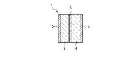
- FIG. 1 is a view showing an example of a super capacitor according to the embodiment.
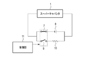
- FIG. 2 is a circuit diagram for measuring the performance of the super capacitor according to the embodiment.
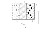
- FIG. 3 is a conceptual diagram showing an operation of charging the super capacitor of an example according to the embodiment.
- FIG. 4 is a conceptual diagram showing an operation of discharging an example super capacitor according to the embodiment.
- FIG. 5 is a view showing another example of the super capacitor according to the embodiment.
- the supercapacitor according to the embodiment has a three-layer structure of a metal oxide layer capable of storing oxygen ions between lattices, a metal oxide layer conducting oxygen, and a metal oxide layer serving as an oxygen supply source.
- a metal oxide layer capable of storing oxygen ions between lattices may be referred to as a first metal oxide layer.
- the metal oxide layer that conducts oxygen may be referred to as a second metal oxide layer.
- the metal oxide layer serving as an oxygen source may be referred to as a third metal oxide layer.
- a super capacitor utilizes the function of an electric double layer capacitor (Electric Double Layer Condenser; EDLC).
- EDLC Electro Mechanical Double Layer Condenser
- FIG. 1 shows an example of the supercapacitor according to the embodiment.
- 1 is a supercapacitor
- 2 is a metal oxide layer capable of storing oxygen ions between lattices
- 3 is a metal oxide layer conducting oxygen
- 4 is a metal oxide layer serving as an oxygen source
- 5 is an electrode
- 6 Is an electrode.
- the first metal oxide layer 2 capable of storing oxygen ions between lattices, the second metal oxide layer 3 conducting oxygen, and the third metal oxide layer 4 serving as an oxygen source are disposed in this order. It has a three-layer structure. One main surface of the first metal oxide layer 2 is in contact with one main surface of the second metal oxide layer 3. The other main surface of the second metal oxide layer 3 is in contact with one main surface of the third metal oxide layer 4.
- the electrodes 5 and 6 are provided outside the first metal oxide layer 2 and the third metal oxide layer 4 sandwiching the second metal oxide layer 3.
- the electrode 5 is in contact with the other main surface of the first metal oxide layer 2.
- the electrode 6 is in contact with the other main surface of the third metal oxide layer 4.
- the size in the planar direction of the electrodes 5 and 6 may be smaller than the size in the planar direction of the three-layer structure composed of each metal oxide layer.
- the plane direction as used herein refers to the in-plane direction of the plane orthogonal to the stacking direction in the three-layer structure.
- the metal oxide layer capable of storing oxygen ions between lattices is made of a metal oxide capable of storing oxygen ions between its crystal lattices.
- Such metal oxides are those whose valence is difficult to change.
- a metal oxide that can be included in the first metal oxide layer for example, it is selected from the group consisting of lanthanum oxide (La 2 O 3 ), hafnium oxide (HfO 2 ), and zirconium oxide (ZrO 2 ) One or more may be mentioned.
- La 2 O 3 is preferable as the lanthanum oxide.
- hafnium oxide HfO 2 are preferred.
- zirconium oxide is preferably ZrO 2 .
- These metal oxides are stable oxides in which a change in valence hardly occurs. Such metal oxides can store oxygen ions in the metal oxide layer.
- the metal oxide layer capable of storing oxygen ions between lattices preferably has a high film density. Also, the film density is preferably 95% or more. Further, in the metal oxide layer capable of storing oxygen ions between lattices, the thicker the film thickness is, the more the amount capable of storing oxygen ions increases. This can increase the capacitance of the capacitor. In addition, it is preferable that there is no oxygen deficiency.
- the film thickness of the first metal oxide layer capable of storing oxygen ions between lattices is preferably 1 ⁇ m or more, more preferably 30 ⁇ m or more.
- the metal oxide contained in the metal oxide layer which conducts oxygen is preferably at least one selected from the group consisting of cerium oxide (CeO 2 ) and yttrium-stabilized zirconia (YSZ).
- the oxygen conduction can move oxygen ions (O 2 ⁇ ) back and forth with the valence change of the metal oxide. Thereby, oxygen ions are moved to give the capacity as a capacitor.
- cerium oxide is valence-changed to Ce 4 + + + e ⁇ ⁇ Ce 3 + .
- Cerium oxide changes between trivalent and tetravalent due to the movement of oxygen ions. Therefore, when the oxygen-conductive second metal oxide layer contains cerium oxide, it is preferable that tetravalent cerium and trivalent cerium be present in the second metal oxide layer.
- the presence of tetravalent cerium (Ce 4 + ) and trivalent cerium (Ce 3 + ) enables active oxygen conduction.
- the presence of tetravalent cerium (Ce 4+ ) and trivalent cerium (Ce 3+ ) can be confirmed by X-ray diffraction (XRD) analysis. In the case of tetravalent cerium, a peak of CeO 2 is detected. In the case of trivalent cerium, a peak of Ce 2 O 3 is detected.
- cerium oxide is preferably CeO 2 .
- the crystal structure of cerium oxide (CeO 2 ) and yttrium-stabilized zirconia (YSZ) is a fluorite structure. Those having a fluorite structure exhibit oxygen conductivity.
- CeO 2 and YSZ may be doped with a rare earth element.
- the rare earth element to be doped is preferably a rare earth element other than cerium. Specifically, Y (yttrium), La (lanthanum), Gd (gadolinium), Yb (ytterbium), Nd (neodymium), Ho (holmium), Sm (samarium), Dy (dysprosium) may be mentioned.
- content of rare earth elements other than cerium 15 at% or less is preferable. If the content is 15 at% or less, the fluorite structure can be maintained. By containing a rare earth element other than cerium, the crystal structure is deficient and oxygen ions can easily move.
- One or more rare earth elements other than cerium can be contained. When two or more rare earth elements other than cerium are contained, the total content is preferably 15 at% or less. The content is preferably 1 at% or more and 15 at% or less. A more preferable content is 3 at% or more and 10 at% or less. If the content is less than 1 at%, the effect of addition is weak. If the content exceeds 15 at%, the fluorite structure may not be maintained.
- the oxygen-conductive second metal oxide layer have oxygen vacancies.
- Oxygen deficiency refers to the absence of some of the oxygen that makes up the crystal lattice.
- the crystal structure should be an amount capable of maintaining the fluorite structure.
- the subscript x in CeO 2-x is preferably in the range of 0 ⁇ x ⁇ 0.9.
- oxygen deficiency is preferably 15 at% or less, and more preferably 1 at% or more and 15 at% or less.
- the amount of oxygen deficiency can be measured by X-ray photoelectron spectroscopy (XPS).
- XPS X-ray photoelectron spectroscopy
- the x value in the above CeO 2-x can be determined by determining the peak area ratio between the trivalent cerium oxide peak and the tetravalent cerium oxide peak by XPS.
- Including rare earth elements other than cerium and providing oxygen deficiency may be combined. Care should be taken to maintain the fluorite structure even if both are used. By maintaining the fluorite structure as the crystal structure and adding a rare earth element or imparting oxygen deficiency, oxygen ions can easily move in the crystal. This improves the oxygen conductivity.
- the oxygen conducting metal oxide layer be thin. If the oxygen-conductive metal oxide layer is thick, it is difficult for oxygen ions to travel and the performance as a capacitor may be lost.
- the thickness of the oxygen-conductive metal oxide layer is preferably 10 ⁇ m or less.
- the film density of the metal oxide layer conducting oxygen be high.
- the metal oxide layer that conducts oxygen preferably has a larger crystal grain size.
- grain size is small, grain boundaries in the oxide layer increase. Grain boundaries serve as resistors when oxygen ions move, and may inhibit oxygen conduction. Therefore, the average particle diameter is preferably 1 ⁇ m or more.
- the film density is preferably 95% or more.
- the movement of oxygen ions occurs in the crystal that the crystal grain size is larger.
- the crystal grain size is preferably the same in the thickness direction of the second metal oxide layer that conducts oxygen. In this case, grain boundaries in the oxide layer can be reduced.
- the average particle diameter is preferably 1 ⁇ m.
- the average particle size can be determined from an SEM photograph of a cross section of the second metal oxide layer in the thickness direction taken by a scanning electron microscope (SEM).
- SEM scanning electron microscope
- the longest diagonal of the grain size of the crystallite shown in the SEM photograph is taken as the major axis, and the diagonal extending vertically from the center of the major axis is taken as the minor axis.
- the crystal grain size of 10 crystallites is determined based on the following formula (1), and the average value is taken as the average grain size.
- the film density can be measured by the Rutherford Backscattering Spectroscopy (RBS) method.
- the density obtained by the RBS method is taken as the actual measurement value. Also, the true density is used as the theoretical density.
- the film density is determined by the following equation (2).
- Pelletron 3SDH manufactured by National Electrostatics Corporation can be used as an apparatus for performing measurement by the RBS method.
- the measurement conditions are as follows: Incident ion: 4 He ++ Incident energy: 2300 keV Incident angle: 0 deg Scattering angle: 160 deg Sample current: 25 nA Beam diameter: 2 mm ⁇ In-plane rotation: No irradiation: 80 ⁇ C.
- the metal oxide layer which becomes an oxygen supply source contains the metal oxide which is a valence swing system.
- the valence fluctuation is the change of valence to form a stable oxide.
- the capacitor shows the performance of changing the valence by flowing electricity.
- a metal oxide at least one selected from the group consisting of praseodymium oxide and terbium oxide is preferable.
- Praseodymium oxide is stable in PrO 2 , Pr 2 O 3 , Pr 6 O 9 , Pr 6 O 11 .
- terbium oxide is stabilized by Tb 2 O 3 and Tb 4 O 7 .
- oxygen ions are eliminated and these are stabilized as oxides with different valences. Both can be stabilized with trivalent or tetravalent.
- the metal oxide layer serving as an oxygen source preferably has a high film density.
- the film density is preferably 95% or more.
- the thickness of the third metal oxide layer is preferably 1 ⁇ m or more, more preferably 30 ⁇ m or more.
- the oxygen partial pressure of the first metal oxide layer capable of storing oxygen ions between lattices is preferably in the range of ⁇ 7 eV or more and ⁇ 5 eV or less.
- the partial pressure of oxygen at which the valence of the second metal oxide layer which conducts oxygen is changed be in the range of ⁇ 5 eV or more and ⁇ 3 eV or less.
- the partial pressure of oxygen at which the valence of the third metal oxide layer serving as an oxygen supply source changes is in the range of -3 eV or more and -1 eV or less.
- oxygen partial pressure for each metal oxide layer is: oxygen partial pressure of first metal oxide layer ⁇ oxygen partial pressure of second metal oxide layer valence changes ⁇ third metal oxide layer It is preferable to satisfy the relationship of the oxygen partial pressure in which the valence changes.
- FIG. 2 shows a circuit diagram of an example for measuring the performance of the super capacitor according to the embodiment.
- 1 is a super capacitor
- 7 is a first switch
- 8 is a power supply
- 9 is a second switch
- 10 is a resistor
- 11 is a controller.
- the power source 8 may be, for example, a commercial power source, a generator, or a battery.
- the resistor 10 is a load such as a device that measures current or voltage, or an electrical device.
- a circuit including the first switch 7 and a circuit including the second switch 9 are electrically connected in parallel.
- the control unit 11 switches the circuit by operating the first switch 7 and the second switch 9.
- the power supply 8 and the supercapacitor 1 located on the circuit including the first switch 7 are electrically connected.
- the supercapacitor 1 can be charged by the current supplied from the power supply 8.
- the resistor 10 and the supercapacitor 1 on the circuit including the second switch 9 are electrically connected. Current may be discharged from supercapacitor 1 and supplied to resistor 10. By using a measuring device as the resistor 10, the performance of the super capacitor 1 can be measured.
- the supercapacitor 1 has a three-layer structure of a metal oxide layer 2 capable of storing oxygen ions between lattices, a metal oxide layer 3 conducting oxygen, and a metal oxide layer 4 serving as an oxygen supply source.
- a metal oxide layer 2 capable of storing oxygen ions between lattices
- a metal oxide layer 3 conducting oxygen
- a metal oxide layer 4 serving as an oxygen supply source.
- Oxygen ions are conducted in the oxygen oxide in the metal oxide layer 3 which conducts oxygen, and oxygen ions are stored in the metal oxide layer 2 which can store oxygen ions between the lattices. As a result, the battery is charged.
- oxygen ions move from the metal oxide layer 2 capable of storing oxygen ions between lattices to the metal oxide layer 4 serving as an oxygen supply source.
- a charge / discharge function can be provided.
- a metal oxide layer 2 capable of storing oxygen ions between lattices via the metal oxide layer 3 which conducts oxygen ions (O 2 ⁇ ) generated in the metal oxide layer 4 serving as an oxygen supply source Can be stored in
- FIG. 3 illustrates the operation of charging an example super capacitor.
- 1 is a supercapacitor
- 2 is a first metal oxide layer capable of storing oxygen ions between lattices
- 3 is a second metal oxide layer conducting oxygen
- 4 is a third metal oxide layer serving as an oxygen supply source
- 5 is an electrode
- 6 is an electrode
- 8 is a power source
- 12 is an oxygen ion
- 13 is an oxygen deficiency.
- oxygen ions 12 and oxygen vacancies in the third metal oxide layer 4 13 will occur.
- the oxygen ions 12 drift to move to the oxygen conducting second metal oxide layer 3 and are induced to the first metal oxide layer 2 capable of storing oxygen ions between the lattices.
- oxygen ions 12 accumulate in the first metal oxide layer 2.
- electrons are accumulated in the electrode 6.
- oxygen vacancies 13 can be concentrated near the electrode 6.
- oxygen ions drift and move during charging, whereby charges are accumulated at both ends in the stacking direction of the metal oxide layers in the supercapacitor 1.
- FIG. 4 shows the operation of discharging an example super capacitor.
- 1 is a supercapacitor
- 2 is a first metal oxide layer capable of storing oxygen ions between lattices
- 3 is a second metal oxide layer conducting oxygen
- 4 is a third metal oxide layer serving as an oxygen supply source
- 5 is an electrode
- 6 is an electrode
- 10 is a resistance
- 12 is an oxygen ion
- 13 is an oxygen deficiency.
- the metal oxide layer capable of storing oxygen ions between lattices or the metal oxide layer serving as an oxygen source do not have oxygen vacancies.
- the oxygen deficiency reduces the effect of storing or generating oxygen ions (O 2 ⁇ ).
- the thickness of the oxygen conducting metal oxide layer 3 is preferably thinner than the thickness of the metal oxide layer 2 capable of storing oxygen ions between the lattices and the thickness of the metal oxide layer 4 serving as an oxygen supply source. . As described above, it is easier to conduct oxygen if the oxygen conducting metal oxide layer 3 is thinner. If the metal oxide layer 2 and the metal oxide layer 4 are thinner than the metal oxide layer 3, oxygen ions conducted in the metal oxide layer 3 can not be sufficiently stored in the metal oxide layer 2.
- the thickness of each metal oxide layer mentioned above refers to the thickness in the stacking direction of the metal oxide layer in the three-layer structure.
- the total thickness of each metal oxide layer (the thickness of the three-layer structure) is preferably determined by the voltage to which the supercapacitor is applied.
- the applied electric field is preferably 0.001 MV / cm or more and 10 MV / cm or less.
- the total thickness is preferably in the range of 1 ⁇ m to 10000 ⁇ m.
- the total thickness is the sum of the total thickness of the metal oxide layers and the thickness of the barrier layer to be described later.
- the electrodes 5 and 6 are formed of a material exhibiting conductivity.
- the electrodes 5 and 6 preferably contain tungsten as a main component.
- the electrode 5 is an electrode provided on a metal oxide layer capable of storing oxygen ions between lattices.
- the electrode 6 is an electrode provided on a metal oxide layer serving as an oxygen supply source.
- Tungsten as a main component means a material containing 50 wt% or less and 100 wt% or less of tungsten in an electrode. Tungsten has an effect of adsorbing unnecessary oxygen contained in the metal oxide. For this reason, it is possible to remove excess oxygen contained in the metal oxide before conducting electricity.
- Tungsten is a material that hardly reacts with the metal oxide layer 2 capable of storing oxygen ions between lattices and the metal oxide layer 4 serving as an oxygen supply source. Therefore, the performance of the metal oxide layer 2 and the metal oxide layer 4 is not degraded.
- the supercapacitor has a barrier layer on the surface of the first metal oxide layer capable of storing oxygen ions between lattices and on the surface of the third metal oxide layer serving as an oxygen source.
- FIG. 5 shows an example of a cell structure provided with a barrier layer.
- 1 is a supercapacitor
- 2 is a first metal oxide layer capable of storing oxygen ions between lattices
- 3 is a second metal oxide layer conducting oxygen
- 4 is a third metal oxide layer serving as an oxygen supply source
- 5 is an electrode
- 6 is an electrode
- 14 is a barrier layer.
- One of the two barrier layers 14 is one of the surfaces of the first metal oxide layer 2 capable of storing oxygen ions between the lattices and the surface of the first metal oxide layer 2 in contact with the second metal oxide layer 3 It is provided on the opposite surface. That is, the barrier layer 14 is provided between the first metal oxide layer 2 and the electrode 5.
- the other barrier layer 14 is a surface of the third metal oxide layer 4 serving as an oxygen supply source on the side opposite to the surface in contact with the second metal oxide layer 3 of the third metal oxide layer 4.
- the barrier layer 14 is provided between the third metal oxide layer 4 and the electrode 6.
- the size in the planar direction of the barrier layer 14 may be equal to or larger than the size in the planar direction of the electrode (the electrode 5 or the electrode 6) in contact with the barrier layer 14.
- the supercapacitor according to the embodiment performs charge and discharge by the movement of oxygen ions.
- the barrier layer having the covalent bonding property By providing the barrier layer having the covalent bonding property, the movement of oxygen ions can be suppressed in the three-layer structure. Thereby, the capacitance of the super capacitor can be further improved.
- the capacity By providing the barrier layer, the capacity can be increased by 10% or more.
- the barrier layer preferably contains a material that is covalent and has a large band gap.
- Such materials include silicon oxide (SiO 2 ), aluminum oxide (Al 2 O 3 ), and germanium oxide (Ge 2 O 3 ).
- silicon oxide (SiO 2 ) and aluminum oxide (Al 2 O 3 ) are inexpensive materials. Therefore, the barrier layer 14 is preferably made of silicon oxide (SiO 2 ) or aluminum oxide (Al 2 O 3 ).
- the thickness of the barrier layer is preferably 5 nm or more and 100 nm or less.
- the presence or absence of high capacity by the barrier layer can be measured by differential capacity using an LCR meter.
- LCR meter there is a method of applying a constant voltage and determining the capacitance when the steady state is reached.
- a steady state is established after one minute by the application of 4V. Therefore, it shall measure with an LCR meter one minute after 4V application.
- the letters L, C and R in the LCR meter name mean inductance (L), capacitance (C) and resistance (R), respectively.
- the super capacitor as described above can efficiently generate oxygen ions, conduct oxygen, and store oxygen ions. Therefore, high capacity can be achieved.
- each layer is formed of a metal oxide layer, no electrolytic solution is used. For this reason, there is no concern of liquid leakage.
- the manufacturing method of the supercapacitor according to the embodiment is not particularly limited as long as it has the above configuration, but the following may be mentioned as a method for obtaining with high yield.
- the electrode is preferably made of metal.
- the metal preferably contains tungsten as a main component. Further, in the case of a metal electrode, it can be formed by a film forming technique such as sputtering or plating.
- a metal oxide layer 2 capable of storing oxygen ions, a metal oxide layer 3 capable of conducting oxygen, and a metal oxide layer 4 serving as an oxygen supply source are sequentially stacked between lattices.
- Each oxide layer can be formed by sputtering, chemical vapor deposition (CVD), spin coating, electron beam evaporation, or powder coating.
- Sputtering, CVD, spin coating, and electron beam evaporation are methods of forming a metal oxide layer directly.
- Powder application is a method of applying and drying a target metal oxide as a paste.
- the metal oxide layer is to be heat-treated at 500 ° C. or higher, as necessary. The heat treatment can eliminate OH groups in the metal oxide layer. If the OH group is present, it reacts with oxygen ions to block oxygen conduction.
- the heat treatment also has the effect of growing grains of the metal oxide of the oxygen-conductive second metal oxide layer to increase the average grain size.
- the impurity content in each oxide layer is preferably 5 wt% or less.
- the other electrode is provided thereon.
- the order of forming the electrode, the first to third metal oxide layers, and the other electrode may be reversed to that described above. That is, after providing an electrode on a base material, a third metal oxide layer, a second metal oxide layer, and a first metal oxide layer are sequentially laminated to form a three-layer structure, and then an electrode is provided. May be
- a barrier layer is provided on the electrode before providing each metal oxide layer.
- a barrier layer is provided thereon. A film formation method similar to that of each metal oxide layer can be used to form the barrier layer.
- the oxygen-conductive second metal oxide layer can contain a rare earth element other than cerium.
- a method of incorporating a rare earth element other than cerium into the second metal oxide layer (1) a method of forming a second metal oxide layer and then implanting it (such as ion implantation), (2) sputtering, etc.
- a method of dispersing a rare earth element other than cerium in a film atmosphere, (3) using a metal oxide powder containing a rare earth element other than cerium as a raw material, and the like can be mentioned.
- oxygen deficiency can be provided in the second metal oxide layer.
- a method of providing an oxygen deficiency (I) a method of heat-treating the second metal oxide layer in a non-oxidizing atmosphere can be mentioned.
- a non-oxidizing atmosphere an inert atmosphere (such as nitrogen and argon) and a reducing atmosphere (such as hydrogen) can be mentioned.
- a method of using a metal oxide in which an oxygen vacancy is provided in advance as a raw material may be mentioned.
- Other methods include (III) a method of reducing the amount of oxygen in a film forming atmosphere such as sputtering. For example, when reactive sputtering is performed, a metal oxide layer having an oxygen vacancy can be formed by reducing the amount of oxygen in the sputtering atmosphere.
- a supercapacitor including a first metal oxide layer capable of storing oxygen ions between lattices, a second metal oxide layer conducting oxygen, and a third metal oxide layer serving as an oxygen supply source.
- the first metal oxide layer, the second metal oxide layer, and the third metal oxide layer form a three-layer structure.
- This supercapacitor can exhibit high capacitance. Also, with this super capacitor, there is no concern of liquid leakage.
- Example 1 (Example 1-9)
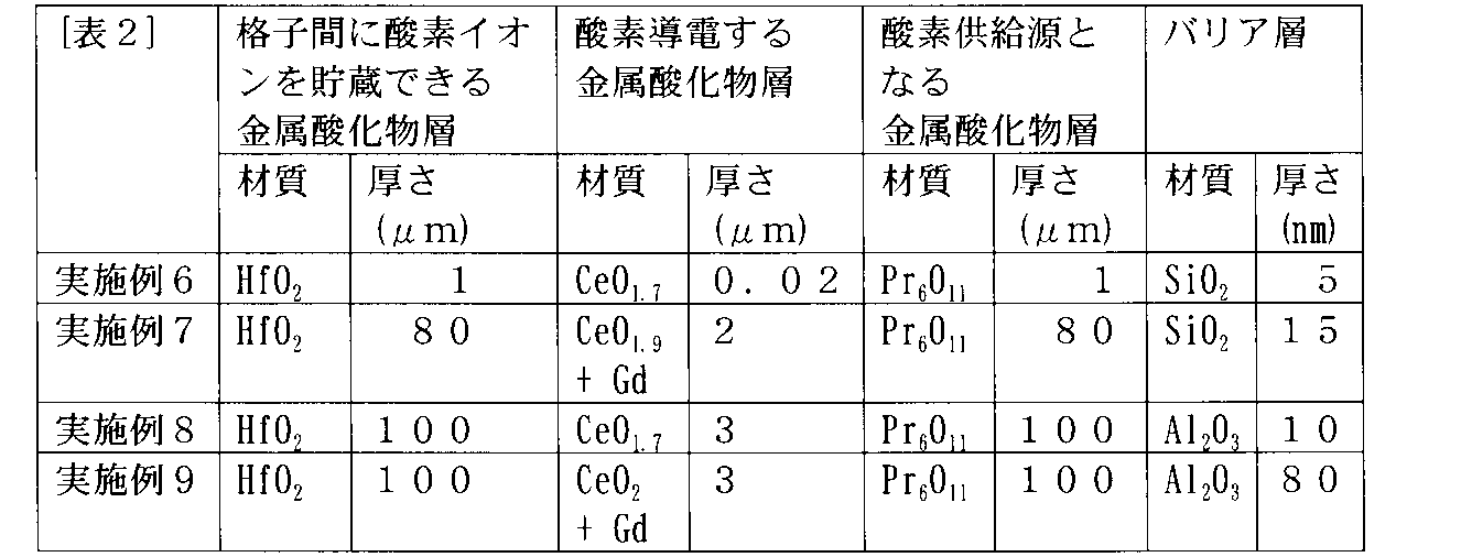
- the thing of Table 1 and Table 2 was prepared as a metal oxide layer which can store an oxygen ion between lattices, a metal oxide layer which carries out oxygen conduction, and a metal oxide layer used as an oxygen supply source.
- the electrode was a tungsten electrode (tungsten 100 wt%). Further, after forming each metal oxide layer, heat treatment at 500 ° C. or higher was performed. The film density of each metal oxide layer was 95% or more.
- the oxygen-conductive metal oxide layer according to Example 1-5 and Example 7-9 had an average particle diameter of 1 ⁇ m or more.
- Example 6 the metal oxide powder was applied in the form of a paste, and was applied and fired to form each metal oxide layer.
- a second metal oxide layer conducting oxygen was formed by electron beam evaporation.
- the first metal oxide layer and the third metal oxide layer were formed by applying and baking a metal oxide powder paste also in Example 6.
- Example 6-9 a barrier layer was provided between the three-layer structure of each metal oxide layer and the electrode.
- oxygen deficiency was provided in the second metal oxide layer.
- the cerium oxide is represented by CeO 2-x
- a second metal oxide layer was formed using a metal oxide powder in which Gd was contained in CeO 2 at a content of 7 at%, and an oxygen vacancy was further provided in the second metal oxide layer.
- cerium oxide is represented by CeO 2-x
- a second metal oxide layer was formed using a metal oxide powder in which Gd was contained in CeO 2 at a content of 7 at%. In Example 9, oxygen deficiency is not provided.
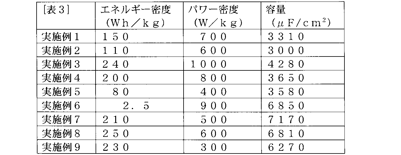
- a charge and discharge test was performed using a charge and discharge device in a voltage range from 0 V to a voltage corresponding to an electric field of 0.01 MV / cm. Charging was first performed in a constant current mode, and when reaching a voltage equivalent to an electric field of 0.01 MV / cm, transition was made to the constant voltage mode of the same charging voltage, and charging was continued until the amount of current decreased to a constant value. After completion of charging, discharge was performed at a constant current, and the energy density (electric capacity) of the supercapacitor was determined from the electric capacity at the time of discharge.
- the power density (W / kg) was determined by the formula of 0.25 ⁇ (V 2 -V 1 ) / R / cell weight.
- V 2 is the discharge starting voltage
- V 1 is the discharge end voltage
- R is the cell resistance (cell electrode area 200 cm 2).
- the cell weight in calculating the energy density and the power density includes a first metal oxide layer capable of storing oxygen ions between lattices, a second metal oxide layer conducting oxygen, and an oxygen supply source.
- the total weight with the three metal oxide layers that is, the weight of the three-layer structure of these metal oxide layers was taken as the cell weight.
- the capacity was also measured.
- the capacity was measured by an LCR meter, and the capacity after 1 minute was determined as a differential capacity at 4 V application.
- the supercapacitor according to the example has improved energy density and power density. It has been found that even the solid type that does not use an electrolytic solution exhibits excellent performance. Also, it was confirmed that the supercapacitors according to any of the examples were conducting oxygen.
- the capacitance was improved in the supercapacitors of the other examples using cerium oxide as compared with the supercapacitor of the second example using YSZ as the second metal oxide layer.
- XRD analysis was performed with respect to what used the cerium oxide for the oxygen-conductive 2nd metal oxide layer, tetravalent and trivalent cerium were confirmed. It is inferred that the capacity in the case of using cerium oxide is improved by the presence of tetravalent cerium and trivalent cerium.
- the performance is further improved by providing a barrier layer or providing a defect in the second metal oxide layer.
- a first metal oxide layer capable of storing oxygen ions between lattices, a second metal oxide layer conducting oxygen, and a third metal serving as an oxygen supply source A supercapacitor having a three-layer structure of oxide layers is provided. This supercapacitor can exhibit high capacitance. Also, with this super capacitor, there is no concern of liquid leakage.
- a supercapacitor having a three-layer structure of a metal oxide layer capable of storing oxygen ions between lattices, a metal oxide layer conducting oxygen, and a metal oxide layer serving as an oxygen supply source.
- the metal oxide layer capable of storing oxygen ions between lattices is one selected from lanthanum oxide (La 2 O 3 ), hafnium oxide (HfO 2 ), and zirconium oxide (ZrO 2 ) [1]
- the metal oxide layer conducting oxygen is at least one selected from cerium oxide (CeO 2 ) and yttrium-stabilized zirconia (YSZ) [1] or [2] Super capacitor as described in.
- An electrode provided on a metal oxide layer capable of storing oxygen ions between lattices or a metal oxide layer serving as an oxygen supply source contains tungsten as a main component, any one of [1] to [5]
- the metal oxide layer capable of storing oxygen ions between lattices or the metal oxide layer serving as an oxygen source has no oxygen deficiency, and any one of [1] to [6] Super capacitor as described in.
- the thickness of the oxygen conducting metal oxide layer is characterized by being thinner than the thickness of the metal oxide layer capable of storing oxygen ions between the lattices and the thickness of the metal oxide layer serving as an oxygen source.
- the super capacitor according to any one of [1] to [7].
Landscapes
- Engineering & Computer Science (AREA)
- Chemical & Material Sciences (AREA)
- Power Engineering (AREA)
- Electrochemistry (AREA)
- Chemical Kinetics & Catalysis (AREA)
- Microelectronics & Electronic Packaging (AREA)
- General Chemical & Material Sciences (AREA)
- Materials Engineering (AREA)
- Inorganic Chemistry (AREA)
- Manufacturing & Machinery (AREA)
- Physics & Mathematics (AREA)
- Condensed Matter Physics & Semiconductors (AREA)
- General Physics & Mathematics (AREA)
- Electric Double-Layer Capacitors Or The Like (AREA)
Abstract
Description
粒径 = (長径+短径)÷2 (1)
膜密度(%) = (実測値/理論密度)×100 (2)
入射イオン : 4He++
入射エネルギー : 2300 keV
入射角 : 0 deg
散乱角 : 160 deg
試料電流 : 25 nA
ビーム径 : 2 mm φ
面内回転 : 無
照射量 : 80 μC。
(実施例1-9)
格子間に酸素イオンを貯蔵できる金属酸化物層、酸素導電する金属酸化物層、酸素供給源となる金属酸化物層として、表1及び表2のものを用意した。また、電極はタングステン電極(タングステン100wt%)とした。また、各金属酸化物層を形成した後、500℃以上の熱処理を行った。また、各金属酸化物層の膜密度は95%以上のものとした。また、実施例1-5及び実施例7-9にかかる酸素導電する金属酸化物層は平均粒径1μm以上のものとした。

Claims (13)
- 格子間に酸素イオンを貯蔵できる金属酸化物層と、酸素導電する金属酸化物層と、酸素供給源となる金属酸化物層との3層構造を有する、スーパーキャパシタ。
- 前記格子間に酸素イオンを貯蔵できる金属酸化物層が含む金属酸化物は、酸化ランタン、酸化ハフニウム、酸化ジルコニウムからなる群より選ばれる1種以上である、請求項1記載のスーパーキャパシタ。
- 前記酸素導電する金属酸化物層が含む金属酸化物は、酸化セリウム、イットリウム安定化ジルコニアからなる群より選ばれる1種以上である、請求項1ないし請求項2のいずれか1項に記載のスーパーキャパシタ。
- 前記酸素供給源となる金属酸化物層が価数揺動系である金属酸化物を含む、請求項1ないし請求項3のいずれか1項に記載のスーパーキャパシタ。
- 前記酸素供給源となる金属酸化物層が含む金属酸化物は、酸化プラセオジム、酸化テルビウムからなる群より選ばれる1種以上である、請求項1ないし請求項4のいずれか1項に記載のスーパーキャパシタ。
- 前記格子間に酸素イオンを貯蔵できる金属酸化物層および前記酸素供給源となる金属酸化物層にそれぞれ設けられる電極をさらに具備し、前記電極がタングステンを主成分とする、請求項1ないし請求項5のいずれか1項に記載のスーパーキャパシタ。
- 前記格子間に酸素イオンを貯蔵できる金属酸化物層または前記酸素供給源となる金属酸化物層は酸素欠損を有していない、請求項1ないし請求項6のいずれか1項に記載のスーパーキャパシタ。
- 前記酸素導電する金属酸化物層の厚さは、前記格子間に酸素イオンを貯蔵できる金属酸化物層の厚さおよび前記酸素供給源となる金属酸化物層の厚さよりも薄い、請求項1ないし請求項7のいずれか1項に記載のスーパーキャパシタ。
- 前記酸素導電する金属酸化物層は酸化セリウムを含み、前記酸素導電する金属酸化物層には4価のセリウムと3価のセリウムとが存在する、請求項1ないし請求項8のいずれか1項に記載のスーパーキャパシタ。
- 前記酸素導電する金属酸化物層は酸素欠損を有している、請求項1ないし請求項9のいずれか1項に記載のスーパーキャパシタ。
- 前記酸素導電する金属酸化物層は、セリウム以外の希土類元素を含有している、請求項1ないし請求項10のいずれか1項に記載のスーパーキャパシタ。
- 前記格子間に酸素イオンを貯蔵できる金属酸化物層の表面および前記酸素供給源となる金属酸化物層の表面にバリア層をそれぞれ有する、請求項1ないし請求項11のいずれか1項に記載のスーパーキャパシタ。
- 前記バリア層が、酸化珪素または酸化アルミニウムを含む、請求項12記載のスーパーキャパシタ。
Priority Applications (3)
| Application Number | Priority Date | Filing Date | Title |
|---|---|---|---|
| KR1020197034732A KR102350812B1 (ko) | 2017-08-03 | 2018-08-02 | 슈퍼 커패시터 |
| CN201880036705.5A CN110720132B (zh) | 2017-08-03 | 2018-08-02 | 超级电容器 |
| JP2019534580A JP7150729B2 (ja) | 2017-08-03 | 2018-08-02 | スーパーキャパシタ |
Applications Claiming Priority (2)
| Application Number | Priority Date | Filing Date | Title |
|---|---|---|---|
| JP2017-151014 | 2017-08-03 | ||
| JP2017151014 | 2017-08-03 |
Publications (1)
| Publication Number | Publication Date |
|---|---|
| WO2019027002A1 true WO2019027002A1 (ja) | 2019-02-07 |
Family
ID=65233804
Family Applications (1)
| Application Number | Title | Priority Date | Filing Date |
|---|---|---|---|
| PCT/JP2018/029042 Ceased WO2019027002A1 (ja) | 2017-08-03 | 2018-08-02 | スーパーキャパシタ |
Country Status (4)
| Country | Link |
|---|---|
| JP (1) | JP7150729B2 (ja) |
| KR (1) | KR102350812B1 (ja) |
| CN (1) | CN110720132B (ja) |
| WO (1) | WO2019027002A1 (ja) |
Cited By (1)
| Publication number | Priority date | Publication date | Assignee | Title |
|---|---|---|---|---|
| JP2024012287A (ja) * | 2018-03-12 | 2024-01-30 | オメガ エナジー システムズ エルエルシー | 遷移金属亜酸化物の固体エネルギーハーベスタ |
Citations (3)
| Publication number | Priority date | Publication date | Assignee | Title |
|---|---|---|---|---|
| JPH06349503A (ja) * | 1993-06-07 | 1994-12-22 | Mitsubishi Heavy Ind Ltd | 固体電解質型電解セル |
| JP2008084708A (ja) * | 2006-09-28 | 2008-04-10 | Nissan Motor Co Ltd | 燃料電池及びその製造方法 |
| JP2017059455A (ja) * | 2015-09-18 | 2017-03-23 | パナソニックIpマネジメント株式会社 | 蓄電素子およびその製造方法 |
Family Cites Families (5)
| Publication number | Priority date | Publication date | Assignee | Title |
|---|---|---|---|---|
| JP4231587B2 (ja) * | 1999-04-08 | 2009-03-04 | 日本特殊陶業株式会社 | センサデバイス |
| JP2001338649A (ja) | 2000-05-29 | 2001-12-07 | Toshiba Corp | 非水電解液二次電池用正極材料およびそれを用いた非水電解液二次電池 |
| JP2003123737A (ja) | 2001-10-10 | 2003-04-25 | Hitachi Maxell Ltd | 複合電極材料及びその製造方法、並びにその複合電極材料を用いた複合電極 |
| JP4794239B2 (ja) | 2005-08-11 | 2011-10-19 | 京セラ株式会社 | 固体電解質体及び燃料電池セル |
| CN103337376B (zh) * | 2013-05-06 | 2016-08-03 | 中国科学院物理研究所 | 一种全固态卷绕式超级电容器及其制备方法 |
-
2018
- 2018-08-02 JP JP2019534580A patent/JP7150729B2/ja active Active
- 2018-08-02 CN CN201880036705.5A patent/CN110720132B/zh active Active
- 2018-08-02 KR KR1020197034732A patent/KR102350812B1/ko active Active
- 2018-08-02 WO PCT/JP2018/029042 patent/WO2019027002A1/ja not_active Ceased
Patent Citations (3)
| Publication number | Priority date | Publication date | Assignee | Title |
|---|---|---|---|---|
| JPH06349503A (ja) * | 1993-06-07 | 1994-12-22 | Mitsubishi Heavy Ind Ltd | 固体電解質型電解セル |
| JP2008084708A (ja) * | 2006-09-28 | 2008-04-10 | Nissan Motor Co Ltd | 燃料電池及びその製造方法 |
| JP2017059455A (ja) * | 2015-09-18 | 2017-03-23 | パナソニックIpマネジメント株式会社 | 蓄電素子およびその製造方法 |
Cited By (2)
| Publication number | Priority date | Publication date | Assignee | Title |
|---|---|---|---|---|
| JP2024012287A (ja) * | 2018-03-12 | 2024-01-30 | オメガ エナジー システムズ エルエルシー | 遷移金属亜酸化物の固体エネルギーハーベスタ |
| JP7713499B2 (ja) | 2018-03-12 | 2025-07-25 | オメガ エナジー システムズ エルエルシー | 遷移金属亜酸化物の固体エネルギーハーベスタ |
Also Published As
| Publication number | Publication date |
|---|---|
| CN110720132B (zh) | 2022-02-22 |
| KR102350812B1 (ko) | 2022-01-14 |
| JPWO2019027002A1 (ja) | 2020-06-25 |
| CN110720132A (zh) | 2020-01-21 |
| KR20200002993A (ko) | 2020-01-08 |
| JP7150729B2 (ja) | 2022-10-11 |
Similar Documents
| Publication | Publication Date | Title |
|---|---|---|
| Lan et al. | Realizing Li 7 La 3 Zr 2 O 12 garnets with high Li+ conductivity and dense microstructures by Ga/Nb dual substitution for lithium solid-state battery applications | |
| JP6445709B2 (ja) | 高電圧リチウムイオン電池用のリチウム金属酸化物カソード粉末 | |
| Hao et al. | Solid-state lithium battery chemistries achieving high cycle performance at room temperature by a new garnet-based composite electrolyte | |
| JP4608047B2 (ja) | 混合イオン伝導体およびこれを用いたデバイス | |
| US20170256797A1 (en) | Electrode material, and electrode layer, battery, and electrochromic device using the electrode material | |
| Rosen et al. | Free standing dual phase cathode tapes–scalable fabrication and microstructure optimization of garnet-based ceramic cathodes | |
| CN110235295B (zh) | 锂离子固体蓄电池及其制造方法 | |
| CN112331908A (zh) | 氧化物、其制备方法、包括氧化物的固体电解质和包括氧化物的电化学装置 | |
| JP2015130481A (ja) | 固体イオンキャパシタ | |
| Sugata et al. | Quasi-solid-state lithium batteries using bulk-size transparent Li7La3Zr2O12 electrolytes | |
| WO2018181674A1 (ja) | 全固体二次電池 | |
| CN110931842A (zh) | 全固体电池 | |
| WO2026002016A1 (zh) | 一种多元素改性的单晶正极材料及其制备方法和锂离子电池、用电装置 | |
| JP2017157394A (ja) | 全固体電池 | |
| Xu et al. | Amorphization of halide solid electrolytes for lithium super-ionic conductivity | |
| CN110521048A (zh) | 固体电解质及全固体二次电池 | |
| Paengson et al. | Effect of Sr and Ta co-substitution on microstructure and ionic conductivity of cubic-Li0. 5La0. 5TiO3 electrolyte for applications in Li batteries | |
| US12519128B2 (en) | Methods for lowering the hot-pressing temperatures of garnet structured ionic conductors | |
| CN113439311A (zh) | 离子传导体、蓄电装置和离子传导体的制造方法 | |
| JP7253956B2 (ja) | リチウムイオン伝導体の製造方法、リチウムイオン伝導体および蓄電デバイス | |
| JP7150729B2 (ja) | スーパーキャパシタ | |
| WO2018181578A1 (ja) | 固体電解質および全固体二次電池 | |
| JP7445505B2 (ja) | リチウムイオン伝導体、蓄電デバイス、および、リチウムイオン伝導体の製造方法 | |
| KR102206961B1 (ko) | 고체 전해질, 이의 제조 방법, 및 이를 포함하는 리튬 이차 전지 | |
| TWI809118B (zh) | 固體電解質及固體電解質接合體 |
Legal Events
| Date | Code | Title | Description |
|---|---|---|---|
| 121 | Ep: the epo has been informed by wipo that ep was designated in this application |
Ref document number: 18840399 Country of ref document: EP Kind code of ref document: A1 |
|
| ENP | Entry into the national phase |
Ref document number: 2019534580 Country of ref document: JP Kind code of ref document: A |
|
| ENP | Entry into the national phase |
Ref document number: 20197034732 Country of ref document: KR Kind code of ref document: A |
|
| NENP | Non-entry into the national phase |
Ref country code: DE |
|
| 122 | Ep: pct application non-entry in european phase |
Ref document number: 18840399 Country of ref document: EP Kind code of ref document: A1 |