WO2019026594A1 - 可撓性マンドレル、複合材部品の製造方法 - Google Patents
可撓性マンドレル、複合材部品の製造方法 Download PDFInfo
- Publication number
- WO2019026594A1 WO2019026594A1 PCT/JP2018/026574 JP2018026574W WO2019026594A1 WO 2019026594 A1 WO2019026594 A1 WO 2019026594A1 JP 2018026574 W JP2018026574 W JP 2018026574W WO 2019026594 A1 WO2019026594 A1 WO 2019026594A1
- Authority
- WO
- WIPO (PCT)
- Prior art keywords
- flexible mandrel
- composite
- contact surface
- main body
- flexible
- Prior art date
Links
Images

Classifications
-
- B—PERFORMING OPERATIONS; TRANSPORTING
- B29—WORKING OF PLASTICS; WORKING OF SUBSTANCES IN A PLASTIC STATE IN GENERAL
- B29C—SHAPING OR JOINING OF PLASTICS; SHAPING OF MATERIAL IN A PLASTIC STATE, NOT OTHERWISE PROVIDED FOR; AFTER-TREATMENT OF THE SHAPED PRODUCTS, e.g. REPAIRING
- B29C70/00—Shaping composites, i.e. plastics material comprising reinforcements, fillers or preformed parts, e.g. inserts
- B29C70/04—Shaping composites, i.e. plastics material comprising reinforcements, fillers or preformed parts, e.g. inserts comprising reinforcements only, e.g. self-reinforcing plastics
- B29C70/28—Shaping operations therefor
- B29C70/40—Shaping or impregnating by compression not applied
- B29C70/42—Shaping or impregnating by compression not applied for producing articles of definite length, i.e. discrete articles
- B29C70/44—Shaping or impregnating by compression not applied for producing articles of definite length, i.e. discrete articles using isostatic pressure, e.g. pressure difference-moulding, vacuum bag-moulding, autoclave-moulding or expanding rubber-moulding
-
- B—PERFORMING OPERATIONS; TRANSPORTING
- B29—WORKING OF PLASTICS; WORKING OF SUBSTANCES IN A PLASTIC STATE IN GENERAL
- B29C—SHAPING OR JOINING OF PLASTICS; SHAPING OF MATERIAL IN A PLASTIC STATE, NOT OTHERWISE PROVIDED FOR; AFTER-TREATMENT OF THE SHAPED PRODUCTS, e.g. REPAIRING
- B29C33/00—Moulds or cores; Details thereof or accessories therefor
- B29C33/38—Moulds or cores; Details thereof or accessories therefor characterised by the material or the manufacturing process
- B29C33/3828—Moulds made of at least two different materials having different thermal conductivities
-
- B—PERFORMING OPERATIONS; TRANSPORTING
- B29—WORKING OF PLASTICS; WORKING OF SUBSTANCES IN A PLASTIC STATE IN GENERAL
- B29C—SHAPING OR JOINING OF PLASTICS; SHAPING OF MATERIAL IN A PLASTIC STATE, NOT OTHERWISE PROVIDED FOR; AFTER-TREATMENT OF THE SHAPED PRODUCTS, e.g. REPAIRING
- B29C33/00—Moulds or cores; Details thereof or accessories therefor
- B29C33/38—Moulds or cores; Details thereof or accessories therefor characterised by the material or the manufacturing process
- B29C33/3842—Manufacturing moulds, e.g. shaping the mould surface by machining
-
- B—PERFORMING OPERATIONS; TRANSPORTING
- B29—WORKING OF PLASTICS; WORKING OF SUBSTANCES IN A PLASTIC STATE IN GENERAL
- B29C—SHAPING OR JOINING OF PLASTICS; SHAPING OF MATERIAL IN A PLASTIC STATE, NOT OTHERWISE PROVIDED FOR; AFTER-TREATMENT OF THE SHAPED PRODUCTS, e.g. REPAIRING
- B29C33/00—Moulds or cores; Details thereof or accessories therefor
- B29C33/76—Cores
-
- B—PERFORMING OPERATIONS; TRANSPORTING
- B29—WORKING OF PLASTICS; WORKING OF SUBSTANCES IN A PLASTIC STATE IN GENERAL
- B29C—SHAPING OR JOINING OF PLASTICS; SHAPING OF MATERIAL IN A PLASTIC STATE, NOT OTHERWISE PROVIDED FOR; AFTER-TREATMENT OF THE SHAPED PRODUCTS, e.g. REPAIRING
- B29C43/00—Compression moulding, i.e. applying external pressure to flow the moulding material; Apparatus therefor
- B29C43/02—Compression moulding, i.e. applying external pressure to flow the moulding material; Apparatus therefor of articles of definite length, i.e. discrete articles
- B29C43/10—Isostatic pressing, i.e. using non-rigid pressure-exerting members against rigid parts or dies
- B29C43/12—Isostatic pressing, i.e. using non-rigid pressure-exerting members against rigid parts or dies using bags surrounding the moulding material or using membranes contacting the moulding material
-
- B—PERFORMING OPERATIONS; TRANSPORTING
- B29—WORKING OF PLASTICS; WORKING OF SUBSTANCES IN A PLASTIC STATE IN GENERAL
- B29C—SHAPING OR JOINING OF PLASTICS; SHAPING OF MATERIAL IN A PLASTIC STATE, NOT OTHERWISE PROVIDED FOR; AFTER-TREATMENT OF THE SHAPED PRODUCTS, e.g. REPAIRING
- B29C43/00—Compression moulding, i.e. applying external pressure to flow the moulding material; Apparatus therefor
- B29C43/32—Component parts, details or accessories; Auxiliary operations
- B29C43/36—Moulds for making articles of definite length, i.e. discrete articles
-
- B—PERFORMING OPERATIONS; TRANSPORTING
- B29—WORKING OF PLASTICS; WORKING OF SUBSTANCES IN A PLASTIC STATE IN GENERAL
- B29D—PRODUCING PARTICULAR ARTICLES FROM PLASTICS OR FROM SUBSTANCES IN A PLASTIC STATE
- B29D99/00—Subject matter not provided for in other groups of this subclass
- B29D99/0003—Producing profiled members, e.g. beams
-
- B—PERFORMING OPERATIONS; TRANSPORTING
- B29—WORKING OF PLASTICS; WORKING OF SUBSTANCES IN A PLASTIC STATE IN GENERAL
- B29K—INDEXING SCHEME ASSOCIATED WITH SUBCLASSES B29B, B29C OR B29D, RELATING TO MOULDING MATERIALS OR TO MATERIALS FOR MOULDS, REINFORCEMENTS, FILLERS OR PREFORMED PARTS, e.g. INSERTS
- B29K2663/00—Use of EP, i.e. epoxy resins or derivatives thereof for preformed parts, e.g. for inserts
-
- B—PERFORMING OPERATIONS; TRANSPORTING
- B29—WORKING OF PLASTICS; WORKING OF SUBSTANCES IN A PLASTIC STATE IN GENERAL
- B29K—INDEXING SCHEME ASSOCIATED WITH SUBCLASSES B29B, B29C OR B29D, RELATING TO MOULDING MATERIALS OR TO MATERIALS FOR MOULDS, REINFORCEMENTS, FILLERS OR PREFORMED PARTS, e.g. INSERTS
- B29K2705/00—Use of metals, their alloys or their compounds, for preformed parts, e.g. for inserts
-
- B—PERFORMING OPERATIONS; TRANSPORTING
- B29—WORKING OF PLASTICS; WORKING OF SUBSTANCES IN A PLASTIC STATE IN GENERAL
- B29L—INDEXING SCHEME ASSOCIATED WITH SUBCLASS B29C, RELATING TO PARTICULAR ARTICLES
- B29L2031/00—Other particular articles
- B29L2031/757—Moulds, cores, dies
Definitions
- the present disclosure relates to a flexible mandrel used to form a composite part and a method of manufacturing a composite part using the flexible mandrel.
- CFRP carbon fiber reinforced plastic
- An example of such a composite part is a stringer for reinforcing a plate used in an aircraft.
- the stringer has a complex shape including contour and twist depending on the airframe design, and has, for example, an I-shaped cross-sectional shape.
- a soft CFRP sheet composite material
- the entire inside is surrounded by a vacuum bag to eliminate internal air, and the composite material and the mandrel It is molded by heat-hardening treatment in close contact with each other.
- Patent Document 1 in a metal mandrel used to form such a stringer, good flexibility is realized by forming a groove in the depth direction, and a complex shape (contour or twist) is obtained. It is disclosed that it is possible to cope.
- Patent No. 4896035 gazette
- the mandrel used for molding a composite material containing a thermosetting resin as in Patent Document 1 has a larger heat capacity as compared with the composite material to be molded. Therefore, when heat curing is performed on the composite material to be molded, it takes a lot of time to sufficiently raise the temperature, and it is consumed by a decrease in the part production rate or heat curing. The increase in power is a factor causing cost increase.
- a mandrel used to form a composite part having a complicated shape such as a stringer may be formed of CFRP which is also light in weight and flexible. In this case, it is necessary to solve the above problems while securing the flexibility of the mandrel itself.
- At least one embodiment of the present invention is made in view of the above-mentioned circumstances, and promotes temperature rise at the time of thermosetting treatment of a composite material containing a thermosetting resin while securing good flexibility. Accordingly, it is an object of the present invention to provide a flexible mandrel and a method of producing a composite part capable of improving the part production rate and achieving cost reduction.
- a flexible mandrel is a flexible mandrel for molding a composite material containing a thermosetting resin in order to solve the above-mentioned problems, which is a first material And a thermally conductive layer formed to cover at least a portion of the body, the thermally conductive layer comprising a body including: and a second material having a thermal conductivity higher than that of the first material.
- the flexible mandrel extends from a contact surface contacting the composite during molding to a non-contact surface not contacting the composite.
- the thermally conductive layer including the second material having the thermal conductivity higher than that of the first material is covered by the thermally conductive layer including the second material having the thermal conductivity higher than that of the first material. Since such a heat conductive layer extends from the contact surface to the non-contact surface, the amount of heat supplied from the outside during the heat curing process is effectively applied to the composite material to be formed through the heat conductive layer. It is transmitted. Therefore, it is possible to shorten the time required to raise the temperature for the thermal curing process, to improve the part production rate, and to achieve cost reduction.
- the heat conduction layer surrounds the entire circumferential direction of the main body.
- the second material is PITCH-based CFRP.
- group CFRP is used as a 2nd material which forms a heat conductive layer.
- PITCH CFRP is a relatively expensive material, but because the heat conduction layer is thinner than the main body, efficient heat conduction can be realized while suppressing costs.
- the PITCH CFRP has a fiber direction from the contact surface toward the non-contact surface.
- the thermal conductivity of PITCH CFRP has anisotropy, and the thermal conductivity in the fiber direction is excellent. According to the configuration of the above (4), since the fiber direction of the PITCH CFRP contained in the heat conduction layer is directed from the contact surface to the non-contact surface, the amount of heat supplied from the outside at the time of heat curing treatment is an object to be molded It is well transmitted to the composite material.
- the second material is a metal.
- the metal which has a favorable heat conductivity as a 2nd material contained in a heat conductive layer.
- the thickness of the metal contained in the heat conduction layer may be set to such a thickness as not to impair the flexibility required at the time of molding.
- the first material is PAN-based CFRP.
- PAN-based CFRP that is relatively inexpensive and has good flexibility is used as the first material that constitutes the main body that occupies most of the volume of the flexible mandrel.
- the heat conductive layer has a thickness of less than 2 mm.
- the thickness of the heat conduction layer in the above range, shortening of the temperature rising time by the heat conduction layer can be achieved while sufficiently securing the flexibility required for the mandrel. Can be achieved.
- the main body is provided with at least one hole directed inward.
- the heat capacity of the flexible mandrel can be reduced by forming the hole in the main body of the flexible mandrel. Thereby, the time required for temperature rising of a thermosetting process can further be shortened.
- the hole is provided on the non-contact surface side of the main body.
- the contact surface is ensured the contact state with the composite material and secures good heat conduction.
- the heat capacity of the flexible mandrel it is possible to more effectively reduce the temperature rise time during the heat curing process.
- the configuration of the above (8) or (9) further comprises a filler for filling the hole, wherein the filler has higher thermal conductivity than the first material.
- the heat conductivity of the flexible mandrel can be further improved by filling the hole with a filler having a high thermal conductivity as the filler as compared to the main body. Thereby, temperature rise at the time of heat hardening processing can be performed more quickly.
- the manufacturing method of the composite material part forms a composite material containing a thermosetting resin using a pair of flexible mandrels
- a method for manufacturing a composite part comprising using a first material to form the body of the flexible mandrel, and a second material having a higher thermal conductivity than the first material.
- the method of the above (11) further includes the step of forming a hole toward the inside of the main body before forming the heat conduction layer on the main body.
- the heat curing process is performed on the composite material containing the thermosetting resin. It is possible to manufacture a flexible mandrel that can effectively conduct heat.
- the heat conductive layer is formed by thermal spraying a metal material.
- the heat conduction layer is formed of a metal material, by using thermal spraying, a heat conduction layer having flexibility required as specifications of a mandrel can be suitably formed.
- the component production rate is improved by accelerating the temperature rise when thermosetting the composite material containing the thermosetting resin while securing good flexibility. It is possible to provide a flexible mandrel and a method of manufacturing a composite part capable of achieving cost reduction.
- FIG. 5 is a perspective view of a flexible mandrel according to at least one embodiment of the present invention. It is sectional drawing of FIG. It is a 1st modification of FIG. It is a 2nd modification of FIG. It is a flowchart which shows the manufacturing method of the composite material component 2 concerning at least one Embodiment of this invention for every process. It is a schematic diagram which shows the combination pattern of the CFRP sheet for shape
- the expression expressing a shape such as a quadrilateral shape or a cylindrical shape not only represents a shape such as a rectangular shape or a cylindrical shape in a geometrically strict sense, but also an uneven portion The shape including a chamfer etc. shall also be expressed.
- the expressions “comprising”, “having”, “having”, “including” or “having” one component are not exclusive expressions excluding the presence of other components.
- a carbon fiber reinforced plastic is a carbon fiber reinforced resin as a composite material, which is mainly an epoxy resin, unsaturated polyester, vinyl ester, phenol, and the like.
- a thermosetting resin such as cyanate ester or polyimide
- a material that can be molded by a thermosetting process will be described as an example.
- glass fibers, boron fibers, aramid fibers and the like can be similarly applied to the reinforcing fibers of the composite material.
- a stringer for reinforcing a plate used in an aircraft is exemplified, but various parts may be used within the scope of common technical ideas. Applicable to In particular, it can be used for structures such as aircraft and space equipment that require weight reduction as well as strength and rigidity.
- FIG. 1 is a perspective view showing a flexible mandrel 1 according to at least one embodiment of the present invention
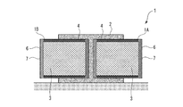
- FIG. 2 is a cross-sectional view of FIG.
- first flexible mandrel 1A and “second flexible mandrel 1 1B ”
- the flexible mandrel 1 is a mold for molding the composite part 2 and has a shape corresponding to the composite part 2 to be molded.
- an aircraft stringer having an I-shaped cross section and having a longitudinally extending shape is shown as an example of the composite part 2.
- the first flexible mandrel 1A and the second flexible mandrel 1B have the same shape, and in FIG. 1, the composite material to be the material of the composite part 2 is placed between them to form It is shown how it will be done.
- the flexible mandrel 1 comprises a main body 3 and a thermally conductive layer 7 formed to cover at least a part of the main body 3.
- the main body 3 is a mold material for molding the composite material part 2 and has a shape corresponding to the composite material part 2 to be molded.
- an aircraft stringer having an I-shaped cross section and having a longitudinally extending shape is shown as an example of the composite part 2.
- the first flexible mandrel 1A and the second flexible mandrel 1B have the same shape, and in FIG. 1, the composite material to be the material of the composite part 2 is placed between them to form It is shown how it will be done.
- the main body 3 of the flexible mandrel 1 is attached to the composite component 2 via the heat conduction layer 7 and the contact surface 4 contacting the composite component 2 via the heat conduction layer 7. It includes a noncontact surface 6 which does not contact.
- the contact surface 4 has a shape corresponding to the composite component 2 for forming the composite component 2 as described above, but the non-contact surface 6 may have any shape.
- the body 3 comprises a first material.
- the first material includes a thermally conductive material in order to transfer the externally supplied heat quantity to the composite component 2 when performing the heat curing process.
- the material of the main body 3 has flexibility which can be deformed according to the specification shape of the composite part 2.
- a composite material CFRP
- PAN-based CFRP that is relatively inexpensive
- the heat conduction layer 7 is formed so as to cover at least a part of the main body 3, and in the present embodiment, in particular, surrounds the entire circumferential direction of the main body 3.
- a heat conductive layer 7 includes a second material having a high thermal conductivity as compared to the first material contained in the main body 3, and as shown in FIG. To the non-contact surface 6. Since a part of the heat conduction layer 7 is exposed to the atmosphere, when the flexible mandrel 1 is heated in the high temperature and high pressure autoclave, the heat from the external atmosphere is transmitted via the heat conduction layer 7. It is transmitted to the composite part 2 in contact with the conductive layer 7. Therefore, compared with the flexible mandrel which does not have the heat conductive layer 7, time required for temperature rising at the time of thermosetting process can be shortened.
- the heat conducting layer 7 is thinner than the main body 3 defining the basic shape of the flexible mandrel 1.
- the thickness of the heat conduction layer 7 is preferably in a range that does not affect the basic shape of the flexible mandrel 1 and is, for example, 2 mm or less.
- PITCH-based CFRP can be used as a second material contained in the heat conduction layer 7, for example.
- PITCH CFRP is more expensive than PAN CFRP
- the heat conduction layer 7 is thinner than the main body 3, so the cost does not increase significantly.
- the thermal conductivity of the PITCH CFRP has anisotropy with respect to the fiber direction, so the fiber direction is from the contact surface 4 to the non-contact surface It is preferable to form in a direction toward 6. Thereby, the heat transfer in the direction from the contact surface 4 toward the non-contact surface 6 is improved, so that the heat transfer from the external atmosphere to the composite component 2 can be more effectively improved.
- PITCH CFRP is excellent in resistance to deformation along the fiber direction. Therefore, by forming the heat conductive layer 7 so that the fiber direction is from the contact surface 4 toward the non-contact surface 6, when the flexible mandrel 1 is deformed, the heat conductive layer 7 is cracked or cracked. It does not occur and can respond flexibly. That is, even when the heat conduction layer 7 is provided on the main body 3, the flexibility of the flexible mandrel 1 can be favorably maintained.
- the heat conduction layer 7 may be formed by thermal spraying a metal material.
- the metal material is higher in rigidity than the above-mentioned PITCH CFRP, but the required flexibility can be secured by forming a sufficiently thin heat conductive layer by thermal spraying.
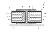
- FIG. 3 is a first modification of FIG.
- the flexible mandrel 1 according to the first modification has at least one hole 8 formed toward the inside of the main body 3.
- a flexible mandrel of this type is typically formed of a solid bulk body, but in this case, the heat capacity of the mandrel body tends to be larger than that of the composite component 2 to be molded, and the thermal It takes time to raise the temperature during the curing process.
- the flexible mandrel 1 according to the first modification since the heat capacity of the flexible mandrel 1 can be reduced by forming the hole 8 in the main body 3, the temperature rise at the time of the thermosetting process is promoted. it can.
- the hole 8 is opened to the non-contact surface 6 of the main body 3. Therefore, the contact state with the composite component 2 is secured on the contact surface 4, and good heat transfer to the composite component 2 becomes possible.
- the hole 8 is formed as a bottomed non-through hole.
- the depth of the hole 8 may be arbitrary, for example, it has a depth of 60% to 90% of the distance L between the contact surface 4 and the non-contact surface 6. By setting the depth of the hole 8 to the above range, the heat capacity of the flexible mandrel 1 can be properly reduced, and good heat conduction to the composite component 2 can be achieved.
- the hole 8 may be formed as a through hole. Although the hole 8 in FIG. 3 has a substantially straight shape, it may have a curved shape, for example, inside the main body 3.
- a plurality of holes 8 are provided.
- the heat capacity is effectively achieved while appropriately securing the flexibility and rigidity of the flexible mandrel 1 as compared with the case where only a single hole 8 is provided. Can be reduced.
- the plurality of holes 8 have a uniform distribution. As described above, in the region where the holes 8 are uniformly distributed, the heat capacity decreases at a constant rate over the entire region, so that heat can be uniformly supplied to the composite at the time of the heat curing treatment, and good quality can be obtained. It becomes possible to form.
- the plurality of holes 8 may be formed unevenly.
- the distribution of the holes 8 may be random, for example, when the flexible mandrel 1 is deformed according to the shape of the composite part 2, a predetermined temperature distribution, stress distribution, etc. are realized. And may be set in accordance with the shape of the composite part 2. As a result, the amount of heat transferred to the composite component 2 can be controlled at the time of heat curing treatment, and molding of high quality can be performed.
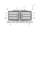
- FIG. 4 is a second modification of FIG.
- the hole 8 in the first modification is filled with the filler 12 containing a material having a thermal conductivity higher than that of the main body 3.
- the thermal conductivity of the main body 3 can be further improved by the filler 12 filled in the holes 8, and the temperature can be raised more quickly.
- a material of the filler 12 for example, a metal foam is useful, and specifically, a material that is lightweight and has excellent thermal conductivity, such as aluminum foam, is preferable.
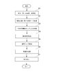
- FIG. 5 is a flowchart showing the method of manufacturing the composite part 2 according to at least one embodiment of the present invention in each step.
- a predetermined material is used to form the main body 3 of the flexible mandrel 1 (step S1).
- the material of the main body 3 has thermal conductivity capable of transferring the amount of heat supplied from the outside to the composite component 2 at the time of the thermosetting process, and according to the specification shape of the composite component 2 It is a material having deformable flexibility, and for example, a composite material (PAN-based CFRP) is used.
- a main body 3 is formed, for example, as a substantially rectangular solid bulk body.
- the heat conduction layer 7 is formed so as to at least partially surround the main body 3 formed in step S1 (step S2).
- the heat conduction layer 7 is formed of a second material having high thermal conductivity, for example, PITCH-based CFRP, as compared to the first material contained in the main body 3.
- the thickness of the heat conduction layer 7 is such that it does not affect the basic shape of the flexible mandrel 1 and is set to, for example, 2 mm or less.
- a material having anisotropy in thermal conductivity such as PITCH CFRP
- the fiber direction is formed from the contact surface 4 toward the non-contact surface 6.
- the heat conduction layer 7 is formed by thermal spraying, for example.
- the hole portion 8 is provided in the main body 3 as in the above-described modified example (see FIGS. 3 and 4), cutting is performed on the main body 3 before forming the heat conduction layer 7 in step S2. It is good to do such machining.
- the hole 8 may be formed at the same time (for example, the main body 3 and the hole 8 may be integrally formed).
- the filler 12 When the filler 12 is filled in the hole 8 formed in the main body 3 as in the second modification described above, the filling operation of the filler 12 is also performed before the heat conductive layer 7 is formed in step S2. Good to be done.
- the filler 12 may comprise a material having a high thermal conductivity as compared to the body 3, for example a metal foam such as aluminum foam can be used.
- step S3 A pair of the above-mentioned flexible mandrels 1 is prepared (step S3), and a composite material to be a material of the composite component 2 is placed between them (step S4).
- the composite used here is, for example, a soft CFRP sheet in a semi-cured state, and is combined according to the shape of the composite part 2.
- FIG. 6 is a schematic view showing a combination pattern of CFRP sheets for forming a composite part 2 having an I-shaped cross section.
- a first sheet 2A covering the contact surface 4 of the first flexible mandrel 1A
- a second flexible Sheet 2B covering the contact surface 4 of the flexible mandrel 1B
- a third sheet 2C covering the first sheet 2A and the second sheet 2B from above
- a fourth sheet covering the first sheet 2A and the second sheet 2B from above
- the sheet 2D of and are combined.
- step S5 the whole is covered with a bag material, and the vacuum bag processing is performed by discharging the air inside.
- a thermosetting process is performed on the pair of flexible mandrels 1 in which the composite material is disposed (step S6).
- the heat curing process is carried out in a high temperature high pressure autoclave. As the ambient temperature within the autoclave increases, the amount of heat transferred through the flexible mandrel 1 heats the composite.
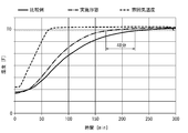
- FIG. 7 is a measurement result which shows time progress of the internal temperature of the flexible mandrel 1 of FIG.1 and FIG.2 at the time of a thermosetting process, and the atmospheric temperature in an autoclave.
- the broken line indicates the ambient temperature in the autoclave, and it is shown that it gradually increases to the target temperature T0 with the passage of time. As the ambient temperature changes in this manner, the internal temperature of the flexible mandrel 1 also increases to follow.
- the measurement result (solid line) is the measurement result according to the comparative example without the heat conductive layer 7 (the same as the flexible mandrel 1 of FIGS.
- the measurement result (dashed-dotted line) is a measurement result according to the flexible mandrel 1 of the present embodiment in which the hole 8 is formed.
- the time to reach the target temperature T0 was about 48 minutes earlier than in the comparative example. This indicates that the flexible mandrel 1 according to this embodiment can be rapidly heated by having the heat conduction layer 7.
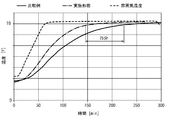
- FIG. 8 is a measurement result showing the time course of the internal temperature of the flexible mandrel 1 of FIG. 3 and the ambient temperature in the autoclave during heat curing.
- the broken line indicates the ambient temperature in the autoclave, and it is shown that it gradually increases to the target temperature T0 with the passage of time. As the ambient temperature changes in this manner, the internal temperature of the flexible mandrel 1 also increases to follow.
- the measurement result (solid line) relates to the measurement according to the comparative example without the heat conduction layer 7 (the same as the flexible mandrel 1 of FIG. 3 except that the heat conduction layer 7 and the hole 8 are not provided).
- a measurement result (dashed dotted line) is a measurement result concerning flexible mandrel 1 of this embodiment in which hole 8 was formed.
- the time to reach the target temperature T0 was about 75 minutes earlier than in the comparative example. This indicates that the flexible mandrel 1 according to the present embodiment can raise its temperature more quickly by having the heat conduction layer 7.
- step S6 the temperature rising to the target temperature is maintained for a predetermined time, whereby the heat curing of the composite material proceeds, and the composite component 2 is molded.
- the thermosetting process is completed, the bag material is released, and the completed composite part 2 is taken out from the inside (step S7).
- the heat capacity of the flexible mandrel is reduced by forming non-through holes in the non-contact surface of the main body of the flexible mandrel, and the thermosetting treatment is performed.
- the time required for temperature rise can be shortened, and good parts production rate and cost reduction can be achieved.
- At least one embodiment of the present invention is applicable to a flexible mandrel used to form a composite part including a composite material such as CFRP, and a method of manufacturing a composite part using the flexible mandrel. is there.
Landscapes
- Engineering & Computer Science (AREA)
- Mechanical Engineering (AREA)
- Manufacturing & Machinery (AREA)
- Chemical & Material Sciences (AREA)
- Composite Materials (AREA)
- Moulding By Coating Moulds (AREA)
- Moulds For Moulding Plastics Or The Like (AREA)
- Casting Or Compression Moulding Of Plastics Or The Like (AREA)
Abstract
可撓性マンドレルは、熱硬化性樹脂を含む複合材を成形するための可撓性マンドレルであって、第1の材料を含む本体(3)と、第1の材料より高い熱伝導率を有する第2の材料を含み、本体の少なくとも一部を覆うように形成された熱伝導層(7)とを備える。熱伝導層は、可撓性マンドレルのうち成形時に複合材に接触する接触面(4)から複合材に接触しない非接触面(6)に至るように延在する。
Description
本開示は、複合材部品を成形するために用いられる可撓性マンドレル及び、当該可撓性マンドレルを用いた複合材部品の製造方法に関する。
炭素繊維強化プラスティック(CFRP:carbon fiber reinforced plastic)に代表される複合材は、一般的な金属材に比べて強度・剛性に優れており、軽量化が要求される航空機や宇宙機器等の構造に多く利用されている。CFRPでは主にエポキシ樹脂のような熱硬化性樹脂が使用されており、複合材を高温高圧のオートクレーブと呼ばれる容器内で熱硬化することにより、成形が行われる。
このような複合材部品の一例として、航空機に使用される板材を補強するためのストリンガがある。ストリンガは機体設計によって輪郭やねじりを含む複雑な形状を有しており、例えばI型の断面形状を有する。このようなストリンガは、型材である一対のマンドレルの間に半硬化状態の柔らかいCFRPシート(複合材)を積層した後に、真空バッグで全体を囲うことで内部の空気を排除し、複合材とマンドレルとを密着させて熱硬化処理を行うことで成形される。
特許文献1では、このようなストリンガを成形するために用いられる金属製のマンドレルにおいて、深さ方向に溝を形成することで良好な可撓性を実現し、複雑な形状(輪郭やねじり)に対応可能であることが開示されている。
上記特許文献1のように熱硬化性樹脂を含む複合材の成形に用いられるマンドレルは、成形対象である複合材に比べて熱容量も大きくなる。そのため、成形対象である複合材に対して熱硬化処理を実施する際に、十分に昇温するために多くの時間を要しており、部品製造レートの低下や、熱硬化処理で消費される電力増加によってコスト増を招く要因となっている。
またストリンガのような複雑な形状を有する複合材部品の成形に用いられるマンドレルは、自身も軽量で可撓性を有するCFRPで形成されることがある。この場合、マンドレル自身の可撓性を確保しながら上記課題を解決する必要がある。
本発明の少なくとも一実施形態は上述の事情に鑑みなされたものであり、良好な可撓性を確保しつつ、熱硬化性樹脂を含む複合材を熱硬化処理時する際の昇温を促進することにより、部品製造レートを向上させ、コスト低減を達成可能な可撓性マンドレル及び複合材部品の製造方法を提供することを目的とする。
(1)本発明の少なくとも一実施形態に係る可撓性マンドレルは上記課題を解決するために、熱硬化性樹脂を含む複合材を成形するための可撓性マンドレルであって、第1の材料を含む本体と、前記第1の材料より高い熱伝導率を有する第2の材料を含み、前記本体の少なくとも一部を覆うように形成された熱伝導層と、を備え、前記熱伝導層は、前記可撓性マンドレルのうち成形時に前記複合材に接触する接触面から前記複合材に接触しない非接触面に至るように延在する。
上記(1)の構成によれば、第1の材料を含む本体部の少なくとも一部は、第1の材料より高い熱伝導率を有する第2の材料を含む熱伝導層によって覆われる。このような熱伝導層は接触面から非接触面に至るように延在するため、熱硬化処理時に外部から供給される熱量は、熱伝導層を介して成形対象である複合材に効果的に伝達される。そのため熱硬化処理に昇温に必要な時間を短縮でき、部品製造レートを向上させ、コスト低減を達成できる。
(2)幾つかの実施形態では上記(1)の構成において、前記熱伝導層は前記本体の周方向全体を囲む。
上記(2)の構成によれば、熱硬化処理時に外部から供給される熱量をより効果的に複合材に伝達できる。
(3)幾つかの実施形態では上記(1)又は(2)の構成において、前記第2の材料はPITCH系CFRPである。
上記(3)の構成によれば、熱伝導層を形成する第2の材料としてPITCH系CFRPが用いられる。PITCH系CFRPは比較的高価な材料であるが、本体に比べて熱伝導層は薄いため、コストを抑えながら効率的な熱伝導を実現できる。
(4)幾つかの実施形態では上記(3)の構成において、前記PITCH系CFRPは前記接触面から前記非接触面に向かう繊維方向を有する。
PITCH系CFRPの熱伝導率は異方性を有しており、繊維方向における熱伝導率が優れている。上記(4)の構成によれば、熱伝導層に含まれるPITCH系CFRPは、繊維方向が接触面から非接触面に向かうため、熱硬化処理の実施時に外部から供給される熱量は、成形対象である複合材に対して良好に伝達される。
(5)幾つかの実施形態では上記(1)又は(2)の構成において、前記第2の材料は金属である。
上記(5)の構成によれば、熱伝導層に含まれる第2の材料として、良好な熱伝導率を有する金属を用いてもよい。この場合、熱伝導層に含まれる金属の厚さは、成形時に要求される可撓性を阻害しないような厚さに設定されるとよい。
(6)幾つかの実施形態では上記(1)から(5)のいずれか一構成において、前記第1の材料はPAN系CFRPである。
上記(6)の構成によれば、可撓性マンドレルの大部分の容積を占める本体を構成する第1の材料として、比較的安価で良好な可撓性を有するPAN系CFRPが用いられる。
(7)幾つかの実施形態では上記(1)から(6)のいずれか一構成において、前記熱伝導層は2mm未満の厚さを有する。
上記(7)の構成によれば、熱伝導層の厚さを上記範囲に設定することで、マンドレルに要求される可撓性を十分に確保しながら、熱伝導層による昇温時間の短縮を達成できる。
(8)幾つかの実施形態では上記(1)から(7)のいずれか一構成において、前記本体には内側に向けて少なくとも一つの穴部が形成される。
上記(8)の構成によれば、可撓性マンドレルの本体に穴部が形成されることにより、可撓性マンドレルの熱容量を低減させられる。これにより、熱硬化処理の昇温に必要な時間を更に短縮できる。
(9)幾つかの実施形態では上記(8)の構成において、前記穴部は前記本体のうち前記非接触面側に設けられる。
上記(9)の構成によれば、成形時に複合材と接触しない非接触面に穴部を設けることで、接触面では複合材との接触状態を確保して良好な熱伝導を確保しつつ、可撓性マンドレルの熱容量を低減することで、熱硬化処理時の昇温時間をより効果的に短縮できる。
(10)幾つかの実施形態では上記(8)又は(9)の構成において、前記穴部を充填する充填材を更に備え、前記充填材は前記第1の材料より高い熱伝導率を有する。
上記(10)の構成によれば、充填材として本体に比べて高い熱伝導率を有する充填剤が穴部に充填されることで、可撓性マンドレルの熱伝導性を更に向上できる。これにより、加熱硬化処理時の昇温を、より迅速に行うことができる。
(11)本発明の少なくとも一実施形態に係る複合材部品の製造方法は上記課題を解決するために、一対の可撓性マンドレルを用いて熱硬化性樹脂を含む複合材を成形することにより、複合材部品を製造するための方法であって、第1の材料を用いて、前記可撓性マンドレルの本体を形成する工程と、前記第1の材料より高い熱伝導率を有する第2の材料を用いて、前記可撓性マンドレルのうち成形時に前記複合材に接触する接触面から前記複合材に接触しない非接触面に至るまで、前記本体の少なくとも一部を覆うように熱伝導層を形成する工程と、前記熱伝導層が形成された前記可撓性マンドレルの間に前記複合材を介在させ、熱硬化処理を実施する工程と、を備える。
上記(11)の方法によれば、上述の可撓性マンドレル(上記各種形態を含む)を用いることで、良好な可撓性を確保しつつ、熱硬化性樹脂を含む複合材に対して熱硬化処理を実施する際に、昇温を促進できる。
(12)幾つかの実施形態では上記(11)の方法において、前記本体に前記熱伝導層を形成する前に、前記本体の内側に向けて穴部を形成する工程を更に備える。
上記(12)の方法によれば、本体に対して穴部を形成した後に熱伝導層を形成することで、熱硬化性樹脂を含む複合材に対して熱硬化処理を実施する際に、より効果的に熱伝導が可能な可撓性マンドレルを製造できる。
(13)幾つかの実施形態では上記(11)又は(12)の方法において、前記熱伝導層は金属材料を溶射することにより形成される。
上記(13)の方法によれば、熱伝導層を金属材料から形成する場合には、溶射を用いることで、マンドレルの仕様として要求される可撓性を有する熱伝導層を好適に形成できる。
本発明の少なくとも一実施形態によれば、良好な可撓性を確保しつつ、熱硬化性樹脂を含む複合材を熱硬化処理時する際の昇温を促進することにより、部品製造レートを向上させ、コスト低減を達成可能な可撓性マンドレル及び複合材部品の製造方法を提供できる。
以下、添付図面を参照して本発明の幾つかの実施形態について説明する。ただし、実施形態として記載されている又は図面に示されている構成部品の寸法、材質、形状、その相対的配置等は、本発明の範囲をこれに限定する趣旨ではなく、単なる説明例にすぎない。
例えば、「ある方向に」、「ある方向に沿って」、「平行」、「直交」、「中心」、「同心」或いは「同軸」等の相対的或いは絶対的な配置を表す表現は、厳密にそのような配置を表すのみならず、公差、若しくは、同じ機能が得られる程度の角度や距離をもって相対的に変位している状態も表すものとする。
また例えば、四角形状や円筒形状等の形状を表す表現は、幾何学的に厳密な意味での四角形状や円筒形状等の形状を表すのみならず、同じ効果が得られる範囲で、凹凸部や面取り部等を含む形状も表すものとする。
一方、一の構成要素を「備える」、「具える」、「具備する」、「含む」、又は、「有する」という表現は、他の構成要素の存在を除外する排他的な表現ではない。
以下の実施形態では、複合材として、炭素繊維を樹脂で強化された炭素繊維強化プラスティック(CFRP:carbon fiber reinforced plastic)であって、主にエポキシ樹脂をはじめ、不飽和ポリエステル、ビニルエステル、フェノール、シアネートエステル、ポリイミドのような熱硬化性樹脂を含むことにより、熱硬化処理によって成形が可能な材料を例に説明する。
尚、複合材の強化繊維は、炭素繊維以外にもガラス繊維、ボロン繊維、アラミド繊維なども同様に適用可能である。
尚、複合材の強化繊維は、炭素繊維以外にもガラス繊維、ボロン繊維、アラミド繊維なども同様に適用可能である。
また以下の実施形態では、複合材を成形することで得られる複合材部品として、航空機に使用される板材を補強するためのストリンガを例示するが、技術的思想が共通する範囲において、種々の部品に適合可能である。特に、強度・剛性とともに軽量化が要求される航空機や宇宙機器等の構造に利用可能である。
(可撓性マンドレル)
まず複合材部品の成形に用いられる可撓性マンドレルの構成について説明する。図1は本発明の少なくとも一実施形態に係る可撓性マンドレル1を示す斜視図であり、図2は図1の断面図である。図1及び図2では、同形状を有する一対の可撓性マンドレル1(以下、それぞれを区別して述べる場合には、それぞれ「第1の可撓性マンドレル1A」及び「第2の可撓性マンドレル1B」と称する)とともに、成形対象物である複合材部品2がともに示されている。
まず複合材部品の成形に用いられる可撓性マンドレルの構成について説明する。図1は本発明の少なくとも一実施形態に係る可撓性マンドレル1を示す斜視図であり、図2は図1の断面図である。図1及び図2では、同形状を有する一対の可撓性マンドレル1(以下、それぞれを区別して述べる場合には、それぞれ「第1の可撓性マンドレル1A」及び「第2の可撓性マンドレル1B」と称する)とともに、成形対象物である複合材部品2がともに示されている。
可撓性マンドレル1は、複合材部品2を成形するための型材であり、成形対象物である複合材部品2に対応する形状を有する。本実施形態では、複合材部品2の一例としてI型断面を有し、長手方向に延在する形状を有する航空機ストリンガが示されている。第1の可撓性マンドレル1A及び第2の可撓性マンドレル1Bは同形状を有しており、図1では、それらの間に複合材部品2の材料となる複合材を配置して成形が行われる様子が示されている。
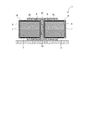
可撓性マンドレル1は、本体3と、本体3の少なくとも一部を覆うように形成された熱伝導層7と、を備える。本体3は、複合材部品2を成形するための型材であり、成形対象物である複合材部品2に対応する形状を有する。本実施形態では、複合材部品2の一例としてI型断面を有し、長手方向に延在する形状を有する航空機ストリンガが示されている。第1の可撓性マンドレル1A及び第2の可撓性マンドレル1Bは同形状を有しており、図1では、それらの間に複合材部品2の材料となる複合材を配置して成形が行われる様子が示されている。
図2に示されるように、可撓性マンドレル1の本体3は、熱伝導層7を介して複合材部品2に接触する接触面4、及び、熱伝導層7を介して複合材部品2に接触しない非接触面6を含む。このうち接触面4は、上述したように、複合材部品2を成形するために複合材部品2に対応する形状を有するが、非接触面6は任意の形状を有してもよい。
本体3は第1の材料を含む。第1の材料は、熱硬化処理を実施する際に、外部から供給される熱量を複合材部品2に対して伝達するために、熱伝導性材料を含む。また本体3の材料は、複合材部品2の仕様形状に応じて変形可能な可撓性を有する。このような第1の材料として、例えば、複合材(CFRP)が使用可能であり、特に、比較的コストが安いPAN系CFRPを用いることができる。
熱伝導層7は、本体3の少なくとも一部を覆うように形成されており、本実施形態では特に、本体3の周方向全体を囲んでいる。このような熱伝導層7は、本体3に含まれる第1の材料に比べて高い熱伝導率を有する第2の材料を含んでおり、図2に示されるように、本体3の接触面4から非接触面6に至るように延在する。熱伝導層7の一部は雰囲気中に露出するため、可撓性マンドレル1が高温高圧のオートクレープ内で加熱された際に、外部雰囲気からの熱量が熱伝導層7を介して、当該熱伝導層7に接触する複合材部品2に伝達される。そのため、熱伝導層7を有さない可撓性マンドレルに比べて、熱硬化処理時の昇温に必要な時間を短縮できる。
熱伝導層7は、可撓性マンドレル1の基本的形状を画定する本体3に比べて薄く形成される。熱伝導層7の厚さは、可撓性マンドレル1の基本的形状に影響を与えない範囲が好ましく、例えば、2mm以下である。また熱伝導層7に含まれる第2の材料として、例えばPITCH系CFRPが使用可能である。PITCH系CFRPは、PAN系CFRPに比べて高価であるが、熱伝導層7は本体3に比べて薄いため、コストが大幅に増加することもない。
熱伝導層7に含まれる第2の材料としてPITCH系CFRPを採用した場合、PITCH系CFRPの熱伝導率は繊維方向に対して異方性を有するため、繊維方向が接触面4から非接触面6に向かう方向になるように形成するとよい。これにより、接触面4から非接触面6に向かう方向における熱伝達が向上するため、外部雰囲気から複合材部品2への熱伝達を、より効果的に向上できる。
またPITCH系CFRPは繊維方向に沿った変形に対する耐久性に優れる。そのため、繊維方向が接触面4から非接触面6に向かう方向になるように熱伝導層7を形成することで、可撓性マンドレル1が変形した際に、熱伝導層7に割れやヒビを生じることがなく、柔軟に対応できる。つまり本体3に熱伝導層7を設けた際においても、可撓性マンドレル1の可撓性を良好に確保できる。
尚、熱伝導層7は金属材料を溶射することにより形成されてもよい。金属材料は上述のPITCH系CFRPに比べて高剛性であるが、溶射によって十分薄い熱伝導層として形成することで、要求される可撓性を確保可能である。
図3は図2の第1変形例である。第1変形例に係る可撓性マンドレル1は、本体3の内側に向けて形成された少なくとも一つの穴部8を有する。この種の可撓性マンドレルは、典型例には、中実のバルク体からなるが、この場合、成形対象物である複合材部品2に比べてマンドレル本体の熱容量が大きくなりがちであり、熱硬化処理時の昇温に時間を要してしまう。その点、第1変形例に係る可撓性マンドレル1では、本体3に穴部8が形成されることで、可撓性マンドレル1の熱容量を低減できるので、熱硬化処理時の昇温を促進できる。
ここで第1変形例では特に、穴部8は本体3のうち非接触面6に開口されている。そのため、接触面4では複合材部品2との接触状態が確保され、複合材部品2に対して良好な熱伝達が可能となる。
穴部8は、有底の非貫通穴として形成されている。穴部8の深さは任意でよいが、例えば、接触面4及び非接触面6間の距離Lの60%~90%の深さを有する。穴部8の深さを当該範囲に設定することで、可撓性マンドレル1の熱容量を的確に低減し、複合材部品2への良好な熱伝導が可能である。
尚、穴部8は貫通穴として形成されてもよい。また図3の穴部8は略ストレート形状を有しているが、例えば本体3の内部において湾曲形状を有してもよい。
また第1変形例では、穴部8は複数設けられている。このように複数の穴部8を設けることにより、穴部8が単一しか設けられていない場合に比べて、可撓性マンドレル1の可撓性及び剛性を的確に確保しつつ、熱容量を効果的に低減できる。
また第1変形例では、複数の穴部8は、均一な分布を有している。このように穴部8が均一に分布する領域では、その領域全体に亘って熱容量が一定の割合で減少するため、熱硬化処理時に複合材に対して均一に熱量を供給でき、良好な品質の成形が可能となる。
尚、複数の穴部8は不均一に形成されていてもよい。この場合、穴部8の分布はランダムでもよいが、例えば可撓性マンドレル1が複合材部品2の形状に応じて変形された際に、所定の温度分布、応力分布等が実現されるように、複合材部品2の形状に応じて設定されてもよい。これにより、熱硬化処理時に、複合材部品2に対して伝達される熱量をコントロールすることができ、良質な品質の成形が可能となる。
図4は図2の第2変形例である。第2変形例では、第1変形例の穴部8に対して、本体3に比べて高い熱伝導率を有する材料を含む充填材12が充填される。穴部8に充填される充填材12によって本体3の熱伝導性を更に向上でき、より迅速な昇温が可能となる。充填材12の材料としては、例えば金属発泡体が有用であり、具体的には発泡アルミニウムのように、軽量であり、且つ、熱伝導率に優れた材料が好ましい。
(複合剤部品の製造方法)
続いて上記構成を有する可撓性マンドレル1を用いた複合材部品2の製造方法について説明する。図5は、本発明の少なくとも一実施形態に係る複合材部品2の製造方法を工程毎に示すフローチャートである。
続いて上記構成を有する可撓性マンドレル1を用いた複合材部品2の製造方法について説明する。図5は、本発明の少なくとも一実施形態に係る複合材部品2の製造方法を工程毎に示すフローチャートである。
まず所定の材料を用いて可撓性マンドレル1の本体3を形成する(ステップS1)。ここで本体3の材料は、上述したように、熱硬化処理時に、外部から供給される熱量を複合材部品2に伝達可能な熱伝導性を有するとともに、複合材部品2の仕様形状に応じて変形可能な可撓性を有する材料であり、例えば、複合材(PAN系CFRP)が用いられる。
このような本体3は、例えば略直方体形状の中実なバルク体として形成される。
このような本体3は、例えば略直方体形状の中実なバルク体として形成される。
続いてステップS1で形成された本体3を少なくとも部分的に囲むように熱伝導層7を形成する(ステップS2)。熱伝導層7は、本体3に含まれる第1の材料に比べて高い熱伝導率を有する第2の材料、例えばPITCH系CFRPから形成される。熱伝導層7の厚さは、可撓性マンドレル1の基本的形状に対して影響を与えない程度であり、例えば、2mm以下に設定される。またPITCH系CFRPのように熱伝導性に異方性を有する材料の場合、繊維方向が接触面4から非接触面6に向かう方向になるように形成される。
尚、第2の材料として金属材料が用いられる場合には、熱伝導層7は例えば溶射によって形成される。
尚、第2の材料として金属材料が用いられる場合には、熱伝導層7は例えば溶射によって形成される。
ここで上述の変形例(図3及び図4を参照)のように、本体3に穴部8を設ける場合には、ステップS2で熱伝導層7を形成する前に、本体3に対して切削のような機械加工を行うとよい。またステップS1で本体3を形成する際に、同時に穴部8を形成してもよい(例えば本体3と穴部8とを一体的に形成してもよい)。
また上述の第2変形例のように、本体3に形成された穴部8に充填材12が充填される場合、充填材12の充填作業もまた、ステップS2で熱伝導層7を形成する前に行われるとよい。充填材12は、本体3に比べて高い熱伝導率を有する材料を含んでもよく、例えば発泡アルミニウムのような金属発泡体が使用可能である。
続いて、このように完成した可撓性マンドレル1を用いて、複合材部品2の成形が進められる。上述の可撓性マンドレル1を一対用意し(ステップS3)、それらの間に複合材部品2の材料となる複合材を配置する(ステップS4)。ここで使用される複合材は、例えば半硬化状態の柔らかなCFRPシートであり、複合材部品2の形状に応じて組み合わされる。
図6はI型断面を有する複合材部品2を成形するためのCFRPシートの組み合わせパターンを示す模式図である。図1に示されるようなI型断面を有する複合材部品2を成形する場合には、例えば、第1の可撓性マンドレル1Aの接触面4を覆う第1シート2Aと、第2の可撓性マンドレル1Bの接触面4を覆う第2シート2Bと、第1シート2A及び第2シート2Bにわたって上方から覆う第3のシート2Cと、第1シート2A及び第2シート2Bにわたって上方から覆う第4のシート2Dと、が組み合わされる。
続いて、一対の可撓性マンドレル1の間に複合材を配置させた状態で、全体をバッグ材で覆い、内部の空気を排出することにより真空バッグ処理を実施する(ステップS5)。続いて真空バッグ処理が施された状態で、複合材が間に配置された一対の可撓性マンドレル1に対して熱硬化処理を行う(ステップS6)。熱硬化処理は高温高圧のオートクレープ内で行われる。オートクレープ内の雰囲気温度が上昇すると、可撓性マンドレル1を介して伝達された熱量によって複合材が加熱される。
ここで図7は、熱硬化処理時における図1及び図2の可撓性マンドレル1の内部温度とオートクレープ内の雰囲気温度の時間経過を示す測定結果である。図7では、破線はオートクレープ内の雰囲気温度を示しており、時間の経過とともに目標温度T0まで次第に増加する様子が示されている。このように雰囲気温度が変化するに従って、可撓性マンドレル1の内部温度も追従するように増加する。測定結果(実線)は熱伝導層7を有さない比較例(熱伝導層7を有さないことを除いて、図1及び図2の可撓性マンドレル1と同一のもの)に係る計測結果であり、測定結果(一点鎖線)は穴部8が形成された本実施形態の可撓性マンドレル1に係る計測結果である。図7に示されるように、本実施形態は比較例に比べて目標温度T0に到達する時間が約48分ほど早い結果が得られた。これは、本実施形態に係る可撓性マンドレル1は熱伝導層7を有することにより、迅速に昇温が可能であることを示している。
また図8は熱硬化処理時における図3の可撓性マンドレル1の内部温度とオートクレープ内の雰囲気温度の時間経過を示す測定結果である。図8では、破線はオートクレープ内の雰囲気温度を示しており、時間の経過とともに目標温度T0まで次第に増加する様子が示されている。このように雰囲気温度が変化するに従って、可撓性マンドレル1の内部温度も追従するように増加する。測定結果(実線)は熱伝導層7を有さない比較例(熱伝導層7及び穴部8を有さないことを除いて、図3の可撓性マンドレル1と同一のもの)に係る計測結果であり、測定結果(一点鎖線)は穴部8が形成された本実施形態の可撓性マンドレル1に係る計測結果である。図8示されるように、本実施形態(図3)は比較例に比べて目標温度T0に到達する時間が約75分ほど早い結果が得られた。これは、本実施形態に係る可撓性マンドレル1は熱伝導層7を有することにより、更に迅速に昇温が可能であることを示している。
ステップS6の熱硬化処理では、このように目標温度に昇温された状態が所定時間維持されることで、複合材の熱硬化が進行し、複合材部品2の成形が行われる。熱硬化処理が完了すると、バッグ材を解放し、内部から完成した複合材部品2が取り出される(ステップS7)。
以上説明したように本発明の少なくとも一実施形態によれば、可撓性マンドレルの本体のうち非接触面に非貫通孔を形成することで、可撓性マンドレルの熱容量を低下させ、熱硬化処理に昇温に必要な時間を短縮でき、良好な部品製造レート及びコスト低減を達成できる。
本発明の少なくとも一実施形態は、CFRP等の複合材を含む複合材部品を成形するために用いられる可撓性マンドレル及び、当該可撓性マンドレルを用いた複合材部品の製造方法に利用可能である。
1 可撓性マンドレル
2 複合材部品
3 本体
4 接触面
6 非接触面
7 熱伝導層
8 穴部
12 充填材
2 複合材部品
3 本体
4 接触面
6 非接触面
7 熱伝導層
8 穴部
12 充填材
Claims (13)
- 熱硬化性樹脂を含む複合材を成形するための可撓性マンドレルであって、
第1の材料を含む本体と、
前記第1の材料より高い熱伝導率を有する第2の材料を含み、前記本体の少なくとも一部を覆うように形成された熱伝導層と、
を備え、
前記熱伝導層は、前記可撓性マンドレルのうち成形時に前記複合材に接触する接触面から前記複合材に接触しない非接触面に至るように延在する、可撓性マンドレル。 - 前記熱伝導層は前記本体の周方向全体を囲む、請求項1に記載の可撓性マンドレル。
- 前記第2の材料はPITCH系CFRPである、請求項1又は2に記載の可撓性マンドレル。
- 前記PITCH系CFRPは前記接触面から前記非接触面に向かう繊維方向を有する、請求項3に記載の可撓性マンドレル。
- 前記第2の材料は金属である、請求項1又は2に記載の可撓性マンドレル。
- 前記第1の材料はPAN系CFRPである、請求項1から5のいずれか一項に記載の可撓性マンドレル。
- 前記熱伝導層は2mm未満の厚さを有する、請求項1から6のいずれか一項に記載の可撓性マンドレル。
- 前記本体には内側に向けて少なくとも一つの穴部が形成される、請求項1から7のいずれか一項に記載の可撓性マンドレル。
- 前記穴部は前記本体のうち前記非接触面側に設けられる、請求項8に記載の可撓性マンドレル。
- 前記穴部を充填する充填材を更に備え、
前記充填材は前記第1の材料より高い熱伝導率を有する、請求項8又は9に記載の可撓性マンドレル。 - 一対の可撓性マンドレルを用いて熱硬化性樹脂を含む複合材を成形することにより、複合材部品を製造するための方法であって、
第1の材料を用いて、前記可撓性マンドレルの本体を形成する工程と、
前記第1の材料より高い熱伝導率を有する第2の材料を用いて、前記可撓性マンドレルのうち成形時に前記複合材に接触する接触面から前記複合材に接触しない非接触面に至るまで、前記本体の少なくとも一部を覆うように熱伝導層を形成する工程と、
前記熱伝導層が形成された前記可撓性マンドレルの間に前記複合材を介在させ、熱硬化処理を実施する工程と、
を備える、複合材部品の製造方法。 - 前記本体に前記熱伝導層を形成する前に、前記本体の内側に向けて穴部を形成する工程を更に備える、請求項11に記載の複合材部品の製造方法。
- 前記熱伝導層は金属材料を溶射することにより形成される、請求項11又は12に記載の複合材部品の製造方法。
Priority Applications (2)
| Application Number | Priority Date | Filing Date | Title |
|---|---|---|---|
| EP18841011.2A EP3620295B1 (en) | 2017-08-03 | 2018-07-13 | Flexible mandrel, and method for producing composite material component |
| US16/624,409 US11584095B2 (en) | 2017-08-03 | 2018-07-13 | Flexible mandrel, and method for producing composite component |
Applications Claiming Priority (2)
| Application Number | Priority Date | Filing Date | Title |
|---|---|---|---|
| JP2017150650A JP6836474B2 (ja) | 2017-08-03 | 2017-08-03 | 可撓性マンドレル、複合材部品の製造方法 |
| JP2017-150650 | 2017-08-03 |
Publications (1)
| Publication Number | Publication Date |
|---|---|
| WO2019026594A1 true WO2019026594A1 (ja) | 2019-02-07 |
Family
ID=65233660
Family Applications (1)
| Application Number | Title | Priority Date | Filing Date |
|---|---|---|---|
| PCT/JP2018/026574 WO2019026594A1 (ja) | 2017-08-03 | 2018-07-13 | 可撓性マンドレル、複合材部品の製造方法 |
Country Status (4)
| Country | Link |
|---|---|
| US (1) | US11584095B2 (ja) |
| EP (1) | EP3620295B1 (ja) |
| JP (1) | JP6836474B2 (ja) |
| WO (1) | WO2019026594A1 (ja) |
Cited By (1)
| Publication number | Priority date | Publication date | Assignee | Title |
|---|---|---|---|---|
| CN111823449A (zh) * | 2020-05-29 | 2020-10-27 | 成都飞机工业(集团)有限责任公司 | 一种用于“λ”型复合材料零件精确制造的软模 |
Families Citing this family (2)
| Publication number | Priority date | Publication date | Assignee | Title |
|---|---|---|---|---|
| DE102020134901A1 (de) | 2020-12-23 | 2022-06-23 | Airbus Operations Gmbh | Formkern zur Herstellung eines Bauteils aus Faserverbundmaterial |
| JP7358425B2 (ja) * | 2021-08-18 | 2023-10-10 | 三菱重工業株式会社 | 複合材の加工装置及び複合材の加工方法 |
Citations (3)
| Publication number | Priority date | Publication date | Assignee | Title |
|---|---|---|---|---|
| JP2008521645A (ja) * | 2004-11-24 | 2008-06-26 | ザ・ボーイング・カンパニー | 高度に成形された複合材ストリンガ用の可撓性マンドレル及び前記ストリンガの製造方法 |
| JP2012131080A (ja) * | 2010-12-20 | 2012-07-12 | Mitsubishi Heavy Ind Ltd | 複合材成形治具 |
| JP2014532000A (ja) * | 2011-10-12 | 2014-12-04 | ザ・ボーイング・カンパニーTheBoeing Company | 軽量可撓性マンドレルおよび軽量可撓性マンドレルを作る方法 |
Family Cites Families (11)
| Publication number | Priority date | Publication date | Assignee | Title |
|---|---|---|---|---|
| FR2658753A1 (fr) * | 1990-02-23 | 1991-08-30 | Snecma | Dispositif de moulage en materiau composite pour le pressage a chaud de pieces en materiau refractaire. |
| US5502886A (en) | 1994-09-02 | 1996-04-02 | The Boeing Company | Composite stringer disassembly machine |
| US5817267A (en) | 1995-11-13 | 1998-10-06 | General Magnaplate Corporation | Fabrication of tooling by thermal spraying |
| JP3384264B2 (ja) | 1996-11-28 | 2003-03-10 | 松下電器産業株式会社 | 熱伝導制御装置及び樹脂成形金型装置 |
| US6447704B1 (en) | 2000-05-23 | 2002-09-10 | Gmic, Corp. | Thermal-sprayed tooling |
| US6743384B2 (en) * | 2001-03-19 | 2004-06-01 | Honeywell International Inc. | Anisotropic heat diffuser plate |
| US8336596B2 (en) * | 2002-11-22 | 2012-12-25 | The Boeing Company | Composite lamination using array of parallel material dispensing heads |
| GB2447964B (en) * | 2007-03-29 | 2012-07-18 | Gurit Uk Ltd | Moulding material |
| JP2008280432A (ja) | 2007-05-10 | 2008-11-20 | Teijin Ltd | 熱伝導性炭素繊維複合シート及びその製造方法 |
| CL2007003772A1 (es) * | 2007-12-21 | 2008-04-25 | Vulco Sa | Procedimiento para la fabricacion de un mandril flexible de poliuretano, que contiene un alma metalica que comprende recubrir con goma un alma metalica, aplicar desmoldante, precalentar el conjunto, curar el poliuretano y enfriar el codo. |
| JP6544993B2 (ja) * | 2014-06-23 | 2019-07-17 | キヤノン株式会社 | 定着用部材の製造装置 |
-
2017
- 2017-08-03 JP JP2017150650A patent/JP6836474B2/ja active Active
-
2018
- 2018-07-13 WO PCT/JP2018/026574 patent/WO2019026594A1/ja unknown
- 2018-07-13 US US16/624,409 patent/US11584095B2/en active Active
- 2018-07-13 EP EP18841011.2A patent/EP3620295B1/en active Active
Patent Citations (4)
| Publication number | Priority date | Publication date | Assignee | Title |
|---|---|---|---|---|
| JP2008521645A (ja) * | 2004-11-24 | 2008-06-26 | ザ・ボーイング・カンパニー | 高度に成形された複合材ストリンガ用の可撓性マンドレル及び前記ストリンガの製造方法 |
| JP4896035B2 (ja) | 2004-11-24 | 2012-03-14 | ザ・ボーイング・カンパニー | 高度に成形された複合材ストリンガ用の可撓性マンドレル及び前記ストリンガの製造方法 |
| JP2012131080A (ja) * | 2010-12-20 | 2012-07-12 | Mitsubishi Heavy Ind Ltd | 複合材成形治具 |
| JP2014532000A (ja) * | 2011-10-12 | 2014-12-04 | ザ・ボーイング・カンパニーTheBoeing Company | 軽量可撓性マンドレルおよび軽量可撓性マンドレルを作る方法 |
Non-Patent Citations (1)
| Title |
|---|
| See also references of EP3620295A4 |
Cited By (1)
| Publication number | Priority date | Publication date | Assignee | Title |
|---|---|---|---|---|
| CN111823449A (zh) * | 2020-05-29 | 2020-10-27 | 成都飞机工业(集团)有限责任公司 | 一种用于“λ”型复合材料零件精确制造的软模 |
Also Published As
| Publication number | Publication date |
|---|---|
| US11584095B2 (en) | 2023-02-21 |
| EP3620295A4 (en) | 2020-06-03 |
| JP2019025870A (ja) | 2019-02-21 |
| US20200180244A1 (en) | 2020-06-11 |
| EP3620295A1 (en) | 2020-03-11 |
| EP3620295B1 (en) | 2021-02-17 |
| JP6836474B2 (ja) | 2021-03-03 |
Similar Documents
| Publication | Publication Date | Title |
|---|---|---|
| WO2019026594A1 (ja) | 可撓性マンドレル、複合材部品の製造方法 | |
| KR102197337B1 (ko) | 안정화 부재를 구비한 복합 구조물 | |
| JP2019073263A (ja) | 航空機の構造的構成要素の強度及び靭性を高めるための方法及び装置 | |
| JP5151668B2 (ja) | Frpの製造方法 | |
| US10688736B2 (en) | Composite materials molding method, and composite materials | |
| CN106079474A (zh) | 一种舰船复合材料螺旋桨叶片预成型体及其制备方法 | |
| WO2019188195A1 (ja) | 繊維強化樹脂の製造方法 | |
| JP6543577B2 (ja) | 複合材の成形方法及び複合材の成形用治具 | |
| JP2020114664A (ja) | 複合部品用の内部ツーリング | |
| JP5709512B2 (ja) | 複合材成形治具および複合材成形治具の製造方法 | |
| JP4941811B2 (ja) | プリフォーム、frp成形体の製造方法 | |
| JP2019217651A (ja) | 複合材料構造体の形成方法 | |
| WO2020122260A1 (ja) | 繊維強化樹脂成形品の製造方法 | |
| CN110104202B (zh) | 使用铰接式芯轴的复合飞机制造工具 | |
| WO2012090469A1 (ja) | 成形型 | |
| JP6971690B2 (ja) | 可撓性マンドレル、複合材部品の製造方法 | |
| KR102274173B1 (ko) | 보강재를 통한 복합재료 동시경화 방법 및 그 복합재료 | |
| US20240025136A1 (en) | Method for manufacturing joined body | |
| CN108215440B (zh) | 阶梯状或空心状蜂窝夹层结构的制作方法 | |
| TR2021021194A2 (tr) | Bir üretim sistemi. |
Legal Events
| Date | Code | Title | Description |
|---|---|---|---|
| 121 | Ep: the epo has been informed by wipo that ep was designated in this application |
Ref document number: 18841011 Country of ref document: EP Kind code of ref document: A1 |
|
| ENP | Entry into the national phase |
Ref document number: 2018841011 Country of ref document: EP Effective date: 20191203 |
|
| NENP | Non-entry into the national phase |
Ref country code: DE |