EP3620295B1 - Flexible mandrel, and method for producing composite material component - Google Patents
Flexible mandrel, and method for producing composite material component Download PDFInfo
- Publication number
- EP3620295B1 EP3620295B1 EP18841011.2A EP18841011A EP3620295B1 EP 3620295 B1 EP3620295 B1 EP 3620295B1 EP 18841011 A EP18841011 A EP 18841011A EP 3620295 B1 EP3620295 B1 EP 3620295B1
- Authority
- EP
- European Patent Office
- Prior art keywords
- conductive layer
- thermally conductive
- main body
- flexible mandrel
- contacting surface
- Prior art date
- Legal status (The legal status is an assumption and is not a legal conclusion. Google has not performed a legal analysis and makes no representation as to the accuracy of the status listed.)
- Active
Links
- 239000002131 composite material Substances 0.000 title claims description 101
- 238000004519 manufacturing process Methods 0.000 title claims description 18
- 239000000463 material Substances 0.000 claims description 61
- 239000004918 carbon fiber reinforced polymer Substances 0.000 claims description 39
- 238000000034 method Methods 0.000 claims description 38
- 238000000465 moulding Methods 0.000 claims description 34
- 239000000835 fiber Substances 0.000 claims description 13
- 229920005989 resin Polymers 0.000 claims description 12
- 239000011347 resin Substances 0.000 claims description 12
- 229920001187 thermosetting polymer Polymers 0.000 claims description 11
- 238000012986 modification Methods 0.000 description 13
- 230000004048 modification Effects 0.000 description 13
- 238000005259 measurement Methods 0.000 description 12
- 230000007423 decrease Effects 0.000 description 6
- 239000007769 metal material Substances 0.000 description 5
- 230000000052 comparative effect Effects 0.000 description 4
- 238000009826 distribution Methods 0.000 description 4
- 230000003247 decreasing effect Effects 0.000 description 3
- 230000035515 penetration Effects 0.000 description 3
- 238000005507 spraying Methods 0.000 description 3
- 229920000049 Carbon (fiber) Polymers 0.000 description 2
- 229910052782 aluminium Inorganic materials 0.000 description 2
- XAGFODPZIPBFFR-UHFFFAOYSA-N aluminium Chemical compound [Al] XAGFODPZIPBFFR-UHFFFAOYSA-N 0.000 description 2
- 230000005540 biological transmission Effects 0.000 description 2
- 239000004917 carbon fiber Substances 0.000 description 2
- 238000010586 diagram Methods 0.000 description 2
- 230000000694 effects Effects 0.000 description 2
- 239000003822 epoxy resin Substances 0.000 description 2
- 239000006262 metallic foam Substances 0.000 description 2
- VNWKTOKETHGBQD-UHFFFAOYSA-N methane Chemical compound C VNWKTOKETHGBQD-UHFFFAOYSA-N 0.000 description 2
- 229920000647 polyepoxide Polymers 0.000 description 2
- 230000003014 reinforcing effect Effects 0.000 description 2
- 239000007787 solid Substances 0.000 description 2
- ZOXJGFHDIHLPTG-UHFFFAOYSA-N Boron Chemical compound [B] ZOXJGFHDIHLPTG-UHFFFAOYSA-N 0.000 description 1
- 229910001374 Invar Inorganic materials 0.000 description 1
- ISWSIDIOOBJBQZ-UHFFFAOYSA-N Phenol Chemical compound OC1=CC=CC=C1 ISWSIDIOOBJBQZ-UHFFFAOYSA-N 0.000 description 1
- 239000004642 Polyimide Substances 0.000 description 1
- 229920006231 aramid fiber Polymers 0.000 description 1
- 229910052796 boron Inorganic materials 0.000 description 1
- 239000004020 conductor Substances 0.000 description 1
- 238000005520 cutting process Methods 0.000 description 1
- 239000004643 cyanate ester Substances 0.000 description 1
- 238000013461 design Methods 0.000 description 1
- 230000005611 electricity Effects 0.000 description 1
- 239000000945 filler Substances 0.000 description 1
- 239000006260 foam Substances 0.000 description 1
- 239000003365 glass fiber Substances 0.000 description 1
- 238000010438 heat treatment Methods 0.000 description 1
- 239000003562 lightweight material Substances 0.000 description 1
- 229910052751 metal Inorganic materials 0.000 description 1
- 239000002184 metal Substances 0.000 description 1
- 229920001721 polyimide Polymers 0.000 description 1
- 238000012545 processing Methods 0.000 description 1
- 238000009827 uniform distribution Methods 0.000 description 1
- 229920006305 unsaturated polyester Polymers 0.000 description 1
- 229920001567 vinyl ester resin Polymers 0.000 description 1
Images


Classifications
-
- B—PERFORMING OPERATIONS; TRANSPORTING
- B29—WORKING OF PLASTICS; WORKING OF SUBSTANCES IN A PLASTIC STATE IN GENERAL
- B29C—SHAPING OR JOINING OF PLASTICS; SHAPING OF MATERIAL IN A PLASTIC STATE, NOT OTHERWISE PROVIDED FOR; AFTER-TREATMENT OF THE SHAPED PRODUCTS, e.g. REPAIRING
- B29C70/00—Shaping composites, i.e. plastics material comprising reinforcements, fillers or preformed parts, e.g. inserts
- B29C70/04—Shaping composites, i.e. plastics material comprising reinforcements, fillers or preformed parts, e.g. inserts comprising reinforcements only, e.g. self-reinforcing plastics
- B29C70/28—Shaping operations therefor
- B29C70/40—Shaping or impregnating by compression not applied
- B29C70/42—Shaping or impregnating by compression not applied for producing articles of definite length, i.e. discrete articles
- B29C70/44—Shaping or impregnating by compression not applied for producing articles of definite length, i.e. discrete articles using isostatic pressure, e.g. pressure difference-moulding, vacuum bag-moulding, autoclave-moulding or expanding rubber-moulding
-
- B—PERFORMING OPERATIONS; TRANSPORTING
- B29—WORKING OF PLASTICS; WORKING OF SUBSTANCES IN A PLASTIC STATE IN GENERAL
- B29C—SHAPING OR JOINING OF PLASTICS; SHAPING OF MATERIAL IN A PLASTIC STATE, NOT OTHERWISE PROVIDED FOR; AFTER-TREATMENT OF THE SHAPED PRODUCTS, e.g. REPAIRING
- B29C33/00—Moulds or cores; Details thereof or accessories therefor
- B29C33/38—Moulds or cores; Details thereof or accessories therefor characterised by the material or the manufacturing process
- B29C33/3828—Moulds made of at least two different materials having different thermal conductivities
-
- B—PERFORMING OPERATIONS; TRANSPORTING
- B29—WORKING OF PLASTICS; WORKING OF SUBSTANCES IN A PLASTIC STATE IN GENERAL
- B29C—SHAPING OR JOINING OF PLASTICS; SHAPING OF MATERIAL IN A PLASTIC STATE, NOT OTHERWISE PROVIDED FOR; AFTER-TREATMENT OF THE SHAPED PRODUCTS, e.g. REPAIRING
- B29C33/00—Moulds or cores; Details thereof or accessories therefor
- B29C33/38—Moulds or cores; Details thereof or accessories therefor characterised by the material or the manufacturing process
- B29C33/3842—Manufacturing moulds, e.g. shaping the mould surface by machining
-
- B—PERFORMING OPERATIONS; TRANSPORTING
- B29—WORKING OF PLASTICS; WORKING OF SUBSTANCES IN A PLASTIC STATE IN GENERAL
- B29C—SHAPING OR JOINING OF PLASTICS; SHAPING OF MATERIAL IN A PLASTIC STATE, NOT OTHERWISE PROVIDED FOR; AFTER-TREATMENT OF THE SHAPED PRODUCTS, e.g. REPAIRING
- B29C33/00—Moulds or cores; Details thereof or accessories therefor
- B29C33/76—Cores
-
- B—PERFORMING OPERATIONS; TRANSPORTING
- B29—WORKING OF PLASTICS; WORKING OF SUBSTANCES IN A PLASTIC STATE IN GENERAL
- B29C—SHAPING OR JOINING OF PLASTICS; SHAPING OF MATERIAL IN A PLASTIC STATE, NOT OTHERWISE PROVIDED FOR; AFTER-TREATMENT OF THE SHAPED PRODUCTS, e.g. REPAIRING
- B29C43/00—Compression moulding, i.e. applying external pressure to flow the moulding material; Apparatus therefor
- B29C43/02—Compression moulding, i.e. applying external pressure to flow the moulding material; Apparatus therefor of articles of definite length, i.e. discrete articles
- B29C43/10—Isostatic pressing, i.e. using non-rigid pressure-exerting members against rigid parts or dies
- B29C43/12—Isostatic pressing, i.e. using non-rigid pressure-exerting members against rigid parts or dies using bags surrounding the moulding material or using membranes contacting the moulding material
-
- B—PERFORMING OPERATIONS; TRANSPORTING
- B29—WORKING OF PLASTICS; WORKING OF SUBSTANCES IN A PLASTIC STATE IN GENERAL
- B29C—SHAPING OR JOINING OF PLASTICS; SHAPING OF MATERIAL IN A PLASTIC STATE, NOT OTHERWISE PROVIDED FOR; AFTER-TREATMENT OF THE SHAPED PRODUCTS, e.g. REPAIRING
- B29C43/00—Compression moulding, i.e. applying external pressure to flow the moulding material; Apparatus therefor
- B29C43/32—Component parts, details or accessories; Auxiliary operations
- B29C43/36—Moulds for making articles of definite length, i.e. discrete articles
-
- B—PERFORMING OPERATIONS; TRANSPORTING
- B29—WORKING OF PLASTICS; WORKING OF SUBSTANCES IN A PLASTIC STATE IN GENERAL
- B29D—PRODUCING PARTICULAR ARTICLES FROM PLASTICS OR FROM SUBSTANCES IN A PLASTIC STATE
- B29D99/00—Subject matter not provided for in other groups of this subclass
- B29D99/0003—Producing profiled members, e.g. beams
-
- B—PERFORMING OPERATIONS; TRANSPORTING
- B29—WORKING OF PLASTICS; WORKING OF SUBSTANCES IN A PLASTIC STATE IN GENERAL
- B29K—INDEXING SCHEME ASSOCIATED WITH SUBCLASSES B29B, B29C OR B29D, RELATING TO MOULDING MATERIALS OR TO MATERIALS FOR MOULDS, REINFORCEMENTS, FILLERS OR PREFORMED PARTS, e.g. INSERTS
- B29K2663/00—Use of EP, i.e. epoxy resins or derivatives thereof for preformed parts, e.g. for inserts
-
- B—PERFORMING OPERATIONS; TRANSPORTING
- B29—WORKING OF PLASTICS; WORKING OF SUBSTANCES IN A PLASTIC STATE IN GENERAL
- B29K—INDEXING SCHEME ASSOCIATED WITH SUBCLASSES B29B, B29C OR B29D, RELATING TO MOULDING MATERIALS OR TO MATERIALS FOR MOULDS, REINFORCEMENTS, FILLERS OR PREFORMED PARTS, e.g. INSERTS
- B29K2705/00—Use of metals, their alloys or their compounds, for preformed parts, e.g. for inserts
-
- B—PERFORMING OPERATIONS; TRANSPORTING
- B29—WORKING OF PLASTICS; WORKING OF SUBSTANCES IN A PLASTIC STATE IN GENERAL
- B29L—INDEXING SCHEME ASSOCIATED WITH SUBCLASS B29C, RELATING TO PARTICULAR ARTICLES
- B29L2031/00—Other particular articles
- B29L2031/757—Moulds, cores, dies
Definitions
- the present disclosure relates to a flexible mandrel used for molding composite components and a method for producing composite components using the flexible mandrel.
- CFRP carbon fiber reinforced plastic
- a stringer for reinforcing a sheet member used in aircrafts.
- a stringer has a complex shape including a contour and a twist according to airframe design and has an I-type cross-sectional shape, for example.
- Such a stringer is molded in such a way that after a semi-cured soft CFRP sheet (a composite material) is stacked between a pair of mandrels which is a mold, an entire assembly is surrounded by a vacuum bag to exhaust air included therein and a curing process is performed in a state where the composite material is in close contact with the mandrels.
- JP 4896035 B discloses that by forming a groove in a depth direction of a metallic mandrel used for molding such a stringer, it is possible to realize satisfactory flexibility and cope with a complex shape (a contour or a twist).
- US 2013/092323 A1 corresponding to the preamble of claim 1, discloses a flexible mandrel on which the preamble portion of claim 1 is based.
- the mandrel has an outer sleeve that is U-shaped in a cross section to define an elongated inner cavity and a generally flexible inner core which fills the inner cavity.
- the outer sleeve has one or more flexible portions along its length that allow the sleeve to flex.
- the material of the flexible inner core may be inter alia a CFRP.
- the material of the outer sleeve may be Invar (registered trademark) metal.
- a mandrel used for molding a composite material containing a thermosetting resin as in JP 4896035 B has a larger heat capacity than the composite material which is a molding target. Due to this, when a curing process is performed on a composite material which is a molding target, a considerable amount of time is required for increasing the temperature sufficiently, which results in an increase in cost due to decrease in a component production rate and increase in the electricity consumed by the curing process.
- a mandrel itself used for molding a composite component having a complex shape like a stringer is sometimes formed of light-weight and flexible CFRP. In this case, it is necessary to solve the above-described problems while securing flexibility of the mandrel itself.
- the present invention has been made in view of the above-described problems, and an object thereof is to provide a flexible mandrel and method for producing composite components, capable of improving a component production rate and decreasing the cost by accelerating temperature rise during curing of composite materials containing a thermosetting resin while securing satisfactory flexibility.
- thermosetting resin by forming the thermally conductive layer after forming the hole in the main body, it is possible to produce a flexible mandrel capable of transmitting heat more effectively when performing a curing process on a composite material containing a thermosetting resin.
- the present invention it is possible to provide a flexible mandrel and method for producing composite components, capable of improving a component production rate and decreasing the cost by accelerating temperature rise during curing of composite materials containing a thermosetting resin while securing satisfactory flexibility.
- an expression of relative or absolute arrangement such as “in a direction”, “along a direction”, “parallel”, “orthogonal”, “centered”, “concentric” and “coaxial” shall not be construed as indicating only the arrangement in a strict literal sense, but also includes a state where the arrangement is relatively displaced by a tolerance, or by an angle or a distance whereby it is possible to achieve the same function.
- an expression of a shape such as a rectangular shape or a cylindrical shape shall not be construed as only the geometrically strict shape, but also includes a shape with unevenness or chamfered corners within the range in which the same effect can be achieved.
- CFRP carbon fiber reinforced plastic
- a glass fiber, a boron fiber, an aramid fiber, and the like in addition to the carbon fiber can be similarly used as the reinforced fiber of a composite material.
- a stringer for reinforcing a sheet member used in aircrafts is illustrated as a composite component obtained by molding a composite material
- the composite component can be used in various components within the scope of the same technical idea.
- the composite component can be used in structures of aircrafts, space apparatuses, and the like requiring light weight as well as strength and rigidity.
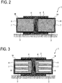
- FIG. 1 is a perspective view illustrating a flexible mandrel 1 according to at least one embodiment of the present invention and FIG. 2 is a cross-sectional view of FIG. 1.
- FIGS. 1 and 2 illustrate a composite component 2 which is a molding target object together with a pair of flexible mandrels 1 having the same shape (hereinafter, the respective flexible mandrels will be referred to as a "first flexible mandrel 1A" and a “second flexible mandrel 1B", respectively, when they are distinguished from each other).
- the flexible mandrel 1 is a mold for molding the composite component 2 and has a shape corresponding to the composite component 2 which is a molding target object.
- an aircraft stringer having an I-type cross-section and a shape extending in a longitudinal direction is illustrated as an example of the composite component 2.
- the first flexible mandrel 1A and the second flexible mandrel 1B have the same shape, and FIG. 1 illustrates a state in which a composite material serving as a material of the composite component 2 is disposed between the flexible mandrels and molding is performed.
- the flexible mandrel 1 includes a main body 3 and a thermally conductive layer 7 formed so as to cover at least a portion of the main body 3.
- the main body 3 is a mold for molding the composite component 2 and has a shape corresponding to the composite component 2 which is a molding target object.
- an aircraft stringer having an I-type cross-section and a shape extending in a longitudinal direction is illustrated as an example of the composite component 2.
- the first flexible mandrel 1A and the second flexible mandrel 1B have the same shape, and FIG. 1 illustrates a state in which a composite material serving as a material of the composite component 2 is disposed between the flexible mandrels and molding is performed.
- the main body 3 of the flexible mandrel 1 includes a contacting surface 4 that comes into contact with the composite component 2 with the thermally conductive layer 7 disposed therebetween and a non-contacting surface 6 that does not come into contact with the composite component 2 with the thermally conductive layer 7 disposed therebetween.
- the contacting surface 4 has a shape corresponding to the composite component 2 in order to mold the composite component 2 as described above, the non-contacting surface 6 may have an arbitrary shape.
- the main body 3 contains a first material.
- the first material contains a thermally conductive material in order to transmit heat supplied from the outside to the composite component 2 when performing a curing process.
- the material of the main body 3 has such flexibility that the main body 3 can be deformed according to a specification shape of the composite component 2.
- a composite material CFRP
- PAN-based CFRP which is relatively inexpensive can be used.
- the thermally conductive layer 7 is formed so as to cover at least a portion of the main body 3, and in the present embodiment, the thermally conductive layer 7 surrounds the entire circumferential direction of the main body 3 particularly.
- Such a thermally conductive layer 7 contains a second material having a higher thermal conductivity than the first material contained in the main body 3 and as illustrated in FIG. 2 , extends from a contacting surface 4 of the main body 3 to a non-contacting surface 6.
- the thermally conductive layer 7 Since a portion of the thermally conductive layer 7 is exposed to the atmosphere, when the flexible mandrel 1 is heated in a high-temperature and high-pressure autoclave, the heat from an external atmosphere is transmitted to the composite component 2 that makes contact with the thermally conductive layer 7 with the thermally conductive layer 7 disposed therebetween. Therefore, it is possible to shorten the time required for increasing the temperature during a curing process as compared to a flexible mandrel that does not have the thermally conductive layer 7.
- the thermally conductive layer 7 is formed to be thinner than the main body 3 that determines a basic shape of the flexible mandrel 1.
- the thickness of the thermally conductive layer 7 is preferably in such a range that does not affect a basic shape of the flexible mandrel 1 and is 2 mm or smaller, for example.
- a PITCH-based CFRP is used as the second material contained in the thermally conductive layer 7. Although the PITCH-based CFRP is more expensive than the PAN-based CFRP, since the thermally conductive layer 7 is thinner than the main body 3, the cost may not increase remarkably.
- the thermally conductive layer 7 is formed so that the fiber direction extends in a direction from the contacting surface 4 toward the non-contacting surface 6. By doing so, since heat transmission in the direction from the contacting surface 4 toward the non-contacting surface 6 is improved, it is possible to improve heat transmission from an external atmosphere toward the composite component 2 more effectively.
- a PITCH-based CFRP exhibits excellent durability against deformation in a fiber direction. Therefore, by forming the thermally conductive layer 7 so that the fiber direction extends in a direction from the contacting surface 4 toward the non-contacting surface 6, the thermally conductive layer 7 will not break or crack when the flexible mandrel 1 is deformed, and it is possible to flexibly cope with the deformation. That is, even when the thermally conductive layer 7 is provided in the main body 3, it is possible to secure flexibility of the flexible mandrel 1 satisfactorily.
- the thermally conductive layer 7 may be formed by spraying a metallic material (not according to the invention as claimed). Although a metallic material has higher rigidity than the PITCH-based CFRP, required flexibility can be secured by forming the metallic material as a sufficiently thin thermally conductive layer by spraying.
- FIG. 3 is a first modification of FIG. 2 .
- a flexible mandrel 1 according to the first modification has at least one hole 8 formed toward an inner side of the main body 3.
- a flexible mandrel of this type is formed of a solid bulk member.
- the heat capacity of a mandrel body is likely to increase as compared to the composite component 2 which is a molding target object and a considerable amount of time is required for increasing temperature during a curing process.
- the flexible mandrel 1 according to the first modification by forming the hole 8 in the main body 3, since it is possible to decrease heat capacity of the flexible mandrel 1, it is possible to accelerate an increase in temperature during a curing process.
- the hole 8 is formed in the non-contacting surface 6 of the main body 3. Therefore, a contact state between the composite component 2 and the contacting surface 4 is secured, and heat can be transmitted to the composite component 2 satisfactorily.
- the hole 8 is formed as a bottomed non-penetration hole.
- the depth of the hole 8 is arbitrary, the hole 8 has a depth that is 60% to 90% of the distance L between the contacting surface 4 and the non-contacting surface 6, for example. By setting the depth of the hole 8 to that range, it is possible to decrease the heat capacity of the flexible mandrel 1 appropriately and transmit heat to the composite component 2 satisfactorily.
- the hole 8 may be formed as a penetration hole. Although the hole 8 in FIG. 3 has an approximately straight shape, the hole 8 may have a curved shape inside the main body 3, for example.
- a plurality of holes 8 is provided.
- a plurality of holes 8 have a uniform distribution.
- the heat capacity decreases in a constant ratio in the entire region, it is possible to supply heat uniformly to the composite material during a curing process and realize molding with satisfactory quality.
- a plurality of holes 8 may be formed non-uniformly.
- the distribution of the holes 8 may be random, when the flexible mandrel 1 is deformed according to the shape of the composite component 2, for example, the distribution may be set according to the shape of the composite component 2 so that a predetermined temperature distribution, a stress distribution, and the like are realized. In this way, it is possible to control the heat transmitted to the composite component 2 during a curing process and realize molding with satisfactory quality.
- FIG. 4 is a second modification of FIG. 2 .
- a filling material 12 containing a material having a higher thermal conductivity than the main body 3 is filled in the hole 8 of the first modification. Due to the filling material 12 filled in the hole 8, it is possible to further improve the thermal conductivity of the main body 3 and increase the temperature more quickly.
- a material of the filling material 12 a metal foam, for example, is useful, and specifically, a light-weight material having an excellent thermal conductivity like an aluminum foam is preferred.
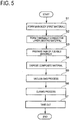
- FIG. 5 is a flowchart illustrating each step of a method for producing the composite component 2 according to at least one embodiment of the present invention.
- the main body 3 of the flexible mandrel 1 is formed using a predetermined material (step S1).
- the material of the main body 3 is a material having a thermal conductivity capable of transmitting heat supplied from the outside to the composite component 2 during a curing process and flexibility capable of deforming according to the specification shape of the composite component 2, and for example, a composite material (a PAN-based CFRP) is used.
- a main body 3 is formed as an approximately rectangular parallelepiped solid bulk body, for example.
- the thermally conductive layer 7 is formed so as to at least partially surround the main body 3 formed in step S1 (step S2).
- the thermally conductive layer 7 is formed from a second material that is a PITCH-based CFRP) having a higher thermal conductivity than the first material contained in the main body 3.
- the thickness of the thermally conductive layer 7 is set to such an extent (for example, 2 mm or smaller) that does not affect a basic shape of the flexible mandrel 1.
- the thermally conductive layer 7 is formed so that a fiber direction thereof extends in a direction from the contacting surface 4 toward the non-contacting surface 6.
- the thermally conductive layer 7 is formed by spraying, for example.
- the hole 8 when the hole 8 is provided in the main body 3 as in the above-described modifications (see FIGS. 3 and 4 ), mechanical processing such as cutting may be performed on the main body 3 before the thermally conductive layer 7 is formed in step S2. Moreover, the hole 8 may be formed simultaneously with forming of the main body 3 in step S1 (for example, the main body 3 and the hole 8 may be formed integrally).
- the operation of filling the filling material 12 may also be performed before forming the thermally conductive layer 7 in step S2.
- the filling material 12 may contain a material having a higher thermal conductivity than the main body 3, and a metal foam such as, for example, a foamed aluminum can be used.
- a pair of flexible mandrels 1 is prepared (step S3), and a composite material serving as a material of the composite component 2 is disposed between the flexible mandrels 1 (step S4).
- the composite material used herein is a semi-cured soft CFRP sheet, for example, and is combined according to the shape of the composite component 2.
- FIG. 6 is a schematic diagram illustrating a combination pattern of CFRP sheets for molding the composite component 2 having an I-type cross-section.
- a first sheet 2A covering the contacting surface 4 of a first flexible mandrel 1A
- a second sheet 2B covering the contacting surface 4 of a second flexible mandrel 1B
- a third sheet 2C covering the first and second sheets 2A and 2B from the upper side
- a fourth sheet 2D covering the first and second sheets 2A and 2B from the upper side are combined together.
- a vacuum bag process is performed in such a way that the entire assembly is covered by a bag to exhaust the air included therein (step S5).
- a curing process is performed on the pair of flexible mandrels 1 having the composite material disposed therebetween (step S6).
- a curing process is performed in a high-temperature and high-pressure autoclave. When the ambient temperature in the autoclave increases, the composite material is heated by the heat transmitted via the flexible mandrel 1.
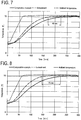
- FIG. 7 is measurement results showing an internal temperature of the flexible mandrel 1 illustrated in FIGS. 1 and 2 during a curing process and an ambient temperature inside an autoclave with the lapse of time.
- a broken line indicates an ambient temperature in the autoclave and illustrates a state in which the ambient temperature increases gradually up to a target temperature TO with the elapse of time.
- the internal temperature of the flexible mandrel 1 increases as the ambient temperature changes.
- a measurement result (a solid line) is a measurement result related to a comparative example (the same flexible mandrel as the flexible mandrel 1 of FIGS.
- a measurement result (a one-dot chain line) is a measurement result related to the flexible mandrel 1 of the present embodiment in which the hole 8 is formed.
- the time at which the target temperature TO is reached is approximately 48 minutes faster than the comparative example. This means that the temperature of the flexible mandrel 1 according to the present embodiment can be increased quickly due to the thermally conductive layer 7.
- FIG. 8 is measurement results showing an internal temperature of the flexible mandrel 1 illustrated in FIG. 3 during a curing process and an ambient temperature inside an autoclave with the lapse of time.
- a broken line indicates an ambient temperature in the autoclave and illustrates a state in which the ambient temperature increases gradually up to a target temperature TO with the elapse of time.
- the internal temperature of the flexible mandrel 1 increases as the ambient temperature changes.
- a measurement result (a solid line) is a measurement result related to a comparative example (the same flexible mandrel as the flexible mandrel 1 of FIG.
- a measurement result (a one-dot chain line) is a measurement result related to the flexible mandrel 1 of the present embodiment in which the hole 8 is formed.
- the time at which the target temperature T0 is reached is approximately 75 minutes faster than the comparative example. This means that the temperature of the flexible mandrel 1 according to the present embodiment can be increased more quickly due to the thermally conductive layer 7.
- step S6 since a state in which the temperature is increased up to the target temperature is maintained for a predetermined period, curing of the composite material progresses and molding of the composite component 2 is performed.
- step S7 the bag is removed and the obtained composite component 2 is taken out of the bag (step S7).
- the present invention it is possible to decrease the heat capacity of a flexible mandrel by forming a non-penetration hole in a non-contacting surface of a main body of the flexible mandrel to shorten the time required for increasing the temperature during a curing process and achieve a satisfactory component production rate and a cost reduction.
- At least one embodiment of the present invention can be used in a flexible mandrel used for molding a composite component containing a composite material such as CFRP and a method for producing a composite component using the flexible mandrel.
Landscapes
- Engineering & Computer Science (AREA)
- Mechanical Engineering (AREA)
- Manufacturing & Machinery (AREA)
- Chemical & Material Sciences (AREA)
- Composite Materials (AREA)
- Moulding By Coating Moulds (AREA)
- Moulds For Moulding Plastics Or The Like (AREA)
- Casting Or Compression Moulding Of Plastics Or The Like (AREA)
Applications Claiming Priority (2)
| Application Number | Priority Date | Filing Date | Title |
|---|---|---|---|
| JP2017150650A JP6836474B2 (ja) | 2017-08-03 | 2017-08-03 | 可撓性マンドレル、複合材部品の製造方法 |
| PCT/JP2018/026574 WO2019026594A1 (ja) | 2017-08-03 | 2018-07-13 | 可撓性マンドレル、複合材部品の製造方法 |
Publications (3)
| Publication Number | Publication Date |
|---|---|
| EP3620295A1 EP3620295A1 (en) | 2020-03-11 |
| EP3620295A4 EP3620295A4 (en) | 2020-06-03 |
| EP3620295B1 true EP3620295B1 (en) | 2021-02-17 |
Family
ID=65233660
Family Applications (1)
| Application Number | Title | Priority Date | Filing Date |
|---|---|---|---|
| EP18841011.2A Active EP3620295B1 (en) | 2017-08-03 | 2018-07-13 | Flexible mandrel, and method for producing composite material component |
Country Status (4)
| Country | Link |
|---|---|
| US (1) | US11584095B2 (ja) |
| EP (1) | EP3620295B1 (ja) |
| JP (1) | JP6836474B2 (ja) |
| WO (1) | WO2019026594A1 (ja) |
Families Citing this family (3)
| Publication number | Priority date | Publication date | Assignee | Title |
|---|---|---|---|---|
| CN111823449A (zh) * | 2020-05-29 | 2020-10-27 | 成都飞机工业(集团)有限责任公司 | 一种用于“λ”型复合材料零件精确制造的软模 |
| DE102020134901A1 (de) | 2020-12-23 | 2022-06-23 | Airbus Operations Gmbh | Formkern zur Herstellung eines Bauteils aus Faserverbundmaterial |
| JP7358425B2 (ja) * | 2021-08-18 | 2023-10-10 | 三菱重工業株式会社 | 複合材の加工装置及び複合材の加工方法 |
Family Cites Families (14)
| Publication number | Priority date | Publication date | Assignee | Title |
|---|---|---|---|---|
| FR2658753A1 (fr) * | 1990-02-23 | 1991-08-30 | Snecma | Dispositif de moulage en materiau composite pour le pressage a chaud de pieces en materiau refractaire. |
| US5502886A (en) | 1994-09-02 | 1996-04-02 | The Boeing Company | Composite stringer disassembly machine |
| US5817267A (en) | 1995-11-13 | 1998-10-06 | General Magnaplate Corporation | Fabrication of tooling by thermal spraying |
| JP3384264B2 (ja) | 1996-11-28 | 2003-03-10 | 松下電器産業株式会社 | 熱伝導制御装置及び樹脂成形金型装置 |
| US6447704B1 (en) | 2000-05-23 | 2002-09-10 | Gmic, Corp. | Thermal-sprayed tooling |
| US6743384B2 (en) * | 2001-03-19 | 2004-06-01 | Honeywell International Inc. | Anisotropic heat diffuser plate |
| US8336596B2 (en) * | 2002-11-22 | 2012-12-25 | The Boeing Company | Composite lamination using array of parallel material dispensing heads |
| US7357166B2 (en) * | 2004-11-24 | 2008-04-15 | The Boeing Company | Flexible mandrel for highly contoured composite stringer |
| GB2447964B (en) * | 2007-03-29 | 2012-07-18 | Gurit Uk Ltd | Moulding material |
| JP2008280432A (ja) | 2007-05-10 | 2008-11-20 | Teijin Ltd | 熱伝導性炭素繊維複合シート及びその製造方法 |
| CL2007003772A1 (es) * | 2007-12-21 | 2008-04-25 | Vulco Sa | Procedimiento para la fabricacion de un mandril flexible de poliuretano, que contiene un alma metalica que comprende recubrir con goma un alma metalica, aplicar desmoldante, precalentar el conjunto, curar el poliuretano y enfriar el codo. |
| JP5709512B2 (ja) * | 2010-12-20 | 2015-04-30 | 三菱重工業株式会社 | 複合材成形治具および複合材成形治具の製造方法 |
| US8534339B2 (en) * | 2011-10-12 | 2013-09-17 | The Boeing Company | Lightweight flexible mandrel and method for making the same |
| JP6544993B2 (ja) * | 2014-06-23 | 2019-07-17 | キヤノン株式会社 | 定着用部材の製造装置 |
-
2017
- 2017-08-03 JP JP2017150650A patent/JP6836474B2/ja active Active
-
2018
- 2018-07-13 WO PCT/JP2018/026574 patent/WO2019026594A1/ja unknown
- 2018-07-13 US US16/624,409 patent/US11584095B2/en active Active
- 2018-07-13 EP EP18841011.2A patent/EP3620295B1/en active Active
Non-Patent Citations (1)
| Title |
|---|
| None * |
Also Published As
| Publication number | Publication date |
|---|---|
| US11584095B2 (en) | 2023-02-21 |
| EP3620295A4 (en) | 2020-06-03 |
| JP2019025870A (ja) | 2019-02-21 |
| US20200180244A1 (en) | 2020-06-11 |
| EP3620295A1 (en) | 2020-03-11 |
| WO2019026594A1 (ja) | 2019-02-07 |
| JP6836474B2 (ja) | 2021-03-03 |
Similar Documents
| Publication | Publication Date | Title |
|---|---|---|
| EP3620295B1 (en) | Flexible mandrel, and method for producing composite material component | |
| US9327467B2 (en) | Composite mandrel for autoclave curing applications | |
| KR102022130B1 (ko) | 경량 유연성 맨드렐 및 이를 제조하는 방법 | |
| US11913499B2 (en) | Method for producing a positive-locking load application for rod-shaped fiber composite structures, and the design thereof | |
| EP3251819B1 (en) | A method for manufacturing an overhead storage compartment for an aircraft cabin | |
| CA2769693A1 (en) | Method of molding complex composite parts using pre-plied multi-directional continuous fiber laminate | |
| RU2466059C2 (ru) | Способ компенсации допусков между двумя волокнисто-композитными деталями | |
| US10688736B2 (en) | Composite materials molding method, and composite materials | |
| KR20190089880A (ko) | 섬유 보강 중합체 제조방법 | |
| US8501073B2 (en) | Device for injecting a resin into at least one fibre layer of a fibre-reinforced product to be manufactured | |
| JP2013244621A (ja) | レドームの製造方法及びレドーム | |
| US11148326B2 (en) | Flexible mandrel and method of manufacturing composite material part | |
| US20090202780A1 (en) | Forming a honeycomb structure | |
| EP3950287A1 (en) | Modular cover for a moulding tool | |
| JP2009160879A (ja) | 強化繊維樹脂構造体の製造方法 | |
| WO2023129002A2 (en) | A production system | |
| US20240025136A1 (en) | Method for manufacturing joined body | |
| EP4147968A1 (en) | Composite structure and method for forming same | |
| TR2021021194A2 (tr) | Bir üretim sistemi. | |
| EP3065937B1 (en) | In-situ desizing for liquid infusion processes | |
| JP2020000776A (ja) | ブレードの作製方法及びブレード |
Legal Events
| Date | Code | Title | Description |
|---|---|---|---|
| STAA | Information on the status of an ep patent application or granted ep patent |
Free format text: STATUS: THE INTERNATIONAL PUBLICATION HAS BEEN MADE |
|
| PUAI | Public reference made under article 153(3) epc to a published international application that has entered the european phase |
Free format text: ORIGINAL CODE: 0009012 |
|
| STAA | Information on the status of an ep patent application or granted ep patent |
Free format text: STATUS: REQUEST FOR EXAMINATION WAS MADE |
|
| 17P | Request for examination filed |
Effective date: 20191203 |
|
| AK | Designated contracting states |
Kind code of ref document: A1 Designated state(s): AL AT BE BG CH CY CZ DE DK EE ES FI FR GB GR HR HU IE IS IT LI LT LU LV MC MK MT NL NO PL PT RO RS SE SI SK SM TR |
|
| AX | Request for extension of the european patent |
Extension state: BA ME |
|
| REG | Reference to a national code |
Ref country code: DE Ref legal event code: R079 Ref document number: 602018012808 Country of ref document: DE Free format text: PREVIOUS MAIN CLASS: B29C0070540000 Ipc: B29C0070440000 |
|
| A4 | Supplementary search report drawn up and despatched |
Effective date: 20200504 |
|
| RIC1 | Information provided on ipc code assigned before grant |
Ipc: B29C 33/38 20060101ALI20200424BHEP Ipc: B29D 99/00 20100101ALI20200424BHEP Ipc: B29C 70/44 20060101AFI20200424BHEP Ipc: B29C 33/76 20060101ALI20200424BHEP |
|
| DAV | Request for validation of the european patent (deleted) | ||
| DAX | Request for extension of the european patent (deleted) | ||
| GRAP | Despatch of communication of intention to grant a patent |
Free format text: ORIGINAL CODE: EPIDOSNIGR1 |
|
| STAA | Information on the status of an ep patent application or granted ep patent |
Free format text: STATUS: GRANT OF PATENT IS INTENDED |
|
| INTG | Intention to grant announced |
Effective date: 20201123 |
|
| RIN1 | Information on inventor provided before grant (corrected) |
Inventor name: SHIMIZU, TAKAYUKI Inventor name: SHIMIZU, MASAHIKO Inventor name: OKUDA, AKIHISA Inventor name: MANO, SHOYA Inventor name: OZAKI, RYOTA |
|
| GRAS | Grant fee paid |
Free format text: ORIGINAL CODE: EPIDOSNIGR3 |
|
| GRAA | (expected) grant |
Free format text: ORIGINAL CODE: 0009210 |
|
| STAA | Information on the status of an ep patent application or granted ep patent |
Free format text: STATUS: THE PATENT HAS BEEN GRANTED |
|
| AK | Designated contracting states |
Kind code of ref document: B1 Designated state(s): AL AT BE BG CH CY CZ DE DK EE ES FI FR GB GR HR HU IE IS IT LI LT LU LV MC MK MT NL NO PL PT RO RS SE SI SK SM TR |
|
| REG | Reference to a national code |
Ref country code: GB Ref legal event code: FG4D |
|
| REG | Reference to a national code |
Ref country code: CH Ref legal event code: EP |
|
| REG | Reference to a national code |
Ref country code: DE Ref legal event code: R096 Ref document number: 602018012808 Country of ref document: DE |
|
| REG | Reference to a national code |
Ref country code: AT Ref legal event code: REF Ref document number: 1360938 Country of ref document: AT Kind code of ref document: T Effective date: 20210315 |
|
| REG | Reference to a national code |
Ref country code: IE Ref legal event code: FG4D |
|
| REG | Reference to a national code |
Ref country code: LT Ref legal event code: MG9D |
|
| REG | Reference to a national code |
Ref country code: NL Ref legal event code: MP Effective date: 20210217 |
|
| PG25 | Lapsed in a contracting state [announced via postgrant information from national office to epo] |
Ref country code: NO Free format text: LAPSE BECAUSE OF FAILURE TO SUBMIT A TRANSLATION OF THE DESCRIPTION OR TO PAY THE FEE WITHIN THE PRESCRIBED TIME-LIMIT Effective date: 20210517 Ref country code: PT Free format text: LAPSE BECAUSE OF FAILURE TO SUBMIT A TRANSLATION OF THE DESCRIPTION OR TO PAY THE FEE WITHIN THE PRESCRIBED TIME-LIMIT Effective date: 20210617 Ref country code: LT Free format text: LAPSE BECAUSE OF FAILURE TO SUBMIT A TRANSLATION OF THE DESCRIPTION OR TO PAY THE FEE WITHIN THE PRESCRIBED TIME-LIMIT Effective date: 20210217 Ref country code: FI Free format text: LAPSE BECAUSE OF FAILURE TO SUBMIT A TRANSLATION OF THE DESCRIPTION OR TO PAY THE FEE WITHIN THE PRESCRIBED TIME-LIMIT Effective date: 20210217 Ref country code: GR Free format text: LAPSE BECAUSE OF FAILURE TO SUBMIT A TRANSLATION OF THE DESCRIPTION OR TO PAY THE FEE WITHIN THE PRESCRIBED TIME-LIMIT Effective date: 20210518 Ref country code: HR Free format text: LAPSE BECAUSE OF FAILURE TO SUBMIT A TRANSLATION OF THE DESCRIPTION OR TO PAY THE FEE WITHIN THE PRESCRIBED TIME-LIMIT Effective date: 20210217 Ref country code: BG Free format text: LAPSE BECAUSE OF FAILURE TO SUBMIT A TRANSLATION OF THE DESCRIPTION OR TO PAY THE FEE WITHIN THE PRESCRIBED TIME-LIMIT Effective date: 20210517 |
|
| REG | Reference to a national code |
Ref country code: AT Ref legal event code: MK05 Ref document number: 1360938 Country of ref document: AT Kind code of ref document: T Effective date: 20210217 |
|
| PG25 | Lapsed in a contracting state [announced via postgrant information from national office to epo] |
Ref country code: SE Free format text: LAPSE BECAUSE OF FAILURE TO SUBMIT A TRANSLATION OF THE DESCRIPTION OR TO PAY THE FEE WITHIN THE PRESCRIBED TIME-LIMIT Effective date: 20210217 Ref country code: RS Free format text: LAPSE BECAUSE OF FAILURE TO SUBMIT A TRANSLATION OF THE DESCRIPTION OR TO PAY THE FEE WITHIN THE PRESCRIBED TIME-LIMIT Effective date: 20210217 Ref country code: PL Free format text: LAPSE BECAUSE OF FAILURE TO SUBMIT A TRANSLATION OF THE DESCRIPTION OR TO PAY THE FEE WITHIN THE PRESCRIBED TIME-LIMIT Effective date: 20210217 Ref country code: NL Free format text: LAPSE BECAUSE OF FAILURE TO SUBMIT A TRANSLATION OF THE DESCRIPTION OR TO PAY THE FEE WITHIN THE PRESCRIBED TIME-LIMIT Effective date: 20210217 Ref country code: LV Free format text: LAPSE BECAUSE OF FAILURE TO SUBMIT A TRANSLATION OF THE DESCRIPTION OR TO PAY THE FEE WITHIN THE PRESCRIBED TIME-LIMIT Effective date: 20210217 |
|
| PG25 | Lapsed in a contracting state [announced via postgrant information from national office to epo] |
Ref country code: IS Free format text: LAPSE BECAUSE OF FAILURE TO SUBMIT A TRANSLATION OF THE DESCRIPTION OR TO PAY THE FEE WITHIN THE PRESCRIBED TIME-LIMIT Effective date: 20210617 |
|
| PG25 | Lapsed in a contracting state [announced via postgrant information from national office to epo] |
Ref country code: EE Free format text: LAPSE BECAUSE OF FAILURE TO SUBMIT A TRANSLATION OF THE DESCRIPTION OR TO PAY THE FEE WITHIN THE PRESCRIBED TIME-LIMIT Effective date: 20210217 Ref country code: CZ Free format text: LAPSE BECAUSE OF FAILURE TO SUBMIT A TRANSLATION OF THE DESCRIPTION OR TO PAY THE FEE WITHIN THE PRESCRIBED TIME-LIMIT Effective date: 20210217 Ref country code: SM Free format text: LAPSE BECAUSE OF FAILURE TO SUBMIT A TRANSLATION OF THE DESCRIPTION OR TO PAY THE FEE WITHIN THE PRESCRIBED TIME-LIMIT Effective date: 20210217 Ref country code: AT Free format text: LAPSE BECAUSE OF FAILURE TO SUBMIT A TRANSLATION OF THE DESCRIPTION OR TO PAY THE FEE WITHIN THE PRESCRIBED TIME-LIMIT Effective date: 20210217 |
|
| REG | Reference to a national code |
Ref country code: DE Ref legal event code: R097 Ref document number: 602018012808 Country of ref document: DE |
|
| PG25 | Lapsed in a contracting state [announced via postgrant information from national office to epo] |
Ref country code: SK Free format text: LAPSE BECAUSE OF FAILURE TO SUBMIT A TRANSLATION OF THE DESCRIPTION OR TO PAY THE FEE WITHIN THE PRESCRIBED TIME-LIMIT Effective date: 20210217 Ref country code: RO Free format text: LAPSE BECAUSE OF FAILURE TO SUBMIT A TRANSLATION OF THE DESCRIPTION OR TO PAY THE FEE WITHIN THE PRESCRIBED TIME-LIMIT Effective date: 20210217 Ref country code: DK Free format text: LAPSE BECAUSE OF FAILURE TO SUBMIT A TRANSLATION OF THE DESCRIPTION OR TO PAY THE FEE WITHIN THE PRESCRIBED TIME-LIMIT Effective date: 20210217 |
|
| PGFP | Annual fee paid to national office [announced via postgrant information from national office to epo] |
Ref country code: DE Payment date: 20210616 Year of fee payment: 4 |
|
| PLBE | No opposition filed within time limit |
Free format text: ORIGINAL CODE: 0009261 |
|
| STAA | Information on the status of an ep patent application or granted ep patent |
Free format text: STATUS: NO OPPOSITION FILED WITHIN TIME LIMIT |
|
| 26N | No opposition filed |
Effective date: 20211118 |
|
| PG25 | Lapsed in a contracting state [announced via postgrant information from national office to epo] |
Ref country code: AL Free format text: LAPSE BECAUSE OF FAILURE TO SUBMIT A TRANSLATION OF THE DESCRIPTION OR TO PAY THE FEE WITHIN THE PRESCRIBED TIME-LIMIT Effective date: 20210217 Ref country code: ES Free format text: LAPSE BECAUSE OF FAILURE TO SUBMIT A TRANSLATION OF THE DESCRIPTION OR TO PAY THE FEE WITHIN THE PRESCRIBED TIME-LIMIT Effective date: 20210217 |
|
| PG25 | Lapsed in a contracting state [announced via postgrant information from national office to epo] |
Ref country code: SI Free format text: LAPSE BECAUSE OF FAILURE TO SUBMIT A TRANSLATION OF THE DESCRIPTION OR TO PAY THE FEE WITHIN THE PRESCRIBED TIME-LIMIT Effective date: 20210217 |
|
| REG | Reference to a national code |
Ref country code: CH Ref legal event code: PL |
|
| PG25 | Lapsed in a contracting state [announced via postgrant information from national office to epo] |
Ref country code: MC Free format text: LAPSE BECAUSE OF FAILURE TO SUBMIT A TRANSLATION OF THE DESCRIPTION OR TO PAY THE FEE WITHIN THE PRESCRIBED TIME-LIMIT Effective date: 20210217 |
|
| REG | Reference to a national code |
Ref country code: BE Ref legal event code: MM Effective date: 20210731 |
|
| PG25 | Lapsed in a contracting state [announced via postgrant information from national office to epo] |
Ref country code: LI Free format text: LAPSE BECAUSE OF NON-PAYMENT OF DUE FEES Effective date: 20210731 Ref country code: IT Free format text: LAPSE BECAUSE OF FAILURE TO SUBMIT A TRANSLATION OF THE DESCRIPTION OR TO PAY THE FEE WITHIN THE PRESCRIBED TIME-LIMIT Effective date: 20210217 Ref country code: CH Free format text: LAPSE BECAUSE OF NON-PAYMENT OF DUE FEES Effective date: 20210731 |
|
| PG25 | Lapsed in a contracting state [announced via postgrant information from national office to epo] |
Ref country code: IS Free format text: LAPSE BECAUSE OF FAILURE TO SUBMIT A TRANSLATION OF THE DESCRIPTION OR TO PAY THE FEE WITHIN THE PRESCRIBED TIME-LIMIT Effective date: 20210617 Ref country code: LU Free format text: LAPSE BECAUSE OF NON-PAYMENT OF DUE FEES Effective date: 20210713 |
|
| PG25 | Lapsed in a contracting state [announced via postgrant information from national office to epo] |
Ref country code: IE Free format text: LAPSE BECAUSE OF NON-PAYMENT OF DUE FEES Effective date: 20210713 Ref country code: BE Free format text: LAPSE BECAUSE OF NON-PAYMENT OF DUE FEES Effective date: 20210731 |
|
| REG | Reference to a national code |
Ref country code: DE Ref legal event code: R119 Ref document number: 602018012808 Country of ref document: DE |
|
| GBPC | Gb: european patent ceased through non-payment of renewal fee |
Effective date: 20220713 |
|
| PG25 | Lapsed in a contracting state [announced via postgrant information from national office to epo] |
Ref country code: GB Free format text: LAPSE BECAUSE OF NON-PAYMENT OF DUE FEES Effective date: 20220713 Ref country code: DE Free format text: LAPSE BECAUSE OF NON-PAYMENT OF DUE FEES Effective date: 20230201 |
|
| PG25 | Lapsed in a contracting state [announced via postgrant information from national office to epo] |
Ref country code: CY Free format text: LAPSE BECAUSE OF FAILURE TO SUBMIT A TRANSLATION OF THE DESCRIPTION OR TO PAY THE FEE WITHIN THE PRESCRIBED TIME-LIMIT Effective date: 20210217 |
|
| PG25 | Lapsed in a contracting state [announced via postgrant information from national office to epo] |
Ref country code: HU Free format text: LAPSE BECAUSE OF FAILURE TO SUBMIT A TRANSLATION OF THE DESCRIPTION OR TO PAY THE FEE WITHIN THE PRESCRIBED TIME-LIMIT; INVALID AB INITIO Effective date: 20180713 |
|
| PGFP | Annual fee paid to national office [announced via postgrant information from national office to epo] |
Ref country code: FR Payment date: 20230620 Year of fee payment: 6 |
|
| PG25 | Lapsed in a contracting state [announced via postgrant information from national office to epo] |
Ref country code: MK Free format text: LAPSE BECAUSE OF FAILURE TO SUBMIT A TRANSLATION OF THE DESCRIPTION OR TO PAY THE FEE WITHIN THE PRESCRIBED TIME-LIMIT Effective date: 20210217 |