WO2019026544A1 - 車両用表示装置 - Google Patents
車両用表示装置 Download PDFInfo
- Publication number
- WO2019026544A1 WO2019026544A1 PCT/JP2018/025691 JP2018025691W WO2019026544A1 WO 2019026544 A1 WO2019026544 A1 WO 2019026544A1 JP 2018025691 W JP2018025691 W JP 2018025691W WO 2019026544 A1 WO2019026544 A1 WO 2019026544A1
- Authority
- WO
- WIPO (PCT)
- Prior art keywords
- ring
- main body
- display
- end side
- body display
- Prior art date
- Legal status (The legal status is an assumption and is not a legal conclusion. Google has not performed a legal analysis and makes no representation as to the accuracy of the status listed.)
- Ceased
Links
Images



Classifications
-
- B—PERFORMING OPERATIONS; TRANSPORTING
- B60—VEHICLES IN GENERAL
- B60K—ARRANGEMENT OR MOUNTING OF PROPULSION UNITS OR OF TRANSMISSIONS IN VEHICLES; ARRANGEMENT OR MOUNTING OF PLURAL DIVERSE PRIME-MOVERS IN VEHICLES; AUXILIARY DRIVES FOR VEHICLES; INSTRUMENTATION OR DASHBOARDS FOR VEHICLES; ARRANGEMENTS IN CONNECTION WITH COOLING, AIR INTAKE, GAS EXHAUST OR FUEL SUPPLY OF PROPULSION UNITS IN VEHICLES
- B60K35/00—Instruments specially adapted for vehicles; Arrangement of instruments in or on vehicles
- B60K35/20—Output arrangements, i.e. from vehicle to user, associated with vehicle functions or specially adapted therefor
- B60K35/21—Output arrangements, i.e. from vehicle to user, associated with vehicle functions or specially adapted therefor using visual output, e.g. blinking lights or matrix displays
- B60K35/22—Display screens
-
- G—PHYSICS
- G01—MEASURING; TESTING
- G01D—MEASURING NOT SPECIALLY ADAPTED FOR A SPECIFIC VARIABLE; ARRANGEMENTS FOR MEASURING TWO OR MORE VARIABLES NOT COVERED IN A SINGLE OTHER SUBCLASS; TARIFF METERING APPARATUS; MEASURING OR TESTING NOT OTHERWISE PROVIDED FOR
- G01D11/00—Component parts of measuring arrangements not specially adapted for a specific variable
- G01D11/24—Housings ; Casings for instruments
-
- G—PHYSICS
- G01—MEASURING; TESTING
- G01D—MEASURING NOT SPECIALLY ADAPTED FOR A SPECIFIC VARIABLE; ARRANGEMENTS FOR MEASURING TWO OR MORE VARIABLES NOT COVERED IN A SINGLE OTHER SUBCLASS; TARIFF METERING APPARATUS; MEASURING OR TESTING NOT OTHERWISE PROVIDED FOR
- G01D11/00—Component parts of measuring arrangements not specially adapted for a specific variable
- G01D11/28—Structurally-combined illuminating devices
Definitions
- the present disclosure relates to a display device for a vehicle mounted on a vehicle.
- a display device for a vehicle mounted on a vehicle includes a main body display unit for displaying information, and a ring-shaped ring member attached to the outer side in the radial direction of the main body display unit.
- the ring member has a first ring formed in a ring shape, and a second ring which is disposed radially outward of the first ring and constitutes an outer peripheral wall of the ring member.
- the rear end side of the second ring is nipped by the first ring together with the main body display without a gap.
- Patent No. 5462117 gazette
- An object of the present disclosure is to provide a display device for a vehicle in which a ring member having good fixation to a main body display unit is easily realized.
- a vehicle display device having a main body display unit for displaying information and a ring-shaped ring member attached to the main body display unit includes a first ring and a second ring.
- the first ring is elastic and formed in a ring shape.
- the second ring is formed in a ring shape which is disposed radially outward of the first ring and constitutes an outer peripheral wall of the ring member.
- the first ring and the second ring constitute a ring member.
- the second ring is attached to the main body display portion by the rear end side of the outer peripheral wall being engaged with the main body display portion while the front end side of the outer peripheral wall is engaged with the radial outer side of the first ring. In the state where the second ring is attached to the main body display unit, the engagement state between the first ring and the second ring is maintained by the elastic reaction force by the elasticity of the first ring.
- the second ring is engaged by the rear end side of the outer peripheral wall being engaged with the main body display in a state where the front end side of the outer peripheral wall is engaged with the radial outer side of the first ring , Is attached to the display unit.
- the engagement state with the 2nd ring is maintained by the elastic reaction force by the elasticity of the 1st ring.
- FIG. 2 is a cross-sectional view taken along line II-II of FIG.
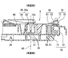
- FIG. 3 is a cross-sectional view taken along line III-III of FIG. It is the IV-IV sectional view taken on the line of FIG.
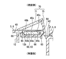
- It is the enlarged view which expanded FIG. 4 partially, and is a figure for demonstrating illumination light.
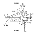
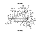
- It is the enlarged view which expanded FIG. 4 partially, and is a figure for demonstrating the engagement state of a 1st ring and a 2nd ring.
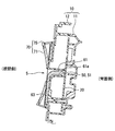
- FIG. 9 is a cross-sectional view taken along line IX-IX in FIG.
- FIG. 9 is a cross-sectional view taken along line XX in FIG.
- a display apparatus 100 for a vehicle is mounted on a vehicle and installed on an instrument panel facing a seat on which an occupant who visually recognizes the display 100 for a vehicle sits.
- the display apparatus 100 for vehicles can display information toward the visual recognition side where a passenger is located.
- the information to be displayed includes, for example, the speed of the vehicle, the number of engine revolutions, the amount of remaining fuel, the temperature of the engine coolant, the current value of the electric motor, and other vehicle conditions such as abnormality of the vehicle.
- Other information to be displayed includes, for example, various information such as an alarm, road information, visibility auxiliary information, and electronic mail.
- such a vehicle display device 100 is configured by the main body display unit 5, the ring member 70, and the like.
- the main body display unit 5 includes a case unit 10, a mounting substrate 20, a plurality of display plates 40 and 42, a pointer unit 30, a ring light source unit 50, a light guide prism member 60, and the like.
- the case unit 10 is formed by combining the back side case 11 and the viewing side case 12.
- the back side case 11 is formed of, for example, a synthetic resin in a light shielding property, and covers the mounting substrate 20 from the back side opposite to the viewing side.
- the viewing side case 12 is formed of, for example, a synthetic resin in a light shielding property, covers the mounting substrate 20 from the viewing side, and has a pointer shaft insertion cylindrical portion 12a, a reflecting wall portion 12b, and the like.
- the mounting substrate 20 is formed of, for example, a synthetic resin in a flat plate shape, and is sandwiched between the back side case 11 and the viewing side case 12.
- a light emitting element 35 for illuminating the ring member 70, a stepping motor 31 for rotating the pointer 32a, and the like are mounted and held.
- the plurality of display plates 40 and 42 are plate-like members generally called as dial plates, and cover the openings provided in the plurality of the viewing side case 12 from the viewing side, and are held by the viewing side case 12 ing.
- Each of the display panels 40 and 42 is formed, for example, by partially applying semi-translucent or opaque printing on the surface of a base made of a translucent synthetic resin. In place of printing, painting may be applied.
- the display plate 40 provided corresponding to the inner display portion 6 that performs display in the radial direction inner side than the ring member 70 in the main body display portion 5;
- Two display plates 40 and 42 are adopted, together with a display plate 42 provided corresponding to the outer display portion 8 for displaying on the radially outer side.
- the display plate 42 has a disk shape centered on a central axis AX described later.
- the display plate 42 has an opening formed by circularly penetrating a portion corresponding to the display plate 40, and has a plate-like shape having an outer peripheral contour aligned with the outer peripheral portion of the vehicle display device 100.
- a step is formed between the inner display portion 6 and the outer display portion 8.
- the display plate 42 disposed in the outer display portion 8 is disposed on the back side with respect to the display plate 40 disposed in the inner display portion 6.
- a warning display by an indicator light or a display indicating an operating state of a direction indicator or the like is performed.
- the inner display unit 6 for example, information is displayed by the pointer unit 30.
- the pointer unit 30 has a plurality of stepping motors 31 and a plurality of pointers 32a and 32b.
- the stepping motor 31 is provided corresponding to each of the hands 32 a and 32 b individually, and is held on the back side of the mounting substrate 20.
- the pointers 32a and 32b integrally have a connecting portion 33 and a needle-like portion 34.
- the connecting portion 33 is connected to the rotation shaft of the stepping motor 31 in the pointer shaft insertion cylindrical portion 12 a formed in a hollow cylindrical shape in the viewing side case 12 on the rear side of the display plate 40.
- the needle portion 34 is formed in a needle shape on the viewing side of the display plate 40 and is connected to the connection portion 33 through the through hole of the display plate 40.
- the hands 32a and 32b rotate around the rotation axis according to the output of the stepping motor 31, and can display information according to the rotation position (the indicated position of the scale). It has become.
- the pointer unit 30 is provided with two pointers 32a and 32b, among which the pointer 32a indicating the speed of the vehicle is the main pointer, and the pointer 32b indicating the remaining amount of fuel is the sub-guide. ing.
- the rotation center of the main pointer 32a is taken as the central axis AX.
- the central axis AX is common to the center of the ring member 70, and in the present embodiment, the words “radially inner side”, “radially outer side”, “circumferential direction” and “axial direction” mean the central axis AX hereinafter. It is defined on the basis of
- the rear end of the pointer shaft insertion cylinder 12a is disposed with a small gap from the mounting substrate 20, and in the mounting substrate 20, the light emitting element 35 is disposed at a location surrounded by the pointer shaft insertion cylinder 12a. It is done. When the light emitting element 35 emits light, the needle-like portion 34 is illuminated and emits light.
- the ring light source unit 50 is configured of a plurality of light emitting elements 51 disposed on the viewing side of the mounting substrate 20.
- a light emitting diode element is adopted as the light emitting element 51 of the present embodiment, and each light emitting element 51 is connected to a power source through a wiring pattern on the mounting substrate 20, thereby introducing the introduction portion 61 of the light guiding prism member 60. It is designed to emit illumination light.
- Each light emitting element 51 may be a light emitting element that emits single color light, or may be a multi-color light emitting element that can switch colors.
- the light guide prism member 60 is formed of, for example, an acrylic resin or a synthetic resin such as polycarbonate resin so as to have a high light transmittance, and between the mounting substrate 20 and the display plate 40, that is, from the ring member 70. Also on the back side. As shown in FIG. 5, the light guiding prism member 60 is housed in a housing space surrounded by the reflecting wall portion 12 b of the viewing side case 12. Then, the light guide prism member 60 integrally forms the lead-in portion 61 and the lead-out portion 63.
- the lead-in portion 61 is provided so as to extend from the incident end 61 a facing the ring light source portion 50 toward the lead-out portion 63 on the viewing side and radially outside. There is no optical interface at the connection between the lead-in portion 61 and the lead-out portion 63, and the lead-in portion 61 and the lead-out portion 63 are continuously formed.
- Illumination light from the light emitting element 51 of the ring light source unit 50 is introduced into the medium of the introducing unit 61 from the incident end 61 a.
- the illumination light introduced into the inside is guided by the inside of the introduction part 61 to the lead-out part 63 while being reflected by the surface of the introduction part 61.
- the illumination light that has been emitted into the accommodation space halfway is also returned to the inside of the light guide prism member 60 by being reflected by the specular reflection wall portion 12b.
- the lead-out portion 63 is disposed to face the ring member 70 with the display plate 40 interposed therebetween.
- the lead-out portion 63 has an annular plate shape centered on the central axis AX.
- an edge portion 65 is formed on the radially inner side and the radially outer side with the lead-out surface 64 interposed therebetween.
- the lead-out surface 64 pinched by the edge portion 65 from both sides in the radial direction is an annular shape having a width in the radial direction.
- a reflective surface 66 is provided in a planar shape.
- the illumination light guided from the introduction unit 61 to the lead-out unit 63 is reflected by the edge portion 65 and the reflection surface 66 inside the medium of the lead-out unit 63, and is circumferentially compared with that in the circumferential direction. Distributed at a uniform density.
- Such illumination light is emitted from the lead-out surface 64 to the display plate 40 and emitted to the outside of the lead-out portion 63.
- the illumination light can be emitted relatively uniformly from the central portion 64a of the lead-out surface 64, but the edge 65 is obtained at the inner circumferential portion 64b and the outer circumferential portion 64c located near the edge 65 of the lead-out surface 64. May be uneven in the illumination light under the influence of diffuse reflection and the like.
- the illumination light emitted from the lead-out surface 64 enters the display plate 40.
- the illumination area 40 a and the restriction areas 40 b and 40 c are provided in the facing portion of the display plate facing the lead-out portion 63.
- the illumination area 40 a is provided in an annular shape at a position of the lead-out surface 64 that directly faces the central portion.
- the printing light and the like are not provided on the surface of the display plate 40, that is, the substrate is exposed on the viewing side and the back side, so that the illumination light is transmitted and emitted to the viewing side. It is supposed to be.
- the restricted areas 40b and 40c are provided adjacent to the illumination area 40a.
- the restriction area 40 b is provided continuously in the radial direction inner side than the portion of the lead-out surface 64 that faces the inner circumferential portion 64 b and the portion.
- the restriction area 40 c is provided continuously in the radial direction outside of a portion of the lead-out surface 64 that directly faces the outer peripheral portion 64 c and the portion.
- the light shielding printing or the like is provided on the surface of the display plate 40, whereby the transmission of the illumination light is regulated.
- the black light shielding layer is formed on the surface of the display panel 40 in the restriction region 40c, so that the illumination light is almost shielded and absorbed.
- the central portion 64a of the lead-out surface 64 is roughened by embossing or the like, while the inner peripheral portion 64b and the outer peripheral portion 64c are mirror surfaces. It has become a state.
- the illumination light reflected inside the medium of the lead-out portion 63 those reaching the inner circumferential portion 64b and the outer circumferential portion 64c are likely to be reflected again inside the medium, and reach the central portion 64a.
- the part is easily ejected and diffused to the display plate 40 side. Therefore, it is possible to intensively emit illumination light with less illumination unevenness from the central portion 64 a of the lead-out surface 64. For this reason, the illumination area 40a directly facing the central portion 64a can efficiently emit the illumination light with less illumination unevenness to the viewing side.
- the ring member 70 is attached to the main body display unit 5 and disposed on the viewing side with respect to each of the display plates 40 and 42, so that the ring member 70 protrudes from the main body display unit 5 to the viewing side It looks like it's Below, let the visual recognition side in the ring member 70 be a front end side, and let the back side in the ring member 70 be a rear end side. More specifically, the ring member 70 is disposed to face the light guide prism member 60 while sandwiching the illumination region 40 a of the display plate 40.
- the ring member 70 has a first ring 71 and a second ring 75, and by combining the first ring 71 and the second ring 75, an annular (ring shape) centering on the central axis AX as a whole It is
- the first ring 71 is formed in an annular shape (ring shape) smaller in diameter than the second ring 75 by, for example, a translucent resin of acrylic resin or polycarbonate resin colored in smoke tone. It is done. More specifically, the first ring 71 is formed in a plate shape which is inclined toward the front end side as it goes from the radially inner side to the radially outer side, and thus has a shape like a side surface of a truncated cone as a whole. ing. The first ring 71 is elastic due to the above-described synthetic resin material and shape.
- a radially inward end portion 72 of the first ring 71 is provided with a flat inner contact surface 72a which can be in plane contact with the display plate 42 of the main display unit 5 over the entire circumference. ing.
- the radially outer end portion 73 of the first ring 71 is provided with a flat outer contact surface 73a that can be in plane contact with a second ring 75 described later. Furthermore, the first ring 71 has a plurality of outer protrusions 73 b protruding outward in the radial direction from the outer contact surface 73 a. The plurality of outer protrusions 73 b are arranged at substantially equal intervals in the circumferential direction. In particular, in the present embodiment, by providing the outer projections 73b at four locations, a total of two pairs of outer projections 73b disposed on opposite sides of the central axis AX are present. Further, on the radially outer side of the first ring 71, the space SP is provided between the display panel 40 of the inner display portion 6 and the above-described inclined shape.
- the second ring 75 is formed, for example, of a light shielding synthetic resin in an annular shape (ring shape) larger in diameter than the first ring 71.
- the second ring 75 is disposed radially outward of the first ring 71, and configures the outer peripheral wall 76 of the ring member 70 over the entire circumference.
- the second ring 75 is formed in a plate shape which is inclined toward the front end side from the radially outer side toward the radially inner side, so that the second ring 75 has a shape like a side surface of a truncated cone as a whole. It is presenting.
- the angle of the second ring 75 with respect to the display plate 42 is set larger than the angle of the first ring 71 with respect to the display plate 42.
- the second ring 75 has a full circumferential claw portion 77 on the front end side.
- the entire circumferential claw portion 77 protrudes radially inward from the outer circumferential wall 76 along the entire circumference, and is formed into a flat surface facing the rear end side so as to face the outer contact surface 73a of the first ring 71 It has a face 77a.
- the second ring 75 has a plurality of projecting portions 78 formed so as to project radially inward from the outer peripheral wall 76 on the opposite side of the circumferential protrusion 77 with the outer protrusion 73 b of the radial outer end 73.
- the outer protrusion 73 b of the radially outer end portion 73 is located between the circumferential claw portion 77 and the plurality of projecting portions 78.
- the plurality of projecting portions 78 are arranged at substantially equal intervals in the circumferential direction as many as the outer protrusions 73 b.
- the protruding portions 78 by providing the protruding portions 78 at four locations, there are a total of two pairs of protruding portions 78 disposed on opposite sides of the central axis AX. Further, in the present embodiment, as shown in FIG. 7, an encircling portion 78a surrounding the outer protrusion 73b at intervals from both sides in the circumferential direction is integrally connected to both end portions in the circumferential direction of the projecting portion 78. .
- the outer peripheral wall 76 of the second ring 75 extends over the entire circumference to the display plate 42 disposed in the outer display portion 8.
- the rearmost end 79 of the outer circumferential wall 76 of the second ring 75 located closest to the rear end abuts on the display plate 42.
- the viewing side case 12 is exposed radially outward without being covered by the display plates 40 and 42.
- the exposed portion 6a is formed.
- the exposed portion 6 a forms a circumferential edge portion of the inner display portion 6 in the main body display portion 5.
- main body protrusions 7 protruding outward in the radial direction are provided at locations (four locations in the present embodiment) that substantially coincide with the outer protrusions 73b and the protrusions 78 in the axial direction.
- a recess 7 a that is recessed radially inward is provided.
- a main body contact surface 7b facing the back surface side (rear end side) is formed.
- partial claws protruding inward in the radial direction at positions (four positions in the present embodiment) that substantially coincide with the outer protrusions 73b and the protrusions 78 in the axial direction.
- the parts 80 are provided respectively. That is, the plurality of partial claws 80 are provided at mutually different positions in the circumferential direction.
- Each partial hook 80 is inserted into the corresponding recess 7a, so that the front surface of the partial hook 80 faces the front end, and the contact surface 80b facing the main contact surface 7b is in contact with the main contact surface 7b. It comes to touch.
- positioning portions 7c sandwiching a rib 81 protruding inward in the circumferential direction from the outer peripheral wall 76 from both sides in the circumferential direction are provided at positions shifted in the circumferential direction with respect to the main body protrusion 7.
- the rear end side of the outer peripheral wall 76 is locked to the main display unit 5
- the main body display unit 5 is attached. That is, the claw abutting surface 77 a of the entire peripheral claw 77 of the second ring 75 abuts on the outer contact surface 73 a of the first ring 71, whereby the peripheral claw 77 is the radially outer end of the first ring 71.
- the entire circumference of the portion 73 is pressed from the front end side.
- the contact surface 80b of the partial hook portion 80 of the second ring 75 abuts on the main body contact surface 7b of the main body display portion 5 so that the partial hook portion 80 corresponds to the inner display portion 6 of the main body display portion 5.
- the edge is partially pressed from the rear end side in the circumferential direction.
- the first ring 71 abuts the display plate 40 of the inner display unit 6 at the inner side in the radial direction and at the same time It will be pressed down from the front end side by the all around claw part 77.
- the first ring 71 is elastically deformed to the space SP side by its elasticity, and exerts an elastic reaction force to the front end side on the second ring 75 through the outer contact surface 73 a and the claw contact surface 77 a. That is, the space SP functions as an allowance portion that permits elastic deformation of the first ring 71.
- the display plate 42 constitutes a ring receiving portion for supporting the rear end side of the ring member 70.
- a method of attaching the ring member 70 to the main body display unit 5 will be briefly described.
- the outer protrusion 73b of the first ring 71 is fitted between the entire circumferential claw portion 77 of the second ring 75 and the projection 78.
- the outer projections 73b are restricted in axial movement by the circumferential claws 77 and the projections 78, and are restricted in circumferential movement by the surrounding portions 78a.
- the first ring 71 and the second ring 75 are temporarily fixed.
- the ring member 70 in such a temporarily fixed state is attached to the inner display portion 6.
- the inner abutment surface 72a of the first ring 71 abuts on the display plate 40 of the inner display portion 6 (more specifically, press-contact), and the first ring 71 receives the force from the display plate 40 side.
- the outer contact surface 73a abuts on the claw contact surface 77a of the entire circumferential claw portion 77, and the first ring 71 and the second ring 75 are engaged.
- the partial hook portion 80 of the second ring 75 is fitted into the recess 7 a of the main display unit 5, and the rear end side of the outer peripheral wall 76 is locked to the main display unit 5.
- the first ring 71 is light transmissive, the illumination light transmitted through the illumination area 40a is transmitted to the viewing side, and it is viewed from the occupant as if the ring member 70 is emitting light. Be done. Therefore, the ring light source unit 50 of the main body display unit 5, the light guide prism member 60, and the illumination area 40a of the display plate 40 function as an illumination unit 68 that illuminates the first ring 71 from the rear end side.
- the rear end side of the outer peripheral wall 76 is locked to the main body display portion 5 in a state where the front end side of the outer peripheral wall 76 is engaged with the radial outer side of the first ring 71 Is attached to the main body display unit 5. Then, in the state where the second ring 75 is attached to the main body display unit 5, the engagement with the second ring 75 is maintained by the elastic reaction force due to the elasticity of the first ring 71. As a result, even if manufacturing errors exist in the component dimensions of the first ring 71, the second ring 75, and the main body display unit 5, the first ring 71 is elastically deformed to absorb the dimensional errors, The elastic reaction force makes the engagement state strong. By the above, it is possible to easily manufacture the ring member 70 which is excellent in fixation to the main body display unit 5.
- the second ring 75 is elastically deformed from the first ring 71 to the front end side by the state in which the first ring 71 is elastically deformed to the space SP side with the main body display unit 5. In the state of receiving the reaction force, the engaged state is maintained. In such a configuration, since the space SP allows elastic deformation of the first ring 71, even if there is a manufacturing error in the component dimensions of the first ring 71, the second ring 75, and the main body display unit 5, The dimensional error is reliably absorbed, and the second ring 75 is more susceptible to the elastic reaction force, whereby the engagement state becomes stronger. By the above, it is possible to easily manufacture the ring member 70 which is excellent in fixation to the main body display unit 5.
- the second ring 75 has the all-circumferential claw portion 77 that holds the entire circumference of the radially outer end portion 73 of the first ring 71 from the front end side.
- the first ring 71 can be elastically deformed relatively uniformly all around with the end on the radially inner side in contact with the main body display 5 in the first ring 71 as a fulcrum Since this can be performed, stable pinching can be realized over the entire circumference.
- the second ring 75 is a projection formed so as to project radially inward from the outer peripheral wall 76 on the opposite side across the radially outer end portion 73 with the entire circumferential claw portion 77 It has a part 78.
- the radial outer end portion 73 of the first ring 71 is placed between the entire circumferential claw portion 77 and the projecting portion 78 prior to attachment of the ring member 70 to the main body display portion 5.
- the edge of the 2nd ring 75 or the main body display 5 is elastic over the entire circumference. Since the ring member 70 can not be attached to the main body display unit 5 without deformation, the attachment is extremely difficult.
- the second ring 75 has a plurality of partial claws 80 at different positions in the circumferential direction, which partially press the edge of the main body display 5 from the rear end side. Therefore, since it becomes possible to attach the ring member 70 if only the location where the partial claws 80 are disposed can be attached, the manufacture becomes easier.
- the rearmost end 79 located on the most rear end side in the outer peripheral wall 76 is in contact with the display plate 42 in a state where the display plate 42 as the ring receiving portion is elastically deformed. There is. That is, even if there is a manufacturing error in the dimension of the second ring 75, particularly the outer peripheral wall 76, the display plate 42 can absorb the dimension error, so the first ring 71, the second ring 75, and the main body The engagement and locking positions of the display unit 5 can be adjusted to appropriate positions.
- the first ring 71 has a light transmitting property to transmit the light from the illumination unit 68.
- the light emission of the first ring 71 due to the illumination can be reliably realized by the ring member 70 that is well fixed to the main body display unit 5.
- the first ring 71 extends from the outer contact surface 73a to the rear end side substantially parallel to the outer peripheral wall 76 of the second ring 75. It may have an inner wall 71d formed. It is preferable that a gap GP be formed between the rear end side of the inner wall 71 d and the display plate 40 without contacting the display plate 40. This gap corresponds to the space of the above-described embodiment.
- the outer protrusion 73 b protrudes radially outward from the relatively rear end side of the inner wall 71 d.
- the protruding portion 78 of the second ring 75 is formed so as to protrude radially inward from the outer peripheral wall 76 on the opposite side across the outer protrusion 73 b with the entire circumferential claw portion 77 as in the embodiment described above. ing.
- the first ring 71 is a two-color molded component in which the light diffusion portion 71a and the smoked portion 71b are integrally formed.
- the light diffusion portion 71a is disposed on the rear end side of the first ring 71, and integrally includes the inclined plate portion 71c and the inner wall 71d, thereby forming an L shape or a V shape in a radial cross section. It is formed.
- the light diffusion portion 71 a is formed of a light diffusion material that diffuses the illumination light.
- the smoked portion 71b covers a portion of the first ring 71 exposed to the front end side, and more specifically covers the surface of the inclined plate portion 71c.
- the smoked portion 71 b is formed of, for example, a semi-transparent synthetic resin of acrylic resin or polycarbonate resin colored in a smoke tone.
- the outer protrusion 73b and the protrusion 78 are disposed on the rear end side relative to the one embodiment described above, so that the partial claw 80 is axially aligned with the outer protrusion 73b and the protrusion 78. It is difficult to arrange in the place where it substantially agrees with. For this reason, the partial claw portion 80 is disposed at a position shifted in the circumferential direction with respect to the outer protrusion 73 b and the protrusion 78 on the rear end side with respect to the outer protrusion 73 b and the protrusion 78.
- the space SP may be filled with a deformable member such as a sponge.
- a deformable member such as a sponge can be made to function as an allowance portion for permitting elastic deformation of the first ring 71.
- the ring member 70 may not be illuminated by the illumination unit 68.
- the first ring 71 may be formed to have a light shielding property.
- the main body display unit 5 displays an image by means of a liquid crystal panel or an organic EL display, etc., instead of the display by the pointer unit 30 or in the inner display unit 6, for example. It may be
Landscapes
- Engineering & Computer Science (AREA)
- Physics & Mathematics (AREA)
- General Physics & Mathematics (AREA)
- Chemical & Material Sciences (AREA)
- Combustion & Propulsion (AREA)
- Transportation (AREA)
- Mechanical Engineering (AREA)
- Instrument Panels (AREA)
- Details Of Measuring Devices (AREA)
Abstract
情報を表示する本体表示部(5)と、本体表示部に取付けられるリング状のリング部材(70)と、を有する車両用表示装置であって、当該車両用表示装置は第1リング(71)と第2リング(75)を備える。第1リングは、弾性を有しリング状に形成されている。第2リングは、第1リングの径方向外側に配置されてリング部材の外周壁(76)を構成するリング状に形成されている。第1リングと第2リングは、リング部材を構成している。第2リングは、外周壁の前端側が第1リングの径方向外側に係合された状態で外周壁の後端側が本体表示部に係止されることにより、本体表示部に取付けられている。第2リングが本体表示部に取付けられた状態において、第1リングの弾性による弾性反力によって、第1リングと第2リングとの係合状態が維持されている。
Description
本出願は、当該開示内容が参照によって本出願に組み込まれた、2017年8月4日に出願された日本特許出願2017-151652号を基にしている。
本開示は、車両に搭載される車両用表示装置に関する。
従来、車両に搭載される車両用表示装置が知られている。特許文献1に開示の装置は、情報を表示する本体表示部と、本体表示部の径方向外側に取付けられるリング状のリング部材と、を備えている。リング部材は、リング状に形成された第1リングと、当該第1リングの径方向外側に配置されてリング部材の外周壁を構成する第2リングと、を有している。
ここで、第2リングの後端側は、第1リングにより本体表示部と共に隙間なく挟み込まれている。
しかしながら、特許文献1の装置のように、複数の部品を、第1リングによりまとめて挟み込む構成では、複数の部品寸法の製造誤差が累積的に積み上がり、全ての部材が第1リングの挟み込み部分に入りきらずに組み付けが困難になることや、逆に隙間が発生して車両振動等によるリング部材のがたつきが懸念され得る。このため、本体表示部に対する固定が良好なリング部材を、製造容易に実現することが難しかった。
本開示は、本体表示部に対する固定が良好なリング部材を、製造容易に実現した車両用表示装置を提供することを目的とする。
本開示の第1形態によれば、情報を表示する本体表示部と、本体表示部に取付けられるリング状のリング部材と、を有する車両用表示装置は、第1リングと第2リングを備える。第1リングは、弾性を有しリング状に形成されている。第2リングは、第1リングの径方向外側に配置されてリング部材の外周壁を構成するリング状に形成されている。第1リングと第2リングは、リング部材を構成している。第2リングは、外周壁の前端側が第1リングの径方向外側に係合された状態で外周壁の後端側が本体表示部に係止されることにより、本体表示部に取付けられている。第2リングが本体表示部に取付けられた状態において、第1リングの弾性による弾性反力によって、第1リングと第2リングとの係合状態が維持されている。
このような車両用表示装置によると、第2リングは、外周壁の前端側が第1リングの径方向外側に係合された状態で外周壁の後端側が本体表示部に係止されることにより、本体表示部に取付けられている。そして、第2リングが本体表示部に取付けられた状態において、第1リングの弾性による弾性反力によって第2リングとの係合状態が維持されている。この結果、第1リング、第2リング及び本体表示部の部品寸法に製造誤差が存在していたとしても、第1リングが弾性変形することにより当該寸法の誤差が吸収されると共に、弾性反力により係合状態が強固なものとなる。以上により、本体表示部に対する固定が良好なリング部材を、製造容易に実現することができる。
本開示についての上記目的およびその他の目的、特徴や利点は、添付の図面を参照しながら下記の詳細な記述により、より明確になる。
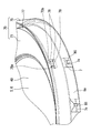
一実施形態における車両用表示装置を部分的に示す正面図である。
図1のII-II線断面図である。
図1のIII-III線断面図である。
図1のIV-IV線断面図である。
図4を部分的に拡大した拡大図であって、照明光について説明するための図である。
図4を部分的に拡大した拡大図であって、第1リングと第2リングとの係合状態について説明するための図である。
一実施形態における外周突起等を示す斜視図であって、第2リングを透過させて示す透過斜視図である。
第1変形例における図1に対応する図である。
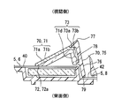
図8のIX-IX線断面図である。
図8のX-X線断面図である。
一実施形態を図面に基づいて説明する。
図1に示すように、本開示の一実施形態による車両用表示装置100は、車両に搭載され、車両用表示装置100を視認する乗員が着座する座席と対向するインストルメントパネルに設置されている。車両用表示装置100は、乗員が位置することとなる視認側へ向けて情報を表示可能となっている。表示される情報としては、例えば車両の速度、エンジン回転数、燃料残量、エンジン冷却水の水温、電動モータの電流値、その他車両の異常等の車両の状態が挙げられる。その他表示される情報としては、例えば警報、道路情報、視界補助情報、電子メール等の各種情報が挙げられる。
このような車両用表示装置100は、図2~4にも示すように、本体表示部5及びリング部材70等により構成されている。本体表示部5は、ケース部10、実装基板20、複数の表示板40,42、指針部30、リング用光源部50、及び導光プリズム部材60等により構成されている。
ケース部10は、背面側ケース11及び視認側ケース12を組み合わせて形成されている。背面側ケース11は、例えば合成樹脂により遮光性に形成されており、実装基板20を視認側とは反対側の背面側から覆っている。視認側ケース12は、例えば合成樹脂により遮光性に形成されており、実装基板20を視認側から覆うと共に、指針軸挿通筒部12a及び反射壁部12b等を有している。
実装基板20は、例えば合成樹脂により平板状に形成されており、背面側ケース11と視認側ケース12との間に挟まれている。実装基板20には、リング部材70を照明するための発光素子35、指針32aを回動させるためのステッピングモータ31等が実装及び保持されている。
複数の表示板40,42は、一般的に文字板とも呼ばれている板状部材であり、視認側ケース12に複数設けられた開口部を視認側から覆い、当該視認側ケース12によって保持されている。各表示板40,42は、例えば透光性を有する合成樹脂からなる基材の表面に、半透光性又は遮光性の印刷が部分的に施されて形成されている。なお、印刷に代えて、塗装が施されていてもよい。
本実施形態における複数の表示板40,42として、本体表示部5のうちリング部材70より径方向内側において表示を行なう内側表示部6に対応して設けられた表示板40と、リング部材70より径方向外側において表示を行なう外側表示部8に対応して設けられた表示板42との、2つの表示板40,42が採用されている。表示板42は、後述する中心軸AXを中心とした円板状を呈している。表示板42は、表示板40に対応する箇所を円形に刳り貫いた開口穴を有し、外周輪郭を車両用表示装置100の外周部に合わせて形成された板状を呈している。
ここで、視認側ケース12において、内側表示部6と外側表示部8との間に段差が形成されている。この結果、外側表示部8に配置された表示板42は、内側表示部6に配置された表示板40に対して背面側に配置されている。
外側表示部8では、例えば表示灯による警告表示又は方向指示器の作動状態を示す表示等が実施される。内側表示部6では、例えば指針部30による情報の表示を行なう。
指針部30は、複数のステッピングモータ31及び複数の指針32a,32bを有している。ステッピングモータ31は、各指針32a,32bに個別に対応して設けられ、実装基板20の背面側に保持されている。
指針32a,32bは、連結部33及び針状部34を一体的に有している。連結部33は、表示板40よりも背面側の視認側ケース12において中空筒状に形成された指針軸挿通筒部12a内において、ステッピングモータ31の回転軸と連結されている。針状部34は、表示板40よりも視認側において針状に形成されていると共に、表示板40の貫通穴を通して連結部33と連結されている。指針32a,32bは、ステッピングモータ31の出力に応じてその回転軸を回転中心として回動するようになっており、回動位置(目盛の指示位置)に応じて情報を表示することが可能となっている。
本実施形態では、指針部30に2つの指針32a,32bが設けられており、このうち車両の速度を示す指針32aが主指針となっており、燃料残量を示す指針32bがサブ指針となっている。本実施形態では、主の指針32aの回転中心を中心軸AXとする。この中心軸AXは、リング部材70の中心と共通となっており、以後、本実施形態において、「径方向内側」「径方向外側」「周方向」「軸方向」の語は、中心軸AXを基準に規定される。
なお、指針軸挿通筒部12aの背面側端部は、実装基板20と隙間少なく配置されており、実装基板20において、指針軸挿通筒部12aに囲まれた箇所には、発光素子35が配置されている。発光素子35が発光することで、針状部34が照明されて発光するようになっている。
リング用光源部50は、実装基板20の視認側に配置された複数の発光素子51により構成されている。本実施形態の発光素子51には、発光ダイオード素子が採用されており、各発光素子51は、実装基板20上の配線パターンを通じて電源と接続されることで、導光プリズム部材60の導入部61へ向けて照明光を発するようになっている。なお、各発光素子51は、単色に発光する発光素子であってもよく、色の切り替えが可能なマルチカラーの発光素子であってもよい。
導光プリズム部材60は、例えばアクリル樹脂ないしはポリカーボネイト樹脂等の合成樹脂により、透過率の高い透光性に形成されており、実装基板20と表示板40との間に、すなわち、リング部材70よりも背面側に配置されている。図5に示すように導光プリズム部材60は、視認側ケース12の反射壁部12bに囲まれた収容空間に、収容されている。そして、導光プリズム部材60は、導入部61及び導出部63を一体的に形成している。
導入部61は、リング用光源部50と対向する入射端61aから、視認側かつ径方向外側の導出部63へ向かって延伸して設けられている。導入部61と導出部63との接続箇所には、光学的な界面はなく、導入部61と導出部63とが連続的に形成されている。
リング用光源部50の発光素子51からの照明光は、入射端61aから導入部61の媒質内部に導入される。内部に導入された照明光は、導入部61の表面にて反射されながら、導入部61の内部を導出部63まで導光されるようになっている。また、途中で収容空間に射出されてしまった照明光も、鏡面状の反射壁部12bに反射されることで、再び導光プリズム部材60の内部に戻される。
導出部63は、表示板40を間に挟みつつ、リング部材70と対向して配置されている。導出部63は、中心軸AXを中心とする円環板状を呈している。導出部63において、導出面64を挟んで径方向内側及び径方向外側には、エッジ部65が形成されている。こうした構成により、エッジ部65に径方向両側から挟まれた導出面64は、当該径方向に幅をもった円環状となっている。導出部63において、導出面64の反対側には、反射面66が平面状に設けられている。
導入部61から導出部63へと導光された照明光は、導出部63の媒質内部にて、エッジ部65及び反射面66に反射されながら、周方向に旋回することにより、周方向に比較的均質な密度に分布する。こうした照明光が導出面64から表示板40へ向けて、導出部63の外部へ射出される。この際、導出面64の中央部64aからは、照明光を比較的均質に射出可能であるが、導出面64のエッジ部65近傍に位置する内周部64b及び外周部64cでは、エッジ部65での乱反射等の影響を受け、照明光にムラが生じ得る。
導出面64から射出された照明光は、表示板40に入射することとなる。ここで、表示板において導出部63と対向する対向部には、照明領域40a及び規制領域40b,40cが設けられている。
照明領域40aは、導出面64のうち中央部と正対する箇所に円環状に設けられている。照明領域40aでは、表示板40の表面に印刷等が設けられていない、すなわち基材が視認側にも背面側にも露出していることにより、照明光を透過して、視認側へ射出するようになっている。
規制領域40b,40cは、照明領域40aと隣接して設けられている。具体的に、規制領域40bは、導出面64のうち内周部64bと正対する箇所、及び当該箇所よりもさらに径方向内側に連続して設けられている。規制領域40cは、導出面64のうち外周部64cと正対する箇所、及び当該箇所よりさらに径方向外側に連続して設けられている。規制領域40cでは、表示板40の表面に遮光性の印刷等が設けられていることにより、照明光の透過が規制されている。特に本実施形態では、規制領域40cにおいて、表示板40の表面に黒色の遮光層が形成されていることで、照明光は殆ど遮光吸収されるようになっている。
こうした照明領域40a及び規制領域40b,40cの配置に応じて、導出面64のうち中央部64aは、シボ加工等により粗面状となっている一方、内周部64b及び外周部64cは、鏡面状となっている。このようにすることで、導出部63の媒質内部を反射される照明光のうち、内周部64b及び外周部64cに到達するものは再び媒質内部に反射され易く、中央部64aに到達する一部は表示板40側に射出及び拡散され易くなる。したがって、照明ムラの少ない照明光を導出面64の中央部64aから集中的に射出することが可能となる。このため、当該中央部64aと正対する照明領域40aは、照明ムラの少ない照明光を効率的に視認側に射出することができる。
リング部材70は、図1~4に示すように、本体表示部5に取付けられ、表示板40,42それぞれに対して視認側に配置されていることで、本体表示部5から視認側に突出しているように視認される。以下では、リング部材70において視認側を、前端側とし、リング部材70において背面側を、後端側とする。より詳細に、リング部材70は、表示板40の照明領域40aを間に挟みつつ、導光プリズム部材60と対向して配置されている。リング部材70は、第1リング71と第2リング75とを有し、第1リング71と第2リング75が組み合わさることにより、全体としては中心軸AXを中心とした円環状(リング状)を呈している。
図6に示すように、第1リング71は、例えばスモーク調に着色されたアクリル樹脂ないしはポリカーボネイト樹脂の半透光性の合成樹脂により、第2リング75より小径の円環状(リング状)に形成されている。より詳細に第1リング71は、径方向内側から径方向外側へ向かう程前端側へ向かうように傾斜する板状に形成されていることで、全体としては円錐台の側面のような形状を呈している。第1リング71は、上述の合成樹脂材料及び形状により、弾性を有している。
第1リング71において径方向内側の端部72には、本体表示部5の表示板42と面状に当接可能な平面状に形成された内側当接面72aが全周に亘って設けられている。
第1リング71において径方向外側端部73には、後述する第2リング75と面状に当接可能な平面状に形成された外側当接面73aが全周に亘って設けられている。さらに、第1リング71は、外側当接面73aから径方向外側に突出した外側突起73bを、複数有している。複数の外側突起73bは、周方向に略等間隔に配置されている。特に本実施形態では外側突起73bが4箇所に設けられることで、中心軸AXを挟んで互いに反対側に配置された一対の外側突起73bが、合計二対存在している。また、第1リング71の径方向外側においては、上述の傾斜形状により内側表示部6の表示板40との間に空間SPが設けられている。
第2リング75は、例えば遮光性の合成樹脂により、第1リング71より大径の円環状(リング状)に形成されている。第2リング75は、第1リング71の径方向外側に配置され、リング部材70の外周壁76を全周に亘って構成している。より詳細に、第2リング75は、径方向外側から径方向内側へ向かう程前端側へ向かうように傾斜する板状に形成されていることで、全体としては円錐台の側面のような形状を呈している。ここで、第2リング75の表示板42に対する角度は、第1リング71の表示板42に対する角度よりも大きく設定されている。
第2リング75は、その前端側に、全周爪部77を有している。全周爪部77は、全周において外周壁76から径方向内側に突出し、第1リング71の外側当接面73aと対向するように、後端側を向く平面状に形成された爪当接面77aを有している。
また、第2リング75は、全周爪部77とは径方向外側端部73の外側突起73bを挟んだ反対側において、外周壁76から径方向内側に突出して形成された突出部78を複数有している。つまり、径方向外側端部73の外側突起73bは、全周爪部77と複数の突出部78との間に位置している。複数の突出部78は、外側突起73bと同数、周方向に略等間隔に配置されている。特に本実施形態では突出部78が4箇所に設けられることで、中心軸AXを挟んで互いに反対側に配置された一対の突出部78が、合計二対存在している。また本実施形態では、図7に示すように、外側突起73bを周方向両側から間隔を空けて囲む囲み部78aが、突出部78の周方向両端部と接続して一体的に設けられている。
さらに第2リング75の外周壁76は、図6に示すように、全周に亘って、外側表示部8に配置された表示板42まで延伸している。第2リング75の外周壁76において最も後端側に位置する最後端部79は、表示板42と当接するようになっている。
図6,7に示すように、内側表示部6と外側表示部8との間に形成された段差部分では、視認側ケース12が表示板40,42に覆われずに径方向外側に剥き出し状態となっている剥き出し部6aが形成されている。この剥き出し部6aは、本体表示部5において内側表示部6の円周状の縁部を形成している。
剥き出し部6aにおいて、外側突起73b及び突出部78と軸方向に略一致する箇所(本実施形態では4箇所)には、径方向外側に突出する本体突起7がそれぞれ設けられている。各本体突起7の中央には、径方向内側に凹む凹部7aが設けられている。凹部7aの内部には、背面側(後端側)を向く本体当接面7bが形成されている。
凹部7aに対応して、第2リング75の後端側において外側突起73b及び突出部78と軸方向に略一致する箇所(本実施形態では4箇所)には、径方向内側に突出する部分爪部80がそれぞれ設けられている。すなわち、複数の部分爪部80が互いに周方向の異なる位置に設けられている。各部分爪部80が対応する凹部7aに挿入されていることで、部分爪部80において前端側を向き、本体当接面7bと対向する爪当接面80bが当該本体当接面7bと当接するようになっている。
また、剥き出し部6aにおいて、本体突起7に対して周方向にずれた箇所には、外周壁76から周方向内側に突出するリブ81を周方向の両側から挟む位置決め部7cが設けられている。
こうして第2リング75は、その外周壁76の前端側が第1リング71の径方向外側端部73に係合された状態で、外周壁76の後端側が本体表示部5に係止されることにより、当該本体表示部5に取付けられていることとなる。すなわち、第2リング75の全周爪部77の爪当接面77aが第1リング71の外側当接面73aと当接することで、全周爪部77が第1リング71の径方向外側端部73の全周を前端側から押さえ付けている。これと共に、第2リング75の部分爪部80の爪当接面80bが本体表示部5の本体当接面7bと当接することで、部分爪部80が本体表示部5における内側表示部6の縁部を周方向において部分的に後端側から押さえ付けている。
こうして第2リング75が本体表示部5に取付けられた状態において、第1リング71は、径方向内側において内側表示部6の表示板40と当接すると同時に、径方向内側において第2リング75の全周爪部77により前端側から押さえ付けられていることとなる。このとき、第1リング71は、その弾性により空間SP側に弾性変形した状態となり、外側当接面73a及び爪当接面77aを通じて、前端側への弾性反力を第2リング75に及ぼす。すなわち、空間SPは、第1リング71の弾性変形を許容する許容部として機能している。空間SPを利用して第1リング71が及ぼす弾性反力によって、第2リング75の全周爪部77における第1リング71との係合及び部分爪部80における本体表示部5との係合が強固なものとなり、第1リング71と第2リング75との係合状態が維持される。
また、第2リング75の最後端部79が表示板42と当接する際に、表示板42が弾性変形することにより、第2リング75の寸法における製造誤差を吸収しつつ、上述の係合状態を維持することが可能となっている。こうして、表示板42がリング部材70の後端側を受け支えるリング受け部を構成している。
こうしたリング部材70の本体表示部5への取り付け方法について簡潔に説明する。まず、第1リング71を弾性変形させながら、当該第1リング71の外側突起73bを第2リング75の全周爪部77と突出部78との間に嵌め込む。外側突起73bが全周爪部77及び突出部78により軸方向の移動を規制されると共に、囲み部78aにより周方向の移動を規制される。こうして、第1リング71と第2リング75とが仮固定状態となる。
このような仮固定状態のリング部材70を、内側表示部6に取付ける。この際に、第1リング71の内側当接面72aが内側表示部6の表示板40と当接し(より詳細には圧接し)、表示板40側からの力を受けて第1リング71が空間SP側に弾性変形すると共に、外側当接面73aが全周爪部77の爪当接面77aと当接して、第1リング71と第2リング75とが係合される。同時に、第2リング75の部分爪部80が本体表示部5の凹部7aに嵌り込み、外周壁76の後端側が本体表示部5に対して係止される。第1リング71と本体表示部5との間の空間SPを第1リング71の弾性変形に利用しつつ、第1リング71、第2リング75及び本体表示部5の三部品が三つ巴に相互作用し合うことで、リング部材70の強固な固定が実現される。
さらには、第1リング71が光透過性を有することにより、照明領域40aを透過した照明光を視認側に透過するようになっており、乗員からはリング部材70が発光しているように視認される。したがって、本体表示部5のリング用光源部50、導光プリズム部材60、及び表示板40の照明領域40aが、後端側から第1リング71を照明する照明部68として機能している。
(作用効果)
以上説明した本実施形態の作用効果を以下に改めて説明する。
以上説明した本実施形態の作用効果を以下に改めて説明する。
上述した一実施形態によると、第2リング75は、外周壁76の前端側が第1リング71の径方向外側に係合された状態で外周壁76の後端側が本体表示部5に係止されることにより、本体表示部5に取付けられている。そして、第2リング75が本体表示部5に取付けられた状態において、第1リング71の弾性による弾性反力によって第2リング75との係合状態が維持されている。この結果、第1リング71、第2リング75及び本体表示部5の部品寸法に製造誤差が存在していたとしても、第1リング71が弾性変形することにより当該寸法誤差が吸収されると共に、弾性反力により係合状態が強固なものとなる。以上により、本体表示部5に対する固定が良好なリング部材70を、製造容易に実現することができる。
また、上述した一実施形態によると、第2リング75は、第1リング71を本体表示部5との間の空間SP側に弾性変形させた状態によって、第1リング71から前端側への弾性反力を受けた状態で、係合状態を維持している。このような構成では、空間SPが第1リング71の弾性変形を許容するので、第1リング71、第2リング75及び本体表示部5の部品寸法に製造誤差が存在していたとしても、当該寸法の誤差が確実に吸収されると共に、第2リング75が弾性反力を受けやすくなることで、係合状態はより強固なものとなる。以上により、本体表示部5に対する固定が良好なリング部材70を、製造容易に実現することができる。
また、上述した一実施形態によると、第2リング75は、第1リング71の径方向外側端部73の全周を前端側から押さえ付ける全周爪部77を有する。全周爪部77による押さえ付けでは、例えば第1リング71において本体表示部5と当接する径方向内側の端部を支点として、第1リング71を全周に比較的均等に弾性変形させることができるので、全周に亘って安定した挟み込みを実現できる。
また、上述した一実施形態によると、第2リング75は、全周爪部77とは径方向外側端部73を挟んだ反対側において、外周壁76から径方向内側に突出して形成された突出部78を有する。このような突出部78を設けた場合、リング部材70の本体表示部5への取り付け時に、先立って第1リング71の径方向外側端部73を全周爪部77と突出部78との間に挿入することで、第1リング71と第2リング75とを仮固定した状態で、リング部材70を本体表示部5に対して組付けることが可能となる。したがって、製造がより容易なものとなる。
仮に、本体表示部5の縁部を部分的に後端側から押さえ付ける爪部を、全周に設けた場合、第2リング75又は本体表示部5の縁部を、全周に亘って弾性変形させなければ、リング部材70を本体表示部5に取り付けできないため、当該取り付けは困難極まる。しかしながら上述した一実施形態によると、第2リング75は、本体表示部5の縁部を部分的に後端側から押さえ付ける部分爪部80を、周方向の異なる位置に複数有する。したがって、部分爪部80の配置箇所のみ取り付け対応すれば、リング部材70の取り付けが可能となるので、製造がより容易なものとなる。
また、上述した一実施形態によると、外周壁76において最も後端側に位置する最後端部79は、リング受け部としての表示板42を弾性変形させた状態で、表示板42と当接している。すなわち、第2リング75の特に外周壁76の寸法に製造誤差が存在していたとしても、表示板42が当該寸法誤差を吸収することができるので、第1リング71、第2リング75及び本体表示部5の係合及び係止位置を、適切な位置に調整可能となる。
また、上述した一実施形態によると、第1リング71は、照明部68からの光を透過する光透過性を有する。照明による第1リング71の発光を、本体表示部5に対する固定が良好なリング部材70によって、確実に実現することができる。
(他の実施形態)
以上、一実施形態について説明したが、本開示は、当該実施形態に限定して解釈されるものではなく、本開示の要旨を逸脱しない範囲内において種々の実施形態に適用することができる。
以上、一実施形態について説明したが、本開示は、当該実施形態に限定して解釈されるものではなく、本開示の要旨を逸脱しない範囲内において種々の実施形態に適用することができる。
具体的に、第1変形例としては、図8~10に示すように、第1リング71は、外側当接面73aから第2リング75の外周壁76と略平行に後端側に延伸して形成された内部壁71dを有していてもよい。この内部壁71dの後端側は、表示板40と当接せずに、表示板40との間に隙間GPを形成していることが好ましい。この隙間が上述した一実施形態の空間に相当する。ここで、外側突起73bは、内部壁71dの比較的後端側から、径方向外側に突出している。そして、第2リング75の突出部78は、上述した一実施形態と同様に、全周爪部77とは外側突起73bを挟んだ反対側において、外周壁76から径方向内側に突出して形成されている。
なお、図8~10の例において、第1リング71は、光拡散部71aとスモーク部71bとを一体的に形成した二色成形部品となっている。光拡散部71aは、第1リング71において後端側に配置され、傾斜板部71cと内部壁71dとを一体的に有することで、径方向断面においてL字状ないしはV字状をなすように形成されている。光拡散部71aは、照明光を拡散する光拡散材料により形成されている。スモーク部71bは、第1リング71において前端側に露出する部分を覆い、より詳細には傾斜板部71cの表面を覆っている。スモーク部71bは、例えばスモーク調に着色されたアクリル樹脂ないしはポリカーボネイト樹脂の半透光性の合成樹脂により、形成されている。
そして、図8~10の例において外側突起73b及び突出部78が上述した一実施形態よりも後端側に配置されていることにより、部分爪部80を外側突起73b及び突出部78と軸方向に略一致する箇所に配置することは、困難となっている。このため、部分爪部80は、外側突起73b及び突出部78よりも後端側おいて、外側突起73b及び突出部78に対して周方向にずれた箇所に配置されている。
第2変形例としては、空間SPは、スポンジ等の変形可能な部材により満たされていてもよい。この場合であっても、スポンジ等の変形可能な部材を、第1リング71の弾性変形を許容する許容部として機能させることができる。
第3変形例としては、リング部材70は、照明部68により照明されない構成であってもよい。この場合に、第1リング71を遮光性に形成してもよい。
第4変形例としては、本体表示部5は、例えば内側表示部6において、指針部30による表示と共に、又は指針部30による表示に代えて、液晶パネルないしは有機ELディスプレイ等により画像を表示するものであってもよい。
Claims (7)
- 情報を表示する本体表示部(5)と、前記本体表示部に取付けられるリング状のリング部材(70)と、を備えた車両用表示装置であって、
弾性を有しリング状に形成された第1リング(71)と、
前記第1リングの径方向外側に配置されて前記リング部材の外周壁(76)を構成するリング状に形成された第2リング(75)と、を備え、
前記第1リングと前記第2リングは、前記リング部材を構成し、
前記第2リングは、前記外周壁の前端側が前記第1リングの径方向外側に係合された状態で前記外周壁の後端側が前記本体表示部に係止されることにより、前記本体表示部に取付けられており、
前記第2リングが前記本体表示部に取付けられた状態において、前記第1リングの弾性による弾性反力によって、前記第1リングと前記第2リングとの係合状態が維持されている車両用表示装置。 - 前記第1リングは、その径方向内側において前記本体表示部と当接すると共に、その径方向外側において前記本体表示部との間に、空間(SP)を設けてなり、
前記第2リングは、前記第1リングを前記空間側に弾性変形させた状態によって、前記第1リングから前端側への弾性反力を受けた状態で、前記係合状態を維持している請求項1に記載の車両用表示装置。 - 前記第2リングは、前記第1リングの径方向外側端部の全周を前端側から押さえ付ける全周爪部(77)を有する請求項1又は2に記載の車両用表示装置。
- 前記第2リングは、前記全周爪部とは前記径方向外側端部を挟んだ反対側において、前記外周壁から径方向内側に突出して形成された突出部(78)を有する請求項3に記載の車両用表示装置。
- 前記第2リングは、前記本体表示部の縁部を部分的に後端側から押さえ付ける部分爪部(80)を、周方向の異なる位置に複数有する請求項1から4のいずれか1項に記載の車両用表示装置。
- 前記本体表示部は、
前記リング部材の径方向内側にて表示を行なう内側表示部(6)と、
前記内側表示部よりも径方向外側において、前記内側表示部とは段差を形成することにより前記内側表示部よりも後端側に配置され、弾性を有するリング受け部(42)を有し、
前記外周壁において最も後端側に位置する最後端部は、前記リング受け部を弾性変形させた状態で、前記リング受け部と当接している請求項1から5のいずれか1項に記載の車両用表示装置。 - 前記本体表示部は、後端側から前記第1リングを照明する照明部(68)を有し、
前記第1リングは、前記照明部からの光を透過する光透過性を有する請求項1から6のいずれか1項に記載の車両用表示装置。
Applications Claiming Priority (2)
| Application Number | Priority Date | Filing Date | Title |
|---|---|---|---|
| JP2017-151652 | 2017-08-04 | ||
| JP2017151652A JP6669140B2 (ja) | 2017-08-04 | 2017-08-04 | 車両用表示装置 |
Publications (1)
| Publication Number | Publication Date |
|---|---|
| WO2019026544A1 true WO2019026544A1 (ja) | 2019-02-07 |
Family
ID=65232794
Family Applications (1)
| Application Number | Title | Priority Date | Filing Date |
|---|---|---|---|
| PCT/JP2018/025691 Ceased WO2019026544A1 (ja) | 2017-08-04 | 2018-07-06 | 車両用表示装置 |
Country Status (2)
| Country | Link |
|---|---|
| JP (1) | JP6669140B2 (ja) |
| WO (1) | WO2019026544A1 (ja) |
Cited By (1)
| Publication number | Priority date | Publication date | Assignee | Title |
|---|---|---|---|---|
| WO2020235682A1 (ja) * | 2019-05-23 | 2020-11-26 | 日本精機株式会社 | 表示装置 |
Citations (4)
| Publication number | Priority date | Publication date | Assignee | Title |
|---|---|---|---|---|
| JP2007147296A (ja) * | 2005-11-24 | 2007-06-14 | Calsonic Kansei Corp | 計器のリング部材 |
| JP2009025216A (ja) * | 2007-07-20 | 2009-02-05 | Denso Corp | 意匠部材 |
| JP2012042351A (ja) * | 2010-08-19 | 2012-03-01 | Denso Corp | 車両用表示装置 |
| JP2014134486A (ja) * | 2013-01-11 | 2014-07-24 | Yazaki Corp | 計器装置 |
-
2017
- 2017-08-04 JP JP2017151652A patent/JP6669140B2/ja not_active Expired - Fee Related
-
2018
- 2018-07-06 WO PCT/JP2018/025691 patent/WO2019026544A1/ja not_active Ceased
Patent Citations (4)
| Publication number | Priority date | Publication date | Assignee | Title |
|---|---|---|---|---|
| JP2007147296A (ja) * | 2005-11-24 | 2007-06-14 | Calsonic Kansei Corp | 計器のリング部材 |
| JP2009025216A (ja) * | 2007-07-20 | 2009-02-05 | Denso Corp | 意匠部材 |
| JP2012042351A (ja) * | 2010-08-19 | 2012-03-01 | Denso Corp | 車両用表示装置 |
| JP2014134486A (ja) * | 2013-01-11 | 2014-07-24 | Yazaki Corp | 計器装置 |
Cited By (2)
| Publication number | Priority date | Publication date | Assignee | Title |
|---|---|---|---|---|
| WO2020235682A1 (ja) * | 2019-05-23 | 2020-11-26 | 日本精機株式会社 | 表示装置 |
| JP7514451B2 (ja) | 2019-05-23 | 2024-07-11 | 日本精機株式会社 | 表示装置 |
Also Published As
| Publication number | Publication date |
|---|---|
| JP2019032176A (ja) | 2019-02-28 |
| JP6669140B2 (ja) | 2020-03-18 |
Similar Documents
| Publication | Publication Date | Title |
|---|---|---|
| US7553037B2 (en) | Light diffusion device for a gauge dial plate | |
| US9664541B2 (en) | Vehicle instrument | |
| US7059735B2 (en) | Illuminating mechanism of rotary electric component | |
| WO2012102231A1 (ja) | 指針部材、指針ユニット、及び、指針計器 | |
| JP2013170998A (ja) | 表示装置 | |
| US9829371B2 (en) | Instrument device with a rotating needle and circumferentially arranged projected scales | |
| WO2019026544A1 (ja) | 車両用表示装置 | |
| JP2018103669A (ja) | 車両用表示装置及びその製造方法 | |
| JP6711292B2 (ja) | 車両用表示装置 | |
| JP5561211B2 (ja) | 車両用計器 | |
| JP5387648B2 (ja) | 指針表示装置 | |
| JP2014153277A (ja) | 車両用計器の指針体 | |
| JP3888231B2 (ja) | メータ装置 | |
| JP2012189501A (ja) | 車両用計器 | |
| JP3494373B2 (ja) | 計器装置 | |
| JP2018159602A (ja) | 車両用表示装置 | |
| CN112572148B (zh) | 仪表装置 | |
| JP5874564B2 (ja) | 表示装置 | |
| JP7114896B2 (ja) | 指針、及び表示装置 | |
| JP5733199B2 (ja) | 表示装置及び表示装置の製造方法 | |
| JP2009115703A (ja) | メータ装置 | |
| JP6790649B2 (ja) | 面発光装置および表示装置 | |
| JP6790890B2 (ja) | 車両用表示装置 | |
| JP2004053449A (ja) | 発光指針計器 | |
| JP2017207308A (ja) | 指針計器 |
Legal Events
| Date | Code | Title | Description |
|---|---|---|---|
| 121 | Ep: the epo has been informed by wipo that ep was designated in this application |
Ref document number: 18841710 Country of ref document: EP Kind code of ref document: A1 |
|
| NENP | Non-entry into the national phase |
Ref country code: DE |
|
| 122 | Ep: pct application non-entry in european phase |
Ref document number: 18841710 Country of ref document: EP Kind code of ref document: A1 |