WO2019026532A1 - 冷凍サイクル装置 - Google Patents
冷凍サイクル装置 Download PDFInfo
- Publication number
- WO2019026532A1 WO2019026532A1 PCT/JP2018/025545 JP2018025545W WO2019026532A1 WO 2019026532 A1 WO2019026532 A1 WO 2019026532A1 JP 2018025545 W JP2018025545 W JP 2018025545W WO 2019026532 A1 WO2019026532 A1 WO 2019026532A1
- Authority
- WO
- WIPO (PCT)
- Prior art keywords
- heat
- temperature side
- heating
- refrigerant
- air
- Prior art date
- Legal status (The legal status is an assumption and is not a legal conclusion. Google has not performed a legal analysis and makes no representation as to the accuracy of the status listed.)
- Ceased
Links
Images

Classifications
-
- B—PERFORMING OPERATIONS; TRANSPORTING
- B60—VEHICLES IN GENERAL
- B60H—ARRANGEMENTS OF HEATING, COOLING, VENTILATING OR OTHER AIR-TREATING DEVICES SPECIALLY ADAPTED FOR PASSENGER OR GOODS SPACES OF VEHICLES
- B60H1/00—Heating, cooling or ventilating [HVAC] devices
- B60H1/22—Heating, cooling or ventilating [HVAC] devices the heat being derived otherwise than from the propulsion plant
-
- F—MECHANICAL ENGINEERING; LIGHTING; HEATING; WEAPONS; BLASTING
- F24—HEATING; RANGES; VENTILATING
- F24D—DOMESTIC- OR SPACE-HEATING SYSTEMS, e.g. CENTRAL HEATING SYSTEMS; DOMESTIC HOT-WATER SUPPLY SYSTEMS; ELEMENTS OR COMPONENTS THEREFOR
- F24D17/00—Domestic hot-water supply systems
- F24D17/0005—Domestic hot-water supply systems using recuperation of waste heat
-
- B—PERFORMING OPERATIONS; TRANSPORTING
- B60—VEHICLES IN GENERAL
- B60H—ARRANGEMENTS OF HEATING, COOLING, VENTILATING OR OTHER AIR-TREATING DEVICES SPECIALLY ADAPTED FOR PASSENGER OR GOODS SPACES OF VEHICLES
- B60H1/00—Heating, cooling or ventilating [HVAC] devices
- B60H1/00642—Control systems or circuits; Control members or indication devices for heating, cooling or ventilating devices
- B60H1/00814—Control systems or circuits characterised by their output, for controlling particular components of the heating, cooling or ventilating installation
- B60H1/00878—Control systems or circuits characterised by their output, for controlling particular components of the heating, cooling or ventilating installation the components being temperature regulating devices
- B60H1/00899—Controlling the flow of liquid in a heat pump system
- B60H1/00921—Controlling the flow of liquid in a heat pump system where the flow direction of the refrigerant does not change and there is an extra subcondenser, e.g. in an air duct
-
- B—PERFORMING OPERATIONS; TRANSPORTING
- B60—VEHICLES IN GENERAL
- B60H—ARRANGEMENTS OF HEATING, COOLING, VENTILATING OR OTHER AIR-TREATING DEVICES SPECIALLY ADAPTED FOR PASSENGER OR GOODS SPACES OF VEHICLES
- B60H1/00—Heating, cooling or ventilating [HVAC] devices
- B60H1/32—Cooling devices
-
- B—PERFORMING OPERATIONS; TRANSPORTING
- B60—VEHICLES IN GENERAL
- B60H—ARRANGEMENTS OF HEATING, COOLING, VENTILATING OR OTHER AIR-TREATING DEVICES SPECIALLY ADAPTED FOR PASSENGER OR GOODS SPACES OF VEHICLES
- B60H1/00—Heating, cooling or ventilating [HVAC] devices
- B60H1/32—Cooling devices
- B60H1/3204—Cooling devices using compression
- B60H1/3228—Cooling devices using compression characterised by refrigerant circuit configurations
- B60H1/32284—Cooling devices using compression characterised by refrigerant circuit configurations comprising two or more secondary circuits, e.g. at evaporator and condenser side
-
- F—MECHANICAL ENGINEERING; LIGHTING; HEATING; WEAPONS; BLASTING
- F25—REFRIGERATION OR COOLING; COMBINED HEATING AND REFRIGERATION SYSTEMS; HEAT PUMP SYSTEMS; MANUFACTURE OR STORAGE OF ICE; LIQUEFACTION SOLIDIFICATION OF GASES
- F25B—REFRIGERATION MACHINES, PLANTS OR SYSTEMS; COMBINED HEATING AND REFRIGERATION SYSTEMS; HEAT PUMP SYSTEMS
- F25B25/00—Machines, plants or systems, using a combination of modes of operation covered by two or more of the groups F25B1/00 - F25B23/00
- F25B25/005—Machines, plants or systems, using a combination of modes of operation covered by two or more of the groups F25B1/00 - F25B23/00 using primary and secondary systems
-
- F—MECHANICAL ENGINEERING; LIGHTING; HEATING; WEAPONS; BLASTING
- F25—REFRIGERATION OR COOLING; COMBINED HEATING AND REFRIGERATION SYSTEMS; HEAT PUMP SYSTEMS; MANUFACTURE OR STORAGE OF ICE; LIQUEFACTION SOLIDIFICATION OF GASES
- F25B—REFRIGERATION MACHINES, PLANTS OR SYSTEMS; COMBINED HEATING AND REFRIGERATION SYSTEMS; HEAT PUMP SYSTEMS
- F25B27/00—Machines, plants or systems, using particular sources of energy
- F25B27/02—Machines, plants or systems, using particular sources of energy using waste heat, e.g. from internal-combustion engines
-
- F—MECHANICAL ENGINEERING; LIGHTING; HEATING; WEAPONS; BLASTING
- F25—REFRIGERATION OR COOLING; COMBINED HEATING AND REFRIGERATION SYSTEMS; HEAT PUMP SYSTEMS; MANUFACTURE OR STORAGE OF ICE; LIQUEFACTION SOLIDIFICATION OF GASES
- F25B—REFRIGERATION MACHINES, PLANTS OR SYSTEMS; COMBINED HEATING AND REFRIGERATION SYSTEMS; HEAT PUMP SYSTEMS
- F25B29/00—Combined heating and refrigeration systems, e.g. operating alternately or simultaneously
- F25B29/003—Combined heating and refrigeration systems, e.g. operating alternately or simultaneously of the compression type system
-
- F—MECHANICAL ENGINEERING; LIGHTING; HEATING; WEAPONS; BLASTING
- F25—REFRIGERATION OR COOLING; COMBINED HEATING AND REFRIGERATION SYSTEMS; HEAT PUMP SYSTEMS; MANUFACTURE OR STORAGE OF ICE; LIQUEFACTION SOLIDIFICATION OF GASES
- F25B—REFRIGERATION MACHINES, PLANTS OR SYSTEMS; COMBINED HEATING AND REFRIGERATION SYSTEMS; HEAT PUMP SYSTEMS
- F25B41/00—Fluid-circulation arrangements
- F25B41/20—Disposition of valves, e.g. of on-off valves or flow control valves
- F25B41/24—Arrangement of shut-off valves for disconnecting a part of the refrigerant cycle, e.g. an outdoor part
-
- F—MECHANICAL ENGINEERING; LIGHTING; HEATING; WEAPONS; BLASTING
- F25—REFRIGERATION OR COOLING; COMBINED HEATING AND REFRIGERATION SYSTEMS; HEAT PUMP SYSTEMS; MANUFACTURE OR STORAGE OF ICE; LIQUEFACTION SOLIDIFICATION OF GASES
- F25B—REFRIGERATION MACHINES, PLANTS OR SYSTEMS; COMBINED HEATING AND REFRIGERATION SYSTEMS; HEAT PUMP SYSTEMS
- F25B49/00—Arrangement or mounting of control or safety devices
- F25B49/02—Arrangement or mounting of control or safety devices for compression type machines, plants or systems
-
- F—MECHANICAL ENGINEERING; LIGHTING; HEATING; WEAPONS; BLASTING
- F25—REFRIGERATION OR COOLING; COMBINED HEATING AND REFRIGERATION SYSTEMS; HEAT PUMP SYSTEMS; MANUFACTURE OR STORAGE OF ICE; LIQUEFACTION SOLIDIFICATION OF GASES
- F25B—REFRIGERATION MACHINES, PLANTS OR SYSTEMS; COMBINED HEATING AND REFRIGERATION SYSTEMS; HEAT PUMP SYSTEMS
- F25B5/00—Compression machines, plants or systems, with several evaporator circuits, e.g. for varying refrigerating capacity
- F25B5/02—Compression machines, plants or systems, with several evaporator circuits, e.g. for varying refrigerating capacity arranged in parallel
-
- B—PERFORMING OPERATIONS; TRANSPORTING
- B60—VEHICLES IN GENERAL
- B60H—ARRANGEMENTS OF HEATING, COOLING, VENTILATING OR OTHER AIR-TREATING DEVICES SPECIALLY ADAPTED FOR PASSENGER OR GOODS SPACES OF VEHICLES
- B60H1/00—Heating, cooling or ventilating [HVAC] devices
- B60H1/00642—Control systems or circuits; Control members or indication devices for heating, cooling or ventilating devices
- B60H1/00814—Control systems or circuits characterised by their output, for controlling particular components of the heating, cooling or ventilating installation
- B60H1/00878—Control systems or circuits characterised by their output, for controlling particular components of the heating, cooling or ventilating installation the components being temperature regulating devices
- B60H2001/00928—Control systems or circuits characterised by their output, for controlling particular components of the heating, cooling or ventilating installation the components being temperature regulating devices comprising a secondary circuit
-
- B—PERFORMING OPERATIONS; TRANSPORTING
- B60—VEHICLES IN GENERAL
- B60H—ARRANGEMENTS OF HEATING, COOLING, VENTILATING OR OTHER AIR-TREATING DEVICES SPECIALLY ADAPTED FOR PASSENGER OR GOODS SPACES OF VEHICLES
- B60H1/00—Heating, cooling or ventilating [HVAC] devices
- B60H1/00642—Control systems or circuits; Control members or indication devices for heating, cooling or ventilating devices
- B60H1/00814—Control systems or circuits characterised by their output, for controlling particular components of the heating, cooling or ventilating installation
- B60H1/00878—Control systems or circuits characterised by their output, for controlling particular components of the heating, cooling or ventilating installation the components being temperature regulating devices
- B60H2001/00949—Control systems or circuits characterised by their output, for controlling particular components of the heating, cooling or ventilating installation the components being temperature regulating devices comprising additional heating/cooling sources, e.g. second evaporator
-
- F—MECHANICAL ENGINEERING; LIGHTING; HEATING; WEAPONS; BLASTING
- F25—REFRIGERATION OR COOLING; COMBINED HEATING AND REFRIGERATION SYSTEMS; HEAT PUMP SYSTEMS; MANUFACTURE OR STORAGE OF ICE; LIQUEFACTION SOLIDIFICATION OF GASES
- F25B—REFRIGERATION MACHINES, PLANTS OR SYSTEMS; COMBINED HEATING AND REFRIGERATION SYSTEMS; HEAT PUMP SYSTEMS
- F25B2339/00—Details of evaporators; Details of condensers
- F25B2339/04—Details of condensers
- F25B2339/047—Water-cooled condensers
-
- F—MECHANICAL ENGINEERING; LIGHTING; HEATING; WEAPONS; BLASTING
- F25—REFRIGERATION OR COOLING; COMBINED HEATING AND REFRIGERATION SYSTEMS; HEAT PUMP SYSTEMS; MANUFACTURE OR STORAGE OF ICE; LIQUEFACTION SOLIDIFICATION OF GASES
- F25B—REFRIGERATION MACHINES, PLANTS OR SYSTEMS; COMBINED HEATING AND REFRIGERATION SYSTEMS; HEAT PUMP SYSTEMS
- F25B2400/00—General features or devices for refrigeration machines, plants or systems, combined heating and refrigeration systems or heat-pump systems, i.e. not limited to a particular subgroup of F25B
- F25B2400/04—Refrigeration circuit bypassing means
- F25B2400/0403—Refrigeration circuit bypassing means for the condenser
-
- F—MECHANICAL ENGINEERING; LIGHTING; HEATING; WEAPONS; BLASTING
- F25—REFRIGERATION OR COOLING; COMBINED HEATING AND REFRIGERATION SYSTEMS; HEAT PUMP SYSTEMS; MANUFACTURE OR STORAGE OF ICE; LIQUEFACTION SOLIDIFICATION OF GASES
- F25B—REFRIGERATION MACHINES, PLANTS OR SYSTEMS; COMBINED HEATING AND REFRIGERATION SYSTEMS; HEAT PUMP SYSTEMS
- F25B2600/00—Control issues
- F25B2600/02—Compressor control
- F25B2600/026—Compressor control by controlling unloaders
- F25B2600/0261—Compressor control by controlling unloaders external to the compressor
-
- F—MECHANICAL ENGINEERING; LIGHTING; HEATING; WEAPONS; BLASTING
- F25—REFRIGERATION OR COOLING; COMBINED HEATING AND REFRIGERATION SYSTEMS; HEAT PUMP SYSTEMS; MANUFACTURE OR STORAGE OF ICE; LIQUEFACTION SOLIDIFICATION OF GASES
- F25B—REFRIGERATION MACHINES, PLANTS OR SYSTEMS; COMBINED HEATING AND REFRIGERATION SYSTEMS; HEAT PUMP SYSTEMS
- F25B2600/00—Control issues
- F25B2600/25—Control of valves
- F25B2600/2501—Bypass valves
-
- F—MECHANICAL ENGINEERING; LIGHTING; HEATING; WEAPONS; BLASTING
- F25—REFRIGERATION OR COOLING; COMBINED HEATING AND REFRIGERATION SYSTEMS; HEAT PUMP SYSTEMS; MANUFACTURE OR STORAGE OF ICE; LIQUEFACTION SOLIDIFICATION OF GASES
- F25B—REFRIGERATION MACHINES, PLANTS OR SYSTEMS; COMBINED HEATING AND REFRIGERATION SYSTEMS; HEAT PUMP SYSTEMS
- F25B2700/00—Sensing or detecting of parameters; Sensors therefor
- F25B2700/21—Temperatures
- F25B2700/2117—Temperatures of an evaporator
-
- F—MECHANICAL ENGINEERING; LIGHTING; HEATING; WEAPONS; BLASTING
- F25—REFRIGERATION OR COOLING; COMBINED HEATING AND REFRIGERATION SYSTEMS; HEAT PUMP SYSTEMS; MANUFACTURE OR STORAGE OF ICE; LIQUEFACTION SOLIDIFICATION OF GASES
- F25B—REFRIGERATION MACHINES, PLANTS OR SYSTEMS; COMBINED HEATING AND REFRIGERATION SYSTEMS; HEAT PUMP SYSTEMS
- F25B6/00—Compression machines, plants or systems, with several condenser circuits
- F25B6/04—Compression machines, plants or systems, with several condenser circuits arranged in series
-
- Y—GENERAL TAGGING OF NEW TECHNOLOGICAL DEVELOPMENTS; GENERAL TAGGING OF CROSS-SECTIONAL TECHNOLOGIES SPANNING OVER SEVERAL SECTIONS OF THE IPC; TECHNICAL SUBJECTS COVERED BY FORMER USPC CROSS-REFERENCE ART COLLECTIONS [XRACs] AND DIGESTS
- Y02—TECHNOLOGIES OR APPLICATIONS FOR MITIGATION OR ADAPTATION AGAINST CLIMATE CHANGE
- Y02B—CLIMATE CHANGE MITIGATION TECHNOLOGIES RELATED TO BUILDINGS, e.g. HOUSING, HOUSE APPLIANCES OR RELATED END-USER APPLICATIONS
- Y02B30/00—Energy efficient heating, ventilation or air conditioning [HVAC]
- Y02B30/18—Domestic hot-water supply systems using recuperated or waste heat
Definitions
- the present disclosure relates to a refrigeration cycle apparatus.
- Patent Document 1 describes a refrigeration cycle apparatus applied to an air conditioner.
- the refrigerant circuit can be switched between the heating mode and the cooling mode. Then, in the heating mode, the low-pressure refrigerant is caused to flow into the outdoor heat exchanger to cause the outdoor heat exchanger to function as an evaporator. Further, in the cooling mode, the high pressure refrigerant is caused to flow into the outdoor heat exchanger to cause the outdoor heat exchanger to function as a radiator.
- the pressure adjusting valve Since the switching valve is required, the refrigerant circuit becomes complicated, and complicated control for switching the refrigerant circuit may also be required.
- the present disclosure provides a refrigeration cycle apparatus capable of simplifying a cycle configuration in a refrigeration cycle apparatus configured to be able to switch between a heating mode for heating a fluid to be heat-exchanged and a cooling mode for cooling.
- the purpose is to
- a refrigeration cycle apparatus includes a compressor, a heating radiator, a heat medium radiator, a pressure reducing unit, an evaporator, and a heat release amount adjusting unit.
- the compressor compresses and discharges the refrigerant.
- the heating radiator dissipates the heat of the high-pressure refrigerant discharged from the compressor to the heat exchange fluid.
- the heat medium radiator dissipates the heat of the high pressure refrigerant discharged from the compressor to the high temperature side heat medium.
- the decompression unit decompresses the refrigerant on the downstream side of the heating radiator and the heating medium radiator.
- the evaporator evaporates the refrigerant decompressed in the decompression unit by absorbing heat of the fluid to be heat-exchanged.
- the heat release amount adjustment unit adjusts the amount of heat released by the high pressure refrigerant to the heat exchange target fluid by the heating radiator.
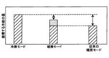
- the heat release amount adjustment unit causes the heat release amount in the heating radiator to increase more than the heat release amount in the heat medium radiator in the heating mode in which the heat exchange target fluid is heated.
- the heat release amount adjustment unit reduces the heat release amount in the heating radiator in the cooling mode for cooling the heat exchange target fluid, rather than the heating mode.
- the heat release amount adjustment unit adjusts the amount of heat release to the heat exchange target fluid of the heat of the high-pressure refrigerant in the heating radiator, without switching the refrigerant circuit of the refrigeration cycle apparatus, the cooling target fluid Can be switched between a heating mode for heating and a cooling mode for cooling.
- the heating mode can be realized by increasing the amount of heat release in the heating radiator and heating the fluid to be exchanged with heat using the heating radiator, reducing the amount of heat dissipation in the heating radiator and reducing the amount of heat to the evaporator.
- the cooling mode can be realized by cooling the heat exchange target fluid. For this reason, it is not necessary to change the function of the same heat exchanger according to the operation mode, and the pressure adjustment valve and the switching valve for switching the refrigerant circuit of the refrigeration cycle apparatus become unnecessary.
- the cycle configuration of the refrigeration cycle apparatus can be simplified, and complicated control for switching the refrigerant circuit of the refrigeration cycle apparatus becomes unnecessary. Therefore, in the refrigeration cycle apparatus configured to be able to switch between the heating mode and the cooling mode, it is possible to provide the refrigeration cycle apparatus capable of simplifying the circuit configuration and the switching control.
- FIG. 1 is an overall block diagram of an air conditioner in accordance with at least one embodiment of the present disclosure.
- FIG. 2 is a block diagram illustrating the electrical control of the air conditioner of at least one embodiment of the present disclosure. It is the graph which showed the quantity of the refrigerant which circulates through a frozen cycle device.
- BRIEF DESCRIPTION OF THE DRAWINGS It is a whole block diagram of the air conditioner which concerns on at least one embodiment of this indication.
- BRIEF DESCRIPTION OF THE DRAWINGS It is a whole block diagram of the air conditioner which concerns on at least one embodiment of this indication.
- BRIEF DESCRIPTION OF THE DRAWINGS It is a whole block diagram of the air conditioner which concerns on at least one embodiment of this indication.
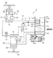
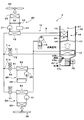
- FIGS. 1 and 2 An air conditioner 1 equipped with a refrigeration cycle apparatus 10 according to a first embodiment of the present disclosure will be described using FIGS. 1 and 2.
- the air conditioner 1 shown in FIG. 1 is applied to a vehicle air conditioner.
- the air conditioning system for vehicles is an air conditioning system which adjusts a vehicle interior space to appropriate temperature.
- the air conditioner 1 of the present embodiment is mounted on a hybrid vehicle that obtains a driving force for vehicle traveling from an engine (in other words, an internal combustion engine) and a traveling electric motor.
- the hybrid vehicle of the present embodiment is configured as a plug-in hybrid vehicle capable of charging a battery (in other words, an on-board battery) mounted on the vehicle with electric power supplied from an external power supply (in other words, a commercial power supply) It is done.
- a battery in other words, an on-board battery
- an external power supply in other words, a commercial power supply
- a lithium ion battery can be used as the battery.
- the driving force output from the engine is used not only for driving the vehicle but also for operating the generator.
- the electric power generated by the generator and the electric power supplied from the external power supply can be stored in the battery, and the electric power stored in the battery is not only the electric motor for traveling but also the electric motor constituting the refrigeration cycle apparatus 10 It is supplied to various in-vehicle devices including formula components.
- the air conditioner 1 operates in a cooling mode for cooling the passenger compartment, which is an air conditioning target space (i.e., a cooling mode for cooling the air, which is a heat exchange target fluid), and a heating mode for heating the passenger compartment (i.e., heat exchange It is possible to switch between the operation of the heating mode for heating the air, which is the target fluid, and the operation.
- the air conditioner 1 includes a refrigeration cycle apparatus 10, a high temperature side heat medium flow passage 20, a low temperature side heat medium flow passage 30, and an indoor air conditioning unit 40.
- the refrigeration cycle apparatus 10 includes a compressor 11, an indoor condenser 12 (heat radiator), an outdoor condenser 13 (heat medium radiator), a pressure reducing valve 14 (pressure reducing portion), and an evaporator 15 in the refrigerant flow path 9.
- the accumulators 16 are arranged in this order.
- a fluorocarbon-based refrigerant is used as the refrigerant, and a subcritical refrigeration cycle in which the high-pressure refrigerant pressure does not exceed the critical pressure of the refrigerant is configured.
- the compressor 11 is an electric compressor driven by electric power supplied from a battery, and sucks, compresses and discharges the refrigerant of the refrigeration cycle apparatus 10. The operation of the compressor 11 is controlled by a control signal output from the controller 50.
- the refrigerant inlet side of the indoor condenser 12 is connected to the discharge port of the compressor 11.
- the indoor condenser 12 is disposed in a casing 41 of an indoor air conditioning unit 40 described later.
- the indoor condenser 12 exchanges heat between the high-temperature and high-pressure refrigerant (hereinafter, abbreviated as high-pressure refrigerant) discharged from the compressor 11 and the blast air, which is a heat exchange target fluid, at least in the heating mode. It is a radiator for heating which radiates heat to the blast air to heat the blast air. When the heat of the high pressure refrigerant is dissipated to the blast air, the high pressure refrigerant condenses.
- the refrigerant inlet side of the outdoor condenser 13 is connected to the refrigerant outlet side of the indoor condenser 12.
- the outdoor condenser 13 is disposed outside the vehicle.
- the outdoor condenser 13 exchanges heat between the high-pressure refrigerant flowing out of the indoor condenser 12 and the coolant, which is the high-temperature side heat medium flowing in the high-temperature side heat medium flow passage 20, at least in the cooling mode. It is a radiator for heat medium which radiates the heat which it has to cooling water.
- the cooling water flowing in the high temperature side heat medium flow passage 20 and the cooling water flowing in the low temperature side heat medium flow passage 30 described later use a liquid containing at least ethylene glycol, dimethylpolysiloxane or nanofluid, or an antifreeze liquid It is done.
- the high temperature side heat medium flow passage 20 is an annular flow passage for circulating the cooling water between the outdoor condenser 13 and the high temperature side radiator 22 described later.
- the outdoor condenser 13 the heating device 24, the high temperature side three-way valve 23, the high temperature side radiator 22, and the high temperature side pump 21 are arranged in this order.
- the high temperature side pump 21 circulates the cooling water in the high temperature side heat medium flow path 20 by sucking the cooling water and discharging it to the outdoor condenser 13 side.
- the high temperature side pump 21 is an electric pump, and is a high temperature side flow rate adjustment unit that adjusts the flow rate of the cooling water circulating in the high temperature side heat medium flow passage 20.
- the high temperature side radiator 22 exchanges heat between the cooling water and the outside air blown from the high temperature side blower 26. That is, in the high temperature side radiator 22, the cooling water heated by the outdoor condenser 13 exchanges heat with the outside air and is cooled.
- the high temperature side blower 26 is an electric blower which drives a fan by an electric motor, and its operation is controlled by a control signal output from the control device 50.
- the high temperature side radiator 22 and the high temperature side blower 26 are disposed on the front side in the vehicle bonnet. Therefore, the traveling wind can be applied to the high temperature side radiator 22 when the vehicle travels.
- the high temperature side heat medium flow passage 20 is provided with a high temperature side bypass flow passage 25 for circulating the cooling water discharged by the high temperature side pump 21 by bypassing the high temperature side radiator 22.
- the inlet side of the high temperature side bypass flow passage 25 is connected to the inlet side of the high temperature side radiator 22.
- the outlet side of the high temperature side bypass flow passage 25 is connected to the outlet side of the high temperature side radiator 22.
- the high temperature side three-way valve 23 is a high temperature side adjusting valve that adjusts the flow rate of the cooling water flowing into the high temperature side radiator 22 by adjusting the flow rate of the cooling water flowing into the high temperature side bypass flow passage 25.
- the operation of the high temperature side three-way valve 23 is controlled by a control signal output from the controller 50.
- the heating device 24 supplies heat to the cooling water of the high temperature side heat medium flow passage 20.
- a heating device 24 an on-vehicle device with heat generation at the time of operation, a PTC heater (electrical heater) that generates heat by being supplied with power, or the like can be adopted. More specifically, a battery, an inverter that is a frequency conversion unit, and a traveling electric motor that outputs a driving force for traveling can be adopted as the on-vehicle device. These on-vehicle devices are cooled by radiating heat to the cooling water of the high temperature side heat medium flow passage 20.
- the refrigerant inlet side of the pressure reducing valve 14 is connected to the refrigerant outlet side of the outdoor condenser 13.
- the pressure reducing valve 14 is a pressure reducing unit that reduces the pressure and expands the liquid phase refrigerant flowing out of the outdoor condenser 13. That is, the pressure reducing valve 14 reduces the pressure of the refrigerant on the downstream side of the indoor condenser 12 and the outdoor condenser 13.
- the pressure reducing valve 14 is an electric variable throttle mechanism whose operation is controlled by a control signal output from the control device 50, and includes a valve body and an electric actuator.
- the valve body is configured to be capable of changing the passage opening degree of the refrigerant passage (in other words, the throttle opening degree).
- the electric actuator has a stepping motor that changes the throttle opening of the valve body.
- the refrigerant inlet side of the evaporator 15 is connected to the refrigerant outlet side of the pressure reducing valve 14.
- the evaporator 15 evaporates the low pressure refrigerant by heat exchange between the heat of the low pressure refrigerant decompressed by the pressure reducing valve 14 and the cooling water which is the low temperature side heat medium flowing through the low temperature side heat medium channel 30.
- the low-pressure refrigerant absorbs heat from the cooling water and evaporates, whereby the cooling water is cooled.
- the low temperature side heat medium flow channel 30 is an annular flow channel, and cooling water which is a low temperature side heat medium circulates.
- the evaporator 15, the low temperature side pump 31, the cooler core channel three-way valve 32, and the low temperature side radiator 33 are arranged in this order of arrangement.
- the low temperature side pump 31 is a heat medium pump which sucks in and discharges the cooling water.
- the low temperature side pump 31 is an electric pump, and is a low temperature side flow rate adjustment unit that adjusts the flow rate of the cooling water circulating in the low temperature side heat medium flow passage 30.
- a cooler core flow channel 34 for circulating the cooling water which is the low temperature side heat medium discharged by the low temperature side pump 31 by bypassing the low temperature side radiator 33. Both ends of the cooler core flow passage 34 are connected to the low temperature side heat medium flow passage 30 on the inflow side and the outflow side of the low temperature side radiator 33.
- the cooler core flow path three-way valve 32 is a cooler core flow control valve that adjusts the flow rate of the cooling water flowing into the low temperature side radiator 33 by adjusting the flow rate of the cooling water as the low temperature side heat medium flowing into the cooler core flow path 34 is there.
- the operation of the cooler core flow path three-way valve 32 is controlled by a control signal output from the controller 50.
- the low temperature side radiator 33 exchanges heat between the cooling water as the low temperature side heat medium and the outside air blown from the low temperature side fan 36. Therefore, the cooling water cooled by the evaporator 15 is allowed to flow into the low temperature side radiator 33 to exchange heat with the outside air, whereby the low temperature cooling water can absorb heat from the outside air.
- the low temperature side fan 36 blows the outside air toward the low temperature side radiator 33.
- the low temperature side fan 36 is an electric fan that drives a fan by an electric motor, and its operation is controlled by a control signal output from the controller 50.
- the low temperature side radiator 33 and the low temperature side blower 36 are disposed on the front side in the vehicle bonnet, similarly to the high temperature side radiator 22 and the high temperature side blower 26. Therefore, the traveling wind can be applied to the low temperature side radiator 33 when the vehicle travels.
- the cooler core 35 exchanges heat between the cooling water of the low temperature side heat medium flow passage 30 and the blowing air which is a heat exchange target fluid blown into the vehicle compartment. Therefore, blowing air can be cooled by causing the cooling water cooled by the evaporator 15 to flow into the cooler core 35. That is, in the evaporator 15 according to the present embodiment, the heat of the blown air can be absorbed by the refrigerant decompressed by the pressure reducing valve 14 through the cooling water, and the refrigerant can be evaporated.
- the refrigerant inlet side of the accumulator 16 is connected to the refrigerant outlet side of the evaporator 15. That is, the accumulator 16 is provided between the evaporator 15 and the compressor 11, that is, on the upstream side of the compressor 11.
- the accumulator 16 is a gas-liquid separation unit that separates gas and liquid of the refrigerant that has flowed into the inside, and is a liquid storage unit that stores excess refrigerant in the cycle.
- the suction port side of the compressor 11 is connected to the gas phase refrigerant outlet of the accumulator 16. Therefore, the accumulator 16 suppresses the suction of the liquid-phase refrigerant into the compressor 11 and functions to prevent the liquid compression in the compressor 11.
- the required refrigerant flow rate for circulating the cycle in the cooling mode is larger than the required refrigerant flow rate for circulating the cycle in the heating mode. Therefore, in the heating mode, the surplus liquid phase refrigerant in the cycle is stored to absorb the fluctuation of the required refrigerant flow rate.
- the indoor air conditioning unit 40 is for blowing out the blowing air whose temperature has been adjusted by the refrigeration cycle apparatus 10 into the vehicle interior which is the space to be air conditioned.
- the indoor air conditioning unit 40 is disposed inside the instrument panel at the foremost part of the vehicle interior.
- the indoor air conditioning unit 40 is configured by housing the cooler core 35, the indoor condenser 12 and the like in a casing 41 forming the outer shell thereof.
- the casing 41 is an air passage forming portion that forms an air passage for blowing air blown into the vehicle compartment, which is a space to be air conditioned.
- the casing 41 has a certain degree of elasticity and is formed of a resin (for example, polypropylene) which is excellent in strength.
- Inside / outside air switching as an inside / outside air switching unit to switch and introduce inside air (air within the air conditioned space) and outside air (air outside the air conditioned space) into the casing 41 on the most upstream side of the air flow inside the casing 41 A device 43 is arranged.
- the inside / outside air switching device 43 is formed with an inside air introduction port 43 b for introducing inside air into the casing 41 and an outside air introduction port 43 c for introducing outside air into the casing 41.
- an inside / outside air switching door 43a is provided in the inside / outside air switching device 43 so as to be able to swing.
- the inside / outside air switching door 43a is driven by an electric actuator whose operation is controlled by a control signal output from the control device 50.
- the inside / outside air switching device 43 switches between the outside air mode and the inside air mode by means of the inside / outside air switching door 43a.
- the outside air mode is a mode in which the inside air introduction port 43b is closed by the inside / outside air switching door 43a and the outside air introduction port 43c is opened to introduce outside air which is air outside the space to be air conditioned into the casing 41.
- the inside air mode is a mode in which the outside air introduction port 43c is closed by the inside / outside air switching door 43a and the inside air introduction port 43b is opened to introduce inside air, which is air in the space to be air conditioned, into the casing 41.
- the inside / outside air switching device 43 continuously adjusts the opening areas of the inside air introduction port 43b and the outside air introduction port 43c by the inside / outside air switching door 43a, and the ratio of the inside air flow rate to the outside air flow rate is continuous. Can be changed to
- an air conditioning blower 42 for directing the air drawn in via the inside / outside air switching device 43 into the space to be air-conditioned is arranged.
- the air conditioning blower 42 is an electric blower that drives a centrifugal multi-blade fan (sirocco fan) by an electric motor, and the number of rotations (air flow amount) is controlled by the control voltage output from the control device 50.
- the cooler core 35 is disposed downstream of the air flow of the air conditioning blower. Further, the downstream side of the cooler core 35 of the air passage formed in the casing 41 is bifurcated, and the indoor condenser passage 45 and the cold air bypass passage 46 are formed in parallel.
- the indoor condenser 12 is disposed in the indoor condenser passage 45. That is, the indoor condenser passage 45 is an air passage for circulating the blown air which exchanges heat with the refrigerant in the indoor condenser 12.
- the cooler core 35 and the indoor condenser 12 are disposed in this order with respect to the flow of the blowing air. In other words, the cooler core 35 is disposed upstream of the indoor condenser 12 in the flow of the blown air.
- the indoor condenser passage 45 constitutes a part of an air passage through which the blown air flows in the order of the cooler core 35 ⁇ the indoor condenser 12.
- the cold air bypass passage 46 is an air passage that causes the blown air that has passed through the cooler core 35 to bypass the indoor condenser 12 and flow downstream.
- the air flow downstream of the cooler core 35 and the air flow upstream of the indoor condenser 12 is controlled by the control signal output from the control device 50 so that the indoor condenser of the air after passing through the cooler core 35
- An air mix door 44 is disposed to adjust the air volume ratio for passing 12.
- a mixing channel 47 is formed in the casing 41 on the downstream side of the merging portion of the indoor condenser passage 45 and the cold air bypass passage 46. In the mixing flow path 47, the blast air heated in the indoor condenser 12 and the blast air not heated in the indoor condenser 12 passing through the cold air bypass passage 46 are mixed.
- a plurality of opening holes are disposed for blowing the air (air-conditioned air) mixed in the mixing space into the vehicle compartment as the air-conditioned space.
- the face opening hole is an opening hole for blowing the conditioned air toward the upper body of the passenger in the vehicle room which is the space to be conditioned.
- the foot opening hole is an opening hole for blowing the conditioned air toward the feet of the occupant.
- the defroster opening hole is an opening hole for blowing the conditioned air toward the inner side surface of the vehicle front windshield.
- the temperature of the conditioned air mixed in the mixing space is adjusted by adjusting the air volume ratio between the air volume passing the indoor condenser 12 and the air volume passing the cold air bypass passage 46 by the air mix door 44.
- the temperature of the conditioned air blown out from the outlets into the vehicle room which is the space to be conditioned is adjusted.
- the air mix door 44 functions as a temperature control unit that adjusts the temperature of the conditioned air blown into the vehicle compartment, which is the space to be conditioned.
- the air mix door 44 has an electric actuator for driving the air mix door. The operation of the electric actuator is controlled by a control signal output from the controller 50.
- the electric actuator for driving the air mix door displaces the air mix door 44 so as to open the indoor condenser passage 45 and close the cold air bypass passage 46, the air which has passed through the cooler core 35 is sent to the indoor condenser 12.
- the air can be blown, and the heat of the high-pressure refrigerant can be dissipated to the blowing air in the indoor condenser 12.
- the air mix door 44 functions as a heat release amount adjustment unit that adjusts the amount of heat release that the high pressure refrigerant releases to the blowing air in the indoor condenser 12.
- a defroster door (not shown) for adjusting the opening area is arranged.
- These face door, foot door, and defroster door constitute an outlet mode switching door for switching the outlet mode.
- the face door, the foot door, and the defroster door are each connected to an electric actuator for driving the air outlet mode door via a link mechanism or the like, and are rotationally operated in conjunction with each other.
- the operation of the electric actuator is also controlled by a control signal output from the control device 50.
- the air outlet mode switched by the air outlet mode switching door includes a face mode, a bi-level mode, a foot mode and the like.
- the face mode is an outlet mode in which the face outlet is fully opened and blowing air is blown from the face outlet toward the upper body of the vehicle occupant.
- the bi-level mode is an air outlet mode in which both the face air outlet and the foot air outlet are opened to blow air toward the upper body and the foot of the passenger in the vehicle compartment.
- the foot mode is an outlet mode in which the air outlet is blown out from the foot outlet toward the foot of the passenger in the passenger compartment with the foot outlet fully open.
- the occupant manually operates the air outlet mode switching switch provided in the operation unit 60 shown in FIG. 2 to fully open the defroster air outlet and blow air from the defroster air outlet onto the inner surface of the vehicle windshield. It can also be done.
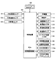
- the control device 50 shown in FIG. 2 is composed of a known microcomputer including a CPU, a ROM, a RAM and the like, and peripheral circuits thereof.
- the control device 50 performs various operations and processing based on the control program stored in the ROM.
- Various control target devices are connected to the output side of the control device 50.
- the control device 50 is a control unit that controls the operation of various control target devices.
- the control target devices controlled by the control device 50 include the compressor 11, the pressure reducing valve 14, the high temperature side pump 21, the high temperature side three-way valve 23, the high temperature side blower 26, the low temperature side pump 31, the cooler core flow path three way valve 32, the low temperature side
- the control device 50 is integrally configured with a control unit that controls various control target devices connected to the output side.
- operation of each control object apparatus among the control apparatuses 50 comprises the control part which controls the action
- the software and hardware which control the air mix door 44 among the control apparatuses 50 are the heat release amount control part 60a.
- control sensor groups such as an inside air temperature sensor 51, an outside air temperature sensor 52, and a solar radiation amount sensor 53 are connected to the input side of the control device 50.
- the inside air temperature sensor 51 detects a vehicle interior temperature Tr.
- the outside air temperature sensor 52 detects an outside air temperature Tam.
- the solar radiation amount sensor 53 detects the solar radiation amount Ts in the vehicle compartment.
- An operation unit 60 is connected to the input side of the control device 50.
- the operating unit 60 is operated by the occupant.
- the operation unit 60 is disposed in the vicinity of an instrument panel at the front of the vehicle interior.
- An operation signal from the operation unit 60 is input to the control device 50.
- the operation unit 60 is provided with an air conditioner switch, a temperature setting switch, and the like.
- the air conditioner switch sets whether to cool the blowing air in the indoor air conditioning unit.
- the temperature setting switch sets the set temperature of the vehicle interior.
- control device 50 Based on the detection signal detected by the control sensor group and the operation signal from operation unit 60, control device 50 calculates target blowout temperature TAO of the air to be blown into the vehicle compartment. Then, the operation mode is switched based on the target blowout temperature TAO and the like. Furthermore, in the present embodiment, the heating mode is switched to the extremely low temperature mode when the outside temperature is lower than or equal to a predetermined reference outside temperature. Each operation mode will be described below.
- the control device 50 determines the operation states (control signals to be output to various control devices) of the various control target devices based on the detection signal and the target blowing temperature TAO and the like. Specifically, the control device 50 operates the compressor 11, the high temperature side pump 21, and the low temperature side pump 31 so as to exert the discharge capacity in the predetermined cooling mode. The control device 50 determines a control signal to be output to the pressure reducing valve 14 so as to have a predetermined throttle opening degree for the cooling mode.
- the control device 50 closes the high temperature side bypass flow passage 25 and controls the operation of the high temperature side three-way valve 23 so that the coolant flows into the high temperature side radiator 22.
- the controller 50 opens the cooler core flow passage 34 and controls the operation of the cooler core flow passage three-way valve 32 so that the cooling water flows into the cooler core 35.
- control device 50 closes the indoor condenser passage 45 (state shown by the solid line in FIG. 1), and the air mix door 44 so that the total flow rate of the blown air passing through the cooler core 35 flows into the cold air bypass passage 46. Control the operation of the
- the high pressure refrigerant discharged from the compressor 11 flows into the indoor condenser 12.
- the air mix door 44 is displaced so as to allow the blown air to flow into the cold air bypass passage 46. Therefore, the high-pressure refrigerant that has flowed into the indoor condenser 12 flows out of the indoor condenser 12 with little heat release to the blown air.
- the high temperature side three-way valve 23 is switched to flow the cooling water into the high temperature side radiator 22. Therefore, the high pressure refrigerant flowing into the outdoor condenser 13 dissipates heat to the cooling water cooled by the high temperature side radiator 22 and condenses. Thereby, the heat which the high pressure refrigerant has in the outdoor condenser 13 is absorbed by the cooling water.
- the heat release amount of the high pressure refrigerant in the indoor condenser 12 is smaller than the heat release amount of the high pressure refrigerant in the outdoor condenser 13.
- the pressure reducing valve 14 is in a squeezed state in which the pressure reducing valve 14 exerts a pressure reducing function, the refrigerant flowing into the pressure reducing valve 14 is reduced in pressure to be a low pressure refrigerant.
- the pump 31 is operating. Therefore, the low pressure refrigerant flowing into the evaporator 15 absorbs heat from the cooling water circulating in the low temperature side heat medium flow passage 30 and evaporates. Thereby, the cooling water circulating in the low temperature side heat medium channel 30 is cooled.
- the cooler core flow path three-way valve 32 is switched to flow the cooling water into the cooler core 35. Therefore, the cooling water cooled by the evaporator 15 exchanges heat with the blowing air at the cooler core 35 and absorbs heat. Thereby, the blowing air is cooled.
- the refrigerant flowing out of the evaporator 15 flows into the accumulator 16 to be separated into gas and liquid.
- the gas phase refrigerant separated by the accumulator 16 is sucked into the compressor 11 and compressed again.
- the blowing air cooled by the cooler core 35 can be blown into the vehicle compartment. Thereby, cooling of the vehicle interior can be realized.
- the control device 50 determines the operation states (control signals to be output to various control devices) of the various control target devices based on the detection signal and the target blowout temperature TAO and the like. Specifically, the control device 50 operates the compressor 11, the high temperature side pump 21, and the low temperature side pump 31 so as to exert the discharge capacity in the predetermined heating mode. The control device 50 determines a control signal to be output to the pressure reducing valve 14 so as to have a predetermined throttle opening degree for the heating mode.
- the control device 50 closes the high temperature side bypass flow passage 25 and controls the operation of the high temperature side three-way valve 23 so that the coolant flows into the high temperature side radiator 22.
- the controller 50 closes the cooler core flow passage 34 and controls the operation of the cooler core flow passage three-way valve 32 so that the cooling water flows into the low temperature side radiator 33.
- the controller 50 closes the cold air bypass passage 46 (the state shown by the broken line in FIG. 1), and the air mix door 44 allows the entire flow of the blown air passing through the cooler core 35 to flow into the indoor condenser passage 45. Control the operation of the Therefore, in the heating mode, the flow rate of the blown air flowing into the indoor condenser 12 is higher than in the cooling mode. In other words, in the cooling mode, the flow rate of the blown air flowing into the indoor condenser 12 is smaller than in the heating mode.
- the high pressure refrigerant discharged from the compressor 11 flows into the indoor condenser 12.
- the air mix door 44 is displaced so as to allow the blown air to flow into the indoor condenser passage 45. Therefore, the high-pressure refrigerant flowing into the indoor condenser 12 releases heat to the blown air and condenses. Thereby, the blowing air which flows through the indoor condenser passage 45 is heated.
- the high temperature side three-way valve 23 is switched to flow the cooling water into the high temperature side radiator 22. Therefore, the high-pressure refrigerant flowing into the outdoor condenser 13 further radiates heat to the cooling water cooled by the high temperature side radiator 22 and condenses, as in the cooling mode. Thereby, the heat which the high pressure refrigerant has in the outdoor condenser 13 is absorbed by the cooling water.
- the heat release amount of the high pressure refrigerant in the indoor condenser 12 is larger than the heat release amount of the high pressure refrigerant in the outdoor condenser 13. Therefore, in the heating mode, the dryness of the high pressure refrigerant on the inlet side of the outdoor condenser 13 is smaller than that in the cooling mode.
- the heat release amount of the high-pressure refrigerant in the indoor condenser 12 increases more than in the cooling mode.
- the heat release amount of the high-pressure refrigerant in the indoor condenser 12 is smaller than in the heating mode.
- the high pressure refrigerant flowing out of the outdoor condenser 13 is reduced in pressure by the pressure reducing valve 14 to be a low pressure refrigerant, as in the cooling mode.
- the low pressure refrigerant reduced in pressure by the pressure reducing valve 14 flows into the evaporator 15.
- the low temperature side pump 31 is operating. Therefore, the low pressure refrigerant flowing into the evaporator 15 absorbs heat from the cooling water circulating in the low temperature side heat medium flow passage 30 and evaporates. Thereby, the cooling water circulating in the low temperature side heat medium channel 30 is cooled.
- the cooler core flow path three-way valve 32 is switched so as to allow the coolant to flow into the low temperature side radiator 33. Therefore, the cooling water cooled by the evaporator 15 exchanges heat with the outside air in the low temperature side radiator 33 and is heated. The refrigerant flowing out of the evaporator 15 flows into the accumulator 16 to be separated into gas and liquid. The gas phase refrigerant separated by the accumulator 16 is sucked into the compressor 11 and compressed again.
- the blowing air heated by the indoor condenser 12 can be blown out into the vehicle compartment. Thereby, heating of the vehicle interior can be realized. Furthermore, the refrigerant can be condensed by the outdoor condenser 13 and the condensed refrigerant can be retained in the outdoor condenser 13.
- the control device 50 determines the operation states (control signals to be output to the various control devices) of the various control target devices, as in the heating mode. In the low temperature heating mode, the control device 50 opens the high temperature side bypass flow passage 25 and controls the operation of the high temperature side three-way valve 23 so that the cooling water bypasses the high temperature side radiator 22.
- the high pressure refrigerant discharged from the compressor 11 flows into the indoor condenser 12.
- the air mix door 44 is displaced so as to allow the blown air to flow into the indoor condenser passage 45. Therefore, the high-pressure refrigerant flowing into the indoor condenser 12 releases heat to the blown air and condenses. Thereby, the blowing air which flows through the indoor condenser passage 45 is heated.
- the temperature of the blowing air flowing into the indoor condenser 12 is low. Therefore, the high pressure refrigerant flowing into the indoor condenser 12 becomes a liquid phase refrigerant having a degree of subcooling.
- the high-pressure refrigerant flowing out of the indoor condenser 12 flows into the outdoor condenser 13.
- the high temperature side three-way valve 23 is switched to flow the cooling water into the high temperature side bypass flow passage 25. Therefore, the high pressure refrigerant flowing into the outdoor condenser 13 is heated by the cooling water heated by the heating device 24.
- the subsequent operation is similar to the heating mode.
- the blowing air heated by the indoor condenser 12 can be blown out into the vehicle compartment. Thereby, heating of the vehicle interior can be realized. Furthermore, the refrigerant can be heated by the outdoor condenser 13 to raise the high pressure side refrigerant pressure of the cycle. Therefore, the refrigerant condensation temperature in the indoor condenser 12 can be raised to efficiently raise the temperature of the blown air.
- the air mix door 44 which is the adjustment unit for heat release causes the amount of heat release in the indoor condenser 12 to be larger than the amount of heat release in the outdoor condenser 13.
- the air mix door 44 reduces the heat release amount in the indoor condenser 12 more than in the heating mode.
- the refrigerant circuit of the refrigeration cycle apparatus 10 does not need to be switched, and the heating mode is It is possible to switch between the cooling mode.
- the heating mode can be realized by increasing the heat release amount in the indoor condenser 12 and heating the blowing air in the indoor condenser 12, reducing the heat release amount in the indoor condenser 12, and
- the cooling mode can be realized by cooling the blowing air by the heat absorption function of the refrigerant.
- the pressure adjustment valve and the switching valve for switching the refrigerant circuit according to the operation mode become unnecessary.
- the cycle configuration of the refrigeration cycle apparatus 10 can be simplified, and complicated control for switching the refrigerant circuit of the cycle apparatus 10 is not necessary.
- the air mix door 44 makes the dryness of the refrigerant on the inlet side of the outdoor condenser 13 smaller than that in the cooling mode. Thereby, the refrigerant of the liquid phase can be retained in the outdoor condenser 13 in the heating mode.
- the required refrigerant flow rate for circulating the cycle in the cooling mode is larger than the required refrigerant flow rate for circulating the cycle in the heating mode.
- the outdoor condenser 13 can store the condensed refrigerant.
- the minimum required capacity of the accumulator 16 can be reduced as compared with the conventional refrigeration cycle apparatus, and hence the capacity of the accumulator 16 can be reduced.
- the accumulator 16 can be miniaturized.
- the indoor condenser 12 and the outdoor condenser are arranged to absorb all the fluctuation of the amount of refrigerant circulating in the refrigeration cycle apparatus 10 in the outdoor condenser 13.
- the accumulator 16 can be eliminated if the amount of heat release at 13 is adjusted.
- the refrigeration cycle apparatus 10 can be further miniaturized, and the manufacturing cost of the refrigeration cycle apparatus 10 can be reduced.
- the air mix door 44 adjusts the flow rate of the blowing air passing through the indoor condenser 12. Then, in the cooling mode, the air mix door 44 reduces the flow rate of the blowing air passing through the indoor condenser 12 more than in the heating mode. As a result, it is possible to easily configure a heat release amount adjustment unit that adjusts the amount of heat release from the high pressure refrigerant in the indoor condenser 12 to the blown air.
- the heating device 24 heats the high pressure refrigerant flowing out of the indoor condenser 12 in the heating at the very low temperature mode.
- the high pressure side refrigerant pressure of the refrigeration cycle apparatus 10 can be raised. Therefore, the refrigerant condensation temperature in the indoor condenser 12 can be raised to efficiently raise the temperature of the blowing air, and the heating performance of the air conditioner 1 can be improved.
- the heating device 24 is disposed in the high temperature side heat medium flow passage 20, and heats the high pressure refrigerant by heating the cooling water.
- the high pressure refrigerant can be heated in the extremely low temperature heating mode with a simple configuration.
- the heating device 24 is a vehicle-mounted device, the high-pressure refrigerant can be heated by the exhaust heat of the vehicle-mounted device, so energy for heating the high-pressure refrigerant becomes unnecessary.
- the high temperature side heat medium flow channel 20 of the present embodiment has a high temperature side radiator 22, a high temperature side bypass flow channel 25, and a high temperature side three-way valve 23. According to this, even when it is difficult to adjust the heating capacity as in the case where an on-vehicle device is adopted as the heating device 24, it is possible to easily adjust the amount of heating of the cooling water.
- the low temperature side radiator 33 for cooling the heat exchange with the outside air by cooling the cooling water, and the low temperature side heat medium for circulating the cooling water between the evaporator 15 and the low temperature side radiator 33
- a flow path 30 and a low temperature side pump 31 which discharges the cooling water and circulates the cooling water in the low temperature side heat medium flow path 30 are provided.
- the cooling water circulating through the low temperature side heat medium flow passage 30 is heated in heat exchange with the outside air in the low temperature side radiator 33, and heat is absorbed by the low pressure refrigerant in the evaporator 15 be able to.
- the cooling water discharged by the low temperature side pump 31 is connected to the low temperature side heat medium flow channel 30 at both ends on the inflow side and the outflow side of the low temperature side radiator 33.
- a cooler core flow path 34 is provided to bypass the low temperature side radiator 33 for circulation.
- a cooler core 35 is disposed which causes heat to be exchanged between the cooling water and the blowing air so that the heat contained in the blowing air is absorbed by the cooling water.
- a cooler core flow path three-way valve 32 is disposed in the low temperature side heat medium flow path 30 for adjusting the flow rate of the cooling water flowing into the cooler core flow path 34 and the flow rate of the cooling water flowing into the low temperature side radiator 33 .
- the cooler core flow path three-way valve 32 opens the cooler core flow path 34 and closes the flow path on the inflow side of the low temperature side radiator 33 of the low temperature side heat medium flow path 30. Is circulated, and the cooled air flowing through the casing 41 can be cooled by the cooler core 35.
- the cooler core flow path three-way valve 32 closes the cooler core flow path 34 and opens the low temperature side heat medium flow path 30 on the inflow side of the low temperature side radiator 33.
- the air does not flow, and the blown air flows into the indoor condenser 12 without being cooled by the cooler core 35. Therefore, in the heating mode, the blown air is prevented from being unnecessarily cooled by the cooler core 35, and the heating capacity of the air conditioner 1 can be improved.
- the indoor condenser 12 exchanges heat between the high pressure refrigerant and the blowing air to heat the blowing air. According to this, since the heat of the high pressure refrigerant can be dissipated directly to the blast air, for example, the heat of the high pressure refrigerant can be indirectly dissipated to the blast air through the heat medium or the like. Thus, the heating capacity of the blown air of the refrigeration cycle apparatus 10 can be improved.
- FIG. 4 The refrigeration cycle apparatus 10 of the air conditioner 2 of the second embodiment is obtained by adding a refrigerant bypass flow passage 17 and a refrigerant three-way valve 18 to the air conditioner 1 of the first embodiment.
- the other configuration is the same as the air conditioner 1 of the first embodiment.
- the refrigerant bypass flow passage 17 is a flow passage that causes the high-pressure refrigerant discharged by the compressor 11 to flow around the indoor condenser 12 to the outdoor condenser 13.
- the refrigerant bypass flow path 17 is connected to the inflow side and the outflow side of the indoor condenser 12 of the refrigerant flow path 9.
- the refrigerant three-way valve 18 adjusts the flow rate of the high pressure refrigerant flowing into the refrigerant bypass flow path 17 to thereby control the flow rate of the high pressure refrigerant flowing into the indoor condenser 12 among the high pressure refrigerant discharged from the compressor 11 It is a flow control valve that adjusts the flow rate of the high pressure refrigerant flowing into the outdoor condenser 13 among the high pressure refrigerant discharged from 11.
- the refrigerant three-way valve 18 can adjust the amount of heat released from the high pressure refrigerant in the indoor condenser 12 to the blast air by adjusting the flow rate of the high pressure refrigerant flowing into the indoor condenser 12. Therefore, the refrigerant three-way valve 18 of the present embodiment functions as a heat release amount adjustment unit that adjusts the amount of heat release from the high pressure refrigerant to the blown air in the indoor condenser 12.
- the refrigerant three-way valve 18 reduces the flow rate of the high-pressure refrigerant flowing into the indoor condenser 12 more than the heating mode (including the cryogenic temperature heating mode).
- the refrigerant three-way valve 18 closes the refrigerant bypass flow passage 17 and opens the inflow side of the indoor condenser 12.
- the entire amount of the high pressure refrigerant discharged by the compressor 11 flows into the indoor condenser 12, and in the indoor condenser 12, the high pressure refrigerant and the blowing air exchange heat to heat the blowing air.
- the refrigerant three-way valve 18 opens the refrigerant bypass flow passage 17 and closes the inflow side of the indoor condenser 12.
- the entire amount of the high-pressure refrigerant discharged by the compressor 11 flows into the refrigerant bypass flow path 17 and flows into the outdoor condenser 13.
- the flow rate of the high-pressure refrigerant flowing into the indoor condenser 12 is adjusted by the refrigerant three-way valve 18, and the high-pressure refrigerant in the indoor condenser 12 is discharged to the blowing air.
- the amount of heat it is possible to switch between the heating mode and the cooling mode. Therefore, the same effect as that of the first embodiment can be obtained.
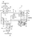
- FIG. 5 In the air conditioner 3 of the third embodiment, a branching portion 71a, a refrigerant flow path 71 for cooling, a pressure reducing valve 72 for cooling, an indoor evaporator 73, and the like are added to the air conditioner 1 of the first embodiment.
- the road three-way valve 32, the cooler core flow passage 34, the cooler core 35 and the like are eliminated.
- the branch part 71a is a part which branches the flow of the refrigerant
- the inlet side of the pressure reducing valve 14 is connected to one outlet of the branch portion 71a.
- the inlet side of the cooling pressure reducing valve 72 is connected to the other outlet of the branch portion 71a. For this reason, the pressure reducing valve 14 and the cooling pressure reducing valve 72 are disposed in parallel to the refrigerant flow.
- the cooling refrigerant channel 71 is a refrigerant passage that connects one outlet of the branch portion 71a and the suction side of the compressor 11 (specifically, the inlet side of the accumulator 16).
- a cooling pressure-reduction valve 72 and an indoor evaporator 73 are arranged in this order from the side of the branch portion 71a.
- the cooling pressure reducing valve 72 is a pressure reducing portion that decompresses and expands the refrigerant branched by the branching portion 71 a at least in the cooling mode.
- the cooling pressure reducing valve 72 is an electric variable throttle mechanism whose operation is controlled by a control signal output from the controller 50.
- the cooling pressure reducing valve 72 has a valve body and an electric actuator.
- the valve body is configured to be capable of changing the passage opening degree of the refrigerant passage (in other words, the throttle opening degree).
- the electric actuator has a stepping motor that changes the throttle opening of the valve body.
- the indoor evaporator 73 is an evaporator that evaporates the low pressure refrigerant decompressed by the cooling pressure reducing valve 72 by directly absorbing the heat of the blown air, at least in the cooling mode.
- the indoor evaporator 73 is disposed on the air flow upstream side of the indoor condenser 12 and the air mix door 44 of the air passage formed in the casing 41.
- a heating evaporator 84 which exchanges heat between the low pressure refrigerant decompressed by the pressure reducing valve 14 and the cooling water which is a low temperature side heat medium circulating in the low temperature side heat medium channel 30. Is arranged.
- the basic configuration of the heating evaporator 84 is the same as the evaporator 15 described in the first embodiment.
- a low temperature side bypass flow channel 37, a low temperature side three-way valve 38, and a heat source device 39 are disposed in the low temperature side heat medium flow channel 30 of the present embodiment.
- the low temperature side bypass flow channel 37 is a flow channel that circulates the cooling water discharged by the low temperature side pump 31 by bypassing the low temperature side radiator 33.
- the low temperature side bypass passage 37 connects the low temperature side heat medium passage 30 on the inflow side of the low temperature side radiator 33 and the low temperature side heat medium passage 30 on the outflow side of the low temperature side radiator 33.
- the low temperature side three-way valve 38 adjusts the flow rate of the cooling water flowing into the low temperature side radiator 33 and the flow rate of the cooling water flowing into the heat source device 39 by adjusting the flow rate of the cooling water flowing into the low temperature side bypass passage 37 Low temperature side flow control valve.
- the operation of the low temperature side three-way valve 38 is controlled by a control signal output from the controller 50.
- the heat source device 39 can adopt a PTC heater (electrical heater) or the like that generates heat by being supplied with on-vehicle equipment that generates heat during operation or power.
- the structure of the other air conditioner 3 is the same as that of the air conditioner 1 of 1st Embodiment.
- the control device 50 closes the pressure reducing valve 14 and brings the cooling pressure reducing valve 72 into a throttle state in which the refrigerant pressure reducing function is exhibited.
- a target excess rate predetermined for the degree of subcooling of the refrigerant flowing into the cooling pressure reducing valve 72 approaches the maximum value of the coefficient of performance (so-called COP) of the cycle. It is determined to approach the degree of cooling.
- the operation of the other control target devices is the same as that of the cooling mode of the first embodiment.
- the refrigerant discharged from the compressor 11 dissipates heat in the outdoor condenser 13 as in the first embodiment. Since the pressure reducing valve 14 is closed, the refrigerant flowing out of the outdoor condenser 13 flows into the cooling pressure reducing valve 72 and is reduced in pressure to be a low pressure refrigerant.
- the low pressure refrigerant reduced in pressure by the pressure reducing valve 14 flows into the indoor evaporator 73.
- the low pressure refrigerant flowing into the indoor evaporator 73 absorbs heat from the air blown from the air conditioning blower 42 and evaporates. Thereby, the blowing air is cooled.
- the refrigerant flowing out of the indoor evaporator 73 flows into the accumulator 16 to be separated into gas and liquid.
- the gas phase refrigerant separated by the accumulator 16 is sucked into the compressor 11 and compressed again.
- the blowing air cooled by the indoor evaporator 73 can be blown into the vehicle compartment. Thereby, cooling of the vehicle interior can be realized.
- the controller 50 closes the cooling pressure reducing valve 72. Furthermore, the control device 50 controls the operation of the low temperature side three-way valve 38 so that the cooling water of the low temperature side heat medium flow passage 30 flows into the heat source device 39 side.
- the operation of the other control target devices is the same as the heating mode and the cryogenic temperature heating mode of the first embodiment.
- the refrigerant discharged from the compressor 11 dissipates heat in the indoor condenser 12 and the outdoor condenser 13 and is decompressed in the pressure reducing valve 14 as in the first embodiment. It becomes a low pressure refrigerant.
- the low pressure refrigerant reduced in pressure by the pressure reducing valve 14 flows into the heating evaporator 84.
- the low temperature side pump 31 is operating. Therefore, the low pressure refrigerant flowing into the heating evaporator 84 absorbs heat from the cooling water circulating in the low temperature side heat medium flow passage 30 and evaporates. Thereby, the cooling water circulating in the low temperature side heat medium channel 30 is cooled.
- the low temperature side three-way valve 38 is switched so that the cooling water flows into the heat source device 39 side. Therefore, the cooling water cooled by the heating evaporator 84 absorbs heat from the heat source device 39. Therefore, the low-pressure refrigerant flowing into the heating evaporator 84 evaporates by absorbing heat absorbed by the cooling water from the heat source device 39.
- the refrigerant flowing out of the heating evaporator 84 flows into the accumulator 16 to be separated into gas and liquid.
- the other operations are the same as in the first embodiment.
- the blowing air heated by the indoor condenser 12 can be blown out into the vehicle interior.
- heating of the vehicle interior can be realized.
- the refrigerant can be condensed by the outdoor condenser 13 and the condensed refrigerant can be retained in the outdoor condenser 13.
- the blowing air heated by the indoor condenser 12 can be blown out into the vehicle interior. Thereby, heating of the vehicle interior can be realized. Furthermore, as in the first embodiment, the refrigerant condensation temperature in the indoor condenser 12 can be raised to efficiently raise the temperature of the blowing air.
- the air mix door 44 serving as the heat dissipation adjustment unit blows the air of the heat possessed by the high pressure refrigerant in the indoor condenser 12 It is possible to switch between the heating mode and the cooling mode by adjusting the amount of heat released to. Therefore, the cycle configuration of the refrigeration cycle apparatus 10 can be simplified, and complicated control for switching the refrigerant circuit of the cycle apparatus 10 is not necessary.
- the refrigeration cycle apparatus 10 of the present embodiment includes the branch portion 71a, the heating evaporator 84, and the indoor evaporator 73. Therefore, in the cooling mode, since the blown air and the low pressure refrigerant can be directly subjected to heat exchange in the indoor evaporator 73, for example, the blown air and the low pressure refrigerant are indirectly heat exchanged via the heat medium or the like. With respect to the case where the cooling cycle device 10 is used, the cooling capacity of the blowing air of the refrigeration cycle apparatus 10 can be improved.
- the refrigerant flows from the coolant to the heating evaporator 84 by flowing the refrigerant into the heating evaporator 84 without flowing the refrigerant into the indoor evaporator 73.
- a heat source device 39 for heating the cooling water which is the low temperature side heat medium is disposed. Accordingly, heating of the vehicle interior can be realized using the heat generated by the heat source device 39.
- the low temperature side radiator 33 is disposed in the low temperature side heat medium flow passage 30 of the present embodiment. Therefore, in the heating mode and the cryogenic temperature heating mode of the present embodiment, an example in which the operation of the low temperature side three-way valve 38 is controlled so that the cooling water of the low temperature side heat medium passage 30 flows into the heat source device 39 will be described. However, the cooling water may be made to flow into both the heat source device 39 side and the low temperature side radiator 33 side.
- the refrigeration cycle apparatus 10 includes the indoor evaporator 73 and the heating evaporator 84 which are independent of each other as a heat exchanger for evaporating the low pressure refrigerant. Therefore, as the heating evaporator 84 and the indoor evaporator 73, ones of appropriate size and heat exchange type according to the respective applications can be adopted.
- a so-called tank-and-tube type heat exchanger structure is configured having a plurality of tubes for circulating the refrigerant and a pair of tanks for distributing or collecting the refrigerant to the tubes. You may use one.
- a so-called stacked heat exchanger structure formed by stacking and arranging plate members may be adopted.
- the air conditioner 4 of the fourth embodiment is different from the air conditioner 3 of the third embodiment in the evaporator flow path 81, the evaporator pressure reducing valve 82, the heat source device cooling evaporator 83, the heat source device cooling flow path 85, The heat source apparatus cooling pump 86 is added, and the low temperature side bypass passage 37 and the low temperature side three-way valve 38 are eliminated.
- the other configuration is the same as the air conditioner 3 of the third embodiment.
- the evaporator flow path 81 connects the refrigerant flow path 9 between the outdoor condenser 13 and the pressure reducing valve 14 and the refrigerant flow path 9 between the evaporator 15 and the accumulator 16 (compressor 11).
- the evaporator pressure reducing valve 82 and the heat source device cooling evaporator 83 are arranged in this order in the evaporator flow path 81 from the side of the branch portion 81 a of the refrigerant flow path 9 between the outdoor condenser 13 and the pressure reducing valve 14. It is arranged.
- the evaporator pressure reducing valve 82 is provided in parallel with the pressure reducing valve 14 and the cooling pressure reducing valve 72.
- the evaporator pressure reducing valve 82 is a pressure reducing portion that decompresses and expands the liquid phase refrigerant branched at the branch portion 81 a that has flowed out of the outdoor condenser 13.
- the evaporator pressure reducing valve 82 is an electric variable throttle mechanism whose operation is controlled by a control signal output from the control device 50, and includes a valve body and an electric actuator.
- the valve body is configured to be capable of changing the passage opening degree of the refrigerant passage (in other words, the throttle opening degree).
- the electric actuator has a stepping motor that changes the throttle opening of the valve body.
- the heat source apparatus cooling evaporator 83 is provided in parallel with the evaporator 15 and the indoor evaporator 73.
- the heat source apparatus cooling evaporator 83 exchanges heat between the heat of the low pressure refrigerant decompressed by the evaporator pressure reducing valve 82 and the cooling water as the low temperature side heat medium flowing through the heat source apparatus cooling flow path 85.
- the low pressure refrigerant is evaporated by absorbing the heat of the cooling water.
- the heat source device cooling flow passage 85 is an annular flow passage, through which cooling water, which is a low temperature side heat medium, circulates.
- a heat source device cooling evaporator 83, a heat source device cooling pump 86, and a heat source device 39 are arranged in this order of arrangement.
- the heat source apparatus cooling pump 86 is a heat medium pump that sucks in and discharges the cooling water.
- the heat source apparatus cooling pump 86 is an electric pump, and is a cooling water flow rate adjustment unit that adjusts the flow rate of the cooling water circulating through the heat source apparatus cooling flow path 85.
- the evaporator pressure reducing valve 82 When the heat source device 39 is cooled, the evaporator pressure reducing valve 82 is throttled. As a result, the low-pressure refrigerant reduced in pressure by the evaporator pressure reducing valve 82 flows into the heat source device cooling evaporator 83. Then, in the heat source apparatus cooling evaporator 83, the low pressure refrigerant exchanges heat with the cooling water and is heated, and the cooling water exchanges heat with the low pressure refrigerant and is cooled. Then, the heat source device 39 is cooled by the cooling water discharged by the heat source device cooling pump 86.
- the evaporator for evaporating the low pressure refrigerant is the indoor evaporator 73 in which the low pressure refrigerant decompressed by the cooling pressure reducing valve 72 absorbs heat of the blowing air in the cooling mode.
- the low pressure refrigerant decompressed by the evaporator pressure reducing valve 82 absorbs heat generated by the heat source device 39, and the low pressure refrigerant decompressed by the pressure reducing valve 14 in the heating mode is the outside air And a heating evaporator 84 for absorbing heat.
- application of refrigeration cycle device 10 concerning this indication is not limited to vehicles, but is a stationary air conditioner It may apply to Furthermore, application of the refrigeration cycle apparatus 10 according to the present disclosure is not limited to the air conditioner, and may be applied to a water heater in which the fluid to be heat-exchanged is drinking water or household water.
- a liquid storage part is not limited to this.
- a receiver may be disposed downstream of the outdoor condenser 13 to separate the gas and liquid of the refrigerant flowing out of the outdoor condenser and store the excess liquid phase refrigerant.
- the accumulator 16 and the receiver may be arranged at the same time.
- refrigeration cycle device 10 which can be switched to air conditioning mode and heating mode (including cryogenic temperature heating mode)
- change of the operation mode of refrigeration cycle device 10 is not limited to this.
- the air is cooled by the cooler core 35 as in the cooling mode.
- the opening degree of the air mix door 44 may be changed, and the blown air cooled and dehumidified by the cooler core 35 may be reheated by the indoor condenser 12 and blown out to the air conditioning target space. According to this, it can switch to the dehumidification heating mode which implement
- the heat of the heat source apparatus 39 is absorbed similarly to the heating mode. Further, the air mix door 44 is displaced so as to close the indoor condenser passage 45, and the high temperature side pump 21 is operated to flow the cooling water of the high temperature side heat medium flow passage 20 into the high temperature side radiator 22. According to this, it is possible to switch to the device cooling mode in which the heat generated by the heat source device 39 is released to the outside air by the high temperature side radiator 22 without adjusting the temperature of the blowing air.
- the high temperature side radiator 22 and the low temperature side radiator 33 may be configured such that the cooling water flowing through them (that is, the high temperature side heat medium and the low temperature side heat medium) can transfer heat.
- heat transfer is possible by configuring the high temperature side radiator 22 and the low temperature side radiator 33 with a tank-and-tube type heat exchanger, and configuring the fins for promoting heat exchange with both heat exchangers with a common metal member It may be Further, the high temperature side heat medium and the low temperature side heat medium may be merged.
- the evaporator 83 for heating a heat source device and the evaporator 84 for heating described in the fourth embodiment are a refrigerant and a heat medium (phases It is common in the point of a heat exchanger that exchanges heat with the unchanging liquid). Therefore, the heat source apparatus cooling evaporator 83 and the heating evaporator 84 may be integrated by adopting a common structure (for example, a laminated heat exchanger structure).
- Each component which comprises the refrigerating cycle apparatus 10 is not limited to what was disclosed by the above-mentioned embodiment.
- the above-mentioned embodiment explained the example which adopted an electric compressor as compressor 11, when applied to a vehicle travel engine, the vehicle travels via a pulley, a belt, etc. as compressor 11.
- An engine driven compressor driven by a rotational driving force transmitted from an engine may be employed.
Landscapes
- Engineering & Computer Science (AREA)
- Physics & Mathematics (AREA)
- Mechanical Engineering (AREA)
- Thermal Sciences (AREA)
- General Engineering & Computer Science (AREA)
- Chemical & Material Sciences (AREA)
- Combustion & Propulsion (AREA)
- Air-Conditioning For Vehicles (AREA)
Priority Applications (4)
| Application Number | Priority Date | Filing Date | Title |
|---|---|---|---|
| DE112018003911.0T DE112018003911T5 (de) | 2017-07-31 | 2018-07-05 | Kühlkreislaufvorrichtung |
| CN201880049877.6A CN110997369B (zh) | 2017-07-31 | 2018-07-05 | 制冷循环装置 |
| KR1020207002795A KR102421890B1 (ko) | 2017-07-31 | 2018-07-05 | 냉동 사이클 장치 |
| US16/749,745 US11408615B2 (en) | 2017-07-31 | 2020-01-22 | Refrigeration cycle device |
Applications Claiming Priority (2)
| Application Number | Priority Date | Filing Date | Title |
|---|---|---|---|
| JP2017-148190 | 2017-07-31 | ||
| JP2017148190A JP6838518B2 (ja) | 2017-07-31 | 2017-07-31 | 冷凍サイクル装置 |
Related Child Applications (1)
| Application Number | Title | Priority Date | Filing Date |
|---|---|---|---|
| US16/749,745 Continuation US11408615B2 (en) | 2017-07-31 | 2020-01-22 | Refrigeration cycle device |
Publications (1)
| Publication Number | Publication Date |
|---|---|
| WO2019026532A1 true WO2019026532A1 (ja) | 2019-02-07 |
Family
ID=65232527
Family Applications (1)
| Application Number | Title | Priority Date | Filing Date |
|---|---|---|---|
| PCT/JP2018/025545 Ceased WO2019026532A1 (ja) | 2017-07-31 | 2018-07-05 | 冷凍サイクル装置 |
Country Status (6)
| Country | Link |
|---|---|
| US (1) | US11408615B2 (enExample) |
| JP (1) | JP6838518B2 (enExample) |
| KR (1) | KR102421890B1 (enExample) |
| CN (1) | CN110997369B (enExample) |
| DE (1) | DE112018003911T5 (enExample) |
| WO (1) | WO2019026532A1 (enExample) |
Cited By (1)
| Publication number | Priority date | Publication date | Assignee | Title |
|---|---|---|---|---|
| CN114174736A (zh) * | 2019-07-24 | 2022-03-11 | 株式会社电装 | 热管理装置 |
Families Citing this family (12)
| Publication number | Priority date | Publication date | Assignee | Title |
|---|---|---|---|---|
| JP6794964B2 (ja) * | 2017-08-31 | 2020-12-02 | 株式会社デンソー | 冷凍サイクル装置 |
| KR102614152B1 (ko) * | 2018-11-09 | 2023-12-13 | 현대자동차주식회사 | 히트펌프 시스템 |
| CN111520932B8 (zh) * | 2019-02-02 | 2023-07-04 | 开利公司 | 热回收增强制冷系统 |
| CN111520928B (zh) | 2019-02-02 | 2023-10-24 | 开利公司 | 增强热驱动的喷射器循环 |
| JP7274886B2 (ja) * | 2019-02-22 | 2023-05-17 | 三菱重工サーマルシステムズ株式会社 | 車両用空気調和装置 |
| WO2020175263A1 (ja) * | 2019-02-28 | 2020-09-03 | 株式会社デンソー | 熱管理システム |
| JP2020192881A (ja) * | 2019-05-28 | 2020-12-03 | サンデン・オートモーティブクライメイトシステム株式会社 | 車両用空気調和装置 |
| JP7243694B2 (ja) * | 2019-10-15 | 2023-03-22 | 株式会社デンソー | 冷凍サイクル装置 |
| US20230408152A1 (en) * | 2020-10-16 | 2023-12-21 | Hill Phoenix, Inc. | Co2 refrigeration system with external coolant control |
| CN113483409A (zh) * | 2021-06-30 | 2021-10-08 | 郑州铁路职业技术学院 | 一种空调散热节能装置 |
| JP2024007802A (ja) * | 2022-07-06 | 2024-01-19 | 株式会社豊田自動織機 | 移動体用熱交換システム |
| DE102023129243A1 (de) * | 2023-10-24 | 2025-04-24 | Konvekta Aktiengesellschaft | Verbessertes Wärmepumpensystem und Verfahren dafür |
Citations (5)
| Publication number | Priority date | Publication date | Assignee | Title |
|---|---|---|---|---|
| JPS5852946A (ja) * | 1981-09-25 | 1983-03-29 | ダイキン工業株式会社 | 冷暖房装置 |
| JP2000203249A (ja) * | 1999-01-13 | 2000-07-25 | Denso Corp | 空調装置 |
| JP2010111269A (ja) * | 2008-11-06 | 2010-05-20 | Mitsubishi Heavy Ind Ltd | 車両空調システムおよびその運転制御方法 |
| JP2013023210A (ja) * | 2011-07-21 | 2013-02-04 | Hyundai Motor Co Ltd | 車両用ヒートポンプシステムおよびその制御方法 |
| JP2014037959A (ja) * | 2012-07-18 | 2014-02-27 | Denso Corp | 冷凍サイクル装置 |
Family Cites Families (12)
| Publication number | Priority date | Publication date | Assignee | Title |
|---|---|---|---|---|
| US5526650A (en) | 1993-09-21 | 1996-06-18 | Nippondenso Co., Ltd. | Air-conditioning apparatus |
| JP3331765B2 (ja) | 1993-09-21 | 2002-10-07 | 株式会社デンソー | 空調装置 |
| JP5186422B2 (ja) * | 2008-12-02 | 2013-04-17 | カルソニックカンセイ株式会社 | 車両用空気調和装置 |
| JP5751028B2 (ja) * | 2010-06-10 | 2015-07-22 | 株式会社デンソー | ヒートポンプサイクル |
| JP5626194B2 (ja) * | 2010-12-21 | 2014-11-19 | 株式会社デンソー | 熱交換システム |
| JP5929372B2 (ja) * | 2011-04-04 | 2016-06-08 | 株式会社デンソー | 冷凍サイクル装置 |
| DE102012205200B4 (de) | 2011-04-04 | 2020-06-18 | Denso Corporation | Kältemittelkreislaufvorrichtung |
| JP5920179B2 (ja) * | 2011-12-05 | 2016-05-18 | 株式会社デンソー | 熱交換器およびそれを備えるヒートポンプサイクル |
| JP6020064B2 (ja) * | 2011-12-05 | 2016-11-02 | 株式会社デンソー | 熱交換システム |
| JP2013129353A (ja) * | 2011-12-22 | 2013-07-04 | Mitsubishi Heavy Ind Ltd | 車両用空調装置 |
| JP2013217631A (ja) * | 2012-03-14 | 2013-10-24 | Denso Corp | 冷凍サイクル装置 |
| JP2017148190A (ja) | 2016-02-23 | 2017-08-31 | 株式会社大一商会 | 遊技機 |
-
2017
- 2017-07-31 JP JP2017148190A patent/JP6838518B2/ja active Active
-
2018
- 2018-07-05 KR KR1020207002795A patent/KR102421890B1/ko active Active
- 2018-07-05 DE DE112018003911.0T patent/DE112018003911T5/de active Pending
- 2018-07-05 CN CN201880049877.6A patent/CN110997369B/zh active Active
- 2018-07-05 WO PCT/JP2018/025545 patent/WO2019026532A1/ja not_active Ceased
-
2020
- 2020-01-22 US US16/749,745 patent/US11408615B2/en active Active
Patent Citations (5)
| Publication number | Priority date | Publication date | Assignee | Title |
|---|---|---|---|---|
| JPS5852946A (ja) * | 1981-09-25 | 1983-03-29 | ダイキン工業株式会社 | 冷暖房装置 |
| JP2000203249A (ja) * | 1999-01-13 | 2000-07-25 | Denso Corp | 空調装置 |
| JP2010111269A (ja) * | 2008-11-06 | 2010-05-20 | Mitsubishi Heavy Ind Ltd | 車両空調システムおよびその運転制御方法 |
| JP2013023210A (ja) * | 2011-07-21 | 2013-02-04 | Hyundai Motor Co Ltd | 車両用ヒートポンプシステムおよびその制御方法 |
| JP2014037959A (ja) * | 2012-07-18 | 2014-02-27 | Denso Corp | 冷凍サイクル装置 |
Cited By (1)
| Publication number | Priority date | Publication date | Assignee | Title |
|---|---|---|---|---|
| CN114174736A (zh) * | 2019-07-24 | 2022-03-11 | 株式会社电装 | 热管理装置 |
Also Published As
| Publication number | Publication date |
|---|---|
| US20200166248A1 (en) | 2020-05-28 |
| KR102421890B1 (ko) | 2022-07-18 |
| US11408615B2 (en) | 2022-08-09 |
| KR20200022485A (ko) | 2020-03-03 |
| DE112018003911T5 (de) | 2020-04-23 |
| JP2019026110A (ja) | 2019-02-21 |
| CN110997369B (zh) | 2023-05-26 |
| JP6838518B2 (ja) | 2021-03-03 |
| CN110997369A (zh) | 2020-04-10 |
Similar Documents
| Publication | Publication Date | Title |
|---|---|---|
| CN110997369B (zh) | 制冷循环装置 | |
| US12344075B2 (en) | Battery heating device for vehicle | |
| US11718156B2 (en) | Refrigeration cycle device | |
| CN114514129B (zh) | 制冷循环装置 | |
| US20190111756A1 (en) | Refrigeration cycle device | |
| US11833887B2 (en) | Vehicular air conditioner | |
| US11358436B2 (en) | Vehicle-mounted temperature controller | |
| US12187094B2 (en) | Thermal management system | |
| JP2019055704A (ja) | 冷凍サイクル装置 | |
| CN112739562B (zh) | 制冷循环装置 | |
| JP6075058B2 (ja) | 冷凍サイクル装置 | |
| WO2020050040A1 (ja) | 冷凍サイクル装置 | |
| JP2020142789A (ja) | 熱管理システム | |
| JP6760226B2 (ja) | 複合型熱交換器 | |
| CN111491815B (zh) | 车辆用制热装置 | |
| JP2018058573A (ja) | 車両用空調装置 | |
| WO2019031221A1 (ja) | 冷凍サイクル装置 | |
| JP2019034716A (ja) | 冷凍サイクル装置 | |
| WO2018066276A1 (ja) | 車両用空調装置 | |
| JP2020040430A (ja) | 冷凍サイクル装置 | |
| JP2025170502A (ja) | 冷凍サイクル装置 |
Legal Events
| Date | Code | Title | Description |
|---|---|---|---|
| 121 | Ep: the epo has been informed by wipo that ep was designated in this application |
Ref document number: 18842090 Country of ref document: EP Kind code of ref document: A1 |
|
| ENP | Entry into the national phase |
Ref document number: 20207002795 Country of ref document: KR Kind code of ref document: A |
|
| 122 | Ep: pct application non-entry in european phase |
Ref document number: 18842090 Country of ref document: EP Kind code of ref document: A1 |