WO2019022191A1 - メカニカルシール - Google Patents
メカニカルシール Download PDFInfo
- Publication number
- WO2019022191A1 WO2019022191A1 PCT/JP2018/028053 JP2018028053W WO2019022191A1 WO 2019022191 A1 WO2019022191 A1 WO 2019022191A1 JP 2018028053 W JP2018028053 W JP 2018028053W WO 2019022191 A1 WO2019022191 A1 WO 2019022191A1
- Authority
- WO
- WIPO (PCT)
- Prior art keywords
- ring
- fixed
- pair
- pressing member
- mechanical seal
- Prior art date
- Legal status (The legal status is an assumption and is not a legal conclusion. Google has not performed a legal analysis and makes no representation as to the accuracy of the status listed.)
- Ceased
Links
Images


Classifications
-
- F—MECHANICAL ENGINEERING; LIGHTING; HEATING; WEAPONS; BLASTING
- F16—ENGINEERING ELEMENTS AND UNITS; GENERAL MEASURES FOR PRODUCING AND MAINTAINING EFFECTIVE FUNCTIONING OF MACHINES OR INSTALLATIONS; THERMAL INSULATION IN GENERAL
- F16J—PISTONS; CYLINDERS; SEALINGS
- F16J15/00—Sealings
- F16J15/16—Sealings between relatively-moving surfaces
- F16J15/34—Sealings between relatively-moving surfaces with slip-ring pressed against a more or less radial face on one member
Definitions
- the present invention relates to a mechanical seal that seals an annular gap between a rotating shaft and a housing.
- the mechanical seal is provided with a pressing member for pressing one of the two toward the other in order to keep the rotating ring and the fixed ring in a sliding state.
- a coil spring is often used as this pressing member (see Patent Document 1).
- Patent Document 2 in order to rotate the rotary ring with the rotary shaft, there is also known a technology having a function of transmitting the rotational force of the rotary shaft to the rotary ring as well as a coil spring used as a pressing member.
- the length in the central axial direction may be increased in order to obtain a desired spring force.
- the wire diameter of the coil spring must also be made longer than a certain value in order to provide the rigidity necessary to transmit the rotational force. Thereby, the cross-sectional area of the wire material of a coil spring may become large, and a coil spring may enlarge.
- An object of the present invention is to provide a mechanical seal capable of downsizing the pressing member and requiring a small number of parts.
- the present invention adopts the following means in order to solve the above problems.
- the mechanical seal of the present invention is A mechanical seal for sealing an annular gap between a rotating shaft and a housing having an axial hole of the rotating shaft, the mechanical seal comprising: A fixed ring fixed to the housing; A rotary ring that slides relative to the fixed ring and rotates with the rotary shaft; A pressing member that transmits the rotational force of the rotating shaft to the rotating ring and presses the rotating ring toward the fixed ring; Equipped with The pressing member is It is constituted by a member in which a sheet of plate-like wire is bent and A wave spring portion spirally wound while having a wave shape, and a pair of snap ring portions provided respectively at both ends of the wave spring portion and flat and perpendicular to the central axis of the rotation shaft; Each tip end of the pair of retaining ring portions is provided with a pair of locking projections bent to the side opposite to the wave spring portion, Among the pair of locking protrusions, one locking protrusion is locked and fixed to the locking recess provided on the rotary ring, and
- a mechanical seal for sealing an annular gap between a rotating shaft and a housing having an axial hole of the rotating shaft comprising: A fixed ring fixed to the housing; A rotary ring that slides relative to the fixed ring and rotates with the rotary shaft; A pressing member that transmits the rotational force of the rotating shaft to the rotating ring and presses the rotating ring toward the fixed ring; Equipped with The pressing member is It is constituted by a member in which a sheet of plate-like wire is bent and A wave spring portion having a wave shape and being spirally wound; and a pair of snap ring portions respectively provided on both ends of the wave spring portion and perpendicular to the central axis of the rotation shaft and having a flat shape.
- the retaining ring portion of one of the pair of retaining ring portions is provided with a locking projection portion whose tip end portion is bent to the opposite side to the wave spring portion, and of the pair of retaining ring portions
- the other retaining ring portion of the shaft is smaller in diameter than the one retaining ring portion,
- the locking projection may be locked and fixed in a locking recess provided on the rotary ring, and the other retaining ring portion may be fitted and fixed in an annular groove provided on the rotary shaft.
- the pressing member is constituted by a member obtained by bending a single plate-like wire rod, and is provided with a wave spring portion having a wave shape and being spirally wound. Therefore, in order to obtain a desired spring force, the length in the central axial direction of the pressing member can be made shorter than in the case of using a coil spring. Moreover, in order to give rigidity required to transmit rotational force with respect to a press member, the cross-sectional area of a wire can be narrowed rather than the case of a coil spring. As mentioned above, size reduction of a press member can be achieved.
- the pressing member is provided with the retaining ring portions at both ends, and the locking projections are provided at the tips of the retaining ring portions.
- the pressing member is provided with the retaining ring at each end, and the tip of one retaining ring is provided with the locking projection, and the other retaining ring is It is a structure fitted and fixed to the annular groove provided in the rotating shaft. Therefore, in any of the inventions, since a dedicated member is not separately required to attach the pressing member, the number of parts is not increased.
- the pressing member can be miniaturized and the number of parts can be reduced.
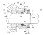
- FIG. 1 is a schematic cross-sectional view showing a use state of the mechanical seal according to Embodiment 1 of the present invention.
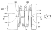
- FIG. 2 is a top view which shows the use condition of the press member based on Example 1 of this invention.
- FIG. 3 is a schematic cross-sectional view showing a use state of the mechanical seal according to Embodiment 2 of the present invention.
- FIG. 4 is a top view which shows the use condition of the press member based on Example 2 of this invention.
- FIG. 1 is a schematic cross-sectional view showing a use state of the mechanical seal according to Embodiment 1 of the present invention.
- the mechanical seal according to the present embodiment has a rotationally symmetric shape except for some members, and FIG. 1 shows a cross-sectional view of the mechanical seal cut along a plane including the central axis of the mechanical seal.
- FIG. 2 is a plan view showing a state of use of the pressing member according to the first embodiment of the present invention, showing a part of a plan view in the vicinity where the pressing member is provided in the mechanical seal.
- sectional drawing of the pressing member vicinity in FIG. 1 is corresponded to CC sectional drawing in FIG.
- the whole structure of the mechanical seal 10 which concerns on a present Example is demonstrated.
- the mechanical seal 10 plays a role of sealing an annular gap between the rotating shaft 500 and a housing 600 having an axial hole of the rotating shaft 500.
- the mechanical seal 10 seals an annular gap between the rotating shaft 500 and the housing 600 to separate the left area (A) and the right area (B) in the drawing. If the fluid to be sealed is sealed in the region (A) and the region (B) is on the air side according to the use environment, the fluid to be sealed is sealed in the region (B) and the region (A) is on the air side In some cases, the fluid to be sealed is sealed in both regions (A) and (B).
- the mechanical seal 10 includes a fixed ring 110 and a rotating ring 210.
- the fixed ring 110 is fixed relative to the housing 600, and the rotating ring 210 is configured to rotate with the rotating shaft 500.
- An annular notch 610 is provided on the front end side (the front end side on the area (B) side) of the housing 600 and on the inner peripheral surface side.
- a gasket 120 made of an elastic body is attached to the notch 610.
- the gasket 120 is composed of a cylindrical portion 121 and an inward flange portion 122.
- the gasket 120 is fitted and fixed to the notch 610 so that the outer circumferential surface of the cylindrical portion 121 is in close contact with the inner circumferential surface of the notch 610.
- the cylindrical fixing ring 110 is fixed to the inner peripheral surface of the cylindrical portion 121 in the gasket 120 by fitting.
- the fixing ring 110 is fixed to the housing 600, and the annular gap between the fixing ring 110 and the housing 600 is sealed by the gasket 120.
- the fixed ring 110 is made of a hard material such as Sic, carbon or metal.
- the end face of the fixed ring 110 on the side where the rotary ring 210 is disposed (right side in FIGS. 1 and 2) is a sliding surface with the rotary ring 210.
- the rotary ring 210 is made of a hard material such as Sic, carbon or metal.
- the rotary ring 210 is provided with an annular protrusion 211 projecting toward the fixed ring 110 side. The distal end surface of the annular protrusion 211 slides on the fixed ring 110.
- an annular notch 212 is provided on the inner circumferential surface side of the rotary ring 210.
- a seal ring 220 made of a rubber-like elastic material such as an O-ring is mounted on the inner peripheral surface of the notch 212. The seal ring 220 seals an annular gap between the rotary ring 210 and the rotary shaft 500.
- the rotating shaft 500 is provided with an annular member 510 made of metal or the like.
- the annular member 510 is fixed to the rotation shaft 500 by a fixing tool 520 such as a set screw.
- a pressing member 300 is provided between the annular member 510 and the rotary ring 210.
- the pressing member 300 is disposed concentrically with the rotation shaft 500.
- the pressing member 300 is formed of a member obtained by bending a single plate-like wire (steel material such as carbon steel or stainless steel).
- the pressing member 300 is provided at the wave spring portion 310, a pair of snap ring portions 320 and 330 respectively provided at both ends of the wave spring portion 310, and the tip end portions of the pair of snap ring portions 320 and 330.
- the locking projections 321 and 331 are formed.
- the wave spring portion 310 is formed of a portion wound in a spiral while having a wave shape. That is, the wave spring portion 310 is constituted by a spirally wound portion, and the spirally wound portion is formed to wave in the spiral direction.
- the pair of retaining ring portions 320 and 330 is configured by a flat portion that is perpendicular to the central axis of the rotating shaft 500.
- the pair of locking protrusions 321 and 331 is configured by a portion where the tip end portions of the retaining ring portions 320 and 330 are bent to the opposite side to the wave spring portion 310, respectively.
- the locking protrusion 321 of one of the pair of locking protrusions 321 and 331 is locked and fixed to the locking recess 213 provided on the rotary ring 210.
- the locking recess 213 is formed by a groove formed on the end face of the rotary ring 210.
- the groove is formed to extend from the inner circumferential surface of the rotary ring 210 to the outer circumferential surface.
- the locking recess 213 provided in the rotary ring 210 is not limited to such a groove configuration as long as the locking projection 321 is locked.
- a partially recessed hole may be formed, and the locking projection 321 may be locked in this hole.
- the locking recess may be formed by a groove which does not reach the outer peripheral surface from the inner peripheral surface of the rotary ring 210 or a groove which does not reach the inner peripheral surface from the outer peripheral surface.
- the locking recess 511 is formed by a groove formed on the end face of the annular member 510.
- the groove is formed to extend from the inner circumferential surface to the outer circumferential surface of the annular member 510.
- the locking recess 511 provided in the annular member 510 is not limited to such a groove configuration as long as the locking projection 331 is locked. For example, a partially recessed hole may be formed, and the locking projection 331 may be locked in this hole.
- the locking recess may be configured by a groove that does not reach the outer peripheral surface from the inner peripheral surface of the annular member 510 or a groove that does not reach the inner peripheral surface from the outer peripheral surface.
- the winding direction of the wave spring portion 310 of the pressing member 300 from the rotary ring 210 side (retaining ring portion 320 side) to the annular member 510 side (retaining ring portion 330 side) is the rotational direction of the rotating shaft 500 (FIG. 2). (In the direction of arrow R).
- a force for reducing the diameter acts on the wave spring portion 310, so that the rotation force is stably transmitted to the rotation ring 210.
- the pressing member 300 is a wave spring which is formed of a member obtained by bending a single plate-like wire rod and has a wave shape and is spirally wound.
- the unit 310 is provided. Therefore, in order to obtain a desired spring force, the length in the central axial direction of the pressing member 300 can be made shorter than when a coil spring is used as the pressing member. Also, in order to give the pressing member 300 the rigidity necessary to transmit the rotational force, the cross-sectional area of the wire can be made narrower than in the case of the coil spring. As described above, the pressing member 300 can be miniaturized.
- the pressing member 300 is provided with retaining rings 320 and 330 at both ends, and locking projections 321 and 331 are provided at the tips of the retaining rings 320 and 330, respectively. Therefore, in order to attach the pressing member 300, a dedicated member is not required separately, and the number of parts is not increased.
- Example 2 of this invention is shown by FIG.3 and FIG.4.
- the configuration in the case where the configuration of the pressing member is different from that of the first embodiment is shown.
- the other configurations and actions are the same as those of the first embodiment, and therefore the same components are denoted by the same reference numerals and the description thereof will be appropriately omitted.
- FIG. 3 is a schematic cross-sectional view showing a use state of the mechanical seal according to Embodiment 2 of the present invention.
- the mechanical seal according to the present embodiment has a rotationally symmetric shape except for some members, and FIG. 3 shows a cross-sectional view of the mechanical seal taken along a plane including the central axis of the mechanical seal.
- FIG. 4 is a plan view showing a state of use of the pressing member according to the second embodiment of the present invention, showing a part of a plan view in the vicinity where the pressing member is provided in the mechanical seal.
- the cross-sectional view in the vicinity of the pressing member in FIG. 3 corresponds to the CC cross-sectional view in FIG. 4.
- the whole structure of the mechanical seal 10 which concerns on a present Example is demonstrated.
- the mechanical seal 10 plays a role of sealing an annular gap between the rotating shaft 500 and a housing 600 having an axial hole of the rotating shaft 500.
- the mechanical seal 10 seals the annular gap between the rotary shaft 500 and the housing 600, and the left side in FIG.
- the area (A) is separated from the area on the right (B).
- the fixed ring 110 and the rotating ring 210 are provided.
- the fixed ring 110 is fixed relative to the housing 600, and the rotating ring 210 is configured to rotate with the rotating shaft 500.
- the fixing ring 110 and the fixing structure of the fixing ring 110 to the housing 600 are the same as those of the first embodiment, and thus the description thereof is omitted.
- the configurations of the rotary ring 210 and the seal ring 220 are also the same as those of the first embodiment, so the description thereof will be omitted.
- the annular member 510 is not provided on the rotating shaft 500 according to the present embodiment.
- the rotary shaft 500 is provided with an annular groove 501.
- a pressing member 300 is provided between the annular groove 501 and the rotary ring 210.
- the pressing member 300 is disposed concentrically with the rotation shaft 500.
- the pressing member 300 is formed of a member obtained by bending a single plate-like wire (steel material such as carbon steel or stainless steel).
- the pressing member 300 includes a wave spring portion 310, a pair of snap ring portions 320 and 340 respectively provided on both ends of the wave spring portion 310, and a locking projection provided on the tip end portion of one of the snap ring portions 320. And a unit 321.
- the wave spring portion 310 is formed of a portion wound in a spiral while having a wave shape. That is, the wave spring portion 310 is constituted by a spirally wound portion, and the spirally wound portion is formed to wave in the spiral direction.
- the pair of retaining ring portions 320 and 340 is configured by a flat portion that is perpendicular to the central axis of the rotating shaft 500.
- the other retaining ring portion 340 is smaller in diameter than the one retaining ring portion 320.
- the locking projection 321 is configured by a portion where the tip end portion of the retaining ring portion 320 is bent to the opposite side to the wave spring portion 310.
- the locking projection 321 is locked and fixed to the locking recess 213 provided in the rotary ring 210.
- the locking recess 213 is formed by a groove formed on the end face of the rotary ring 210.
- the groove is formed to extend from the inner circumferential surface of the rotary ring 210 to the outer circumferential surface.
- the locking recess 213 provided in the rotary ring 210 is not limited to such a groove configuration as long as the locking projection 321 is locked.
- a partially recessed hole may be formed, and the locking projection 321 may be locked in this hole.
- the locking recess may be formed by a groove which does not reach the outer peripheral surface from the inner peripheral surface of the rotary ring 210 or a groove which does not reach the inner peripheral surface from the outer peripheral surface.
- the other retaining ring portion 340 is fitted and fixed in an annular groove 501 provided on the rotating shaft 500. As a result, the other retaining ring portion 340 is fixed to the rotation shaft 500 and is also detented.
- the winding direction of the wave spring portion 310 of the pressing member 300 from the rotary ring 210 side (retaining ring portion 320 side) to the annular groove 501 side (retaining ring portion 340 side) is the rotational direction of the rotating shaft 500 (FIG. 4). (In the direction of arrow R).
- a force for reducing the diameter acts on the wave spring portion 310, so that the rotation force is stably transmitted to the rotation ring 210.
- the pressing member 300 is formed of a member obtained by bending a single plate-like wire rod, and is a wave spring portion wound in a spiral while having a wave shape. 310 is provided. Therefore, in order to obtain a desired spring force, the length in the central axial direction of the pressing member 300 can be made shorter than when a coil spring is used as the pressing member. Also, in order to give the pressing member 300 the rigidity necessary to transmit the rotational force, the cross-sectional area of the wire can be made narrower than in the case of the coil spring. As described above, the pressing member 300 can be miniaturized.
- the pressing member 300 is provided with snap rings 320 and 340 at both ends, and a locking projection 321 is provided at the tip of one snap ring 320, and the other snap ring 340 is It is configured to be fitted and fixed to an annular groove 501 provided on the rotating shaft 500. Therefore, in order to attach the pressing member 300, a dedicated member is not required separately, and the number of parts is not increased.
Landscapes
- Engineering & Computer Science (AREA)
- General Engineering & Computer Science (AREA)
- Mechanical Engineering (AREA)
- Mechanical Sealing (AREA)
Abstract
押圧部材の小型化が可能で、かつ部品点数も少なくて済むメカニカルシールを提供する。 押圧部材300は、一枚の板状の線材が曲げ加工された部材により構成されると共に、波形状を有しつつ螺旋状に巻かれたウエーブスプリング部310と、ウエーブスプリング部310の両端にそれぞれ設けられ、回転軸500の中心軸線に対して垂直かつ平板状の一対の止め輪部320,330と、一対の止め輪部320,330の各先端部がそれぞれウエーブスプリング部310とは反対側に折り曲げられた一対の係止突起部321,331とを備え、これら一対の係止突起部321,331のうち、一方の係止突起部321が回転環210に設けられた係止凹部213に係止固定され、かつ他方の係止突起部331が回転軸500に固定された環状部材510に設けられた係止凹部511に係止固定される。
Description
本発明は、回転軸とハウジングとの間の環状隙間を密封するメカニカルシールに関する。
メカニカルシールにおいては、回転環と固定環とが摺動した状態を維持させるために、いずれか一方を他方に向けて押圧するための押圧部材が備えられている。この押圧部材として、コイルスプリングが用いられることが多い(特許文献1参照)。また、回転環を回転軸と共に回転させるために、押圧部材として用いるコイルスプリングに対して、回転軸の回転力を回転環に伝える機能も兼備させた技術も知られている(特許文献2参照)。
しかしながら、コイルスプリングの場合には、所望のばね力を得るために、中心軸線方向の長さが長くなってしまうことがある。また、コイルスプリングに対して回転力を伝える機能を兼備させた場合には、回転力を伝えるのに必要な剛性を持たせるために、コイルスプリングの線径も一定以上長くしなければならない。これにより、コイルスプリングの線材の断面積が広くなり、コイルスプリングが大型化してしまうことがある。
本発明の目的は、押圧部材の小型化が可能で、かつ部品点数も少なくて済むメカニカルシールを提供することにある。
本発明は、上記課題を解決するために以下の手段を採用した。
すなわち、本発明のメカニカルシールは、
回転軸と、該回転軸の軸孔を有するハウジングとの間の環状隙間を密封するメカニカルシールであって、
前記ハウジングに対して固定される固定環と、
前記固定環に対して摺動すると共に、前記回転軸と共に回転する回転環と、
前記回転軸による回転力を前記回転環に伝えると共に、該回転環を前記固定環に向けて押圧する押圧部材と、
を備え、
前記押圧部材は、
一枚の板状の線材が曲げ加工された部材により構成されると共に、
波形状を有しつつ螺旋状に巻かれたウエーブスプリング部と、該ウエーブスプリング部の両端にそれぞれ設けられ、前記回転軸の中心軸線に対して垂直かつ平板状の一対の止め輪部と、該一対の止め輪部の各先端部がそれぞれ前記ウエーブスプリング部とは反対側に折り曲げられた一対の係止突起部とを備え、
これら一対の係止突起部のうち、一方の係止突起部が前記回転環に設けられた係止凹部に係止固定され、かつ他方の係止突起部が前記回転軸に固定された部材に設けられた係止凹部に係止固定されることを特徴とする。
回転軸と、該回転軸の軸孔を有するハウジングとの間の環状隙間を密封するメカニカルシールであって、
前記ハウジングに対して固定される固定環と、
前記固定環に対して摺動すると共に、前記回転軸と共に回転する回転環と、
前記回転軸による回転力を前記回転環に伝えると共に、該回転環を前記固定環に向けて押圧する押圧部材と、
を備え、
前記押圧部材は、
一枚の板状の線材が曲げ加工された部材により構成されると共に、
波形状を有しつつ螺旋状に巻かれたウエーブスプリング部と、該ウエーブスプリング部の両端にそれぞれ設けられ、前記回転軸の中心軸線に対して垂直かつ平板状の一対の止め輪部と、該一対の止め輪部の各先端部がそれぞれ前記ウエーブスプリング部とは反対側に折り曲げられた一対の係止突起部とを備え、
これら一対の係止突起部のうち、一方の係止突起部が前記回転環に設けられた係止凹部に係止固定され、かつ他方の係止突起部が前記回転軸に固定された部材に設けられた係止凹部に係止固定されることを特徴とする。
また、他の発明は、
回転軸と、該回転軸の軸孔を有するハウジングとの間の環状隙間を密封するメカニカルシールであって、
前記ハウジングに対して固定される固定環と、
前記固定環に対して摺動すると共に、前記回転軸と共に回転する回転環と、
前記回転軸による回転力を前記回転環に伝えると共に、該回転環を前記固定環に向けて押圧する押圧部材と、
を備え、
前記押圧部材は、
一枚の板状の線材が曲げ加工された部材により構成されると共に、
波形状を有しつつ螺旋状に巻かれたウエーブスプリング部と、該ウエーブスプリング部の両端にそれぞれ設けられ、前記回転軸の中心軸線に対して垂直かつ平板状の一対の止め輪部と、を備え、
前記一対の止め輪部のうちの一方の止め輪部には、先端部が前記ウエーブスプリング部とは反対側に折り曲げられた係止突起部が備えられており、前記一対の止め輪部のうちの他方の止め輪部は、前記一方の止め輪部よりも径が小さく構成されており、
前記係止突起部が前記回転環に設けられた係止凹部に係止固定され、前記他方の止め輪部が前記回転軸に設けられた環状溝に嵌合固定されることを特徴とする。
回転軸と、該回転軸の軸孔を有するハウジングとの間の環状隙間を密封するメカニカルシールであって、
前記ハウジングに対して固定される固定環と、
前記固定環に対して摺動すると共に、前記回転軸と共に回転する回転環と、
前記回転軸による回転力を前記回転環に伝えると共に、該回転環を前記固定環に向けて押圧する押圧部材と、
を備え、
前記押圧部材は、
一枚の板状の線材が曲げ加工された部材により構成されると共に、
波形状を有しつつ螺旋状に巻かれたウエーブスプリング部と、該ウエーブスプリング部の両端にそれぞれ設けられ、前記回転軸の中心軸線に対して垂直かつ平板状の一対の止め輪部と、を備え、
前記一対の止め輪部のうちの一方の止め輪部には、先端部が前記ウエーブスプリング部とは反対側に折り曲げられた係止突起部が備えられており、前記一対の止め輪部のうちの他方の止め輪部は、前記一方の止め輪部よりも径が小さく構成されており、
前記係止突起部が前記回転環に設けられた係止凹部に係止固定され、前記他方の止め輪部が前記回転軸に設けられた環状溝に嵌合固定されることを特徴とする。
これらの発明によれば、押圧部材は、一枚の板状の線材が曲げ加工された部材により構成されると共に、波形状を有しつつ螺旋状に巻かれたウエーブスプリング部を備えている。従って、所望のばね力を得るために、押圧部材における中心軸線方向の長さを、コイルスプリングを用いた場合よりも短くすることができる。また、押圧部材に対して、回転力を伝えるのに必要な剛性を持たせるために、線材の断面積を、コイルスプリングの場合よりも狭くすることができる。以上より、押圧部材の小型化を図ることができる。
また、前者の発明によれば、押圧部材は、両端にそれぞれ止め輪部が設けられ、かつ、これらの止め輪部の先端にはそれぞれ係止突起部が設けられている。そして、後者の発明によれば、押圧部材は、両端にそれぞれ止め輪部が設けられ、かつ、一方の止め輪部の先端には係止突起部が設けられており、他方の止め輪部は回転軸に設けられた環状溝に嵌合固定される構成である。従って、いずれの発明も、押圧部材を取り付けるために、別途、専用の部材を必要としないため、部品点数が増えてしまうこともない。
以上説明したように、本発明によれば、押圧部材の小型化が可能で、かつ部品点数も少なくて済む。
以下に図面を参照して、この発明を実施するための形態を、実施例に基づいて例示的に詳しく説明する。ただし、この実施例に記載されている構成部品の寸法、材質、形状、その相対配置などは、特に特定的な記載がない限りは、この発明の範囲をそれらのみに限定する趣旨のものではない。
(実施例1)
図1及び図2を参照して、本発明の実施例1に係るメカニカルシールについて説明する。図1は本発明の実施例1に係るメカニカルシールの使用状態を示す模式的断面図である。なお、本実施例に係るメカニカルシールは、一部の部材を除き、回転対称形状であり、図1においては、メカニカルシールの中心軸線を含む面でメカニカルシールを切断した断面図を示している。図2は本発明の実施例1に係る押圧部材の使用状態を示す平面図であり、メカニカルシールにおいて、押圧部材が設けられている付近の平面図の一部を示したものである。なお、図1中の押圧部材付近の断面図は、図2中のCC断面図に相当する。
図1及び図2を参照して、本発明の実施例1に係るメカニカルシールについて説明する。図1は本発明の実施例1に係るメカニカルシールの使用状態を示す模式的断面図である。なお、本実施例に係るメカニカルシールは、一部の部材を除き、回転対称形状であり、図1においては、メカニカルシールの中心軸線を含む面でメカニカルシールを切断した断面図を示している。図2は本発明の実施例1に係る押圧部材の使用状態を示す平面図であり、メカニカルシールにおいて、押圧部材が設けられている付近の平面図の一部を示したものである。なお、図1中の押圧部材付近の断面図は、図2中のCC断面図に相当する。
<メカニカルシール>
本実施例に係るメカニカルシール10の全体構成について説明する。メカニカルシール10は、回転軸500と、回転軸500の軸孔を有するハウジング600との間の環状隙間を密封する役割を担っている。図1に示すように、メカニカルシール10によって、回転軸500とハウジング600との間の環状隙間が封止されて、図中左側の領域(A)と右側の領域(B)とが隔てられる。使用環境に応じて、領域(A)に密封対象流体が封止され、領域(B)が大気側となる場合、領域(B)に密封対象流体が封止され、領域(A)が大気側となる場合の他、双方の領域(A)(B)に密封対象流体が封止される場合もある。
本実施例に係るメカニカルシール10の全体構成について説明する。メカニカルシール10は、回転軸500と、回転軸500の軸孔を有するハウジング600との間の環状隙間を密封する役割を担っている。図1に示すように、メカニカルシール10によって、回転軸500とハウジング600との間の環状隙間が封止されて、図中左側の領域(A)と右側の領域(B)とが隔てられる。使用環境に応じて、領域(A)に密封対象流体が封止され、領域(B)が大気側となる場合、領域(B)に密封対象流体が封止され、領域(A)が大気側となる場合の他、双方の領域(A)(B)に密封対象流体が封止される場合もある。
メカニカルシール10は、固定環110と回転環210とを備えている。固定環110はハウジング600に対して固定され、回転環210は回転軸500と共に回転するように構成されている。
まず、固定環110のハウジング600への固定構造について説明する。ハウジング600の先端側(領域(B)側の先端側)かつ内周面側には、環状の切欠き部610が設けられている。そして、この切欠き部610に弾性体製のガスケット120が装着されている。ガスケット120は、円筒部121と内向きフランジ部122とから構成されている。円筒部121の外周面が切欠き部610の内周面に密着するように、ガスケット120は切欠き部610に嵌合により固定されている。そして、ガスケット120における円筒部121の内周面に対して、円筒状の固定環110が嵌合により固定される。以上の構成により、固定環110がハウジング600に対して固定されると共に、固定環110とハウジング600との間の環状隙間はガスケット120によって封止される。なお、固定環110は、Sic,カーボンまたは金属などの硬質材料で構成される。この固定環110のうち回転環210が配置される側(図1,2中右側)の端面が回転環210との摺動面となる。
回転環210は、Sic,カーボンまたは金属などの硬質材料で構成される。この回転環210には、固定環110側に向かって突出する環状突出部211が設けられている。この環状突出部211の先端面が固定環110に対して摺動する。また、回転環210の内周面側には環状の切欠き部212が設けられている。この切欠き部212の内周面に対して、Oリングなどのゴム状弾性体製のシールリング220が装着される。このシールリング220によって、回転環210と回転軸500との間の環状隙間が封止されている。
回転軸500には、金属などにより構成される環状部材510が設けられている。この環状部材510は、セットスクリュなどの固定具520によって、回転軸500に固定されている。そして、この環状部材510と回転環210との間に、押圧部材300が設けられている。押圧部材300は回転軸500と同心的に配置される。この押圧部材300によって、回転軸500による回転力が回転環210に伝えられ、かつ回転環210が固定環110に向けて押圧される。これにより、回転環210と固定環110とが密着した状態を維持させることができる。
<押圧部材>
押圧部材300に関連する構成について、より詳細に説明する。押圧部材300は、一枚の板状の線材(炭素鋼やステンレス鋼などの鋼材)が曲げ加工された部材により構成される。そして、押圧部材300は、ウエーブスプリング部310と、ウエーブスプリング部310の両端にそれぞれ設けられた一対の止め輪部320,330と、これら一対の止め輪部320,330の各先端部に設けられた係止突起部321,331とから構成される。
押圧部材300に関連する構成について、より詳細に説明する。押圧部材300は、一枚の板状の線材(炭素鋼やステンレス鋼などの鋼材)が曲げ加工された部材により構成される。そして、押圧部材300は、ウエーブスプリング部310と、ウエーブスプリング部310の両端にそれぞれ設けられた一対の止め輪部320,330と、これら一対の止め輪部320,330の各先端部に設けられた係止突起部321,331とから構成される。
ウエーブスプリング部310は、波形状を有しつつ螺旋状に巻かれた部位により構成されている。つまり、ウエーブスプリング部310は、螺旋状に巻かれた部位により構成され、かつ螺旋状の巻かれた部位は、螺旋方向に対して波を打つように形成されている。一対の止め輪部320,330は、回転軸500の中心軸線に対して垂直かつ平板状の部位により構成されている。一対の係止突起部321,331は、止め輪部320,330の各先端部がそれぞれウエーブスプリング部310とは反対側に折り曲げられた部位により構成されている。
そして、一対の係止突起部321,331のうちの一方の係止突起部321は、回転環210に設けられた係止凹部213に係止固定されている。なお、係止凹部213は、回転環210の端面に形成された溝によって構成される。この溝は、回転環210の内周面から外周面に至るように形成されている。ただし、回転環210に設ける係止凹部213は、係止突起部321が係止されさえすれば、このような溝による構成に限定されることはない。例えば、部分的に凹んだ穴を形成し、この穴に係止突起部321を係止させても良い。また、回転環210の内周面から外周面には至らないような溝や、外周面から内周面には至らないような溝によって係止凹部を構成することもできる。以上の構成により、回転環210に対して係止突起部321の廻り止めがなされる。
また、一対の係止突起部321,331のうちの他方の係止突起部331は、回転軸500に固定された環状部材510に設けられた係止凹部511に係止固定されている。なお、係止凹部511は、環状部材510の端面に形成された溝によって構成される。この溝は、環状部材510の内周面から外周面に至るように形成されている。ただし、環状部材510に設ける係止凹部511は、係止突起部331が係止されさえすれば、このような溝による構成に限定されることはない。例えば、部分的に凹んだ穴を形成し、この穴に係止突起部331を係止させても良い。また、環状部材510の内周面から外周面には至らないような溝や、外周面から内周面には至らないような溝によって係止凹部を構成することもできる。以上の構成により、環状部材510に対して係止突起部331の廻り止めがなされる。
ここで、押圧部材300におけるウエーブスプリング部310の回転環210側(止め輪部320側)から環状部材510側(止め輪部330側)への巻き方向は、回転軸500の回転方向(図2中、矢印R方向)に一致するように構成されている。これにより、回転軸500が回転する際に、ウエーブスプリング部310に対して縮径させる力が作用するため、回転環210に対して、回転力が安定的に伝えられる。
<本実施例に係るメカニカルシールの優れた点>
本実施例に係るメカニカルシール10によれば、押圧部材300は、一枚の板状の線材が曲げ加工された部材により構成されると共に、波形状を有しつつ螺旋状に巻かれたウエーブスプリング部310を備えている。従って、所望のばね力を得るために、押圧部材300における中心軸線方向の長さを、押圧部材としてコイルスプリングを用いた場合よりも短くすることができる。また、押圧部材300に対して、回転力を伝えるのに必要な剛性を持たせるために、線材の断面積を、コイルスプリングの場合よりも狭くすることができる。以上より、押圧部材300の小型化を図ることができる。
本実施例に係るメカニカルシール10によれば、押圧部材300は、一枚の板状の線材が曲げ加工された部材により構成されると共に、波形状を有しつつ螺旋状に巻かれたウエーブスプリング部310を備えている。従って、所望のばね力を得るために、押圧部材300における中心軸線方向の長さを、押圧部材としてコイルスプリングを用いた場合よりも短くすることができる。また、押圧部材300に対して、回転力を伝えるのに必要な剛性を持たせるために、線材の断面積を、コイルスプリングの場合よりも狭くすることができる。以上より、押圧部材300の小型化を図ることができる。
また、押圧部材300は、両端にそれぞれ止め輪部320,330が設けられ、かつ、これらの止め輪部320,330の先端にはそれぞれ係止突起部321,331が設けられている。従って、押圧部材300を取り付けるために、別途、専用の部材を必要としないため、部品点数が増えてしまうこともない。
(実施例2)
図3及び図4には、本発明の実施例2が示されている。本実施例においては、押圧部材の構成が、上記実施例1とは異なる場合の構成を示す。その他の構成および作用については実施例1と同一なので、同一の構成部分については同一の符号を付して、その説明は適宜省略する。
図3及び図4には、本発明の実施例2が示されている。本実施例においては、押圧部材の構成が、上記実施例1とは異なる場合の構成を示す。その他の構成および作用については実施例1と同一なので、同一の構成部分については同一の符号を付して、その説明は適宜省略する。
図3は本発明の実施例2に係るメカニカルシールの使用状態を示す模式的断面図である。なお、本実施例に係るメカニカルシールは、一部の部材を除き、回転対称形状であり、図3においては、メカニカルシールの中心軸線を含む面でメカニカルシールを切断した断面図を示している。図4は本発明の実施例2に係る押圧部材の使用状態を示す平面図であり、メカニカルシールにおいて、押圧部材が設けられている付近の平面図の一部を示したものである。なお、図3中の押圧部材付近の断面図は、図4中のCC断面図に相当する。
<メカニカルシール>
本実施例に係るメカニカルシール10の全体構成について説明する。メカニカルシール10は、回転軸500と、回転軸500の軸孔を有するハウジング600との間の環状隙間を密封する役割を担っている。図3に示すように、本実施例においても、上記実施例1の場合と同様に、メカニカルシール10によって、回転軸500とハウジング600との間の環状隙間が封止されて、図中左側の領域(A)と右側の領域(B)とが隔てられる。
本実施例に係るメカニカルシール10の全体構成について説明する。メカニカルシール10は、回転軸500と、回転軸500の軸孔を有するハウジング600との間の環状隙間を密封する役割を担っている。図3に示すように、本実施例においても、上記実施例1の場合と同様に、メカニカルシール10によって、回転軸500とハウジング600との間の環状隙間が封止されて、図中左側の領域(A)と右側の領域(B)とが隔てられる。
本実施例に係るメカニカルシール10においても、実施例1の場合と同様に、固定環110と回転環210とを備えている。固定環110はハウジング600に対して固定され、回転環210は回転軸500と共に回転するように構成されている。固定環110、及び固定環110のハウジング600への固定構造については、上記実施例1の場合と同一であるので、その説明は省略する。また、回転環210とシールリング220の構成についても、上記実施例1の場合と同一であるので、その説明は省略する。
本実施例に係る回転軸500には、上記実施例1の場合とは異なり、環状部材510は設けられていない。その代わりに、回転軸500には、環状溝501が設けられている。そして、この環状溝501と回転環210との間に、押圧部材300が設けられている。押圧部材300は回転軸500と同心的に配置される。この押圧部材300によって、回転軸500による回転力が回転環210に伝えられ、かつ回転環210が固定環110に向けて押圧される。これにより、回転環210と固定環110とが密着した状態を維持させることができる。
<押圧部材>
押圧部材300に関連する構成について、より詳細に説明する。押圧部材300は、一枚の板状の線材(炭素鋼やステンレス鋼などの鋼材)が曲げ加工された部材により構成される。そして、押圧部材300は、ウエーブスプリング部310と、ウエーブスプリング部310の両端にそれぞれ設けられた一対の止め輪部320,340と、一方の止め輪部320の先端部に設けられた係止突起部321とから構成される。
押圧部材300に関連する構成について、より詳細に説明する。押圧部材300は、一枚の板状の線材(炭素鋼やステンレス鋼などの鋼材)が曲げ加工された部材により構成される。そして、押圧部材300は、ウエーブスプリング部310と、ウエーブスプリング部310の両端にそれぞれ設けられた一対の止め輪部320,340と、一方の止め輪部320の先端部に設けられた係止突起部321とから構成される。
ウエーブスプリング部310は、波形状を有しつつ螺旋状に巻かれた部位により構成されている。つまり、ウエーブスプリング部310は、螺旋状に巻かれた部位により構成され、かつ螺旋状の巻かれた部位は、螺旋方向に対して波を打つように形成されている。一対の止め輪部320,340は、回転軸500の中心軸線に対して垂直かつ平板状の部位により構成されている。ここで、他方の止め輪部340は、一方の止め輪部320よりも径が小さい。また、係止突起部321は、止め輪部320の先端部がウエーブスプリング部310とは反対側に折り曲げられた部位により構成されている。
そして、係止突起部321は、回転環210に設けられた係止凹部213に係止固定されている。なお、係止凹部213は、回転環210の端面に形成された溝によって構成される。この溝は、回転環210の内周面から外周面に至るように形成されている。ただし、回転環210に設ける係止凹部213は、係止突起部321が係止されさえすれば、このような溝による構成に限定されることはない。例えば、部分的に凹んだ穴を形成し、この穴に係止突起部321を係止させても良い。また、回転環210の内周面から外周面には至らないような溝や、外周面から内周面には至らないような溝によって係止凹部を構成することもできる。以上の構成により、回転環210に対して係止突起部321の廻り止めがなされる。
また、他方の止め輪部340は、回転軸500に設けられた環状溝501に嵌合固定されている。これにより、回転軸500に対して、他方の止め輪部340は固定されて、廻り止めもなされる。
ここで、押圧部材300におけるウエーブスプリング部310の回転環210側(止め輪部320側)から環状溝501側(止め輪部340側)への巻き方向は、回転軸500の回転方向(図4中、矢印R方向)に一致するように構成されている。これにより、回転軸500が回転する際に、ウエーブスプリング部310に対して縮径させる力が作用するため、回転環210に対して、回転力が安定的に伝えられる。
<本実施例に係るメカニカルシールの優れた点>
本実施例に係るメカニカルシール10においても、押圧部材300は、一枚の板状の線材が曲げ加工された部材により構成されると共に、波形状を有しつつ螺旋状に巻かれたウエーブスプリング部310を備えている。従って、所望のばね力を得るために、押圧部材300における中心軸線方向の長さを、押圧部材としてコイルスプリングを用いた場合よりも短くすることができる。また、押圧部材300に対して、回転力を伝えるのに必要な剛性を持たせるために、線材の断面積を、コイルスプリングの場合よりも狭くすることができる。以上より、押圧部材300の小型化を図ることができる。
本実施例に係るメカニカルシール10においても、押圧部材300は、一枚の板状の線材が曲げ加工された部材により構成されると共に、波形状を有しつつ螺旋状に巻かれたウエーブスプリング部310を備えている。従って、所望のばね力を得るために、押圧部材300における中心軸線方向の長さを、押圧部材としてコイルスプリングを用いた場合よりも短くすることができる。また、押圧部材300に対して、回転力を伝えるのに必要な剛性を持たせるために、線材の断面積を、コイルスプリングの場合よりも狭くすることができる。以上より、押圧部材300の小型化を図ることができる。
また、押圧部材300は、両端にそれぞれ止め輪部320,340が設けられ、かつ、一方の止め輪部320の先端には係止突起部321が設けられており、他方の止め輪部340は回転軸500に設けられた環状溝501に嵌合固定される構成である。従って、押圧部材300を取り付けるために、別途、専用の部材を必要としないため、部品点数が増えてしまうこともない。
10 メカニカルシール
110 固定環
120 ガスケット
121 円筒部
122 内向きフランジ部
210 回転環
211 環状突出部
212 切欠き部
213 係止凹部
220 シールリング
300 押圧部材
310 ウエーブスプリング部
320,330,340 止め輪部
321,331 係止突起部
500 回転軸
501 環状溝
510 環状部材
511 係止凹部
520 固定具
600 ハウジング
610 切欠き部
110 固定環
120 ガスケット
121 円筒部
122 内向きフランジ部
210 回転環
211 環状突出部
212 切欠き部
213 係止凹部
220 シールリング
300 押圧部材
310 ウエーブスプリング部
320,330,340 止め輪部
321,331 係止突起部
500 回転軸
501 環状溝
510 環状部材
511 係止凹部
520 固定具
600 ハウジング
610 切欠き部
Claims (2)
- 回転軸と、該回転軸の軸孔を有するハウジングとの間の環状隙間を密封するメカニカルシールであって、
前記ハウジングに対して固定される固定環と、
前記固定環に対して摺動すると共に、前記回転軸と共に回転する回転環と、
前記回転軸による回転力を前記回転環に伝えると共に、該回転環を前記固定環に向けて押圧する押圧部材と、
を備え、
前記押圧部材は、
一枚の板状の線材が曲げ加工された部材により構成されると共に、
波形状を有しつつ螺旋状に巻かれたウエーブスプリング部と、該ウエーブスプリング部の両端にそれぞれ設けられ、前記回転軸の中心軸線に対して垂直かつ平板状の一対の止め輪部と、該一対の止め輪部の各先端部がそれぞれ前記ウエーブスプリング部とは反対側に折り曲げられた一対の係止突起部とを備え、
これら一対の係止突起部のうち、一方の係止突起部が前記回転環に設けられた係止凹部に係止固定され、かつ他方の係止突起部が前記回転軸に固定された部材に設けられた係止凹部に係止固定されることを特徴とするメカニカルシール。 - 回転軸と、該回転軸の軸孔を有するハウジングとの間の環状隙間を密封するメカニカルシールであって、
前記ハウジングに対して固定される固定環と、
前記固定環に対して摺動すると共に、前記回転軸と共に回転する回転環と、
前記回転軸による回転力を前記回転環に伝えると共に、該回転環を前記固定環に向けて押圧する押圧部材と、
を備え、
前記押圧部材は、
一枚の板状の線材が曲げ加工された部材により構成されると共に、
波形状を有しつつ螺旋状に巻かれたウエーブスプリング部と、該ウエーブスプリング部の両端にそれぞれ設けられ、前記回転軸の中心軸線に対して垂直かつ平板状の一対の止め輪部と、を備え、
前記一対の止め輪部のうちの一方の止め輪部には、先端部が前記ウエーブスプリング部とは反対側に折り曲げられた係止突起部が備えられており、前記一対の止め輪部のうちの他方の止め輪部は、前記一方の止め輪部よりも径が小さく構成されており、
前記係止突起部が前記回転環に設けられた係止凹部に係止固定され、前記他方の止め輪部が前記回転軸に設けられた環状溝に嵌合固定されることを特徴とするメカニカルシール。
Priority Applications (1)
| Application Number | Priority Date | Filing Date | Title |
|---|---|---|---|
| JP2019532857A JP6991690B2 (ja) | 2017-07-26 | 2018-07-26 | メカニカルシール |
Applications Claiming Priority (2)
| Application Number | Priority Date | Filing Date | Title |
|---|---|---|---|
| JP2017-144414 | 2017-07-26 | ||
| JP2017144414 | 2017-07-26 |
Publications (1)
| Publication Number | Publication Date |
|---|---|
| WO2019022191A1 true WO2019022191A1 (ja) | 2019-01-31 |
Family
ID=65039747
Family Applications (1)
| Application Number | Title | Priority Date | Filing Date |
|---|---|---|---|
| PCT/JP2018/028053 Ceased WO2019022191A1 (ja) | 2017-07-26 | 2018-07-26 | メカニカルシール |
Country Status (2)
| Country | Link |
|---|---|
| JP (1) | JP6991690B2 (ja) |
| WO (1) | WO2019022191A1 (ja) |
Citations (3)
| Publication number | Priority date | Publication date | Assignee | Title |
|---|---|---|---|---|
| JPS53145050U (ja) * | 1977-04-20 | 1978-11-15 | ||
| JPS603365U (ja) * | 1983-06-22 | 1985-01-11 | 炭研精工株式会社 | メカニカルシ−ル |
| JP2006105234A (ja) * | 2004-10-04 | 2006-04-20 | Yamatake Corp | 固定具および組立構造体 |
-
2018
- 2018-07-26 JP JP2019532857A patent/JP6991690B2/ja active Active
- 2018-07-26 WO PCT/JP2018/028053 patent/WO2019022191A1/ja not_active Ceased
Patent Citations (3)
| Publication number | Priority date | Publication date | Assignee | Title |
|---|---|---|---|---|
| JPS53145050U (ja) * | 1977-04-20 | 1978-11-15 | ||
| JPS603365U (ja) * | 1983-06-22 | 1985-01-11 | 炭研精工株式会社 | メカニカルシ−ル |
| JP2006105234A (ja) * | 2004-10-04 | 2006-04-20 | Yamatake Corp | 固定具および組立構造体 |
Also Published As
| Publication number | Publication date |
|---|---|
| JP6991690B2 (ja) | 2022-01-12 |
| JPWO2019022191A1 (ja) | 2020-05-28 |
Similar Documents
| Publication | Publication Date | Title |
|---|---|---|
| JP2008281192A (ja) | シールリング | |
| JP6385347B2 (ja) | メカニカルシール | |
| WO2018037918A1 (ja) | 密封装置 | |
| JP6328658B2 (ja) | メカニカルシール | |
| WO2014054472A1 (ja) | 密封装置 | |
| JP6942431B2 (ja) | メカニカルシール | |
| JPWO2018012330A1 (ja) | メカニカルシール | |
| WO2019022191A1 (ja) | メカニカルシール | |
| WO2021002140A1 (ja) | ボールバルブ | |
| JP7046928B2 (ja) | メカニカルシール | |
| JP6839563B2 (ja) | 密封装置 | |
| JP5534733B2 (ja) | 自在継手用ブーツ | |
| JP6934731B2 (ja) | 直動機構 | |
| JP6240038B2 (ja) | メカニカルシール | |
| JP2010249219A (ja) | シールリング | |
| WO2015151310A1 (ja) | 絞り弁 | |
| JP6422302B2 (ja) | 直線駆動装置 | |
| JP5577212B2 (ja) | 軸封装置 | |
| JP5695531B2 (ja) | 端面接触形メカニカルシール | |
| JPH11141688A (ja) | 密封装置 | |
| JP6524763B2 (ja) | ボールねじ機構及びアクチュエータ | |
| JP2005344858A (ja) | トルクリミッタ | |
| JP5849647B2 (ja) | 密封装置 | |
| JPWO2019038983A1 (ja) | 減速機 | |
| US20240200660A1 (en) | Sealing device |
Legal Events
| Date | Code | Title | Description |
|---|---|---|---|
| 121 | Ep: the epo has been informed by wipo that ep was designated in this application |
Ref document number: 18837934 Country of ref document: EP Kind code of ref document: A1 |
|
| ENP | Entry into the national phase |
Ref document number: 2019532857 Country of ref document: JP Kind code of ref document: A |
|
| NENP | Non-entry into the national phase |
Ref country code: DE |
|
| 122 | Ep: pct application non-entry in european phase |
Ref document number: 18837934 Country of ref document: EP Kind code of ref document: A1 |