WO2019022024A1 - 偏光板の製造方法及び表示装置の製造方法 - Google Patents
偏光板の製造方法及び表示装置の製造方法 Download PDFInfo
- Publication number
- WO2019022024A1 WO2019022024A1 PCT/JP2018/027549 JP2018027549W WO2019022024A1 WO 2019022024 A1 WO2019022024 A1 WO 2019022024A1 JP 2018027549 W JP2018027549 W JP 2018027549W WO 2019022024 A1 WO2019022024 A1 WO 2019022024A1
- Authority
- WO
- WIPO (PCT)
- Prior art keywords
- polarizing plate
- film
- stretching
- material film
- laminate
- Prior art date
Links
- 238000004519 manufacturing process Methods 0.000 title claims abstract description 192
- 239000000463 material Substances 0.000 claims abstract description 216
- 238000000034 method Methods 0.000 claims description 99
- 239000004372 Polyvinyl alcohol Substances 0.000 claims description 51
- 239000010410 layer Substances 0.000 claims description 51
- 229920002451 polyvinyl alcohol Polymers 0.000 claims description 51
- 229920000642 polymer Polymers 0.000 claims description 45
- 239000004014 plasticizer Substances 0.000 claims description 36
- 239000000853 adhesive Substances 0.000 claims description 30
- 230000001070 adhesive effect Effects 0.000 claims description 29
- 239000012790 adhesive layer Substances 0.000 claims description 29
- 239000011347 resin Substances 0.000 claims description 29
- 229920005989 resin Polymers 0.000 claims description 29
- -1 aromatic vinyl compound Chemical class 0.000 claims description 24
- 239000004973 liquid crystal related substance Substances 0.000 claims description 23
- 230000001681 protective effect Effects 0.000 claims description 20
- 150000001925 cycloalkenes Chemical class 0.000 claims description 19
- 150000004678 hydrides Chemical class 0.000 claims description 19
- 238000004043 dyeing Methods 0.000 claims description 17
- 229920001400 block copolymer Polymers 0.000 claims description 15
- 239000000126 substance Substances 0.000 claims description 14
- 229920001577 copolymer Polymers 0.000 claims description 13
- 229920000089 Cyclic olefin copolymer Polymers 0.000 claims description 11
- 239000000178 monomer Substances 0.000 claims description 11
- 229920002554 vinyl polymer Polymers 0.000 claims description 11
- 150000002148 esters Chemical group 0.000 claims description 10
- 239000000203 mixture Substances 0.000 claims description 9
- JFNLZVQOOSMTJK-KNVOCYPGSA-N norbornene Chemical compound C1[C@@H]2CC[C@H]1C=C2 JFNLZVQOOSMTJK-KNVOCYPGSA-N 0.000 claims description 9
- 239000004925 Acrylic resin Substances 0.000 claims description 8
- 229920000178 Acrylic resin Polymers 0.000 claims description 8
- 239000002994 raw material Substances 0.000 claims description 8
- 150000001338 aliphatic hydrocarbons Chemical class 0.000 claims description 6
- 239000004711 α-olefin Substances 0.000 claims description 6
- 238000007142 ring opening reaction Methods 0.000 claims description 4
- 229920001225 polyester resin Polymers 0.000 claims description 3
- 239000004645 polyester resin Substances 0.000 claims description 3
- 229920005672 polyolefin resin Polymers 0.000 claims description 3
- 238000010186 staining Methods 0.000 claims description 3
- 239000010408 film Substances 0.000 description 441
- 239000000758 substrate Substances 0.000 description 62
- NLKNQRATVPKPDG-UHFFFAOYSA-M potassium iodide Chemical compound [K+].[I-] NLKNQRATVPKPDG-UHFFFAOYSA-M 0.000 description 24
- 238000011282 treatment Methods 0.000 description 23
- 238000005401 electroluminescence Methods 0.000 description 22
- 238000011156 evaluation Methods 0.000 description 15
- 230000010287 polarization Effects 0.000 description 12
- KGBXLFKZBHKPEV-UHFFFAOYSA-N boric acid Chemical compound OB(O)O KGBXLFKZBHKPEV-UHFFFAOYSA-N 0.000 description 11
- 239000004327 boric acid Substances 0.000 description 11
- 238000012545 processing Methods 0.000 description 9
- 239000000243 solution Substances 0.000 description 9
- 239000004820 Pressure-sensitive adhesive Substances 0.000 description 7
- 230000000052 comparative effect Effects 0.000 description 7
- 239000000975 dye Substances 0.000 description 7
- 238000006116 polymerization reaction Methods 0.000 description 7
- 238000007127 saponification reaction Methods 0.000 description 7
- PEDCQBHIVMGVHV-UHFFFAOYSA-N Glycerine Chemical compound OCC(O)CO PEDCQBHIVMGVHV-UHFFFAOYSA-N 0.000 description 6
- 239000007864 aqueous solution Substances 0.000 description 6
- 230000000694 effects Effects 0.000 description 6
- 238000001125 extrusion Methods 0.000 description 6
- 238000010030 laminating Methods 0.000 description 6
- 238000000465 moulding Methods 0.000 description 6
- 239000012192 staining solution Substances 0.000 description 6
- 150000005846 sugar alcohols Polymers 0.000 description 6
- LYCAIKOWRPUZTN-UHFFFAOYSA-N Ethylene glycol Chemical compound OCCO LYCAIKOWRPUZTN-UHFFFAOYSA-N 0.000 description 5
- 238000001035 drying Methods 0.000 description 5
- PNDPGZBMCMUPRI-UHFFFAOYSA-N iodine Chemical compound II PNDPGZBMCMUPRI-UHFFFAOYSA-N 0.000 description 5
- 238000004804 winding Methods 0.000 description 5
- PPBRXRYQALVLMV-UHFFFAOYSA-N Styrene Natural products C=CC1=CC=CC=C1 PPBRXRYQALVLMV-UHFFFAOYSA-N 0.000 description 4
- 238000005984 hydrogenation reaction Methods 0.000 description 4
- 238000005259 measurement Methods 0.000 description 4
- 239000000155 melt Substances 0.000 description 4
- 229920000139 polyethylene terephthalate Polymers 0.000 description 4
- 239000005020 polyethylene terephthalate Substances 0.000 description 4
- 239000011342 resin composition Substances 0.000 description 4
- 239000002904 solvent Substances 0.000 description 4
- 238000002834 transmittance Methods 0.000 description 4
- 229920002367 Polyisobutene Polymers 0.000 description 3
- 239000002253 acid Substances 0.000 description 3
- 229910000147 aluminium phosphate Inorganic materials 0.000 description 3
- 239000003963 antioxidant agent Substances 0.000 description 3
- 150000001733 carboxylic acid esters Chemical class 0.000 description 3
- 239000003795 chemical substances by application Substances 0.000 description 3
- 150000001875 compounds Chemical class 0.000 description 3
- 235000011187 glycerol Nutrition 0.000 description 3
- 239000012943 hotmelt Substances 0.000 description 3
- 238000002844 melting Methods 0.000 description 3
- 230000008018 melting Effects 0.000 description 3
- NBIIXXVUZAFLBC-UHFFFAOYSA-N phosphoric acid Substances OP(O)(O)=O NBIIXXVUZAFLBC-UHFFFAOYSA-N 0.000 description 3
- XLYOFNOQVPJJNP-UHFFFAOYSA-N water Substances O XLYOFNOQVPJJNP-UHFFFAOYSA-N 0.000 description 3
- SZNYYWIUQFZLLT-UHFFFAOYSA-N 2-methyl-1-(2-methylpropoxy)propane Chemical compound CC(C)COCC(C)C SZNYYWIUQFZLLT-UHFFFAOYSA-N 0.000 description 2
- 229920008790 Amorphous Polyethylene terephthalate Polymers 0.000 description 2
- VGGSQFUCUMXWEO-UHFFFAOYSA-N Ethene Chemical compound C=C VGGSQFUCUMXWEO-UHFFFAOYSA-N 0.000 description 2
- 239000005977 Ethylene Substances 0.000 description 2
- WOBHKFSMXKNTIM-UHFFFAOYSA-N Hydroxyethyl methacrylate Chemical compound CC(=C)C(=O)OCCO WOBHKFSMXKNTIM-UHFFFAOYSA-N 0.000 description 2
- DKNPRRRKHAEUMW-UHFFFAOYSA-N Iodine aqueous Chemical compound [K+].I[I-]I DKNPRRRKHAEUMW-UHFFFAOYSA-N 0.000 description 2
- RRHGJUQNOFWUDK-UHFFFAOYSA-N Isoprene Chemical compound CC(=C)C=C RRHGJUQNOFWUDK-UHFFFAOYSA-N 0.000 description 2
- BAPJBEWLBFYGME-UHFFFAOYSA-N Methyl acrylate Chemical compound COC(=O)C=C BAPJBEWLBFYGME-UHFFFAOYSA-N 0.000 description 2
- VVQNEPGJFQJSBK-UHFFFAOYSA-N Methyl methacrylate Chemical compound COC(=O)C(C)=C VVQNEPGJFQJSBK-UHFFFAOYSA-N 0.000 description 2
- 239000004793 Polystyrene Substances 0.000 description 2
- UFUQRRYHIHJMPB-DUCFOALUSA-L Sirius red 4B Chemical compound [Na+].[Na+].OS(=O)(=O)c1cc2cc(NC(=O)c3ccccc3)ccc2c([O-])c1\N=N\c1ccc(cc1)\N=N\c1ccc(cc1)S([O-])(=O)=O UFUQRRYHIHJMPB-DUCFOALUSA-L 0.000 description 2
- PMZURENOXWZQFD-UHFFFAOYSA-L Sodium Sulfate Chemical compound [Na+].[Na+].[O-]S([O-])(=O)=O PMZURENOXWZQFD-UHFFFAOYSA-L 0.000 description 2
- ZIJKGAXBCRWEOL-SAXBRCJISA-N Sucrose octaacetate Chemical compound CC(=O)O[C@H]1[C@H](OC(C)=O)[C@@H](COC(=O)C)O[C@@]1(COC(C)=O)O[C@@H]1[C@H](OC(C)=O)[C@@H](OC(C)=O)[C@H](OC(C)=O)[C@@H](COC(C)=O)O1 ZIJKGAXBCRWEOL-SAXBRCJISA-N 0.000 description 2
- XTXRWKRVRITETP-UHFFFAOYSA-N Vinyl acetate Chemical compound CC(=O)OC=C XTXRWKRVRITETP-UHFFFAOYSA-N 0.000 description 2
- 239000001344 [(2S,3S,4R,5R)-4-acetyloxy-2,5-bis(acetyloxymethyl)-2-[(2R,3R,4S,5R,6R)-3,4,5-triacetyloxy-6-(acetyloxymethyl)oxan-2-yl]oxyoxolan-3-yl] acetate Substances 0.000 description 2
- 238000004458 analytical method Methods 0.000 description 2
- 230000003078 antioxidant effect Effects 0.000 description 2
- 125000003118 aryl group Chemical group 0.000 description 2
- 238000005452 bending Methods 0.000 description 2
- CREMABGTGYGIQB-UHFFFAOYSA-N carbon carbon Chemical compound C.C CREMABGTGYGIQB-UHFFFAOYSA-N 0.000 description 2
- 239000011203 carbon fibre reinforced carbon Substances 0.000 description 2
- 150000001732 carboxylic acid derivatives Chemical class 0.000 description 2
- 239000011248 coating agent Substances 0.000 description 2
- 238000000576 coating method Methods 0.000 description 2
- 239000003086 colorant Substances 0.000 description 2
- 238000013329 compounding Methods 0.000 description 2
- 238000003851 corona treatment Methods 0.000 description 2
- 210000002858 crystal cell Anatomy 0.000 description 2
- 239000007789 gas Substances 0.000 description 2
- 230000009477 glass transition Effects 0.000 description 2
- 230000001771 impaired effect Effects 0.000 description 2
- QQVIHTHCMHWDBS-UHFFFAOYSA-N isophthalic acid Chemical compound OC(=O)C1=CC=CC(C(O)=O)=C1 QQVIHTHCMHWDBS-UHFFFAOYSA-N 0.000 description 2
- 239000000314 lubricant Substances 0.000 description 2
- 150000003014 phosphoric acid esters Chemical class 0.000 description 2
- 229920000058 polyacrylate Polymers 0.000 description 2
- 229920001083 polybutene Polymers 0.000 description 2
- 229920000728 polyester Polymers 0.000 description 2
- 229920000098 polyolefin Polymers 0.000 description 2
- 229920002223 polystyrene Polymers 0.000 description 2
- 238000000425 proton nuclear magnetic resonance spectrum Methods 0.000 description 2
- 235000019832 sodium triphosphate Nutrition 0.000 description 2
- 229940013883 sucrose octaacetate Drugs 0.000 description 2
- 229940124543 ultraviolet light absorber Drugs 0.000 description 2
- 230000000007 visual effect Effects 0.000 description 2
- 239000002699 waste material Substances 0.000 description 2
- KWKAKUADMBZCLK-UHFFFAOYSA-N 1-octene Chemical compound CCCCCCC=C KWKAKUADMBZCLK-UHFFFAOYSA-N 0.000 description 1
- XLLXMBCBJGATSP-UHFFFAOYSA-N 2-phenylethenol Chemical compound OC=CC1=CC=CC=C1 XLLXMBCBJGATSP-UHFFFAOYSA-N 0.000 description 1
- AKIVKIDZMLQJCH-KWOGCLBWSA-N 324v957sp6 Chemical compound C([C@@]1(O[C@@H]2[C@@H]([C@@H](OC(=O)C=3C=CC=CC=3)[C@H](OC(=O)C=3C=CC=CC=3)[C@@H](COC(=O)C=3C=CC=CC=3)O2)OC(=O)C=2C=CC=CC=2)O[C@@H]([C@H]([C@@H]1OC(=O)C=1C=CC=CC=1)OC(=O)C=1C=CC=CC=1)COC(=O)C=1C=CC=CC=1)OC(=O)C1=CC=CC=C1 AKIVKIDZMLQJCH-KWOGCLBWSA-N 0.000 description 1
- WSSSPWUEQFSQQG-UHFFFAOYSA-N 4-methyl-1-pentene Chemical compound CC(C)CC=C WSSSPWUEQFSQQG-UHFFFAOYSA-N 0.000 description 1
- ZCYVEMRRCGMTRW-UHFFFAOYSA-N 7553-56-2 Chemical compound [I] ZCYVEMRRCGMTRW-UHFFFAOYSA-N 0.000 description 1
- 239000004215 Carbon black (E152) Substances 0.000 description 1
- JOYRKODLDBILNP-UHFFFAOYSA-N Ethyl urethane Chemical compound CCOC(N)=O JOYRKODLDBILNP-UHFFFAOYSA-N 0.000 description 1
- UFHFLCQGNIYNRP-UHFFFAOYSA-N Hydrogen Chemical compound [H][H] UFHFLCQGNIYNRP-UHFFFAOYSA-N 0.000 description 1
- 229910019142 PO4 Inorganic materials 0.000 description 1
- 229920003171 Poly (ethylene oxide) Polymers 0.000 description 1
- 239000004952 Polyamide Substances 0.000 description 1
- 229920002396 Polyurea Polymers 0.000 description 1
- XBDQKXXYIPTUBI-UHFFFAOYSA-M Propionate Chemical compound CCC([O-])=O XBDQKXXYIPTUBI-UHFFFAOYSA-M 0.000 description 1
- 229910000831 Steel Inorganic materials 0.000 description 1
- YSMRWXYRXBRSND-UHFFFAOYSA-N TOTP Chemical compound CC1=CC=CC=C1OP(=O)(OC=1C(=CC=CC=1)C)OC1=CC=CC=C1C YSMRWXYRXBRSND-UHFFFAOYSA-N 0.000 description 1
- ZJCCRDAZUWHFQH-UHFFFAOYSA-N Trimethylolpropane Chemical compound CCC(CO)(CO)CO ZJCCRDAZUWHFQH-UHFFFAOYSA-N 0.000 description 1
- 239000001083 [(2R,3R,4S,5R)-1,2,4,5-tetraacetyloxy-6-oxohexan-3-yl] acetate Substances 0.000 description 1
- BJOZQUKWPHOFOP-PTODGXCASA-N [(2r,3r,4s,5r)-2,3,4,5-tetra(butanoyloxy)-6-oxohexyl] butanoate Chemical compound CCCC(=O)OC[C@@H](OC(=O)CCC)[C@@H](OC(=O)CCC)[C@H](OC(=O)CCC)[C@@H](OC(=O)CCC)C=O BJOZQUKWPHOFOP-PTODGXCASA-N 0.000 description 1
- UAOKXEHOENRFMP-ZJIFWQFVSA-N [(2r,3r,4s,5r)-2,3,4,5-tetraacetyloxy-6-oxohexyl] acetate Chemical compound CC(=O)OC[C@@H](OC(C)=O)[C@@H](OC(C)=O)[C@H](OC(C)=O)[C@@H](OC(C)=O)C=O UAOKXEHOENRFMP-ZJIFWQFVSA-N 0.000 description 1
- MSTNTJIQKFGIHL-OCYQJKLISA-N [(2r,3r,4s,5r)-6-oxo-2,3,4,5-tetra(propanoyloxy)hexyl] propanoate Chemical compound CCC(=O)OC[C@@H](OC(=O)CC)[C@@H](OC(=O)CC)[C@H](OC(=O)CC)[C@@H](OC(=O)CC)C=O MSTNTJIQKFGIHL-OCYQJKLISA-N 0.000 description 1
- 239000003522 acrylic cement Substances 0.000 description 1
- 230000002411 adverse Effects 0.000 description 1
- 150000001298 alcohols Chemical class 0.000 description 1
- 150000005215 alkyl ethers Chemical class 0.000 description 1
- 239000003945 anionic surfactant Substances 0.000 description 1
- 239000004599 antimicrobial Substances 0.000 description 1
- 239000002216 antistatic agent Substances 0.000 description 1
- 239000012298 atmosphere Substances 0.000 description 1
- 238000005266 casting Methods 0.000 description 1
- 238000006243 chemical reaction Methods 0.000 description 1
- HGAZMNJKRQFZKS-UHFFFAOYSA-N chloroethene;ethenyl acetate Chemical compound ClC=C.CC(=O)OC=C HGAZMNJKRQFZKS-UHFFFAOYSA-N 0.000 description 1
- 238000004040 coloring Methods 0.000 description 1
- 238000001816 cooling Methods 0.000 description 1
- 238000012937 correction Methods 0.000 description 1
- 239000003431 cross linking reagent Substances 0.000 description 1
- 238000005520 cutting process Methods 0.000 description 1
- AKAUCGJQKLOHHK-UHFFFAOYSA-N cyclohexyl dihydrogen phosphate Chemical compound OP(O)(=O)OC1CCCCC1 AKAUCGJQKLOHHK-UHFFFAOYSA-N 0.000 description 1
- JBIJMTLVUKEXJO-UHFFFAOYSA-N diacetyloxyphosphoryl acetate Chemical compound CC(=O)OP(=O)(OC(C)=O)OC(C)=O JBIJMTLVUKEXJO-UHFFFAOYSA-N 0.000 description 1
- 239000006185 dispersion Substances 0.000 description 1
- 238000004090 dissolution Methods 0.000 description 1
- 238000009826 distribution Methods 0.000 description 1
- 229920001971 elastomer Polymers 0.000 description 1
- 239000003480 eluent Substances 0.000 description 1
- 230000002708 enhancing effect Effects 0.000 description 1
- 239000010419 fine particle Substances 0.000 description 1
- 108010025899 gelatin film Proteins 0.000 description 1
- 229920000578 graft copolymer Polymers 0.000 description 1
- 238000010438 heat treatment Methods 0.000 description 1
- 229920001903 high density polyethylene Polymers 0.000 description 1
- 239000004700 high-density polyethylene Substances 0.000 description 1
- 229920001519 homopolymer Polymers 0.000 description 1
- 229930195733 hydrocarbon Natural products 0.000 description 1
- 239000001257 hydrogen Substances 0.000 description 1
- 229910052739 hydrogen Inorganic materials 0.000 description 1
- XMBWDFGMSWQBCA-UHFFFAOYSA-N hydrogen iodide Chemical compound I XMBWDFGMSWQBCA-UHFFFAOYSA-N 0.000 description 1
- 239000011630 iodine Substances 0.000 description 1
- 229910052740 iodine Inorganic materials 0.000 description 1
- 239000004611 light stabiliser Substances 0.000 description 1
- 229910052751 metal Inorganic materials 0.000 description 1
- 239000002184 metal Substances 0.000 description 1
- 239000003607 modifier Substances 0.000 description 1
- JESXATFQYMPTNL-UHFFFAOYSA-N mono-hydroxyphenyl-ethylene Natural products OC1=CC=CC=C1C=C JESXATFQYMPTNL-UHFFFAOYSA-N 0.000 description 1
- 239000002736 nonionic surfactant Substances 0.000 description 1
- 239000012788 optical film Substances 0.000 description 1
- 239000003002 pH adjusting agent Substances 0.000 description 1
- NFHFRUOZVGFOOS-UHFFFAOYSA-N palladium;triphenylphosphane Chemical compound [Pd].C1=CC=CC=C1P(C=1C=CC=CC=1)C1=CC=CC=C1.C1=CC=CC=C1P(C=1C=CC=CC=1)C1=CC=CC=C1.C1=CC=CC=C1P(C=1C=CC=CC=1)C1=CC=CC=C1.C1=CC=CC=C1P(C=1C=CC=CC=1)C1=CC=CC=C1 NFHFRUOZVGFOOS-UHFFFAOYSA-N 0.000 description 1
- NBIIXXVUZAFLBC-UHFFFAOYSA-K phosphate Chemical compound [O-]P([O-])([O-])=O NBIIXXVUZAFLBC-UHFFFAOYSA-K 0.000 description 1
- 239000010452 phosphate Substances 0.000 description 1
- 230000000704 physical effect Effects 0.000 description 1
- 239000000049 pigment Substances 0.000 description 1
- 229920000191 poly(N-vinyl pyrrolidone) Polymers 0.000 description 1
- 229920003207 poly(ethylene-2,6-naphthalate) Polymers 0.000 description 1
- 229920003229 poly(methyl methacrylate) Polymers 0.000 description 1
- 229920002647 polyamide Polymers 0.000 description 1
- 229920002961 polybutylene succinate Polymers 0.000 description 1
- 239000004631 polybutylene succinate Substances 0.000 description 1
- 229920000570 polyether Polymers 0.000 description 1
- 229920000120 polyethyl acrylate Polymers 0.000 description 1
- 239000011112 polyethylene naphthalate Substances 0.000 description 1
- 229920001195 polyisoprene Polymers 0.000 description 1
- 230000000379 polymerizing effect Effects 0.000 description 1
- 239000004926 polymethyl methacrylate Substances 0.000 description 1
- 229920001451 polypropylene glycol Polymers 0.000 description 1
- 229920002635 polyurethane Polymers 0.000 description 1
- 239000004814 polyurethane Substances 0.000 description 1
- 229920002689 polyvinyl acetate Polymers 0.000 description 1
- 239000011118 polyvinyl acetate Substances 0.000 description 1
- 239000000843 powder Substances 0.000 description 1
- 230000035945 sensitivity Effects 0.000 description 1
- 238000007493 shaping process Methods 0.000 description 1
- 239000003381 stabilizer Substances 0.000 description 1
- 238000007447 staining method Methods 0.000 description 1
- 239000004094 surface-active agent Substances 0.000 description 1
- 229920005992 thermoplastic resin Polymers 0.000 description 1
- STCOOQWBFONSKY-UHFFFAOYSA-N tributyl phosphate Chemical compound CCCCOP(=O)(OCCCC)OCCCC STCOOQWBFONSKY-UHFFFAOYSA-N 0.000 description 1
- XZZNDPSIHUTMOC-UHFFFAOYSA-N triphenyl phosphate Chemical compound C=1C=CC=CC=1OP(OC=1C=CC=CC=1)(=O)OC1=CC=CC=C1 XZZNDPSIHUTMOC-UHFFFAOYSA-N 0.000 description 1
- 239000006097 ultraviolet radiation absorber Substances 0.000 description 1
- 238000000870 ultraviolet spectroscopy Methods 0.000 description 1
- 230000037303 wrinkles Effects 0.000 description 1
Images


Classifications
-
- B—PERFORMING OPERATIONS; TRANSPORTING
- B32—LAYERED PRODUCTS
- B32B—LAYERED PRODUCTS, i.e. PRODUCTS BUILT-UP OF STRATA OF FLAT OR NON-FLAT, e.g. CELLULAR OR HONEYCOMB, FORM
- B32B7/00—Layered products characterised by the relation between layers; Layered products characterised by the relative orientation of features between layers, or by the relative values of a measurable parameter between layers, i.e. products comprising layers having different physical, chemical or physicochemical properties; Layered products characterised by the interconnection of layers
- B32B7/02—Physical, chemical or physicochemical properties
- B32B7/023—Optical properties
-
- B—PERFORMING OPERATIONS; TRANSPORTING
- B29—WORKING OF PLASTICS; WORKING OF SUBSTANCES IN A PLASTIC STATE IN GENERAL
- B29C—SHAPING OR JOINING OF PLASTICS; SHAPING OF MATERIAL IN A PLASTIC STATE, NOT OTHERWISE PROVIDED FOR; AFTER-TREATMENT OF THE SHAPED PRODUCTS, e.g. REPAIRING
- B29C55/00—Shaping by stretching, e.g. drawing through a die; Apparatus therefor
- B29C55/02—Shaping by stretching, e.g. drawing through a die; Apparatus therefor of plates or sheets
- B29C55/04—Shaping by stretching, e.g. drawing through a die; Apparatus therefor of plates or sheets uniaxial, e.g. oblique
-
- B—PERFORMING OPERATIONS; TRANSPORTING
- B32—LAYERED PRODUCTS
- B32B—LAYERED PRODUCTS, i.e. PRODUCTS BUILT-UP OF STRATA OF FLAT OR NON-FLAT, e.g. CELLULAR OR HONEYCOMB, FORM
- B32B27/00—Layered products comprising a layer of synthetic resin
- B32B27/18—Layered products comprising a layer of synthetic resin characterised by the use of special additives
- B32B27/20—Layered products comprising a layer of synthetic resin characterised by the use of special additives using fillers, pigments, thixotroping agents
-
- B—PERFORMING OPERATIONS; TRANSPORTING
- B32—LAYERED PRODUCTS
- B32B—LAYERED PRODUCTS, i.e. PRODUCTS BUILT-UP OF STRATA OF FLAT OR NON-FLAT, e.g. CELLULAR OR HONEYCOMB, FORM
- B32B27/00—Layered products comprising a layer of synthetic resin
- B32B27/18—Layered products comprising a layer of synthetic resin characterised by the use of special additives
- B32B27/22—Layered products comprising a layer of synthetic resin characterised by the use of special additives using plasticisers
-
- B—PERFORMING OPERATIONS; TRANSPORTING
- B32—LAYERED PRODUCTS
- B32B—LAYERED PRODUCTS, i.e. PRODUCTS BUILT-UP OF STRATA OF FLAT OR NON-FLAT, e.g. CELLULAR OR HONEYCOMB, FORM
- B32B27/00—Layered products comprising a layer of synthetic resin
- B32B27/30—Layered products comprising a layer of synthetic resin comprising vinyl (co)polymers; comprising acrylic (co)polymers
- B32B27/306—Layered products comprising a layer of synthetic resin comprising vinyl (co)polymers; comprising acrylic (co)polymers comprising vinyl acetate or vinyl alcohol (co)polymers
-
- B—PERFORMING OPERATIONS; TRANSPORTING
- B32—LAYERED PRODUCTS
- B32B—LAYERED PRODUCTS, i.e. PRODUCTS BUILT-UP OF STRATA OF FLAT OR NON-FLAT, e.g. CELLULAR OR HONEYCOMB, FORM
- B32B27/00—Layered products comprising a layer of synthetic resin
- B32B27/32—Layered products comprising a layer of synthetic resin comprising polyolefins
- B32B27/325—Layered products comprising a layer of synthetic resin comprising polyolefins comprising polycycloolefins
-
- B—PERFORMING OPERATIONS; TRANSPORTING
- B32—LAYERED PRODUCTS
- B32B—LAYERED PRODUCTS, i.e. PRODUCTS BUILT-UP OF STRATA OF FLAT OR NON-FLAT, e.g. CELLULAR OR HONEYCOMB, FORM
- B32B37/00—Methods or apparatus for laminating, e.g. by curing or by ultrasonic bonding
- B32B37/12—Methods or apparatus for laminating, e.g. by curing or by ultrasonic bonding characterised by using adhesives
-
- B—PERFORMING OPERATIONS; TRANSPORTING
- B32—LAYERED PRODUCTS
- B32B—LAYERED PRODUCTS, i.e. PRODUCTS BUILT-UP OF STRATA OF FLAT OR NON-FLAT, e.g. CELLULAR OR HONEYCOMB, FORM
- B32B38/00—Ancillary operations in connection with laminating processes
- B32B38/0012—Mechanical treatment, e.g. roughening, deforming, stretching
-
- B—PERFORMING OPERATIONS; TRANSPORTING
- B32—LAYERED PRODUCTS
- B32B—LAYERED PRODUCTS, i.e. PRODUCTS BUILT-UP OF STRATA OF FLAT OR NON-FLAT, e.g. CELLULAR OR HONEYCOMB, FORM
- B32B7/00—Layered products characterised by the relation between layers; Layered products characterised by the relative orientation of features between layers, or by the relative values of a measurable parameter between layers, i.e. products comprising layers having different physical, chemical or physicochemical properties; Layered products characterised by the interconnection of layers
- B32B7/02—Physical, chemical or physicochemical properties
-
- B—PERFORMING OPERATIONS; TRANSPORTING
- B32—LAYERED PRODUCTS
- B32B—LAYERED PRODUCTS, i.e. PRODUCTS BUILT-UP OF STRATA OF FLAT OR NON-FLAT, e.g. CELLULAR OR HONEYCOMB, FORM
- B32B7/00—Layered products characterised by the relation between layers; Layered products characterised by the relative orientation of features between layers, or by the relative values of a measurable parameter between layers, i.e. products comprising layers having different physical, chemical or physicochemical properties; Layered products characterised by the interconnection of layers
- B32B7/03—Layered products characterised by the relation between layers; Layered products characterised by the relative orientation of features between layers, or by the relative values of a measurable parameter between layers, i.e. products comprising layers having different physical, chemical or physicochemical properties; Layered products characterised by the interconnection of layers with respect to the orientation of features
- B32B7/035—Layered products characterised by the relation between layers; Layered products characterised by the relative orientation of features between layers, or by the relative values of a measurable parameter between layers, i.e. products comprising layers having different physical, chemical or physicochemical properties; Layered products characterised by the interconnection of layers with respect to the orientation of features using arrangements of stretched films, e.g. of mono-axially stretched films arranged alternately
-
- B—PERFORMING OPERATIONS; TRANSPORTING
- B32—LAYERED PRODUCTS
- B32B—LAYERED PRODUCTS, i.e. PRODUCTS BUILT-UP OF STRATA OF FLAT OR NON-FLAT, e.g. CELLULAR OR HONEYCOMB, FORM
- B32B7/00—Layered products characterised by the relation between layers; Layered products characterised by the relative orientation of features between layers, or by the relative values of a measurable parameter between layers, i.e. products comprising layers having different physical, chemical or physicochemical properties; Layered products characterised by the interconnection of layers
- B32B7/04—Interconnection of layers
- B32B7/12—Interconnection of layers using interposed adhesives or interposed materials with bonding properties
-
- G—PHYSICS
- G02—OPTICS
- G02B—OPTICAL ELEMENTS, SYSTEMS OR APPARATUS
- G02B5/00—Optical elements other than lenses
- G02B5/30—Polarising elements
-
- G—PHYSICS
- G02—OPTICS
- G02F—OPTICAL DEVICES OR ARRANGEMENTS FOR THE CONTROL OF LIGHT BY MODIFICATION OF THE OPTICAL PROPERTIES OF THE MEDIA OF THE ELEMENTS INVOLVED THEREIN; NON-LINEAR OPTICS; FREQUENCY-CHANGING OF LIGHT; OPTICAL LOGIC ELEMENTS; OPTICAL ANALOGUE/DIGITAL CONVERTERS
- G02F1/00—Devices or arrangements for the control of the intensity, colour, phase, polarisation or direction of light arriving from an independent light source, e.g. switching, gating or modulating; Non-linear optics
- G02F1/01—Devices or arrangements for the control of the intensity, colour, phase, polarisation or direction of light arriving from an independent light source, e.g. switching, gating or modulating; Non-linear optics for the control of the intensity, phase, polarisation or colour
- G02F1/13—Devices or arrangements for the control of the intensity, colour, phase, polarisation or direction of light arriving from an independent light source, e.g. switching, gating or modulating; Non-linear optics for the control of the intensity, phase, polarisation or colour based on liquid crystals, e.g. single liquid crystal display cells
- G02F1/133—Constructional arrangements; Operation of liquid crystal cells; Circuit arrangements
- G02F1/1333—Constructional arrangements; Manufacturing methods
- G02F1/1335—Structural association of cells with optical devices, e.g. polarisers or reflectors
-
- G—PHYSICS
- G09—EDUCATION; CRYPTOGRAPHY; DISPLAY; ADVERTISING; SEALS
- G09F—DISPLAYING; ADVERTISING; SIGNS; LABELS OR NAME-PLATES; SEALS
- G09F9/00—Indicating arrangements for variable information in which the information is built-up on a support by selection or combination of individual elements
- G09F9/30—Indicating arrangements for variable information in which the information is built-up on a support by selection or combination of individual elements in which the desired character or characters are formed by combining individual elements
-
- H—ELECTRICITY
- H05—ELECTRIC TECHNIQUES NOT OTHERWISE PROVIDED FOR
- H05B—ELECTRIC HEATING; ELECTRIC LIGHT SOURCES NOT OTHERWISE PROVIDED FOR; CIRCUIT ARRANGEMENTS FOR ELECTRIC LIGHT SOURCES, IN GENERAL
- H05B33/00—Electroluminescent light sources
- H05B33/02—Details
-
- H—ELECTRICITY
- H05—ELECTRIC TECHNIQUES NOT OTHERWISE PROVIDED FOR
- H05B—ELECTRIC HEATING; ELECTRIC LIGHT SOURCES NOT OTHERWISE PROVIDED FOR; CIRCUIT ARRANGEMENTS FOR ELECTRIC LIGHT SOURCES, IN GENERAL
- H05B33/00—Electroluminescent light sources
- H05B33/10—Apparatus or processes specially adapted to the manufacture of electroluminescent light sources
-
- H—ELECTRICITY
- H05—ELECTRIC TECHNIQUES NOT OTHERWISE PROVIDED FOR
- H05B—ELECTRIC HEATING; ELECTRIC LIGHT SOURCES NOT OTHERWISE PROVIDED FOR; CIRCUIT ARRANGEMENTS FOR ELECTRIC LIGHT SOURCES, IN GENERAL
- H05B33/00—Electroluminescent light sources
- H05B33/12—Light sources with substantially two-dimensional radiating surfaces
- H05B33/14—Light sources with substantially two-dimensional radiating surfaces characterised by the chemical or physical composition or the arrangement of the electroluminescent material, or by the simultaneous addition of the electroluminescent material in or onto the light source
-
- B—PERFORMING OPERATIONS; TRANSPORTING
- B32—LAYERED PRODUCTS
- B32B—LAYERED PRODUCTS, i.e. PRODUCTS BUILT-UP OF STRATA OF FLAT OR NON-FLAT, e.g. CELLULAR OR HONEYCOMB, FORM
- B32B38/00—Ancillary operations in connection with laminating processes
- B32B38/0012—Mechanical treatment, e.g. roughening, deforming, stretching
- B32B2038/0028—Stretching, elongating
-
- B—PERFORMING OPERATIONS; TRANSPORTING
- B32—LAYERED PRODUCTS
- B32B—LAYERED PRODUCTS, i.e. PRODUCTS BUILT-UP OF STRATA OF FLAT OR NON-FLAT, e.g. CELLULAR OR HONEYCOMB, FORM
- B32B2307/00—Properties of the layers or laminate
- B32B2307/40—Properties of the layers or laminate having particular optical properties
- B32B2307/402—Coloured
- B32B2307/4026—Coloured within the layer by addition of a colorant, e.g. pigments, dyes
-
- B—PERFORMING OPERATIONS; TRANSPORTING
- B32—LAYERED PRODUCTS
- B32B—LAYERED PRODUCTS, i.e. PRODUCTS BUILT-UP OF STRATA OF FLAT OR NON-FLAT, e.g. CELLULAR OR HONEYCOMB, FORM
- B32B2307/00—Properties of the layers or laminate
- B32B2307/50—Properties of the layers or laminate having particular mechanical properties
- B32B2307/514—Oriented
- B32B2307/516—Oriented mono-axially
-
- B—PERFORMING OPERATIONS; TRANSPORTING
- B32—LAYERED PRODUCTS
- B32B—LAYERED PRODUCTS, i.e. PRODUCTS BUILT-UP OF STRATA OF FLAT OR NON-FLAT, e.g. CELLULAR OR HONEYCOMB, FORM
- B32B2457/00—Electrical equipment
- B32B2457/20—Displays, e.g. liquid crystal displays, plasma displays
-
- H—ELECTRICITY
- H10—SEMICONDUCTOR DEVICES; ELECTRIC SOLID-STATE DEVICES NOT OTHERWISE PROVIDED FOR
- H10K—ORGANIC ELECTRIC SOLID-STATE DEVICES
- H10K59/00—Integrated devices, or assemblies of multiple devices, comprising at least one organic light-emitting element covered by group H10K50/00
- H10K59/80—Constructional details
- H10K59/8791—Arrangements for improving contrast, e.g. preventing reflection of ambient light
Definitions
- the present invention relates to a method of manufacturing a polarizing plate and a method of manufacturing a display device.
- a polarizing plate provided with a polarizer and a protective film for protecting the polarizer is generally used.
- thinner polarizing plates are also required.
- materials such as polyvinyl alcohol generally used as a polarizer may shrink in the use environment of the display device, warpage due to such shrinkage may be a problem in a thin display device having a large area. Therefore, by employing a thin polarizer having a thickness of 10 ⁇ m or less, in addition to the reduction of the thickness of the display device due to the reduction of the thickness of the polarizer itself, the reduction of the occurrence of the warp as described above can be expected.
- a polyvinyl alcohol-type resin layer is formed into a film, it is set as a laminated body by apply
- a method of orienting a dichroic substance to make a colored laminate and drawing the colored laminate to obtain an optical film has been proposed.
- Patent No. 4691205 Corresponding gazette: US Patent Application Publication No. 2012/057232 specification
- phase difference may generate
- a protective film for protecting the polarizing plate may be separately prepared and may be attached to the polarizing plate.
- a substrate film having a very wide width it is conceivable to prepare a substrate film having a very wide width and apply or stick a polarizer material (for example, polyvinyl alcohol material). If the width dimension of the material film is too large, there is a problem that production is difficult.
- a polarizer material for example, polyvinyl alcohol material
- a substrate film can be used as a protective film, and a method of producing a polarizing plate that can be efficiently produced even if the thickness is thin, and a display device provided with the above-mentioned polarizing plate Intended to provide a method.
- the manufacturing method of the polarizing plate whose thickness T of the polarizer material film after passing through a process (c) is 20 micrometers or less.
- Step (e1) of bonding a protective film to the polarizer material film of the laminate [A] directly or through an adhesive after the step (c), or adhering to the polarizer material film The manufacturing method of the polarizing plate as described in any one of [1]-[5] including the process (e2) of providing an agent layer.
- the base film layer is a film comprising at least one selected from cycloolefin resin, amorphous polyester resin, polyolefin resin, and acrylic resin.
- the substrate film is a film comprising a cycloolefin resin,
- the cycloolefin resin comprises a cycloolefin polymer,
- the cycloolefin polymer is at least one selected from a hydride of a ring opening polymer of a norbornene monomer, an addition copolymer of a norbornene monomer and an ⁇ -olefin, and a hydride thereof;
- the manufacturing method of the polarizing plate as described in any one of 7].
- the substrate film is a film comprising a cycloolefin resin
- the cycloolefin resin comprises a cycloolefin polymer
- Block copolymer [D] consisting of A method for producing a polarizing plate according to any one of [1] to [7], which comprises a hydrogenated block copolymer hydride.
- the angle ⁇ 1 between the stretching direction of the step (a) and the width direction of the polarizer material film is 0 °
- the angle between the stretching direction of the step (c) and the width direction of the laminate [A]
- An angle ⁇ 1 between the stretching direction of the step (a) and the width direction of the polarizer material film, and an angle ⁇ 2 between the stretching direction of the step (c) and the width direction of the laminate [A] the method for producing a polarizing plate according to any one of [1] to [11], wherein one of them is 90 ° and the other is 0 °.
- the angle ⁇ 1 between the stretching direction of the step (a) and the width direction of the polarizer material film is 90 °
- the angle between the stretching direction of the step (c) and the width direction of the laminate [A]
- the phase difference developed in the substrate film can be reduced even after the step of stretching the laminate, so that the substrate film can be used as a protective film, and it is efficient even if the thickness is thin. It is possible to provide a method of manufacturing a polarizing plate that can be manufactured as well as a method of manufacturing a display provided with the above-mentioned polarizing plate.
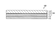
- FIG. 1 is a cross-sectional view schematically showing a polarizing plate obtained by the manufacturing method according to Embodiment 1 of the present invention.
- FIG. 2 is the figure which showed typically an example of the manufacturing process of laminated body [A].
- FIG. 3 is a cross-sectional view schematically showing a laminate [A] obtained through the manufacturing process shown in FIG.
- FIG. 4 is a view schematically showing an example of a production process of producing a polarizing plate from the laminate [A] in the production methods of the first to third embodiments.
- FIG. 5 is a cross-sectional view schematically showing a polarizing plate obtained by the manufacturing method according to Embodiment 2 of the present invention.
- FIG. 1 is a cross-sectional view schematically showing a polarizing plate obtained by the manufacturing method according to Embodiment 1 of the present invention.
- FIG. 2 is the figure which showed typically an example of the manufacturing process of laminated body [A].
- FIG. 3 is a cross-sectional view schematically
- FIG. 6 is a cross-sectional view schematically showing a polarizing plate obtained by the manufacturing method according to Embodiment 3 of the present invention.
- FIG. 7 is a cross-sectional view schematically showing a display device obtained by the manufacturing method according to Embodiment 4 of the present invention.
- FIG. 8 is a cross-sectional view schematically showing a display device obtained by the manufacturing method according to Embodiment 5 of the present invention.
- FIG. 9 is a cross-sectional view schematically showing a display device obtained by the manufacturing method according to Embodiment 6 of the present invention.
- FIG. 10 is a cross-sectional view schematically showing a display device obtained by the manufacturing method according to Embodiment 7 of the present invention.
- a "long film” refers to a film having a length of 5 times or more, preferably 10 times or more of the width of the film, and specifically, It has a length that can be rolled up and stored or transported.
- the upper limit of the ratio of the length to the width of the film is not particularly limited, and may be, for example, 100,000 times or less.
- the Nz coefficient of the film is a value represented by [(nx-nz) / (nx-ny)] and can also be represented as [(Rth / Re) +0.5].
- nx is the refractive index in the slow axis direction in the plane of the film (the maximum refractive index in the plane)
- ny is the refractive index in the direction perpendicular to the slow axis in the plane of the film
- nz is the refractive index in the thickness direction of the film
- d is the thickness (nm) of the film.
- the measurement wavelength is 590 nm, which is a typical wavelength in the visible light range.
- Embodiment 1 is a cross-sectional view schematically showing a polarizing plate 100 obtained by the manufacturing method of the present embodiment.
- the base film 112 is laminated on one surface (upper surface in the figure) of the polarizer material film 111.
- 113 is an adhesive layer.
- the adhesive layer 113 is contained in the polarizing plate 100 obtained by the manufacturing method of this embodiment, the polarizing plate obtained by the manufacturing method of this invention may be the structure which does not contain an adhesive layer.
- a raw material film containing a material of a polarizer is stretched in one or more directions at a draw ratio X to obtain a polarizer material film (a), on a polarizer material film
- a step (c) of stretching the laminate [A] in one or more directions at a draw ratio Z are included in this order.
- the manufacturing method of the polarizing plate of this embodiment includes the step (d) of dyeing the polarizer material film with a dichroic substance after the step (b).
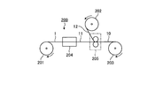
- FIG. 2 is schematic which shows typically an example of the manufacturing apparatus 200 which manufactures laminated body [A] obtained through a process (a) and a process (b).
- the manufacturing apparatus 200 includes feeding devices 201 and 202, a stretching device 204, a bonding device 205, and a winding device 203.
- the raw material film 1 fed out from the delivery device 201 is conveyed to the stretching device 204, and is stretched by the stretching device 204 to obtain the polarizer material film 11 (step (a)) ).
- the polarizer material film 11 thus obtained is conveyed to the bonding device 205, an adhesive is applied by the bonding device 205, and the substrate material film 12 fed out from the feeding device 202 is bonded.
- the laminate 10 is obtained (step (b)).
- the manufactured laminate 10 can be taken up by a take-up device 203, formed into a roll, and subjected to a further process.
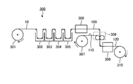
- FIG. 4 is the schematic which showed typically an example of the manufacturing apparatus 300 which manufactures the polarizing plate 100 of this embodiment through a process (c) and a process (d).
- the manufacturing apparatus 300 includes delivery devices 301 and 307, processing devices 302 to 305, drying devices 306 and 309, a bonding device 308, and a winding device 310.
- the laminate 10 delivered from the delivery device 301 is conveyed to the processing devices 302 to 305, and dyed with a dichroic substance (step (d)), and the laminate is stretched. Processing such as treatment (step (c)) is performed. When the laminate after these treatments is dried by the drying device 306, the polarizing plate 100 is obtained. Each step will be described in detail below.
- Step (a) is a step of drawing a raw material film containing a material of a polarizer in one or more directions at a draw ratio X to obtain a polarizer material film.
- a raw film is a film for obtaining a polarizer material film, and means a film not subjected to a stretching process (an unstretched film containing a material of a polarizer).
- the raw film is not necessarily limited as long as the object of the present invention can be achieved, but a film of polyvinyl alcohol resin is preferable in terms of cost performance.
- the polyvinyl alcohol resin (hereinafter sometimes abbreviated as PVA) is not necessarily limited, but it is produced by saponifying polyvinyl acetate obtained by polymerizing vinyl acetate from the viewpoint of availability etc. It is preferred to use
- the degree of polymerization of PVA is preferably in the range of 500 to 8000, and the degree of saponification is preferably 90% by mole or more, from the viewpoint of excellent stretchability and polarization performance of the obtained film.
- the degree of polymerization is an average degree of polymerization measured in accordance with the description of JIS K 6726-1994
- the degree of saponification is a value measured in accordance with the description of JIS K 6726-1994.
- a more preferable range of the polymerization degree is 1000 to 6000, and more preferably 1500 to 4000.
- a more preferable range of the degree of saponification is 95 mol% or more, more preferably 99 mol% or more.
- PVA may be a copolymer or graft polymer of vinyl acetate and other copolymerizable monomers, as long as the effect of the present invention is not adversely affected.
- the method of producing a raw film film of PVA is not particularly limited, and it can be produced by a known method.
- a cast film is produced using a PVA solution in which PVA is dissolved in a solvent Method, wet film forming method (ejection in poor solvent), dry / wet film forming method, gel film forming method (PVA aqueous solution is once cooled and gelled, then the solvent is extracted and removed to obtain a raw film of PVA And any combination thereof, and any method such as a melt extrusion film forming method in which a solution of PVA containing a solvent is melted is used as a film forming solution.
- the casting film forming method and the melt extrusion film forming method are preferable because a raw film of PVA having high transparency and little coloring is obtained, and the melt extrusion film forming method is more preferable.
- the raw material film of PVA has a plasticizer such as polyhydric alcohol such as glycerin, which is added to the PVA in an amount of 0.01 to 100%, in order to improve mechanical physical properties and process passability during secondary processing. It is preferable to contain 1% by mass, and in order to improve handleability, film appearance, etc., a surfactant such as an anionic surfactant or a nonionic surfactant is 0.01 to 30% by mass with respect to PVA. It is preferable to contain.
- the raw film of PVA is an antioxidant, an ultraviolet light absorber, a lubricant, a pH adjuster, inorganic fine particles, a coloring agent, an antiseptic agent, an anti-mildew agent, and the like, as needed, as long as the effects of the present invention are not impaired. It may further contain other components other than the components, such as polymer compounds and water.
- the raw film of PVA can contain one or more of these other components.
- the thickness of the raw film is preferably 50 ⁇ m or less, more preferably 40 ⁇ m or less, still more preferably 30 ⁇ m or less, preferably 5 ⁇ m or more, more preferably 10 ⁇ m or more, still more preferably 15 ⁇ m or more.
- the thickness of the raw film is at least the lower limit of the above range, it is possible to obtain a polarizing plate having a sufficiently high degree of polarization, and when it is below the upper limit of the above range, the bending resistance of the polarizing plate is effective. Can be enhanced.
- a polarizer material film is a film (film for polarizers) for manufacturing a polarizer.
- the polarizer material film is obtained by stretching the raw film in one or more directions at a stretching ratio X.
- a polarizer material film is a (stretched) film containing a polarizer material.
- dry stretching As a method of extending
- stretching methods such as tenter stretching, float stretching, and hot roll stretching can be used.
- the dry stretching refers to a method of stretching treatment in which a high temperature (for example, 100 ° C. or higher) gas atmosphere is used. Air can be mentioned as a gas used in dry stretching.
- the conditions for the stretching when the raw film is stretched into a polarizer material film may be appropriately selected so as to obtain a desired polarizer material film.
- the mode of stretching when the raw film is stretched to be a polarizer material film may be any mode such as uniaxial stretching or biaxial stretching.
- the stretching direction is the longitudinal direction (direction parallel to the longitudinal direction of the long film), and the transverse direction (parallel to the width direction of the long film).
- Direction and an oblique direction (direction that is neither vertical nor horizontal).
- the relationship between the stretching direction in step (a) and the stretching direction in step (c) will be described in the description of step (c).
- the draw ratio X is preferably 2.0 or more, more preferably 2.5 or more, and one side is preferably 4.5 or less, more preferably 3.5 or less. That is, the polarizer material film is preferably a film drawn at a draw ratio X of 2.0 to 4.5, and a film drawn at a draw ratio X of 2.5 to 3.5. Is more preferred.
- the draw ratio X When the draw ratio X is equal to or less than the upper limit value of the above range, occurrence of breakage can be prevented when the raw film is stretched to form a polarizer material film.
- the draw ratio X When the draw ratio X is at least the lower limit of the above range, the draw ratio when drawing the laminate to obtain a polarizing plate can be lowered.
- stretching of an original film is performed by extending
- the stretching temperature at the time of dry-stretching the raw film to obtain a polarizer material film is preferably 100 ° C. or more, more preferably 110 ° C. or more, and preferably 150 ° C. or less, more preferably 140 ° C. or less .
- a polarizer material film of uniform film thickness can be obtained.
- the thickness T1 of the polarizer material film is preferably 40 ⁇ m or less, more preferably 30 ⁇ m or less, still more preferably 20 ⁇ m or less, preferably 3 ⁇ m or more, more preferably 5 ⁇ m or more.
- the thickness T1 of the polarizer material film is at least the lower limit of the above range, a polarizing plate having a sufficiently high degree of polarization can be obtained, and when it is at the upper limit of the above range, resistance to bending of the polarizing plate Can be effectively enhanced.
- the retardation Re1 in the in-plane direction of the polarizer material film is preferably 10 nm or more, more preferably 50 nm or more, still more preferably 100 nm or more, preferably 500 nm or less, more preferably 400 nm or less.
- the retardation Re1 in the in-plane direction of the polarizer material film is equal to or more than the lower limit value of the above range, the draw ratio when drawing the laminate to form a polarizing plate is suppressed low, and the base material after the drawing treatment The phase difference of can be kept low.
- the draw ratio can be lowered when the raw film is stretched to make a polarizer material film, It is possible to avoid problems such as the occurrence of wrinkles when the film is stretched alone.
- the Nz coefficient of the polarizer material film is preferably 0.95 or more, more preferably 0.99 or more, preferably 1.5 or less, more preferably 1.4 or less. When the Nz coefficient is in the above range, a polarizer having a sufficient degree of polarization can be obtained.
- the shape and dimensions of the polarizer material film can be appropriately adjusted according to the desired application. From the viewpoint of production efficiency, the polarizer material film is preferably a long film.
- the step (b) is a step of providing a base film on the polarizer material film to obtain a laminate [A].
- a polarizer material film and a base film can be bonded together with an adhesive agent, and the layer of a base film can be provided on a polarizer material film.
- an adhesive is used in the step (b), but in the production method of the present invention, the adhesive is an optional component. Applying an adhesive between the polarizer material film and the base film is preferable in that problems such as peeling between the two films can be prevented, but it is preferable to use a polarizer material film without using an adhesive. An adhesive may not be used if sufficient adhesion with the substrate film can be obtained.
- the adhesive for bonding the polarizer material film and the base film there is no particular limitation on the adhesive for bonding the polarizer material film and the base film, and for example, an acrylic adhesive, a urethane adhesive, a polyester adhesive, a polyvinyl alcohol adhesive, a polyolefin adhesive , Modified polyolefin adhesive, polyvinyl alkyl ether adhesive, rubber adhesive, vinyl chloride-vinyl acetate adhesive, SEBS (styrene-ethylene-butylene-styrene copolymer) adhesive, ethylene-styrene copolymer It is possible to use an ethylene-based adhesive such as coalescing, an acrylic-ester-based adhesive such as ethylene- (meth) acrylate copolymer, and an ethylene- (meth) acrylate copolymer.
- an acrylic adhesive such as coalescing
- an acrylic-ester-based adhesive such as ethylene- (meth) acrylate copolymer
- the surface of the base film to be attached to the polarizer material film may be subjected to an easy adhesion treatment such as corona treatment, saponification treatment, primer treatment, anchor coating treatment and the like.
- the base film is formed of a resin.
- resin which forms a substrate film.
- the base film is preferably a film composed of at least one selected from cycloolefin resin, amorphous polyester resin, polyolefin resin, and acrylic resin, and more preferably a film composed of cycloolefin resin.
- the cycloolefin resin forming the base film includes a cycloolefin polymer, and the cycloolefin polymer is a hydride of a ring opening polymer of a norbornene monomer, an addition copolymer of a norbornene monomer and an ⁇ -olefin And its hydride is preferable.
- a cycloolefin polymer an addition copolymer of a norbornene monomer and an ⁇ -olefin, and a hydrogenated product thereof are preferable from the viewpoint that a retardation is hardly expressed even when stretched.
- a cycloolefin type polymer is included,
- the cycloolefin type polymer is a polymer block [A] which has repeating unit [I] derived from an aromatic vinyl compound as a main component
- hydrogen Preferred are those made of hydrogenated block copolymer and the like.
- the substrate film preferably contains a plasticizer and / or a softener (either one or both of the plasticizer and the softener).
- a plasticizer and / or a softener either one or both of the plasticizer and the softener.
- plasticizer and the softener those which can be uniformly dissolved or dispersed in the resin forming the base film can be used.
- specific examples of the plasticizer and the softener include an ester-based plasticizer composed of a polyhydric alcohol and a monovalent carboxylic acid (hereinafter referred to as "polyhydric alcohol ester-based plasticizer"), and a polyvalent carboxylic acid and a monovalent Ester-based plasticizers such as ester-based plasticizers (hereinafter referred to as "polyvalent carboxylic acid ester-based plasticizers") consisting of alcohols, and phosphoric acid ester-based plasticizers, carbohydrate ester-based plasticizers, and other polymer softeners Can be mentioned.
- Ethylene glycol glycerol, and trimethylol propane are preferable.
- polyhydric alcohol ester-based plasticizers examples include ethylene glycol ester-based plasticizers, glycerin ester-based plasticizers, and other polyhydric alcohol ester-based plasticizers.
- polyvalent carboxylic acid ester-based plasticizers examples include dicarboxylic acid ester-based plasticizers and other polyvalent carboxylic acid ester-based plasticizers.
- phosphoric acid ester plasticizers include phosphoric acid alkyl esters such as triacetyl phosphate and tributyl phosphate; phosphoric acid cycloalkyl esters such as tricyclophenyl phosphate and cyclohexyl phosphate; triphenyl phosphate and tricresyl phosphate And phosphoric acid aryl esters.
- carbohydrate ester plasticizers include glucose pentaacetate, glucose pentapropionate, glucose pentabutyrate, sucrose octaacetate, sucrose octabenzoate and the like, among which sucrose octaacetate is more preferred. preferable.
- polymer softener examples include aliphatic hydrocarbon polymers, alicyclic hydrocarbon polymers, polyethyl acrylate, polymethyl methacrylate, methyl methacrylate and 2-hydroxyethyl methacrylate.
- Acrylic polymers such as polymers, copolymers of methyl methacrylate, methyl acrylate and 2-hydroxyethyl methacrylate; vinyl polymers such as polyvinyl isobutyl ether, poly N-vinyl pyrrolidone, etc.
- polystyrene poly 4- Styrene-based polymers such as hydroxystyrene; polyesters such as polybutylene succinate, polyethylene terephthalate and polyethylene naphthalate; polyethers such as polyethylene oxide and polypropylene oxide; polyamides, polyurethanes, polyureas and the like.
- aliphatic hydrocarbon polymers include low molecular weight polymers such as polyisobutylene, polybutene, poly-4-methylpentene, poly-1-octene, ethylene / ⁇ -olefin copolymer, and their hydrides; polyisoprene And low molecular weight products such as polyisoprene-butadiene copolymer and the hydrides thereof.
- the aliphatic hydrocarbon-based polymer preferably has a number average molecular weight of 300 to 5,000, from the viewpoint of easy dissolution or dispersion in the cycloolefin resin uniformly.
- polymer softeners may be homopolymers consisting of one type of repeating unit or copolymers having a plurality of repeating structures. In addition, two or more of the above polymers may be used in combination.
- plasticizer and / or softener As the plasticizer and / or softener, ester plasticizers, aliphatic hydrocarbon polymers and mixtures thereof are preferable.
- the proportion of the plasticizer and / or the softener (hereinafter also referred to as “plasticizer etc.”) in the base film is preferably 0.2 parts by weight or more, more preferably 100 parts by weight of the resin forming the base film. Is 0.5 parts by weight or more, still more preferably 1.0 part by weight or more, and preferably 40 parts by weight or less, more preferably 30 parts by weight or less.
- the substrate film may contain optional components in addition to the resin and the plasticizer.
- optional components include stabilizers such as antioxidants, ultraviolet light absorbers, light stabilizers, etc .; resin modifiers such as lubricants; colorants such as dyes and pigments; and antistatic agents.
- stabilizers such as antioxidants, ultraviolet light absorbers, light stabilizers, etc .
- resin modifiers such as lubricants
- colorants such as dyes and pigments
- antistatic agents can be used singly or in combination of two or more kinds, and the compounding amount thereof is appropriately selected as long as the object of the present invention is not impaired.
- the base film forms a film (hereinafter, also referred to as a “resin composition”) containing a component (a resin and a component to be added as necessary) for forming the base film into a film by any forming method. It can be manufactured by molding.
- melt extrusion molding is mentioned.
- the melt extrusion process is a method of melting a resin composition by an extruder, extruding into a film form from a T die attached to the extruder, bringing the extruded film into close contact with one or more cooling rolls, shaping and taking it out It can be done by Molding conditions in melt extrusion molding can be appropriately set in accordance with conditions such as the composition and molecular weight of the resin composition to be used.
- the thickness of a base film 10 micrometers or more are more preferable, 50 micrometers or less are preferable, and 30 micrometers or less are more preferable.
- the thickness of the substrate film is at least the lower limit of the above range, a laminate with a good bonding surface shape can be obtained, and by being below the upper limit of the above range, the laminate is stretched and polarized When a plate is obtained, the phase difference generated in the base film can be reduced.
- FIG. 3 is a cross-sectional view schematically showing a laminate [A] obtained through the step (b).
- the laminate 10 includes a stretched polarizer material film 11, an adhesive layer 13, and a base film 12.
- the laminate obtained through the step (b) may have a configuration not including the adhesive layer.
- it in order to distinguish the laminate [A] before the stretching treatment in the step of producing the polarizing plate and the laminate after the stretching treatment in the step of producing the polarizing plate, It may be called "stretched laminate".
- Step (c) is a step of drawing the laminate [A] obtained through the step (b) in one or more directions at a draw ratio Z.
- the method of stretching the laminate [A] is not particularly limited, but wet stretching is preferred.
- the draw ratio Z of the laminate [A] in the step (c) is 1.2 or more and 5.0 or less, and the above-mentioned formula (2) (1.2 ⁇ Z ⁇ 5.0) is satisfied.
- the draw ratio Z is preferably 1.5 or more, more preferably 2.0 or more, and preferably 4.5 or less, more preferably 4.0 or less.
- the product of the draw ratio X in step (a) and the draw ratio Z of the laminate in step (c) (hereinafter also referred to as "product of draw ratio") is 5.1 or more and 9.0 or less And satisfy the above-mentioned equation (3) (5.1 ⁇ X * Z ⁇ 9.0).
- the product (X * Z) of the draw ratio is preferably 5.5 or more, more preferably 6.0 or more, preferably 8.0 or less, more preferably 7.0 or less.
- the stretching temperature of the laminate [A] in the step (c) is not particularly limited.
- the specific stretching temperature is preferably 50 ° C. or more, more preferably 55 ° C. or more, particularly preferably 60 ° C. or more, preferably 160 ° C. or less.
- the temperature is more preferably 120 ° C. or less, particularly preferably 110 ° C. or less.
- the range of the stretching temperature is preferably either dry stretching or wet stretching, but is particularly preferred in the case of wet stretching.
- the stretching treatment of the laminate [A] in the step (c) is a treatment including stretching in at least one direction, may include only stretching in one direction, and includes stretching in two or more directions. It is also good.
- uniaxial stretching is preferable, free end uniaxial stretching is more preferable, and free end uniaxial stretching in the longitudinal direction is particularly preferable.
- the stretching is performed such that the stretching magnification of the stretching falls within the predetermined stretching magnification range.
- the stretching is performed such that the product of the stretching ratio of each stretching falls within the range of the predetermined stretching ratio.
- the stretching may be performed simultaneously or sequentially.
- the stretching direction in step (a) and the stretching direction in step (c) will be described.
- the stretching direction of the original film in the step (a) and the stretching direction of the laminate [A] in the step (c) are not particularly limited, but may be in the embodiments shown in the following (1) to (6) it can.
- the stretching direction in which the stretching ratio is larger is taken as the stretching direction in that step.
- ⁇ 1 and ⁇ 2 can include tolerances within the range that does not impair the effects of the present invention. For example, if .theta.1 and .theta.2 are 0.degree.
- the angle ⁇ 1 between the stretching direction in the step (a) and the width direction of the polarizer material film and the angle ⁇ 2 between the stretching direction in the step (c) and the width direction of the laminate [A] are as follows. be able to. (1) ⁇ 1 is 90 ° and ⁇ 2 is 90 °. (2) ⁇ 1 is 0 ° and ⁇ 2 is 0 °. (3) One of ⁇ 1 and ⁇ 2 is 90 °, and the other is 0 °. (4) ⁇ 1 is 90 °, ⁇ 2 (°) satisfies the following formula (4). ⁇ 2 ⁇ 90 (4) (5) ⁇ 1 (°) satisfies the following formula (5), and ⁇ 2 is 90 °. ⁇ 1 ⁇ 90 (5) (6) ⁇ 1 (°) and ⁇ 2 (°) satisfy the following formula (6) and the following formula (7). ⁇ 1 ⁇ 90 (6) ⁇ 2 ⁇ 90 (7)
- the above aspect (1) is preferable when the application of the polarizing plate is a polarizing plate for a liquid crystal display device, and (4) to (6) is preferable when the polarizing plate for an EL display device.
- the absolute value of the difference between ⁇ 1 and ⁇ 2 is preferably 50 or less, more preferably 30 or less, and still more preferably 10 or less.
- Step (d) is a step of dyeing the polarizer material film with a dichroic substance.
- the manufacturing method of this embodiment includes a step (d), it is an optional step in the manufacturing method of the present invention.
- the step (d) may be performed after the step (b) before the step (c).
- the dyeing of the polarizer material film may be performed on the polarizer material film before forming the laminate [A].
- the polarizer material film is stretched and optionally dyed, resulting in a film that can function as a polarizer.
- the dyeing may be performed by immersing the layer of the polarizer material film in a dyeing solution containing a dichroic substance.
- the staining solution may contain an iodide such as potassium iodide from the viewpoint of enhancing the staining efficiency.
- the dichroic substance is not particularly limited, but when the polarizing plate is used in a vehicle-mounted display, an organic dye is preferable as the dichroic substance.
- the polarizing plate of the present embodiment is obtained.
- the thickness T of the polarizer material film after passing through the step (c) (after stretching the laminate) is 20 ⁇ m or less.
- the thickness T of the polarizer material film is preferably 15 ⁇ m or less, more preferably 10 ⁇ m or less, preferably 1 ⁇ m or more, and more preferably 3 ⁇ m or more.
- the thickness T is not more than the upper limit value, the thickness of the polarizing plate can be reduced, and when the thickness T is not less than the lower limit value, a polarizing plate having a sufficiently high degree of polarization can be obtained.
- the phase difference Re in the in-plane direction of the base film after passing through the step (c) is preferably 20 nm or less.
- the retardation Re in the in-plane direction of the base film is more preferably 15 nm or less, still more preferably 10 nm or less, and preferably 0 nm or more.
- the retardation Re in the in-plane direction of the substrate film is in the above range, the substrate film is sufficiently low in the expression of retardation even after passing through the manufacturing process of the polarizing plate including the stretching treatment. can do.
- the polarizing plate is manufactured by stretching the laminate [A] including the polarizer material film stretched in advance, which is obtained in the step (a), the laminate [A] is stretched. It is possible to lower the draw ratio when manufacturing a polarizing plate. Thereby, since expression of a phase difference in the substrate film after stretching treatment of the laminate [A] can be suppressed, as the protective film of one surface of the polarizer material film as it is without peeling the substrate film. It can be used and waste material can be reduced.
- a base film can be used also as a protective film, and even if thickness is thin, the manufacturing method of the polarizing plate which can be manufactured efficiently can be provided.
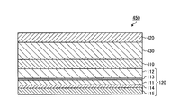
- FIG. 5 is a cross-sectional view schematically showing a polarizing plate 120 obtained by the method of manufacturing a polarizing plate according to Embodiment 2 of the present invention.
- the base film 112 is laminated on one side (upper side in the figure) of the polarizer material film 111, and the other side of the polarizer material film 111 A protective film 115 is laminated on the lower side of the drawing.
- 113 and 114 are adhesive layers.
- the adhesive for bonding the protective film to the polarizer material film may be the same as the adhesive for bonding the base film to the polarizer material film.
- the manufacturing method of the polarizing plate 120 which concerns on this embodiment is a polarizer material of the extending
- the polarizing plate 100 of Embodiment 1 is conveyed to the laminating apparatus 308, and an adhesive is applied to the surface of the polarizer material film 111 on the side where the base film 112 is not laminated.
- the polarizing plate 120 provided with the protective film 115 is obtained by applying and bonding the protective film 115 delivered from the delivery device 307 (step (e1)).
- the manufactured polarizing plate 120 can be taken up by a take-up device 310, formed into a roll, and subjected to a further process.
- the polarizing plate obtained by the manufacturing method of the present embodiment is also obtained by stretching the laminate including the polarizer material film drawn in advance and obtained in the step (a). Have the same effects as in the first embodiment.
- Embodiment 3 Method of Manufacturing Polarizing Plate
- FIG. 6 is a cross-sectional view schematically showing a polarizing plate 130 obtained by the method of manufacturing a polarizing plate according to Embodiment 3 of the present invention.
- the base film 112 is laminated on one side (upper side in the figure) of the polarizer material film 111, and the other side of the polarizer material film 111
- the adhesive layer 116 is laminated on the lower side of the drawing.
- the manufacturing method of the polarizing plate of this embodiment is the polarizer material film of the stretched laminated body after the above-mentioned process (a), process (b), process (d) and process (c) and process (c)
- the process (e2) of providing an adhesive layer is included.
- the polarizing plate 130 according to the third embodiment is, for example, a film having a commercially available pressure-sensitive adhesive layer on the surface of the polarizing plate 100 of the first embodiment on which the base material film 112 of the polarizer material film 111 is not laminated.
- it can be obtained by transferring the pressure-sensitive adhesive layer from “Mustrak series” manufactured by Fujimori Kogyo, and forming the pressure-sensitive adhesive layer.
- the polarizing plate obtained by the manufacturing method of the present embodiment is also obtained by stretching the laminate including the polarizer material film drawn in advance and obtained in the step (a). Have the same effects as in the first embodiment.
- the polarizing plate obtained by the method for producing a polarizing plate of the present invention can be a material of a liquid crystal display.
- the liquid crystal display device comprises a light source, a light source side polarizing plate, a liquid crystal cell and a viewing side polarizing plate in this order, but the polarizing plate obtained by the present invention is either the light source side polarizing plate or the viewing side polarizing plate You may use.
- IPS in-plane switching
- VA vertical alignment
- MVA multidomain vertical alignment
- CPA continuous spin wheel alignment
- HAN hybrid alignment nematic
- TN twisted nematic
- STN super twisted nematic
- OBC optically compensated bend
- FIG. 1 a display device is manufactured by laminating the polarizing plate of the present invention as a light source side polarizing plate and a viewing side polarizing plate on a liquid crystal panel.
- FIG. 7 is a cross-sectional view schematically showing a liquid crystal display device 400 obtained by the manufacturing method according to the fourth embodiment.
- the liquid crystal display device 400 includes two substrates 410 and 420, a liquid crystal layer 430 positioned therebetween, and polarizing plates 100 and 100 disposed outside the two substrates 410 and 420, respectively.
- the two polarizing plates 100 are the polarizing plates of the first embodiment.
- the two polarizing plates 100 are laminated such that the base film 112 is disposed between the polarizer material film 111 and the liquid crystal layer 430, as shown in FIG. ing.
- the present embodiment it is possible to provide a method for producing a display device provided with the polarizing plate of the present invention, which can be used as a protective film and can be efficiently produced even if the thickness is thin. Can.
- FIG. 8 is a cross-sectional view schematically showing a liquid crystal display device 450 obtained by the manufacturing method according to Embodiment 5 of the present invention. As shown in FIG.
- the liquid crystal display device 450 includes two substrates 410 and 420, a liquid crystal layer 430 positioned therebetween, and a polarizing plate 120 disposed on the outer side (lower side in the figure) of the lower substrate 410.
- the polarizing plate 120 is the polarizing plate of the second embodiment. As shown in FIG. 8, the polarizing plate 120 is laminated such that the base film 112 is disposed between the polarizer material film 111 and the liquid crystal layer 430.
- the present embodiment it is possible to provide a method for producing a display device provided with the polarizing plate of the present invention, which can be used as a protective film and can be efficiently produced even if the thickness is thin. Can.
- the polarizing plate obtained by the method for producing a polarizing plate of the present invention can be a material of an EL display device.
- the organic EL display device comprises, in order from the light emitting side, a substrate, a transparent electrode, a light emitting layer and a metal electrode layer, but the polarizing plate obtained by the manufacturing method of the present invention is disposed on the light emitting side of the substrate. Ru.
- the EL display device has two substrates, a light emitting layer positioned between them, and a polarizing plate disposed outside one of the two substrates.
- the display device can be manufactured by laminating the polarizing plate of the present invention on an organic EL panel or an inorganic EL panel.
- FIG. 9 is a cross-sectional view schematically showing an organic EL display device 500 obtained by the manufacturing method according to Embodiment 6 of the present invention.
- the organic EL display device 500 includes two substrates 510 and 520, a light emitting layer 530 positioned between them, and a polarizing plate 100 disposed on the outer side (lower side in the drawing) of the lower substrate 510.
- the polarizing plate 100 is the polarizing plate of the first embodiment. As shown in FIG. 9, the polarizing plate 100 is laminated such that the base film 112 is disposed between the polarizer material film 111 and the light emitting layer 530.
- the present embodiment it is possible to provide a display device provided with the polarizing plate of the present invention, which can be used as a protective film and can be efficiently manufactured even if the thickness is thin.
- FIG. 10 is a cross-sectional view schematically showing an organic EL display device 550 obtained by the manufacturing method according to Embodiment 7 of the present invention.
- the organic EL display device 550 has two substrates 510 and 520, a light emitting layer 530 positioned therebetween, and a polarizing plate 120 disposed on the outer side (lower side in the drawing) of the lower substrate 510.
- the polarizing plate 120 is the polarizing plate of the second embodiment. As shown in FIG. 10, the polarizing plate 120 is laminated such that the base film 112 is disposed between the polarizer material film 111 and the light emitting layer 530.
- the present embodiment it is possible to provide a display device provided with the polarizing plate of the present invention, which can be used as a protective film and can be efficiently manufactured even if the thickness is thin.
- the polarizing plate of the first embodiment is used as each of the light source side polarizing plate and the viewing side polarizing plate.
- any one of the polarizing plates is the polarizing plate of the second or third embodiment.
- two polarizing plates of Embodiment 2 or 3 may be used.
- the polarizing plate of the second embodiment is used as one of the light source side polarizing plate and the viewing side polarizing plate, but the polarizing plate of the first or third embodiment may be used.
- the polarizing plate of Embodiment 3 may be used for the inorganic EL display device.
- the hydrogenation rate of the block copolymer hydride was calculated by 1 H-NMR spectrum or GPC analysis.
- the region having a hydrogenation rate of 99% or less was calculated by measuring 1 H-NMR spectrum, and the region exceeding 99% was calculated by GPC analysis from the ratio of peak areas by a UV detector and an RI detector.
- Re and Rth were measured using a retardation measurement apparatus (product name “Axoscan” manufactured by Axometric Corporation) at a wavelength of 590 nm, and the Nz coefficient was determined based on them.
- the thickness before and after stretching of the raw film, the thickness of the base film, and the thickness of each layer contained in the polarizing plate were measured by the following methods. After cutting the polarizing plate using a microtome, its cross section was observed using a TEM. The size in the thickness direction was measured at five locations, and the average of the measured values was adopted as the thickness.
- Ts The single transmittance (Ts), the parallel transmittance (Tp) and the orthogonal transmittance (Tc) of the polarizing plate were measured using an ultraviolet-visible spectrophotometer (product name "V7100" manufactured by JASCO Corporation), and the degree of polarization (P) was determined by the following equation.
- Ts, Tp, and Tc are Y values which were measured by the visual field (C light source) of JIS Z 8701 and subjected to the visual sensitivity correction.
- Degree of polarization (P) (%) ⁇ (Tp-Tc) / (Tp + Tc) ⁇ 1/2 ⁇ 100 The measurement was performed so that the polarizer material film side of the polarizing plate was on the light incident side.
- Example 1 (1-1) Production of Substrate Film (1-1-1) Production of Polymer X
- 25 parts of styrene monomer is polymerized in the first step
- 30 parts of styrene monomer and 25 parts of isoprene monomer are polymerized in the second step
- 20 parts of styrene monomer is polymerized in the third step to obtain a block copolymer [D1], and then the block copolymer is obtained.
- the coalesced was hydrogenated to synthesize block copolymer hydride [E1].
- Mw of the block copolymer hydride [E1] was 84,500, Mw / Mn was 1.20, and the hydrogenation rate of the main chain and the aromatic ring was almost 100%.
- 100 parts of block copolymer hydride [E1], pentaerythrityl tetrakis [3- (3,5-di-t-butyl-4-hydroxyphenyl) propionate] (manufactured by Matsubara Sangyo Co., Ltd.) as an antioxidant
- 0.1 parts of the name "Songnox 1010” was melt-kneaded and blended, it was pelletized to obtain a polymer X for molding.
- the polymer X produced in (1-1-1) was supplied to a hot melt extruded film molding machine equipped with a T-die.
- the polymer X was formed into a film by extruding the polymer X from the T die and winding it on a roll at a take-up speed of 4 m / min. Thereby, the elongate base film A (20 micrometers in thickness) which consists of the polymer X was obtained.
- Step (a) As a raw film, an unstretched polyvinyl alcohol film (average polymerization degree about 2400, saponification degree 99.9 mol%, thickness 20 ⁇ m, hereinafter referred to as “PVA 20”) was used. The raw film was dry stretched at a stretching temperature of 130 ° C. in the longitudinal direction at a stretching ratio of 3.0 using a longitudinal uniaxial stretching machine to obtain a polarizer material film.
- the thickness T1 of the polarizer material film was 12 ⁇ m, the in-plane retardation Re1 was 345 nm, and the Nz coefficient was 1.0.
- Step (b) 100 parts by weight of water, 3 parts by weight of a polyvinyl alcohol-based adhesive ("Z-200" manufactured by Nippon Synthetic Chemical Co., Ltd.), and 0.3 parts by weight of a crosslinking agent ("SPM-01” manufactured by Japan Synthetic Chemical Co., Ltd.)
- the adhesive composition was obtained.
- One surface of the substrate film A obtained in (1-1-2) was subjected to corona treatment, the adhesive composition was coated thereon, and it was bonded to one surface of the polarizer material film. In this state, the adhesive composition was dried by heating at 70 ° C. for 5 minutes.
- a laminate [A] having a layer structure of “polarizer material film” / “adhesive layer” / “base film A” was obtained.
- the thickness of the adhesive layer was 1 ⁇ m.
- the base film A in the said laminated body [A] is an unstretched film.
- the bonding surface state of the obtained laminate [A] was evaluated. The results are shown in Table 1.
- step (1-4) Production of polarizing plate (wet process) (step (d), step (c))
- the following operation was performed while continuously conveying the laminate [A] obtained in (1-3) in the longitudinal direction via a guide roll.
- stretches the laminated body after a dyeing process were performed.
- the laminate after the first stretching was subjected to a second stretching in a 65 ° C. acid bath containing boric acid and potassium iodide.
- the total draw ratio represented by the product of the draw ratio in the first drawing process and the draw ratio in the second drawing process was set to be 2.0.
- the stretched laminate after the second stretching treatment was dried at 70 ° C. for 5 minutes in a drier to obtain a polarizing plate. Thickness of polarizing plate (total thickness), thickness of substrate film (substrate thickness) and retardation Re (substrate Re) of polarizing plate, thickness T of polarizer material film, and polarization at single transmittance 42.8%
- the degree (%) was measured, and is shown in Table 1 together with the evaluation result of the stretchability.
- Example 2 A polarizing plate was manufactured in the same manner as in Example 1 except that the polarizer material film obtained in (2-2) below was used instead of the polarizer material film obtained in (1-2). The evaluation was carried out in the same manner as in Example 1, and the results are shown in Table 1.
- An unstretched polyvinyl alcohol film (average polymerization degree about 2400, saponification degree 99.9 mol%, thickness 30 ⁇ m, hereinafter also referred to as “PVA 30”) is used as a raw film. It was.
- the raw film (PVA 30) was stretched at a stretching temperature of 130 ° C. in the longitudinal direction at a stretching ratio of 3.0 using a longitudinal uniaxial stretching machine to obtain a polarizer material film.
- the thickness T1 of the polarizer material film was 17 ⁇ m, and Re1 was 520 nm.
- Example 3 Instead of the polarizer material film obtained in (1-2), a laminate [A] was produced using the polarizer material film obtained in (3-2) below, and (1-4 The polarizing plate was manufactured in the same manner as in Example 1 except that the drawing ratio was changed to thereby change the total drawing ratio to 3.0, and the evaluation was carried out in the same manner as in Example 1. Shown in 1.
- Example 4 Using the polarizer material film obtained in the following (4-2) instead of the polarizer material film obtained in (1-2), the following method (4-3) and (4-4) A polarizing plate was produced by the method of 1. and evaluated in the same manner as in Example 1. The results are shown in Table 1.
- Example 5 Using the polarizer material film obtained in the following (5-2) instead of the polarizer material film obtained in (1-2), the following method (5-3) and (5-4) A polarizing plate was produced by the method of 1. and evaluated in the same manner as in Example 1. The results are shown in Table 1.
- Example 6 Using the polarizer material film obtained in the following (6-2) instead of the polarizer material film obtained in (1-2), the following method (6-3) and (6-4) A polarizing plate was produced by the method of 1. and evaluated in the same manner as in Example 1. The results are shown in Table 1.
- Example 7 Using the laminate [A] obtained in (1-3), a polarizing plate was produced by the method of (7-4) below, evaluated in the same manner as in Example 1 and the results are shown in Table 2 .
- Example 8 A polarizing plate is manufactured in the same manner as Example 1, except that the polarizer material film obtained in (8-2) below is used instead of the polarizer material film obtained in (1-2) The evaluation was performed in the same manner as in Example 1. The results are shown in Table 2.
- the thickness T1 of the polarizer material film was 7 ⁇ m, and Re1 was 310 nm.
- Example 9 Using the polarizer material film obtained in the following (9-2) instead of the polarizer material film obtained in (1-2), the following method (9-3) and (9-4) A polarizing plate was produced by the method of 1. and evaluated in the same manner as in Example 1. The results are shown in Table 2.
- Example 10 (10-1) Production of Substrate Film B The same as (1-1) except that the conditions for extruding the polymer X in (1-1-2) were changed to obtain a thickness of 25 ⁇ m. Thus, a long base film B (thickness 25 ⁇ m) made of the polymer X was obtained.
- Laminate [A] The substrate film obtained in (10-1) in place of the substrate film A using the polarizer material film obtained in (11-2) instead of the polarizer material film obtained in (1-2) A laminate [A] having a layer structure of “polarizer material film” / “adhesive layer” / “base film B” was obtained in the same manner as (1-3) except that B was used.
- Example 12 (12-2) Production of Polarizer Material Film A polarizer material film was obtained in the same manner as (1-2) except that the raw film (PVA 20) was drawn at a draw ratio of 3.5.
- the thickness T1 of the polarizer material film was 11 ⁇ m, and Re1 was 340 nm.
- Laminate [A] A substrate film B obtained in (10-1) in place of the substrate film A using the polarizer material film obtained in (12-2) instead of the polarizer material film obtained in (1-2)
- a laminate [A] having a layer structure of “polarizer material film” / “adhesive layer” / “base film B” was obtained in the same manner as (1-3) except using.
- Laminate [A] A substrate film B obtained in (10-1) in place of the substrate film A using the polarizer material film obtained in (13-2) instead of the polarizer material film obtained in (1-2) A laminate [A] having a layer structure of “polarizer material film” / “adhesive layer” / “base film B” was obtained in the same manner as (1-3) except using.
- Example 14 A polarizing plate was manufactured in the same manner as in Example 1, except that the base film D obtained in (14-1) below was used instead of the base film A obtained in (1-1). The evaluation was carried out in the same manner as in Example 1, and the results are shown in Table 3.
- Example 15 A polarizing plate is manufactured by the method of the following (15-4) using the laminate [A] obtained in the following (15-3), evaluated in the same manner as in Example 1, and the results are shown in Table 3. Indicated.
- Example 16 A polarizing plate was manufactured by the following method (16-4) using the laminate [A] obtained in (16-3), and evaluated in the same manner as in Example 1. The results are shown in Table 3 .
- the laminate [A] obtained in (16-3) is dyed by immersing it in a dyeing solution containing CI Direct Red 81, sodium tripolyphosphate, and anhydrous sodium sulfate. Done and dried in the dryer at 70 ° C. for 5 minutes.
- the processed product of the obtained laminate [A] was stretched at a stretching temperature of 110 ° C. in the longitudinal direction at a stretching ratio of 2.0 using a longitudinal uniaxial stretching machine. Subsequently, the resultant was dipped in an acid bath containing boric acid and crosslinked, and dried at 70 ° C. for 5 minutes to obtain a polarizing plate.
- the thickness of the base film was 18 ⁇ m, and the retardation was 1 nm.
- the thickness of the polarizer material film of the stretched laminate was 8 ⁇ m.
- Example 17 A polarizing plate was manufactured by the following method, evaluated in the same manner as in Example 1, and the results are shown in Table 3.
- Example 18 A polarizing plate was manufactured by the following method (18-4) using the laminate [A] obtained in (18-3), and evaluated in the same manner as in Example 1. The results are shown in Table 3 .
- Comparative Example 2 (C2-2) Production of Polarizer Material Film A polarizer material film was obtained in the same manner as (1-2) except that the stretching ratio was changed to 5.7.
- the thickness T1 of the polarizer material film was 8 ⁇ m, and Re1 was 320 nm.
- a polyvinyl alcohol (PVA) layer was formed on the surface of a base film C4 according to the following procedure to produce a laminate [A].
- a base film C4 a base film (200 ⁇ m thick) of a continuous web of amorphous polyethylene terephthalate (amorphous PET, glass transition temperature: 75 ° C.) obtained by copolymerizing 6 mol% of isophthalic acid was used.
- the PVA aqueous solution is applied to one surface of the base film C4 and dried at a temperature of 50 to 60 ° C. to form a PVA layer on the surface of the base film C4 to form a layer structure of PVA layer / base film C4.
- a laminate [A] having the In this comparative example, the PVA layer is formed by applying and drying a PVA aqueous solution, but the thickness and the phase difference in the in-plane direction of the layer can be determined by comparing “thickness T1 after stretching” and “position after stretching”. Each is described in the column of "Retardation Re1".
- (C4-4) Production of Polarizing Plate The laminate [A] obtained in (C4-3) was subjected to a stretching apparatus installed in an oven set to a stretching temperature environment of 130 ° C., and the stretching ratio was 1.8 times. The free end uniaxial stretching was performed so as to be (1st stretching processing).
- the laminate [A] after the first stretching treatment was subjected to a dyeing treatment in which the laminate [A] was immersed in a dyeing solution containing iodine and potassium iodide.
- the laminate [A] after the dyeing process is subjected to a stretching apparatus installed in a processing apparatus set to a boric acid aqueous solution containing boric acid and potassium iodide at 65 ° C., and the draw ratio becomes 3.3 times
- the stretching process was performed on the free end uniaxially (second stretching process).
- the stretching direction was the longitudinal direction in both the first stretching process and the second stretching process.
- the laminate [A] after the second stretching treatment is taken out from the aqueous boric acid solution, and the boric acid attached to the surface of the 3 ⁇ m-thick PVA layer formed on the amorphous PET substrate is washed with an aqueous potassium iodide solution
- the sheet was dried by a drying process with warm air at 60 ° C. to obtain a polarizing plate.
- the thickness of the base film and the retardation Re (base Re) of the polarizing plate, the thickness T of the PVA layer, the overall thickness, and the degree of polarization were measured, and are shown in Table 4 together with the evaluation results of stretchability.
Priority Applications (3)
| Application Number | Priority Date | Filing Date | Title |
|---|---|---|---|
| CN201880048316.4A CN110998379B (zh) | 2017-07-25 | 2018-07-23 | 偏振片的制造方法和显示装置的制造方法 |
| JP2019532607A JP7107316B2 (ja) | 2017-07-25 | 2018-07-23 | 偏光板の製造方法及び表示装置の製造方法 |
| KR1020207001905A KR102530378B1 (ko) | 2017-07-25 | 2018-07-23 | 편광판의 제조 방법 및 표시 장치의 제조 방법 |
Applications Claiming Priority (2)
| Application Number | Priority Date | Filing Date | Title |
|---|---|---|---|
| JP2017143265 | 2017-07-25 | ||
| JP2017-143265 | 2017-07-25 |
Publications (1)
| Publication Number | Publication Date |
|---|---|
| WO2019022024A1 true WO2019022024A1 (ja) | 2019-01-31 |
Family
ID=65039722
Family Applications (1)
| Application Number | Title | Priority Date | Filing Date |
|---|---|---|---|
| PCT/JP2018/027549 WO2019022024A1 (ja) | 2017-07-25 | 2018-07-23 | 偏光板の製造方法及び表示装置の製造方法 |
Country Status (5)
| Country | Link |
|---|---|
| JP (1) | JP7107316B2 (ko) |
| KR (1) | KR102530378B1 (ko) |
| CN (1) | CN110998379B (ko) |
| TW (1) | TWI767034B (ko) |
| WO (1) | WO2019022024A1 (ko) |
Cited By (1)
| Publication number | Priority date | Publication date | Assignee | Title |
|---|---|---|---|---|
| WO2020153233A1 (ja) * | 2019-01-23 | 2020-07-30 | 日本ゼオン株式会社 | 積層体、偏光板、積層体の製造方法、偏光板の製造方法及び表示装置の製造方法 |
Citations (5)
| Publication number | Priority date | Publication date | Assignee | Title |
|---|---|---|---|---|
| JP2015055705A (ja) * | 2013-09-11 | 2015-03-23 | 日東電工株式会社 | 光学フィルム積層体の製造方法 |
| JP2015191224A (ja) * | 2014-03-31 | 2015-11-02 | 日東電工株式会社 | 延伸積層体の製造方法および延伸積層体、ならびに偏光膜の製造方法および偏光膜 |
| JP2015203828A (ja) * | 2014-04-16 | 2015-11-16 | 日東電工株式会社 | 延伸積層体およびその製造方法 |
| JP2017097048A (ja) * | 2015-11-19 | 2017-06-01 | 日本合成化学工業株式会社 | 偏光板用積層体および偏光板 |
| JP2017102439A (ja) * | 2015-11-19 | 2017-06-08 | 日本合成化学工業株式会社 | 偏光膜製造用ポリビニルアルコール系フィルム、およびそれを用いた偏光膜、偏光板、ならびに偏光膜製造用ポリビニルアルコール系フィルムの製造方法 |
Family Cites Families (9)
| Publication number | Priority date | Publication date | Assignee | Title |
|---|---|---|---|---|
| JP4691205B1 (ja) | 2010-09-03 | 2011-06-01 | 日東電工株式会社 | 薄型高機能偏光膜を含む光学フィルム積層体の製造方法 |
| KR101740763B1 (ko) * | 2010-11-10 | 2017-05-26 | 스미또모 가가꾸 가부시키가이샤 | 편광성 적층 필름 및 편광판의 제조 방법 |
| JP5969180B2 (ja) * | 2011-08-02 | 2016-08-17 | 日東電工株式会社 | 処理フィルムの製造方法及びその製造装置 |
| JP5607673B2 (ja) * | 2012-03-09 | 2014-10-15 | 日東電工株式会社 | 光学的表示装置 |
| KR101578610B1 (ko) | 2013-06-18 | 2015-12-17 | 주식회사 엘지화학 | 연신 적층체, 박형 편광자의 제조 방법, 이를 이용하여 제조되는 박형 편광자 및 이를 포함하는 편광판 |
| CN105359011A (zh) * | 2013-07-01 | 2016-02-24 | 日本瑞翁株式会社 | 光学用膜及其制造方法 |
| JP6363344B2 (ja) * | 2014-01-07 | 2018-07-25 | 日東電工株式会社 | 粘着剤層付き片保護偏光フィルムの製造方法 |
| JPWO2015159679A1 (ja) * | 2014-04-16 | 2017-04-13 | コニカミノルタ株式会社 | 偏光板、偏光板の製造方法、液晶表示装置及び有機エレクトロルミネッセンス表示装置 |
| JP2016200709A (ja) * | 2015-04-10 | 2016-12-01 | コニカミノルタ株式会社 | 偏光板保護フィルム、それが具備された偏光板及び偏光板保護フィルムの製造方法 |
-
2018
- 2018-07-23 WO PCT/JP2018/027549 patent/WO2019022024A1/ja active Application Filing
- 2018-07-23 JP JP2019532607A patent/JP7107316B2/ja active Active
- 2018-07-23 CN CN201880048316.4A patent/CN110998379B/zh active Active
- 2018-07-23 KR KR1020207001905A patent/KR102530378B1/ko active IP Right Grant
- 2018-07-24 TW TW107125487A patent/TWI767034B/zh active
Patent Citations (5)
| Publication number | Priority date | Publication date | Assignee | Title |
|---|---|---|---|---|
| JP2015055705A (ja) * | 2013-09-11 | 2015-03-23 | 日東電工株式会社 | 光学フィルム積層体の製造方法 |
| JP2015191224A (ja) * | 2014-03-31 | 2015-11-02 | 日東電工株式会社 | 延伸積層体の製造方法および延伸積層体、ならびに偏光膜の製造方法および偏光膜 |
| JP2015203828A (ja) * | 2014-04-16 | 2015-11-16 | 日東電工株式会社 | 延伸積層体およびその製造方法 |
| JP2017097048A (ja) * | 2015-11-19 | 2017-06-01 | 日本合成化学工業株式会社 | 偏光板用積層体および偏光板 |
| JP2017102439A (ja) * | 2015-11-19 | 2017-06-08 | 日本合成化学工業株式会社 | 偏光膜製造用ポリビニルアルコール系フィルム、およびそれを用いた偏光膜、偏光板、ならびに偏光膜製造用ポリビニルアルコール系フィルムの製造方法 |
Cited By (1)
| Publication number | Priority date | Publication date | Assignee | Title |
|---|---|---|---|---|
| WO2020153233A1 (ja) * | 2019-01-23 | 2020-07-30 | 日本ゼオン株式会社 | 積層体、偏光板、積層体の製造方法、偏光板の製造方法及び表示装置の製造方法 |
Also Published As
| Publication number | Publication date |
|---|---|
| CN110998379B (zh) | 2021-12-31 |
| JPWO2019022024A1 (ja) | 2020-05-28 |
| JP7107316B2 (ja) | 2022-07-27 |
| KR102530378B1 (ko) | 2023-05-09 |
| TWI767034B (zh) | 2022-06-11 |
| CN110998379A (zh) | 2020-04-10 |
| KR20200035260A (ko) | 2020-04-02 |
| TW201908785A (zh) | 2019-03-01 |
Similar Documents
| Publication | Publication Date | Title |
|---|---|---|
| US11573359B2 (en) | Method for producing a polarizing plate | |
| JP7192797B2 (ja) | 偏光板用積層体、偏光板、積層体フィルムロール、偏光板用積層体の製造方法及び偏光板の製造方法 | |
| JP7140121B2 (ja) | 積層体及び偏光板の製造方法 | |
| JP7107316B2 (ja) | 偏光板の製造方法及び表示装置の製造方法 | |
| JP7124829B2 (ja) | 積層体及び偏光板の製造方法 | |
| JP7140122B2 (ja) | 積層体及び偏光板の製造方法 | |
| JP7294142B2 (ja) | 偏光板用積層体、偏光板、表示装置、及び偏光板の製造方法 | |
| WO2019131666A1 (ja) | 偏光板用積層体、偏光板、偏光板用積層体フィルムロール、偏光板用積層体の製造方法及び偏光板の製造方法 |
Legal Events
| Date | Code | Title | Description |
|---|---|---|---|
| 121 | Ep: the epo has been informed by wipo that ep was designated in this application |
Ref document number: 18838698 Country of ref document: EP Kind code of ref document: A1 |
|
| ENP | Entry into the national phase |
Ref document number: 2019532607 Country of ref document: JP Kind code of ref document: A |
|
| NENP | Non-entry into the national phase |
Ref country code: DE |
|
| 122 | Ep: pct application non-entry in european phase |
Ref document number: 18838698 Country of ref document: EP Kind code of ref document: A1 |