WO2019017385A1 - 車両の制動制御装置 - Google Patents
車両の制動制御装置 Download PDFInfo
- Publication number
- WO2019017385A1 WO2019017385A1 PCT/JP2018/026907 JP2018026907W WO2019017385A1 WO 2019017385 A1 WO2019017385 A1 WO 2019017385A1 JP 2018026907 W JP2018026907 W JP 2018026907W WO 2019017385 A1 WO2019017385 A1 WO 2019017385A1
- Authority
- WO
- WIPO (PCT)
- Prior art keywords
- pressure
- fluid
- braking
- separation
- solenoid valve
- Prior art date
- Legal status (The legal status is an assumption and is not a legal conclusion. Google has not performed a legal analysis and makes no representation as to the accuracy of the status listed.)
- Ceased
Links
Images




Classifications
-
- B—PERFORMING OPERATIONS; TRANSPORTING
- B60—VEHICLES IN GENERAL
- B60T—VEHICLE BRAKE CONTROL SYSTEMS OR PARTS THEREOF; BRAKE CONTROL SYSTEMS OR PARTS THEREOF, IN GENERAL; ARRANGEMENT OF BRAKING ELEMENTS ON VEHICLES IN GENERAL; PORTABLE DEVICES FOR PREVENTING UNWANTED MOVEMENT OF VEHICLES; VEHICLE MODIFICATIONS TO FACILITATE COOLING OF BRAKES
- B60T13/00—Transmitting braking action from initiating means to ultimate brake actuator with power assistance or drive; Brake systems incorporating such transmitting means, e.g. air-pressure brake systems
- B60T13/10—Transmitting braking action from initiating means to ultimate brake actuator with power assistance or drive; Brake systems incorporating such transmitting means, e.g. air-pressure brake systems with fluid assistance, drive, or release
- B60T13/12—Transmitting braking action from initiating means to ultimate brake actuator with power assistance or drive; Brake systems incorporating such transmitting means, e.g. air-pressure brake systems with fluid assistance, drive, or release the fluid being liquid
- B60T13/16—Transmitting braking action from initiating means to ultimate brake actuator with power assistance or drive; Brake systems incorporating such transmitting means, e.g. air-pressure brake systems with fluid assistance, drive, or release the fluid being liquid using pumps directly, i.e. without interposition of accumulators or reservoirs
- B60T13/20—Transmitting braking action from initiating means to ultimate brake actuator with power assistance or drive; Brake systems incorporating such transmitting means, e.g. air-pressure brake systems with fluid assistance, drive, or release the fluid being liquid using pumps directly, i.e. without interposition of accumulators or reservoirs with control of pump driving means
-
- B—PERFORMING OPERATIONS; TRANSPORTING
- B60—VEHICLES IN GENERAL
- B60T—VEHICLE BRAKE CONTROL SYSTEMS OR PARTS THEREOF; BRAKE CONTROL SYSTEMS OR PARTS THEREOF, IN GENERAL; ARRANGEMENT OF BRAKING ELEMENTS ON VEHICLES IN GENERAL; PORTABLE DEVICES FOR PREVENTING UNWANTED MOVEMENT OF VEHICLES; VEHICLE MODIFICATIONS TO FACILITATE COOLING OF BRAKES
- B60T13/00—Transmitting braking action from initiating means to ultimate brake actuator with power assistance or drive; Brake systems incorporating such transmitting means, e.g. air-pressure brake systems
- B60T13/10—Transmitting braking action from initiating means to ultimate brake actuator with power assistance or drive; Brake systems incorporating such transmitting means, e.g. air-pressure brake systems with fluid assistance, drive, or release
- B60T13/66—Electrical control in fluid-pressure brake systems
- B60T13/68—Electrical control in fluid-pressure brake systems by electrically-controlled valves
-
- B—PERFORMING OPERATIONS; TRANSPORTING
- B60—VEHICLES IN GENERAL
- B60T—VEHICLE BRAKE CONTROL SYSTEMS OR PARTS THEREOF; BRAKE CONTROL SYSTEMS OR PARTS THEREOF, IN GENERAL; ARRANGEMENT OF BRAKING ELEMENTS ON VEHICLES IN GENERAL; PORTABLE DEVICES FOR PREVENTING UNWANTED MOVEMENT OF VEHICLES; VEHICLE MODIFICATIONS TO FACILITATE COOLING OF BRAKES
- B60T17/00—Component parts, details, or accessories of power brake systems not covered by groups B60T8/00, B60T13/00 or B60T15/00, or presenting other characteristic features
- B60T17/18—Safety devices; Monitoring
-
- B—PERFORMING OPERATIONS; TRANSPORTING
- B60—VEHICLES IN GENERAL
- B60T—VEHICLE BRAKE CONTROL SYSTEMS OR PARTS THEREOF; BRAKE CONTROL SYSTEMS OR PARTS THEREOF, IN GENERAL; ARRANGEMENT OF BRAKING ELEMENTS ON VEHICLES IN GENERAL; PORTABLE DEVICES FOR PREVENTING UNWANTED MOVEMENT OF VEHICLES; VEHICLE MODIFICATIONS TO FACILITATE COOLING OF BRAKES
- B60T8/00—Arrangements for adjusting wheel-braking force to meet varying vehicular or ground-surface conditions, e.g. limiting or varying distribution of braking force
- B60T8/17—Using electrical or electronic regulation means to control braking
Definitions
- the present invention relates to a braking control device for a vehicle.
- Patent Document 1 discloses that, in an electric cylinder for advancing a piston forward by an electric motor to generate a liquid pressure in a liquid pressure chamber, the electric motor generates a ball with an electric motor for the purpose of enhancing responsiveness of the liquid pressure generation.
- the male screw member of the screw mechanism is moved to the limit position in the reverse direction in which the end face abuts on the inner wall surface of the housing, and then the rotational position of the electric motor stopped at the limit position is stored. It is described that “the rear piston is positioned at the initial position immediately after the input port by driving the motor in the forward direction from the stored rotational position by a preset set rotational speed”.
- the actuator of the slave cylinder includes a drive bevel gear provided on the output shaft of the electric motor, a driven bevel gear meshing with the drive bevel gear, and a ball screw mechanism operated by the driven bevel gear.
- the rear and front pistons When driving the motor in one direction, the rear and front pistons are advanced through the drive bevel gear, driven bevel gear and ball screw mechanism, and the brake fluid is transferred to the rear and front hydraulic chambers at the moment when the input port connected to the fluid passage is closed.
- the pressure can be generated and the brake fluid pressure can be output to the fluid path through the output port.”
- the motor that drives the pump and accumulates pressure in the accumulator the solenoid valve also opens by the same signal, and when the solenoid valve opens it is driven by the pressure of the accumulator to close the check valve and generate the hydraulic pressure, which acts on the wheel cylinder It is described that "a piston is provided.”
- an opening signal is sent from the control unit to the solenoid valve to open the solenoid valve.
- the solenoid valve is driven to open, the pressure of the accumulator is introduced behind the piston in the cylinder, The piston moves to the left in the figure, the pressure in the cylinder increases, and the check valve is moved to break the communication between the master cylinder and the wheel cylinder while simultaneously increasing the pressure in the wheel cylinder to apply the brake.
- a second powerful brake is activated instantaneously at the early stage of the brake operation, ie, at the beginning of the brake pedal stroke. It is described that the brake is applied according to the brake characteristics.
- rotational power of an electric motor is converted to power for advancing a piston in a slave cylinder by a bevel gear and a ball screw.
- the ball screw needs to be disposed on the central axis of the slave cylinder.
- the cylinder / piston is connected to a solenoid valve and the solenoid valve selects connection with the accumulator so that the pressure of the wheel cylinder can be increased instantaneously.
- the cylinder / piston is connected to the reservoir via a solenoid valve.
- the cylinder / piston is connected to the reservoir by a solenoid valve at "early timing of the brake operation" when "the distance between the vehicles is less than a predetermined amount or the relative speed becomes more than a predetermined amount and the driver depresses the brake pedal".
- a solenoid valve at "early timing of the brake operation" when "the distance between the vehicles is less than a predetermined amount or the relative speed becomes more than a predetermined amount and the driver depresses the brake pedal".
- a brake control device for a vehicle with a so-called brake-by-wire configuration which has a simple structure, a high degree of freedom in arrangement, and improved reliability. It is to be.
- the braking control device for a vehicle adjusts a fluid pressure (Pw) of a wheel cylinder (CW) provided on a wheel (WH) of the vehicle, and includes “electric pump (DC) and electromagnetic A pressure control unit (pressure control unit) configured by valves (UC, UD) and adjusting a fluid pressure (Pc) of a pressure control fluid path (HC) between the electric pump (DC) and the solenoid valves (UC, UD) KC) ′ ′, a fluid pressure sensor (PC) for detecting the fluid pressure (Pc) of the pressure control fluid passage (HC), A controller (ECU) for controlling the electric pump (DC) and the solenoid valves (UC, UD) based on a detection value (Pc) of the hydraulic pressure sensor (PC); , Piston (PB), "pressure chamber (Ra) connected to the wheel cylinder (CW)", and “connected to the pressure control fluid path (HC), to the piston (PB) And a separation unit (KB) having a separation chamber (Rb)
- the separation unit KB and the pressure control unit KC are connected by the fluid path HC, the separation unit KB and the pressure adjustment unit KC have a simple structure, a high degree of freedom in layout, and secure mounting suitable for a vehicle. It can be done. Further, the pressure regulation unit KC and the wheel cylinder CW are fluidly separated by the separation unit KB so that the braking fluid BF is not moved between the pressure regulation unit KC and the wheel cylinder CW. For this reason, the fail-safety of the braking control device SC can be improved. Furthermore, since the electric pump DC is adopted as the pressure source of the pressure regulation unit KC and the source pressure thereof is increased from “0”, good pressure regulation accuracy can be ensured in the low pressure region.
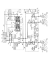
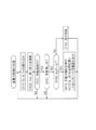
- FIG. 1 is an overall configuration diagram for describing an embodiment of a brake control device SC of a vehicle according to the present invention. It is a schematic diagram for explaining separation unit KB. It is a control flow figure for explaining the 1st processing example of pressure regulation control. It is a whole block diagram for demonstrating the 1st structural example of damping
- each of the four wheel cylinders are described as a right front wheel wheel cylinder CWi, a left front wheel wheel cylinder CWj, a right rear wheel wheel cylinder CWk, and a left rear wheel wheel cylinder CWl.
- the suffixes "i” to “k” at the end of the symbol may be omitted.
- each symbol represents a generic name for each of the four wheels. For example, "WH” represents each wheel, and "CW” represents each wheel cylinder.
- the subscripts “1” and “2” added at the end of various symbols are generic symbols indicating in which of two braking systems it relates. Specifically, “1” indicates the first system, and “2" indicates the second system. For example, in two master cylinder fluid passages, they are denoted as a first master cylinder fluid passage HM1 and a second master cylinder fluid passage HM2. Furthermore, the suffixes "1” and “2” at the end of the symbol may be omitted. When the subscripts “1” and “2” are omitted, each symbol represents a generic name of the two braking systems. For example, "VM” represents a master cylinder valve of each braking system.
- a braking control device SC According to the Present Invention
- An embodiment of a braking control device SC according to the present invention will be described with reference to the overall configuration diagram of FIG.
- a general vehicle a plurality of braking systems (for example, two systems) are adopted for fail safe, and redundancy is secured.
- the configuration of each braking system is the same, one braking system is shown as a representative.
- the vehicle is a hybrid vehicle or an electric vehicle equipped with an electric motor for driving.
- so-called regenerative coordination control coordination between a regenerative brake and a friction brake
- a vehicle provided with a braking control device SC is provided with a braking operation member BP, a wheel cylinder CW, a reservoir RV, a master cylinder CM, and a wheel speed sensor VW.
- the braking operation member (for example, a brake pedal) BP is a member operated by the driver to decelerate the vehicle. By operating the braking operation member BP, the braking torque of the wheel WH is adjusted, and a braking force is generated on the wheel WH.
- a rotating member for example, a brake disc
- a brake caliper is arrange
- the brake caliper is provided with a wheel cylinder CW.
- the pressure (braking fluid pressure) Pw of the braking fluid BF in the wheel cylinder CW is increased, the friction member (for example, the brake pad) is pressed against the rotating member KT. Since the rotating member KT and the wheel WH are fixed to rotate integrally, the friction force generated at this time generates a braking torque (frictional braking force) on the wheel WH.
- the reservoir (atmospheric pressure reservoir) RV is a tank for working fluid, in which the damping fluid BF is stored.
- the lower portion of the reservoir RV is partitioned by a partition plate SK into a master reservoir chamber Ru connected to the master cylinder chamber Rm and a pressure control reservoir chamber Rd connected to the pressure control unit KC.
- the damping fluid BF When the damping fluid BF is filled in the reservoir RV, the liquid surface of the damping fluid BF is above the height of the partition plate SK. Therefore, the damping fluid BF can freely move between the master reservoir chamber Ru and the pressure control reservoir chamber Rd beyond the partition plate SK.
- Master cylinder CM is mechanically connected to brake operation member BP via a brake rod or the like.
- the braking operation member BP When the braking operation member BP is not operated, the master cylinder CM and the reservoir RV are in communication.
- the brake operation member BP When the brake operation member BP is operated, the piston PS in the master cylinder CM is pushed, and the piston PS advances.
- master cylinder chamber Rm which is formed by the inner wall of master cylinder CM and piston PS, is shut off from reservoir RV (in particular, master reservoir chamber Ru).
- the operation of the braking operation member BP When the operation of the braking operation member BP is increased, the volume of the master cylinder chamber Rm decreases, and the braking fluid BF is pumped from the master cylinder CM toward the wheel cylinder CW.
- the case where the hydraulic pressure (braking hydraulic pressure) Pw of the wheel cylinder CW is adjusted (increased or decreased) by the master cylinder CM is referred to as "manual braking".
- the wheel cylinder CW is pressurized by the brake control device SC instead of the master cylinder CM.
- the braking control device SC is a so-called brake-by-wire configuration. That is, the wheel cylinder CW is pressurized by any one of the master cylinder CM and the braking control device SC.
- the case where the hydraulic pressure Pw of the wheel cylinder CW is adjusted (increased or decreased) by the braking control device SC is referred to as "controlled braking".
- Each wheel WH is provided with a wheel speed sensor VW so as to detect the wheel speed Vw.
- the signal of the wheel speed Vw is employed in anti-skid control or the like which suppresses the tendency of the wheel WH to lock.
- Each wheel speed Vw detected by the wheel speed sensor VW is input to the controller ECU.
- the controller ECU calculates a vehicle speed Vx based on the wheel speed Vw.
- the various fluid paths connecting the master cylinder CM, the wheel cylinder CW, the reservoir RV, and the braking control device SC will be described.
- the fluid path is a path for moving the braking fluid BF, which is a working fluid of the braking control device, and corresponds to a braking pipe, a flow path of a fluid unit, a hose or the like.
- upstream the side closer to the reservoir RV (the side farther from the wheel cylinder CW)
- the side closer to the wheel cylinder CW (the side farther from the reservoir RV) is It is called “downstream” or "lower.”
- Master cylinder fluid path HM is connected to master cylinder CM.
- the wheel cylinder fluid passage HW is connected to the wheel cylinder CW.
- One master cylinder chamber Rm of the master cylinder CM is fluidly connected to two wheel cylinders CW via fluid paths HM and HW. That is, the master cylinder fluid path HM is branched into the wheel cylinder fluid path HW at the branch portion Bw.
- the reservoir fluid path HR is connected to the pressure regulating reservoir chamber Rd of the reservoir RV.
- the return fluid path HS is connected to the master reservoir chamber Ru of the reservoir RV.
- the master cylinder CM, the wheel cylinder CW, and the fluid passages HM, HW, HR, and HS are filled with the damping fluid BF (that is, a fluid-tight state of the damping fluid BF is achieved).
- the braking control device SC includes an operation amount sensor BA, an operation switch ST, a stroke simulator SS, a simulator solenoid valve VS, a master cylinder solenoid valve VM, a controller ECU, a pressure control unit KC (electric pump DC, check valve GC, pressure control fluid It comprises a passage HC, a linear solenoid valve UC, an adjusted fluid pressure sensor PC), and a separation unit KB.
- the inside of the braking control device SC is also made liquid tight by the braking fluid BF.
- the brake operation member BP is provided with an operation amount sensor BA.
- the operation amount sensor BA detects the operation amount Ba of the braking operation member (brake pedal) BP by the driver.
- a hydraulic pressure sensor PM for detecting the pressure Pm of the master cylinder CM, an operation displacement sensor SP for detecting the operation displacement Sp of the braking operation member BP, and an operation force Fp of the braking operation member BP are detected as the braking operation amount sensor BA.
- At least one of the operating force sensors is employed. That is, of the hydraulic pressure (master cylinder hydraulic pressure) Pm in the master cylinder CM, the operation displacement Sp of the brake operation member BP, and the operation force Fp of the brake operation member BP as the brake operation amount Ba by the operation amount sensor BA. At least one of is detected.
- the braking operation amount Ba is input to the controller ECU.
- the braking operation member BP is provided with an operation switch ST.
- the operation switch ST detects the presence or absence of the operation of the braking operation member BP by the driver.
- the braking operation switch ST outputs an off signal as the operation signal St.
- an ON signal is output as the operation signal St.
- the braking operation signal St is input to the controller ECU.
- a stroke simulator (simply referred to as “simulator”) SS is provided to generate an operating force Fp on the brake operating member BP.
- a piston and an elastic body are provided inside the simulator SS.
- the braking fluid BF is moved from the master cylinder CM to the simulator SS, and the piston is pushed by the inflowing braking fluid BF.
- a force is applied to the piston by the elastic body in a direction to prevent the inflow of the braking fluid BF.
- the elastic body forms an operating force Fp when the brake operating member BP is operated.
- a simulator valve VS is provided between the master cylinder chamber Rm in the master cylinder CM and the simulator SS.
- the simulator valve VS is a two-position solenoid valve (also referred to as “on / off valve”) having an open position (communication state) and a closed position (shut off state).
- the simulator valve VS is controlled by the drive signal Vs from the controller ECU.
- the simulator valve VS is brought into the closed position, and the master cylinder CM and the simulator SS are in the disconnected state (disconnected state). In this case, the braking fluid BF from the master cylinder CM is not consumed by the simulator SS.
- the simulator valve VS At the time of control braking, the simulator valve VS is in the open position, and the master cylinder CM and the simulator SS are in communication. In this case, the operation characteristic (the relationship between the operation displacement Sp and the operation force Fp) of the braking operation member BP is formed by the simulator SS.
- the simulator valve VS employs a normally closed solenoid valve. When the volume of master cylinder chamber Rm is sufficiently large, simulator valve VS may be omitted.
- a master cylinder valve VM is provided in the middle of the master cylinder fluid path HM.
- the master cylinder valve VM is a two-position solenoid valve (on / off valve) having an open position (communication state) and a closed position (shut off state).
- Master cylinder valve VM is controlled by drive signal Vm from controller ECU.
- the master cylinder valve VM is in the open position, and the master cylinder CM and the wheel cylinder CW are in communication. In this case, the brake fluid pressure Pw is adjusted by the master cylinder CM.
- the master cylinder valve VM At the time of control braking, the master cylinder valve VM is in the closed position, and the master cylinder CM and the wheel cylinder CW are in the disconnected state (disconnected state). In this case, the brake fluid pressure Pw is controlled by the brake control device SC (in particular, the pressure control unit KC).
- the master cylinder valve VM employs a normally open solenoid valve.
- An electronic control unit also referred to as a "controller” ECU is configured of an electric circuit board on which a microprocessor MP or the like is mounted, and a control algorithm programmed in the microprocessor MP.
- the electric motor MC and the various solenoid valves VM, VS, UC (or UD) are controlled by the controller ECU based on the braking operation amount Ba, the operation signal St, and the adjusted hydraulic pressure Pc.
- drive signals Vm, Vs, Uc (or Ud) for controlling various solenoid valves VM, VS, UC (or UD) are calculated based on a control algorithm in the microprocessor MP. .
- a drive signal Mc for controlling the electric motor MC is calculated. Then, based on these drive signals Vm, Vs, Uc (or Ud), Mc, the solenoid valves VM, VS, UC (or UD), and the electric motor MC are driven.
- the controller ECU is connected to an electronic control unit (controller) of another system via a network via the in-vehicle communication bus BS.
- the amount of regeneration Rg is transmitted from the drive controller to the controller ECU so as to execute the regeneration coordination control.
- the “regeneration amount Rg” is a state amount representing the size of the regenerative brake generated by the drive motor. Electric power is supplied to the controller ECU from the on-board generator AL and the storage battery BT.
- the controller ECU is provided with a drive circuit DR to drive the solenoid valves VM, VS, UC (or UD), and the electric motor MC.
- a bridge circuit is formed by switching elements (power semiconductor devices such as MOS-FETs and IGBTs) so as to drive the electric motor MC.
- the energization state of each switching element is controlled based on the motor drive signal Mc, and the output of the electric motor MC is controlled.
- the excitation states thereof are controlled based on the drive signals Vm, Vs, Uc (or Ud) so as to drive the solenoid valves VM, VS, UC (or UD).
- the pressure control unit KC includes an electric pump DC, a pressure control fluid path HC, a check valve GC, a solenoid valve UC, and a control hydraulic pressure sensor PC.
- the electric pump DC is configured by a set of one electric motor MC and one fluid pump QC.
- the electric motor MC and the fluid pump QC are fixed so that the electric motor MC and the fluid pump QC rotate integrally.
- the electric pump DC (in particular, the electric motor MC) is a power source for increasing the braking fluid pressure Pw at the time of control braking.
- the electric motor MC is controlled by a controller ECU.
- a three-phase brushless motor is employed as the electric motor MC.
- the brushless motor MC is provided with a rotation angle sensor KA for detecting the rotor position (rotation angle) Ka.
- the switching elements of the bridge circuit are controlled based on the rotation angle (actual value) Ka, and the electric motor MC is driven. That is, the direction (that is, the excitation direction) of the energization amounts of the coils of each of the three phases (U phase, V phase, and W phase) is sequentially switched, and the brushless motor MC is rotationally driven.
- the drive circuit DR is provided with an energization amount sensor that detects an actual energization amount Ia (a generic name of each phase) of the electric motor MC.
- a current sensor is provided as an energization amount sensor, and a current Ia supplied to the electric motor MC is detected.
- a reservoir fluid passage HR is connected to the suction port Qs of the fluid pump QC. Further, a pressure control fluid passage HC is connected to the discharge port Qt of the fluid pump QC.
- the electric pump DC in particular, the fluid pump QC
- the braking fluid BF is sucked from the reservoir fluid passage HR through the suction port Qs and is discharged from the discharge port Qt to the pressure regulating fluid passage HC.
- a gear pump is employed as the fluid pump QC.
- a check valve GC (also referred to as a "check valve”) is interposed in the pressure control fluid passage HC.
- a check valve GC is provided near the discharge portion Qt of the fluid pump QC.
- the braking fluid BF can move from the reservoir fluid passage HR to the pressure regulating fluid passage HC, but moves from the pressure regulating fluid passage HC to the reservoir fluid passage HR (ie, braking) Backflow of fluid BF is prevented. That is, the electric pump DC is rotated only in one direction.
- the solenoid valve UC is connected to the pressure control fluid passage HC and the reservoir fluid passage HR.
- the solenoid valve UC is a linear solenoid valve (also referred to as a “proportional valve” or “differential pressure valve”) in which the valve opening amount (lift amount) is continuously controlled based on an energized state (for example, supplied current). It is.
- the solenoid valve UC is controlled by the controller ECU based on the drive signal Uc.
- a normally open solenoid valve is employed as the solenoid valve UC.
- the braking fluid BF is pumped from the reservoir fluid passage HR through the suction port Qs of the fluid pump QC and discharged from the discharge port Qt. Then, the damping fluid BF passes through the check valve GC and the solenoid valve UC and is returned to the reservoir fluid path HR.
- the reservoir fluid passage HR and the pressure regulating fluid passage HC form a reflux passage (a fluid passage in which the flow of the braking fluid BF returns to the original flow again), and a check valve GC is formed in the reflux passage.
- a solenoid valve UC is interposed.
- the braking fluid BF is recirculated in the order of “HR ⁇ QC (Qs ⁇ Qt) ⁇ GC ⁇ UC ⁇ HR” as indicated by the broken arrow (A).
- the solenoid valve UC When the solenoid valve UC is fully open (during non-energization because it is a normally open type), the hydraulic pressure (adjusted hydraulic pressure) Pc in the pressure control fluid passage HC is low and substantially “0 (atmospheric pressure)" .
- the adjusted fluid pressure Pc is increased.
- an adjusted hydraulic pressure sensor PC is provided in the pressure control fluid path HC (particularly, between the check valve GC and the solenoid valve UC).
- the electric pump DC is rotationally driven based on the operation amount Ba, the regeneration amount Rg, and a preset characteristic (calculation map). Then, based on the detection result (adjusted hydraulic pressure Pc) of the adjusted hydraulic pressure sensor PC, the solenoid valve UC is controlled to adjust the hydraulic pressure Pc in the pressure adjusting fluid passage HC. Specifically, the rotational speed Na of the electric pump DC (in particular, the electric motor MC) is controlled so that the target hydraulic pressure Pt is achieved, and the flow of the braking fluid BF from the electric pump DC (in particular, the fluid pump QC) (Flow rate) is generated. The solenoid valve UC throttles the flow of the braking fluid BF to finally achieve the target fluid pressure Pt. That is, the adjustment hydraulic pressure Pc is adjusted by the orifice effect of the solenoid valve UC.
- a separation unit KB is provided between the pressure control unit KC and the wheel cylinder CW.
- the pressure control unit KC (in particular, the pressure control fluid path HC) and the wheel cylinder CW (in particular, the pressurized fluid path HK) are fluidly separated by the separation unit KB.
- “fluid separation” is a state in which pressure is transmitted but movement of the damping fluid BF does not occur.
- the separation unit KB is composed of a separation cylinder CB and a separation piston PB, and the inside of the separation cylinder CB is divided into two chambers Ra and Rb by the separation piston PB.
- the pressurizing chamber Ra which is one chamber
- the separation chamber Rb which is the other chamber
- the pressurizing chamber Ra which is one chamber
- the separation chamber Rb which is the other chamber
- the pressurizing chamber Ra is fluidly connected to the pressurizing fluid passage HK.
- the pressurized fluid passage HK is connected to the master cylinder fluid passage HM and finally to the wheel cylinder CW.
- the separation chamber Rb is fluidly connected to the pressure control fluid passage HC.
- the pressure regulation fluid path HC is pressurized by the pressure regulation unit KC (that is, the electric pump DC and the solenoid valve UC).
- the fluid pressure Pa in the pressurizing chamber Ra is increased by the fluid pressure Pb
- the braking fluid pressure Pw is increased.
- the fluid pressure generated by the pressure regulation unit KC is transmitted in the order of Pc ⁇ Pb ⁇ Pa ⁇ Pw.
- the adjustment hydraulic pressure Pc is decreased, the braking hydraulic pressure Pw is decreased, contrary to the case of pressurization.
- the actual flow (movement) of the damping fluid BF is separated by the separating piston PB.
- the separation unit KB includes a separation cylinder CB, a separation piston PB, and a separation elastic body SB.
- the separation cylinder CB is a cylinder member having a bottom.
- the separation piston PB is a piston member inserted inside the separation cylinder CB.
- a groove is formed in the inner circumferential portion Bc of the separation cylinder CB, and two seals SL are fitted in the groove.
- An outer peripheral portion (an outer peripheral cylindrical surface) Bp of the separation piston PB and an inner peripheral portion (an inner peripheral cylindrical surface) Bc of the separation cylinder CB are sealed by the two seals SL.
- the separation piston PB can move smoothly along the central axis Jb of the separation cylinder CB.
- the inside of the separation cylinder CB is separated into two chambers Ra, Rb by a separation piston PB.
- the pressure chamber Ra is a hydraulic pressure chamber divided by the inner peripheral portion Bc of the separation cylinder CB, the first bottom portion (bottom surface) Bu, and the first end portion Br of the separation piston PB.
- a pressurizing fluid passage HK is connected to the pressurizing chamber Ra, and finally fluidly connected to the wheel cylinder CW.
- the two seals SL for example, a cup seal
- it is in communication with the master reservoir chamber Ru of the reservoir RV via the return fluid path HS.
- the fluid pressure between the two seals SL becomes “0 (atmospheric pressure)” (that is, no back pressure is generated).
- the return fluid path HS may be omitted.
- a cup seal that can be sucked from the back surface (that can absorb the damping fluid BF in the case of a negative pressure and relieve the negative pressure) may be used.
- the separation chamber Rb is a hydraulic pressure chamber divided by the inner peripheral portion Bc, the second bottom portion (bottom surface) Bt of the separation cylinder CB, and the second end Bq of the separation piston PB.
- the pressure chamber Ra and the separation chamber Rb are formed opposite to each other so as to sandwich the separation piston PB.
- the separation chamber Rb is located on the opposite side to the pressure chamber Ra with respect to the separation piston PB.
- a pressure control fluid passage HC is connected to the separation chamber Rb. Therefore, the pressure Pc adjusted by the pressure control unit KC is introduced into the separation chamber Rb.
- the separation unit KB and the pressure control unit KC are connected by the pressure control fluid path HC, so the structure is simplified, and the arrangement of the separation unit KB and the pressure control unit KC is highly flexible. That is, the mountability to a vehicle is improved.
- a separation elastic body (for example, a compression spring) SB is provided between the first bottom Bu of the separation cylinder CB and the separation piston PB.
- the separation elastic body SB presses the separation piston PB against the second bottom Bt of the separation cylinder CB in the direction of the central axis Jb of the separation cylinder CB.
- the second end Bq and the second bottom Bt are in contact with each other.
- the position of the separation piston PB in this state is called "initial position".
- the hydraulic pressure Pb the separation piston PB is moved along the central axis Jb in the forward direction (the left direction in the figure, which is the increasing direction of the braking hydraulic pressure Pw) Dp.
- the volume of the pressure chamber Ra decreases, and the braking fluid BF in the pressure chamber Ra is pumped to the pressure fluid passage HK. Then, the braking fluid pressure Pw of the wheel cylinder CW is increased.
- the separation piston PB is reliably returned to the position (initial position) in contact with the second bottom Bt of the separation cylinder CB by the elastic force of the compression spring SB. As a result, the hydraulic pressure Pa in the pressure chamber Ra is returned to “0”.
- the hydraulic pressure Pa of the pressure chamber Ra does not increase even when the separation piston PB advances, and remains "0". If the pressure chamber hydraulic pressure Pa does not increase, the separation piston PB continues to move forward and is eventually moved until the first end Br of the separation piston PB abuts on the first bottom Bu of the separation cylinder CB . Therefore, the movable range of the separation piston PB is limited to the predetermined distance lp (displacement from the initial position to the contact position).
- the pressure control unit KC and the wheel cylinder CW are fluidly separated by the separation unit KB, and the braking fluid BF is not moved between the pressure control unit KC and the wheel cylinder CW.
- the fluid separation in which the pressure is transmitted but the movement of the damping fluid BF does not occur limits the amount (the volume corresponding to the predetermined distance lp) of the damping fluid BF lost due to the failure.
- a first processing example of pressure regulation control will be described with reference to the control flowchart of FIG. 3.
- the "pressure control control” is drive control of the electric motor MC and the solenoid valve UC for adjusting the adjusted hydraulic pressure Pc.
- the control algorithm is programmed in the controller ECU.
- step S110 the braking operation amount Ba, the operation signal St, the adjustment hydraulic pressure Pc, the rotation angle Ka, and the regeneration amount Rg are read.
- the operation amount Ba is detected by an operation amount sensor BA (for example, a master cylinder hydraulic pressure sensor PM, an operation displacement sensor SP).
- the operation signal St is detected by an operation switch ST provided on the braking operation member BP.
- the adjusted hydraulic pressure Pc is detected by an adjusted hydraulic pressure sensor PC provided in the pressure control fluid passage HC.
- the rotation angle Ka is detected by a rotation angle sensor KA provided to the electric motor MC.
- the regeneration amount Rg is transmitted from the drive controller via the communication bus BS.
- step S120 it is determined whether or not the braking operation is in progress based on at least one of the braking operation amount Ba and the braking operation signal St. For example, if the operation amount Ba is equal to or larger than the predetermined value bo, step S120 is affirmed, and the process proceeds to step S130. On the other hand, if “Ba ⁇ bo”, step S120 is denied, and the process returns to step S110.
- the predetermined value bo is a preset constant corresponding to the play of the braking operation member BP. If the operation signal St is on, the process proceeds to step S130. If the operation signal St is off, the process returns to step S110.
- step S130 the normally open master cylinder valve VM is brought into the closed position, and the normally closed simulator valve VS is brought into the open position. That is, when step S120 is satisfied for the first time, the manual braking in which the braking hydraulic pressure Pw is generated by the master cylinder CM is switched to the control braking in which the braking hydraulic pressure Pw is generated by the braking control device SC.
- step S140 the required fluid pressure Pr is calculated based on the operation amount Ba.
- the required fluid pressure Pr is a target value of the adjusted fluid pressure Pc, and is a value corresponding to the deceleration of the vehicle.
- the required hydraulic pressure Pr is determined to be “0” in the range of “0” to a predetermined value bo according to the calculation map Zpr, and the manipulation amount Ba increases when the operation amount Ba is equal to or more than the predetermined value bo Along with this, it is calculated so as to monotonically increase from "0".
- a target fluid pressure Pt is calculated based on the required fluid pressure Pr and the regeneration amount Rg.
- the “regeneration amount Rg” is a regenerative brake amount generated by the drive motor. Regeneration amount Rg is converted to a dimension of hydraulic pressure to calculate regenerative hydraulic pressure Pg.
- the target fluid pressure Pt is a fluid pressure target value to be achieved by the friction brake.
- a target rotational speed Nt is calculated based on the target fluid pressure Pt.
- the target rotation speed Nt is a target value of the rotation speed of the electric motor MC.
- the target rotation speed Nt is determined to be the predetermined rotation speed no in the range of the target fluid pressure Pt from "0" to the predetermined value po according to the calculation map Znt, and the target fluid pressure Pt is determined when the target fluid pressure Pt is the predetermined value po or more. Is calculated so as to monotonically increase from the predetermined number of revolutions no as the As described above, the adjusted hydraulic pressure Pc is generated by the orifice effect of the solenoid valve UC. In order to obtain an orifice effect, a certain amount of flow rate is required.
- the target rotational speed Nt is the minimum required for fluid pressure generation.
- the value (a preset constant) is determined to no.
- the target rotation speed Nt may be directly calculated based on the braking operation amount Ba. In any case, the target rotational speed Nt is determined based on the braking operation amount Ba.
- step S170 a rotational speed (rotational speed per unit time) Na is calculated based on the rotational angle (detection value) Ka. Specifically, the rotation angle Ka is time-differentiated to calculate the actual rotation number Na.
- step S180 rotation speed feedback control of the electric motor MC is performed based on the target rotation speed Nt and the actual rotation speed Na.
- the number of rotations of the electric motor MC is used as a control variable, and the amount of energization (for example, supply current) to the electric motor MC is controlled.
- the rotational speed deviation hN becomes "0" (that is, the actual value Na is the target value Nt )
- the amount of energization of the electric motor MC is finely adjusted.
- nx the amount of energization to the electric motor MC is increased, and the electric motor MC is accelerated.
- the predetermined value nx is a constant set in advance.
- step S190 hydraulic pressure feedback control of the solenoid valve UC is executed based on the target hydraulic pressure Pt and the adjusted hydraulic pressure Pc.
- the pressure of the braking fluid BF in the pressure control fluid passage HC is used as a control variable to control the amount of current supplied to the normally open linear solenoid valve UC.
- the hydraulic pressure deviation hP becomes "0" (that is, the adjusted hydraulic pressure Pc is the target hydraulic pressure
- the amount of energization of the solenoid valve UC is finely adjusted (to approach Pt).
- the predetermined value px is a constant set in advance.
- the electric pump DC as a pressure source is rotated, and the braking fluid BF is returned in the reservoir fluid passage HR and the pressure adjustment fluid passage HC (that is, when the adjusted fluid pressure Pc is generated). (Always, the electric pump DC is rotated). Then, the amount of current supplied to the solenoid valve UC (supply current) is controlled to adjust the fluid pressure in the pressure control fluid passage HC.
- the base pressure underlying pressure regulation by the solenoid valve UC is the high pressure accumulated in the accumulator. If the high pressure is regulated by the solenoid valve UC, pressure regulation accuracy at the low pressure is concerned.
- the electric pump DC is employed as the pressure source, the source pressure is raised from "0" at the start of braking. Since the pressure adjustment unit KC using the electric pump DC is employed, control accuracy in the low pressure region can be appropriately secured.
- a first configuration example of the braking control device SC in which two fluid paths are formed will be described with reference to the overall configuration diagram of FIG. 4.
- the first system (system related to the first master cylinder chamber Rm1) of the two fluid paths is fluidly connected to the wheel cylinder CWi of the right front wheel WHi and the wheel cylinder CWl of the left rear wheel WHl.
- the second system (system related to the second master cylinder chamber Rm2) of the two fluid paths is fluidly connected to the wheel cylinder CWj of the left front wheel WHj and the wheel cylinder CWk of the right rear wheel WHk.
- diagonal type also referred to as X type
- H type the thing of order order
- front wheel wheel cylinders CWi and CWj are connected to the first system
- rear wheel wheel cylinders CWk and CWl are connected to the second system.
- the braking device includes an upper fluid unit HU closer to the master cylinder CM and a lower fluid unit HL closer to the wheel cylinder CW.
- the upper fluid unit HU is a fluid unit controlled by the upper controller ECU and including the braking control device SC.
- the lower fluid unit HL is a fluid unit that is controlled by the lower controller ECL and performs antiskid control, vehicle stabilization control, and the like.
- the upper controller ECU and the lower controller ECL are connected in a communicable state by the communication bus BS, and the sensor signal and the calculated value are shared.
- the master cylinder CM is a tandem type, and the inside is divided into first and second master cylinder chambers Rm1 and Rm2 by the first and second master pistons PS1 and PS2.
- the inside of the atmospheric pressure reservoir RV is divided into three parts by a partition plate SK.
- the first master reservoir chamber Ru1 is connected to the first master cylinder chamber Rm1
- the second master reservoir chamber Ru2 is connected to the second master cylinder chamber Rm2.
- the pressure control reservoir chamber Rd is fluidly connected to the pressure control unit KC by a reservoir fluid passage HR.
- First and second master cylinder fluid passages HM1 and HM2 are connected to the first and second master cylinder chambers Rm1 and Rm2.
- First and second master cylinder valves VM1 and VM2 are interposed in the first and second master cylinder fluid passages HM1 and HM2.
- the first and second master cylinder valves VM1 and VM2 employ normally open solenoid valves (on / off type).
- the simulator SS In order to generate the operation force Fp of the braking operation member BP when the first and second master cylinder valves VM1 and VM2 are closed (during control braking) at the outlet of the second master cylinder chamber Rm2, the simulator SS Provided. Normally closed simulator valve VS (ON / OFF) so that the braking fluid BF is not consumed by the simulator SS when the first and second master cylinder valves VM1 and VM2 are opened (during manual braking) A mold is provided between the second master cylinder fluid path HM2 and the simulator SS. The simulator valve VS can be omitted.
- a series arrangement type is adopted as the separation unit KB.
- two separation pistons PB1, PB2 are arranged coaxially with the central axis Jb of the separation cylinder CB.
- the outer periphery of the second separation piston PB2 and the inner periphery of the separation cylinder CB are sealed by a seal SL, and one side bottom of the separation cylinder CB, the inner periphery of the separation cylinder CB, and the second separation piston PB2
- the second pressure chamber Ra2 is formed by the one side end of the second pressure chamber Ra2.
- first separation piston PB1 and the inner periphery of the separation cylinder CB are sealed by a seal SL, and the other end of the second separation piston PB2, the inner periphery of the separation cylinder CB, and A first pressure chamber Ra1 is formed by one end of the first separation piston PB1.
- a separation chamber Rb is formed by the other end of the first separation piston PB1, the inner peripheral portion of the separation cylinder CB, and the other side bottom of the separation cylinder CB. In the center axis Jb, the separation chamber Rb is located on the opposite side of the first and second pressure chambers Ra1 and Ra2 with respect to the first and second separation pistons PB1 and PB2.
- the first and second separation pistons PB1 and PB2 are shown in the initial position (rightward in the figure) by the first and second separation elastic bodies (compression springs) SB1 and SB2. The position is most pressed in the reverse direction Dq). Further, the first and second sets of seals are communicated with the first and second master reservoir chambers Ru1 and Ru2 of the reservoir RV via the first and second return fluid passages HS1 and HS2, respectively. ing. The first and second return fluid paths HS1 and HS2 can be omitted.
- a reservoir fluid path HR is provided to connect the pressure regulating reservoir chamber Rd of the reservoir RV, the suction portion Qs of the fluid pump QC, and the solenoid valve UC.
- a pressure control fluid passage HC is provided to connect the discharge portion Qt of the fluid pump QC and the solenoid valve UC. That is, the reservoir fluid passage HR and the pressure regulating fluid passage HC constitute a return passage including the suction port Qs and the discharge port Qt. And, a normally open and linear type solenoid valve UC is provided so as to be interposed in the return flow path.
- the controller ECU brings the first and second master cylinder valves VM1 and VM2 into the closed position, and brings the simulator valve VS into the open position. Then, one electric pump DC and one electromagnetic valve UC that constitute the pressure adjustment unit KC are driven by the controller ECU based on the operation amount Ba. Specifically, when the electric pump DC is rotated, the braking fluid BF is pumped from the reservoir fluid passage HR to the pressure regulating fluid passage HC. That is, a flow of the braking fluid BF according to the rotation of the electric pump DC is generated in the pressure control fluid passage HC. A check valve GC is provided in the pressure control fluid passage HC so that the braking fluid BF does not reversely flow.
- the solenoid valve UC When the electric pump DC is driven, the solenoid valve UC is controlled to achieve the target fluid pressure Pt determined based on the operation amount Ba.
- the solenoid valve UC throttles the flow (reflux) of the braking fluid BF, and an orifice effect at this time generates a regulated fluid pressure Pc in the pressure regulating fluid passage HC.
- an adjustment hydraulic pressure sensor PC for detecting an adjustment hydraulic pressure Pc is provided in a pressure adjustment fluid passage HC between the check valve GC and the solenoid valve UC, and a detection result (actual adjustment hydraulic pressure) Pc is a target
- the energization state of the solenoid valve UC is controlled to coincide with the fluid pressure Pt.
- the pressure control fluid passage HC is fluidly connected to the separation chamber Rb of the separation unit KB between the check valve GC and the solenoid valve UC. Therefore, the adjusted hydraulic pressure Pc generated by the pressure control unit KC is introduced into the separation chamber Rb. Thereby, the first separation piston PB1 is moved in the forward direction Dp (movement to the left in the drawing). By the advancement of the first separation piston PB1 via the first separation elastic body SB1, the second separation piston PB2 is moved in the forward direction Dp. When the first and second separation pistons PB1 and PB2 move forward, the fluid pressures Pa1 and Pa2 in the first and second pressure chambers Ra1 and Ra2 are increased.
- the first and second pressure chambers Ra1 and Ra2 are fluidly connected to the first and second master cylinder fluid paths HM1 and HM2 via the pressurized fluid paths HK1 and HK2. Therefore, as the fluid pressures Pa1 and Pa2 in the first and second pressure chambers Ra1 and Ra2 are increased, the braking fluid pressures Pwi to Pwl in the wheel cylinders CWi to CWl are increased.
- the fluid unit HU may be included and integrally configured. Furthermore, the upper fluid unit HU may be configured to include a controller ECU. The upper fluid unit HU is connected to the wheel cylinder CW via a lower fluid unit HL (including a controller ECL). The lower fluid unit HL is a known fluid unit for performing antiskid control, vehicle stabilization control, and the like. The controller ECU of the upper fluid unit HU and the controller ECL of the lower fluid unit HL are connected by the communication bus BS, and information sharing is performed.
- the lower fluid unit HL is provided with first and second fluid pumps QL1 and QL2 which are driven by the electric motor ML and pump up the braking fluid BF from the first and second low pressure reservoirs RL1 and RL2.
- the first and second master cylinder fluid passages HM1 and HM2 are provided with normally open first and second charge over valves VN1 and VN2, respectively.
- First and second input hydraulic pressure sensors PN1 and PN2 are provided to detect first and second input hydraulic pressures Pn1 and Pn2 to the first and second charge over valves VN1 and VN2, respectively. Note that any one of the two input hydraulic pressure sensors PN1 and PN2 can be omitted.
- the hydraulic pressure generated by the first and second fluid pumps QL1 and QL2 is adjusted by the first and second charge over valves VN1 and VN2, and the downstream side of the first and second charge over valves VN1 and VN2 (wheel cylinder The fluid pressure near the CW is increased.
- the first and second master cylinder fluid passages HM1 and HM2 at the first and second branch portions Bw1 and Bw2 between the first and second charge over valves VN1 and VN2 and the wheel cylinders CW are wheel cylinders It branches into fluid paths HWi to HWl.
- a normally open inlet valve VIi is interposed in the right front wheel wheel cylinder fluid passage HWi (a fluid passage connecting the branch portion Bw1 and the right front wheel wheel cylinder CWi).
- the wheel cylinder fluid passage HWi is fluidly connected to the low pressure reservoir RL1 via the normally closed outlet valve VOi.
- the inlet valve VIi in order to reduce the hydraulic pressure Pwi in the wheel cylinder CWi, the inlet valve VIi is brought into the closed position and the outlet valve VOi is brought into the open position.
- the brake fluid BF in the wheel cylinder CWi is moved to the low pressure reservoir RL1, and the brake fluid pressure Pwi is decreased. Further, in order to increase the braking fluid pressure Pwi, the inlet valve VIi is brought into the open position, and the outlet valve VOi is brought into the closed position. The hydraulic pressure via the charge over valve VN1 is introduced into the wheel cylinder CWi, and the braking hydraulic pressure Pwi is increased.
- the separation unit KB and the pressure control unit KC are connected through the pressure control fluid path HC, so installation in a vehicle can be facilitated with a simple structure.
- the displacement in the movable central axis Jb direction of the first and second separation pistons PB1, PB2 is geometrically limited in terms of construction. For this reason, even if a failure occurs in the fluid passage, the amount of the damping fluid BF that flows out of the braking device is limited. As a result, the fail-safety of the braking device is improved.
- a second configuration example of the braking control device SC in which two fluid paths are formed will be described with reference to the schematic view of FIG. 5.
- the separation unit KB a series arrangement type in which the first and second separation pistons PB1, PB2 are arranged on the coaxial Jb is adopted.
- a parallel arrangement type separation unit KB in which the central axis Jb1 of the first separation cylinder CB1 and the central axis Jb2 of the second separation cylinder CB2 are separate axes is employed.
- pressure regulation is performed by the normally open solenoid valve UC
- pressure regulation is performed by the normally closed solenoid valve UD.
- the two separation units KB1 and KB2 are connected to the first and second master cylinder fluid passages HM1 via the first and second pressurized fluid passages HK1 and HK2, respectively. , HM2 fluidly connected.
- the first and second separation chambers Rb1 and Rb2 are the first and second pressure chambers with respect to the first and second separation pistons PB1 and PB2, respectively. Located opposite Ra1 and Ra2.
- the reservoir fluid passage HR is connected to the suction port Qs of one fluid pump QC forming the electric pump DC, and the pressure regulating fluid passage HC is connected to the discharge port Qt of the fluid pump QC.
- the pressure control fluid passage HC is provided with one check valve GC and one solenoid valve UD.
- the outlet of the normally closed linear solenoid valve UD is connected to the reservoir fluid passage HR.
- the pressure control fluid passage HC is branched into first and second pressure control fluid passages HC1 and HC2 at a branch portion Bn.
- the first and second pressure control fluid passages HC1 and HC2 are connected to the first and second separation chambers Rb1 and Rb2 of the first and second separation units KB1 and KB2, respectively.
- the branch portion Bn is located between the check valve GC and the solenoid valve UD.
- the hydraulic pressure Pc in the pressure control fluid passage HC is introduced into the first and second separation chambers Rb1 and Rb2 through the first and second pressure control fluid passages HC1 and HC2.
- the adjusted hydraulic pressure Pc formed by the pressure adjustment unit KC including the solenoid valve UD is introduced to the first and second separation units KB1 and KB2, and the brake hydraulic pressure Pw is adjusted.
- the solenoid valve UD is a linear solenoid valve in which the valve opening amount (lift amount) is continuously controlled based on the energized state (for example, supplied current). Since the solenoid valve UD is a normally closed type, the valve opening amount is increased as the amount of energization is increased. Pressure adjustment control (second processing example) based on the solenoid valve UD will be described later.
- the structure is simple and the arrangement is the same as above. High degree of freedom is secured. Further, since the pressure control unit KC and the wheel cylinder CW are fluidically separated by the first and second separation units KB1 and KB2 (particularly, the first and second separation pistons PB1 and PB2), the braking device Fail-safety can be improved.
- the series arrangement type separation unit KB is adopted, a dynamic hydraulic pressure difference may occur between the first braking system and the second braking system, but the separation arrangement of the parallel arrangement type By adopting the unit KB, the fluid pressure difference can be eliminated.
- the solenoid valve UD since the normally closed solenoid valve UD is adopted, there may occur a case where the hydraulic pressure remains in the separation chambers Rb1 and Rb2 after the end of the braking operation. Therefore, at the end of braking, the solenoid valve UD is once brought into the open position, and the residual pressure can be released. Also in the second configuration example, the first and second return fluid paths HS1 and HS2 can be omitted.
- step S210 corresponds to the processes from step S110 to step S150, and therefore will be briefly described.
- step S210 the operation amount Ba, the operation signal St, the adjustment hydraulic pressure Pc, the rotation angle Ka, and the regeneration amount Rg (the size of the regenerative brake) are read.
- step S220 it is determined whether or not the braking operation is in progress. If the braking operation is in progress, the process proceeds to step S230. If the braking operation is not in progress, the process returns to step S210.
- step S230 the normally open master cylinder valve VM is brought into the closed position, and the normally closed simulator valve VS is brought into the open position.
- step S240 based on the operation amount Ba and the operation map Zpr, in the range of the operation amount Ba from “0" to the predetermined value bo, the required hydraulic pressure Pr is calculated to "0", and the operation amount Ba is predetermined. Above the value bo, the required hydraulic pressure Pr is calculated so as to monotonously increase from "0" according to the increase of the operation amount Ba.
- step S270 it is determined based on the hydraulic pressure deviation hP whether "the hydraulic pressure deviation hP is equal to or greater than a predetermined value pz".
- a predetermined value also referred to as a “pressure increase predetermined value”
- pz is a threshold value for determination, and is a preset constant larger than “0”. If “hP ⁇ pz” and step S270 is affirmative, the pressure increase mode is set as the control mode, and the process proceeds to step S290.
- the "pressure increase mode” is a mode in which the adjusted hydraulic pressure Pc is increased. On the other hand, if “hP ⁇ pz” and step S270 is negative, the process proceeds to step S280.
- step S280 it is determined based on the hydraulic pressure deviation hP whether "the hydraulic pressure deviation hP is equal to or greater than a predetermined value -pg".
- a predetermined value also referred to as “predetermined pressure reduction value”
- ⁇ pg is a threshold for determination, and is a constant set in advance and less than “0”. If “hP ⁇ ⁇ pg” and step S280 is affirmative, the holding mode is set as the control mode, and the process proceeds to step S300. On the other hand, when “hP ⁇ pg” and step S280 is negative, the pressure reduction mode is set as the control mode, and the process proceeds to step S310.
- the "holding mode” is a mode in which the adjusted hydraulic pressure Pc is maintained constant
- the "pressure reduction mode” is a mode in which the adjusted hydraulic pressure Pc is decreased.
- step S290 processing in the pressure increase mode is performed.
- the normally closed solenoid valve UD is maintained in the closed position.
- the electric pump DC in particular, the electric motor MC
- the braking fluid BF is moved from the reservoir fluid passage HR into the pressure regulating fluid passage HC, and the adjusted fluid pressure Pc is increased.
- a target value (target energization amount) It of the energization amount of the electric motor MC is determined according to the hydraulic pressure deviation hP.
- the actual energization amount Ia is controlled to be equal to the target energization amount It.
- step S300 processing of the holding mode is performed.
- the solenoid valve UD is maintained in the closed position, and the rotation of the electric motor MC is stopped.
- the adjusted hydraulic pressure Pc in the pressure regulating fluid passage HC is contained by the check valve GC and the solenoid valve UD (that is, the braking fluid BF is pressure regulated It can not move to the outside of the fluid passage HC). For this reason, the amount of energization to the electric motor MC can be reduced toward a predetermined value including "0 (energization stop)".
- step S310 the process in the pressure reduction mode is performed.
- step S310 the amount of energization of the solenoid valve UD is adjusted based on the drive signal Ud determined by the controller ECU, and the amount of valve opening (lift) is controlled. Since the braking fluid BF is moved from the pressure control fluid passage HC to the reservoir fluid passage HR via the solenoid valve UD, the adjusted fluid pressure Pc is reduced. At this time, the rotational movement of the electric motor MC is stopped. Similar to the holding mode, the amount of energization of the electric motor MC can be decreased toward a predetermined value including "0 (energization stop)".
- the electric pump DC is driven to rotate constantly during braking control.
- the rotation of the electric pump DC is stopped in the holding of the adjusted hydraulic pressure Pc and in the pressure reduction mode.
- the amount of power supplied to the electric motor MC can be reduced by the check valve GC, so that power saving of the braking control device SC can be achieved.
- the process of power saving control will be described with reference to the control flowchart of FIG. 7.
- the braking control device SC the most power is consumed when waiting for a signal or the like to maintain the stopped state of the vehicle. For example, in a vehicle equipped with an automatic transmission, even if the accelerator pedal is not operated, the vehicle tries to move forward by the idling state of the engine (so-called creep phenomenon). For this reason, in order to maintain the stopped state of the vehicle, the braking control device SC needs to keep applying the braking torque to the wheel WH.
- the “power saving control” is control to reduce the power consumption of the braking control device SC in such a situation.
- step S410 the operation amount Ba, the operation signal St, and the wheel speed Vw are read.
- the wheel speed Vw is detected by a wheel speed sensor VW provided on each wheel WH.
- step S420 the vehicle speed Vx is calculated based on the wheel speed Vw. For example, at the time of braking, the fastest one of the four wheel speeds Vw is calculated as the vehicle speed Vx. Further, at the time of non-braking including during acceleration of the vehicle, the slowest one of the four wheel speeds Vw is determined as the vehicle body speed Vx.
- the vehicle speed Vx may be calculated by the lower controller ECL and transmitted via the communication bus BS.
- step S430 based on at least one of the operation amount Ba and the operation signal St, it is determined whether or not the braking operation is in progress. If the braking operation is in progress, the process proceeds to step S440. If the braking operation is not in progress, the process returns to step S410.
- step S450 it is determined whether the operation amount Ba is constant or not based on the operation amount Ba. If the operation amount Ba is not constant, the process proceeds to step S460, and the above-described normal pressure regulation control (normal control) is performed. If the operation amount Ba is constant, the process proceeds to step S470.
- step S470 Power saving control is executed in step S470.
- the solenoid valve UC (or the solenoid valve UD) is brought to the fully closed position.
- the braking fluid BF between the check valve GC and the solenoid valve UC (or the solenoid valve UD) is contained, and the adjusted hydraulic pressure Pc is held constant.
- the solenoid valve UC (or the solenoid valve UD) is in the fully closed position, the amount of energization of the electric motor MC is decreased toward a predetermined value including “0 (deenergization)”.
- the electric motor MC can ensure the necessary and sufficient responsiveness of the adjusted hydraulic pressure Pc.
- the separation unit KB and the pressure control unit KC are connected by the fluid path HC, they have a simple structure and a high degree of freedom in layout.
- the pressure regulation unit KC and the wheel cylinder CW are fluidly separated by the separation unit KB so that the braking fluid BF is not moved between the pressure regulation unit KC and the wheel cylinder CW. For this reason, the fail-safety of the braking control device SC can be improved.
- the pressure regulation unit KC since the electric pump DC is adopted as the pressure source, the source pressure thereof is increased from “0”. Therefore, the pressure adjustment accuracy of the adjusted hydraulic pressure Pc can be suitably secured in the low pressure region.
- the power saving control reduces the amount of power supplied to the electric motor MC, so that power saving of the braking control device SC can be achieved.
- the separation unit KB shown in the first configuration example, the pressure regulation unit KC, and the separation unit KB shown in the second configuration example, and the pressure regulation unit KC can be combined.
- pressure adjustment unit KC including series arrangement type separation unit KB + solenoid valve UC
- pressure adjustment unit KC including parallel arrangement type separation unit KB + solenoid valve UC
- series arrangement type separation unit KB + solenoid valve UD
- pressure adjustment unit KC including UD and “pressure adjustment unit KC including parallel arrangement type separation unit KB + magnetic valve UD” may be employed. The same effect is obtained in any configuration.
- the vehicle is an electric vehicle or a hybrid vehicle having a drive motor.
- the linear solenoid valves UC and UD ones in which the valve opening amount is adjusted in accordance with the energization amount are adopted.
- the solenoid valves UC and UD are on / off valves, opening and closing of the valves may be controlled by a duty ratio and hydraulic pressure may be controlled linearly.
- the area in the pressure chamber Ra (referred to as “output pressure receiving area”) and the area in the separation chamber Rb (referred to as “input pressure receiving area”) are the same Exemplified.
- a separation piston PB having different input pressure receiving area and output pressure receiving area may be employed. That is, as the separation piston PB, a so-called stepped type having two different diameters may be employed.
- KC (HC) side diameter > “CW (HK) side diameter”
- the output pressure receiving area is smaller than the input pressure receiving area
- the pressure adjustment resolution of the braking fluid pressure Pw can be improved, and the required flow rate of the electric pump DC can be reduced.
- the configuration of the disk brake device has been exemplified.
- the friction member is a brake pad and the rotating member is a brake disc.
- a drum brake may be employed.
- a brake drum is employed instead of the caliper.
- the friction member is a brake shoe, and the rotating member is a brake drum.
- a brushless motor is employed as a drive source of the fluid pump QC.
- the electric motor MC a brushed motor (also simply referred to as a brush motor) may be employed instead of the brushless motor.
- an H bridge circuit formed of four switching elements (power transistors) is used as the bridge circuit.
- the electric motor MC is provided with the rotation angle sensor KA, and the drive circuit DR is provided with the energization amount sensor IA.
- the diagonal type fluid path is exemplified as the two-system fluid path.
- an anterior-posterior (also referred to as “H-type”) configuration may be employed.
- front wheel wheel cylinders CWi and CWj are fluidly connected to the first master cylinder fluid passage HM1 (that is, the first system).
- the second master cylinder fluid passage HM2 ie, the second system
- CWk, CWl is fluidly connected to the rear wheel wheel cylinders CWk, CWl.
Landscapes
- Engineering & Computer Science (AREA)
- Transportation (AREA)
- Mechanical Engineering (AREA)
- Regulating Braking Force (AREA)
- Braking Systems And Boosters (AREA)
- Valves And Accessory Devices For Braking Systems (AREA)
- Control Of Positive-Displacement Pumps (AREA)
Abstract
車輪に備えられたホイールシリンダCWの液圧Pwを調整する車両の制動制御装置であって、「電動ポンプDC、及び、電磁弁UC、UDにて構成され、電動ポンプDCと電磁弁UC、UDとの間の調圧流体路HCの液圧Pcを調整する調圧ユニットKC」と、調圧流体路HCの液圧Pcを検出する液圧センサPCと、「液圧センサPCの検出値Pcに基づいて、電動ポンプDC、及び、電磁弁UC、UDを制御するコントローラECU」と、「シリンダCB、及び、ピストンPBにて構成され、『ホイールシリンダCWに接続される加圧室Ra』、及び、『調圧流体路HCに接続され、ピストンBPに対して加圧室Raとは反対側に位置する分離室Rb』を有する分離ユニットKB」と、を備える。
Description
本発明は、車両の制動制御装置に関する。
特許文献1には、「電動モータでピストンを前進駆動して液圧室に液圧を発生させる電動シリンダにおいて、その液圧発生の応答性を高める」ことを目的に、「電動モータで、ボールねじ機構の雄ねじ部材を、その端面がハウジングの内壁面に当接する後退方向の限界位置まで移動させ、次に、前記限界位置において停止した電動モータの回転位置を記憶し、次に電動モータを前記記憶した回転位置から前進方向に予め設定した設定回転数だけ駆動することで、後部ピストンを入力ポートの直後の初期位置に位置決めする」ことが記載されている。
更に、特許文献1には、「スレーブシリンダのアクチュエータは、電動モータの出力軸に設けた駆動ベベルギヤと、駆動ベベルギヤに噛合する従動ベベルギヤと、従動ベベルギヤにより作動するボールねじ機構とを備える。電動モータを一方向に駆動すると、駆動ベベルギヤ、従動ベベルギヤおよびボールねじ機構を介して後部および前部ピストンが前進し、液路に連なる入力ポートが閉塞された瞬間に後部および前部液圧室にブレーキ液圧を発生させ、そのブレーキ液圧を、出力ポートを介して液路に出力することができる」旨が記載されている。
特許文献2には、「停止距離を短くして安全性を高める」ことを目的に、「車間距離と相対速度を検知する車間距離センサと車輪速センサ、ブレーキが操作されたことを検出するブレーキスイッチ、これらセンサの出力によって車間距離が所定距離以下又は相対速度が所定速度以上の状態でブレーキが操作されたことを知り、モータ及び電磁弁に信号を出力するコントロールユニット、該信号によって回転を開始してポンプを駆動しアキュムレータに蓄圧するモータ、同じく信号によって開弁する電磁弁、電磁弁が開弁するとアキュムレータの圧力により駆動されチェック弁を閉じるとともに油圧を発生し、該油圧をホイールシリンダに作用するピストンが設けられている」ことが記載されている。
更に、特許文献2には、「コントロールユニットから電磁弁に開弁信号を送り電磁弁を開弁する。電磁弁が駆動され開弁すると、シリンダ内のピストンの後方にアキュムレータの圧力が導かれ、ピストンが図で左側に移動し、シリンダ内の圧力が高まって、チェック弁を動かして、マスタシリンダとホイールシリンダとの連通を断つと同時に、ホイールシリンダの圧力を瞬時に高めブレーキを掛ける。このように車間距離が所定量以下又は相対速度が所定量以上になり運転者がブレーキペダルを踏むと、ブレーキ操作の早い時期、すなわち、ブレーキペダルストロークの初期に瞬時に強力なブレーキが作動する第2のブレーキ特性によってブレーキが掛かる」ことが記載されている。
特許文献1の装置では、電気モータの回転動力が、ベベルギヤ、及び、ボールねじによって、スレーブシリンダ内のピストンを前進させる動力に変換される。例えば、ボールねじは、スレーブシリンダの中心軸上に配置される必要がある。このように、機械的な動力伝達機構にて、電気モータの動力が、最終的には制動液の圧力(液圧)に変換される制動制御装置では、各構成要素の配置に制約が存在する。車両への搭載性において、装置配置の自由度が高いものが望まれている。
特許文献2の装置は車間距離制御装置であるため、ホイールシリンダの圧力を瞬時に高めることができるよう、シリンダ/ピストンが電磁弁に接続され、電磁弁によってアキュムレータとの接続が選択される。通常は、シリンダ/ピストンは、電磁弁を介して、リザーバに接続されている。しかし、「車間距離が所定量以下又は相対速度が所定量以上になり運転者がブレーキペダルを踏むと、ブレーキ操作の早い時期」に、シリンダ/ピストンは、電磁弁によって、リザーバに接続される。このような構成が、一般的な制動制御装置に適用されるためには、制動液が高精度で円滑に制御されることが必要である。
以上の点を鑑み、本発明の目的は、所謂、ブレーキ・バイ・ワイヤ構成の車両の制動制御装置において、構造が簡素であり、配置の自由度が高く、信頼度が向上され得るものを提供することである。
本発明に係る車両の制動制御装置は、車両の車輪(WH)に備えられたホイールシリンダ(CW)の液圧(Pw)を調整するものであって、『電動ポンプ(DC)、及び、電磁弁(UC、UD)にて構成され、前記電動ポンプ(DC)と前記電磁弁(UC、UD)との間の調圧流体路(HC)の液圧(Pc)を調整する調圧ユニット(KC)』と、前記調圧流体路(HC)の液圧(Pc)を検出する液圧センサ(PC)と、
前記液圧センサ(PC)の検出値(Pc)に基づいて、前記電動ポンプ(DC)、及び、前記電磁弁(UC、UD)を制御するコントローラ(ECU)と、『シリンダ(CB)、及び、ピストン(PB)にて構成され、「前記ホイールシリンダ(CW)に接続される加圧室(Ra)」、及び、「前記調圧流体路(HC)に接続され、前記ピストン(PB)に対して前記加圧室(Ra)とは反対側に位置する分離室(Rb)」を有する分離ユニット(KB)』と、を備える。
前記液圧センサ(PC)の検出値(Pc)に基づいて、前記電動ポンプ(DC)、及び、前記電磁弁(UC、UD)を制御するコントローラ(ECU)と、『シリンダ(CB)、及び、ピストン(PB)にて構成され、「前記ホイールシリンダ(CW)に接続される加圧室(Ra)」、及び、「前記調圧流体路(HC)に接続され、前記ピストン(PB)に対して前記加圧室(Ra)とは反対側に位置する分離室(Rb)」を有する分離ユニット(KB)』と、を備える。
上記構成によれば、分離ユニットKB、及び、調圧ユニットKCは、流体路HCによって接続されるため、シンプルな構造で、且つ、レイアウトの自由度が高く、車両への好適な搭載性が確保され得る。また、分離ユニットKBによって、調圧ユニットKCとホイールシリンダCWとの間で制動液BFが移動されないよう、調圧ユニットKCとホイールシリンダCWとが流体的に分離されている。このため、制動制御装置SCのフェイルセーフ性が向上され得る。更に、調圧ユニットKCの圧力源として、電動ポンプDCが採用され、その元圧が、「0」から増加されるため、低圧領域において、良好な調圧精度が確保され得る。
<構成部材等の記号、記号末尾の添字、及び、運動・移動方向>
以下の説明において、「ECU」等の如く、同一記号を付された構成部材、演算処理、信号、特性、及び、値は、同一機能のものである。各種記号の末尾に付された添字「i」~「k」は、それが何れの車輪に関するものであるかを示す包括記号である。具体的には、「i」は右前輪、「j」は左前輪、「k」は右後輪、「l」は左後輪を示す。例えば、4つの各ホイールシリンダにおいて、右前輪ホイールシリンダCWi、左前輪ホイールシリンダCWj、右後輪ホイールシリンダCWk、及び、左後輪ホイールシリンダCWlと表記される。更に、記号末尾の添字「i」~「k」は、省略され得る。添字「i」~「k」が省略された場合には、各記号は、4つの各車輪の総称を表す。例えば、「WH」は各車輪、「CW」は各ホイールシリンダを表す。
以下の説明において、「ECU」等の如く、同一記号を付された構成部材、演算処理、信号、特性、及び、値は、同一機能のものである。各種記号の末尾に付された添字「i」~「k」は、それが何れの車輪に関するものであるかを示す包括記号である。具体的には、「i」は右前輪、「j」は左前輪、「k」は右後輪、「l」は左後輪を示す。例えば、4つの各ホイールシリンダにおいて、右前輪ホイールシリンダCWi、左前輪ホイールシリンダCWj、右後輪ホイールシリンダCWk、及び、左後輪ホイールシリンダCWlと表記される。更に、記号末尾の添字「i」~「k」は、省略され得る。添字「i」~「k」が省略された場合には、各記号は、4つの各車輪の総称を表す。例えば、「WH」は各車輪、「CW」は各ホイールシリンダを表す。
各種記号の末尾に付された添字「1」、「2」は、2つの制動系統において、それが何れの系統に関するものであるかを示す包括記号である。具体的には、「1」は第1系統、「2」は第2系統を示す。例えば、2つのマスタシリンダ流体路において、第1マスタシリンダ流体路HM1、及び、第2マスタシリンダ流体路HM2と表記される。更に、記号末尾の添字「1」、「2」は省略され得る。添字「1」、「2」が省略された場合には、各記号は、2つの各制動系統の総称を表す。例えば、「VM」は、各制動系統のマスタシリンダ弁を表す。
<本発明に係る車両の制動制御装置の実施形態>
図1の全体構成図を参照して、本発明に係る制動制御装置SCの実施形態について説明する。一般的な車両では、フェイルセーフのため、複数の制動系統(例えば、2系統)が採用され、冗長性が確保されている。各制動系統の構成は同じであるため、代表として、1つの制動系統が図示されている。車両は、駆動用の電気モータを備えたハイブリッド車両、又は、電気自動車である。制動制御装置SCでは、所謂、回生協調制御(回生ブレーキと摩擦ブレーキとの協調)が実行される。
図1の全体構成図を参照して、本発明に係る制動制御装置SCの実施形態について説明する。一般的な車両では、フェイルセーフのため、複数の制動系統(例えば、2系統)が採用され、冗長性が確保されている。各制動系統の構成は同じであるため、代表として、1つの制動系統が図示されている。車両は、駆動用の電気モータを備えたハイブリッド車両、又は、電気自動車である。制動制御装置SCでは、所謂、回生協調制御(回生ブレーキと摩擦ブレーキとの協調)が実行される。
制動制御装置SCを備える車両には、制動操作部材BP、ホイールシリンダCW、リザーバRV、マスタシリンダCM、及び、車輪速度センサVWが備えられる。
制動操作部材(例えば、ブレーキペダル)BPは、運転者が車両を減速するために操作する部材である。制動操作部材BPが操作されることによって、車輪WHの制動トルクが調整され、車輪WHに制動力が発生される。具体的には、車両の車輪WHには、回転部材(例えば、ブレーキディスク)KTが固定される。そして、回転部材KTを挟み込むようにブレーキキャリパが配置される。
ブレーキキャリパには、ホイールシリンダCWが設けられている。ホイールシリンダCW内の制動液BFの圧力(制動液圧)Pwが増加されることによって、摩擦部材(例えば、ブレーキパッド)が、回転部材KTに押し付けられる。回転部材KTと車輪WHとは、一体的に回転するよう固定されているため、このときに生じる摩擦力によって、車輪WHに制動トルク(摩擦ブレーキ力)が発生される。
リザーバ(大気圧リザーバ)RVは、作動液体用のタンクであり、その内部に制動液BFが貯蔵されている。リザーバRVの下部は、仕切り板SKによって、マスタシリンダ室Rmに接続されたマスタリザーバ室Ruと、調圧ユニットKCに接続された調圧リザーバ室Rdとに区画されている。リザーバRV内に制動液BFが満たされた状態では、制動液BFの液面は、仕切り板SKの高さよりも上にある。このため、制動液BFは、仕切り板SKを超えて、マスタリザーバ室Ruと調圧リザーバ室Rdとの間を自由に移動することができる。一方、リザーバRV内の制動液BFの量が減少し、制動液BFの液面が仕切り板SKの高さよりも低くなると、マスタリザーバ室Ruと調圧リザーバ室Rdとは独立した液だめとなる。
マスタシリンダCMは、制動操作部材BPに、ブレーキロッド等を介して、機械的に接続されている。制動操作部材BPが操作されていない場合には、マスタシリンダCMとリザーバRVとは連通状態にある。制動操作部材BPが操作されると、マスタシリンダCM内のピストンPSが押され、ピストンPSは前進する。この前進によって、マスタシリンダCMの内壁とピストンPSとによって形成された、マスタシリンダ室Rmは、リザーバRV(特に、マスタリザーバ室Ru)から遮断される。制動操作部材BPの操作が増加されると、マスタシリンダ室Rmの体積は減少し、制動液BFは、マスタシリンダCMから、ホイールシリンダCWに向けて圧送される。マスタシリンダCMによって、ホイールシリンダCWの液圧(制動液圧)Pwが調整(増減)される場合が、「マニュアル制動」と称呼される。
ホイールシリンダCWは、マスタシリンダCMに代えて、制動制御装置SCによっても加圧される。制動制御装置SCは、所謂、ブレーキ・バイ・ワイヤの構成である。即ち、ホイールシリンダCWは、マスタシリンダCM、及び、制動制御装置SCのうちの何れか1つによって加圧される。制動制御装置SCによって、ホイールシリンダCWの液圧Pwが調整(増減)される場合が、「制御制動」と称呼される。
各車輪WHには、車輪速度Vwを検出するよう、車輪速度センサVWが備えられる。車輪速度Vwの信号は、車輪WHのロック傾向を抑制するアンチスキッド制御等に採用される。車輪速度センサVWによって検出された各車輪速度Vwは、コントローラECUに入力される。コントローラECUでは、車輪速度Vwに基づいて、車体速度Vxが演算される。
マスタシリンダCM、ホイールシリンダCW、リザーバRV、及び、制動制御装置SCを、夫々、接続する各種流体路について説明する。流体路は、制動制御装置の作動液体である制動液BFを移動するための経路であり、制動配管、流体ユニットの流路、ホース等が該当する。なお、流体路において、リザーバRVに近い側(ホイールシリンダCWから遠い側)が、「上流側」、又は、「上部」と称呼され、ホイールシリンダCWに近い側(リザーバRVから遠い側)が、「下流側」、又は、「下部」と称呼される。
マスタシリンダ流体路HMは、マスタシリンダCMに接続される。ホイールシリンダ流体路HWは、ホイールシリンダCWに接続される。マスタシリンダCMの1つのマスタシリンダ室Rmは、流体路HM、HWを介して、2つのホイールシリンダCWに流体接続されている。つまり、マスタシリンダ流体路HMは、分岐部Bwにて、ホイールシリンダ流体路HWに分岐されている。リザーバ流体路HRは、リザーバRVの調圧リザーバ室Rdに接続される。また、戻し流体路HSは、リザーバRVのマスタリザーバ室Ruに接続される。なお、マスタシリンダCM、ホイールシリンダCW、及び、各流体路HM、HW、HR、HSは、制動液BFによって満たされている(即ち、制動液BFの液密状態が達成されている)。
≪制動制御装置SC≫
制動制御装置SCは、操作量センサBA、操作スイッチST、ストロークシミュレータSS、シミュレータ電磁弁VS、マスタシリンダ電磁弁VM、コントローラECU、調圧ユニットKC(電動ポンプDC、逆止弁GC、調圧流体路HC、リニア型電磁弁UC、調整液圧センサPC)、及び、分離ユニットKBにて構成される。制動制御装置SC内も、制動液BFによって液密状態にされている。
制動制御装置SCは、操作量センサBA、操作スイッチST、ストロークシミュレータSS、シミュレータ電磁弁VS、マスタシリンダ電磁弁VM、コントローラECU、調圧ユニットKC(電動ポンプDC、逆止弁GC、調圧流体路HC、リニア型電磁弁UC、調整液圧センサPC)、及び、分離ユニットKBにて構成される。制動制御装置SC内も、制動液BFによって液密状態にされている。
制動操作部材BPには、操作量センサBAが設けられる。操作量センサBAによって、運転者による制動操作部材(ブレーキペダル)BPの操作量Baが検出される。制動操作量センサBAとして、マスタシリンダCMの圧力Pmを検出する液圧センサPM、制動操作部材BPの操作変位Spを検出する操作変位センサSP、及び、制動操作部材BPの操作力Fpを検出する操作力センサのうちの少なくとも1つが採用される。つまり、操作量センサBAによって、制動操作量Baとして、マスタシリンダCM内の液圧(マスタシリンダ液圧)Pm、制動操作部材BPの操作変位Sp、及び、制動操作部材BPの操作力Fpのうちの少なくとも1つが検出される。制動操作量Baは、コントローラECUに入力される。
制動操作部材BPには、操作スイッチSTが設けられる。操作スイッチSTによって、運転者による制動操作部材BPの操作の有無が検出される。制動操作部材BPが操作されていない場合(即ち、非制動時)には、制動操作スイッチSTによって、操作信号Stとしてオフ信号が出力される。一方、制動操作部材BPが操作されている場合(即ち、制動時)には、操作信号Stとしてオン信号が出力される。制動操作信号Stは、コントローラECUに入力される。
ストロークシミュレータ(単に、「シミュレータ」ともいう)SSが、制動操作部材BPに操作力Fpを発生させるために設けられる。シミュレータSSの内部には、ピストン、及び、弾性体(例えば、圧縮ばね)が備えられる。マスタシリンダCMから制動液BFがシミュレータSSに移動され、流入する制動液BFによりピストンが押される。ピストンには、弾性体によって制動液BFの流入を阻止する方向に力が加えられる。弾性体によって、制動操作部材BPが操作される場合の操作力Fpが形成される。
マスタシリンダCM内のマスタシリンダ室RmとシミュレータSSとの間には、シミュレータ弁VSが設けられる。シミュレータ弁VSは、開位置(連通状態)と閉位置(遮断状態)とを有する2位置の電磁弁(「オン・オフ弁」ともいう)である。シミュレータ弁VSは、コントローラECUからの駆動信号Vsによって制御される。非制動時、又は、制動制御装置SCの不調時(マニュアル制動時)には、シミュレータ弁VSが閉位置にされ、マスタシリンダCMとシミュレータSSとが遮断状態(非連通状態)となる。この場合、マスタシリンダCMからの制動液BFは、シミュレータSSで消費されない。制御制動時には、シミュレータ弁VSが開位置にされ、マスタシリンダCMとシミュレータSSとは連通状態となる。この場合、制動操作部材BPの操作特性(操作変位Spと操作力Fpとの関係)は、シミュレータSSによって形成される。シミュレータ弁VSには、常閉型の電磁弁が採用される。なお、マスタシリンダ室Rmの容積が十分に大きい場合には、シミュレータ弁VSは省略され得る。
マスタシリンダ流体路HMの途中に、マスタシリンダ弁VMが設けられる。マスタシリンダ弁VMは、開位置(連通状態)と閉位置(遮断状態)とを有する2位置の電磁弁(オン・オフ弁)である。マスタシリンダ弁VMは、コントローラECUからの駆動信号Vmによって制御される。非制動時、又は、マニュアル制動時には、マスタシリンダ弁VMは開位置にされ、マスタシリンダCMとホイールシリンダCWとは連通状態となる。この場合、制動液圧Pwは、マスタシリンダCMによって調整される。制御制動時には、マスタシリンダ弁VMは閉位置にされ、マスタシリンダCMとホイールシリンダCWとは遮断状態(非連通状態)となる。この場合、制動液圧Pwは、制動制御装置SC(特に、調圧ユニットKC)によって制御される。マスタシリンダ弁VMには、常開型の電磁弁が採用される。
電子制御ユニット(「コントローラ」ともいう)ECUは、マイクロプロセッサMP等が実装された電気回路基板と、マイクロプロセッサMPにプログラムされた制御アルゴリズムにて構成されている。コントローラECUによって、制動操作量Ba、操作信号St、及び、調整液圧Pcに基づいて、電気モータMC、及び、各種電磁弁VM、VS、UC(又は、UD)が制御される。具体的には、マイクロプロセッサMP内の制御アルゴリズムに基づいて、各種電磁弁VM、VS、UC(又は、UD)を制御するための駆動信号Vm、Vs、Uc(又は、Ud)が演算される。同様に、電気モータMCを制御するための駆動信号Mcが演算される。そして、これらの駆動信号Vm、Vs、Uc(又は、Ud)、Mcに基づいて、電磁弁VM、VS、UC(又は、UD)、及び、電気モータMCが駆動される。
コントローラECUは、車載通信バスBSを介して、他システムの電子制御ユニット(コントローラ)とネットワーク接続されている。コントローラECUには、回生協調制御を実行するよう、駆動用のコントローラから回生量Rgが送信される。「回生量Rg」は、駆動用モータによって発生される回生ブレーキの大きさを表す状態量である。コントローラECUには、車載の発電機AL、及び、蓄電池BTから電力が供給される。
コントローラECUには、電磁弁VM、VS、UC(又は、UD)、及び、電気モータMCを駆動するよう、駆動回路DRが備えられる。駆動回路DRには、電気モータMCを駆動するよう、スイッチング素子(MOS-FET、IGBT等のパワー半導体デバイス)によってブリッジ回路が形成される。モータ駆動信号Mcに基づいて、各スイッチング素子の通電状態が制御され、電気モータMCの出力が制御される。また、駆動回路DRでは、電磁弁VM、VS、UC(又は、UD)を駆動するよう、駆動信号Vm、Vs、Uc(又は、Ud)に基づいて、それらの励磁状態が制御される。
調圧ユニットKCは、電動ポンプDC、調圧流体路HC、逆止弁GC、電磁弁UC、及び、調整液圧センサPCを備えている。
電動ポンプDCは、1つの電気モータMC、及び、1つの流体ポンプQCの組によって構成される。電動ポンプDCでは、電気モータMCと流体ポンプQCとが一体となって回転するよう、電気モータMCと流体ポンプQCとが固定されている。電動ポンプDC(特に、電気モータMC)は、制御制動時に制動液圧Pwを増加するための動力源である。電気モータMCは、コントローラECUによって制御される。
例えば、電気モータMCとして、3相ブラシレスモータが採用される。ブラシレスモータMCには、そのロータ位置(回転角)Kaを検出する回転角センサKAが設けられる。回転角(実際値)Kaに基づいて、ブリッジ回路のスイッチング素子が制御され、電気モータMCが駆動される。つまり、3つの各相(U相、V相、W相)のコイルの通電量の方向(即ち、励磁方向)が、順次切り替えられ、ブラシレスモータMCが回転駆動される。駆動回路DRには、電気モータMCの実際の通電量Ia(各相の総称)を検出する通電量センサが設けられる。例えば、通電量センサとして、電流センサが設けられ、電気モータMCへの供給電流Iaが検出される。
流体ポンプQCの吸込口Qsには、リザーバ流体路HRが接続されている。また、流体ポンプQCの吐出口Qtには、調圧流体路HCが接続されている。電動ポンプDC(特に、流体ポンプQC)の駆動によって、制動液BFが、リザーバ流体路HRから、吸込口Qsを通して吸入され、吐出口Qtから調圧流体路HCに排出される。例えば、流体ポンプQCとしてギヤポンプが採用される。
調圧流体路HCには、逆止弁GC(「チェック弁」ともいう)が介装される。例えば、流体ポンプQCの吐出部Qtの近くに、逆止弁GCが設けられる。逆止弁GCによって、制動液BFは、リザーバ流体路HRから調圧流体路HCに向けては移動可能であるが、調圧流体路HCからリザーバ流体路HRに向けての移動(即ち、制動液BFの逆流)が阻止される。つまり、電動ポンプDCは、一方向に限って回転される。
電磁弁UCは、調圧流体路HC、及び、リザーバ流体路HRに接続される。電磁弁UCは、通電状態(例えば、供給電流)に基づいて開弁量(リフト量)が連続的に制御されるリニア型の電磁弁(「比例弁」、又は、「差圧弁」ともいう)である。電磁弁UCは、駆動信号Ucに基づいて、コントローラECUによって制御される。電磁弁UCとして、常開型の電磁弁が採用される。
制動液BFは、リザーバ流体路HRから、流体ポンプQCの吸込口Qsを通して汲み上げられ、吐出口Qtから排出される。そして、制動液BFは、逆止弁GCと電磁弁UCとを通り、リザーバ流体路HRに戻される。換言すれば、リザーバ流体路HR、及び、調圧流体路HCによって、還流路(制動液BFの流れが、再び元の流れに戻る流体路)が形成され、この還流路に、逆止弁GC、及び、電磁弁UCが介装される。
電動ポンプDCが作動している場合には、制動液BFは、破線矢印(A)で示すように、「HR→QC(Qs→Qt)→GC→UC→HR」の順で還流している。電磁弁UCが全開状態にある場合(常開型であるため、非通電時)、調圧流体路HC内の液圧(調整液圧)Pcは低く、略「0(大気圧)」である。電磁弁UCへの通電量が増加され、電磁弁UCによって還流路が絞られると、調整液圧Pcは増加される。調整液圧Pcを検出するよう、調圧流体路HC(特に、逆止弁GCと電磁弁UCとの間)に調整液圧センサPCが設けられる。
調圧ユニットKCでは、操作量Ba、及び、回生量Rgと予め設定された特性(演算マップ)に基づいて、電動ポンプDCが回転駆動される。そして、調整液圧センサPCの検出結果(調整液圧Pc)に基づいて、電磁弁UCが制御されて、調圧流体路HC内の液圧Pcが調整される。具体的には、目標液圧Ptが達成されるよう、電動ポンプDC(特に、電気モータMC)の回転数Naが制御され、電動ポンプDC(特に、流体ポンプQC)からの制動液BFの流れ(流量)が発生される。電磁弁UCによって、制動液BFの流れが絞られ、最終的に、目標液圧Ptが達成される。即ち、電磁弁UCのオリフィス効果によって調整液圧Pcの調整が行われる。
調圧ユニットKCとホイールシリンダCWとの間に、分離ユニットKBが設けられる。分離ユニットKBによって、調圧ユニットKC(特に、調圧流体路HC)と、ホイールシリンダCW(特に、加圧流体路HK)とが流体的に分離される。ここで、「流体的な分離」とは、圧力は伝達されるが、制動液BFの移動が発生しない状態のことである。具体的には、分離ユニットKBは、分離シリンダCBと分離ピストンPBとによって構成され、分離シリンダCBの内部は、分離ピストンPBによって、2つのチャンバRa、Rbに仕切られている。一方側のチャンバである加圧室Raと、他方側のチャンバである分離室Rbとは、分離ピストンPBを挟んで、相対するように配置される。つまり、分離室Rbが、分離ピストンPBに対して、加圧室Raとは反対側に設けられる。
加圧室Raは、加圧流体路HKに流体接続される。加圧流体路HKは、マスタシリンダ流体路HMに接続され、最終的には、ホイールシリンダCWに接続される。また、分離室Rbは、調圧流体路HCに流体接続されている。
制御制動時(制動制御装置SCによる制動液圧Pwの調圧時)には、調圧ユニットKC(即ち、電動ポンプDC、及び、電磁弁UC)によって、調圧流体路HC内が加圧され、分離室Rb内の液圧Pb(=Pc)が増加される。そして、液圧Pbによって、加圧室Ra内の液圧Paが増加され、最終的には、制動液圧Pwが上昇される。調圧ユニットKCによって発生される液圧は、Pc→Pb→Pa→Pwの順で伝達される。一方、調整液圧Pcが減少されると、加圧の場合とは逆に、制動液圧Pwは減少される。制動液BFの実際の流れ(移動)においては、分離ピストンPBによって分離されている。
<分離ユニットKB>
図2の概略図を参照して、分離ユニットKBについて説明する。分離ユニットKBは、分離シリンダCB、分離ピストンPB、及び、分離弾性体SBにて構成される。
図2の概略図を参照して、分離ユニットKBについて説明する。分離ユニットKBは、分離シリンダCB、分離ピストンPB、及び、分離弾性体SBにて構成される。
分離シリンダCBは、底部を有するシリンダ部材である。分離ピストンPBは、分離シリンダCBの内部に挿入されたピストン部材である。分離シリンダCBの内周部Bcには、溝部が形成され、該溝部に2つのシールSLがはめ込まれる。2つのシールSLによって、分離ピストンPBの外周部(外周円筒面)Bpと、分離シリンダCBの内周部(内周円筒面)Bcと、が封止されている。分離ピストンPBは、分離シリンダCBの中心軸Jbに沿って、滑らかに移動可能である。
分離シリンダCBの内部は、分離ピストンPBによって、2つのチャンバRa、Rbに分離される。加圧室Raは、分離シリンダCBの内周部Bc、第1底部(底面)Buと、分離ピストンPBの第1端部Brとによって区画された液圧室である。加圧室Raには、加圧流体路HKが接続され、最終的にはホイールシリンダCWに流体接続されている。2つのシールSL(例えば、カップシール)の間は、戻し流体路HSを介して、リザーバRVのマスタリザーバ室Ruと連通状態にされる。これにより、2つのシールSLの間の液圧は、「0(大気圧)」になる(つまり、背圧が生じていない)。なお、戻し流体路HSは省略され得る。この場合、シールSLとして、背面から吸込み可能なカップシール(負圧になった場合に制動液BFを吸込み、該負圧を緩和できるもの)が用いられ得る。
分離室Rbは、分離シリンダCBの内周部Bc、第2底部(底面)Btと、分離ピストンPBの第2端部Bqとによって区画された液圧室である。加圧室Raと、分離室Rbとは、分離ピストンPBを挟むように、相対して形成される。換言すれば、分離シリンダCBの中心軸線Jbにおいて、分離室Rbは、分離ピストンPBに対して、加圧室Raとは反対側に位置する。
分離室Rbには、調圧流体路HCが接続される。従って、分離室Rbには、調圧ユニットKCによって調整された圧力Pcが導入される。分離ユニットKBと調圧ユニットKCとは、調圧流体路HCによって接続されるため、構造が簡略化され、分離ユニットKB、及び、調圧ユニットKCの配置において自由度が高い。つまり、車両への搭載性が向上される。
分離シリンダCBの第1底部Buと分離ピストンPBとの間には分離弾性体(例えば、圧縮ばね)SBが設けられる。分離弾性体SBは、分離シリンダCBの中心軸Jb方向に、分離ピストンPBを分離シリンダCBの第2底部Btに対して押し付けている。非制動時には、第2端部Bqと第2底部Btとが当接している。この状態での分離ピストンPBの位置が、「初期位置」と称呼される。
制動操作部材BPが操作されると、調圧ユニットKCによって調整液圧Pcが発生され、分離室Rb内の液圧Pb(=Pc)が増加される。液圧Pbによって、分離ピストンPBが中心軸Jbに沿って前進方向(図中で左方向であり、制動液圧Pwの増加方向)Dpに移動される。分離ピストンPBの前進方向Dpへの移動によって、加圧室Raの体積は減少し、加圧室Ra内の制動液BFが加圧流体路HKに圧送される。そして、ホイールシリンダCWの制動液圧Pwが増加される。
逆に、制動操作部材BPが戻されると、調圧ユニットKCによって調整液圧Pcが減少される。そして、分離室液圧Pb(=Pc)は、加圧室液圧Pa(=Pw)よりも小さくなるため、分離ピストンPBは後退方向(図中で右方向であり、制動液圧Pwの減少方向)Dqに移動される。制動操作部材BPが非操作状態になると、圧縮ばねSBの弾性力によって、分離ピストンPBは、分離シリンダCBの第2底部Btに接触する位置(初期位置)にまで、確実に戻される。結果、加圧室Ra内の液圧Paは、「0」に戻される。
例えば、ホイールシリンダCWの周辺にて流体路の失陥が生じた場合、分離ピストンPBが前進しても加圧室Raの液圧Paは増加せず、「0」のままである。加圧室液圧Paが増加しないと、分離ピストンPBは、前進し続け、最終的には分離ピストンPBの第1端部Brが、分離シリンダCBの第1底部Buに当接するまで移動される。従って、分離ピストンPBの移動可能な範囲は所定距離lp(初期位置から該当接位置までの変位)に限定される。分離ユニットKBによって、調圧ユニットKCとホイールシリンダCWとが流体的に分離され、調圧ユニットKCとホイールシリンダCWとの間で制動液BFが移動されない。つまり、圧力は伝達されるが、制動液BFの移動が発生しない「流体的な分離」によって、上記失陥で失われる制動液BFの量(所定距離lpに対応する体積)が限定される。分離ユニットKBによって、制動制御装置SCの信頼度は、より向上され得る。
<調圧制御の第1処理例>
図3の制御フロー図を参照して、調圧制御の第1処理例について説明する。「調圧制御」は、調整液圧Pcを調整するための、電気モータMC、及び、電磁弁UCの駆動制御である。該制御のアルゴリズムは、コントローラECU内にプログラムされている。
図3の制御フロー図を参照して、調圧制御の第1処理例について説明する。「調圧制御」は、調整液圧Pcを調整するための、電気モータMC、及び、電磁弁UCの駆動制御である。該制御のアルゴリズムは、コントローラECU内にプログラムされている。
ステップS110にて、制動操作量Ba、操作信号St、調整液圧Pc、回転角Ka、及び、回生量Rgが読み込まれる。操作量Baは、操作量センサBA(例えば、マスタシリンダ液圧センサPM、操作変位センサSP)によって検出される。操作信号Stは、制動操作部材BPに設けられた操作スイッチSTによって検出される。調整液圧Pcは、調圧流体路HCに設けられた調整液圧センサPCによって検出される。回転角Kaは、電気モータMCに設けられた回転角センサKAによって検出される。回生量Rgは、通信バスBSを介して、駆動用コントローラから送信される。
ステップS120にて、制動操作量Ba、及び、制動操作信号Stのうちの少なくとも1つに基づいて、「制動操作中であるか、否か」が判定される。例えば、操作量Baが、所定値bo以上である場合には、ステップS120は肯定され、処理は、ステップS130に進む。一方、「Ba<bo」である場合には、ステップS120は否定され、処理は、ステップS110に戻される。ここで、所定値boは、制動操作部材BPの遊びに相当する、予め設定された定数である。また、操作信号Stがオンである場合には、ステップS130に進み、操作信号Stがオフである場合には、ステップS110に戻る。
ステップS130にて、常開型のマスタシリンダ弁VMが閉位置にされ、常閉型のシミュレータ弁VSが開位置にされる。つまり、初めてステップS120が満足された時点で、マスタシリンダCMによって制動液圧Pwが発生されるマニュアル制動から、制動制御装置SCによって制動液圧Pwが発生される制御制動に切り替えられる。
ステップS140にて、操作量Baに基づいて、要求液圧Prが演算される。要求液圧Prは、調整液圧Pcの目標値であり、車両の減速に対応する値である。要求液圧Prは、演算マップZprに従って、操作量Baが「0」から所定値boの範囲では、「0」に決定され、操作量Baが所定値bo以上では、操作量Baが増加するに伴い、「0」から単調増加するよう演算される。
ステップS150にて、要求液圧Pr、及び、回生量Rgに基づいて、目標液圧Ptが演算される。「回生量Rg」は、駆動用モータによって発生される回生ブレーキ量である。回生量Rgが、液圧の次元に換算されて、回生液圧Pgが演算される。要求液圧Prは、車両減速に対応し、車両減速は、回生ブレーキと、摩擦ブレーキとによって達成される。このため、要求液圧Prから、回生液圧Pgが減じられて、最終的な液圧の目標値(目標液圧)Ptが決定される(Pt=Pr-Pg)。目標液圧Ptは、摩擦ブレーキが達成すべき液圧の目標値である。
ステップS160にて、目標液圧Ptに基づいて、目標回転数Ntが演算される。目標回転数Ntは、電気モータMCの回転数の目標値である。目標回転数Ntは、演算マップZntに従って、目標液圧Ptが「0」から所定値poの範囲では、所定回転数noに決定され、目標液圧Ptが所定値po以上では、目標液圧Ptが増加するに伴い、所定回転数noから単調増加するよう演算される。上述したように、調整液圧Pcは、電磁弁UCのオリフィス効果によって発生される。オリフィス効果を得るためには、或る程度の流量が必要となるため、目標液圧Ptが「0」から所定値poの範囲では、目標回転数Ntが、液圧発生において、最低限必要な値(予め設定された定数)noに決定される。なお、目標回転数Ntは、制動操作量Baに基づいて、直接、演算されてもよい。何れの場合であっても、目標回転数Ntは、制動操作量Baに基づいて決定される。
ステップS170にて、回転角(検出値)Kaに基づいて、回転速度(単位時間当りの回転数)Naが演算される。具体的には、回転角Kaが時間微分されて、実回転数Naが演算される。
ステップS180にて、目標回転数Nt、及び、実回転数Naに基づいて、電気モータMCの回転数フィードバック制御が実行される。このフィードバック制御では、電気モータMCの回転数が制御変数とされて、電気モータMCへの通電量(例えば、供給電流)が制御される。具体的には、回転数の目標値Ntと実際値Naとの偏差hN(=Nt-Na)に基づいて、回転数偏差hNが「0」となるよう(つまり、実際値Naが目標値Ntに近づくよう)、電気モータMCへの通電量が微調整される。「hN>nx」の場合には、電気モータMCへの通電量が増加され、電気モータMCは増速される。一方、「hN<-nx」の場合には、電気モータMCへの通電量が減少され、電気モータMCは減速される。ここで、所定値nxは、予め設定された定数である。
ステップS190にて、目標液圧Pt、及び、調整液圧Pcに基づいて、電磁弁UCの液圧フィードバック制御が実行される。このフィードバック制御では、調圧流体路HC内の制動液BFの圧力が制御変数とされて、常開・リニア型の電磁弁UCへの通電量が制御される。具体的には、目標液圧Ptと調整液圧Pcとの偏差hP(=Pt-Pc)に基づいて、液圧偏差hPが「0」となるよう(つまり、調整液圧Pcが目標液圧Ptに近づくよう)、電磁弁UCへの通電量が微調整される。「hP>px」の場合には、電磁弁UCへの通電量が増加され、電磁弁UCの開弁量が減少される。一方、「hP<-px」の場合には、電磁弁UCへの通電量が減少され、電磁弁UCの開弁量が増加される。ここで、所定値pxは、予め設定された定数である。
調圧ユニットKCでは、圧力源としての電動ポンプDCが回転されて、リザーバ流体路HR、調圧流体路HCで制動液BFが還流される(即ち、調整液圧Pcは発生されている場合には、常に、電動ポンプDCが回転されている)。そして、電磁弁UCへの通電量(供給電流)が制御されて、調圧流体路HC内の液圧が調整される。例えば、圧力源としてアキュムレータが採用される場合、電磁弁UCによる調圧の基礎となる元圧はアキュムレータに蓄積された高圧である。該高圧が、電磁弁UCによって調圧される場合には、低圧における調圧精度が懸念される。一方、圧力源として、電動ポンプDCが採用される場合、元圧は、制動開始時に「0」から上昇される。電動ポンプDCを用いた調圧ユニットKCが採用されるため、低圧領域における制御精度が、適切に確保され得る。
<2系統流体路を有する制動制御装置SCの第1の構成例>
図4の全体構成図を参照して、流体路が2系統で形成される制動制御装置SCの第1構成例について説明する。第1の構成例では、分離ユニットKBが直列配置されたものが例示されている。2系統の流体路のうちの第1系統(第1マスタシリンダ室Rm1に係る系統)は、右前輪WHiのホイールシリンダCWi、及び、左後輪WHlのホイールシリンダCWlに流体接続される。2系統の流体路のうちの第2系統(第2マスタシリンダ室Rm2に係る系統)は、左前輪WHjのホイールシリンダCWj、及び、右後輪WHkのホイールシリンダCWkに流体接続される。つまり、2系統の流体路として、所謂、ダイアゴナル型(X型ともいう)のものが採用されている。なお、2系統流体路として、前後型(H型ともいう)のものでもよい。この場合、第1系統には前輪ホイールシリンダCWi、CWjが、第2系統には後輪ホイールシリンダCWk、CWlが、夫々、接続される。
図4の全体構成図を参照して、流体路が2系統で形成される制動制御装置SCの第1構成例について説明する。第1の構成例では、分離ユニットKBが直列配置されたものが例示されている。2系統の流体路のうちの第1系統(第1マスタシリンダ室Rm1に係る系統)は、右前輪WHiのホイールシリンダCWi、及び、左後輪WHlのホイールシリンダCWlに流体接続される。2系統の流体路のうちの第2系統(第2マスタシリンダ室Rm2に係る系統)は、左前輪WHjのホイールシリンダCWj、及び、右後輪WHkのホイールシリンダCWkに流体接続される。つまり、2系統の流体路として、所謂、ダイアゴナル型(X型ともいう)のものが採用されている。なお、2系統流体路として、前後型(H型ともいう)のものでもよい。この場合、第1系統には前輪ホイールシリンダCWi、CWjが、第2系統には後輪ホイールシリンダCWk、CWlが、夫々、接続される。
制動装置は、マスタシリンダCMに近い側の上部流体ユニットHU、及び、ホイールシリンダCWに近い側の下部流体ユニットHLにて構成される。上部流体ユニットHUは、上部コントローラECUによって制御され、制動制御装置SCを含む流体ユニットである。下部流体ユニットHLは、下部コントローラECLによって制御され、アンチスキッド制御、車両安定化制御等を実行するための流体ユニットである。ここで、上部コントローラECUと下部コントローラECLとは、通信バスBSによって通信可能な状態で接続され、センサ信号、演算値が共有されている。
マスタシリンダCMは、タンデム型であり、第1、第2マスタピストンPS1、PS2によって、その内部が、第1、第2マスタシリンダ室Rm1、Rm2に分けられている。大気圧リザーバRVの内部は、仕切り板SKによって、3つの部位に区画されている。第1マスタリザーバ室Ru1は第1マスタシリンダ室Rm1に、第2マスタリザーバ室Ru2は第2マスタシリンダ室Rm2に、夫々、接続される。また、調圧リザーバ室Rdは、リザーバ流体路HRによって、調圧ユニットKCに流体接続されている。
第1、第2マスタシリンダ室Rm1、Rm2には、第1、第2マスタシリンダ流体路HM1、HM2が接続される。第1、第2マスタシリンダ流体路HM1、HM2には、第1、第2マスタシリンダ弁VM1、VM2が介装される。第1、第2マスタシリンダ弁VM1、VM2には、常開型の電磁弁(オン・オフ型)が採用される。更に、第1、第2マスタシリンダ室Rm1、Rm2の液圧Pm1、Pm2を検出するように、第1、第2マスタシリンダ液圧センサPM1、PM2が設けられる。なお、「Pm1=Pm2」であるため、第1マスタシリンダ液圧センサPM1、及び、第2マスタシリンダ液圧センサPM2のうちの一方は、省略可能である。
第2マスタシリンダ室Rm2の出口には、第1、第2マスタシリンダ弁VM1、VM2が閉じられた場合(制御制動時)に、制動操作部材BPの操作力Fpを発生させるため、シミュレータSSが設けられる。第1、第2マスタシリンダ弁VM1、VM2が開けられた場合(マニュアル制動時)に、制動液BFがシミュレータSSによって消費されることを回避するよう、常閉型のシミュレータ弁VS(オン・オフ型)が、第2マスタシリンダ流体路HM2とシミュレータSSとの間に設けられる。なお、シミュレータ弁VSは省略可能である。
分離ユニットKBとして、直列配置型のものが採用される。分離シリンダCBの内部に、2つの分離ピストンPB1、PB2が、分離シリンダCBの中心軸Jbと同軸で配置される。第2分離ピストンPB2の外周部と、分離シリンダCBの内周部とは、シールSLによって封止され、分離シリンダCBの一方側底部、分離シリンダCBの内周部、及び、第2分離ピストンPB2の一方側端部によって第2加圧室Ra2が形成される。同様に、第1分離ピストンPB1の外周部と、分離シリンダCBの内周部とは、シールSLによって封止され、第2分離ピストンPB2の他方側端部、分離シリンダCBの内周部、及び、第1分離ピストンPB1の一方側端部によって第1加圧室Ra1が形成される。また、第1分離ピストンPB1の他方側端部、分離シリンダCBの内周部、及び、分離シリンダCBの他方側底部によって分離室Rbが形成される。中心軸Jbにおいて、分離室Rbは、第1、第2分離ピストンPB1、PB2に対して、第1、第2加圧室Ra1、Ra2とは反対側に位置する。
制動操作部材BPが操作されない非制動時には、第1、第2分離ピストンPB1、PB2は、第1、第2分離弾性体(圧縮ばね)SB1、SB2によって、初期位置(図では右方向に示す、最も後退方向Dqの位置)に押圧されている。また、第1、第2の組のシール間は、夫々、第1、第2戻し流体路HS1、HS2を介して、リザーバRVの第1、第2マスタリザーバ室Ru1、Ru2に連通状態にされている。なお、第1、第2戻し流体路HS1、HS2は、省略可能である。
リザーバ流体路HRが、リザーバRVの調圧リザーバ室Rd、流体ポンプQCの吸込部Qs、及び、電磁弁UCを接続するように設けられる。調圧流体路HCが、流体ポンプQCの吐出部Qt、及び、電磁弁UCを接続するように設けられる。つまり、リザーバ流体路HR、及び、調圧流体路HCによって、吸込口Qsと吐出口Qtとを含む、還流路が構成される。そして、該還流路に常開・リニア型の電磁弁UCが、介装されるように設けられている。
制動操作部材BPが操作されると、コントローラECUによって、第1、第2マスタシリンダ弁VM1、VM2は閉位置にされ、シミュレータ弁VSが開位置にされる。そして、調圧ユニットKCを構成する、1つの電動ポンプDC、及び、1つの電磁弁UCが、操作量Baに基づいて、コントローラECUによって駆動される。具体的には、電動ポンプDCが回転されると、制動液BFが、リザーバ流体路HRから調圧流体路HCに汲み上げられる。つまり、電動ポンプDCの回転に応じた制動液BFの流れが調圧流体路HCに発生される。調圧流体路HCには、制動液BFが逆流しないよう、逆止弁GCが設けられる。
電動ポンプDCが駆動されると、操作量Baに基づいて決定された目標液圧Ptを達成するよう、電磁弁UCが制御される。電磁弁UCによって、制動液BFの流れ(還流)の流路が絞られ、このときのオリフィス効果によって、調圧流体路HC内に調整液圧Pcが発生される。ここで、逆止弁GCと電磁弁UCとの間の調圧流体路HCに、調整液圧Pcを検出する調整液圧センサPCが設けられ、検出結果(実際の調整液圧)Pcが目標液圧Ptに一致するよう、電磁弁UCへの通電状態が制御される。
調圧流体路HCは、逆止弁GCと電磁弁UCとの間で、分離ユニットKBの分離室Rbに流体接続される。従って、調圧ユニットKCによって発生された調整液圧Pcは、分離室Rbに導入される。これにより、第1分離ピストンPB1が前進方向Dpに移動される(図中の左方向への動き)。第1分離弾性体SB1を介した第1分離ピストンPB1の前進によって、第2分離ピストンPB2が前進方向Dpに動かされる。第1、第2分離ピストンPB1、PB2が前進されると、第1、第2加圧室Ra1、Ra2内の液圧Pa1、Pa2が増加される。第1、第2加圧室Ra1、Ra2は、加圧流体路HK1、HK2を介して、第1、第2マスタシリンダ流体路HM1、HM2に流体接続されている。従って、第1、第2加圧室Ra1、Ra2内の液圧Pa1、Pa2が増加されることによって、各ホイールシリンダCWi~CWl内の制動液圧Pwi~Pwlが増加される。
第1、第2マスタシリンダ弁VM1、VM2、シミュレータ弁VS、シミュレータSS、第1、第2マスタシリンダ液圧センサPM1、PM2、調整液圧センサPC、調圧ユニットKC、分離ユニットKBは、上部流体ユニットHUに含まれて、一体となって構成され得る。更に、上部流体ユニットHUは、コントローラECUを含んで構成され得る。上部流体ユニットHUは、下部流体ユニットHL(コントローラECLを含む)を介して、ホイールシリンダCWに接続される。下部流体ユニットHLは、アンチスキッド制御、車両安定化制御、等を実行するための公知の流体ユニットである。上部流体ユニットHUのコントローラECUと、下部流体ユニットHLのコントローラECLとは、通信バスBSによって接続され、情報共有がなされている。
下部流体ユニットHLには、電気モータMLで駆動され、第1、第2低圧リザーバRL1、RL2から制動液BFを汲み上げる第1、第2流体ポンプQL1、QL2が設けられる。第1、第2マスタシリンダ流体路HM1、HM2には、常開型の第1、第2チャージオーバ弁VN1、VN2が設けられる。第1、第2チャージオーバ弁VN1、VN2への第1、第2入力液圧Pn1、Pn2を検出するよう、第1、第2入力液圧センサPN1、PN2が設けられる。なお、2つの入力液圧センサPN1、PN2のうちの何れか1つは、省略可能である。
第1、第2流体ポンプQL1、QL2によって発生された液圧が、第1、第2チャージオーバ弁VN1、VN2によって調整され、第1、第2チャージオーバ弁VN1、VN2の下流側(ホイールシリンダCWに近い側)の液圧が増加される。第1、第2チャージオーバ弁VN1、VN2と各ホイールシリンダCWとの間の第1、第2分岐部Bw1、Bw2にて、第1、第2マスタシリンダ流体路HM1、HM2は、各ホイールシリンダ流体路HWi~HWlに分岐される。
下部流体ユニットHLにおいて、各車輪WHに係る構成は同じであるため、右前輪WHiに係る構成を例に説明する。右前輪用ホイールシリンダ流体路HWi(分岐部Bw1と右前輪ホイールシリンダCWiとを結ぶ流体路)には、常開型のインレット弁VIiが介装される。また、ホイールシリンダ流体路HWiは、常閉型のアウトレット弁VOiを介して、低圧リザーバRL1に流体接続される。例えば、アンチスキッド制御において、ホイールシリンダCWi内の液圧Pwiを減少するため、インレット弁VIiが閉位置にされ、アウトレット弁VOiが開位置される。ホイールシリンダCWi内の制動液BFは、低圧リザーバRL1に移動され、制動液圧Pwiは減少される。また、制動液圧Pwiを増加するため、インレット弁VIiが開位置にされ、アウトレット弁VOiが閉位置される。チャージオーバ弁VN1を介した液圧が、ホイールシリンダCWiに導入され、制動液圧Pwiが増加される。
この直列配置型の分離ユニットKBの構成例においても、分離ユニットKBと調圧ユニットKCとは、調圧流体路HCを通して結ばれるため、簡単な構造で、車両への搭載が容易化され得る。また、分離ユニットKBでは、第1、第2分離ピストンPB1、PB2の移動可能な中心軸Jb方向の変位は、構成上、幾何的に限定される。このため、流体路に失陥が生じた場合であっても、制動装置の外部に流出される制動液BFの量は制限される。結果、制動装置のフェイルセーフ性が向上される。
<2系統流体路を有する制動制御装置SCの第2の構成例>
図5の概略図を参照して、流体路が2系統で形成される制動制御装置SCの第2構成例について説明する。第1構成例では、分離ユニットKBとして、第1、第2分離ピストンPB1、PB2が同軸Jb上に配置された直列配置型のものが採用された。しかし、第2構成例では、第1分離シリンダCB1の中心軸Jb1と、第2分離シリンダCB2の中心軸Jb2とが別軸とされた並列配置型の分離ユニットKBが採用される。また、第1構成例では、常開型の電磁弁UCによって調圧が行われたが、第2構成例では、常閉型の電磁弁UDによって調圧が行われる。
図5の概略図を参照して、流体路が2系統で形成される制動制御装置SCの第2構成例について説明する。第1構成例では、分離ユニットKBとして、第1、第2分離ピストンPB1、PB2が同軸Jb上に配置された直列配置型のものが採用された。しかし、第2構成例では、第1分離シリンダCB1の中心軸Jb1と、第2分離シリンダCB2の中心軸Jb2とが別軸とされた並列配置型の分離ユニットKBが採用される。また、第1構成例では、常開型の電磁弁UCによって調圧が行われたが、第2構成例では、常閉型の電磁弁UDによって調圧が行われる。
図1~図4を参照して説明したものと異なる部分を中心に説明する。上述したように、同一記号を付された構成部材、演算処理、信号、特性、及び、値は、同一機能のものである。各種記号末尾の添字「i」~「k」では、「i」が右前輪、「j」が左前輪、「k」が右後輪、「l」が左後輪を示す。また、記号末尾の添字「i」~「k」は、省略され得る。この場合、各記号は、4つの各車輪の総称を表す。加えて、各種記号末尾の添字「1」、「2」は、2つの制動系統において、「1」が第1系統、「2」が第2系統を示す。また、記号末尾の添字「1」、「2」は省略され得る。この場合、各記号は、2つの各制動系統の総称を表す。
図2を参照して説明した分離ユニットKBと同様の、2つの分離ユニットKB1、KB2が、第1、第2加圧流体路HK1、HK2を介して、第1、第2マスタシリンダ流体路HM1、HM2に流体接続される。ここでも、第1、第2中心軸Jb1、Jb2上において、第1、第2分離室Rb1、Rb2は、第1、第2分離ピストンPB1、PB2に対して、第1、第2加圧室Ra1、Ra2の反対側に位置する。
電動ポンプDCを形成する1つの流体ポンプQCの吸込口Qsにリザーバ流体路HRが接続され、流体ポンプQCの吐出口Qtに調圧流体路HCが接続される。調圧流体路HCには、1つの逆止弁GC、及び、1つの電磁弁UDが設けられる。常閉・リニア型の電磁弁UDの出口部はリザーバ流体路HRに接続される。調圧流体路HCは、分岐部Bnにて、第1、第2調圧流体路HC1、HC2に分岐される。そして、第1、第2調圧流体路HC1、HC2は、第1、第2分離ユニットKB1、KB2の第1、第2分離室Rb1、Rb2に、夫々、接続される。ここで、分岐部Bnは、逆止弁GCと電磁弁UDとの間に位置する。調圧流体路HC内の液圧Pcは、第1、第2調圧流体路HC1、HC2を通して、第1、第2分離室Rb1、Rb2に導入される。
電磁弁UDを含む調圧ユニットKCによって形成された調整液圧Pcが、第1、第2分離ユニットKB1、KB2に導入され、制動液圧Pwが調整される。電磁弁UDは、通電状態(例えば、供給電流)に基づいて開弁量(リフト量)が連続的に制御されるリニア型の電磁弁である。電磁弁UDは、常閉型であるため、通電量が増加されるに応じて、開弁量が増加される。電磁弁UDに基づく調圧制御(第2処理例)については後述する。
第2の構成例においても、第1、第2分離ユニットKB1、KB2が、1つの調圧ユニットKCに、調圧流体路HCを通して接続されるため、上記と同様に、構造が簡単で、配置において高い自由度が確保される。また、第1、第2分離ユニットKB1、KB2(特に、第1、第2分離ピストンPB1、PB2)によって、調圧ユニットKCとホイールシリンダCWとが、流体的に分離されているため、制動装置のフェイルセーフ性が向上され得る。加えて、直列配置型の分離ユニットKBが採用される場合には、第1制動系統と第2制動系統との間で、動的な液圧差が発生することがあるが、並列配置型の分離ユニットKBが採用されることにより、該液圧差が解消され得る。
更に、第2構成例では、常閉型電磁弁UDが採用されるため、制動操作終了後に、分離室Rb1、Rb2内に液圧が残留する場合が生じ得る。このため、制動終了時に、電磁弁UDが一旦開位置にされ、残圧が解放され得る。なお、第2構成例でも、第1、第2戻し流体路HS1、HS2は省略され得る。
<調圧制御の第2処理例>
図6の制御フロー図を参照して、調圧制御の第2処理例について説明する。第1処理例では、電動ポンプDCによって制動液BFの流量が確保されるよう、電気モータMCの回転数が制御された。そして、常開型電磁弁UCが制御され、電磁弁UCによる還流路(HR+HC)内のオリフィス効果によって、調整液圧Pcが制御された。一方、第2処理例では、電気モータMCによって、調整液圧Pcの増加が直接制御されるとともに、常閉型電磁弁UDによって、調整液圧Pcの減少が制御される。具体的には、電気モータMC、及び、電磁弁UDによって、調圧流体路HC内の制動液BFの量(体積)が調整され、調整液圧Pcが制御される。
図6の制御フロー図を参照して、調圧制御の第2処理例について説明する。第1処理例では、電動ポンプDCによって制動液BFの流量が確保されるよう、電気モータMCの回転数が制御された。そして、常開型電磁弁UCが制御され、電磁弁UCによる還流路(HR+HC)内のオリフィス効果によって、調整液圧Pcが制御された。一方、第2処理例では、電気モータMCによって、調整液圧Pcの増加が直接制御されるとともに、常閉型電磁弁UDによって、調整液圧Pcの減少が制御される。具体的には、電気モータMC、及び、電磁弁UDによって、調圧流体路HC内の制動液BFの量(体積)が調整され、調整液圧Pcが制御される。
ステップS210からステップS250までの処理は、ステップS110からステップS150までの処理に対応しているため、簡単に説明する。ステップS210にて、操作量Ba、操作信号St、調整液圧Pc、回転角Ka、及び、回生量Rg(回生ブレーキの大きさ)が読み込まれる。ステップS220にて、「制動操作中であるか、否か」が判定される。制動操作中である場合には、処理はステップS230に進む。制動操作中でない場合には、処理はステップS210に戻される。ステップS230にて、常開型のマスタシリンダ弁VMが閉位置にされ、常閉型のシミュレータ弁VSが開位置にされる。ステップS240にて、操作量Ba、及び、演算マップZprに基づいて、操作量Baが「0」から所定値boの範囲では、要求液圧Prが「0」に演算され、操作量Baが所定値bo以上では、操作量Baの増加に応じて、要求液圧Prが「0」から単調増加するように演算される。ステップS250にて、要求液圧Pr、及び、回生量Rgに基づいて、目標液圧Ptが演算される。具体的には、回生量Rgが、回生液圧Pgに変換され、「Pt=Pr-Pg」に基づいて、目標液圧Ptが決定される。
ステップS260にて、目標液圧Ptと検出液圧(実際値)Pcとの偏差hPが演算される。即ち、「hP=Pt-Pc」にて、液圧偏差hPが決定される。
ステップS270にて、液圧偏差hPに基づいて、「液圧偏差hPが所定値pz以上であるか、否か」が判定される。所定値(「増圧所定値」ともいう)pzは、判定用のしきい値であり、予め設定された、「0」より大きい定数である。「hP≧pz」であり、ステップS270が肯定される場合には、制御モードとして増圧モードが設定され、処理は、ステップS290に進む。ここで、「増圧モード」は、調整液圧Pcを増加するモードである。一方、「hP<pz」であり、ステップS270が否定される場合には、処理は、ステップS280に進む。
ステップS280にて、液圧偏差hPに基づいて、「液圧偏差hPが所定値-pg以上であるか、否か」が判定される。所定値(「減圧所定値」ともいう)「-pg」は、判定用のしきい値であり、予め設定された、「0」未満の定数である。「hP≧-pg」であり、ステップS280が肯定される場合には、制御モードとして保持モードが設定され、処理は、ステップS300に進む。一方、「hP<-pg」であり、ステップS280が否定される場合には、制御モードとして減圧モードが設定され、処理は、ステップS310に進む。ここで、「保持モード」は、調整液圧Pcを一定に維持するモードであり、「減圧モード」は、調整液圧Pcを減少するモードである。
ステップS290にて、増圧モードの処理が実行される。ステップS290では、常閉型の電磁弁UDが、閉位置のままに維持される。そして、電動ポンプDC(特に、電気モータMC)が液圧フィードバックされて、制動液BFがリザーバ流体路HRから調圧流体路HC内に移動され、調整液圧Pcが増加される。具体的には、液圧偏差hPに応じて電気モータMCの通電量の目標値(目標通電量)Itが決定される。そして、実通電量Iaが目標通電量Itに一致するように制御される。
ステップS300にて保持モードの処理が実行される。ステップS300では、電磁弁UDが閉位置のまま、維持されるとともに、電気モータMCの回転が停止される。保持モードにおいて、電磁弁UDが閉位置にされると、調圧流体路HC内の調整液圧Pcは、逆止弁GCと電磁弁UDとによって封じ込められる(つまり、制動液BFが、調圧流体路HCの外部に移動不可となる)。このため、電気モータMCへの通電量が「0(通電停止)」を含む所定値に向けて減少され得る。
ステップS310にて、減圧モードの処理が実行される。ステップS310では、コントローラECUにて決定された駆動信号Udに基づいて、電磁弁UDへの通電量が調整され、その開弁量(リフト量)が制御される。電磁弁UDを介して、制動液BFが、調圧流体路HCからリザーバ流体路HRに移動されるため、調整液圧Pcが減少される。このとき、電気モータMCの回転運動は停止される。保持モードと同様に、電気モータMCへの通電量が「0(通電停止)」を含む所定値に向けて減少され得る。
第1処理例では、制動制御中は常時、電動ポンプDCが回転駆動されるが、第2処理例では、調整液圧Pcの保持、及び、減圧モードでは、電動ポンプDCが回転停止される。この場合、逆止弁GCによって、電気モータMCへの通電量が減少され得るため、制動制御装置SCの省電力化が図られる。
<省電力制御の処理>
図7の制御フロー図を参照して、省電力制御の処理について説明する。制動制御装置SCにおいて、最も電力が消費されるのは、信号待ち等で、車両の停止状態を維持する状況である。例えば、オートマチックトランスミッションが搭載された車両では、アクセルペダルが操作されていなくても、エンジンのアイドリング状態によって、車両が前進しようとする(所謂、クリープ現象)。このため、車両の停止状態が維持されるためには、制動制御装置SCは車輪WHに制動トルクを付与し続ける必要がある。「省電力制御」は、このような状況において、制動制御装置SCの消費電力を低減する制御である。
図7の制御フロー図を参照して、省電力制御の処理について説明する。制動制御装置SCにおいて、最も電力が消費されるのは、信号待ち等で、車両の停止状態を維持する状況である。例えば、オートマチックトランスミッションが搭載された車両では、アクセルペダルが操作されていなくても、エンジンのアイドリング状態によって、車両が前進しようとする(所謂、クリープ現象)。このため、車両の停止状態が維持されるためには、制動制御装置SCは車輪WHに制動トルクを付与し続ける必要がある。「省電力制御」は、このような状況において、制動制御装置SCの消費電力を低減する制御である。
ステップS410にて、操作量Ba、操作信号St、車輪速度Vwが読み込まれる。車輪速度Vwは、各車輪WHに備えられた車輪速度センサVWによって検出される。
ステップS420にて、車輪速度Vwに基づいて車体速度Vxが演算される。例えば、制動時には、4つの車輪速度Vwのうちで最速のものが車体速度Vxとして演算される。また、車両の加速中を含む非制動時には、4つの車輪速度Vwのうちの最遅のもが車体速度Vxとして決定される。なお、車体速度Vxは、下部コントローラECLによって演算されたものが、通信バスBSを介して送信されてもよい。
ステップS430にて、操作量Ba、及び、操作信号Stのうちの少なくとも1つに基づいて、「制動操作中であるか、否か」が判定される。制動操作中である場合には、処理はステップS440に進む。制動操作中でない場合には、処理はステップS410に戻される。
ステップS440にて、車体速度Vxに基づいて、「車両が停止中であるか、否か」が判定される。「Vx=0」であり、車両停止中である場合には、処理はステップS450に進む。車両が停止していない場合(即ち、車両が走行中)には、処理はステップS410に戻される。
ステップS450にて、操作量Baに基づいて、「操作量Baが一定であるか、否か」が判定される。操作量Baが一定ではない場合には、処理はステップS460に進み、上述した通常の調圧制御(通常制御)が実行される。操作量Baが一定である場合には、処理はステップS470に進む。
ステップS470にて、省電力制御が実行される。ステップS470では、電磁弁UC(又は、電磁弁UD)が全閉位置にされる。これにより、逆止弁GCと電磁弁UC(又は、電磁弁UD)の間の制動液BFは封じ込められ、調整液圧Pcが一定に保持される。電磁弁UC(又は、電磁弁UD)が全閉位置にされた後に、電気モータMCへの通電量が、「0(通電停止)」を含む所定値に向けて減少される。
車両が停止している場合、然程、液圧の応答性は必要とされない。このため、省電力制御中に制動操作部材BPの操作が増加された場合には、電気モータMCによって、必要、且つ、十分な、調整液圧Pcの応答性が確保され得る。
<他の実施形態>
上述したように、分離ユニットKB、及び、調圧ユニットKCは、流体路HCで接続されるため、シンプルな構造で、且つ、レイアウトの自由度が高い。分離ユニットKBによって、調圧ユニットKCとホイールシリンダCWとの間で制動液BFが移動されないよう、調圧ユニットKCとホイールシリンダCWとが流体的に分離される。このため、制動制御装置SCのフェイルセーフ性が向上され得る。また、調圧ユニットKCでは、圧力源として、電動ポンプDCが採用されるため、その元圧が、「0」から増加される。従って、低圧領域において、調整液圧Pcの調圧精度が好適に確保され得る。更に、車両停止中に、操作量Baが一定に保持された場合、省電力制御によって、電気モータMCへの通電量が減少されるため、制動制御装置SCの省電力化が達成され得る。
上述したように、分離ユニットKB、及び、調圧ユニットKCは、流体路HCで接続されるため、シンプルな構造で、且つ、レイアウトの自由度が高い。分離ユニットKBによって、調圧ユニットKCとホイールシリンダCWとの間で制動液BFが移動されないよう、調圧ユニットKCとホイールシリンダCWとが流体的に分離される。このため、制動制御装置SCのフェイルセーフ性が向上され得る。また、調圧ユニットKCでは、圧力源として、電動ポンプDCが採用されるため、その元圧が、「0」から増加される。従って、低圧領域において、調整液圧Pcの調圧精度が好適に確保され得る。更に、車両停止中に、操作量Baが一定に保持された場合、省電力制御によって、電気モータMCへの通電量が減少されるため、制動制御装置SCの省電力化が達成され得る。
以下、他の実施形態について説明する。他の実施形態においても、上記同様の効果を奏する。
第1構成例に示された分離ユニットKB、及び、調圧ユニットKCと、第2構成例に示された分離ユニットKB、及び、調圧ユニットKCとは組み合わせ可能である。つまり、「直列配置型の分離ユニットKB+電磁弁UCを含む調圧ユニットKC」、「並列配置型の分離ユニットKB+電磁弁UCを含む調圧ユニットKC」、「直列配置型の分離ユニットKB+電磁弁UDを含む調圧ユニットKC」、及び、「並列配置型の分離ユニットKB+電磁弁UDを含む調圧ユニットKC」のうちの何れか1つが採用され得る。何れの構成においても、同様の効果を奏する。
上記実施形態では、車両が、駆動用モータを有する電気自動車、又は、ハイブリッド車両とされた。これに代えて、駆動用モータを持たない一般的な内燃機関を有する車両にも、制動制御装置SCが適用され得る。この場合、駆動用モータによる回生ブレーキは発生されないため、制動制御装置SCにおいて、回生協調制御は実行されない。つまり、車両は、制動制御装置SCによる摩擦ブレーキのみによって減速される。なお、調圧制御では、「Pt=Pr(即ち、Rg=0)」として制御が実行される。
上記実施形態では、リニア型の電磁弁UC、UDには、通電量に応じて開弁量が調整されるものが採用された。例えば、電磁弁UC、UDは、オン・オフ弁ではあるが、弁の開閉がデューティ比で制御され、液圧が線形に制御されるものでもよい。
上記実施形態では、分離ピストンPBの受圧面積において、加圧室Raでの面積(「出力受圧面積」という)と分離室Rbでの面積(「入力受圧面積」という)とが同一であるものが例示された。これに代えて、入力受圧面積と出力受圧面積とが異なる分離ピストンPBが採用され得る。つまり、分離ピストンPBとして、2種類の異なる直径を有する、所謂、段付き型のものが採用され得る。
例えば、入力受圧面積よりも出力受圧面積の方が大きいものが採用され得る(「KC(HC)側直径」>「CW(HK)側直径」)。この場合、調圧ユニットKCの負荷が低減されるため、電動ポンプDC、及び、電磁弁UC、UDの発熱量等が低減され得る。また、入力受圧面積よりも出力受圧面積の方が小さいものが採用され得る(「KC(HC)側直径」<「CW(HK)側直径」)。この場合、制動液圧Pwの調圧分解能が向上されるとともに、電動ポンプDCの必要流量が低減され得る。
上記実施形態では、ディスク型制動装置(ディスクブレーキ)の構成が例示された。この場合、摩擦部材はブレーキパッドであり、回転部材はブレーキディスクである。ディスク型制動装置に代えて、ドラム型制動装置(ドラムブレーキ)が採用され得る。ドラムブレーキの場合、キャリパに代えて、ブレーキドラムが採用される。また、摩擦部材はブレーキシューであり、回転部材はブレーキドラムである。
上記実施形態では、流体ポンプQCの駆動源として、ブラシレスモータが採用された。電気モータMCとして、ブラシレスモータに代えて、ブラシ付モータ(単に、ブラシモータともいう)が採用され得る。この場合、ブリッジ回路として、4つのスイッチング素子(パワートランジスタ)にて形成されるHブリッジ回路が用いられる。ブラシレスモータの場合と同様に、電気モータMCには、回転角センサKAが設けられ、駆動回路DRには、通電量センサIAが設けられる。
上記実施形態では、2系統流体路として、ダイアゴナル型流体路が例示された。これに代えて、前後型(「H型」ともいう)の構成が採用され得る。前後型流体路では、第1マスタシリンダ流体路HM1(即ち、第1系統)には、前輪ホイールシリンダCWi、CWjが流体接続される。また、第2マスタシリンダ流体路HM2(即ち、第2系統)には、後輪ホイールシリンダCWk、CWlに流体接続される。
Claims (3)
- 車両の車輪に備えられたホイールシリンダの液圧を調整する車両の制動制御装置であって、
電動ポンプ、及び、電磁弁にて構成され、前記電動ポンプと前記電磁弁との間の調圧流体路の液圧を調整する調圧ユニットと、
前記調圧流体路の液圧を検出する液圧センサと、
前記液圧センサの検出値に基づいて、前記電動ポンプ、及び、前記電磁弁を制御するコントローラと、
シリンダ、及び、ピストンにて構成され、「前記ホイールシリンダに接続される加圧室」、及び、「前記調圧流体路に接続され、前記ピストンに対して前記加圧室とは反対側に位置する分離室」を有する分離ユニットと、を備えた、車両の制動制御装置。 - 請求項1に記載の車両の制動制御装置において、
前記コントローラは、
前記車両の制動操作部材の操作量に基づいて目標液圧、及び、目標回転数を演算し、
前記電動ポンプの回転数が前記目標回転数に近づくように前記電動ポンプを制御し、
前記検出値が前記目標液圧に近づくように前記電磁弁を制御するよう構成された、車両の制動制御装置。 - 請求項1に記載の車両の制動制御装置において、
前記コントローラは、
前記車両の制動操作部材の操作量に基づいて目標液圧を演算し、
前記目標液圧と前記検出値との偏差が増圧所定値以上である場合には、前記電磁弁を閉じ、前記偏差が「0」に近づくように前記電動ポンプを制御し、
前記偏差が前記増圧所定値よりも小さい減圧所定値から前記増圧所定値までの範囲にある場合には、前記電磁弁を閉じ、前記前記電動ポンプの回転を停止し、
前記偏差が前記減圧所定値未満である場合には、前記電動ポンプの回転を停止し、前記偏差が「0」に近づくように前記電磁弁を制御するよう構成された、車両の制動制御装置。
Applications Claiming Priority (2)
| Application Number | Priority Date | Filing Date | Title |
|---|---|---|---|
| JP2017-138693 | 2017-07-18 | ||
| JP2017138693A JP2019018695A (ja) | 2017-07-18 | 2017-07-18 | 車両の制動制御装置 |
Publications (1)
| Publication Number | Publication Date |
|---|---|
| WO2019017385A1 true WO2019017385A1 (ja) | 2019-01-24 |
Family
ID=65016636
Family Applications (1)
| Application Number | Title | Priority Date | Filing Date |
|---|---|---|---|
| PCT/JP2018/026907 Ceased WO2019017385A1 (ja) | 2017-07-18 | 2018-07-18 | 車両の制動制御装置 |
Country Status (2)
| Country | Link |
|---|---|
| JP (1) | JP2019018695A (ja) |
| WO (1) | WO2019017385A1 (ja) |
Families Citing this family (3)
| Publication number | Priority date | Publication date | Assignee | Title |
|---|---|---|---|---|
| JP7070145B2 (ja) * | 2018-06-25 | 2022-05-18 | 株式会社アドヴィックス | 車両の制動制御装置 |
| JP7484774B2 (ja) * | 2021-03-08 | 2024-05-16 | 株式会社アドヴィックス | 車両の制動制御装置 |
| JP7771788B2 (ja) * | 2022-01-28 | 2025-11-18 | 株式会社アドヴィックス | 車両の制動制御装置 |
Citations (5)
| Publication number | Priority date | Publication date | Assignee | Title |
|---|---|---|---|---|
| JPH0542862A (ja) * | 1991-08-14 | 1993-02-23 | Nissan Motor Co Ltd | 車間距離制御装置 |
| JPH1178839A (ja) * | 1997-09-16 | 1999-03-23 | Toyota Motor Corp | 車両用制動装置 |
| JP2000203416A (ja) * | 1999-01-19 | 2000-07-25 | Toyota Motor Corp | 液圧ブレ―キ装置 |
| JP2009012544A (ja) * | 2007-07-03 | 2009-01-22 | Hitachi Ltd | ブレーキ制御装置 |
| JP2016037160A (ja) * | 2014-08-07 | 2016-03-22 | 日立オートモティブシステムズ株式会社 | ブレーキ制御装置 |
-
2017
- 2017-07-18 JP JP2017138693A patent/JP2019018695A/ja active Pending
-
2018
- 2018-07-18 WO PCT/JP2018/026907 patent/WO2019017385A1/ja not_active Ceased
Patent Citations (5)
| Publication number | Priority date | Publication date | Assignee | Title |
|---|---|---|---|---|
| JPH0542862A (ja) * | 1991-08-14 | 1993-02-23 | Nissan Motor Co Ltd | 車間距離制御装置 |
| JPH1178839A (ja) * | 1997-09-16 | 1999-03-23 | Toyota Motor Corp | 車両用制動装置 |
| JP2000203416A (ja) * | 1999-01-19 | 2000-07-25 | Toyota Motor Corp | 液圧ブレ―キ装置 |
| JP2009012544A (ja) * | 2007-07-03 | 2009-01-22 | Hitachi Ltd | ブレーキ制御装置 |
| JP2016037160A (ja) * | 2014-08-07 | 2016-03-22 | 日立オートモティブシステムズ株式会社 | ブレーキ制御装置 |
Also Published As
| Publication number | Publication date |
|---|---|
| JP2019018695A (ja) | 2019-02-07 |
Similar Documents
| Publication | Publication Date | Title |
|---|---|---|
| US11377082B2 (en) | Braking control device for vehicle | |
| CN111148669B (zh) | 车辆的制动控制装置 | |
| US11299135B2 (en) | Vehicle brake control device | |
| JP7146167B2 (ja) | 車両の制動制御装置 | |
| JP7098907B2 (ja) | 車両の制動制御装置 | |
| WO2019156035A1 (ja) | 車両の制動制御装置 | |
| WO2020004347A1 (ja) | 車両の制動制御装置 | |
| JP7047326B2 (ja) | 車両の制動制御装置 | |
| WO2020004240A1 (ja) | 車両の制動制御装置 | |
| WO2019027030A1 (ja) | 車両の制動制御装置 | |
| JP4196540B2 (ja) | ブレーキ装置 | |
| JP2019038416A (ja) | 車両の制動制御装置 | |
| JP2019059345A (ja) | 車両の制動制御装置 | |
| JP2019018695A (ja) | 車両の制動制御装置 | |
| JP2019025953A (ja) | 車両の制動制御装置 | |
| JP6935711B2 (ja) | 車両の制動制御装置 | |
| WO2021020370A1 (ja) | 車両の制動制御装置 | |
| JP2020032833A (ja) | 車両の制動制御装置 | |
| WO2019198818A1 (ja) | 車両の制動制御装置 | |
| JP2019026013A (ja) | 車両の制動制御装置 | |
| JP2019026014A (ja) | 車両の制動制御装置 | |
| JP2019031177A (ja) | 車両の制動制御装置 |
Legal Events
| Date | Code | Title | Description |
|---|---|---|---|
| 121 | Ep: the epo has been informed by wipo that ep was designated in this application |
Ref document number: 18836122 Country of ref document: EP Kind code of ref document: A1 |
|
| NENP | Non-entry into the national phase |
Ref country code: DE |
|
| 122 | Ep: pct application non-entry in european phase |
Ref document number: 18836122 Country of ref document: EP Kind code of ref document: A1 |