WO2019017347A1 - 複層ガラス及びその製造方法 - Google Patents
複層ガラス及びその製造方法 Download PDFInfo
- Publication number
- WO2019017347A1 WO2019017347A1 PCT/JP2018/026760 JP2018026760W WO2019017347A1 WO 2019017347 A1 WO2019017347 A1 WO 2019017347A1 JP 2018026760 W JP2018026760 W JP 2018026760W WO 2019017347 A1 WO2019017347 A1 WO 2019017347A1
- Authority
- WO
- WIPO (PCT)
- Prior art keywords
- spacer
- glass
- glass plate
- main surface
- adhesive
- Prior art date
- Legal status (The legal status is an assumption and is not a legal conclusion. Google has not performed a legal analysis and makes no representation as to the accuracy of the status listed.)
- Ceased
Links
Images









Classifications
-
- C—CHEMISTRY; METALLURGY
- C03—GLASS; MINERAL OR SLAG WOOL
- C03C—CHEMICAL COMPOSITION OF GLASSES, GLAZES OR VITREOUS ENAMELS; SURFACE TREATMENT OF GLASS; SURFACE TREATMENT OF FIBRES OR FILAMENTS MADE FROM GLASS, MINERALS OR SLAGS; JOINING GLASS TO GLASS OR OTHER MATERIALS
- C03C27/00—Joining pieces of glass to pieces of other inorganic material; Joining glass to glass other than by fusing
- C03C27/06—Joining glass to glass by processes other than fusing
-
- E—FIXED CONSTRUCTIONS
- E06—DOORS, WINDOWS, SHUTTERS, OR ROLLER BLINDS IN GENERAL; LADDERS
- E06B—FIXED OR MOVABLE CLOSURES FOR OPENINGS IN BUILDINGS, VEHICLES, FENCES OR LIKE ENCLOSURES IN GENERAL, e.g. DOORS, WINDOWS, BLINDS, GATES
- E06B3/00—Window sashes, door leaves, or like elements for closing wall or like openings; Layout of fixed or moving closures, e.g. windows in wall or like openings; Features of rigidly-mounted outer frames relating to the mounting of wing frames
- E06B3/66—Units comprising two or more parallel glass or like panes permanently secured together
- E06B3/663—Elements for spacing panes
-
- Y—GENERAL TAGGING OF NEW TECHNOLOGICAL DEVELOPMENTS; GENERAL TAGGING OF CROSS-SECTIONAL TECHNOLOGIES SPANNING OVER SEVERAL SECTIONS OF THE IPC; TECHNICAL SUBJECTS COVERED BY FORMER USPC CROSS-REFERENCE ART COLLECTIONS [XRACs] AND DIGESTS
- Y02—TECHNOLOGIES OR APPLICATIONS FOR MITIGATION OR ADAPTATION AGAINST CLIMATE CHANGE
- Y02A—TECHNOLOGIES FOR ADAPTATION TO CLIMATE CHANGE
- Y02A30/00—Adapting or protecting infrastructure or their operation
- Y02A30/24—Structural elements or technologies for improving thermal insulation
- Y02A30/249—Glazing, e.g. vacuum glazing
-
- Y—GENERAL TAGGING OF NEW TECHNOLOGICAL DEVELOPMENTS; GENERAL TAGGING OF CROSS-SECTIONAL TECHNOLOGIES SPANNING OVER SEVERAL SECTIONS OF THE IPC; TECHNICAL SUBJECTS COVERED BY FORMER USPC CROSS-REFERENCE ART COLLECTIONS [XRACs] AND DIGESTS
- Y02—TECHNOLOGIES OR APPLICATIONS FOR MITIGATION OR ADAPTATION AGAINST CLIMATE CHANGE
- Y02B—CLIMATE CHANGE MITIGATION TECHNOLOGIES RELATED TO BUILDINGS, e.g. HOUSING, HOUSE APPLIANCES OR RELATED END-USER APPLICATIONS
- Y02B80/00—Architectural or constructional elements improving the thermal performance of buildings
- Y02B80/22—Glazing, e.g. vaccum glazing
Definitions
- the present invention relates to a multilayer glass and a method of manufacturing the same.
- the spacer has a JIS A hardness of 10 to 90 at 25 ° C.
- a multilayer glass comprising a thermoplastic resin composition of the following is known (see, for example, Patent Document 1).
- the spacer in a state in which the two glass plates are arranged opposite to each other, the spacer is injected from the outside into the space between the two glass plates arranged oppositely by extrusion molding or the like. Forming is disclosed.
- this method can not control the forming position of the spacer, and the spacer is accurately disposed along the outer shape of the glass plate at a position having a certain distance from the end of the glass plate to form a multilayer glass It was not possible to manufacture.
- the double glazing should be aligned so that the end of the spacer is aligned with the end of the two oppositely arranged glass plates.
- an object of the present invention is to provide a double glazing having high thermal insulation and drainage, and a method for producing the same.
- a multilayer glass according to an aspect of the present invention is a multilayer glass in which two or more glass plates are disposed opposite to each other via a spacer so as to form a hollow layer therebetween.
- the spacer is made of a thermoplastic resin, The end of the spacer is provided on the hollow layer side by a predetermined distance of 1 mm or more from the end of the glass plate.
- the heat insulation and drainage property of a multilayer glass can be improved.
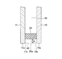
- FIG. 1 is a cross-sectional view showing an example of the multilayer glass according to the first embodiment of the present invention.
- the multilayer glass according to the present embodiment has two glass plates 10 and 11 and a spacer 20.
- the edge part of the multilayer glass is shown, and the glass plates 10 and 11 respectively have end faces 10a and 11a, and the end faces 10a and 11a constitute the outer peripheral surface of the multilayer glass.
- the spacer 20 is made of a thermoplastic resin.
- the two glass plates 10 and 11 are disposed to face each other via the spacer 20. That is, the height of the spacer 20 defines the distance between the two glass plates 10 and 11.
- the outer end face 20a of the spacer 20 is provided inward from the end faces 10a and 11a of the two glass plates 10 and 11 by a distance d.
- a hollow layer 30 is formed in the space inside the spacer 20 between the two glass plates 10 and 11. Further, outside the end face 20a of the spacer 20, a gap 40 is formed, which is surrounded in three directions by the outer edge portions 10b and 11b of the glass plates 10 and 11 and the end face 20a of the spacer 20.
- the distance d will be described as the distance between the end surfaces 10a and 11a of the glass plates 10 and 11 and the end surfaces of the end surfaces 20a outside the spacer 20.
- the distance d is the same as the distance between the end (or end) of the glass plates 10, 11 and the outer end (or end) of the spacer 20. Therefore, in the following embodiment, although it explains with the concept of three-dimensional distance, it shall be naturally included in the contents the plane contents on the principal surface of glass plates 10 and 11.
- the double glazing according to the present embodiment has the spacer 20 at a distance d from the end faces 10 a and 11 a of the two oppositely disposed glass plates 10 and 11.
- the spacer 20 By disposing the spacer 20 on the inner side by the distance d from the end faces 10a and 11a of the glass plates 10 and 11, it is possible to enhance the drainage and heat insulation of the multilayer glass.
- the end faces 10a and 11a of the glass plates 10 and 11 are covered with a frame, one of the main surfaces of one glass plate is indoors, and one of the main surfaces of the other glass plate is outdoor It is often used as a window fitted to the sash in an exposed form.
- the outer end face 20a of the spacer 20 is disposed so as to be on the inner side by a distance d than the end faces 10a and 11a of the glass plates 10 and 11 from the end face of the sash. Direct attack and heat transfer such as rainwater are prevented, and drainage and heat insulation are enhanced.
- the distance d is required to be 1 mm or more, preferably 3 mm or more, more preferably 5 mm or more, and still more preferably 6 mm or more.
- the distance d may be set to a predetermined distance in the range of 3 to 8 mm.
- the distance d may be set to a value exceeding 8 mm, when the spacer 20 is provided so much inside, the inner portion of the spacer 20 is exposed outside the frame when it is fitted to the sash, and the appearance is
- the distance d is preferably set to 8 mm or less, more preferably 7 mm or less because the appearance may be impaired.
- the distance d is set to a value such as 3 mm or 5 mm, the spacer 20 does not protrude from the frame when configured as a window fitted to a sash, which is advantageous for commercialization.
- the thickness in the direction parallel to the surface of the glass plates 10 and 11 of the spacer 20 can be made into various values by an application, it is good also as a value of the range of 3 mm or more and 15 mm or less, for example. It may be a value within the following range, or may be set to a value of about 7 mm.
- the width of the spacer 20 in the direction perpendicular to the surface of the glass plates 10 and 11 can be set to various values depending on the application, but may be, for example, a value in the range of 4 mm to 25 mm, 10 mm to 15 mm. It may be a value in the following range, for example, it may be set to a value of about 12 mm.
- a thermoplastic resin to be a material of the spacer 20 is applied to one of the main surfaces of the glass plates 10 and 11 and the other glass plates 10 and 11 It manufactures by making the main surface opposite to the glass plates 10 and 11 with which the spacer 20 was apply
- the spacer 20 is formed by applying a thermoplastic resin on the main surface of one of the glass plates 10 and 11 so as to draw it. Therefore, the spacer 20 can be formed in a state in which the distance d from the end faces 10a and 11a of the glass plates 10 and 11 is kept constant by performing the drawing accurately.
- the two glass plates 10 and 11 are disposed to face each other from the beginning, and the spacer 20 is injected and filled into the space between the two glass plates 10 and 11 from the outside of the glass plates 10 and 11 by extrusion. It differs greatly from the manufacturing method, and it is possible to secure the predetermined distance d accurately.
- the spacer 20 and the glass plates 10 and 11 may be directly bonded when the spacer 20 has a sufficient adhesive force, but the spacer 20 and the glass plate 10 may be bonded when the adhesive force of the spacer 20 is increased.
- An adhesive may be applied between the spacer 11 and the spacer 20 to securely bond the spacer 20 and the glass plates 10 and 11.
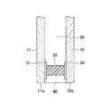
- FIG. 2 is a view showing an example of a double glazing according to an embodiment of the present invention provided with such an adhesive 50, 51.
- an adhesive 50 is provided between the spacer 20 and the glass plate 10
- an adhesive 51 is provided between the spacer 20 and the glass plate 11.
- the adhesives 50 and 51 may be provided between the spacer 20 and the glass plates 10 and 11 to securely bond the spacer 20 and the glass plates 10 and 11.
- the spacer 20 contacts the glass plate 10 or 11 in a region where the adhesive 50 or 51 is applied in order to ensure that the spacer 20 and the glass plate 10 or 11 adhere to each other.
- the region is wider than the region and includes the region where the spacer 20 and the glass plates 10 and 11 are in contact with each other.
- the spacers 20 can be adhered to the surfaces of the glass plates 10 and 11 uniformly and reliably.
- the thickness of the adhesives 50 and 51 may be set to various thicknesses depending on the application, but may be set to, for example, 0.1 ⁇ m to 50 ⁇ m.
- the adhesives 50 and 51 are not applied to the glass plates 50 and 51 immediately after bonding to the spacers 20, but the adhesives 50 and 51 are once applied and dried, and the adhesives 50 and 51 are adhesives.
- the spacer 20 is applied in a layered state. However, since the time for the adhesives 50 and 51 to dry is very short, it is possible to produce a multilayer glass as a continuous process. In addition, the detail of the manufacturing method of a multilayer glass is mentioned later.
- the spacer 20 is formed of a resin material, and preferably contains a hygroscopic agent in the resin material.
- a hygroscopic agent zeolite, silica gel or the like can be used, and zeolite is preferable because of high hygroscopic performance in a low humidity region.
- the shape of the zeolite there is no particular limitation on the shape of the zeolite, and a powdery one is preferable from the viewpoint of uniform dispersion in the resin material for the spacer. Further, the pore diameter is not particularly limited as long as it absorbs water vapor, and 4A zeolite powder which can be obtained inexpensively is desirable.
- the moisture absorption performance of the resin material for spacers is not easily defined because it is greatly influenced by environmental conditions such as temperature and humidity, but the temperature range of -20 ° C to + 60 ° C, which is at least the operating temperature range of double glazing It is desirable to have a hygroscopic performance of at least 0.1% with respect to the weight of the sealing material.
- a material made of a thermoplastic resin is used in view of the fact that the drying time (curing time) after the production of the multilayer glass can be shortened.
- a resin material containing a butyl rubber-based material so as to obtain a sufficiently low moisture permeability as the spacer 20 of the multilayer glass.
- a material that contributes to high hardness such as crystalline polyolefin, so as to obtain sufficient shape retentivity as the spacer 20 of multilayer glass.
- the thermoplastic resin material used as the material of the spacer 20 of the multilayer glass according to the present embodiment preferably contains a butyl-based rubber.
- the butyl-based rubber contained in the thermoplastic resin material includes two kinds of materials, a high molecular weight material constituting high molecular weight butyl rubber and a low molecular weight material constituting low molecular weight butyl rubber. Is preferred.
- the thermoplastic resin of the spacer 20 of the multi-layer glass according to the present embodiment includes two kinds of materials, a high molecular weight material constituting high molecular weight rubber and a low molecular weight material constituting low molecular weight butyl rubber The example comprised with resin is demonstrated.
- the high molecular weight butyl-based rubber and the low molecular weight butyl-based rubber have almost the same chemical structure but different molecular weights. Since the chemical structure is the same, the gas permeability, the chemical resistance and the like are the same, but the physical properties such as the melt viscosity and the elastic modulus are different because the molecular weight is different.
- the high molecular weight butyl-based rubber is a block-like solid and exhibits properties as an elastomer. On the other hand, low molecular weight butyl-based rubbers exhibit properties as viscous liquids and adhesives.
- the influence of the molecular weight of the high molecular weight butyl-based rubber is large. Therefore, in selecting the high molecular weight butyl-based rubber, a range showing the physical properties (high elastomer property and elasticity) of the high molecular weight butyl-based rubber It is preferable to use a lower molecular weight material.
- the high molecular weight butyl-based rubber a material having a number average molecular weight of 55,000 to 150,000 is preferably used, a material having a number average molecular weight of 60000 to 120,000 is more preferably used, and the number average molecular weight is It is more preferable to use a material of 65000 or more and 100000 or less, and it is particularly preferable to use a material with a number average molecular weight of 70000 or more and 80000 or less.
- a lower molecular weight butyl-based rubber is selected as the high molecular weight butyl-based rubber among high molecular weight butyl-based rubbers, a decrease in elastic modulus at room temperature occurs, and shape retention as a double-layered glass, for example, sheet slippage Etc may occur. Therefore, in order to lower the melt viscosity and maintain the elastic modulus at room temperature, in the selection of the low molecular weight butyl rubber, a higher molecular weight is within the range showing the physical properties (high viscosity) of the low molecular weight butyl rubber. It is preferred to select the material on the side.
- the low molecular weight butyl-based rubber a material having a number average molecular weight of 35,000 to 50,000 is preferably used, and a material having a number average molecular weight of 38,000 to 45,000 is more preferably used.
- butyl-based rubber material By selecting such a butyl-based rubber material, it is possible to maintain a room temperature elastic modulus while reducing the melt viscosity at high temperature, and to manufacture a replicated glass having high quality spacers 20 while enhancing productivity. It can be configured.
- a desiccant, an inorganic filler, and other additives are mix
- the desiccant for example, any of desiccants used by being mixed with spacers and sealants of conventional double glazing such as zeolite, alumina, silica gel and the like can be used.
- the inorganic filler calcium carbonate, talc, mica, carbon black and the like which are generally used as inorganic fillers can be used alone or in combination of two or more.
- the ratio of butyl rubber to the total amount of butyl rubber and crystalline polyolefin of the spacer 20 is preferably 50 to 98% by weight. If it is 50 weight% or more, the elastic modulus at room temperature can be increased. If it is 98 weight% or less, the melt viscosity at high temperature can be reduced.
- the proportion of the high molecular weight butyl-based rubber to the total amount of the spacers 20 is preferably 15 to 35% by weight, and more preferably 20 to 30% by weight. If it is 15 weight% or more, the elastic modulus at room temperature can be increased. If it is 35 weight% or less, the melt viscosity at high temperature can be reduced.
- the ratio of the crystalline polyolefin to the total amount of butyl rubber and crystalline polyolefin in the spacer 20 is preferably 2 to 50% by weight. It is preferably 5 to 40% by weight, more preferably 7 to 20% by weight, and still more preferably 8 to 15% by weight. If the proportion of the crystalline polyolefin is less than 2% by weight, the hardness of the butyl-based rubber is small, and if it exceeds 50% by weight, the properties of the crystalline polyolefin become main and the characteristics of the butyl-based rubber become difficult to express.
- the spacer 20 is formed by directly drawing and applying a resin material on the surface of one glass plate 10, 11 in the spacer shape, and pressing the other glass plate 10, 11 to provide between two or more glass plates 10, 11. Is preferable in terms of accurate placement formation of the spacers 20 and automation of the process of manufacturing the multilayer glass.
- the position of the spacer 20 is formed and the spacer 20 of the extruder An angle of about 5 to 90 ° occurs with the extrusion direction, and fluctuations between pressure and force when extruding the thermoplastic resin material cause the space between the spacer 20 and the end faces 10a and 11a of the glass plates 10 and 11 to change.
- the distance d is not constant.
- the distance d from the end faces 10a and 11a of the glass plates 10 and 11 can be kept constant.
- the distance d is kept constant with an accuracy of ⁇ 0.5 mm.
- the thickness of the adhesives 50 and 51 may be an appropriate thickness depending on the application, but the adhesives 50 and 51 may be used. Is thick, moisture may permeate from the adhesives 50 and 51. That is, if the thickness of the adhesive 50, 51 exceeds 50 ⁇ m, the moisture permeation in the adhesive 50, 51 can not be suppressed, and the dew point of the hollow layer 20 may not easily drop at the initial stage. Therefore, the thickness of the adhesives 50 and 51 is preferably 50 ⁇ m or less.
- the thickness of the adhesives 50, 51 is preferably 30 ⁇ m or less, more preferably 20 ⁇ m or less, still more preferably 10 ⁇ m or less, 3 ⁇ m or less Are particularly preferred, and 2 .mu.m or less is most preferred.
- the lower limit of the thickness of the adhesive layer 14 may be such that the adhesion between the glass plates 10 and 11 and the spacer 20 does not become insufficient as the performance of the double glazing because the adhesives 50 and 51 are smeared. It is preferable that it is 1 micrometer or more.
- the thickness of the adhesive 50, 51 is 0.1 ⁇ m or more, the adhesive function of bonding the spacer 20 and the glass plates 10, 11 can be performed without any problem.
- the thickness of the adhesives 50 and 51 may be 0.2 ⁇ m or more, and may be 0.3 ⁇ m or more.
- the spacer 20 itself has a certain degree of adhesiveness or adhesion to the glass plates 10 and 11, but there is a case where the adhesive strength is not such that there is no need to provide the adhesives 50 and 51, or sufficient adhesive strength is provided.
- the adhesives 50 and 51 may be provided on a part of the entire circumference of the double glazing in the sense of reinforcing the adhesiveness and adhesiveness of the spacer 20.
- the adhesives 50 and 51 are not particularly limited as long as they are conventionally proposed variously for glass / resin.
- a urethane-based adhesive, a polyester-based adhesive, an epoxy-based adhesive, an ⁇ -cyanoacrylate-based adhesive, an acrylic-based adhesive, etc. can be used that contains a compound having a hydrolyzable silyl group. .
- the glass plates 10 and 11 to be used are not limited to ordinary single-plate glass plates 10 and 11, but organic transparent resin plates called so-called resin glass, glass plates having a functional coating on the surface, and reinforcements subjected to reinforcement treatment Various things, such as glass, can be used. It is also possible to use laminated glass in which a plurality of these glass plates are joined via an adhesive interlayer, or laminated glass in which a resin film is laminated on the surface.
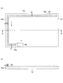
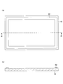
- FIG. 3 is the figure which showed an example of the middle step of the process of apply
- FIG. 3 (a) is a plan view in the middle of the process of applying a spacer
- FIG. 3 (b) is a cross-sectional view taken along the line AA of FIG. 3 (a).
- the spacer 20 is positioned on the main surface of the glass plate 10 at a position which is inward from the end face 10a of the glass plate 10 by a distance d.
- Drawing is formed.
- the spacer 20 is extruded and applied onto the main surface of the glass plate 10 as when extruding a tooth powder from the tube-like drawing unit 60, and the spacer 20 is drawn and formed.
- the drawing unit 60 moves along the direction in which the spacer 20 is drawn and formed. That is, the drawing unit 60 moves so as to draw a rectangular frame shape on the main surface of the glass plate 10, and forms the spacer 20 having a frame-like planar shape.
- the rectangular glass plate 10 has four sides, and four sides of the end face 10a.
- the spacer 20 is drawn, for example, so that the outer end surface 20a of the spacer 20 is located at a distance d from any of the end surfaces 10a.
- the distance d when the distance d from the end face 10a is desired to be different between the vertical direction and the horizontal direction, the distance d can be set as such.
- the distance d can be set for each side, and it is also possible to set different distances d1 to d4 for each of the four sides.
- the distance d between the end faces 10a and 11a of the glass plates 10 and 11 and the end face 20a outside the spacer 20 in each side is constant, but the set value of the distance d is different for each side,
- the distances d1 to d4 are set.
- the distances d1 and d2 are set for each of the vertical and horizontal directions.
- the distance d may be 1 mm or more, preferably 3 mm or more, more preferably 3 mm or more and 8 mm or less.
- the spacer 20 Since the spacer 20 is at a high temperature when discharged from the drawing unit 60, it has a certain degree of flexibility, but at the stage where it is applied on the main surfaces of the glass plates 10 and 11, it is already harder than tooth powder (viscosity) Is not less than 0.6 kPa ⁇ s and not more than 7.0 kPa ⁇ s), and after being applied on the main surface of the glass plate 10, it is cooled at normal temperature, so the curing proceeds further.
- viscosity viscosity
- the drawing unit 60 does not have to be a flexible material such as a tube-like container containing tooth powder, and may be configured using a general metal member or the like as long as the spacer 20 can be drawn and applied. .
- the glass plate 10 may be placed horizontally to form the spacer 20 regardless of the arrangement state of the glass plate 10 in particular. May be performed in a state of being stood on a vertical surface such as a wall surface, or may be performed while supporting the lower part of the glass plate 10 and maintaining the main surface of the glass plate 10 vertically.
- the spacers 20 have a certain degree of hardness at the stage of being applied to the glass plate 10, it is not necessary to necessarily carry out the step of applying the spacers while keeping the glass plate 10 horizontal. It can be implemented by any method depending on the configuration of the apparatus for drawing and forming.
- the spacer 20 has a shape having a convex protrusion on the main surface of the glass plate 10 immediately after being applied. That is, the upper surface is not a flat cylindrical shape, and the upper surface of the cylinder has a raised shape.
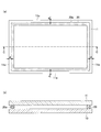
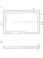
- FIG. 4 is a view showing an example of the completion stage of the step of applying the spacer in the method of manufacturing the multilayer glass shown in FIG.
- FIG. 4 (a) is a plan view of the completion stage of the step of applying a spacer
- FIG. 4 (b) is a cross-sectional view taken along the line BB in FIG. 4 (a).
- a rectangular frame-shaped spacer 20 is formed on the main surface of the glass plate 10.
- the outer end face 20a of the spacer 20 is formed at a position which is inward by a distance d from the end face 10a of the glass plate 10 on four sides.
- the distance d may be made different for each side, but in the present embodiment, an example in which the same distance d is set for all four sides will be described.
- the spacers 20 having a convex shape on the main surface of the glass plate 10 are formed.
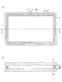
- FIG. 5 is the figure which showed an example of the process of bonding together the glass plate of the manufacturing method of the multilayer glass shown in FIG.
- FIG. 5 (a) is a plan view of the process of bonding the glass plates
- FIG. 5 (b) is a cross-sectional view taken along the line CC in FIG. 5 (a).
- another glass plate 11 is disposed opposite to the glass plate 10 and pressed against the surface of the glass plate 10 on which the spacers 20 are formed.
- the glass plates 10 and 11 are bonded to each other.
- the convex portion on the spacer 20 is pressed and crushed by the glass plate 11, and the outer end face 20a of the spacer 20 is in a direction parallel to the major surfaces of the glass plates 10 and 11. Protruding into a convex surface. Thereby, the void in the spacer 20 can be expelled, and the high quality spacer 20 can be formed.
- the spacer 20 is convex in the direction parallel to the main surfaces of the glass plates 10, 11, it can be confirmed that the bonding of the glass plates 10, 11 is reliably performed, and the reliability Can be enhanced.
- the spacer 20 is enlarged in the main surface direction from the side of the glass plate 11 bonded as compared with the spacer 20 of FIG. 4A, and 4 of the glass plate 11 It can be confirmed that the outer end face 20a of the spacer 20 is positioned at the inside of a distance d from the two end faces 11a.
- the spacers 20 are positioned at an inside position of the distance d from the end faces 10 a and 11 a of the two glass plates 10 and 11 opposite to each other.
- the end face 20a of the outer side of can be arranged, and a double glazing having high drainage and heat insulation can be manufactured.
- FIG. 6 is a view showing an example of a step of applying a first adhesive in the method of manufacturing the multilayer glass shown in FIG.
- FIG. 6 (a) is a plan view of the step of applying the first adhesive
- FIG. 6 (b) is a cross-sectional view taken along the line DD in FIG. 6 (a).
- the adhesive 50 is applied on the main surface of the first glass plate 10 of the two glass plates 10 and 11. Ru.
- the adhesive 50 is preferably applied to the area including the area where the spacer 20 is to be formed. Therefore, as shown in FIG. 6A, the adhesive 50 is applied in a frame shape having a rectangular frame shape like the spacer 20 and having a width wider than that of the spacer 20. preferable.
- the application of the adhesive 50 may be performed by various methods as long as an appropriate amount of the adhesive 50 can be applied to a predetermined portion of the main surface of the glass plate 10.
- the adhesive 50 may be a glass plate using a nozzle. You may make it apply
- the adhesive 50 is applied in a frame shape on the main surface of the glass plate 10.
- the adhesive 50 preferably has a thickness of 50 ⁇ m or less.
- the adhesive 50 can be dried in a short time of 30 seconds to 20 minutes.
- FIG. 7 is a view showing an example of a step of applying a second adhesive in the method of manufacturing the multilayer glass shown in FIG.
- FIG. 7 (a) is a plan view of a step of applying a second adhesive
- FIG. 7 (b) is a cross-sectional view taken along the line EE of FIG. 7 (a).
- the adhesive 51 is applied on the main surface of the second glass plate 11 of the two glass plates 10 and 11. Ru.
- the adhesive 51 is preferably the same as the adhesive 50 used for the glass plate 10.
- the application position and application method of the adhesive 51 are the same as those described with reference to FIG.
- FIG. 8 is a view showing an example of a process of applying a spacer in the method of manufacturing the multilayer glass shown in FIG.
- FIG. 8 (a) is a plan view of a process of applying a spacer
- FIG. 8 (b) is a cross-sectional view taken along line FF of FIG. 8 (a).
- the end surface is on the adhesive 50 applied to the glass plate 10 and at an inner position at a distance d from the end surface 10a of the glass plate 10.
- the spacer 20 is formed so that 20a may be located.
- the spacer 20 may be formed by the same method as described with reference to FIGS. 3 and 4. In FIG. 8, the spacer 20 is not formed directly on the main surface of the glass plate 10, but the difference is that the spacer 20 is formed on the main surface of the glass plate 10 to which the adhesive 50 is applied.
- the spacer 20 may be formed toward the second glass plate 11, it is preferable to form the spacer 20 after the adhesive 50 is dried, so in the present embodiment, adhesion is performed first.
- the spacer 20 is formed on the main surface of the first glass plate 10 to which the agent 50 is applied.
- the spacer 20 may be formed on the main surface of the second glass plate 11.
- a spacer 20 having a convex shape is formed on the adhesive 50.
- FIG. 9 is the figure which showed an example of the process of bonding together the glass plate of the manufacturing method of the multilayer glass shown in FIG.
- FIG. 9 (a) is a plan view of the process of bonding the glass plates
- FIG. 9 (b) is a sectional view taken along the line GG in FIG. 9 (a).
- the spacer 20 is formed so as to be included in the adhesive 51.
- the spacer 20 itself is formed to have an end face 20a located inside by a distance d from the end face 11a, as described in FIG.
- a spacer 20 is provided between two glass plates 10, 11 disposed opposite to each other with the adhesive 50, 51.
- the contents are the same as those described with reference to FIG. 5 except that the adhesives 50 and 51 are provided between the glass plates 10 and 11 and the spacer 20, respectively, and thus the description thereof is omitted.
- the spacer 20 is hollowed by a distance d from the end faces 10a, 11a of the glass plates 10, 11 while making the adhesion between the spacer 20 and the glass plates 10, 11 more reliable. It can be provided on the layer side to improve drainage and heat insulation.
- each side has a distance d of 1 mm or more from the end faces 10a and 11a of the glass plates 10 and 11, and the distance is set within a range of 3 mm to 8 mm. preferable.
- FIG. 10 is a view showing an example of the multilayer glass according to the second embodiment of the present invention.
- FIG. 10A is a view showing an example in which the glazing channel 120 is attached to the multilayer glass according to the first embodiment, mounted on the setting block 130, and attached to the sash 110, 111. As shown in FIG.
- sash 110, 111 are frames for double glazing, and they are installed on the surface of ceiling 100 and floor 101 respectively.
- the spacer 20 is a resin, it is not necessarily resistant to heat, and the shape of the spacer 20 may be deformed.
- FIG. 10B is a view showing an example in which the shape of the spacer 20 is deformed. As shown in FIG. 10B, when the shape of the spacer 20 is deformed and broken, a phenomenon occurs in which the glass plates 10 and 11 are slipped off. Such a state is not preferable, and fire prevention measures can not be said to be sufficient. Therefore, in the second embodiment, an example of a double glazing with fire prevention measures will be described.
- FIG. 11 is a view showing an example of the upper end portion of the multilayer glass according to the second embodiment.
- the upper end of the multi-layer glass supported by the sash 110 via the glazing channel 120 is shown.
- the double glazing is provided by supporting the outer side surfaces of the glass plates 10 and 11 so as to be sandwiched by the glazing channels 120.
- the outer end face 20a of the spacer 20 is recessed in a central form with respect to the end faces 10a and 11a of the glass plates 10 and 11, and the inner side faces of the glass plates 10 and 11
- a recess (air gap) 40 is formed by the outer edge portions 10 b and 11 b and the outer end surface 20 a of the spacer 20.
- the member 80 is provided so that this recessed part 40 may be filled.
- the member 80 is made of a material having a thermal decomposition temperature or melting point higher than the thermal decomposition temperature of the spacer 20. That is, even if the spacer 20 is thermally decomposed by heating, a material which can be held as it is without softening is selected as the member 80. If the thermal decomposition temperature or melting point of the member 80 is higher than the thermal decomposition temperature of the spacer 20, various materials can be applied depending on the application, but preferably, the heating assumed It is preferable that the thermal decomposition temperature or the melting point of the member 80 be higher than the temperature, and it is made of a material that can sufficiently withstand heating.
- the thermal decomposition temperature or melting point of the member 80 is, for example, 450 ° C. or higher, preferably 500 ° C. or higher, more preferably 550 ° C. or higher, particularly preferably 600 ° C. or higher, and 650 ° C. or higher Most preferably.
- the upper limit of the thermal decomposition temperature or the melting point is not particularly limited, but may be 2000 ° C. or less, 1500 ° C. or less, or 1000 ° C. or less.
- the thermal decomposition temperature or melting point of the member 80 is preferably 100 ° C. or more higher than the thermal decomposition temperature of the spacer 20, more preferably 150 ° C. or higher, further preferably 200 ° C. or higher, and 250 ° C.
- the temperature be 300 ° C. or higher.
- the thermal decomposition temperature is measured by a differential thermal / thermogravimetric measurement apparatus (for example, TGA Q50 manufactured by TA Instruments), and the member 80 or spacer at room temperature (25 ° C.) to 10 ° C./minute in an air atmosphere. This is the temperature at which the mass of the member 80 or the spacer 20 becomes 60% with respect to the mass at room temperature (25 ° C.) when the temperature 20 is raised.
- the member 80 does not have to be provided on the entire periphery of the multilayer glass, and may be provided on a part.
- the phenomenon that the multilayer glass is slipped off due to the deformation of the spacer 20 described above is most likely to occur near the upper end portion of the multilayer glass and is less likely to occur at the lower end portion.
- the member 80 may be provided only at the upper end portion of the multilayer glass, or may be provided only at the upper end portion and the side portion of the multilayer glass.
- the member 80 may be provided on the entire periphery of the multilayer glass, the heat insulating property is improved by providing the void portion 40, and in particular, the void portion 40 is provided at the lower end portion of the multilayer glass. Since the drainage property is also improved in the case where it is present, the member 80 may be provided within a range that does not impair the heat insulation property and the drainage property.
- the member 80 may be provided only at the upper end of the multilayer glass, or the member 80 may be provided only at the side of the multilayer glass, or the multilayer may be provided.
- the member 80 may be provided on the upper end portion and the side portion of the glass.
- the member 80 may be configured as a through member provided completely along one side of the multilayer glass, or may be provided in multiple layers such that it is provided on a part of the upper end and a part of the side part.
- the configuration may be such that the member 80 is provided only in a part of the recess (void) 40 of the glass. This is because the occurrence of the phenomenon that the glass plates 10 and 11 collapse inward can be prevented if the member 80 is provided even in part.
- the relationship with the depth of the cavity 40 of the member 80 can be variously determined depending on the application. That is, the member 80 may have a height smaller than the depth of the void 40, or may have the same height as the depth of the void 40, or may have a height larger than the depth of the void 40. You may have.
- FIG. 12 is a view showing an example in which the metal spacer 81 is provided in the recess (gap) 40.
- Metals such as aluminum and stainless steel function as an expanding material that expands when heated.
- aluminum is inexpensive and has a high thermal expansion coefficient, so it can be suitably used as an expansion material.
- metals including aluminum and stainless steel have a very high melting point, they have sufficient heat resistance and thermal expansion properties as members used for fire protection. Therefore, the metal spacer 81 such as aluminum may be provided in the recess 40.
- the expansive material in the recess 40 By providing the expansive material in the recess 40, the distance between the glass plates 10 and 11 can be maintained, and a pressing force directed outward can be applied to the metal angle 90, so the phenomenon in which the glass plates 10 and 11 slip off Can be prevented.
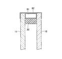
- FIG. 13 is a view showing an example in which the upper end portions of the glass plates 10 and 11 are covered with an aluminum tape 82 in addition to the metal spacer 81.
- the effects of the metal spacer 81 and the metal piece described above can be obtained not only in the recess 40 but also in the case of covering the glass plates 10 and 11 from the outside. Therefore, the upper end portions of the glass plates 10 and 11 may be covered with the aluminum tape 82 as necessary.
- a metal tape of another type or a metal plate including an aluminum plate can be used instead of the aluminum tape 82.
- FIG. 14 is a view showing an example in which a thermally expandable refractory material 83 such as Fiblock (registered trademark, manufactured by Sekisui Chemical Co., Ltd.) is provided in the recess 40.
- the fi-block is a tape-like or sheet-like thermally expandable refractory material 83, which is made of a material having both polyurethane characteristics and noncombustibility, and as shown in FIG.
- the glass plates 10 and 11 can be supported even if the spacer 20 is softened, because they can be provided by being attached to the side surfaces and thermally expand in the event of a fire and exhibit sufficient fire resistance.
- the fibrock is given as an example, and various thermally expandable refractory materials 83 having similar properties can be used.
- FIG. 15 is a view showing an example in which a plurality of thermally expandable refractory materials 83 such as fibrock are provided in the recess 40 so as to be stacked in the thickness direction of the multilayer glass.
- a tape-like or sheet-like thermally expandable refractory material 83 such as fibrock
- the amount of thermal expansion in the thickness direction of the tape or sheet is larger than the amount of thermal expansion in the longitudinal direction.
- the thermal expansion amount can be increased more than in the case of one sheet. Therefore, as shown in FIG. 15, a tape-like or sheet-like thermally expandable refractory material 83 may be provided so as to overlap in the thickness direction of the multilayer glass.
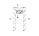
- FIG. 16 is a view showing an example in which the thermal expansion sealing material 84 is provided in the recess 40.
- the thermal expansion seal material 84 is a case where the seal material is directly filled in the recess 40, and such thermally expandable seal material is also developed by various companies. Therefore, such a thermal expansion sealing material 84 can be filled in the recess 40 and used as an expansion material.
- the member 80 may have a thermal decomposition temperature or a melting point higher than the thermal decomposition temperature of the spacer 20, and is not necessarily an expanding material that expands by heating. However, when using an expanding material for the member 80, the thermal expansion of the member 80 The rate is, for example, preferably 5 times or more, more preferably 10 times or more, further preferably 20 times or more, and particularly preferably 25 times or more.
- the upper limit of the thermal expansion coefficient is not particularly limited, but may be 50 times or less.
- the coefficient of thermal expansion is the ratio of the volume of the member 80 when the member 80 is heated at 600 ° C. for 20 minutes to the volume of the member 80 at room temperature (25 ° C.).
- members 80 to 84 whose thermal decomposition temperature or melting point is higher than the thermal decomposition temperature of the spacer 20 are placed in the recess (gap) 40 outside the spacer 20.
- the fire protection performance can be improved.
- by partially providing the members 80 to 84 it is possible to improve the fire protection performance while maintaining the excellent heat insulating property and drainage property of the multilayer glass, and the multilayer glass excellent in functionality and safety. Can be configured.
- FIG. 17 is a view showing an example of the multilayer glass according to the third embodiment of the present invention.
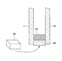
- the multilayer glass according to the third embodiment has a protective member 90 in the recess (void) 40.
- the protective member 90 is a member for protecting the end of the multilayer glass, and has a shape which is thicker than the depth of the recess 40 and protrudes beyond the end faces of the glass plates 10 and 11. That is, since it protrudes from the end surface of the glass plates 10 and 11, it collides with an obstacle earlier than the end surfaces of the glass plates 10 and 11, and the end surfaces of the glass plates 10 and 11 can be protected.
- the protective member 90 various materials such as resins such as PVC (polyvinyl chloride) and PVB (polyvinyl butyral), paper, corrugated poles, and foamed polystyrene can be used.
- resins such as PVC (polyvinyl chloride) and PVB (polyvinyl butyral)
- paper corrugated poles
- the protective member 90 may be provided at the time of conveyance of the multilayer glass, at the time of operation, etc., may be removed at the time of installation, and may be attached as it is when it can be installed as it is attached.
- the protective member 90 does not have to be provided all around, and may be provided only in necessary portions. That is, the protective member 90 is configured in a rectangular piece shape shorter than the length of one side of the glass plates 10, 11, and the end faces of the glass plates 10, 11 of the multilayer glass can avoid contact with other external members.
- the number of protection members 90 may be provided. Even in such an installation, the purpose of protecting the end faces of the glass plates 10 and 11 can be sufficiently achieved.
- the protective member 90 can be of various sizes and arrangements depending on the application.
- FIG. 18 is a view showing an example in which the protective member 91 is provided at the corner of the multilayer glass.
- a protective member 91 having an L shape may be provided to cover the corner of the multilayer glass.
- the protective member 91 also has a thickness greater than the depth of the recess 40 and has a shape that protrudes from the end faces of the glass plates 10 and 11.
- the protection member 90 of FIG. 17 and the protection member 91 of FIG. 18 can be used in combination.
- the protective member 91 may be provided at the corner of the multilayer glass, and the protective member 90 may be provided at the side portion.
- FIG. 19 is a view showing an example of a protective member 92 having a shape that completely covers the end face of the corner of the multilayer glass.
- the protective member 92 has an L shape to fit the corner, and a protrusion 92 a engaged with the recess 40 and a base 92 b covering the end faces of the glass plates 10 and 11. It is configured to have.
- the portions of the protective member 92 that project from the glass plates 10 and 11 may be configured to be wide, and the end surfaces of the glass plates 10 and 11 may be covered. The end faces of the glass plates 10 and 11 can be protected more reliably.
- the protective members 90 to 92 may be attached to the glass plates 10, 11, for example, with a simple and easily peelable adhesive. It is used by transporting the protective members 90 to 92 in a state of being attached to the multilayer glass, and removing the protective members 90 to 92 from the glass plates 10 and 11 when installing the multilayer glass on site. May be
- the protective members 90 to 92 thicker than the depth of the recess (void) 40 are provided in the recess 40 so that the end faces of the glass plates 10 and 11 can be obtained. Also, the outer end face of the protection members 90 to 92 can be protruded. Thus, the end faces of the glass plates 10 and 11 can be prevented from coming into contact with other members, and the end faces of the glass plates 10 and 11 can be reliably protected, thereby preventing damage to the multilayer glass during transportation or the like. Can.
- the thickness of the glass plates 10 and 11 is set to 3 mm and the width of the hollow layer 30, ie, the distance between the glass plates 10 and 11 is set to 12 mm.
- the spacer 20 is made of butyl rubber, and the thickness of the spacer 20 in the direction parallel to the main surfaces of the glass plates 10 and 11 is 7 mm, and the spacer 20 in the direction perpendicular to the main surfaces of the glass plates 10 and 11
- the height was set to 12 mm. This is of course the same dimension as the width of the hollow layer 30.
- Distance d from end faces 10a and 11a of glass plates 10 and 11 of end face 20a outside spacer 20 in gap 40 was set to 1 mm, 3 mm, 5 mm, and 7 mm.
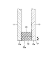
- FIG. 20 is a cross-sectional view showing the configuration of the multilayer glass according to the comparative example.
- the glass plates 10 and 11 and the spacer 20 have the same material and configuration as the multilayer glass according to the example.
- the distance d between the outer end face 20a of the spacer 20 and the end faces 10a and 11a of the glass plates 10 and 11 was set to 5 mm, and the secondary seal 70 was filled without using the void 40 as a void. As a result, substantially, the distance d between the outer end face 20a of the spacer 20 and the end faces 10a and 11a of the glass plates 10 and 11 is zero.
- the double glazing according to the comparative example is a double glazing in which the end face 20a outside the spacer 20 and the end faces 10a and 11a of the glass plates 10 and 11 form the same plane, similarly to the conventionally used double glazing It is.
- the double glazing according to the present example and the double glazing according to the comparative example are placed under the conditions of 0 ° C. on the outdoor side and 20 ° C. on the indoor side, and the thermal conductivity (W / mK) of the glass plates 10 and 11 is 1
- the thermal conductivity (.00) was calculated when the thermal conductivity (W / mK) of butyl rubber was set to 0.24, and the thermal conductivity (W / mK) of the secondary seal 70 to 0.40.
- the temperature at the innermost point P of the end surface 10a on the indoor side is calculated as the indoor side edge surface temperature.
- the temperature at the same point P was also calculated in the embodiment shown in FIG.
- Example 1 The case where the distance d of the outer end face 20a of the spacer 20 from the end faces 10a and 11a of the glass plates 10 and 11 is 1 mm is Example 1, the case where the distance d is 3 mm is the example 2, and the distance d is 5 mm. In the third embodiment, the case where the distance d is 7 mm is the fourth embodiment.
- Table 1 shows the measurement results of the edge temperature of the comparative example.
- the edge temperature on the indoor side was in the range of 9.6 to 9.9 ° C. in Examples 1 to 4.
- the influence of the 0 ° C. temperature outside the room decreases, and the temperature increases. That is, it can be seen that the heat insulation is improved.
- the edge portion temperature on the indoor side in the comparative example is 9.1 ° C., which is lower by 0.5 ° C. or more than in the first to fourth embodiments, and is affected by the outdoor temperature. It can be seen that the heat insulation is reduced.
- FIG. 21 is a view showing the relationship between the distance d of the air gap 40 and the indoor side edge temperature in the examples 1 to 4 and the comparative example.
Landscapes
- Chemical & Material Sciences (AREA)
- Engineering & Computer Science (AREA)
- Chemical Kinetics & Catalysis (AREA)
- Structural Engineering (AREA)
- Ceramic Engineering (AREA)
- Life Sciences & Earth Sciences (AREA)
- Civil Engineering (AREA)
- General Chemical & Material Sciences (AREA)
- Geochemistry & Mineralogy (AREA)
- Materials Engineering (AREA)
- Organic Chemistry (AREA)
- Securing Of Glass Panes Or The Like (AREA)
- Joining Of Glass To Other Materials (AREA)
Abstract
2枚以上のガラス板が、その間に中空層を形成するようにスペーサを介して対向配置された複層ガラスであって、 前記スペーサは熱可塑性樹脂からなり、 前記スペーサの端が前記ガラス板の端から1mm以上の所定距離分、前記中空層側に設けられている。
Description
本発明は、複層ガラス及びその製造方法に関する。
従来から、2枚以上のガラス板が、その間に中空層を形成するようにスペーサを介して隔置されて対向配置された複層ガラスにおいて、スペーサが、25℃におけるJIS A硬度が10~90の熱可塑性樹脂組成物からなる複層ガラスが知られている(例えば、特許文献1参照)。
かかる特許文献1に記載の複層ガラスにおいては、二次シール材を用いずに、スペーサのみで寿命、形状維持性、成形性を満足させ、製造工程を大幅に簡素化して生産性を向上させている。
しかしながら、特許文献1に記載の複層ガラスにおいては、2枚のガラス板を対向配置させた状態で、外側から押出成形等により対向配置された2枚のガラス板の間に注入するようにしてスペーサを成形することが開示されている。しかし、この方法ではスペーサの成形位置の制御を行うことはできず、ガラス板の端部から一定の距離を有する位置に、ガラス板の外形に沿うように正確にスペーサを配置して複層ガラスを製造することはできなかった。一方、ガラス板の外形(端部)からはみ出したスペーサの処理を行う等の処置を行えば、対向配置された2枚のガラス板の端部にスペーサの端部が揃うように複層ガラスを構成することは可能であるが、熱可撓性樹脂からなるスペーサを複層ガラスの端部に揃えて配置すると、外部からの水分を容易に吸収して排水性が悪くなるという問題を生じた。また、スペーサをガラス板の端部に揃えて配置すると、室外と室内との間の熱伝達効果が高くなってしまい、複層ガラスの断熱性を低下させてしまうという問題も生じた。
そこで、本発明は、断熱性及び排水性が高い複層ガラス及びその製造方法を提供することを目的とする。
上記目的を達成するため、本発明の一態様に係る複層ガラスは、2枚以上のガラス板が、その間に中空層を形成するようにスペーサを介して対向配置された複層ガラスであって、
前記スペーサは熱可塑性樹脂からなり、
前記スペーサの端が前記ガラス板の端から1mm以上の所定距離分、前記中空層側に設けられている。
前記スペーサは熱可塑性樹脂からなり、
前記スペーサの端が前記ガラス板の端から1mm以上の所定距離分、前記中空層側に設けられている。
本発明によれば、複層ガラスの断熱性と排水性を向上させることができる。
以下、図面を参照して、本発明を実施するための形態の説明を行う。
[第1の実施形態]
図1は、本発明の第1の実施形態に係る複層ガラスの一例を示した断面図である。図1に示されるように、本実施形態に係る複層ガラスは、2枚のガラス板10、11と、スペーサ20とを有する。図1においては、複層ガラスの端部が示されており、ガラス板10、11は、各々端面10a、11aを有し、端面10a、11aが複層ガラスの外周面を構成する。詳細は後述するが、スペーサ20は熱可塑性樹脂から構成される。
図1は、本発明の第1の実施形態に係る複層ガラスの一例を示した断面図である。図1に示されるように、本実施形態に係る複層ガラスは、2枚のガラス板10、11と、スペーサ20とを有する。図1においては、複層ガラスの端部が示されており、ガラス板10、11は、各々端面10a、11aを有し、端面10a、11aが複層ガラスの外周面を構成する。詳細は後述するが、スペーサ20は熱可塑性樹脂から構成される。
2枚のガラス板10、11は、互いにスペーサ20を介して対向配置されている。即ち、スペーサ20の高さが2枚のガラス板10、11同士の間隔を定めている。スペーサ20の外側の端面20aは、2枚のガラス板10、11の端面10a、11aから距離dだけ内側に設けられている。そして、2枚のガラス板10、11の間のスペーサ20の内側の空間には、中空層30が形成されている。また、スペーサ20の端面20aの外側には、ガラス板10、11の外縁部10b、11bとスペーサ20の端面20aとで三方が囲まれた空隙部40が形成されている。
なお、以下の説明において、距離dをガラス板10、11の端面10a、11aとスペーサ20の外側の端面20aの端面同士の距離として説明するが、ガラス板10、11の主面上で見れば、距離dはガラス板10、11の端(又は端部)からスペーサ20の外側の端(又は端部)の距離と同一である。よって、以下の実施形態では、立体的な距離の概念で説明するが、その内容には、ガラス板10、11の主面上の平面的な内容も当然に含まれているものとする。
上述のように、本実施形態に係る複層ガラスは、対向配置された2枚のガラス板10、11の端面10a、11aから距離dだけ内側に入った位置にスペーサ20を有する。スペーサ20をガラス板10、11の端面10a、11aよりも距離d分、内側に配置することにより、複層ガラスの排水性及び断熱性を高めることができる。本実施形態に係る複層ガラスは、ガラス板10、11の端面10a、11aがフレームで覆われ、一方のガラス板の主面の一方が室内、他方のガラス板の主面の一方が室外に露出する形でサッシに嵌合した窓として使用される場合が多い。そのような用い方をする場合、熱可塑性樹脂からなるスペーサ20の端面20aがガラス板10、11の端面10a、11aに揃う構成の場合、雨水等の水分がスペーサに容易に吸収されてしまい、排水性が低下してしまうという問題がある。また、スペーサ20の端面20aがガラス板10、11の端面10a、11aに揃って同一面を形成する構成であると、スペーサ20がヒートブリッジとして機能してしまい、室外の冷気又は熱気を室内に容易に伝達してしまうおそれがある。そうすると、複層ガラスの断熱性が低下してしまうという問題がある。
そこで、本実施形態に係る複層ガラスにおいては、スペーサ20の外側の端面20aがガラス板10、11の端面10a、11aよりも距離d分、内側に来るように配置し、サッシの端面からの雨水等の直接的なアタックや熱伝達を防止し、排水性及び断熱性を高める構成にしている。
距離dは、1mm以上は必要であり、好ましくは3mm以上、より好ましくは5mm以上、さらに好ましくは6mm以上確保する。例えば、距離dを3~8mmの範囲の所定距離に設定してもよい。距離dを、8mmを超える値に設定してもよいが、あまり内側にスペーサ20を設けると、サッシに嵌合した場合にスペーサ20の内側の部分がフレームからはみ出して露出してしまい、外観の美観が損なわれるおそれがあるので、距離dは好ましくは8mm以下、より好ましくは7mm以下に設定する。例えば、距離dを3mm、5mmといった値に設定すれば、サッシに嵌合した窓として構成した場合に、スペーサ20がフレームからはみ出さないので、製品化には有利である。
なお、スペーサ20のガラス板10、11の面と平行な方向における厚さは、用途により種々の値とすることができるが、例えば、3mm以上15mm以下の範囲の値としてもよく、5mm以上10mm以下の範囲の値としてもよく、7mm程度の値に設定してもよい。
また、スペーサ20のガラス板10、11の面と垂直な方向における幅も、用途により種々の値に設定することができるが、例えば、4mm以上25mm以下の範囲の値としてもよく、10mm以上15mm以下の範囲の値としてもよく、例えば、12mm程度の値に設定してもよい。
詳細は後述するが、本実施形態に係る複層ガラスは、ガラス板10、11のいずれか一方の主面にスペーサ20の材料となる熱可塑性樹脂を塗布し、他方のガラス板10、11の主面をスペーサ20が塗布されたガラス板10、11に対向させ、他方のガラス板10、11の主面をスペーサ20に押し付けるようにして貼り合わせることにより製造される。ここで、スペーサ20は、いずれか一方のガラス板10、11の主面上に熱可塑性樹脂を描画するように塗布することにより形成される。よって、描画を正確に行うことにより、ガラス板10、11の端面10a、11aからの距離dを一定に保った状態でスペーサ20を形成することができる。この点、2枚のガラス板10、11を最初から対向配置し、2枚のガラス板10、11の間の空間にガラス板10、11の外側から押出成形によりスペーサ20を注入して充填する製造方法とは大きく異なっており、所定距離dを正確に確保することが可能である。
なお、スペーサ20に十分な接着力がある場合には、スペーサ20とガラス板10、11とは直接接合してよいが、スペーサ20の接着力を高める場合には、スペーサ20とガラス板10、11との間に接着剤を塗布し、スペーサ20とガラス板10、11を確実に接着してもよい。
図2は、そのような接着剤50、51を設けた本発明の実施形態に係る複層ガラスの一例を示した図である。図2に示されるように、スペーサ20とガラス板10との間に接着剤50が設けられ、スペーサ20とガラス板11との間に接着剤51が設けられている。このように、スペーサ20とガラス板10、11との間に接着剤50、51を設け、スペーサ20とガラス板10、11とを確実に接着する構成としてもよい。なお、接着剤50、51を設ける場合、スペーサ20とガラス板10、11同士を確実に接着させるべく、接着剤50、51が塗布される領域は、スペーサ20がガラス板10、11に接触する領域よりも広く、スペーサ20とガラス板10、11とが接触する領域を包含する領域とすることが好ましい。これにより、均一かつ確実にスペーサ20をガラス板10、11の表面に接着させることができる。ここで、接着剤50、51の厚さは、用途に応じて種々の厚さとされてよいが、例えば、0.1μm以上50μm以下に設定されてもよい。なお、接着剤50、51は、ガラス板50、51に塗布してすぐにスペーサ20を接着させるのではなく、一旦接着剤50、51を塗布して乾燥させ、接着剤50、51が接着剤層となった状態でスペーサ20を塗布する。但し、接着剤50、51が乾燥する時間は非常に短いので、連続した工程として複層ガラスを製造することが可能である。なお、複層ガラスの製造方法の詳細については後述する。
次に、スペーサ20に用いられる材料の例について、より詳細に説明する。
スペーサ20は、樹脂材料から形成されたものであり、吸湿剤を樹脂材料に含有することが好ましい。この吸湿剤としては、ゼオライトやシリカゲル等が使用でき、低湿度領域での吸湿性能が高いことからゼオライトが好ましい。
ゼオライトの形状には特に制限はなく、スペーサ用の樹脂材料における均一分散性の観点から、パウダー状のものが好ましい。また、孔径は水蒸気を吸湿するものであれば特に制限はなく、安価に入手可能な4Aゼオライトパウダーが望ましい。
スペーサ用樹脂材料が有する吸湿性能は、温度、湿度等の環境条件により大きく左右されるため、規定が容易ではないが、少なくとも複層ガラスの使用温度領域である-20℃~+60℃の温度範囲で、シール材料の重量に対し0.1%以上の吸湿性能を有することが望ましい。
スペーサ20を形成する樹脂材料としては、複層ガラスの製造後の乾燥時間(養生時間)が短縮できる点に鑑みて、熱可塑性樹脂からなる材料を用いる。また、複層ガラスのスペーサ20として充分な低透湿性が得られるように、ブチルゴム系材料を含む樹脂材料を用いることが好ましい。さらに、複層ガラスのスペーサ20として充分な形状保持性が得られるように、結晶性ポリオレフィン等の高硬度化に寄与する材料を加えることが好ましい。
このように、本実施形態に係る複層ガラスのスペーサ20の材料として用いられる熱可塑性樹脂材料は、ブチル系ゴムを含むことが好ましい。そして、熱可塑性樹脂材料に含有されるブチル系ゴムは、高分子量ブチル系ゴムを構成する高分子量側の材料と、低分子量ブチル系ゴムを構成する低分子量側の材料の2種類の材料を含むことが好ましい。以下、本実施形態に係る複層ガラスのスペーサ20を、高分子量ゴムを構成する高分子量側の材料と、低分子量ブチル系ゴムを構成する低分子量側の材料の2種類の材料を含む熱可塑性樹脂で構成した例について説明する。
高分子量ブチル系ゴムと低分子量ブチル系ゴムは、化学構造はほぼ同じであるが、分子量が異なる。化学構造が同じであるため、ガス透過性、耐薬品性等は同じであるが、分子量が異なることにより、溶融粘度や弾性率等の物性は異なっている。高分子量ブチル系ゴムはブロック状の固体で、エラストマーとしての特性を示す。一方、低分子量ブチル系ゴムは、粘稠な液体、粘着剤としての特性を示す。
本実施形態に係る複層ガラスのスペーサ20においては、室温での弾性率を維持したまま、高温時の流動性を上げる(溶融粘度を低下させる)ために、ブチル系ゴムの分子量による物性の相違を活用する。以下、その内容を説明する。
溶融粘度を低下させるためには、高分子量ブチル系ゴムの分子量の影響が大きいため、高分子量ブチル系ゴムの選択に当たっては、高分子量ブチル系ゴムの物性(エラストマー性、弾性が高い)を示す範囲で、より低分子量側の材料を用いることが好ましい。具体的には、高分子量ブチル系ゴムとしては、数平均分子量が55000以上150000以下の材料を用いることが好ましく、数平均分子量が60000以上120000以下の材料を用いることがより好ましく、数平均分子量が65000以上100000以下の材料を用いることがさらに好ましく、数平均分子量が70000以上80000以下の材料を用いることが特に好ましい。
高分子量ブチル系ゴムの中でより低分子量側のブチル系ゴムを高分子量ブチル系ゴムとして選択した場合、室温での弾性率の低下が発生し、複層ガラスとしての形状保持性、例えば板ずれ等の問題が発生する場合がある。そこで、溶融粘度を低下させ、かつ室温での弾性率を維持するためには、低分子量ブチル系ゴムの選択において、低分子量ブチル系ゴムの物性(粘性が高い)を示す範囲内でより高分子量側にある材料を選択することが好ましい。具体的には、低分子量ブチル系ゴムとしては、数平均分子量が35000以上50000以下の材料を用いることが好ましく、数平均分子量が38000以上45000以下の材料を用いることがより好ましい。
このようなブチル系ゴムの材料の選択をすることにより、高温時の溶融粘度を低下させつつ、室温の弾性率を維持し、生産性を高めつつ高品質のスペーサ20を有する複製ガラスを製造及び構成することができる。
また、スペーサ20には、乾燥剤、無機フィラー、その他の添加物が必要に応じて配合される。乾燥剤としては、例えば、ゼオライト、アルミナ、シリカゲルなどのように、従来の複層ガラスのスペーサやシール材に混合されて使用される乾燥剤がいずれも使用できる。無機フィラーとしては、炭酸カルシウム、タルク、マイカ、カーボンブラックなど、通常無機フィラーとして用いられているものを、単独でまたは2種以上併用して使用できる。
スペーサ20のブチル系ゴムと結晶性ポリオレフィンとの合計量に対するブチル系ゴムの割合は、50~98重量%であることが好ましい。50重量%以上であれば、室温での弾性率を高くすることができる。98重量%以下であれば、高温時の溶融粘度を低下させることができる。
スペーサ20の総量に対する高分子量ブチル系ゴムの割合は、15~35重量%が好ましく、20~30重量%がより好ましい。15重量%以上であれば、室温での弾性率を高くすることができる。35重量%以下であれば、高温時の溶融粘度を低下させることができる。
スペーサ20のブチル系ゴムと結晶性ポリオレフィンとの合計量に対する結晶性ポリオレフィンの割合は、2~50重量%であることが好ましい。好ましくは5~40重量%であり、より好ましくは7~20重量%であり、さらに好ましくは8~15重量%である。結晶性ポリオレフィンの割合が2重量%未満では、ブチル系ゴムの硬度が小さく、また50重量%を超えると結晶性ポリオレフィンの性質が主体となりブチル系ゴムの特性が発現し難くなる。
スペーサ20は、1枚のガラス板10、11の表面に直接スペーサ形状で樹脂材料を描画塗布した後に、他方のガラス板10、11を押し付けて2枚以上のガラス板10、11間に設けることが、スペーサ20の正確な配置形成及び複層ガラスの製造工程の自動化の点で好ましい。最初から2枚のガラス板10、11同士を間隔を空けて対向させ、その間に押出成形等によりスペーサ20を充填する製造方法では、スペーサ20を配置形成する位置と、押出成形機のスペーサ20の押し出し方向とで5~90°程度の角度が生じてしまい、熱可塑性樹脂材料を押出す時の圧力、勢い等の変動により、スペーサ20とガラス板10、11の端面10a、11aとの間の距離dは一定とならない。一方、描画塗布の場合は、ガラス板10、11の表面上にスペーサ20の枠状の形状を上方から描画するように塗布するので、熱可塑性樹脂材料の供給方向とスペーサ20の延在方向は一致している。よって、ガラス板10、11の端面10a、11aからの距離dを一定に保つことができる。距離dは、±0.5mmの精度で一定に保つことが好ましい。
図2に示されるように、接着剤50、51を用いて複層ガラスを構成する場合、接着剤50、51の厚さは用途に応じて適切な厚さとしてよいが、接着剤50、51が厚いと、接着剤50、51から水分が浸透する場合がある。すなわち、接着剤50、51の厚さが50μmを超えると、接着剤50、51の内部の水分透過を抑制できず、初期においても中空層20の露点が降下しにくい場合がある。そこで、接着剤50、51の厚さは、50μm以下とすることが好ましい。特に効果的に接着剤50、51の内部の水分透過を抑制できる点に鑑みて、接着剤50、51の厚さは30μm以下が好ましく、20μm以下がより好ましく、10μm以下がさらに好ましく、3μm以下が特に好ましく、2μm以下が最も好ましい。接着剤層14の厚さの下限は、接着剤50、51がかすれてガラス板10、11とスペーサ20との接着力が複層ガラスの性能として不充分にならない程度であればよく、0.1μm以上であることが好ましい。接着剤50、51の厚さが0.1μm以上あれば、スペーサ20とガラス板10、11とを接着するという接着剤の機能を問題無く果たすことができる。例えば、接着剤50、51の厚さは、0.2μm以上であってもよく、0.3μm以上であってもよい。
なお、図1に示されるように、スペーサ20自身にある程度のガラス板10、11への粘着性や接着性があれば、接着剤50、51を設ける必要が無いことは上述の通りである。
また、スペーサ20自身にある程度のガラス板10、11への粘着性や接着性があるが、接着剤50、51を設ける必要が全くない程の接着力ではない場合や、十分な接着力はあるが、確実な接着を確保したい場合には、スペーサ20の粘着性や接着性を補強する意味合いで、接着剤50、51を複層ガラスの全周のうちの一部に設ける構成としてもよい。
接着剤50、51は、従来から種々提案されているガラス/樹脂用接着剤であれば特に限定されない。例えば、ウレタン系接着剤、ポリエステル系接着剤、エポキシ系接着剤、α-シアノアクリレート系接着剤、アクリル系接着剤等に加水分解性シリル基を有する化合物を含有せしめたもの等を用いることができる。
図1、2においては、ガラス板10、11が2枚用いられた複層ガラスが示されているが、本発明の実施形態に係る複層ガラスは、3枚以上のガラス板を用いるものでもよい。用いるガラス板10、11も、通常の単板のガラス板10、11に限られず、いわゆる樹脂ガラスと呼ばれる有機透明樹脂板、表面に機能コーティングが施されたガラス板、強化処理が施された強化ガラス等、種々のものを使用できる。これらのガラス板が複数枚、接着性中間膜を介して接合された合わせガラスや、表面に樹脂フィルムが積層された積層ガラス等も使用できる。
次に、本発明の第1の実施形態に係る複層ガラスの製造方法について説明する。まず、図1に示した接着剤を用いない複層ガラスの製造方法について説明する。
図3は、図1に示した複層ガラスの製造方法のスペーサを塗布する工程の途中段階の一例を示した図である。図3(a)はスペーサを塗布する工程の途中段階の平面図であり、図3(b)は図3(a)のA-A断面図である。
図3(a)に示されるように、ガラス板10が配置された状態で、ガラス板10の主面上に、ガラス板10の端面10aから距離d分、内側に入った位置にスペーサ20が描画形成される。スペーサ20は、例えば、チューブ状の描画部60から歯磨き粉を押出すときのようにガラス板10の主面上に押し出されて塗布され、スペーサ20が描画形成される。図3(a)に示されるように、描画部60はスペーサ20が描画形成される方向に沿って移動する。即ち、描画部60はガラス板10の主面上に長方形の枠形状を描くように移動し、枠状の平面形状を有するスペーサ20を形成する。なお、長方形のガラス板10は、当然に4辺を有し、端面10aを4辺有する。スペーサ20は、例えば、いずれの端面10aからも距離dの位置にスペーサ20の外側の端面20aが位置するように描画形成される。
一方、縦と横において、端面10aからの距離dを異なる構成としたい場合には、そのように距離dを設定することも可能である。用途に応じて、距離dは各辺毎に設定することができ、4辺で各々異なる距離d1~d4を設定することも可能である。その場合、各辺内におけるガラス板10、11の端面10a、11aとスペーサ20の外側の端面20aとの間の距離dは一定であるが、その距離dの設定値が各辺毎に異なり、距離d1~d4が設定されることになる。縦と横のみで距離dを異ならせる場合には、縦、横の各々について、距離d1、d2が設定されることになる。
なお、距離dは、上述のように、1mm以上であればよく、好ましくは3mm以上、更に好ましくは3mm以上8mm以下の範囲内の所定値に設定される。
スペーサ20は、描画部60から吐出された際には高温であるため、ある程度の柔軟性を有するが、ガラス板10、11の主面上に塗布された段階で既に歯磨き粉よりは硬い状態(粘度が0.6kPa・s以上7.0kPa・s以下)であり、更にガラス板10の主面上に塗布された後は常温で冷却されるため、更に硬化が進んでゆく。
なお、描画部60は、歯磨き粉が入っているチューブ状の容器のような柔軟な材質である必要は無く、スペーサ20を描画塗布できれば、一般的な金属製の部材等を用いて構成されてよい。また、図3(a)に示されるスペーサを塗布する工程は、ガラス板10の配置状態は特に問わず、ガラス板10を水平に設置してスペーサ20を形成してもよいし、ガラス板10を壁面のような鉛直面に立て掛けた状態で行ってもよいし、ガラス板10の下部を支持し、ガラス板10の主面を鉛直に保った状態で行ってもよい。上述のように、スペーサ20はガラス板10に塗布された段階である程度の硬度を有するため、必ずしもガラス板10を水平に保った状態でスペーサを塗布する工程を実施する必要は無く、スペーサ20を描画形成する装置の構成等に応じて任意の方法で実施することができる。
図3(b)に示されるように、スペーサ20は、塗布された直後は、ガラス板10の主面に対し上に凸状の突起を有する形状となっている。つまり、上面が平面の円柱状ではなく、円柱の上面が隆起した形状を有する。かかる上に凸の形状を有する断面形状でスペーサ20を塗布することにより、他方のガラス板11と貼り合わせたときにスペーサ20内にボイドが発生することを防止することができる。なお、この点については後述する。
図4は、図1に示した複層ガラスの製造方法のスペーサを塗布する工程の完成段階の一例を示した図である。図4(a)はスペーサを塗布する工程の完成段階の平面図であり、図4(b)は図4(a)のB-B断面図である。
図4(a)に示される通り、スペーサを塗布する工程が終了すると、長方形の枠状のスペーサ20がガラス板10の主面上に形成される。スペーサ20の外側の端面20aは、4辺において、ガラス板10の端面10aから距離d分、内側に入った位置に形成される。かかる構成により、複層ガラスの排水性及び断熱性を高めることができる。なお、距離dを各辺毎に異ならせてもよいことは上述の通りであるが、本実施形態においては、4辺の全てで同一の距離dを設定した例について説明する。
図4(b)に示される通り、ガラス板10の両側(4辺)において、ガラス板10の主面に対し上に凸の形状を有するスペーサ20が形成される。
図5は、図1に示した複層ガラスの製造方法のガラス板を貼り合わせる工程の一例を示した図である。図5(a)はガラス板を貼り合わせる工程の平面図であり、図5(b)は図5(a)のC-C断面図である。
図5(b)に示される通り、ガラス板を貼り合わせる工程では、もう1枚のガラス板11がガラス板10に対向配置され、ガラス板10のスペーサ20が形成された面に押圧され、2枚のガラス板10、11同士が貼り合わせられる。図5(b)に示されるように、スペーサ20の上に凸の部分はガラス板11に押圧されて押しつぶされ、スペーサ20の外側の端面20aはガラス板10、11の主面に平行な方向に突出し、凸面となる。これにより、スペーサ20内のボイドを追い出すことができ、高品質のスペーサ20を形成することができる。また、スペーサ20がガラス板10、11の主面と平行な方向に凸となったことにより、ガラス板10、11同士の貼り合わせが確実に行われたことを確認することができ、信頼性を高めることができる。
図5(a)に示されるように、図4(a)のスペーサ20と比較して貼り合わせられたガラス板11側からスペーサ20が主面方向に拡大されたことと、ガラス板11の4つの端面11aから距離d分、内側に入った位置にスペーサ20の外側の端面20aが位置することを確認することができる。
このように、ガラス板を貼り合わせる工程を行うことにより、スペーサ20が対向配置された2枚のガラス板10、11の双方の端面10a、11aから距離d分、内側に入った位置にスペーサ20の外側の端面20aを配置することができ、排水性及び断熱性の高い複層ガラスを製造することができる。
次に、図2に示した接着剤50、51を有する複層ガラスの製造方法について説明する。
図6は、図2に示した複層ガラスの製造方法の第1の接着剤を塗布する工程の一例を示した図である。図6(a)は第1の接着剤を塗布する工程の平面図であり、図6(b)は図6(a)のD-D断面図である。
図6(a)に示されるように、第1の接着剤を塗布する工程では、2枚のガラス板10、11のうち1枚目のガラス板10の主面上に接着剤50が塗布される。接着剤50は、スペーサ20を形成しようとする領域を包含する領域に塗布されることが好ましい。よって、図6(a)に示されるように、スペーサ20と同様に長方形の枠状の形状を有し、かつ、スペーサ20よりも広い幅を有する枠状に接着剤50が塗布されることが好ましい。
なお、接着剤50の塗布は、ガラス板10の主面の所定箇所に適量の接着剤50が塗布できれば、種々の方法により行われてよいが、例えば、ノズルを用いて接着剤50をガラス板10の主面に塗布するようにしてもよい。
図6(b)に示されるように、ガラス板10の主面上には、枠状に接着剤50が塗布された状態となる。上述のように、接着剤50は、50μm以下の厚さとすることが好ましい。これにより、接着剤50を30秒~20分という短時間で乾燥させることができる。
図7は、図2に示した複層ガラスの製造方法の第2の接着剤を塗布する工程の一例を示した図である。図7(a)は第2の接着剤を塗布する工程の平面図であり、図7(b)は図7(a)のE-E断面図である。
図7(a)に示されるように、第2の接着剤を塗布する工程では、2枚のガラス板10、11のうち2枚目のガラス板11の主面上に接着剤51が塗布される。接着剤51は、ガラス板10に用いた接着剤50と同じ接着剤を用いることが好ましい。
接着剤51の塗布位置や塗布方法は、図6で説明したのと同様であるので、その説明を省略する。
図8は、図2に示した複層ガラスの製造方法のスペーサを塗布する工程の一例を示した図である。図8(a)はスペーサを塗布する工程の平面図であり、図8(b)は図8(a)のF-F断面図である。
図8(a)に示されるように、スペーサを塗布する工程では、ガラス板10に塗布された接着剤50の上であって、ガラス板10の端面10aから距離d分、内側の位置に端面20aが位置するように、スペーサ20が形成される。
スペーサ20の形成方法は、図3及び図4で説明したのと同様の方法で行ってよい。図8においては、ガラス板10の主面上に直接スペーサ20を形成するのではなく、接着剤50が塗布されたガラス板10の主面上にスペーサ20を形成する点のみが異なっている。
なお、スペーサ20は、2枚目のガラス板11の方に形成してもよいが、接着剤50が乾燥してからスペーサ20を形成する方が好ましいため、本実施形態においては、先に接着剤50を塗布した1枚目のガラス板10の主面上にスペーサ20を形成している。しかしながら、接着剤51が乾燥していれば、2枚目のガラス板11の主面上にスペーサ20を形成してもよい。
図8(b)に示されるように、接着剤50の上に凸の形状を有するスペーサ20が形成されている。
その他の点は、図3及び図4における説明と同様であるので、説明を省略する。
図9は、図2に示した複層ガラスの製造方法のガラス板を貼り合わせる工程の一例を示した図である。図9(a)はガラス板を貼り合わせる工程の平面図であり、図9(b)は図9(a)のG-G断面図である。
図9(a)に示されるように、接着剤51に包含されるようにスペーサ20が形成されている。スペーサ20自体は、図5で説明したのと同様に、端面11aから距離d分、内側に位置する端面20aを有するように形成されている。
図9(b)に示されるように、接着剤50、51を介して対向配置された2枚のガラス板10、11の間にスペーサ20が設けられている。ガラス板10、11とスペーサ20との間に接着剤50、51がそれぞれ設けられている点以外は、図5で説明した内容と同様であるので、その説明を省略する。
このように、接着剤50、51を設けることにより、スペーサ20とガラス板10、11との接着をより確実にしつつ、スペーサ20をガラス板10、11の端面10a、11aから距離d分、中空層側に設け、排水性及び断熱性を向上させることができる。
なお、4辺の距離dは、必ずしも同一でなくてもよく、辺毎に異なっていてもよい。但し、その場合であっても、各辺において、ガラス板10、11の端面10a、11aから1mm以上の距離dを有し、当該距離は3mm以上8mm以内の範囲内に設定されていることが好ましい。
[第2の実施形態]
図10は、本発明の第2の実施形態に係る複層ガラスの一例を示した図である。図10(a)は、第1の実施形態に係る複層ガラスにグレージングチャンネル120を取り付け、セッティングブロック130に載せ、サッシ110、111に取り付けた例を示した図である。
図10は、本発明の第2の実施形態に係る複層ガラスの一例を示した図である。図10(a)は、第1の実施形態に係る複層ガラスにグレージングチャンネル120を取り付け、セッティングブロック130に載せ、サッシ110、111に取り付けた例を示した図である。
図10(a)において、サッシ110、111は複層ガラス用のフレームであり、天井100及び床101の表面に各々設置されて設けられる。このような状態で火災等により複層ガラスが加熱されると、スペーサ20が樹脂であるため、必ずしも熱に強くなく、スペーサ20の形状が変形してしまう場合がある。
図10(b)は、スペーサ20の形状が変形した例を示した図である。図10(b)に示されるように、スペーサ20の形状が変形して崩れると、ガラス板10、11がずれ落ちるという現象が発生してしまう。このような状態は好ましくなく、防火対策が十分とは言えないので、第2の実施形態では、防火対策を施した複層ガラスの例について説明する。
図11は、第2の実施形態に係る複層ガラスの上端部の一例を示した図である。図11において、グレージングチャンネル120を介してサッシ110に支持された複層ガラスの上端部が示されている。複層ガラスは、ガラス板10、11の外側の側面が、グレージングチャンネル120に挟まれるように支持されて設けられている。
第1の実施形態において説明したように、スペーサ20の外側の端面20aは、ガラス板10、11の端面10a、11aに対して中央型に窪んでおり、ガラス板10、11の内側の側面である外縁部10b、11bと、スペーサ20の外側の端面20aとで、凹部(空隙部)40を形成している。
そして、かかる凹部40を充填するように部材80が設けられている。部材80は、スペーサ20の熱分解温度よりも高い熱分解温度または融点を有する材料から構成される。即ち、加熱によりスペーサ20が熱分解しても、軟化せずにそのままの形状で持ちこたえられる材料が部材80に選択される。部材80の熱分解温度または融点は、スペーサ20の熱分解温度よりも高い熱分解温度または融点を有すれば、用途に応じて種々の材料が適用可能であるが、好ましくは、想定される加熱温度よりも部材80の熱分解温度または融点が高く、加熱に十分耐えられる材料から構成されることが好ましい。部材80の熱分解温度または融点は、例えば450℃以上であり、500℃以上であることが好ましく、550℃以上であることがさらに好ましく、600℃以上であることが特に好ましく、650℃以上であることが最も好ましい。熱分解温度または融点の上限は特に限定されないが、2000℃以下であってもよく、1500℃以下であってもよく、1000℃以下であってもよい。また、部材80の熱分解温度または融点は、スペーサ20の熱分解温度よりも100℃以上高いことが好ましく、150℃以上高いことがより好ましく、200℃以上高いことがさらに好ましく、250℃以上高いことが特に好ましく、300℃以上高いことが最も好ましい。ここで、熱分解温度は、示差熱・熱重量測定装置(例えば、TAインスツルメント社製TGA Q50)により測定され、空気雰囲気下で室温(25℃)から10℃/分で部材80またはスペーサ20を昇温させたときに、部材80またはスペーサ20の質量が室温(25℃)の質量に対して60%となるときの温度である。
部材80は、複層ガラスの全周に設けられる必要は無く、一部に設けられる構成であってもよい。上述のスペーサ20の変形により複層ガラスがずれ落ちる現象は、複層ガラスの上端部付近で最も発生し易く、下端部ではあまり発生しない。
よって、例えば、複層ガラスの上端部にのみ部材80が設けられてもよいし、複層ガラスの上端部及び側辺部にのみ設けられてもよい。また、複層ガラスの全周に部材80を設けてもよいが、空隙部40が設けられていた方が断熱性は向上し、特に、複層ガラスの下端部に空隙部40が設けられている場合には排水性も向上するので、断熱性及び排水性を損なわない範囲で部材80を設けるようにしてもよい。
よって、上述のように、複層ガラスの上端部にのみ部材80を設ける構成であってもよいし、複層ガラスの側辺部にのみ部材80を設ける構成であってもよいし、複層ガラスの上端部及び側辺部に部材80を設ける構成であってもよい。
また、部材80は、複層ガラスの一辺に完全に沿って設けられる通し部材として構成されてもよいし、上端部の一部、側辺部の一部にのみ設けられるというように、複層ガラスの凹部(空隙部)40の一部にのみ部材80を設ける構成であってもよい。一部にでも部材80が設けられていれば、ガラス板10、11が内側に崩れるという現象の発生を防止することができるからである。
なお、部材80の空隙部40の深さとの関係は、用途により種々定めることができる。即ち、部材80は、空隙部40の深さよりも小さい高さを有してもよいし、空隙部40の深さと同じ高さであってもよし、空隙部40の深さよりも大きい高さを有してもよい。
次に、部材80の種々の態様の例について説明する。
図12は、凹部(空隙部)40に金属スペーサ81を設けた例を示した図である。アルミニウム、ステンレス鋼等の金属は、加熱すると膨張する膨張材として機能する。特に、アルミニウムは、安価であるとともに、高い熱膨張率を有するため、膨張材として好適に用いることができる。また、アルミニウム、ステンレス鋼を含む金属は融点が非常に高いため、防火対策に用いる部材として十分な耐熱特性及び熱膨張特性を有する。よって、凹部40にアルミニウム等の金属スペーサ81を設ける構成としてもよい。膨張材を凹部40に設けることにより、ガラス板10、11の間隔を維持することができ、金属アングル90に外側方向に向く押圧力を加えることができるので、ガラス板10、11がずれ落ちる現象を防止することができる。
なお、図12においては、中空の金属スペーサ81を凹部40に設けた例を示しているが、中実の金属片であってもよい。例えば、アルミニウムの金属片を金属スペーサ81の代わりに設けても、膨張材として金属スペーサ81と同様の効果を得ることができる。
図13は、金属スペーサ81に加えて、アルミテープ82でガラス板10、11の上端部を覆う構成とした例を示した図である。上述の金属スペーサ81及び金属片の効果は、凹部40内に設けるのみならず、ガラス板10、11を外側から覆う場合にも得られる。よって、必要に応じて、アルミテープ82でガラス板10、11の上端部を覆うようにしてもよい。なお、アルミテープ82の他、他の種類の金属テープや、アルミ板を含む金属板をアルミテープ82の代わりに用いることもできる。
図14は、フィブロック(登録商標、積水化学工業株式会社製)等の熱膨張耐火材83を凹部40に設けた例を示した図である。フィブロックは、テープ状又はシート状の熱膨張耐火材83であり、ポリウレタンの特徴を有するとともに不燃性を兼ね備えた材料からなり、図14に示されるように、凹部40に容易にスペーサ20の外側面に貼り付けて設けることができ、火災時に熱膨張するとともに、十分な耐火性を発揮するため、スペーサ20が軟化してもガラス板10、11を支持することができる。なお、フィブロックは一例として挙げたものであり、同様の性質を有する種々の熱膨張耐火材83を用いることができる。
図15は、フィブロック等の熱膨張耐火材83を複層ガラスの厚さ方向に複数枚重ねるようにして凹部40に設けた例を示した図である。フィブロック等のテープ状又はシート状の熱膨張耐火材83の場合、テープ又はシートの厚さ方向における熱膨張量の方が長さ方向における熱膨張量よりも大きく、また、複数枚重ねることにより、1枚の場合よりも熱膨張量を増加させることができる。よって、図15のように、テープ状又はシート状の熱膨張耐火材83を複層ガラスの厚さ方向に重ねて設けてもよい。
図16は、熱膨張シール材84を凹部40に設けた例を示した図である。熱膨張シール材84は、凹部40に直接的にシール材を充填した場合であり、このような熱膨張性のシール材も各社で開発されている。よって、このような熱膨張シール材84を凹部40に充填し、膨張材として用いることができる。
図13乃至図16に示した例についても、ガラス板10、11の上端部の外側をアルミテープ82で覆うことは可能であり、必要に応じてそのような構成としてもよい。
部材80は、スペーサ20の熱分解温度よりも熱分解温度または融点が高ければよく、必ずしも加熱により膨張する膨張材である必要は無いが、部材80に膨張材を用いる場合、部材80の熱膨張率は、例えば、5倍以上が好ましく、10倍以上がより好ましく、20倍以上がさらに好ましく、25倍以上が特に好ましい。熱膨張率の上限は特に限定されないが、50倍以下であってよい。ここで、熱膨張率は、部材80の室温(25℃)での体積に対する、部材80を600℃で20分加熱したときの部材80の体積の比率である。
このように、第2の実施形態に係る複層ガラスによれば、スペーサ20の熱分解温度よりも熱分解温度または融点の高い部材80~84をスペーサ20の外側の凹部(空隙部)40に設けることにより、防火性能を向上させることができる。また、部材80~84を部分的に設けることにより、複層ガラスの優れた断熱性及び排水性を維持しつつ、防火性能を向上させることができ、機能性及び安全性に優れた複層ガラスを構成することができる。
[第3の実施形態]
図17、本発明の第3の実施形態に係る複層ガラスの一例を示した図である。図17に示されるように、第3の実施形態に係る複層ガラスは、凹部(空隙部)40に保護部材90を有する。保護部材90は、複層ガラスの端部を保護するための部材であり、凹部40の深さよりも厚く、ガラス板10、11の端面よりも突出する形状を有する。即ち、ガラス板10、11の端面からはみ出るため、ガラス板10、11の端面よりも先に障害物に衝突し、ガラス板10、11の端面を保護することができる。
図17、本発明の第3の実施形態に係る複層ガラスの一例を示した図である。図17に示されるように、第3の実施形態に係る複層ガラスは、凹部(空隙部)40に保護部材90を有する。保護部材90は、複層ガラスの端部を保護するための部材であり、凹部40の深さよりも厚く、ガラス板10、11の端面よりも突出する形状を有する。即ち、ガラス板10、11の端面からはみ出るため、ガラス板10、11の端面よりも先に障害物に衝突し、ガラス板10、11の端面を保護することができる。
なお、保護部材90には、PVC(ポリ塩化ビニル)、PVB(ポリビニルブチラール)等の樹脂、紙、段ポール、発砲スチロール等、種々の材料を用いることができる。
保護部材90は、複層ガラスの運搬時、作業時等に設けられ、設置時には除去されてもよいし、取り付けたまま設置可能な場合には、そのまま取り付けたままでもよい。
図17に示されるように、保護部材90は、必ずしも全周に設ける必要は無く、必要な部分にのみ設けてもよい。即ち、保護部材90を、ガラス板10、11の一辺の長さよりも短い直方体ピース状に構成し、複層ガラスのガラス板10、11の端面が外部の他の部材との接触を回避できる程度の個数の保護部材90を設けてもよい。このような設置であっても、ガラス板10、11の端面を保護するという目的を十分に果たすことができる。よって、保護部材90は、用途に応じて種々の大きさ、配置とすることができる。
図18は、保護部材91を複層ガラスの角部に設けた例を示した図である。図18に示されるように、複層ガラスの角部を覆うようにL字の形状を有する保護部材91を設けてもよい。保護部材91も、凹部40の深さよりも厚い厚さを有し、ガラス板10、11の端面からはみ出す形状を有する。
図17の保護部材90と図18の保護部材91とは組み合わせて使用することができる。例えば、複層ガラスの角部には保護部材91を設け、辺の部分には保護部材90を設ける構成としてもよい。
図19は、複層ガラスの角部の端面を完全に覆う形状の保護部材92の一例を示した図である。図19に示されるように、保護部材92は角部に適合するようにL字形状を有するとともに、凹部40と係合する突出部92aと、ガラス板10、11の端面を覆う基部92bとを有して構成される。このように、保護部材92のガラス板10、11から突出する部分を幅広に構成し、ガラス板10、11の端面を覆う形状としてもよい。より確実にガラス板10、11の端面を保護することができる。
保護部材90~92は、例えば、簡易的で容易に引き剥がし可能な接着剤でガラス板10、11に接着して取り付けてもよい。保護部材90~92を複層ガラスに取り付けた状態で運搬し、現地での複層ガラスの設置時には、保護部材90~92をガラス板10、11から取り外して用いる、というような使用方法であってもよい。
このように、第3の実施形態に係る複層ガラスによれば、凹部(空隙部)40の深さよりも厚い保護部材90~92を凹部40に設けることにより、ガラス板10、11の端面よりも保護部材90~92の外側の端面を突出させることができる。これにより、ガラス板10、11の端面の他の部材との接触を防止し、ガラス板10、11の端面を確実に保護することができ、運搬時等における複層ガラスの損傷を防止することができる。
[実施例]
次に、本発明の第1の実施形態に係る複層ガラスについてシミュレーション実験を行った実施例について、比較例と比較しつつ説明する。
次に、本発明の第1の実施形態に係る複層ガラスについてシミュレーション実験を行った実施例について、比較例と比較しつつ説明する。
実施例に係るシミュレーション実験においては、図1に示した複層ガラスにおいて、距離dを変化させてエッジ部の熱貫流効率を算定するとともに、複層ガラスのエッジ部における表面温度の変化を算出した。また、比較例として、2次シールを用いて距離dをゼロに設定した複層ガラスについて、同様のシミュレーション実験を行った。
図1の構成を有する実施例に係る複層ガラスにおいては、ガラス板10、11の厚さは各々3mm、中空層30の幅、つまりガラス板10、11同士の間の間隔は12mmに設定した。また、スペーサ20は、ブチルゴムから構成され、ガラス板10、11の主面に平行な方向におけるスペーサ20の厚さは7mm、また、ガラス板10、11の主面に垂直な方向におけるスペーサ20の高さは12mmに設定した。これは、当然に中空層30の幅と同じ寸法である。空隙部40におけるスペーサ20の外側の端面20aのガラス板10、11の端面10a、11aからの距離dは、1mm、3mm、5mm、7mmの設定とした。
図20は、比較例に係る複層ガラスの構成を示した断面図である。比較例に係る複層ガラスにおいては、ガラス板10、11、スペーサ20については実施例に係る複層ガラスと同一の材料及び構成とした。
スペーサ20の外側の端面20aとガラス板10、11の端面10a、11aとの距離dは5mmに設定し、空隙部40を空隙とせずに、2次シール70を充填した。これにより、実質的に、スペーサ20の外側の端面20aとガラス板10、11の端面10a、11aとの距離dがゼロの状態とした。比較例に係る複層ガラスは、従来使用されていた複層ガラスと同様に、スペーサ20の外側の端面20aと、ガラス板10、11の端面10a、11aとが同一面を形成する複層ガラスである。但し、従来の複層ガラスでは、スペーサ20の外側の端面20aとガラス板10、11の端面10a、11aを同一面とせず、2次シール70を用いて距離dがゼロとなる条件の複層ガラスとした。
本実施例に係る複層ガラス及び比較例に係る複層ガラスを、室外側が0℃、室内側が20℃の条件に設置し、ガラス板10、11の熱伝導率(W/mK)を1.00、ブチルゴムの熱伝導率(W/mK)を0.24、2次シール70の熱伝導率(W/mK)を0.40に設定したときの熱貫流率を算出した。
図20において、ガラス板10が室内側、ガラス板11が室外側としたときに、室内側の端面10aにおける最も内側の点Pにおける温度を、室内側エッジ部表面温度として算出した。また、同じ点Pにおける温度を、図1に示した実施例においても算出した。
なお、ガラス板10、11の端面10a、11aからのスペーサ20の外側の端面20aの距離dが1mmの場合を実施例1、距離dが3mmの場合を実施例2、距離dが5mmの場合を実施例3、距離dが7mmの場合を実施例4とした。
実施例1~4のエッジ部温度の測定結果を表1に示す。また、比較例のエッジ部温度の測定結果を表2に示す。

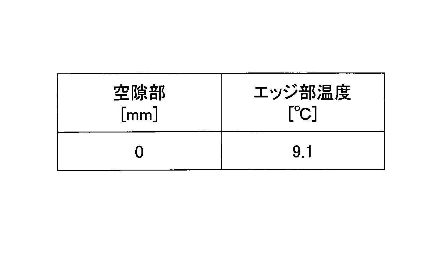
一方、表2に示される通り、比較例における室内側のエッジ部温度は9.1℃であり、実施例1~4よりも0.5℃以上低い温度となり、室外の温度の影響を受け、断熱性が低下していることが分かる。
図21は、実施例1~4及び比較例における空隙部40の距離dと室内側エッジ温度との関係を示した図である。
図21に示されるように、実施例1~4においては、空隙部40における距離dが増加するにつれて、室内側エッジ部の温度が比例的に高くなっている。一方、比較例においては、室内側エッジ部の温度が実施例1~4と比較して大幅に低下していることが分かる。このように、本実施例に係る複層ガラスによれば、複層ガラスの断熱性を高め、室外からの温度の室内への影響を低減できる構成となっていることが示された。
また、室外と室内とを貫流する熱を示す熱貫流率を比較例及び実施例2~4について測定した所、比較例の熱貫流率は4.71(W/m2K)であるのに対し、距離dが3mmの実施例2では4.43(W/m2K)、距離dが5mmの実施例3では4.39(W/m2K)、距離dが7mmの実施例4では4.36(W/m2K)であった。このように、実施例2~4に係る複層ガラスによれば、熱貫流率を比較例に対して0.28~0.35(W/m2K)低下させることができ、断熱性を高めることができることが示された。
また、実験は行っていないが、ガラス板10、11の端面10a、11aからのスペーサ20の距離dが大きくなれば、水の影響を受け難くなり、排水性が向上するのは構造上明らかである。このように、本実施形態に係る複層ガラスによれば、断熱性及び排水性を向上させることができ、これにより、高性能のサッシを提供することができる。
以上、本発明の好ましい実施形態及び実施例について詳説したが、本発明は、上述した実施形態及び実施例に制限されることはなく、本発明の範囲を逸脱することなく、上述した実施形態及び実施例に種々の変形及び置換を加えることができる。
以上、本発明を実施例に基づいて説明したが、本発明は上記実施例に限定されるものではなく、特許請求の範囲に記載の範囲内で様々な変形が可能である。
本願は、日本特許庁に2017年7月18日に出願された基礎出願2017-139033号の優先権を主張するものであり、その全内容を参照によりここに援用する。
10、11 ガラス板
10a、11a 端面
20 スペーサ
20a 外側端面
30 中空層
40 空隙部
50、51 接着剤
60 描画部
70 2次シール
80~84 部材
90~92 保護部材
100 天井
101 床
110、111 サッシ
120 グレージングチャンネル
130 セッティングブロック
10a、11a 端面
20 スペーサ
20a 外側端面
30 中空層
40 空隙部
50、51 接着剤
60 描画部
70 2次シール
80~84 部材
90~92 保護部材
100 天井
101 床
110、111 サッシ
120 グレージングチャンネル
130 セッティングブロック
Claims (18)
- 2枚以上のガラス板が、その間に中空層を形成するようにスペーサを介して対向配置された複層ガラスであって、
前記スペーサは熱可塑性樹脂からなり、
2次シールを有さず、
前記スペーサの端が前記ガラス板の端から1mm以上の所定距離分、前記中空層側に設けられていることを特徴とする複層ガラス。 - 前記所定距離は、3mm以上8mm以下の範囲内にある請求項1に記載の複層ガラス。
- 前記スペーサの端と前記ガラス板の端との間は空間となっている請求項1又は2に記載の複層ガラス。
- 前記スペーサと前記ガラス板とは接着剤を介して接着されており、
前記接着剤の厚さは0.1μm以上50μm以下である請求項1乃至3のいずれか一項に記載の複層ガラス。 - 前記熱可塑性樹脂が、ブチル系ゴムと結晶性ポリオレフィンと乾燥剤と無機フィラーとを含み、ブチル系ゴムと結晶性ポリオレフィンとの合計量に対するブチル系ゴムの割合が50~98重量%、結晶性ポリオレフィンの割合が2~50重量%であり、
前記ブチル系ゴムは、高分子量ブチル系ゴムと低分子量ブチル系ゴムとを含み、
前記高分子量ブチル系ゴムの数平均分子量は55000以上150000以下であり、
前記低分子量ブチル系ゴムの数平均分子量は35000以上50000以下である請求項1乃至4のいずれか一項に記載の複層ガラス。 - 前記スペーサの端面は、凸面である請求項1乃至5のいずれか一項に記載の複層ガラス。
- 前記スペーサの端と前記ガラス板の端との間に形成された凹部の少なくとも一部に、前記スペーサの熱分解温度よりも高い熱分解温度を有する部材または前記スペーサの融点よりも高い融点を有する部材を更に有し、
該部材は、対向配置された少なくとも2枚の前記ガラス板と密着するように設けられた請求項1乃至6のいずれか一項に記載の複層ガラス。 - 前記部材は、温度上昇により膨張する膨張材である請求項7に記載の複層ガラス。
- 前記スペーサの端と前記ガラス板の端との間に形成された凹部の少なくとも一部に、該凹部の深さよりも厚い保護部材を更に有する請求項1乃至6のいずれか一項に記載の複層ガラス。
- 前記保護部材は、少なくとも前記ガラス板の角部に設けられた請求項9に記載の複層ガラス。
- 2枚以上のガラス板が、その間に中空層を形成するようにスペーサを介して対向配置された複層ガラスの製造方法であって、
第1のガラス板の主面に熱可塑性樹脂からなるスペーサを塗布する工程と、
第2のガラス板の主面を、前記第1のガラス板の前記スペーサが塗布された前記主面に対向させ、前記第1のガラス板と前記第2のガラス板とを前記スペーサを介して貼り合わせる工程と、を有し、
前記複層ガラスは、2次シールを有さないことを特徴とする複層ガラスの製造方法。 - 前記スペーサは、前記第1のガラス板の前記主面の端から1mm以上の所定距離分、内側に入った位置に塗布される請求項11に記載の複層ガラスの製造方法。
- 前記所定距離は、3mm以上8mm以下の範囲内にある請求項12に記載の複層ガラスの製造方法。
- 前記スペーサは、前記第1のガラス板の主面に対し上に凸の形状となるように前記第1のガラス板の前記主面に塗布され、
前記第1のガラス板と前記第2のガラス板とを前記スペーサを介して貼り合わせる工程において、前記スペーサの上に凸の部分を押しつぶして前記スペーサが前記第1及び第2のガラス板の面に平行な方向に突出した形状となるように前記第1のガラス板と前記第2のガラス板とを貼り合わせる請求項11乃至13のいずれか一項に記載の複層ガラスの製造方法。 - 前記第1のガラス板の前記主面の端と前記スペーサの端との間は空間である請求項11乃至14のいずれか一項に記載の複層ガラスの製造方法。
- 前記第1のガラス板の前記主面の前記スペーサを塗布する位置に、前記スペーサを塗布する前に接着剤を塗布する工程と、
前記第2のガラス板の前記主面の前記スペーサと貼り合わせる位置に、前記スペーサと貼り合わせる前に接着剤を塗布する工程と、を更に有する請求項11乃至14のいずれか一項に記載の複層ガラスの製造方法。 - 前記第2のガラス板の前記主面に前記接着剤を塗布する工程は、前記第1のガラス板の前記主面に前記スペーサを塗布する工程よりも先に行われる請求項16に記載の複層ガラスの製造方法。
- 前記接着剤は、ノズルを用いて塗布される請求項16又は17に記載の複層ガラスの製造方法。
Priority Applications (1)
| Application Number | Priority Date | Filing Date | Title |
|---|---|---|---|
| JP2019530550A JP7147762B2 (ja) | 2017-07-18 | 2018-07-17 | 複層ガラス及びその製造方法 |
Applications Claiming Priority (2)
| Application Number | Priority Date | Filing Date | Title |
|---|---|---|---|
| JP2017139033 | 2017-07-18 | ||
| JP2017-139033 | 2017-07-18 |
Publications (1)
| Publication Number | Publication Date |
|---|---|
| WO2019017347A1 true WO2019017347A1 (ja) | 2019-01-24 |
Family
ID=65015984
Family Applications (1)
| Application Number | Title | Priority Date | Filing Date |
|---|---|---|---|
| PCT/JP2018/026760 Ceased WO2019017347A1 (ja) | 2017-07-18 | 2018-07-17 | 複層ガラス及びその製造方法 |
Country Status (2)
| Country | Link |
|---|---|
| JP (1) | JP7147762B2 (ja) |
| WO (1) | WO2019017347A1 (ja) |
Cited By (3)
| Publication number | Priority date | Publication date | Assignee | Title |
|---|---|---|---|---|
| JP2022547843A (ja) * | 2019-09-04 | 2022-11-16 | グラストン ジャーマニー ゲゼルシャフト ミット ベシュレンクテル ハフツング | 絶縁ガラスパネルを組み立てるための方法及び装置、及びこのようにして製造された絶縁ガラスパネル |
| JP2022547844A (ja) * | 2019-09-04 | 2022-11-16 | グラストン ジャーマニー ゲゼルシャフト ミット ベシュレンクテル ハフツング | 絶縁ガラスパネルを組み立てるための方法及び装置、及びこのようにして製造された絶縁ガラスパネル |
| WO2024211770A1 (en) * | 2023-04-06 | 2024-10-10 | Corning Incorporated | Glass unit |
Families Citing this family (1)
| Publication number | Priority date | Publication date | Assignee | Title |
|---|---|---|---|---|
| KR102809487B1 (ko) * | 2024-01-26 | 2025-05-21 | 주식회사 에스폴리텍 | 내충격성 및 단열성이 향상된 이중창문 |
Citations (7)
| Publication number | Priority date | Publication date | Assignee | Title |
|---|---|---|---|---|
| WO1997023561A1 (en) * | 1995-12-26 | 1997-07-03 | Asahi Glass Company Ltd. | Resin composition for building materials and double-glazed unit |
| JPH11130475A (ja) * | 1997-10-22 | 1999-05-18 | Central Glass Co Ltd | 複層ガラスおよびその製造方法 |
| JP2002187744A (ja) * | 2000-12-19 | 2002-07-05 | Nippon Sheet Glass Co Ltd | ガラスパネル及びガラスパネルの製造方法 |
| JP2002338310A (ja) * | 2001-05-09 | 2002-11-27 | Nippon Sheet Glass Co Ltd | 複層ガラス |
| WO2005108322A1 (ja) * | 2004-05-07 | 2005-11-17 | Asahi Glass Company, Limited | 単層シール型複層透明体 |
| JP2006273705A (ja) * | 2005-03-30 | 2006-10-12 | Kaneka Corp | 複層ガラス |
| JP2016023484A (ja) * | 2014-07-22 | 2016-02-08 | Ykk Ap株式会社 | 建具 |
Family Cites Families (4)
| Publication number | Priority date | Publication date | Assignee | Title |
|---|---|---|---|---|
| JPS5530980Y2 (ja) * | 1975-12-16 | 1980-07-24 | ||
| US4429509A (en) * | 1981-03-10 | 1984-02-07 | Saint-Gobain Vitrage | Multiple glass pane with improved joints of plastic materials |
| JPH11343150A (ja) * | 1998-05-29 | 1999-12-14 | Central Glass Co Ltd | 複層ガラス |
| JP2003212611A (ja) * | 2002-01-25 | 2003-07-30 | Nippon Sheet Glass Co Ltd | 複層ガラス |
-
2018
- 2018-07-17 JP JP2019530550A patent/JP7147762B2/ja active Active
- 2018-07-17 WO PCT/JP2018/026760 patent/WO2019017347A1/ja not_active Ceased
Patent Citations (7)
| Publication number | Priority date | Publication date | Assignee | Title |
|---|---|---|---|---|
| WO1997023561A1 (en) * | 1995-12-26 | 1997-07-03 | Asahi Glass Company Ltd. | Resin composition for building materials and double-glazed unit |
| JPH11130475A (ja) * | 1997-10-22 | 1999-05-18 | Central Glass Co Ltd | 複層ガラスおよびその製造方法 |
| JP2002187744A (ja) * | 2000-12-19 | 2002-07-05 | Nippon Sheet Glass Co Ltd | ガラスパネル及びガラスパネルの製造方法 |
| JP2002338310A (ja) * | 2001-05-09 | 2002-11-27 | Nippon Sheet Glass Co Ltd | 複層ガラス |
| WO2005108322A1 (ja) * | 2004-05-07 | 2005-11-17 | Asahi Glass Company, Limited | 単層シール型複層透明体 |
| JP2006273705A (ja) * | 2005-03-30 | 2006-10-12 | Kaneka Corp | 複層ガラス |
| JP2016023484A (ja) * | 2014-07-22 | 2016-02-08 | Ykk Ap株式会社 | 建具 |
Cited By (3)
| Publication number | Priority date | Publication date | Assignee | Title |
|---|---|---|---|---|
| JP2022547843A (ja) * | 2019-09-04 | 2022-11-16 | グラストン ジャーマニー ゲゼルシャフト ミット ベシュレンクテル ハフツング | 絶縁ガラスパネルを組み立てるための方法及び装置、及びこのようにして製造された絶縁ガラスパネル |
| JP2022547844A (ja) * | 2019-09-04 | 2022-11-16 | グラストン ジャーマニー ゲゼルシャフト ミット ベシュレンクテル ハフツング | 絶縁ガラスパネルを組み立てるための方法及び装置、及びこのようにして製造された絶縁ガラスパネル |
| WO2024211770A1 (en) * | 2023-04-06 | 2024-10-10 | Corning Incorporated | Glass unit |
Also Published As
| Publication number | Publication date |
|---|---|
| JP7147762B2 (ja) | 2022-10-05 |
| JPWO2019017347A1 (ja) | 2020-05-28 |
Similar Documents
| Publication | Publication Date | Title |
|---|---|---|
| CN106715819B (zh) | 用于隔热装配玻璃的间隔件 | |
| WO2019017347A1 (ja) | 複層ガラス及びその製造方法 | |
| CN104011313B (zh) | 用于绝热窗用玻璃单元的间隔件 | |
| US8402716B2 (en) | Encapsulated composit fibrous aerogel spacer assembly | |
| US20160290032A1 (en) | Spacer for insulating glazing units, comprising extruded profiled seal | |
| KR102567521B1 (ko) | 보강 요소를 갖는 스페이서 | |
| KR20160047539A (ko) | 절연 글레이징 유닛용 스페이서 | |
| US9803415B2 (en) | Spacer for insulating glazing unit | |
| JP2023503705A (ja) | 向上した接着性を有するスペーサ | |
| CN114981076A (zh) | 包括中断的粘附层的间隔件 | |
| WO2020118682A1 (zh) | 玻璃复合边框支撑合片双胶粘接密封不锈钢边框中空玻璃 | |
| CN102438827B (zh) | 层叠窗玻璃 | |
| CA3142978C (en) | Spacer for insulated glass units | |
| CN211230074U (zh) | 真空有机膜复合中空玻璃 | |
| JP4363616B2 (ja) | 複層ガラス | |
| US12516565B2 (en) | Heat-insulating glass panel | |
| JP6431291B2 (ja) | 建材パネルとその製造方法 | |
| JP3128529U (ja) | 複層ガラス | |
| CN110685554A (zh) | 真空有机膜复合中空玻璃 | |
| US20240286386A1 (en) | Fire-resistant glazing | |
| JP6529423B2 (ja) | 複層ガラス用スペーサーおよび複層ガラス | |
| CN117441053A (zh) | 具有共挤出中空型材的间隔件 | |
| JP7387287B2 (ja) | 断熱構造体、及び板状断熱材 | |
| JP2020045759A (ja) | グレージングチャンネル付き複層ガラス及びその製造方法 | |
| KR20150006120A (ko) | 진공 유리 |
Legal Events
| Date | Code | Title | Description |
|---|---|---|---|
| 121 | Ep: the epo has been informed by wipo that ep was designated in this application |
Ref document number: 18835163 Country of ref document: EP Kind code of ref document: A1 |
|
| ENP | Entry into the national phase |
Ref document number: 2019530550 Country of ref document: JP Kind code of ref document: A |
|
| NENP | Non-entry into the national phase |
Ref country code: DE |
|
| 122 | Ep: pct application non-entry in european phase |
Ref document number: 18835163 Country of ref document: EP Kind code of ref document: A1 |