WO2019017293A1 - 発泡成形用の射出成形機 - Google Patents
発泡成形用の射出成形機 Download PDFInfo
- Publication number
- WO2019017293A1 WO2019017293A1 PCT/JP2018/026509 JP2018026509W WO2019017293A1 WO 2019017293 A1 WO2019017293 A1 WO 2019017293A1 JP 2018026509 W JP2018026509 W JP 2018026509W WO 2019017293 A1 WO2019017293 A1 WO 2019017293A1
- Authority
- WO
- WIPO (PCT)
- Prior art keywords
- stage
- resin
- screw
- inert gas
- molding machine
- Prior art date
- Legal status (The legal status is an assumption and is not a legal conclusion. Google has not performed a legal analysis and makes no representation as to the accuracy of the status listed.)
- Ceased
Links
Images

Classifications
-
- B—PERFORMING OPERATIONS; TRANSPORTING
- B29—WORKING OF PLASTICS; WORKING OF SUBSTANCES IN A PLASTIC STATE IN GENERAL
- B29C—SHAPING OR JOINING OF PLASTICS; SHAPING OF MATERIAL IN A PLASTIC STATE, NOT OTHERWISE PROVIDED FOR; AFTER-TREATMENT OF THE SHAPED PRODUCTS, e.g. REPAIRING
- B29C45/00—Injection moulding, i.e. forcing the required volume of moulding material through a nozzle into a closed mould; Apparatus therefor
- B29C45/17—Component parts, details or accessories; Auxiliary operations
- B29C45/18—Feeding the material into the injection moulding apparatus, i.e. feeding the non-plastified material into the injection unit
- B29C45/1816—Feeding auxiliary material, e.g. colouring material
-
- B—PERFORMING OPERATIONS; TRANSPORTING
- B29—WORKING OF PLASTICS; WORKING OF SUBSTANCES IN A PLASTIC STATE IN GENERAL
- B29C—SHAPING OR JOINING OF PLASTICS; SHAPING OF MATERIAL IN A PLASTIC STATE, NOT OTHERWISE PROVIDED FOR; AFTER-TREATMENT OF THE SHAPED PRODUCTS, e.g. REPAIRING
- B29C45/00—Injection moulding, i.e. forcing the required volume of moulding material through a nozzle into a closed mould; Apparatus therefor
- B29C45/17—Component parts, details or accessories; Auxiliary operations
- B29C45/46—Means for plasticising or homogenising the moulding material or forcing it into the mould
- B29C45/58—Details
- B29C45/60—Screws
-
- B—PERFORMING OPERATIONS; TRANSPORTING
- B29—WORKING OF PLASTICS; WORKING OF SUBSTANCES IN A PLASTIC STATE IN GENERAL
- B29C—SHAPING OR JOINING OF PLASTICS; SHAPING OF MATERIAL IN A PLASTIC STATE, NOT OTHERWISE PROVIDED FOR; AFTER-TREATMENT OF THE SHAPED PRODUCTS, e.g. REPAIRING
- B29C45/00—Injection moulding, i.e. forcing the required volume of moulding material through a nozzle into a closed mould; Apparatus therefor
-
- B—PERFORMING OPERATIONS; TRANSPORTING
- B29—WORKING OF PLASTICS; WORKING OF SUBSTANCES IN A PLASTIC STATE IN GENERAL
- B29C—SHAPING OR JOINING OF PLASTICS; SHAPING OF MATERIAL IN A PLASTIC STATE, NOT OTHERWISE PROVIDED FOR; AFTER-TREATMENT OF THE SHAPED PRODUCTS, e.g. REPAIRING
- B29C45/00—Injection moulding, i.e. forcing the required volume of moulding material through a nozzle into a closed mould; Apparatus therefor
- B29C45/17—Component parts, details or accessories; Auxiliary operations
- B29C45/46—Means for plasticising or homogenising the moulding material or forcing it into the mould
- B29C45/47—Means for plasticising or homogenising the moulding material or forcing it into the mould using screws
- B29C45/50—Axially movable screw
-
- B—PERFORMING OPERATIONS; TRANSPORTING
- B29—WORKING OF PLASTICS; WORKING OF SUBSTANCES IN A PLASTIC STATE IN GENERAL
- B29C—SHAPING OR JOINING OF PLASTICS; SHAPING OF MATERIAL IN A PLASTIC STATE, NOT OTHERWISE PROVIDED FOR; AFTER-TREATMENT OF THE SHAPED PRODUCTS, e.g. REPAIRING
- B29C45/00—Injection moulding, i.e. forcing the required volume of moulding material through a nozzle into a closed mould; Apparatus therefor
- B29C45/17—Component parts, details or accessories; Auxiliary operations
- B29C45/46—Means for plasticising or homogenising the moulding material or forcing it into the mould
- B29C45/58—Details
- B29C45/63—Venting or degassing means
-
- B—PERFORMING OPERATIONS; TRANSPORTING
- B29—WORKING OF PLASTICS; WORKING OF SUBSTANCES IN A PLASTIC STATE IN GENERAL
- B29C—SHAPING OR JOINING OF PLASTICS; SHAPING OF MATERIAL IN A PLASTIC STATE, NOT OTHERWISE PROVIDED FOR; AFTER-TREATMENT OF THE SHAPED PRODUCTS, e.g. REPAIRING
- B29C45/00—Injection moulding, i.e. forcing the required volume of moulding material through a nozzle into a closed mould; Apparatus therefor
- B29C45/17—Component parts, details or accessories; Auxiliary operations
- B29C45/1701—Component parts, details or accessories; Auxiliary operations using a particular environment during moulding, e.g. moisture-free or dust-free
- B29C2045/1702—Component parts, details or accessories; Auxiliary operations using a particular environment during moulding, e.g. moisture-free or dust-free dissolving or absorbing a fluid in the plastic material
-
- B—PERFORMING OPERATIONS; TRANSPORTING
- B29—WORKING OF PLASTICS; WORKING OF SUBSTANCES IN A PLASTIC STATE IN GENERAL
- B29C—SHAPING OR JOINING OF PLASTICS; SHAPING OF MATERIAL IN A PLASTIC STATE, NOT OTHERWISE PROVIDED FOR; AFTER-TREATMENT OF THE SHAPED PRODUCTS, e.g. REPAIRING
- B29C45/00—Injection moulding, i.e. forcing the required volume of moulding material through a nozzle into a closed mould; Apparatus therefor
- B29C45/17—Component parts, details or accessories; Auxiliary operations
- B29C45/1703—Introducing an auxiliary fluid into the mould
- B29C45/1704—Introducing an auxiliary fluid into the mould the fluid being introduced into the interior of the injected material which is still in a molten state, e.g. for producing hollow articles
- B29C2045/1722—Introducing an auxiliary fluid into the mould the fluid being introduced into the interior of the injected material which is still in a molten state, e.g. for producing hollow articles injecting fluids containing plastic material
-
- B—PERFORMING OPERATIONS; TRANSPORTING
- B29—WORKING OF PLASTICS; WORKING OF SUBSTANCES IN A PLASTIC STATE IN GENERAL
- B29C—SHAPING OR JOINING OF PLASTICS; SHAPING OF MATERIAL IN A PLASTIC STATE, NOT OTHERWISE PROVIDED FOR; AFTER-TREATMENT OF THE SHAPED PRODUCTS, e.g. REPAIRING
- B29C45/00—Injection moulding, i.e. forcing the required volume of moulding material through a nozzle into a closed mould; Apparatus therefor
- B29C45/17—Component parts, details or accessories; Auxiliary operations
- B29C45/46—Means for plasticising or homogenising the moulding material or forcing it into the mould
- B29C45/58—Details
- B29C45/60—Screws
- B29C2045/605—Screws comprising a zone or shape enhancing the degassing of the plastic material
-
- B—PERFORMING OPERATIONS; TRANSPORTING
- B29—WORKING OF PLASTICS; WORKING OF SUBSTANCES IN A PLASTIC STATE IN GENERAL
- B29C—SHAPING OR JOINING OF PLASTICS; SHAPING OF MATERIAL IN A PLASTIC STATE, NOT OTHERWISE PROVIDED FOR; AFTER-TREATMENT OF THE SHAPED PRODUCTS, e.g. REPAIRING
- B29C44/00—Shaping by internal pressure generated in the material, e.g. swelling or foaming ; Producing porous or cellular expanded plastics articles
-
- B—PERFORMING OPERATIONS; TRANSPORTING
- B29—WORKING OF PLASTICS; WORKING OF SUBSTANCES IN A PLASTIC STATE IN GENERAL
- B29K—INDEXING SCHEME ASSOCIATED WITH SUBCLASSES B29B, B29C OR B29D, RELATING TO MOULDING MATERIALS OR TO MATERIALS FOR MOULDS, REINFORCEMENTS, FILLERS OR PREFORMED PARTS, e.g. INSERTS
- B29K2105/00—Condition, form or state of moulded material or of the material to be shaped
- B29K2105/04—Condition, form or state of moulded material or of the material to be shaped cellular or porous
Definitions
- the present invention relates to an injection molding machine used for a method of molding a foam molded article, wherein an inert gas is injected into a molten resin and injected into a mold to obtain a foam molded article.
- foam molded articles having a large number of fine cells formed therein, ie, foam molded articles are not only lightweight but also excellent in strength, and the application field is wide.
- foaming agents so-called chemical blowing agents which are thermally decomposed to generate gas are also used, but physical blowing agents consisting of inert gas are also used. Nitrogen and carbon dioxide are relatively often used as physical blowing agents.
- Such an inert gas is injected at a predetermined pressure into the resin melted in the heating cylinder, and the resin is kneaded to dissolve the inert gas in the resin.
- Patent Document 1 describes an injection molding machine for obtaining a foam-molded article with a physical blowing agent comprising an inert gas.
- the injection molding machine 50 will be described with reference to FIG.
- the injection molding machine 50 comprises a heating cylinder 51 and a screw 52 provided in the heating cylinder 51 so as to be drivable in the rotational direction and in the axial direction.
- the screw 52 has two compression parts where the screw groove is shallow, that is, the first and second compression parts 54 and 56 are formed, and a deep starvation of the screw groove is generated between the first and second compression parts 54 and 56 A portion 55 is formed.
- the heating cylinder 51 is provided with an inert gas injection portion 57 corresponding to the starvation portion 55 so that the inert gas 58 is injected.
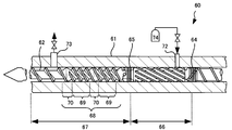
- Patent Document 2 describes an injection molding machine 60 that can inject a surface modifying substance such as a metal complex into a molten resin, knead it, and inject it.
- the injection molding machine 60 is comprised from the heating cylinder 61 and the screw 62, as FIG. 5 shows.
- the screw 62 is provided with first and second seal structures 64 and 65 at predetermined positions. A high pressure area 66 and a low pressure area 67 are formed in the screw 62 by the first and second seal structures 64 and 65.
- the first seal structure 64 has a predetermined valve structure so that the resin sent from the rear of the screw 62 to the front is sent to the high pressure area 66, but the back flow from the high pressure area 66 is prevented. It is done.
- the second seal structure 65 has a valve structure that is opened and closed by the rotation direction of the screw 62. When the valve structure of the second seal structure 65 is closed, the high pressure area 66 and the low pressure area 67 are shut off and the resin can not flow, but when open, the resin can flow freely.
- the screw 62 is provided with a step-down relief section 68 downstream of the second seal structure 65 in the low pressure area 67.
- deep groove portions 69 and shallow shallow groove portions 70 are alternately formed with deep screw grooves between flights, and at least two shallow groove portions 70, 70 are formed in the axial direction.
- the throttling action is exerted in the shallow groove portions 70 and 70, and when the resin flows from the high pressure area 66 to the low pressure area 67, the pressure is appropriately lowered.
- the heating cylinder 61 is provided with an inlet 72 for injecting an inert gas or the like corresponding to the high pressure area 66, and an outlet 73 for discharging the inert gas to the downstream side of the step-down alleviation section 68 of the low pressure area 67. It is provided.
- the second seal structure 65 is opened, and the molten resin flows from the high pressure area 66 to the low pressure area 67. However, the pressure is gradually reduced by the pressure reduction relaxation section 68. An inert gas is generated from the molten resin, and the inert gas is degassed from the outlet 73. When the molten resin to which the surface modifying substance is added is injected into a mold, a desired molded product is obtained.
- the injection molding machine 60 provided with the screw 62 described in Patent Document 2 can also be used for a method of molding a foam molded product using a physical foaming agent, that is, an inert gas.
- a physical foaming agent that is, an inert gas.
- the inert gas is injected, for example, at 10 MPa.
- the inert gas is sufficiently dispersed and permeated into the molten resin in the high pressure area 66 and then sent to the low pressure area 67.
- the valve provided at the discharge port 73 is controlled so that the pressure in the heating cylinder 61 becomes about 5 MPa.
- the injection molding machines 50 and 60 described in Patent Documents 1 and 2 can inject an inert gas into a molten resin appropriately to form a foam-molded article, but there are also problems to be solved for each.
- the screw 52 Since the screw 52 is made to stop its rotation at least at the time of injection, it is difficult to completely prevent the backflow of the inert gas, and there is a problem that the molding cycle can not be stably performed. Further, in the injection molding machine 50 described in Patent Document 1, there is also a problem that the penetration and mixing of the inert gas into the molten resin become insufficient.
- the inert gas is injected into the starved part 55, and the inert gas penetrates the molten resin only in the vicinity of the second compression part 56. In other words, the inert gas has to be permeated over a relatively short distance. In this case, the inert gas may not permeate the molten resin sufficiently and uniformly.
- An object of the present invention is to provide an injection molding machine for foam molding which solves the above-mentioned problems, specifically, a physical blowing agent comprising an inert gas is injected into a molten resin to foam the foam.
- a physical blowing agent comprising an inert gas is injected into a molten resin to foam the foam.
- the present invention is directed to a foam injection molding machine in which the heating cylinder is divided into a rear first stage and a front second stage according to the shape of the screw.
- the first stage forms a first compression section for compressing the resin
- the second stage forms a starvation section for reducing the pressure of the resin and a second compression section for compressing the resin.
- Inert gas is injected in this starvation zone.
- the screw is provided with a predetermined seal structure that prevents backflow of the resin and the inert gas at the boundary between the first and second stages.
- the flight in the second stage is configured to be a multi-row flight with two or more lines and to have a lead angle in the range of 10 to 45 degrees.
- the invention according to claim 1 is an injection molding machine comprising a heating cylinder and a screw provided rotatably in the rotational direction and in the axial direction in the heating cylinder,
- the heating cylinder is divided into a rear first stage and a front second stage according to the shape of the screw, and the first stage is provided with a first compression section for compressing a resin,
- a starvation section for reducing the pressure of the resin and a second compression section for compressing the resin are respectively formed, and the heating cylinder is injected with a gas for injecting an inert gas at a position corresponding to the starvation section.
- a hole is provided, and the screw is provided with a predetermined seal structure for preventing backflow of the resin and the inert gas at the boundary between the first and second stages, and the second stage is provided with the seal structure.
- Kicking flight is configured as an injection molding machine for foam molding, wherein the lead angle is in the range of 10 to 45 degrees with has two or more strips of a multi-strip flight.
- the invention according to claim 2 is the injection molding machine according to claim 1, wherein the screw is provided with a step-down relief section adjacent to the seal structure in the second stage, and the step-down relief section is a flight.
- a shallow groove is formed in at least two places in the axial direction at least in the axial direction, and the screw groove between them is formed as an injection molding machine for foam molding.
- the invention according to claim 3 is the injection molding machine according to claim 1 or 2, wherein the gas supply hole is provided with an opening and closing mechanism, and is configured as an injection molding machine for foam molding.
- the invention according to claim 4 is the injection molding machine according to any one of claims 1 to 3, wherein two or more of the gas supply holes are provided at predetermined intervals in the axial direction in the heating cylinder. It is configured as an injection molding machine for foam molding characterized by
- the invention according to claim 5 is the injection molding machine according to any one of claims 1 to 4, characterized in that the heating cylinder is provided with a resin pressure sensor corresponding to the starvation zone. It is configured as an injection molding machine for foam molding.
- the present invention is directed to an injection molding machine for foam molding, and the heating cylinder is divided into a rear first stage and a front second stage according to the shape of the screw, and the first stage
- the first compression section for compressing the resin, the starvation section for reducing the pressure of the resin and the second compression section for compressing the resin are formed in the second stage, and the heating cylinder is in the starvation section.
- Gas injection holes are provided at corresponding locations for injecting an inert gas. That is, in the injection molding machine targeted by the present invention, the resin is melted and compressed in the first stage, sent to the second stage, and the inert gas is injected in the starvation section in the second stage. It has become.
- the screw is provided with a predetermined seal structure which prevents the backflow of the resin and the inert gas at the boundary between the first and second stages. If rotation of the screw is stopped, there is a risk that the resin into which the inert gas has been injected may reverse flow, but since the seal structure is provided, reverse flow from the second stage to the first stage is completely prevented. In particular, backflow is likely to occur when the rotation of the screw is stopped as in injection, but the seal structure can prevent backflow with certainty.
- the flight at the second stage is a multi-row flight with two or more lines and a lead angle in the range of 10 to 45 degrees.
- the resin into which the inert gas has been injected is to be kneaded in the second stage, but since it is a multi-row flight in the second stage, it is to be kneaded efficiently and uniformly.
- the inert gas sufficiently and uniformly penetrates the resin to form a foam molded product of excellent quality.
- an inert gas is injected in the starvation zone, in order to sufficiently reduce the pressure of the resin in the starvation zone, it is necessary that the transport amount of the resin be large in the second stage.
- the flight of the second stage is selected to have a lead angle in the range of 10 to 45 degrees, the transport amount of the resin is increased, and the pressure of the resin in the starved section can be reliably reduced. This will allow sufficient inert gas injection.
- the screw is provided with a step-down relief section adjacent to the seal structure in the second stage, and in the step-down relief section, at least two shallow groove portions with shallow screw grooves between flights are formed in the axial direction. ing. According to the present invention, since the step-down relaxation section is provided, the effect of stably injecting the inert gas can be obtained.
- the gas supply hole is provided with an open / close mechanism. By opening and closing the gas supply holes as required, it is possible to prevent the resin from rising in the gas supply holes.
- two or more gas supply holes are provided in the heating cylinder at predetermined intervals in the axial direction.
- the screw retracts, and thereby the starvation section also retracts.
- the screw since two or more gas supply holes are provided at predetermined intervals in the axial direction, the screw retracted position
- the heating cylinder is provided with a resin pressure sensor corresponding to the starvation zone. The inert gas is injected in the starvation zone, but when the gas injection hole is blocked by the resin, the pressure detected by the resin pressure sensor becomes larger than the pressure of the inert gas. In the present invention, such an abnormality can be detected promptly.
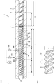
- the (A) is front sectional drawing of an injection molding machine
- the (B) shows the screw of the 2nd stage of a screw. It is a front view.
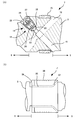
- the (A) and the (B) respectively make the seal structure which concerns on a respectively different embodiment parallel to the axis of a screw
- the injection molding machine 1 is, as shown in FIG. 1, a heating cylinder 2 and a screw provided in the heating cylinder 2 so as to be drivable in the rotational direction and in the axial direction. It consists of three. A plurality of band heaters are wound around the outer peripheral surface of the heating cylinder 2, but these are not shown in the figure.
- the inside of the heating cylinder 2 is roughly divided into two sections depending on the shape of the screw 3. That is, the first stage 5 at the rear and the second stage 6 at the front.
- the first stage 5 is a section in which the resin is melted
- the second stage 6 is a section in which the inert gas is injected and the inert gas penetrates into the resin.
- the first and second stages 5 and 6 are divided by the seal structure 7 according to the present embodiment. That is, it can be said that the inside of the heating cylinder 2 is divided into the first and second stages 5 and 6 by the seal structure 7.
- the point in which such a seal structure 7 is provided is one of the features of the injection molding machine 1 according to the present embodiment, and the seal structure 7 according to the present embodiment will be described in detail later.
- the flight of the screw 3 is different between the first stage 5 and the second stage 6.
- the number of flights is different. That is, the first stage 5 consists of a single flight of a general pitch and a lead, while the second stage 6 consists of a multi-row flight.
- the point in which the second stage 6 is composed of multiple flights is also one of the features of the injection molding machine 1 according to the present embodiment. Since the second stage 6 has a large number of flights, the resin to be delivered is smoothly delivered downstream without disturbance or reverse flow even if the viscosity is small.
- the second stage 6 is a stage in which the inert gas is injected, but the resin is discharged smoothly while being appropriately kneaded by the multi-row flight so that the inert gas uniformly and sufficiently penetrates into the resin become.
- the multi-row flight of the second stage 6 has no notch. If the notch is provided, the kneading performance will be improved, but since the backflow occurs at the notch portion, the feeding ability of the resin is somewhat sacrificed.
- the second stage 6 is composed of two flights in the present embodiment, but may be composed of not only two flights but also three flights or many flights of more than that.
- the first stage 5 is composed of a single flight as described above, but in the vicinity of the hopper not shown in the figure, the screw groove between the flights is relatively deep, and the screw groove is shallow near the front
- the first compression section 8 is performed. Accordingly, in the vicinity of the hopper, the resin can be smoothly fed forward while being melted, and in the first compression section 8, the resin is completely melted and compressed.
- the compressed resin is sent to the second stage 6 via the seal structure 7.
- the depth of the screw groove is changed in the second stage 6 as well, whereby a plurality of sections are formed in the axial direction.
- the step-down alleviation section 11 is formed adjacent to the seal structure 7.
- the step-down relief section 11 is also one of the features of the injection molding machine 1 according to the present embodiment, and will be described next.
- a screw groove is formed and a deep starvation zone 9 is formed.
- the screw groove is deep and the volume in the heating cylinder 2 is large, so the pressure of the resin decreases. Therefore, a physical blowing agent consisting of an inert gas is injected in this section 9 as will be described later.
- a second compression section 10 in which the screw groove is shallow and the resin is compressed is formed on the second stage 6 in front of or in the downstream of the starvation section 9.
- the inert gas sufficiently and uniformly penetrates into the resin.
- the step-down relaxation section 11 which is a characteristic structure in the present embodiment will be described.
- the flight of the step-down relaxation section 11 is also composed of two flights as in the other sections of the second stage 6, but the deep groove portions 12, 12 with deep screw grooves and the shallow shallow groove portions 13, 13 are in the axial direction Are formed in at least two places. That is, the shallow groove portions 13, 13 are formed in two or more places at predetermined intervals in the axial direction.
- a throttling action is generated by the shallow groove portions 13 and 13, and when the resin is fed in the step-down relief section 11, the pressure can be gradually dropped. Therefore, the resin pressure can be reliably reduced in the starvation zone 9.
- the throttling action of the shallow groove portions 13, 13 also has an effect of preventing the molten resin containing the inert gas from backflowing when the rotation of the screw 3 is stopped.
- the lead angle ⁇ of the flight is selected in a predetermined range, so the flow rate for sending out the resin is large.
- the lead angle ⁇ is selected to be 10 to 45 degrees, preferably 10 to 40 degrees, and more preferably 20 to 35 degrees.
- the flow rate can be sufficiently increased in the second compression section 10, and thereby the pressure of the resin can be reliably reduced in the starvation section 9.
- the reason why the lead angle ⁇ is selected in such a range will be described.
- the flow rate Q of the resin axially fed by the screw 3 is given by the following equation.
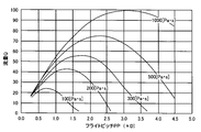
- the flow rate Q varies with the viscosity ⁇ of the resin, but for the resin of various viscosities, the flow rate Q when the flight lead angle etc. is changed is calculated according to the above equation, and this is the graph of FIG. Shown in.
- the horizontal axis is the pitch PP, but the pitch PP is the screw diameter D ⁇ ⁇ ⁇ cos ⁇ / number of flight threads p.
- the flow rate Q changes depending on the viscosity ⁇ of the resin, the flow rate is relatively large when the pitch is in the range of 0.5D to ⁇ D. That is, when the lead angle ⁇ is in the range of 10 to 45 degrees, the flow rate is relatively large.
- the screw 3 selects the lead angle ⁇ in the above-described range.
- the seal structure 7 provided in the screw 3 according to the present embodiment comprises a seal 15 and a flow control mechanism 16 that exerts a pressure adjustment function. .
- the seal 15 is slidably fitted in a predetermined groove formed on the outer peripheral surface of the screw 3.
- the heating cylinder 2 is not shown in FIG. 2A, the outer peripheral surface of the seal 15 is in sliding contact with the bore of the heating cylinder 2 in a smooth manner.
- the molten resin is prevented from flowing in the seal 15, and the inside of the heating cylinder 2 is partitioned in a fluid-tight manner into the upstream first stage 5 and the downstream second stage 6.
- the seal structure 7 is provided with one or more flow control mechanisms 16.
- the flow control mechanism 16 includes a communication passage 18 opened in the screw 3 so as to communicate the first stage 5 and the second stage 6 and a valve mechanism 19 for opening and closing the communication passage 18. ing.
- the communication passage 18 is tapered at its midway portion, whereby a tapered seating surface 20 is formed.
- the poppet valve 22 includes an umbrella-like head 23 and a shaft 24.
- the shaft 24 is provided with a plurality of disc springs 26, 26,. As described above, the poppet valve 22 provided with the disc springs 26, 26,... Is inserted in the retainer 27 in which the bottomed hole is opened.
- the retainer 27 is screwed and fixed to the female screw formed on the inner peripheral surface of the communication passage 18 by the male screw formed on the outer peripheral surface thereof. Accordingly, the poppet valve 22 is biased by the disc springs 26, 26,... So that the head 23 is pressed against the seating surface 20 and the communication passage 18 is closed.
- the poppet valve 22 retracts against the biasing force of the disc springs 26, 26, ..., and the first stage 5 and the second stage 6 Communicate and the molten resin flows to the second stage 6, that is, to the step-down relief section 11.
- the resin passage 28 is opened in the retainer 27 and the molten resin flows from the resin passage 28 to the step-down relief section 11 when the first stage 5 and the second stage 6 communicate with each other.
- the poppet valve 22 Since the seat is closed and the communication is shut off, the backflow of the molten resin is completely prevented.
- the injection molding machine 1 is, as shown in FIG. 1, two injection parts for injecting an inert gas at a position corresponding to the starvation section 9 in the heating cylinder 2, that is, the first and second injection parts.
- Injectors 29A and 29B are provided.
- the first and second injection parts 29A and 29B are provided at predetermined intervals in the axial direction, and the pipes from the gas cylinder 31 containing inert gas are connected via the on-off valve 32A. .
- an inert gas such as nitrogen or carbon dioxide is injected into the heating cylinder 2 from the first and second injection portions 29A and 29B.
- the injection molding machine 1 is thus provided with two injection parts 29A, 29B in the axial direction, the screw 3 is retracted in the measurement of the resin and the position of the starvation section 9 is in the axial direction Even if it moves to, either injection
- the first and second injection parts 29A, 29B are provided with an on-off valve consisting of a needle valve at a position close to the bore of the heating cylinder 2, and the screw 3 is moved in the axial direction at the time of measurement. When the injectors 29A, 29B are removed from the starvation zone 9, the needle valve is closed to prevent the resin from entering the first and second injectors 29A, 29B.
- a resin pressure sensor 33 is provided at a position corresponding to the starvation section 9 in the heating cylinder 2. Since the pressure of the resin becomes substantially atmospheric pressure in the starvation zone 9, the pressure detected by the resin pressure sensor 33 becomes the pressure of the inert gas when the inert gas is injected. The pressure detected by the resin pressure sensor 33 is monitored, and when it becomes larger than the pressure of the inert gas supplied from the gas cylinder 31, it is determined that the opening of the first and second injection parts 29A and 29B is closed by the resin. It is possible to determine the abnormality.
- the heating cylinder 2 is heated to rotate the screw 3 in the forward direction, and the resin material is supplied from a hopper not shown.
- the supplied resin material is melted by the heat of the heating cylinder 2 and the heat due to the shear force of the rotation of the screw 3, and the first stage 5 is sent forward to be compressed in the first compression section 8. Since the pressure of the molten resin in the first compression section 8 is large, the poppet valve 22 opens in the seal structure 7 and the molten resin is sent to the step-down relief section 11 of the second stage 6. Then, the molten resin is sent to the starvation zone 9 through the pressure reduction relaxation zone 11.
- Such molten resin is compressed at the second stage 6 and metered to the head of the screw 3.
- the rotation of the screw 3 is stopped.
- the screw 3 is driven in the axial direction to inject the molten resin into the mold.
- the inert gas bubbles in the molten resin to obtain a foam-molded article.
- FIG. 2B shows a seal structure 7 'according to another embodiment.
- the seal structure 7 'according to this embodiment includes a diameter-reduced portion 35 obtained by reducing the diameter of the screw 3 and a seal ring 36 provided in the diameter-reduced portion 35 with a predetermined gap.
- the outer peripheral surface of the seal ring 36 is in smooth contact with the bore of the heating cylinder 2 so that the molten resin does not flow from the outer peripheral surface. That is, the inside of the heating cylinder 2 is partitioned in a fluid-tight manner by the seal ring 36 into the upstream first stage 5 and the downstream second stage 6.
- the diameter reducing portion 35 in which the seal ring 36 is fitted with a gap is enlarged at the upstream side thereof to form a tapered surface 37, and the upstream end of the seal ring 36 is also formed in a tapered shape. ing.
- an abutting portion 38 with which the seal ring 36 abuts is formed.
- the tapered end of the seal ring 36 is separated from the tapered surface 37 and the first stage 5 and the second stage 6 are interposed between the reduced diameter portion 35 and the inner circumferential surface of the seal ring 36. Communicate and the molten resin flows downstream.
- a predetermined notch is formed on the end face of the seal ring 36 so that a flow path of the molten resin can be secured even when the seal ring 36 abuts on the contact portion 38.
- the pressure of the molten resin of the second stage 6 becomes larger than the pressure of the first stage 5. Then, the seal ring 36 is seated on the tapered surface 37, the communication is blocked, and the flow of the molten resin is inhibited. That is, backflow is prevented.
- the flight of the first stage 5 can also be modified, and is not limited to a single flight.
- the number and shape of flight threads can be appropriately changed according to the type of resin used, the size of the apparatus, and the like.
- the inert gas injection parts 29A and 29B can be modified. First, the number can be modified, and only one may be provided, or three or more may be provided.
- the opening and closing states of the inert gas injection parts 29A and 29B may be modified, and either one may be always open, for example, the opening may be limited during plasticization, etc. Only a predetermined process may be performed.
- the on-off valves 32A and 32B are not necessarily required for the inert gas injection parts 29A and 29B.
- a check valve may be provided for the inert gas inlets 29A and 29B. Since the check valve automatically opens and closes according to the resin pressure, when the injection sections 29A, 29B move out of the staring section 9 or the resin pressure in the heating cylinder 2 increases, the backflow of resin from the injection sections 29A, 29B You can prevent.
- the resin pressure sensor 33 can also be modified, and two or more may be provided.
Landscapes
- Engineering & Computer Science (AREA)
- Manufacturing & Machinery (AREA)
- Mechanical Engineering (AREA)
- Injection Moulding Of Plastics Or The Like (AREA)
- Molding Of Porous Articles (AREA)
Abstract
【課題】機械長が短くても、不活性ガスの逆流が防止され、安定的に品質が高い発泡成形品を成形することができる射出成形機のスクリュを提供する。 【解決手段】加熱シリンダ(2)が、スクリュ(3)の形状に従って第1のステージ(5)と第2のステージ(6)とに区分されている発泡成形用の射出成形機を対象とする。第1のステージ(5)には樹脂を圧縮する第1の圧縮区間(8)を、そして第2のステージ(6)には樹脂の圧力を低下させる飢餓区間(9)と樹脂を圧縮する第2の圧縮区間(10)とを形成する。この飢餓区間(9)において不活性ガスが注入されるようにする。スクリュ(3)は、第1、2のステージ(5、6)の境界において樹脂と不活性ガスの逆流を防止する所定のシール構造(7)を設ける。第2のステージ(6)におけるフライトは2条以上の多条フライトにすると共にリード角が10~45度の範囲になるように構成する。
Description
本発明は、溶融樹脂に不活性ガスを注入して金型に射出し発泡成形品を得る、発泡成形品の成形方法に使用される射出成形機に関するものである。
内部に微細な気泡が多数形成されている成形品すなわち発泡成形品は、軽量であるだけでなく強度にも優れており、応用分野は広い。射出成形により発泡成形品を得るには発泡剤を樹脂に混入させる必要がある。発泡剤には熱分解されて気体が発生するいわゆる化学発泡剤も利用されているが、不活性ガスからなる物理発泡剤も利用されている。物理発泡剤として、窒素、二酸化炭素が比較的多く利用されている。加熱シリンダ内で溶融した樹脂に、このような不活性ガスを所定の圧力で注入し、樹脂を混練して樹脂中に不活性ガスを溶け込むようにする。これを金型に射出すると、樹脂中で圧力が解放されて不活性ガスが気泡化する。樹脂が冷却固化すると発泡成形品が得られる。不活性ガスからなる物理発泡剤は高圧かつ高温で樹脂に注入されるので浸透力が強く、樹脂中に均一に分散し易い。従って得られる発泡成形品において発泡ムラが発生しにくいという優れた特徴がある。
特許文献1には、不活性ガスからなる物理発泡剤により発泡成形品を得る射出成形機が記載されている。この射出成形機50を図4によって説明する。射出成形機50は加熱シリンダ51と、この加熱シリンダ51内で回転方向と軸方向とに駆動可能に設けられているスクリュ52とからなる。スクリュ52は、スクリュ溝が浅くなっている2箇所の圧縮部、つまり第1、2の圧縮部54、56が形成され、第1、2の圧縮部54、56の間にスクリュ溝の深い飢餓部55が形成されている。加熱シリンダ51には飢餓部55に対応するように、不活性ガスの注入部57が設けられ、不活性ガス58が注入されるようになっている。射出成形機50においてホッパ59から樹脂ペレットを投入しスクリュ52を回転する。そうすると樹脂ペレットは溶融してスクリュ52の前方に送られる。溶融樹脂が前方に送られるとき、第1の圧縮部54で圧縮され、飢餓部55で低圧にされる。この飢餓部55で不活性ガス58を注入する。そうすると溶融樹脂中に不活性ガス58が混入されて飽和状態になる。このような溶融樹脂は、第2の圧縮部56で再び圧縮されてスクリュ52の先端に計量される。金型に射出すると樹脂中で不活性ガスが気化して発泡成形品が得られる。
樹脂製の成形品に対して無電解メッキ法を実施する場合、金属錯体等の表面改質物質が添加された溶融樹脂を射出して成形品を得るようにすると、必要な前処理が不要になる。特許文献2には、金属錯体等の表面改質物質を溶融樹脂に注入し、これを混練して射出することができる射出成形機60が記載されている。射出成形機60は、図5に示されているように、加熱シリンダ61とスクリュ62とから構成されている。スクリュ62には、所定の位置に第1、2のシール構造64、65が設けられている。第1、2のシール構造64、65によって、スクリュ62には、高圧エリア66と低圧エリア67が形成されている。第1のシール構造64は所定の弁構造を備えており、スクリュ62の後方から前方に送られてきた樹脂は高圧エリア66に送られるようにするが、高圧エリア66から後方への逆流は防止されている。第2のシール構造65は、スクリュ62の回転方向によって開閉される弁構造を備えている。第2のシール構造65の弁構造が閉じられているときには高圧エリア66と低圧エリア67は遮断されて樹脂は流れることができないが、開いているときには樹脂は自由に流れることができる。スクリュ62には、低圧エリア67において第2のシール構造65の下流側に、降圧緩和区間68が設けられている。降圧緩和区間68は、フライト間のスクリュ溝が深い深溝部69と浅い浅溝部70とが交互に形成され、少なくとも軸方向に2箇所以上浅溝部70、70が形成されている。浅溝部70、70において絞り作用を奏し、高圧エリア66から低圧エリア67に樹脂が流れるとき、圧力を適切に降下させるようになっている。加熱シリンダ61には、高圧エリア66に対応して、不活性ガス等を注入する注入口72が設けられ、低圧エリア67の降圧緩和区間68の下流側に不活性ガスを排出する排出口73が設けられている。金属錯体等の表面改質物質が添加された溶融樹脂を射出して成形品を得るには次のようにする。スクリュ62を回転して樹脂を溶融する。溶融した樹脂は第1のシール構造64を流れて高圧エリア66に送られる。スクリュ62を逆回転させて第2のシール構造65を閉鎖する。そうすると高圧エリア66は第1、2のシール構造64、65によって完全に閉鎖された状態になる。高圧の不活性ガス74と共に、金属錯体等の表面改質物質を注入口72から注入する。高圧エリア66において溶融樹脂に表面改質物質が分散する。スクリュ62を順方向に回転させると第2のシール構造65が開き、溶融樹脂は高圧エリア66から低圧エリア67に流れるが、降圧緩和区間68によって圧力は緩やかに低下する。溶融樹脂から不活性ガスが発生し、不活性ガスは排出口73から脱気される。表面改質物質が添加された溶融樹脂を金型に射出すると所望の成形品が得られる。
特許文献2に記載のスクリュ62を備えた射出成形機60は、物理発泡剤つまり不活性ガスを使用した発泡成形品の成形方法にも利用できる。具体的には高圧エリア66において、表面改質物質を注入せずに高圧の不活性ガスだけを注入する。不活性ガスは例えば10MPa等で注入する。高圧エリア66において溶融樹脂中に十分に不活性ガスを分散・浸透させ、その後低圧エリア67に送る。低圧エリア67では排出口73に設けられている弁を制御し、加熱シリンダ61内の圧力が5MPa程度になるようにする。そうすると低圧エリア67において溶融樹脂から余剰の不活性ガスが発生して排出口73から脱気されるが、不活性ガスが飽和状態で溶け込んだ溶融樹脂が得られる。これを金型に射出すると、樹脂中で不活性ガスが気泡になり発泡成形品が得られる。
特許文献1、2に記載の射出成形機50、60は、溶融樹脂に適切に不活性ガスを注入して発泡成形品を成形することができるが、それぞれについて解決すべき問題も見受けられる。まず特許文献1に記載の射出成形機50については、不活性ガスが逆流してホッパ59から噴出したり不活性ガスによって溶融樹脂が押し戻されるという問題がある。一応、スクリュ52を順回転させて樹脂を前方に送り出しているときには、飢餓部55において注入される不活性ガスは逆流する心配はない。つまりスクリュ52が順回転しているときには、第1の圧縮部54と飢餓部55とは十分な圧力差が生じており、不活性ガスは逆流せずに溶融樹脂と混練されながら前方に送られ、第2の圧縮部56を経て計量される。しかしながらスクリュ52の回転を停止しているときには、加熱シリンダ51内における圧力差は小さくなる。高圧の不活性ガスは浸透力が強いので、第1の圧縮部54を越えて不活性ガスが逆流し、逆流した不活性ガスによって溶融樹脂が押し戻されてホッパ59において盛り上がってしまう虞がある。スクリュ52は、少なくとも射出時には回転を停止させるようにするので、不活性ガスの逆流を完全に防止することは難しく、安定して成形サイクルを実施できないという問題がある。また特許文献1に記載の射出成形機50については、溶融樹脂への不活性ガスの浸透や混合が不十分になる問題もある。不活性ガスが注入されるのは飢餓部55で、溶融樹脂に不活性ガスが浸透するのは第2の圧縮部56近傍しかない。つまり比較的短い距離で不活性ガスを浸透させなければならない。そうすると、不活性ガスが溶融樹脂に十分かつ均一に浸透しない場合もある。次に特許文献2に記載の射出成形機60を検討すると、この射出成形機60においては第1のシール構造64が設けられているので、スクリュ62の回転を停止して加熱シリンダ61内の圧力差が小さくなっても不活性ガスは逆流することはない。また第1、2のシール構造64、65によって区分される高圧エリア66において不活性ガスが注入され混練されるので、十分かつ均一に不活性ガスが浸透することも保証される。従って発泡成形品を安定して成形することができる。しかしながら、特許文献2に記載の射出成形機60は、スクリュ62において第1、2のシール構造64、65によって区分される高圧エリア66が必須である。そうすると高圧エリア66の分だけ射出成形機60は機械長が長くなってしまう。限られた設置エリアに射出成形機60を設けるには、機械長を短くしたいという要求がある。
本発明は、上記したような問題点を解決した発泡成形用の射出成形機を提供することを目的としており、具体的には、溶融樹脂に不活性ガスからなる物理発泡剤を注入して発泡成形品を成形するようになっている射出成形機において、加熱シリンダ内を不活性ガスが逆流する虞がなく、従って安定して成形することができ、限られた設置エリアにも設置できるように機械長が十分に短く、そして不活性ガスが溶融樹脂に十分にかつ均一に浸透して品質の優れた発泡成形品を成形することができる発泡成形用の射出成形機を提供することを目的としている。
本発明は上記目的を達成するために、加熱シリンダが、スクリュの形状に従って後方の第1のステージと前方の第2のステージとに区分されている発泡成形用の射出成形機を対象とする。第1のステージには樹脂を圧縮する第1の圧縮区間を、そして第2のステージには樹脂の圧力を低下させる飢餓区間と樹脂を圧縮する第2の圧縮区間とを形成する。この飢餓区間において不活性ガスが注入されるようにする。スクリュは、第1、2のステージの境界において樹脂と不活性ガスの逆流を防止する所定のシール構造を設ける。そして第2のステージにおけるフライトは2条以上の多条フライトにすると共にリード角が10~45度の範囲になるように構成する。
かくして、請求項1記載の発明は、上記目的を達成するために、加熱シリンダと該加熱シリンダ内で回転方向と軸方向とに駆動可能に設けられているスクリュとからなる射出成形機であって、前記加熱シリンダは、前記スクリュの形状に従って後方の第1のステージと前方の第2のステージとに区分され、前記第1のステージには樹脂を圧縮する第1の圧縮区間が、そして前記第2のステージには樹脂の圧力を低下させる飢餓区間と樹脂を圧縮する第2の圧縮区間とがそれぞれ形成され、前記加熱シリンダには前記飢餓区間に対応する位置に不活性ガスを注入するガス注入孔が設けられており、前記スクリュは、前記第1、2のステージの境界において樹脂と不活性ガスの逆流を防止する所定のシール構造が設けられ、前記第2のステージにおけるフライトは2条以上の多条フライトになっていると共にリード角が10~45度の範囲になっていることを特徴とする発泡成形用の射出成形機として構成される。
請求項2に記載の発明は、請求項1に記載の射出成形機において、前記スクリュは前記第2のステージにおいて前記シール構造に隣接して降圧緩和区間が設けられ、前記降圧緩和区間は、フライト間のスクリュ溝が浅い浅溝部が少なくとも軸方向に2カ所以上形成されていることを特徴とする発泡成形用の射出成形機として構成される。
請求項3に記載の発明は、請求項1または2に記載の射出成形機において、前記ガス供給孔は開閉機構を備えていることを特徴とする発泡成形用の射出成形機として構成される。
請求項4に記載の発明は、請求項1~3のいずれかの項に記載の射出成形機において、前記ガス供給孔は前記加熱シリンダにおいて軸方向に所定の間隔を開けて2個以上設けられていることを特徴とする発泡成形用の射出成形機として構成される。
請求項5に記載の発明は、請求項1~4のいずれかの項に記載の射出成形機において、前記加熱シリンダには前記飢餓区間に対応して樹脂圧力センサが設けられていることを特徴とする発泡成形用の射出成形機として構成される。
請求項2に記載の発明は、請求項1に記載の射出成形機において、前記スクリュは前記第2のステージにおいて前記シール構造に隣接して降圧緩和区間が設けられ、前記降圧緩和区間は、フライト間のスクリュ溝が浅い浅溝部が少なくとも軸方向に2カ所以上形成されていることを特徴とする発泡成形用の射出成形機として構成される。
請求項3に記載の発明は、請求項1または2に記載の射出成形機において、前記ガス供給孔は開閉機構を備えていることを特徴とする発泡成形用の射出成形機として構成される。
請求項4に記載の発明は、請求項1~3のいずれかの項に記載の射出成形機において、前記ガス供給孔は前記加熱シリンダにおいて軸方向に所定の間隔を開けて2個以上設けられていることを特徴とする発泡成形用の射出成形機として構成される。
請求項5に記載の発明は、請求項1~4のいずれかの項に記載の射出成形機において、前記加熱シリンダには前記飢餓区間に対応して樹脂圧力センサが設けられていることを特徴とする発泡成形用の射出成形機として構成される。
以上によると本発明は、発泡成形用の射出成形機を対象としており、加熱シリンダは、スクリュの形状に従って後方の第1のステージと前方の第2のステージとに区分され、第1のステージには樹脂を圧縮する第1の圧縮区間が、そして第2のステージには樹脂の圧力を低下させる飢餓区間と樹脂を圧縮する第2の圧縮区間とがそれぞれ形成され、加熱シリンダには飢餓区間に対応する位置に不活性ガスを注入するガス注入孔が設けられている。つまり本発明が対象としている射出成形機は、樹脂が第1のステージで溶融して圧縮され、第2のステージに送られ、第2のステージにおける飢餓区間で不活性ガスが注入されるようになっている。加熱シリンダ内における区分は第1、2のステージだけであるので、発泡成形用の射出成形機であるにも拘わらず、機械長が短い射出成形機であると言え、限られた設置スペースに設置できる。そして本発明によると、スクリュは、第1、2のステージの境界において樹脂と不活性ガスの逆流を防止する所定のシール構造が設けられている。スクリュの回転を停止すると不活性ガスが注入された樹脂が逆流する虞があるが、シール構造が設けられているので第2のステージから第1のステージへの逆流が完全に防止される。特に逆流は射出時のようにスクリュの回転を停止しているときに発生しやすいが、シール構造によって確実に逆流を防止できる。そして本発明によると、第2のステージにおけるフライトは2条以上の多条フライトになっていると共にリード角が10~45度の範囲になっている。不活性ガスが注入された樹脂は第2のステージで混練されることになるが、第2のステージにおいて多条フライトになっているので、効率よくかつ均一に混練されることになる。これによって不活性ガスが樹脂に十分にかつ均一に浸透して品質の優れた発泡成形品を成形することができる。ところで不活性ガスは飢餓区間において注入されるが、飢餓区間の樹脂の圧力が十分に低下するためには第2のステージにおいて樹脂の輸送量が大きいことが必要になる。本発明によると第2のステージのフライトはリード角が10~45度の範囲に選定されているので、樹脂の輸送量が大きくなり、飢餓区間における樹脂の圧力を確実に低下させることができる。これによって十分に不活性ガスを注入できることになる。他の発明によると、スクリュは第2のステージにおいてシール構造に隣接して降圧緩和区間が設けられ、降圧緩和区間は、フライト間のスクリュ溝が浅い浅溝部が少なくとも軸方向に2カ所以上形成されている。この発明によると降圧緩和区間が設けられているので、安定的に不活性ガスを注入できるという効果が得られる。なぜならば、第1の圧縮区間で圧縮された高圧の樹脂は降圧緩和区間を経て飢餓区間に送られるとき、降圧緩和区間に設けられている2箇所以上の浅溝部において絞り作用により圧力が降下するからである。高圧の樹脂が緩やかに圧力が低下して飢餓区間に流れるので、不活性ガスを安定して注入することができる。他の発明によると、ガス供給孔は開閉機構を備えている。必要に応じてガス供給孔を開閉することによって、ガス供給孔における樹脂のベントアップを防止できる。さらに他の発明によると、ガス供給孔は加熱シリンダにおいて軸方向に所定の間隔を開けて2個以上設けられている。樹脂の計量が進むとスクリュは後退し、それによって飢餓区間も後退するが、この発明によるとガス供給孔は軸方向に所定の間隔を開けて2個以上設けられているので、スクリュの後退位置に応じて不活性ガスを供給するガス供給孔を選択できる。飢餓区間を比較的短くしても不活性ガスを注入できることになり、スクリュをさらに短くでき射出成形機の機械長をさらに短くすることが可能になる。他の発明によると加熱シリンダには飢餓区間に対応して樹脂圧力センサが設けられている。不活性ガスは飢餓区間において注入されるようになっているが、ガス注入孔が樹脂によって閉塞すると樹脂圧力センサによって検出される圧力が不活性ガスの圧力より大きくなる。この発明ではこのような異常を速やかに検出することができる。
以下、本発明の実施の形態について説明する。本発明の実施の形態に係る射出成形機1は、図1に示されているように、加熱シリンダ2と、この加熱シリンダ2内で回転方向と軸方向とに駆動可能に設けられているスクリュ3とから構成されている。加熱シリンダ2の外周面には、複数枚のバンドヒータが巻かれているが、これらは図に示されていない。
本実施の形態に係る射出成形機1は、スクリュ3の形状によって加熱シリンダ2内は概略的に2区間に区分されている。すなわち後方の第1のステージ5と、前方の第2のステージ6である。第1のステージ5は樹脂を溶融する区間になっており、第2のステージ6は不活性ガスが注入されて樹脂に不活性ガスが浸透する区間になっている。第1、2のステージ5、6は本実施の形態に係るシール構造7によって区分されている。つまり加熱シリンダ2内はシール構造7によって第1、2のステージ5、6に区分されていると言える。このようなシール構造7が設けられている点が本実施の形態に係る射出成形機1の特徴の1つであり、本実施の形態に係るシール構造7については後で詳しく説明する。
本実施の形態においてスクリュ3のフライトは、第1のステージ5と第2のステージ6とで相違している。具体的にはフライトの条数が相違している。すなわち第1のステージ5は一般的なピッチとリードのシングルフライトからなるが、第2のステージ6は多条フライトからなる。第2のステージ6が多条フライトから構成されている点も本実施の形態に係る射出成形機1の特徴の1つである。第2のステージ6はフライトの条数が多いので、送り出される樹脂は粘性が小さくても流れが乱れたり逆流することなく、滑らかに下流に送られることになる。第2のステージ6は不活性ガスが注入されるステージになっているが、多条フライトによって適切に混練されながら滑らかに樹脂が送り出されるので樹脂中に不活性ガスが均一かつ十分に浸透することになる。なお限定はしていないが、第2のステージ6の多条フライトは切り欠きがない方が好ましい。切り欠きを設けると混練の性能は上がるが、切り欠き部分において逆流が生じるので樹脂の送り能力が若干犠牲になるからである。第2のステージ6は本実施の形態においては2条フライトから構成されているが、2条フライトだけでなく、3条フライト、あるいはそれより多い条数の多条フライトから構成してもよい。
さて、第1のステージ5は、前記したようにシングルフライトから構成されているが、図に示されていないホッパ近傍においてはフライト間のスクリュ溝が比較的深く、前方寄りはスクリュ溝が浅く形成された第1の圧縮区間8になっている。従ってホッパ近傍においては樹脂を溶融しながら前方にスムーズに送り出すことができ、第1の圧縮区間8においては完全に溶融して樹脂が圧縮される。圧縮された樹脂がシール構造7を経由して第2のステージ6に送られることになる。
第2のステージ6も第1のステージ5と同様にスクリュ溝の深さが変化しており、それによって軸方向に複数の区間が形成されている。まずシール構造7に隣接して降圧緩和区間11が形成されている。降圧緩和区間11も本実施の形態に係る射出成形機1の特徴の1つであり次に説明する。降圧緩和区間11の下流にはスクリュ溝が深い飢餓区間9が形成されている。飢餓区間9はスクリュ溝が深く加熱シリンダ2内の容積が大きくなっているので、樹脂の圧力が低下する。従ってこの区間9において後で説明するように不活性ガスからなる物理発泡剤が注入されるようになっている。さらに第2のステージ6には飢餓区間9の前方つまり下流に、スクリュ溝が浅く樹脂が圧縮される第2の圧縮区間10が形成されている。この第2の圧縮区間10において、樹脂が圧縮されるので樹脂中に不活性ガスが十分かつ均一に浸透することになる。
本実施の形態において特徴的な構造である降圧緩和区間11について説明する。降圧緩和区間11のフライトも、第2のステージ6の他の区間と同様に2条フライトから構成されているが、スクリュ溝が深い深溝部12、12と、浅い浅溝部13、13が軸方向に少なくとも2カ所以上形成されている。つまり浅溝部13、13が軸方向に所定の間隔を空けて2カ所以上形成されている。この浅溝部13、13によって絞り作用が生じ、降圧緩和区間11において樹脂が送られるとき圧力を緩やかに降下させることができる。従って飢餓区間9において確実に樹脂圧力を低下させることができる。さらに、浅溝部13、13の絞り作用によって、スクリュ3の回転が停止したときには不活性ガスを含んだ溶融樹脂が逆流しようとするのを阻害する効果もある。
本実施の形態に係るスクリュ3は、第2のステージ6において、特に第2の圧縮区間10においてフライトのリード角φが、所定の範囲に選定されているので樹脂を送り出す流量が大きくなっている。具体的にはリード角φは、10~45度、好ましくは10~40度、より好ましくは20~35度に選定されている。これによって第2の圧縮区間10において十分に流量を大きくすることができ、それによって確実に飢餓区間9において樹脂の圧力を低下させることができるようになっている。リード角φをこのような範囲で選定した理由を説明する。スクリュ3が軸方向に送り出す樹脂の流量Qは次式で与えられる。

このように流量Qは、樹脂の粘度μによって変化するが、色々な粘度μの樹脂について、フライトのリード角φ等を変更したときの流量Qについて上式に従って計算し、これを図3のグラフに示す。なお、グラフにおいて横軸はピッチPPになっているが、ピッチPPは、スクリュの直径D×π×cosφ/フライト条数pとしている。図3のグラフから読み取れるように、樹脂の粘度μによって流量Qは変化するが、ピッチが0.5D~πDの範囲にあるときに比較的流量が大きい。つまりリード角φは、10~45度の範囲にあるときに比較的流量が大きい。そしてピッチが0.5D~2.6Dの範囲にあるとき、つまりリード角φが10~40度の範囲にあるとき粘度μの大きさに拘わらず比較的流量が大きく、ピッチが1.1D~2.2Dの範囲にあるとき、つまりリード角φが20~35度のときにさらに安定的に流量が大きい。従って、本実施の形態に係るスクリュ3は第2のステージ6のフライトについては、前記したような範囲でリード角φを選定するようにしている。
本実施の形態に係るスクリュ3に設けられているシール構造7は、図2の(A)に詳しく示されているように、シール15と、圧力の調整作用を奏する流動制御機構16とからなる。シール15は、スクリュ3の外周面に形成されている所定の溝に摺動自在に嵌合されている。図2の(A)には加熱シリンダ2は示されていないが、このシール15の外周面が加熱シリンダ2のボアに滑らかに接して摺動するようになっている。このシール15において溶融樹脂が流動することが防止され、加熱シリンダ2内が上流側の第1のステージ5と下流側の第2のステージ6とに液密的に仕切られている。シール構造7には流動制御機構16が1個あるいは複数個設けられている。流動制御機構16は、第1のステージ5と第2のステージ6とを連通するようにスクリュ3内に明けられている連通路18と、この連通路18を開閉する弁機構19とから構成されている。連通路18は途中の部分がテーパ状に縮径されており、それによってテーパ状の着座面20が形成されている。この着座面20に、弁機構19を構成しているポペット弁22の頭部23が着座すると連通路18が閉鎖されるようになっている。ポペット弁22は、傘状の頭部23と軸部24とから構成されており、軸部24には複数枚の皿バネ26、26、…が設けられている。このように皿バネ26、26、…が設けられたポペット弁22は、有底の穴が開けられているリティナ27に入れられている。そしてリティナ27はその外周面に形成されている雄ねじによって連通路18の内周面に形成されている雌ねじに螺合され、固定されている。従ってポペット弁22は、皿バネ26、26、…によって付勢されて頭部23が着座面20に押しつけられ、連通路18を閉鎖している。このポペット弁22は、第1のステージ5内の溶融樹脂が所定の圧力になると皿バネ26、26、…の付勢に抗して後退し、第1のステージ5と第2のステージ6とが連通して溶融樹脂が第2のステージ6すなわち降圧緩和区間11に流動することになる。なお、リティナ27には樹脂路28が明けられていて、第1のステージ5と第2のステージ6とが連通すると溶融樹脂はこの樹脂路28から降圧緩和区間11に流動するようになっている。第1のステージ5の第1の圧縮区間8と第2のステージ6の降圧緩和区間11の圧力が等しいとき、あるいは降圧緩和区間11の圧力の方が高いときには、ポペット弁22は着座面20に着座して連通が遮断されるので、溶融樹脂の逆流は完全に防止されるようになっている。
本実施の形態に係る射出成形機1は、図1に示されているように、加熱シリンダ2において飢餓区間9に対応する位置に不活性ガスを注入する2個の注入部つまり第1、2の注入部29A、29Bが設けられている。第1、2の注入部29A、29Bは、軸方向に所定の間隔を空けて設けられており、それぞれ不活性ガスが入れられたガスボンベ31からの配管が開閉弁32Aを介して接続されている。開閉弁32A、32Bを開くと窒素、二酸化炭素等の不活性ガスが第1、2の注入部29A、29Bから加熱シリンダ2内に注入されるようになっている。本実施の形態に係る射出成形機1はこのように軸方向に2個の注入部29A、29Bが設けられているので、樹脂の計量においてスクリュ3が後退して飢餓区間9の位置が軸方向に移動してもいずれかの注入部29A、29Bが飢餓区間9に対応することができ、不活性ガスを注入できる。従って、本実施の形態においては飢餓区間9は比較的短くて済み、射出成形機1の機械長は短い。なお、第1、2の注入部29A、29Bは加熱シリンダ2のボアに近い箇所にニードル弁からなる開閉弁が設けられており、計量時にスクリュ3が軸方向に移動して第1、2の注入部29A、29Bが飢餓区間9から外れるとき、ニードル弁が閉じて樹脂が第1、2の注入部29A、29B内に進入するのを防止している。
本実施の形態に係る射出成形機1は、加熱シリンダ2において飢餓区間9に対応する位置に樹脂圧力センサ33が設けられている。飢餓区間9において樹脂の圧力は実質的に大気圧になるので、不活性ガスを注入すると樹脂圧力センサ33で検出される圧力は不活性ガスの圧力になる。樹脂圧力センサ33において検出される圧力を監視して、ガスボンベ31から供給される不活性ガスの圧力より大きくなったら、第1、2の注入部29A、29Bの開口部が樹脂によって閉鎖されたと判断して、異常を判定することが出来る。
本発明の実施の形態に係る射出成形機1の作用を説明する。加熱シリンダ2を加熱してスクリュ3を順方向に回転し、図に示されていないホッパから樹脂材料を供給する。供給された樹脂材料は、加熱シリンダ2の熱とスクリュ3の回転の剪断力による熱によって溶融し、第1のステージ5を前方に送られて第1の圧縮区間8で圧縮される。第1の圧縮区間8の溶融樹脂の圧力は大きいので、シール構造7においてポペット弁22が開き、溶融樹脂は第2のステージ6の降圧緩和区間11に送られる。そうすると溶融樹脂は降圧緩和区間11を経て飢餓区間9に送られる。溶融樹脂が降圧緩和区間5の2箇所の浅溝部13、13を通過するとき絞り作用により緩やかに圧力が降下する。飢餓区間9において樹脂圧力は小さくなり安定する。第1、2の注入部29A、29Bのいずれかから常に不活性ガスを加熱シリンダ2内に注入する。不活性ガスは、例えば5MPa等の圧力で注入するようにする。そうすると飢餓区間9において溶融樹脂中に不活性ガスが浸透する。引き続きスクリュ3を回転すると不活性ガスが溶融樹脂に浸透しながら前方に送られる。第2のステージ6は多条フライトからなるので、不活性ガスは効率よくかつ均一に溶融樹脂に浸透する。このような溶融樹脂は第2のステージ6で圧縮されてスクリュ3の先頭に計量される。所定量が計量されたら、スクリュ3の回転を停止する。スクリュ3を軸方向に駆動して金型に溶融樹脂を射出する。金型内において溶融樹脂中で不活性ガスが気泡化し、発泡成形品が得られる。ところでスクリュ3の回転を停止し、軸方向に駆動するとき、不活性ガスの逆流が問題になるが、本実施の形態に係る射出成形機1においては、シール構造7が設けられているので、実質的に完全に逆流が防止される。また飢餓区間9の上流側に設けられている降圧緩和区間11によっても逆流の流れが弱められる。
本実施の形態に係る射出成形機1は色々な変形が可能である。例えばシール構造7について変形することもできる。図2の(B)には他の実施の形態に係るシール構造7’が示されている。この実施の形態に係るシール構造7’は、スクリュ3を縮径した縮径部35と、この縮径部35に所定の隙間を空けて設けられているシールリング36とから構成されている。シールリング36はその外周面が加熱シリンダ2のボアに滑らかに接していて外周面から溶融樹脂が流動することはない。つまり、このシールリング36によって加熱シリンダ2内は上流側の第1のステージ5と下流側の第2のステージ6とに液密的に仕切られている。シールリング36が隙間を空けて嵌合している縮径部35はその上流側において拡径されてテーパ面37が形成されており、シールリング36の上流側の端部もテーパ状に形成されている。スクリュ3において縮径部35の前方には、シールリング36が当接する当接部38が形成されている。スクリュ3を回転して溶融樹脂を先方に送り出しているときは、第1のステージ5の溶融樹脂の圧力は第2のステージ6の圧力より大きく、シールリング36はスクリュ3に対して前方に移動して当接部38に押し付けられる。このときシールリング36のテーパ状の端部はテーパ面37から離間して、縮径部35とシールリング36の内周面との隙間を介して第1のステージ5と第2のステージ6とが連通して溶融樹脂が下流に流動する。なお、シールリング36には端面に所定の切欠が形成されており当接部38に当接しても溶融樹脂の流路が確保されるようになっている。一方、スクリュ3の回転を停止したり、あるいはスクリュ3を軸方向に駆動すると、第2のステージ6の溶融樹脂の圧力が第1のステージ5の圧力より大きくなる。そうするとシールリング36はテーパ面37に着座して、連通は遮断され溶融樹脂の流動は阻害される。すなわち逆流が防止される。
本実施の形態については、第1のステージ5のフライトも変形が可能であり、シングルフライトに限定されない。使用する樹脂の種類や装置の大きさ等に合わせてフライトの条数や形状について適宜変更することができる。さらには不活性ガスの注入部29A、29Bについも変形が可能である。まず、その個数について変形が可能であり、1個だけ設けてもよいし、3個以上設けるようにしてもよい。不活性ガスの注入部29A、29Bの開閉状態についても変形が可能であり、いずれか一方が常に開放された状態としてもいいし、例えば開放するのは可塑化中に限定する等、成形サイクルの所定の工程のみとしてもよい。さらに不活性ガスの注入部29A、29Bには開閉弁32A、32Bは必ずしも必須ではない。つまり常に開放するようにしてもよい。ただしこの場合には、スクリュ3が前後進しても不活性ガスの注入部29A、29Bが常に飢餓区間9になるようにスクリュ3を設計しておくことが好ましい。不活性ガスの注入部29A、29Bについては逆止弁を設けてもよい。逆止弁は樹脂圧力によって自動的に開閉するので、注入部29A、29Bが飢餓区間9から外れたり、加熱シリンダ2内の樹脂圧力が高まった際に、注入部29A、29Bからの樹脂の逆流を防ぐことができる。なお、樹脂圧力センサ33についても変形が可能で有り、2個以上設けるようにしてもよい。
1 射出成形機 2 加熱シリンダ
3 スクリュ 5 第1のステージ
6 第2のステージ 7 シール構造
8 第1の圧縮区間 9 飢餓区間
10 第2の圧縮区間 11 降圧緩和区間
12 深溝部 13 浅溝部
15 シール 16 流動制御機構
18 連通路 19 弁機構
20 着座面 22 ポペット弁
23 頭部 24 軸部
26 皿バネ 27 リティナ
28 樹脂路 31 ガスボンベ
32A、32B 第1、2の注入部
33 樹脂圧力センサ
3 スクリュ 5 第1のステージ
6 第2のステージ 7 シール構造
8 第1の圧縮区間 9 飢餓区間
10 第2の圧縮区間 11 降圧緩和区間
12 深溝部 13 浅溝部
15 シール 16 流動制御機構
18 連通路 19 弁機構
20 着座面 22 ポペット弁
23 頭部 24 軸部
26 皿バネ 27 リティナ
28 樹脂路 31 ガスボンベ
32A、32B 第1、2の注入部
33 樹脂圧力センサ
Claims (5)
- 加熱シリンダと該加熱シリンダ内で回転方向と軸方向とに駆動可能に設けられているスクリュとからなる射出成形機であって、
前記加熱シリンダは、前記スクリュの形状に従って後方の第1のステージと前方の第2のステージとに区分され、前記第1のステージには樹脂を圧縮する第1の圧縮区間が、そして前記第2のステージには樹脂の圧力を低下させる飢餓区間と樹脂を圧縮する第2の圧縮区間とがそれぞれ形成され、
前記加熱シリンダには前記飢餓区間に対応する位置に不活性ガスを注入するガス注入孔が設けられており、
前記スクリュは、前記第1、2のステージの境界において樹脂と不活性ガスの逆流を防止する所定のシール構造が設けられ、前記第2のステージにおけるフライトは2条以上の多条フライトになっていると共にリード角が10~45度の範囲になっていることを特徴とする発泡成形用の射出成形機。 - 請求項1に記載の射出成形機において、前記スクリュは前記第2のステージにおいて前記シール構造に隣接して降圧緩和区間が設けられ、前記降圧緩和区間は、フライト間のスクリュ溝が浅い浅溝部が少なくとも軸方向に2カ所以上形成されていることを特徴とする発泡成形用の射出成形機。
- 請求項1または2に記載の射出成形機において、前記ガス供給孔は開閉機構を備えていることを特徴とする発泡成形用の射出成形機。
- 請求項1~3のいずれかの項に記載の射出成形機において、前記ガス供給孔は前記加熱シリンダにおいて軸方向に所定の間隔を開けて2個以上設けられていることを特徴とする発泡成形用の射出成形機。
- 請求項1~4のいずれかの項に記載の射出成形機において、前記加熱シリンダには前記飢餓区間に対応して樹脂圧力センサが設けられていることを特徴とする発泡成形用の射出成形機。
Priority Applications (3)
| Application Number | Priority Date | Filing Date | Title |
|---|---|---|---|
| DE112018003747.9T DE112018003747T5 (de) | 2017-07-21 | 2018-07-13 | Formmaschine zum schaumformen |
| CN201880047190.9A CN110914033B (zh) | 2017-07-21 | 2018-07-13 | 用于发泡成型的成型机 |
| ATA9219/2018A AT523204B1 (de) | 2017-07-21 | 2018-07-13 | Formmaschine zum Schaumformen |
Applications Claiming Priority (2)
| Application Number | Priority Date | Filing Date | Title |
|---|---|---|---|
| JP2017-141680 | 2017-07-21 | ||
| JP2017141680A JP6570582B2 (ja) | 2017-07-21 | 2017-07-21 | 発泡成形用の射出成形機 |
Publications (1)
| Publication Number | Publication Date |
|---|---|
| WO2019017293A1 true WO2019017293A1 (ja) | 2019-01-24 |
Family
ID=65015740
Family Applications (1)
| Application Number | Title | Priority Date | Filing Date |
|---|---|---|---|
| PCT/JP2018/026509 Ceased WO2019017293A1 (ja) | 2017-07-21 | 2018-07-13 | 発泡成形用の射出成形機 |
Country Status (5)
| Country | Link |
|---|---|
| JP (1) | JP6570582B2 (ja) |
| CN (1) | CN110914033B (ja) |
| AT (1) | AT523204B1 (ja) |
| DE (1) | DE112018003747T5 (ja) |
| WO (1) | WO2019017293A1 (ja) |
Cited By (2)
| Publication number | Priority date | Publication date | Assignee | Title |
|---|---|---|---|---|
| JP7267386B1 (ja) | 2021-11-19 | 2023-05-01 | 三恵技研工業株式会社 | 発泡成形体製造装置及び発泡成形体製造装置用スクリュ |
| CN116568476A (zh) * | 2020-12-10 | 2023-08-08 | 株式会社日本制钢所 | 实施发泡成型的注射成型机及注射成型机的控制方法 |
Families Citing this family (6)
| Publication number | Priority date | Publication date | Assignee | Title |
|---|---|---|---|---|
| JP6560470B1 (ja) * | 2019-03-08 | 2019-08-14 | 三恵技研工業株式会社 | 発泡成形体の製造装置、発泡成形体の製造方法および発泡成形体製造装置用スクリュ |
| JP2020142502A (ja) * | 2019-07-18 | 2020-09-10 | 三恵技研工業株式会社 | 発泡成形体の製造装置、発泡成形体の製造方法および発泡成形体製造装置用スクリュ |
| JP7390585B2 (ja) * | 2019-08-08 | 2023-12-04 | 三恵技研工業株式会社 | 発泡成形体の製造装置 |
| JP7576442B2 (ja) * | 2020-12-04 | 2024-10-31 | 株式会社日本製鋼所 | ガス供給装置、射出成形機および発泡成形方法 |
| JP7604328B2 (ja) * | 2021-06-14 | 2024-12-23 | 株式会社日本製鋼所 | 発泡成形用の射出成形機 |
| JP7623269B2 (ja) * | 2021-11-17 | 2025-01-28 | 株式会社日本製鋼所 | 発泡成形方法 |
Citations (6)
| Publication number | Priority date | Publication date | Assignee | Title |
|---|---|---|---|---|
| JPS4629589Y1 (ja) * | 1966-06-30 | 1971-10-13 | ||
| JPS5420467Y2 (ja) * | 1974-06-06 | 1979-07-24 | ||
| JP2001001379A (ja) * | 1999-06-18 | 2001-01-09 | Japan Steel Works Ltd:The | 熱可塑性樹脂発泡体成形用可塑化装置 |
| JP2001341152A (ja) * | 2000-06-05 | 2001-12-11 | Asahi Kasei Corp | 射出成形装置 |
| JP2002192583A (ja) * | 2000-12-26 | 2002-07-10 | Asahi Kasei Corp | 射出成形装置及び射出成形方法 |
| JP2015168079A (ja) * | 2014-03-05 | 2015-09-28 | 株式会社日本製鋼所 | 射出成形機のスクリュおよび射出成形機 |
Family Cites Families (3)
| Publication number | Priority date | Publication date | Assignee | Title |
|---|---|---|---|---|
| EP1293319A4 (en) * | 2000-05-31 | 2006-05-24 | Asahi Chemical Ind | INJECTION MOLDING PROCESS |
| US7107601B2 (en) * | 2000-06-14 | 2006-09-12 | Canon Kabushiki Kaisha | Foam molding method and apparatus |
| JP2002210793A (ja) * | 2001-01-23 | 2002-07-30 | Asahi Kasei Corp | 射出成形方法 |
-
2017
- 2017-07-21 JP JP2017141680A patent/JP6570582B2/ja active Active
-
2018
- 2018-07-13 DE DE112018003747.9T patent/DE112018003747T5/de active Pending
- 2018-07-13 WO PCT/JP2018/026509 patent/WO2019017293A1/ja not_active Ceased
- 2018-07-13 AT ATA9219/2018A patent/AT523204B1/de active
- 2018-07-13 CN CN201880047190.9A patent/CN110914033B/zh active Active
Patent Citations (6)
| Publication number | Priority date | Publication date | Assignee | Title |
|---|---|---|---|---|
| JPS4629589Y1 (ja) * | 1966-06-30 | 1971-10-13 | ||
| JPS5420467Y2 (ja) * | 1974-06-06 | 1979-07-24 | ||
| JP2001001379A (ja) * | 1999-06-18 | 2001-01-09 | Japan Steel Works Ltd:The | 熱可塑性樹脂発泡体成形用可塑化装置 |
| JP2001341152A (ja) * | 2000-06-05 | 2001-12-11 | Asahi Kasei Corp | 射出成形装置 |
| JP2002192583A (ja) * | 2000-12-26 | 2002-07-10 | Asahi Kasei Corp | 射出成形装置及び射出成形方法 |
| JP2015168079A (ja) * | 2014-03-05 | 2015-09-28 | 株式会社日本製鋼所 | 射出成形機のスクリュおよび射出成形機 |
Cited By (5)
| Publication number | Priority date | Publication date | Assignee | Title |
|---|---|---|---|---|
| CN116568476A (zh) * | 2020-12-10 | 2023-08-08 | 株式会社日本制钢所 | 实施发泡成型的注射成型机及注射成型机的控制方法 |
| JP7267386B1 (ja) | 2021-11-19 | 2023-05-01 | 三恵技研工業株式会社 | 発泡成形体製造装置及び発泡成形体製造装置用スクリュ |
| WO2023090061A1 (ja) * | 2021-11-19 | 2023-05-25 | 三恵技研工業株式会社 | 発泡成形体製造装置及び発泡成形体製造装置用スクリュ |
| JP2023075601A (ja) * | 2021-11-19 | 2023-05-31 | 三恵技研工業株式会社 | 発泡成形体製造装置及び発泡成形体製造装置用スクリュ |
| US12589533B2 (en) | 2021-11-19 | 2026-03-31 | Sankei Giken Kogyo Co., Ltd. | Molded foam manufacturing apparatus and screw for molded foam manufacturing apparatus |
Also Published As
| Publication number | Publication date |
|---|---|
| DE112018003747T5 (de) | 2020-04-09 |
| AT523204A1 (de) | 2021-06-15 |
| JP6570582B2 (ja) | 2019-09-04 |
| CN110914033A (zh) | 2020-03-24 |
| CN110914033B (zh) | 2022-04-01 |
| JP2019018522A (ja) | 2019-02-07 |
| AT523204B1 (de) | 2021-07-15 |
Similar Documents
| Publication | Publication Date | Title |
|---|---|---|
| WO2019017293A1 (ja) | 発泡成形用の射出成形機 | |
| US11504891B2 (en) | Screw of injection molding machine for foam molding and injection molding machine | |
| JP6211664B1 (ja) | 射出成形機のスクリュおよび射出成形機 | |
| US9314943B2 (en) | Kneading apparatus and method for producing thermoplastic resin molded product | |
| JP5710813B1 (ja) | 射出成形機のスクリュおよび射出成形機 | |
| CN110691680B (zh) | 发泡成型体的制造方法和发泡成型体 | |
| JP5805992B2 (ja) | 発泡成形用射出成形機の射出装置 | |
| JP2015513474A (ja) | マイクロセルラー発泡体製造装置及び方法 | |
| US6435853B1 (en) | Apparatus for plasticizing material for molding thermoplastic resin foam | |
| CN212602950U (zh) | 微孔发泡注塑成型塑化装置 | |
| US12138836B2 (en) | Screw of injection molding machine for foam molding, and injection molding machine | |
| JP6429942B1 (ja) | 発泡成形品の成形方法 | |
| JP6436454B2 (ja) | 溶融材料供給装置 | |
| CN113829566A (zh) | 微孔发泡注塑成型塑化装置及成型工艺 | |
| JP2013208843A (ja) | 混練装置及び熱可塑性樹脂成形体の製造方法 | |
| WO2025027676A1 (ja) | フィルタ装備体、発泡成形体の製造装置および製造方法 | |
| DE102007030704A1 (de) | Plastifiziereinheit einer Spritzgießmaschine und Verfahren zum Herstellen einer Kunststoffschmelze |
Legal Events
| Date | Code | Title | Description |
|---|---|---|---|
| 121 | Ep: the epo has been informed by wipo that ep was designated in this application |
Ref document number: 18834343 Country of ref document: EP Kind code of ref document: A1 |
|
| WWE | Wipo information: entry into national phase |
Ref document number: A 9219/2018 Country of ref document: AT |
|
| 122 | Ep: pct application non-entry in european phase |
Ref document number: 18834343 Country of ref document: EP Kind code of ref document: A1 |