WO2019017084A1 - 冷凍サイクル装置 - Google Patents
冷凍サイクル装置 Download PDFInfo
- Publication number
- WO2019017084A1 WO2019017084A1 PCT/JP2018/021062 JP2018021062W WO2019017084A1 WO 2019017084 A1 WO2019017084 A1 WO 2019017084A1 JP 2018021062 W JP2018021062 W JP 2018021062W WO 2019017084 A1 WO2019017084 A1 WO 2019017084A1
- Authority
- WO
- WIPO (PCT)
- Prior art keywords
- expansion valve
- electronic expansion
- difference
- temperature
- pressure
- Prior art date
- Legal status (The legal status is an assumption and is not a legal conclusion. Google has not performed a legal analysis and makes no representation as to the accuracy of the status listed.)
- Ceased
Links
Images

Classifications
-
- F—MECHANICAL ENGINEERING; LIGHTING; HEATING; WEAPONS; BLASTING
- F25—REFRIGERATION OR COOLING; COMBINED HEATING AND REFRIGERATION SYSTEMS; HEAT PUMP SYSTEMS; MANUFACTURE OR STORAGE OF ICE; LIQUEFACTION SOLIDIFICATION OF GASES
- F25B—REFRIGERATION MACHINES, PLANTS OR SYSTEMS; COMBINED HEATING AND REFRIGERATION SYSTEMS; HEAT PUMP SYSTEMS
- F25B1/00—Compression machines, plants or systems with non-reversible cycle
-
- F—MECHANICAL ENGINEERING; LIGHTING; HEATING; WEAPONS; BLASTING
- F25—REFRIGERATION OR COOLING; COMBINED HEATING AND REFRIGERATION SYSTEMS; HEAT PUMP SYSTEMS; MANUFACTURE OR STORAGE OF ICE; LIQUEFACTION SOLIDIFICATION OF GASES
- F25B—REFRIGERATION MACHINES, PLANTS OR SYSTEMS; COMBINED HEATING AND REFRIGERATION SYSTEMS; HEAT PUMP SYSTEMS
- F25B49/00—Arrangement or mounting of control or safety devices
- F25B49/02—Arrangement or mounting of control or safety devices for compression type machines, plants or systems
Definitions
- Embodiments according to the present invention relate to a refrigeration cycle apparatus.
- This conventional refrigeration cycle apparatus includes discharge pressure detection means provided on the discharge side of the compressor, and suction pressure detection means provided on the suction side.
- the conventional refrigeration cycle apparatus calculates the pressure difference between the discharge side and the suction side of the compressor based on the signals of the respective pressure detection means, and based on the calculation result, the opening degree of the oil circulation amount adjusting expansion valve is calculated. Control.
- the conventional refrigeration cycle device adjusts the opening degree of the oil circulation amount adjusting expansion valve according to the pressure difference between the discharge side and the suction side, and (circulation amount of refrigeration oil flowing through the bypass circuit)> (accumulator to compressor).
- the circulation rate of the oil alone is always kept at a very satisfactory level, and the efficiency of the refrigeration cycle is always maximized without reducing the capacity of the refrigeration cycle.
- the present invention proposes a refrigeration cycle apparatus capable of quickly controlling to a proper use range in a situation where the pressure difference between the discharge pressure and the suction pressure of the compressor is likely to deviate from the use range of the compressor Do.
- a refrigeration cycle apparatus includes a compressor, a condenser, an electronic expansion valve, an evaporator, the compressor, the condenser, the electronic expansion valve, and A refrigerant pipe for connecting the evaporator to circulate the refrigerant, a high pressure sensor provided on the refrigerant pipe between the compressor and the condenser for detecting the discharge pressure of the compressor, the evaporation A low pressure pressure sensor provided in the refrigerant pipe between the compressor and the compressor for detecting the suction pressure of the compressor, and a first temperature sensor for detecting the temperature of the refrigerant at the inlet of the evaporator A second temperature detector provided on the refrigerant pipe between the evaporator and the compressor to detect a temperature on the suction side of the compressor; detection of the high pressure detector and the low pressure detector Pressure difference is greater than a predetermined threshold
- the degree of opening of the electronic expansion valve is adjusted by opening or closing the electronic expansion valve
- the control unit of the refrigeration cycle apparatus needs adjustment of the opening degree of the electronic expansion valve as the difference between the detected pressures decreases. It is preferable to determine whether or not the determination is made at shorter time intervals.
- the difference between the detected pressures of the refrigeration cycle apparatus according to the embodiment of the present invention is that the difference between (the detected pressure of the high pressure detector)-(the detected pressure of the low pressure detector) is a negative value. It is preferable that it is an absolute value of the difference of the detection pressure of a detector, and the detection pressure of the said low pressure sensor.
- FIG. 1 is a block diagram of a refrigeration cycle apparatus according to an embodiment of the present invention.
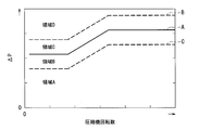
- the figure which shows the judgment value in closing control of the electronic expansion valve based on the pressure difference of the refrigerating-cycle apparatus which concerns on this embodiment.
- FIGS. 1 and 2 An embodiment of a refrigeration cycle apparatus according to the present invention will be described with reference to FIGS. 1 and 2.
- the same or corresponding components are denoted by the same reference numerals.
- FIG. 1 is a block diagram of a refrigeration cycle apparatus according to an embodiment of the present invention.
- the refrigeration cycle apparatus 1 is, for example, a so-called chiller.
- the refrigeration cycle apparatus 1 performs heat exchange between a refrigerant circulating in the refrigeration cycle apparatus 1 and air, a first heat exchanger 5 as an air heat exchanger, a refrigerant circulating in the refrigeration cycle apparatus 1 and a use side
- a second heat exchanger 6 as a water heat exchanger is provided, which performs heat exchange with water and brine flowing through 100.
- the refrigeration cycle apparatus 1 may be an air conditioner.
- the refrigeration cycle apparatus 1 includes a compressor 7, a first heat exchanger 5, an electronic expansion valve 8, a second heat exchanger 6, a first heat exchanger 5, a second heat exchanger 6, and a compressor 7. And a refrigerant pipe 9 which connects the electronic expansion valve 8 to circulate the refrigerant.
- the refrigeration cycle apparatus 1 sends the refrigerant discharged from the compressor 7 to one of the first heat exchanger 5 and the second heat exchanger 6, and the refrigerant cycle device 1 of the first heat exchanger 5 and the second heat exchanger 6 A four-way valve 11 which sucks the refrigerant that has passed the other side into the compressor 7 again, an accumulator 12 provided in a refrigerant pipe 9 between the four-way valve 11 and the compressor 7, an electronic expansion valve 8 and a second heat exchanger 6 And a silencer 13 provided in the refrigerant pipe 9 between them.
- the first heat exchanger 5 and the second heat exchanger 6 are, for example, a fin and tube type.
- the first heat exchanger 5 functions as a condenser when performing a cooling operation of the refrigeration cycle device 1 and functions as an evaporator when performing a heating operation of the refrigeration cycle device 1.
- the second heat exchanger 6 functions as an evaporator when performing a cooling operation of the refrigeration cycle device 1 and functions as a condenser when performing a heating operation of the refrigeration cycle device 1.
- the refrigeration cycle apparatus 1 in the cooling operation cools the fluid such as water or brine flowing in the use side 100 with the second heat exchanger 6, and the refrigeration cycle apparatus 1 in the heating operation flows the use side 100 in the circulation mode.
- the fluid such as water or brine is heated by the second heat exchanger 6.
- the fluid flowing through the use side 100 may be various liquids such as a cleaning liquid or oil other than the fluid such as water or brine, or may be other fluids.
- the compressor 7 compresses, pressurizes and discharges the refrigerant.
- the compressor 7 may be capable of changing the operating frequency by, for example, known inverter control, or may not be capable of changing the operating frequency.
- the electronic expansion valve 8 is, for example, a PMV (Pulse Motor Valve).
- the electronic expansion valve 8 can adjust the opening degree of the valve.
- the electronic expansion valve 8 includes, for example, a valve body having a through hole, a needle that can move back and forth with respect to the through hole, and a power source that moves the needle back and forth.
- the electronic expansion valve 8 when the needle is most separated from the through hole, the refrigerant of the refrigerant pipe 9 is the easiest to flow. At this time, the electronic expansion valve 8 is in an open state, and the opening degree of the electronic expansion valve 8 is the largest.
- the power source is, for example, a stepping motor.
- the electronic expansion valve 8 When the number of pulses input to the stepping motor is zero, the electronic expansion valve 8 is closed. When the number of pulses input to the stepping motor is the maximum pulse, the electronic expansion valve 8 is completely opened.
- the maximum number of pulses is, for example, several hundred pulses. In the present embodiment, the maximum pulse number is 500 pulses.
- the refrigerant pipe 9 sequentially connects the compressor 7, the four-way valve 11, the first heat exchanger 5, the electronic expansion valve 8, and the second heat exchanger 6.
- the refrigerant pipe 9 is a first refrigerant pipe 9a connecting the discharge side of the compressor 7 to the four-way valve 11, a second refrigerant pipe 9b connecting the suction side of the compressor 7 to the four-way valve 11, a four-way valve 11
- a third refrigerant pipe 9c connecting the first heat exchanger 5, a fourth refrigerant pipe 9d connecting the first heat exchanger 5 and the second heat exchanger 6, a second heat exchanger 6 and a four-way valve 11
- a fifth refrigerant pipe 9e to be connected.
- the electronic expansion valve 8 and the silencer 13 are provided in the middle of the fourth refrigerant pipe 9d.
- the four-way valve 11 switches the direction of the refrigerant flowing through the refrigerant pipe 9.
- heating operation flow of the refrigerant shown by a solid line in FIG. 1
- the four-way valve 11 transfers the refrigerant from the first refrigerant pipe 9a to the fifth refrigerant pipe 9e
- the refrigerant is circulated and the refrigerant is circulated from the third refrigerant pipe 9c to the second refrigerant pipe 9b.
- the refrigeration cycle device 1 is cooled (flow of refrigerant indicated by broken line in FIG.
- the four-way valve 11 transfers the refrigerant from the first refrigerant pipe 9a to the third refrigerant pipe 9c.
- the refrigerant is circulated and the refrigerant is circulated from the fifth refrigerant pipe 9e to the second refrigerant pipe 9b.
- the refrigeration cycle apparatus 1 further includes a control unit 15 electrically connected to the electronic expansion valve 8 and the four-way valve 11 via a signal line (not shown).
- the control unit 15 may be connected to the compressor 7 capable of changing the operating frequency.
- the control unit 15 includes a central processing unit (not shown), and a storage unit (not shown) for storing various calculation programs executed by the central processing unit, parameters, and the like.
- the control unit 15 reads various control programs from the auxiliary storage device to the main storage device, and causes the central processing unit to execute the various control programs read to the main storage device.
- the control unit 15 switches the state of the four-way valve 11 based on the request of the use side 100 to switch the cooling operation and the heating operation of the refrigeration cycle apparatus 1.
- the refrigeration cycle apparatus 1 discharges the compressed high-temperature and high-pressure refrigerant from the compressor 7, and the refrigerant is subjected to the first heat via the four-way valve 11. Send to the switch 5.
- the first heat exchanger 5 exchanges heat between the air and the refrigerant passing through the inside of the tube to cool the refrigerant to a high pressure liquid state. That is, during the cooling operation, the first heat exchanger 5 functions as a condenser.
- the refrigerant that has passed through the first heat exchanger 5 passes through the electronic expansion valve 8 and is decompressed to become a low pressure gas-liquid two-phase refrigerant, and reaches the second heat exchanger 6.
- the second heat exchanger 6 exchanges heat between the water on the use side 100 and the refrigerant passing through the inside of the tube to cool the water. At this time, the second heat exchanger 6 functions as an evaporator that evaporates the refrigerant into a gas state. The refrigerant that has passed through the second heat exchanger 6 is sucked back into the compressor 7.
- the refrigeration cycle apparatus 1 reverses the four-way valve 11 to generate refrigerant flow in the refrigeration cycle in the opposite direction to the refrigerant flow at the time of cooling.
- the second heat exchanger 6 functions as a condenser
- the first heat exchanger 5 functions as an evaporator.
- the refrigeration cycle apparatus 1 may not be provided with the four-way valve 11 and may be dedicated to cooling.
- the discharge side of the compressor 7 is connected to the first heat exchanger 5 through the refrigerant pipe 9, and the suction side of the compressor 7 is connected to the second heat exchanger 6 through the refrigerant pipe 9.
- the refrigeration cycle apparatus 1 is provided in a first temperature detector 21 for detecting the temperature of the refrigerant at the inlet of the evaporator, and in the refrigerant pipe 9 between the evaporator and the compressor 7 to measure the temperature on the suction side of the compressor 7 And a second temperature sensor 22 for detecting.
- the first temperature detector 21 and the second temperature detector 22 are connected to the control unit 15 via a signal line (not shown).
- the detection results of the first temperature detector 21 and the second temperature detector 22 are transmitted to the control unit 15 via a signal line.
- the first temperature detector 21 is an evaporator in the cooling operation, that is, a first temperature detector 23a for cooling operation that detects the temperature of the refrigerant at the inlet of the second heat exchanger 6, and an evaporator in the heating operation, that is, the first And a first temperature detector 23 b for heating operation that detects the temperature of the refrigerant at the inlet of the heat exchanger 5.
- the second temperature detector 22 is provided in the second refrigerant pipe 9b.
- the second temperature detector 22 detects the temperature of the refrigerant on the outlet side of the evaporator. That is, the second temperature detector 22 detects the temperature of the refrigerant returning from the second heat exchanger 6 to the compressor 7 in the cooling operation, and the temperature of the refrigerant returning from the first heat exchanger 5 to the compressor 7 in the heating operation To detect
- the control unit 15 sets the opening degree of the electronic expansion valve 8 so that the difference between the temperature detected by the first temperature detector 21 and the temperature detected by the second temperature detector 22, that is, the temperature difference, falls within a predetermined temperature difference setting range. adjust.
- This control is called “opening / closing control of the electronic expansion valve 8 based on a temperature difference".
- the temperature difference setting range is related to the outside air temperature to which the first heat exchanger 5 is exposed, the water temperature required from the user side 100, that is, the setting temperature of the refrigeration cycle apparatus 1, and the rotation speed of the compressor 7.
- the refrigeration cycle apparatus 1 is provided in the first refrigerant pipe 9a to detect the discharge pressure of the compressor 7, and the second refrigerant pipe 9b is provided for detecting the suction pressure of the compressor 7.
- a low pressure detector 26 is provided.
- the high pressure detector 25 and the low pressure detector 26 are connected to the control unit 15 via a signal line (not shown).
- the detection results of the high pressure detector 25 and the low pressure detector 26 are transmitted to the control unit 15 via a signal line.
- the high pressure detector 25 is provided in the refrigerant pipe 9 between the compressor 7 and the condenser (the first heat exchanger 5 in the cooling operation, and the second heat exchanger 6 in the heating operation).
- the low pressure detector 26 is provided in the refrigerant pipe 9 between the evaporator (the second heat exchanger 6 in the cooling operation and the first heat exchanger 5 in the heating operation) and the compressor 7.
- the low pressure detector 26 is provided in a refrigerant pipe 9 connecting the accumulator 12 and the compressor 7.
- the refrigerating cycle apparatus 1 has a transition period of start of the refrigerating cycle apparatus 1 or a severe use environment such as a situation where the difference between the required water temperature of the use side 100 and the outside air temperature is extremely large. 1 temporarily deviates from the use range, or the difference between the discharge pressure and the suction pressure of the compressor 7 due to the rapid change of the rotational speed of the compressor 7, that is, the pressure difference deviates from the use range of the compressor 7 You
- control unit 15 of the refrigeration cycle apparatus 1 controls the opening and closing of the electronic expansion valve 8 based on the difference between the pressures detected by the high pressure detector 25 and the low pressure detector 26. This control is called “close control of the electronic expansion valve 8 based on a pressure difference”.
- FIG. 2 is a diagram showing determination values in closing control of the electronic expansion valve based on the pressure difference of the refrigeration cycle device according to the present embodiment.
- the control unit 15 of the refrigeration cycle apparatus 1 is the difference in the detected pressure between the high pressure detector 25 and the low pressure detector 26, that is, the pressure difference ⁇ P
- the opening and closing of the electronic expansion valve 8 are controlled based on the relationship with the rotational speed.
- the solid line A in FIG. 2 is a reference value. If the pressure difference ⁇ P is equal to or greater than the reference value, the compressor 7 can be operated in an appropriate use range. In other words, the reference value A is set so as to be able to operate the compressor 7 in an appropriate use range.
- the broken line B in FIG. 2 is, for example, 20% to 30% higher, preferably 25% higher than the reference value.
- This broken line B is called a reference value + ⁇ .
- the dashed line C in FIG. 2 is, for example, 20 to 30 percent lower, preferably 25 percent lower than the reference value.
- This broken line C is called a reference value - ⁇ .
- the ⁇ value and the ⁇ value may be the same or different.
- the ⁇ value and the ⁇ value are set in consideration of the use range of the compressor 7, the system conditions required for the refrigeration cycle apparatus 1, the margin, and the like.
- a range in which the pressure difference ⁇ P is equal to or less than a reference value ⁇ (broken line C) is referred to as a region A.
- a range in which the pressure difference ⁇ P is larger than the reference value ⁇ (broken line C) and not more than the reference value (solid line A) is referred to as a region B.
- a range in which the pressure difference ⁇ P is larger than the reference value (solid line A) and not more than the reference value + ⁇ (broken line B) is referred to as a region C.
- a range in which the pressure difference ⁇ P is higher than the reference value + ⁇ (broken line B) is referred to as a region D.
- the opening degree of the electronic expansion valve 8 is adjusted by opening or closing the electronic expansion valve 8 based on the difference between the detected temperatures of the second temperature sensor 22 and the first temperature sensor 21.
- control unit 15 determines that the difference between the detected pressures of the high pressure detector 25 and the low pressure detector 26 is less than or equal to a predetermined threshold (reference value + ⁇ , broken line B) (that is, region A, region B, or In the case of region C), the electronic expansion valve 8 is inhibited from being opened, and the electronic expansion valve 8 is closed based on the difference in detected temperature between the second temperature sensor 22 and the first temperature sensor 21. Adjust the opening degree of the valve 8.
- a predetermined threshold reference value + ⁇ , broken line B
- the control unit 15 controls the opening and closing of the electronic expansion valve 8 based on the temperature difference between the second temperature detector 22 and the first temperature detector 21 (so-called normal Control). Further, when the pressure difference ⁇ P is in the region C, the region B, and the region A, the control unit 15 suppresses the opening / closing control of the electronic expansion valve 8 based on the temperature difference of the electronic expansion valve 8 to thereby control the electronic expansion valve 8.
- the control for closing the electronic expansion valve 8 is executed, that is, the closing control of the electronic expansion valve 8 based on the pressure difference.
- the refrigeration cycle apparatus 1 performs electronic expansion so that the temperature difference between the first temperature detector 21 and the second temperature detector 22 falls within a predetermined temperature difference setting range when the pressure difference ⁇ P is in the region D. Adjust the opening degree of the valve 8. In other words, when the pressure difference ⁇ P is in the region D, the refrigeration cycle apparatus 1 sets the temperature so that the temperature difference between the first temperature detector 21 and the second temperature detector 22 falls within the predetermined temperature difference setting range. The opening and closing control of the electronic expansion valve 8 is executed based on the difference.
- the refrigeration cycle apparatus 1 prohibits the electronic expansion valve 8 from being opened when the pressure difference ⁇ P is in the area C, the area B, and the area A, while controlling to close the electronic expansion valve 8, ie, the pressure difference.
- the closing control of the electronic expansion valve 8 is executed.
- the refrigeration cycle apparatus 1 inhibits the increase of the flow rate of the refrigerant in a situation (other than the area D) where the large pressure difference ⁇ P is not required, while reducing the flow rate of the refrigerant.
- the refrigeration cycle apparatus 1 suppresses the increase in the refrigerant sucked into the compressor 7, and the compressor 7 deviates from the use range. Avoid driving. That is, the control unit 15 prohibits control on the side where the opening degree of the electronic expansion valve 8 is opened in the open / close control based on the temperature difference.
- the controller 15 decreases the pressure difference ⁇ P, and the electronic expansion valve It is judged at a shorter time interval whether it is necessary to adjust the opening degree of (8).
- the control unit 15 determines whether the pressure difference ⁇ P requires the adjustment of the opening of the electronic expansion valve 8 as the pressure difference ⁇ P is smaller in the region C, the region B, and the region A. Do at intervals.
- the control unit 15 determines whether the opening degree of the electronic expansion valve 8 needs to be adjusted at the shortest time interval, for example, 10 seconds.
- the control unit 15 determines whether it is necessary to adjust the opening of the electronic expansion valve 8 at time intervals longer than the determination in the region A, for example, 20 seconds. Do.
- the control part 15 determines whether adjustment of the opening degree of the electronic expansion valve 8 is required by the time interval in the opening / closing control based on a normal temperature difference. There is. This time interval is set to a time interval longer than the judgment in the area B, for example, an interval of 30 seconds.
- the refrigeration cycle device 1 quickly reduces the use range of the compressor 7 to the normal range, so that the pressure difference ⁇ P is in the area further away from the area D, the opening degree of the electronic expansion valve 8 at shorter time intervals. It is determined whether it is necessary to adjust the value of (1), and the degree of opening of the electronic expansion valve 8 is actually adjusted (controlled only in the closing direction).
- the control unit 15 reduces the opening of the electronic expansion valve 8 by 30 pulses, and when the pressure difference ⁇ P is still in the region A after 10 seconds, for example, The opening degree of the electronic expansion valve 8 is reduced by 30 pulses. The control unit 15 repeats this until the pressure difference ⁇ P leaves the region A. Further, when the pressure difference ⁇ P is in the region B, for example, the control unit 15 throttles the opening degree of the electronic expansion valve 8 by 30 pulses, and in the case where the pressure difference ⁇ P is still in the region B after 20 seconds, Again, the opening degree of the electronic expansion valve 8 is reduced by 30 pulses. The control unit 15 repeats this until the pressure difference ⁇ P leaves the region B. In other words, the control unit 15 gradually throttles the electronic expansion valve 8 until the pressure difference ⁇ P reaches the reference value or more, ie, the region C and the region D.
- the change amount of the opening degree of the electronic expansion valve 8 at each time may not be constant (every 30 pulses in the example).
- the throttling amount of each electronic expansion valve 8 may be different depending on the opening degree before the throttling operation. For example, the throttling amount of each electronic expansion valve 8 is set larger as the opening degree before the throttling operation is larger.
- the aperture amount of the electronic expansion valve 8 is set to 30 pulses if the opening degree before the aperture operation exceeds 100 pulses, and is set to 15 pulses if the opening degree before the aperture operation is 100 pulses or less .
- the change amount of the opening degree of the electronic expansion valve 8, that is, the throttling amount of the electronic expansion valve 8 may be different for each region.
- the throttling amount of the electronic expansion valve 8 is set larger as the pressure difference ⁇ P is smaller.
- the throttling amount of the electronic expansion valve 8 in the region A is set to 45 pulses
- the throttling amount of the electronic expansion valve 8 in the region B is set to 30 pulses.
- the controller 15 reduces the difference between the detected pressures. Close the opening of expansion valve 8 more
- the pressure difference ⁇ P (the detected pressure of the high pressure detector 25)-(the detected pressure of the low pressure detector 26) is a negative value Is evaluated by its absolute value. If (the pressure detected by the high pressure detector 25) ⁇ (the pressure detected by the low pressure detector 26) is a negative value, at least one of the high pressure detector 25 and the low pressure detector 26 is broken, There is a possibility that the signal line which transmits a detection result to control part 15 from them may be disconnected. In such a case, if the pressure difference ⁇ P is erroneously detected and the electronic expansion valve 8 is throttled too much, there is a possibility that it deviates from the use range of the compressor 7. Therefore, when (the detection pressure of the high pressure detector 25)-(the detection pressure of the low pressure detector 26) is a negative value, the control unit 15 evaluates the pressure difference ⁇ P with an absolute value, and the electronic expansion valve 8 Avoid over-squeezing.
- the usage range of the outside air temperature is wide (for example, minus several tens of degrees to plus plus tens of degrees) in the refrigeration cycle apparatus or in the refrigeration cycle apparatus where the set temperature range of the user side 100 is wide, applying the conventional super heat control
- the pressure difference between the discharge pressure and the suction pressure of the compressor becomes smaller, which may cause the compressor to deviate from the proper use range.
- the refrigeration cycle apparatus 1 is configured such that the second detected pressure difference between the high pressure detector 25 and the low pressure detector 26 is greater than a predetermined threshold (reference value + ⁇ ).
- the opening degree of the electronic expansion valve 8 is adjusted by opening or closing the electronic expansion valve 8 based on the difference between the detected temperatures of the temperature sensor 22 and the first temperature sensor 21, and the high pressure sensor 25 and the low pressure
- a predetermined threshold reference value + ⁇
- the electronic expansion valve 8 is prohibited from being opened, and the second temperature detector 22 and the first temperature detector 21
- the degree of opening of the electronic expansion valve 8 is adjusted by closing the electronic expansion valve 8 based on the difference in the detected temperature.
- the refrigeration cycle apparatus 1 has a wide range of use of the outside air temperature or a wide range of the set temperature range on the use side 100, when the transition period of the start or the rapid change of the rotational speed of the compressor 7 A pressure difference between the discharge side and the suction side necessary to operate the compressor 7 in an appropriate use range can be secured.
- the high pressure detector 25 detects the difference between the detected pressures of the high pressure detector 25 and the low pressure detector 26 at or below a predetermined threshold (reference value + ⁇ ). It is judged in a shorter time whether it is necessary to adjust the opening degree of the electronic expansion valve 8 as the difference between the detected pressure of the low pressure sensor 26 and the low pressure pressure detector 26 is smaller. Therefore, the refrigeration cycle apparatus 1 opens the electronic expansion valve 8 at a shorter time interval as the pressure difference ⁇ P is in a region farther from the region D (that is, in the region B than the region C and the region A than the region B). It is possible to determine whether it is necessary to adjust the degree and adjust the opening degree of the electronic expansion valve 8 (control only in the closing direction) to quickly put the use range of the compressor 7 within the normal range. .
- a predetermined threshold reference value + ⁇
- the refrigeration cycle device 1 when the difference in detected pressure between the high pressure detector 25 and the low pressure detector 26 is equal to or less than a predetermined threshold (reference value + ⁇ ), the high pressure detector 25 The smaller the difference in detected pressure between the low pressure sensor 26 and the low pressure pressure detector 26, the larger the degree of opening of the electronic expansion valve 8 is. Therefore, the refrigeration cycle device 1 reduces the flow rate of the refrigerant to a larger extent as the pressure difference ⁇ P is in a region farther from the region D (that is, in the region B than the region C and the region A than the region B). The range of use of can be quickly brought into the normal range.
- the refrigeration cycle apparatus 1 when (the pressure detected by the high pressure detector 25)-(the pressure detected by the low pressure detector 26) is a negative value, the high pressure detector 25 and the low pressure are detected. The difference between the pressure detected by the pressure sensor 26 and the pressure is evaluated by the absolute value. Therefore, in the refrigeration cycle apparatus 1, at least one of the high pressure detector 25 and the low pressure detector 26 is broken by any chance, or the signal line for transmitting the detection result to the control unit 15 is broken. However, the electronic expansion valve 8 is prevented from being throttled too much, and the range of use of the compressor 7 is not deviated.
- the pressure difference between the discharge pressure and the suction pressure of the compressor 7 is likely to deviate quickly from the use range of the compressor 7 and in the deviated situation. It can control to the use range.
Landscapes
- Engineering & Computer Science (AREA)
- Physics & Mathematics (AREA)
- Mechanical Engineering (AREA)
- Thermal Sciences (AREA)
- General Engineering & Computer Science (AREA)
- Air Conditioning Control Device (AREA)
Abstract
冷凍サイクル装置(1)は、圧縮機(7)の吐出圧力を検知する高圧圧力検知器(25)と、圧縮機(7)の吸込圧力を検知する低圧圧力検知器(26)と、蒸発器の入口の冷媒の温度を検知する第一温度検知器(21)と、圧縮機(7)の吸込み側の温度を検知する第二温度検知器(22)と、高圧圧力検知器(25)と低圧圧力検知器(26)との検知圧力の差異が予め定める所定の閾値よりも大きい場合には、第二温度検知器(22)と第一温度検知器(21)との検知温度の差異に基づいて電子膨張弁(8)を開く、または閉じることによって電子膨張弁(8)の開度を調整し、検知圧力の差異が閾値以下の場合には、電子膨張弁(8)を開くことを禁じ、第二温度検知器(22)と第一温度検知器(21)との検知温度の差異に基づいて電子膨張弁8を閉じることによって電子膨張弁(8)の開度を調整する制御部(15)と、を備えている。
Description
本発明に係る実施形態は、冷凍サイクル装置に関する。
油分離器からアキュムレータに冷凍機油を流すバイパス回路に設けられる油循環量調整用膨張弁を備える冷凍サイクル装置が知られている。この従来の冷凍サイクル装置は、圧縮機の吐出側に設けられる吐出圧力検出手段と、吸入側に設けられる吸入圧力検出手段と、を備えている。従来の冷凍サイクル装置は、それぞれの圧力検出手段の信号を基に圧縮機の吐出側と吸入側との圧力差を演算し、この演算結果を基に油循環量調整用膨張弁の開度を制御する。
従来の冷凍サイクル装置は、吐出側と吸入側との圧力差に応じて油循環量調整用膨張弁の開度を調整し、(バイパス回路を流れる冷凍機油の循環量)>(アキュムレータから圧縮機に戻る油単体の循環量)をぎりぎり満足する状態を常に保ち、冷凍サイクルの能力を低下させることなく冷凍サイクルの効率を常に最大にする。
ところで、所謂チラー(chiller)のような冷凍サイクル装置がある。この種の冷凍サイクル装置では、その始動の過渡期や、例えば、利用側の要求水温と外気温との差が極めて大きい状況のような使用環境の過酷さによって、冷凍サイクル装置が使用範囲を一時的に逸脱したり、圧縮機の回転数の急激な変更にともなう圧縮機の吐出圧力と吸込圧力との差、つまり圧力差が圧縮機の使用範囲を逸脱したりする。このような圧縮機の使用範囲の逸脱は、圧縮機の寿命を著しく短縮したり、圧縮機の損傷を誘引したりするので好ましくない。
そこで、本発明は、圧縮機の吐出圧力と吸込圧力との圧力差が圧縮機の使用範囲から逸脱しそうな状況、および逸脱した状況において速やかに適正な使用範囲へ制御可能な冷凍サイクル装置を提案する。
前記の課題を解決するため本発明の実施形態に係る冷凍サイクル装置は、圧縮機と、凝縮器と、電子膨張弁と、蒸発器と、前記圧縮機、前記凝縮器、前記電子膨張弁、および前記蒸発器を接続して冷媒を流通させる冷媒配管と、前記圧縮機と前記凝縮器との間の前記冷媒配管に設けられて前記圧縮機の吐出圧力を検知する高圧圧力検知器と、前記蒸発器と前記圧縮機との間の前記冷媒配管に設けられて前記圧縮機の吸込圧力を検知する低圧圧力検知器と、前記蒸発器の入口の前記冷媒の温度を検知する第一温度検知器と、前記蒸発器から前記圧縮機の間の前記冷媒配管に設けられて前記圧縮機の吸込み側の温度を検知する第二温度検知器と、前記高圧圧力検知器と前記低圧圧力検知器との検知圧力の差異が予め定める所定の閾値よりも大きい場合には、前記第二温度検知器と前記第一温度検知器との検知温度の差異に基づいて前記電子膨張弁を開く、または閉じることによって前記電子膨張弁の開度を調整し、前記検知圧力の差異が前記閾値以下の場合には、前記電子膨張弁を開くことを禁じ、前記第二温度検知器と前記第一温度検知器との検知温度の差異に基づいて前記電子膨張弁を閉じることによって前記電子膨張弁の開度を調整する制御部と、を備えている。
本発明の実施形態に係る冷凍サイクル装置の前記制御部は、前記検知圧力の差異が前記閾値以下の場合には、前記検知圧力の差異が小さいほど前記電子膨張弁の開度の調整を要するか否かの判定をより短い時間間隔で行うことが好ましい。
また、本発明の実施形態に係る冷凍サイクル装置の前記制御部は、前記検知圧力の差異が前記閾値以下の場合には、前記検知圧力の差異が小さいほど前記電子膨張弁の開度をより大きく閉じることが好ましい。
本発明の実施形態に係る冷凍サイクル装置の前記検知圧力の差異は、(前記高圧圧力検知器の検知圧力)-(前記低圧圧力検知器の検知圧力)が負値の場合には、前記高圧圧力検知器の検知圧力と前記低圧圧力検知器の検知圧力との差の絶対値であることが好ましい。
本発明に係る冷凍サイクル装置の実施形態について、図1から図2を参照して説明する。なお、複数の図面中、同一または相当する構成には同一の符号を付している。
図1は、本発明の実施形態に係る冷凍サイクル装置のブロック図である。
図1に示すように、本実施形態に係る冷凍サイクル装置1は、例えば所謂チラー(chiller)である。冷凍サイクル装置1は、冷凍サイクル装置1を循環する冷媒と空気との間で熱交換を行う、空気熱交換器としての第一熱交換器5と、冷凍サイクル装置1を循環する冷媒と利用側100を流通する水やブライン(brine)との間で熱交換を行う、水熱交換器としての第二熱交換器6と、を備えている。なお、冷凍サイクル装置1は、空気調和機であっても良い。
冷凍サイクル装置1は、圧縮機7と、第一熱交換器5と、電子膨張弁8と、第二熱交換器6と、第一熱交換器5、第二熱交換器6、圧縮機7、および電子膨張弁8を接続して冷媒を流通させる冷媒配管9と、を備えている。
また、冷凍サイクル装置1は、圧縮機7から吐出される冷媒を第一熱交換器5および第二熱交換器6の一方へ送り、かつ第一熱交換器5および第二熱交換器6の他方を通過した冷媒を再び圧縮機7へ吸い込ませる四方弁11と、四方弁11と圧縮機7との間の冷媒配管9に設けられるアキュムレータ12と、電子膨張弁8と第二熱交換器6との間の冷媒配管9に設けられる消音器13と、を備えている。
第一熱交換器5および第二熱交換器6は、例えばフィンアンドチューブ型である。第一熱交換器5は、冷凍サイクル装置1を冷却運転する際、凝縮器として機能し、冷凍サイクル装置1を加熱運転する際、蒸発器として機能する。第二熱交換器6は、冷凍サイクル装置1を冷却運転する際、蒸発器として機能し、冷凍サイクル装置1を加熱運転する際、凝縮器として機能する。なお、冷却運転中の冷凍サイクル装置1は、利用側100を流通する水やブライン等の流体を第二熱交換器6で冷却し、加熱運転中の冷凍サイクル装置1は、利用側100を流通する水やブライン等の流体を第二熱交換器6で加熱する。ここで、利用側100を流通する流体は、水やブライン等の流体の他にも洗浄液や油等の種々の液体であってもよく、その他の流体であってもよい。
圧縮機7は、冷媒を圧縮し、昇圧して吐出する。圧縮機7は、例えば公知のインバータ制御によって運転周波数を変更可能なものであっても良いし、運転周波数を変更できないものであっても良い。
電子膨張弁8は、例えばPMV(Pulse Motor Valve)である。電子膨張弁8は、弁の開度を調節できる。図示は省略するが、電子膨張弁8は、例えば、貫通孔を有する弁本体と、貫通孔に対して進退可能なニードルと、ニードルを進退させる動力源と、を備えている。電子膨張弁8は、貫通孔をニードルで塞いだとき、冷媒配管9の冷媒の流通を止める(遮断する)。このとき、電子膨張弁8は閉じた状態になり、電子膨張弁8の開度は最も小さい。一方、電子膨張弁8は、ニードルが貫通孔から最も離れたとき、冷媒配管9の冷媒が最も流れやすい。このとき、電子膨張弁8は開いた状態になり、電子膨張弁8の開度は最も大きい。
動力源は、例えば、ステッピングモータである。ステッピングモータに入力されるパルス数が0パルスのとき、電子膨張弁8は閉じた状態になる。ステッピングモータに入力されるパルス数が最大パルスのとき、電子膨張弁8は完全に開いた状態になる。最大パルス数は、例えば数百パルスである。本実施形態では、最大パルス数を500パルスとする。
冷媒配管9は、圧縮機7、四方弁11、第一熱交換器5、電子膨張弁8、および第二熱交換器6を順次に接続している。冷媒配管9は、圧縮機7の吐出側と四方弁11とを繋ぐ第一冷媒配管9aと、圧縮機7の吸込側と四方弁11とを繋ぐ第二冷媒配管9bと、四方弁11と第一熱交換器5とを繋ぐ第三冷媒配管9cと、第一熱交換器5と第二熱交換器6とを繋ぐ第四冷媒配管9dと、第二熱交換器6と四方弁11とを繋ぐ第五冷媒配管9eと、を含んでいる。電子膨張弁8および消音器13は、第四冷媒配管9dの途中に設けられている。
四方弁11は、冷媒配管9を流れる冷媒の向きを切替える。冷凍サイクル装置1を加熱運転(図1中、実線で示す冷媒の流れ)して利用側100の水温を上昇させるとき、四方弁11は、第一冷媒配管9aから第五冷媒配管9eへ冷媒を流通させ、かつ第三冷媒配管9cから第二冷媒配管9bへ冷媒を流通させる。冷凍サイクル装置1を冷却運転(図1中、破線で示す冷媒の流れ)して利用側100の水温を下降させるとき、四方弁11は、第一冷媒配管9aから第三冷媒配管9cへ冷媒を流通させ、かつ第五冷媒配管9eから第二冷媒配管9bへ冷媒を流通させる。
また、冷凍サイクル装置1は、電子膨張弁8、四方弁11に信号線(図示省略)を介して電気的に接続される制御部15を備えている。制御部15は、運転周波数を変更可能な圧縮機7に接続されていても良い。
制御部15は、中央演算処理装置(図示省略)と、中央演算処理装置が実行する各種演算プログラム、パラメータなどを記憶する記憶装置(図示省略)と、を備えている。制御部15は、各種制御プログラムを補助記憶装置から主記憶装置へ読み込み、主記憶装置に読み込まれた各種制御プログラムを中央演算処理装置で実行する。
制御部15は、利用側100の要求に基づいて四方弁11の状態を切り替えて、冷凍サイクル装置1の冷却運転と加熱運転とを切り替える。
冷却運転の際(図1中、破線で示す冷媒の流れ)、冷凍サイクル装置1は、圧縮された高温高圧の冷媒を圧縮機7から吐出し、四方弁11を介してこの冷媒を第一熱交換器5へ送る。第一熱交換器5は、空気とチューブ内を通る冷媒との間で熱交換を行い、冷媒を冷却して高圧の液状態にする。つまり、冷却運転時、第一熱交換器5は、凝縮器として機能する。第一熱交換器5を通過した冷媒は、電子膨張弁8を通過して減圧され低圧の気液二相冷媒になって第二熱交換器6に到達する。第二熱交換器6は、利用側100の水とチューブ内を通る冷媒との間で熱交換を行い、水を冷却する。このとき、第二熱交換器6は、冷媒を蒸発させて気体状態にする蒸発器として機能する。第二熱交換器6を通過した冷媒は、圧縮機7へ吸い込まれて戻る。
他方、加熱運転の際(図1中、実線で示す冷媒の流れ)、冷凍サイクル装置1は、四方弁11を反転させて冷凍サイクルに冷却時の冷媒の流れと逆向きの冷媒の流れを生じさせ、第二熱交換器6を凝縮器として機能させ、第一熱交換器5を蒸発器として機能させる。
なお、冷凍サイクル装置1は、四方弁11を備えない、冷却専用のものであってもよい。この場合、圧縮機7の吐出側は冷媒配管9を通じて第一熱交換器5に接続され、圧縮機7の吸込側は冷媒配管9を通じて第二熱交換器6に接続される。
冷凍サイクル装置1は、蒸発器の入口の冷媒の温度を検知する第一温度検知器21と、蒸発器から圧縮機7の間の冷媒配管9に設けられて圧縮機7の吸込み側の温度を検知する第二温度検知器22と、を備えている。第一温度検知器21および第二温度検知器22は、信号線(図示省略)を介して制御部15に接続されている。第一温度検知器21および第二温度検知器22の検知結果は、信号線を介して制御部15に送信される。
第一温度検知器21は、冷却運転における蒸発器、つまり第二熱交換器6の入口の冷媒の温度を検知する冷却運転用第一温度検知器23aと、加熱運転における蒸発器、つまり第一熱交換器5の入口の冷媒の温度を検知する加熱運転用第一温度検知器23bと、を含んでいる。
第二温度検知器22は、第二冷媒配管9bに設けられている。第二温度検知器22は、蒸発器の出口側の冷媒の温度を検知している。つまり、第二温度検知器22は、冷却運転において第二熱交換器6から圧縮機7へ戻る冷媒の温度を検知し、加熱運転において第一熱交換器5から圧縮機7へ戻る冷媒の温度を検知する。
制御部15は、第一温度検知器21の検知温度と第二温度検知器22の検知温度との差異、つまり温度差が予め定める温度差設定範囲に収まるよう、電子膨張弁8の開度を調整する。この制御を「温度差に基づく電子膨張弁8の開閉制御」と呼ぶ。温度差設定範囲は、第一熱交換器5が晒される外気温、利用側100から要求される水温、つまり冷凍サイクル装置1の設定温度、および圧縮機7の回転数に関係づけられている。
また、冷凍サイクル装置1は、第一冷媒配管9aに設けられて圧縮機7の吐出圧力を検知する高圧圧力検知器25と、第二冷媒配管9bに設けられて圧縮機7の吸込圧力を検知する低圧圧力検知器26と、を備えている。高圧圧力検知器25および低圧圧力検知器26は、信号線(図示省略)を介して制御部15に接続されている。高圧圧力検知器25および低圧圧力検知器26の検知結果は、信号線を介して制御部15に送信される。
高圧圧力検知器25は、圧縮機7と凝縮器(冷却運転における第一熱交換器5であり、加熱運転における第二熱交換器6)との間の冷媒配管9に設けられている。
低圧圧力検知器26は、蒸発器(冷却運転における第二熱交換器6であり、加熱運転における第一熱交換器5)と圧縮機7との間の冷媒配管9に設けられている。低圧圧力検知器26は、アキュムレータ12と圧縮機7とを繋ぐ冷媒配管9に設けられている。
ところで、冷凍サイクル装置1の始動の過渡期や、例えば、利用側100の要求水温と外気温との差が極めて大きい状況のような使用環境の過酷さによって、冷凍サイクル装置1では、冷凍サイクル装置1が使用範囲を一時的に逸脱したり、圧縮機7の回転数の急激な変更にともなう圧縮機7の吐出圧力と吸込圧力との差、つまり圧力差が圧縮機7の使用範囲から逸脱したりしてしまう。
そこで、冷凍サイクル装置1の制御部15は、高圧圧力検知器25と低圧圧力検知器26との検知圧力の差異に基づいて電子膨張弁8の開閉を制御する。この制御を「圧力差に基づく電子膨張弁8の閉制御」と呼ぶ。
図2は、本実施形態に係る冷凍サイクル装置の圧力差に基づく電子膨張弁の閉制御における判定値を示す図である。
図2に示すように、本実施形態に係る冷凍サイクル装置1の制御部15は、高圧圧力検知器25と低圧圧力検知器26との検知圧力の差異、つまり圧力差ΔPと、圧縮機7の回転数との関係に基づいて、電子膨張弁8の開閉を制御する。
図2の実線Aは、基準値である。圧力差ΔPが基準値以上であれば、圧縮機7は、適正な使用範囲で運転することが可能である。換言すると、基準値Aは、圧縮機7を適正な使用範囲で運転することが可能なように設定されている。
図2の破線Bは、基準値に対して例えば20パーセントから30パーセント高く、好ましくは25パーセント高い。この破線Bを基準値+αと呼ぶ。図2の破線Cは、基準値に対して例えば20パーセントから30パーセント低く、好ましくは25パーセント低い。この破線Cを基準値-βと呼ぶ。α値とβ値とは同じであっても良いし、異なっていても良い。α値とβ値とは、圧縮機7の使用範囲、冷凍サイクル装置1に求められるシステム条件、余裕度などを考慮して設定される。
圧力差ΔPが基準値-β(破線C)以下の範囲を領域Aと呼ぶ。圧力差ΔPが基準値-β(破線C)より大きく、かつ基準値(実線A)以下の範囲を領域Bと呼ぶ。圧力差ΔPが基準値(実線A)より大きく、かつ基準値+α(破線B)以下の範囲を領域Cと呼ぶ。圧力差ΔPが基準値+α(破線B)より高い範囲を領域Dと呼ぶ。
そして、制御部15は、高圧圧力検知器25と低圧圧力検知器26との検知圧力の差異が予め定める所定の閾値(基準値+α、破線B)よりも大きい場合(つまり領域Dの場合)には、第二温度検知器22と第一温度検知器21との検知温度の差異に基づいて電子膨張弁8を開く、または閉じることによって電子膨張弁8の開度を調整する。また、制御部15は、高圧圧力検知器25と低圧圧力検知器26との検知圧力の差異が予め定める所定の閾値(基準値+α、破線B)以下の場合(つまり領域A、領域B、または領域Cの場合)には、電子膨張弁8を開くことを禁じ、第二温度検知器22と第一温度検知器21との検知温度の差異に基づいて電子膨張弁8を閉じることによって電子膨張弁8の開度を調整する。
換言すると、制御部15は、圧力差ΔPが領域Dにある場合には、第二温度検知器22と第一温度検知器21との温度差に基づく電子膨張弁8の開閉制御(いわゆる通常の制御)を実行する。また、制御部15は、圧力差ΔPが領域C、領域B、および領域Aにある場合には、電子膨張弁8の温度差に基づく電子膨張弁8の開閉制御を抑制して電子膨張弁8を開くことを禁じる一方、電子膨張弁8の温度差に基づく電子膨張弁8の開閉制御のうち電子膨張弁8を閉じる制御、つまり圧力差に基づく電子膨張弁8の閉制御を実行する。
圧力差ΔPが領域Dにある場合には、圧縮機7は、その使用範囲で運転可能である。そこで、冷凍サイクル装置1は、圧力差ΔPが領域Dにある場合には、第一温度検知器21と第二温度検知器22との温度差が予め定める温度差設定範囲に収まるよう、電子膨張弁8の開度を調整する。換言すると、冷凍サイクル装置1は、圧力差ΔPが領域Dにある場合には、第一温度検知器21と第二温度検知器22との温度差が予め定める温度差設定範囲に収まるよう、温度差に基づく電子膨張弁8の開閉制御を実行する。
また、圧力差ΔPが領域C、領域B、および領域Aにある場合には、圧縮機7は、その使用範囲から逸脱して運転される可能性が高まり、または現に使用範囲から逸脱して運転される(領域B、領域A)。そこで、冷凍サイクル装置1は、圧力差ΔPが領域C、領域B、および領域Aにある場合には、電子膨張弁8を開くことを禁じる一方、電子膨張弁8を閉じる制御、つまり圧力差に基づく電子膨張弁8の閉制御を実行する。冷凍サイクル装置1は、大きな圧力差ΔPを必要としない状況(領域D以外)で冷媒の流量の増加を禁じる一方、冷媒の流量を減少させる。換言すると、冷凍サイクル装置1は、圧力差ΔPが領域C、領域B、および領域Aにある場合に、圧縮機7に吸い込まれる冷媒の増加を抑制し、ひいては圧縮機7が使用範囲から逸脱して運転することを回避する。つまり、制御部15は、温度差に基づく開閉制御において電子膨張弁8の開度を開く側の制御を禁じる。
また、制御部15は、高圧圧力検知器25と低圧圧力検知器26との検知圧力の差異が予め定める所定の閾値(基準値+α)以下の場合には、圧力差ΔPが小さいほど電子膨張弁8の開度の調整を要すか否かの判定をより短い時間間隔で行う。
換言すると、制御部15は、圧力差ΔPが領域C、領域B、および領域Aには、圧力差ΔPが小さいほど電子膨張弁8の開度の調整を要すか否かの判定をより短い時間間隔で行う。制御部15は、圧力差ΔPが領域Aにある場合には、電子膨張弁8の開度の調整を要すか否かの判定を最も短い時間間隔、例えば10秒間隔で行う。制御部15は、圧力差ΔPが領域Bにある場合には、電子膨張弁8の開度の調整を要すか否かの判定を、領域Aにおける判断よりも長い時間間隔、例えば20秒間隔で行う。
なお、制御部15は、圧力差ΔPが領域Cにある場合に、電子膨張弁8の開度の調整を要すか否かの判定を、通常の温度差に基づく開閉制御における時間間隔で行っている。この時間間隔は、領域Bにおける判断よりも長い時間間隔、例えば30秒間隔に設定されている。
圧力差ΔPが領域B、および領域Aにある場合には、圧縮機7は、現にその使用範囲から逸脱して運転される。そこで、冷凍サイクル装置1は、圧縮機7の使用範囲を早急に正常な範囲に収めるため、圧力差ΔPが領域Dから離れた領域にあるほど、より短い時間間隔で電子膨張弁8の開度の調整を要するか否かの判定を行い、現に電子膨張弁8の開度を調整する(閉じる方向へのみ制御する)。
制御部15は、圧力差ΔPが領域Aにある場合には、例えば、電子膨張弁8の開度を30パルス絞り、その10秒後に未だ圧力差ΔPが領域Aにある場合には、再度、電子膨張弁8の開度を30パルス絞る。制御部15は、圧力差ΔPが領域Aから脱するまで、これを繰り返す。また、制御部15は、圧力差ΔPが領域Bにある場合には、例えば、電子膨張弁8の開度を30パルス絞り、その20秒後に未だ圧力差ΔPが領域Bにある場合には、再度、電子膨張弁8の開度を30パルス絞る。制御部15は、圧力差ΔPが領域Bから脱するまで、これを繰り返す。換言すると、制御部15は、圧力差ΔPが基準値以上、つまり領域C、および領域Dに達するまで電子膨張弁8を徐々に絞る。
なお、毎回の電子膨張弁8の開度の変更量、つまり電子膨張弁8の絞り量は、一定(例示の30パルス毎)でなくても良い。毎回の電子膨張弁8の絞り量は、絞り動作前の開度によって異なっていても良い。例えば、毎回の電子膨張弁8の絞り量は、絞り動作前の開度が大きいほど、より大きく設定される。電子膨張弁8の絞り量は、例えば、絞り動作前の開度が100パルスを超えていれば30パルスに設定され、絞り動作前の開度が100パルス以下であれば15パルスに設定される。
また、電子膨張弁8の開度の変更量、つまり電子膨張弁8の絞り量は、領域毎に異なっていても良い。電子膨張弁8の絞り量は、圧力差ΔPが小さいほど、より大きく設定される。例えば、領域Aにおける電子膨張弁8の絞り量は、45パルスに設定され、領域Bにおける電子膨張弁8の絞り量は、30パルスに設定される。換言すると、制御部15は、高圧圧力検知器25と低圧圧力検知器26との検知圧力の差異が予め定める所定の閾値(基準値+α)以下の場合には、検知圧力の差異が小さいほど電子膨張弁8の開度をより大きく閉じる
高圧圧力検知器25と低圧圧力検知器26との検知圧力の差異、つまり圧力差ΔPは、(高圧圧力検知器25の検知圧力)-(低圧圧力検知器26の検知圧力)が負値の場合には、その絶対値で評価される。(高圧圧力検知器25の検知圧力)-(低圧圧力検知器26の検知圧力)が負値の場合には、高圧圧力検知器25、および低圧圧力検知器26の少なくとも一方が故障していたり、それらから制御部15へ検知結果を送信する信号線が断線していたりする虞がある。このような場合、圧力差ΔPを誤検知して電子膨張弁8を絞りすぎると、圧縮機7の使用範囲を逸脱する虞が生じる。そこで、制御部15は、(高圧圧力検知器25の検知圧力)-(低圧圧力検知器26の検知圧力)が負値の場合には、圧力差ΔPを絶対値で評価し、電子膨張弁8の絞りすぎることを回避する。
一般的な冷凍サイクル装置では、蒸発器(冷却運転における第二熱交換器6であり、加熱運転における第一熱交換器5)の入口側と出口側との温度差に基づく電子膨張弁8の開度の調整制御、所謂スーパーヒート制御(本実施形態に係る温度差に基づく電子膨張弁8の開閉制御に相当)が行われる。しかしながら、外気温度の使用範囲が広い(例えば摂氏マイナス数十度から摂氏プラス数十度)冷凍サイクル装置や、利用側100の設定温度範囲が広い冷凍サイクル装置では、従来のスーパーヒート制御を適用すると、圧縮機の吐出圧力と吸込圧力との圧力差が小さくなって、圧縮機の適正な使用範囲を逸脱する虞があった。
そこで、本実施形態に係る冷凍サイクル装置1は、高圧圧力検知器25と低圧圧力検知器26との検知圧力の差異が予め定める所定の閾値(基準値+α)よりも大きい場合には、第二温度検知器22と第一温度検知器21との検知温度の差異に基づいて電子膨張弁8を開く、または閉じることによって電子膨張弁8の開度を調整し、高圧圧力検知器25と低圧圧力検知器26との検知圧力の差異が予め定める所定の閾値(基準値+α)以下の場合には、電子膨張弁8を開くことを禁じ、第二温度検知器22と第一温度検知器21との検知温度の差異に基づいて電子膨張弁8を閉じることによって電子膨張弁8の開度を調整する。そのため、冷凍サイクル装置1は、外気温度の使用範囲が広かったり、利用側100の設定温度範囲が広かったりしていても、始動の過渡期や、圧縮機7の回転数の急激な変化時に、圧縮機7を適正な使用範囲で運転するために必要な吐出側と吸込側との圧力差を確保することができる。
また、本実施形態に係る冷凍サイクル装置1は、高圧圧力検知器25と低圧圧力検知器26との検知圧力の差異が所定の閾値(基準値+α)以下の場合には、高圧圧力検知器25と低圧圧力検知器26との検知圧力の差異が小さいほど電子膨張弁8の開度の調整を要すか否かの判定をより短い時間で行う。そのため、冷凍サイクル装置1は、圧力差ΔPが領域Dから離れた領域(つまり、領域Cよりも領域B、領域Bよりも領域A)にあるほど、より短い時間間隔で電子膨張弁8の開度の調整を要するか否かの判定を行い、電子膨張弁8の開度を調整して(閉じる方向へのみ制御して)圧縮機7の使用範囲を早急に正常な範囲に収めることができる。
さらに、本実施形態に係る冷凍サイクル装置1は、高圧圧力検知器25と低圧圧力検知器26との検知圧力の差異が所定の閾値(基準値+α)以下の場合には、高圧圧力検知器25と低圧圧力検知器26との検知圧力の差異が小さいほど電子膨張弁8の開度をより大きく閉じる。そのため、冷凍サイクル装置1は、圧力差ΔPが領域Dから離れた領域(つまり、領域Cよりも領域B、領域Bよりも領域A)にあるほど、冷媒の流量をより大きく絞って圧縮機7の使用範囲を早急に正常な範囲に収めることができる。
さらにまた、本実施形態に係る冷凍サイクル装置1は、(高圧圧力検知器25の検知圧力)-(低圧圧力検知器26の検知圧力)が負値の場合には、高圧圧力検知器25と低圧圧力検知器26との検知圧力の差異を、その絶対値で評価する。そのため、冷凍サイクル装置1は、高圧圧力検知器25、および低圧圧力検知器26の少なくとも一方が万が一にも故障していたり、それらから制御部15へ検知結果を送信する信号線が断線していたりしていても、電子膨張弁8を絞りすぎることを防ぎ、圧縮機7の使用範囲を逸脱させることがない。
したがって、本実施形態に係る冷凍サイクル装置1によれば、圧縮機7の吐出圧力と吸込圧力との圧力差が圧縮機7の使用範囲から逸脱しそうな状況、および逸脱した状況において速やかに適正な使用範囲へ制御することができる。
本発明のいくつかの実施形態を説明したが、これらの実施形態は、例として提示したものであり、発明の範囲を限定することは意図していない。これら新規な実施形態は、その他の様々な形態で実施されることが可能であり、発明の要旨を逸脱しない範囲で、種々の省略、置き換え、変更を行うことができる。これら実施形態やその変形は、発明の範囲や要旨に含まれるとともに、特許請求の範囲に記載された発明とその均等の範囲に含まれる。
1…冷凍サイクル装置、5…第一熱交換器、6…第二熱交換器、7…圧縮機、8…電子膨張弁、9…冷媒配管、9a…第一冷媒配管、9b…第二冷媒配管、9c…第三冷媒配管、9d…第四冷媒配管、9e…第五冷媒配管、11…四方弁、12…アキュムレータ、13…消音器、15…制御部、21…第一温度検知器、22…第二温度検知器、23a…冷却運転用第一温度検知器、23b…加熱運転用第一温度検知器、25…高圧圧力検知器、26…低圧圧力検知器、100…利用側。
Claims (4)
- 圧縮機と、
凝縮器と、
電子膨張弁と、
蒸発器と、
前記圧縮機、前記凝縮器、前記電子膨張弁、および前記蒸発器を接続して冷媒を流通させる冷媒配管と、
前記圧縮機と前記凝縮器との間の前記冷媒配管に設けられて前記圧縮機の吐出圧力を検知する高圧圧力検知器と、
前記蒸発器と前記圧縮機との間の前記冷媒配管に設けられて前記圧縮機の吸込圧力を検知する低圧圧力検知器と、
前記蒸発器の入口の前記冷媒の温度を検知する第一温度検知器と、
前記蒸発器から前記圧縮機の間の前記冷媒配管に設けられて前記圧縮機の吸込み側の温度を検知する第二温度検知器と、
前記高圧圧力検知器と前記低圧圧力検知器との検知圧力の差異が予め定める所定の閾値よりも大きい場合には、前記第二温度検知器と前記第一温度検知器との検知温度の差異に基づいて前記電子膨張弁を開く、または閉じることによって前記電子膨張弁の開度を調整し、前記検知圧力の差異が前記閾値以下の場合には、前記電子膨張弁を開くことを禁じ、前記第二温度検知器と前記第一温度検知器との検知温度の差異に基づいて前記電子膨張弁を閉じることによって前記電子膨張弁の開度を調整する制御部と、を備える冷凍サイクル装置。 - 前記制御部は、前記検知圧力の差異が前記閾値以下の場合には、前記検知圧力の差異が小さいほど前記電子膨張弁の開度の調整を要するか否かの判定をより短い時間間隔で行う請求項1に記載の冷凍サイクル装置。
- 前記制御部は、前記検知圧力の差異が前記閾値以下の場合には、前記検知圧力の差異が小さいほど前記電子膨張弁の開度をより大きく閉じる請求項1または2に記載の冷凍サイクル装置。
- (前記高圧圧力検知器の検知圧力)-(前記低圧圧力検知器の検知圧力)が負値の場合には、前記検知圧力の差異は、前記高圧圧力検知器の検知圧力と前記低圧圧力検知器の検知圧力との差の絶対値である請求項1から3のいずれか1項に記載の冷凍サイクル装置。
Priority Applications (1)
| Application Number | Priority Date | Filing Date | Title |
|---|---|---|---|
| JP2019530913A JP6785381B2 (ja) | 2017-07-19 | 2018-05-31 | 冷凍サイクル装置 |
Applications Claiming Priority (2)
| Application Number | Priority Date | Filing Date | Title |
|---|---|---|---|
| JP2017-140190 | 2017-07-19 | ||
| JP2017140190 | 2017-07-19 |
Publications (1)
| Publication Number | Publication Date |
|---|---|
| WO2019017084A1 true WO2019017084A1 (ja) | 2019-01-24 |
Family
ID=65015174
Family Applications (1)
| Application Number | Title | Priority Date | Filing Date |
|---|---|---|---|
| PCT/JP2018/021062 Ceased WO2019017084A1 (ja) | 2017-07-19 | 2018-05-31 | 冷凍サイクル装置 |
Country Status (2)
| Country | Link |
|---|---|
| JP (1) | JP6785381B2 (ja) |
| WO (1) | WO2019017084A1 (ja) |
Cited By (1)
| Publication number | Priority date | Publication date | Assignee | Title |
|---|---|---|---|---|
| CN119880157A (zh) * | 2025-01-14 | 2025-04-25 | Tcl家用电器(合肥)有限公司 | 冰箱及其电动阀堵转检测方法、装置和存储介质 |
Citations (4)
| Publication number | Priority date | Publication date | Assignee | Title |
|---|---|---|---|---|
| JPH04126945A (ja) * | 1990-09-17 | 1992-04-27 | Matsushita Refrig Co Ltd | 多室冷暖房装置 |
| JP2002295915A (ja) * | 2001-03-30 | 2002-10-09 | Mitsubishi Electric Corp | 空気調和機 |
| JP2005351494A (ja) * | 2004-06-08 | 2005-12-22 | Daikin Ind Ltd | 冷凍装置 |
| JP2017110877A (ja) * | 2015-12-18 | 2017-06-22 | 株式会社富士通ゼネラル | 空気調和装置 |
-
2018
- 2018-05-31 JP JP2019530913A patent/JP6785381B2/ja active Active
- 2018-05-31 WO PCT/JP2018/021062 patent/WO2019017084A1/ja not_active Ceased
Patent Citations (4)
| Publication number | Priority date | Publication date | Assignee | Title |
|---|---|---|---|---|
| JPH04126945A (ja) * | 1990-09-17 | 1992-04-27 | Matsushita Refrig Co Ltd | 多室冷暖房装置 |
| JP2002295915A (ja) * | 2001-03-30 | 2002-10-09 | Mitsubishi Electric Corp | 空気調和機 |
| JP2005351494A (ja) * | 2004-06-08 | 2005-12-22 | Daikin Ind Ltd | 冷凍装置 |
| JP2017110877A (ja) * | 2015-12-18 | 2017-06-22 | 株式会社富士通ゼネラル | 空気調和装置 |
Cited By (1)
| Publication number | Priority date | Publication date | Assignee | Title |
|---|---|---|---|---|
| CN119880157A (zh) * | 2025-01-14 | 2025-04-25 | Tcl家用电器(合肥)有限公司 | 冰箱及其电动阀堵转检测方法、装置和存储介质 |
Also Published As
| Publication number | Publication date |
|---|---|
| JP6785381B2 (ja) | 2020-11-18 |
| JPWO2019017084A1 (ja) | 2020-04-09 |
Similar Documents
| Publication | Publication Date | Title |
|---|---|---|
| JP6792057B2 (ja) | 冷凍サイクル装置 | |
| JP6138711B2 (ja) | 空気調和装置 | |
| WO2009122706A1 (ja) | 冷凍装置 | |
| WO2017061010A1 (ja) | 冷凍サイクル装置 | |
| WO2007139010A1 (ja) | 冷凍装置 | |
| JP6618609B2 (ja) | 冷凍装置 | |
| JP2017044454A (ja) | 冷凍サイクル装置及び冷凍サイクル装置の制御方法 | |
| WO2018096580A1 (ja) | 冷凍サイクル装置 | |
| JP6282135B2 (ja) | 冷凍サイクル装置 | |
| JP6267952B2 (ja) | 冷凍サイクル装置 | |
| JP2018204898A (ja) | マルチ型空気調和機の制御装置、マルチ型空気調和機、マルチ型空気調和機の制御方法及びマルチ型空気調和機の制御プログラム | |
| KR20190041091A (ko) | 공기조화기 | |
| JP6272364B2 (ja) | 冷凍サイクル装置 | |
| JP7455214B2 (ja) | 空気調和装置 | |
| WO2019017084A1 (ja) | 冷凍サイクル装置 | |
| JP2007139244A (ja) | 冷凍装置 | |
| JP2015014372A (ja) | 空気調和機 | |
| JP2007010220A (ja) | 冷凍装置及びその冷凍装置を備えた冷蔵庫 | |
| KR20140093846A (ko) | 공기 조화기 및 그 제어방법 | |
| JP5790675B2 (ja) | ヒートポンプ | |
| JP2018146142A (ja) | 空気調和機 | |
| JP2013092369A5 (ja) | ||
| JP6881424B2 (ja) | 冷凍装置 | |
| WO2017098655A1 (ja) | 冷凍サイクル装置 | |
| AU2023244654B2 (en) | Air conditioner |
Legal Events
| Date | Code | Title | Description |
|---|---|---|---|
| 121 | Ep: the epo has been informed by wipo that ep was designated in this application |
Ref document number: 18834897 Country of ref document: EP Kind code of ref document: A1 |
|
| ENP | Entry into the national phase |
Ref document number: 2019530913 Country of ref document: JP Kind code of ref document: A |
|
| NENP | Non-entry into the national phase |
Ref country code: DE |
|
| 122 | Ep: pct application non-entry in european phase |
Ref document number: 18834897 Country of ref document: EP Kind code of ref document: A1 |