WO2019013089A1 - 圧力検知装置および体外循環装置 - Google Patents
圧力検知装置および体外循環装置 Download PDFInfo
- Publication number
- WO2019013089A1 WO2019013089A1 PCT/JP2018/025494 JP2018025494W WO2019013089A1 WO 2019013089 A1 WO2019013089 A1 WO 2019013089A1 JP 2018025494 W JP2018025494 W JP 2018025494W WO 2019013089 A1 WO2019013089 A1 WO 2019013089A1
- Authority
- WO
- WIPO (PCT)
- Prior art keywords
- pressure
- tube
- medium
- image information
- detection device
- Prior art date
Links
Images


Classifications
-
- G—PHYSICS
- G01—MEASURING; TESTING
- G01L—MEASURING FORCE, STRESS, TORQUE, WORK, MECHANICAL POWER, MECHANICAL EFFICIENCY, OR FLUID PRESSURE
- G01L11/00—Measuring steady or quasi-steady pressure of a fluid or a fluent solid material by means not provided for in group G01L7/00 or G01L9/00
- G01L11/02—Measuring steady or quasi-steady pressure of a fluid or a fluent solid material by means not provided for in group G01L7/00 or G01L9/00 by optical means
-
- A—HUMAN NECESSITIES
- A61—MEDICAL OR VETERINARY SCIENCE; HYGIENE
- A61B—DIAGNOSIS; SURGERY; IDENTIFICATION
- A61B5/00—Measuring for diagnostic purposes; Identification of persons
- A61B5/02—Detecting, measuring or recording pulse, heart rate, blood pressure or blood flow; Combined pulse/heart-rate/blood pressure determination; Evaluating a cardiovascular condition not otherwise provided for, e.g. using combinations of techniques provided for in this group with electrocardiography or electroauscultation; Heart catheters for measuring blood pressure
- A61B5/021—Measuring pressure in heart or blood vessels
- A61B5/02141—Details of apparatus construction, e.g. pump units or housings therefor, cuff pressurising systems, arrangements of fluid conduits or circuits
-
- A—HUMAN NECESSITIES
- A61—MEDICAL OR VETERINARY SCIENCE; HYGIENE
- A61B—DIAGNOSIS; SURGERY; IDENTIFICATION
- A61B5/00—Measuring for diagnostic purposes; Identification of persons
- A61B5/02—Detecting, measuring or recording pulse, heart rate, blood pressure or blood flow; Combined pulse/heart-rate/blood pressure determination; Evaluating a cardiovascular condition not otherwise provided for, e.g. using combinations of techniques provided for in this group with electrocardiography or electroauscultation; Heart catheters for measuring blood pressure
- A61B5/021—Measuring pressure in heart or blood vessels
- A61B5/0215—Measuring pressure in heart or blood vessels by means inserted into the body
-
- A—HUMAN NECESSITIES
- A61—MEDICAL OR VETERINARY SCIENCE; HYGIENE
- A61M—DEVICES FOR INTRODUCING MEDIA INTO, OR ONTO, THE BODY; DEVICES FOR TRANSDUCING BODY MEDIA OR FOR TAKING MEDIA FROM THE BODY; DEVICES FOR PRODUCING OR ENDING SLEEP OR STUPOR
- A61M1/00—Suction or pumping devices for medical purposes; Devices for carrying-off, for treatment of, or for carrying-over, body-liquids; Drainage systems
- A61M1/14—Dialysis systems; Artificial kidneys; Blood oxygenators ; Reciprocating systems for treatment of body fluids, e.g. single needle systems for hemofiltration or pheresis
- A61M1/16—Dialysis systems; Artificial kidneys; Blood oxygenators ; Reciprocating systems for treatment of body fluids, e.g. single needle systems for hemofiltration or pheresis with membranes
- A61M1/1698—Blood oxygenators with or without heat-exchangers
-
- A—HUMAN NECESSITIES
- A61—MEDICAL OR VETERINARY SCIENCE; HYGIENE
- A61M—DEVICES FOR INTRODUCING MEDIA INTO, OR ONTO, THE BODY; DEVICES FOR TRANSDUCING BODY MEDIA OR FOR TAKING MEDIA FROM THE BODY; DEVICES FOR PRODUCING OR ENDING SLEEP OR STUPOR
- A61M1/00—Suction or pumping devices for medical purposes; Devices for carrying-off, for treatment of, or for carrying-over, body-liquids; Drainage systems
- A61M1/36—Other treatment of blood in a by-pass of the natural circulatory system, e.g. temperature adaptation, irradiation ; Extra-corporeal blood circuits
- A61M1/3621—Extra-corporeal blood circuits
- A61M1/3626—Gas bubble detectors
-
- A—HUMAN NECESSITIES
- A61—MEDICAL OR VETERINARY SCIENCE; HYGIENE
- A61M—DEVICES FOR INTRODUCING MEDIA INTO, OR ONTO, THE BODY; DEVICES FOR TRANSDUCING BODY MEDIA OR FOR TAKING MEDIA FROM THE BODY; DEVICES FOR PRODUCING OR ENDING SLEEP OR STUPOR
- A61M1/00—Suction or pumping devices for medical purposes; Devices for carrying-off, for treatment of, or for carrying-over, body-liquids; Drainage systems
- A61M1/36—Other treatment of blood in a by-pass of the natural circulatory system, e.g. temperature adaptation, irradiation ; Extra-corporeal blood circuits
- A61M1/3621—Extra-corporeal blood circuits
- A61M1/3639—Blood pressure control, pressure transducers specially adapted therefor
-
- G—PHYSICS
- G01—MEASURING; TESTING
- G01L—MEASURING FORCE, STRESS, TORQUE, WORK, MECHANICAL POWER, MECHANICAL EFFICIENCY, OR FLUID PRESSURE
- G01L9/00—Measuring steady of quasi-steady pressure of fluid or fluent solid material by electric or magnetic pressure-sensitive elements; Transmitting or indicating the displacement of mechanical pressure-sensitive elements, used to measure the steady or quasi-steady pressure of a fluid or fluent solid material, by electric or magnetic means
- G01L9/0026—Transmitting or indicating the displacement of flexible, deformable tubes by electric, electromechanical, magnetic or electromagnetic means
-
- G—PHYSICS
- G06—COMPUTING; CALCULATING OR COUNTING
- G06T—IMAGE DATA PROCESSING OR GENERATION, IN GENERAL
- G06T7/00—Image analysis
- G06T7/0002—Inspection of images, e.g. flaw detection
- G06T7/0012—Biomedical image inspection
- G06T7/0014—Biomedical image inspection using an image reference approach
-
- G—PHYSICS
- G06—COMPUTING; CALCULATING OR COUNTING
- G06V—IMAGE OR VIDEO RECOGNITION OR UNDERSTANDING
- G06V10/00—Arrangements for image or video recognition or understanding
- G06V10/20—Image preprocessing
- G06V10/28—Quantising the image, e.g. histogram thresholding for discrimination between background and foreground patterns
-
- G—PHYSICS
- G06—COMPUTING; CALCULATING OR COUNTING
- G06V—IMAGE OR VIDEO RECOGNITION OR UNDERSTANDING
- G06V10/00—Arrangements for image or video recognition or understanding
- G06V10/70—Arrangements for image or video recognition or understanding using pattern recognition or machine learning
- G06V10/74—Image or video pattern matching; Proximity measures in feature spaces
- G06V10/75—Organisation of the matching processes, e.g. simultaneous or sequential comparisons of image or video features; Coarse-fine approaches, e.g. multi-scale approaches; using context analysis; Selection of dictionaries
- G06V10/751—Comparing pixel values or logical combinations thereof, or feature values having positional relevance, e.g. template matching
-
- A—HUMAN NECESSITIES
- A61—MEDICAL OR VETERINARY SCIENCE; HYGIENE
- A61M—DEVICES FOR INTRODUCING MEDIA INTO, OR ONTO, THE BODY; DEVICES FOR TRANSDUCING BODY MEDIA OR FOR TAKING MEDIA FROM THE BODY; DEVICES FOR PRODUCING OR ENDING SLEEP OR STUPOR
- A61M1/00—Suction or pumping devices for medical purposes; Devices for carrying-off, for treatment of, or for carrying-over, body-liquids; Drainage systems
- A61M1/36—Other treatment of blood in a by-pass of the natural circulatory system, e.g. temperature adaptation, irradiation ; Extra-corporeal blood circuits
- A61M1/3621—Extra-corporeal blood circuits
- A61M1/3666—Cardiac or cardiopulmonary bypass, e.g. heart-lung machines
-
- A—HUMAN NECESSITIES
- A61—MEDICAL OR VETERINARY SCIENCE; HYGIENE
- A61M—DEVICES FOR INTRODUCING MEDIA INTO, OR ONTO, THE BODY; DEVICES FOR TRANSDUCING BODY MEDIA OR FOR TAKING MEDIA FROM THE BODY; DEVICES FOR PRODUCING OR ENDING SLEEP OR STUPOR
- A61M2205/00—General characteristics of the apparatus
- A61M2205/33—Controlling, regulating or measuring
- A61M2205/3306—Optical measuring means
-
- A—HUMAN NECESSITIES
- A61—MEDICAL OR VETERINARY SCIENCE; HYGIENE
- A61M—DEVICES FOR INTRODUCING MEDIA INTO, OR ONTO, THE BODY; DEVICES FOR TRANSDUCING BODY MEDIA OR FOR TAKING MEDIA FROM THE BODY; DEVICES FOR PRODUCING OR ENDING SLEEP OR STUPOR
- A61M2205/00—General characteristics of the apparatus
- A61M2205/33—Controlling, regulating or measuring
- A61M2205/3375—Acoustical, e.g. ultrasonic, measuring means
-
- A—HUMAN NECESSITIES
- A61—MEDICAL OR VETERINARY SCIENCE; HYGIENE
- A61M—DEVICES FOR INTRODUCING MEDIA INTO, OR ONTO, THE BODY; DEVICES FOR TRANSDUCING BODY MEDIA OR FOR TAKING MEDIA FROM THE BODY; DEVICES FOR PRODUCING OR ENDING SLEEP OR STUPOR
- A61M2205/00—General characteristics of the apparatus
- A61M2205/50—General characteristics of the apparatus with microprocessors or computers
- A61M2205/52—General characteristics of the apparatus with microprocessors or computers with memories providing a history of measured variating parameters of apparatus or patient
-
- G—PHYSICS
- G06—COMPUTING; CALCULATING OR COUNTING
- G06T—IMAGE DATA PROCESSING OR GENERATION, IN GENERAL
- G06T2207/00—Indexing scheme for image analysis or image enhancement
- G06T2207/30—Subject of image; Context of image processing
- G06T2207/30004—Biomedical image processing
- G06T2207/30101—Blood vessel; Artery; Vein; Vascular
- G06T2207/30104—Vascular flow; Blood flow; Perfusion
-
- G—PHYSICS
- G06—COMPUTING; CALCULATING OR COUNTING
- G06V—IMAGE OR VIDEO RECOGNITION OR UNDERSTANDING
- G06V2201/00—Indexing scheme relating to image or video recognition or understanding
- G06V2201/03—Recognition of patterns in medical or anatomical images
- G06V2201/034—Recognition of patterns in medical or anatomical images of medical instruments
Definitions
- the present invention relates to a pressure detection device and an extracorporeal circulation device attached to a tube through which a medium such as blood passes and which detects the pressure of the medium in the tube.
- An extracorporeal circulation device is used, for example, when performing cardiac surgery on a patient.
- the pump operates to remove blood from the patient's vein through the tube, and after oxygen exchange in the blood and temperature adjustment are performed by the artificial lung, blood is transferred through the tube to the patient's artery or vein.
- Extracorporeal blood circulation and auxiliary circulation etc. are performed again.
- a pressure detection device to measure the pressure in the circuit of the tubing of the extracorporeal circulation device.
- Patent Document 1 discloses a pressure sensor of an extracorporeal circulation circuit.
- the pressure sensor shown in FIG. 1 of Patent Document 1 includes a liquid chamber 6, a pressure measurement unit 7, and a liquid flow path 8.
- the liquid flow path 8 is formed as a branch portion branched from a part of the tube of the extracorporeal circulation circuit, and is connected to the liquid inflow port 40 of the liquid chamber 6 in a fluid-tight manner.
- the liquid passing through the inside of the tube is introduced from the liquid flow path 8 into the liquid chamber 6 and flows along the side inner circumference of the first connection surface 11 of the liquid chamber 6.
- the liquid chamber 6 has a deformation surface 20 at least a part of which is deformed by the pressure in the liquid flow channel.
- the pressure measurement means 7 measures the pressure in the liquid chamber 6 by measuring the amount of deformation of the deformation surface 20.
- the fluid chamber 6 described in Patent Document 1 is at least partially deformed by the pressure in the extracorporeal circuit, being separated from the reference surface 10 which is not deformed by the pressure in the extracorporeal circulation circuit, and the reference surface 10 And a deformation surface 20.
- the liquid chamber 6 forms a closed liquid-tight space inside by connecting the reference surface 10 and the deformation surface 20. Thereby, when the liquid flows into the liquid chamber 6, the load cell 45 or the strain gauge 46 provided as the pressure measuring means 7 detects the pressure of the liquid in the extracorporeal circulation circuit from the deformation of the deformation surface 20.
- the fluid flow path 8 which is a branch portion is located in the middle of the tube of the extracorporeal circulation circuit. Form and connect the liquid chamber 6. Then, the operator is required to fill the liquid flow path 8 and the liquid chamber 6 with liquid (blood). As described above, in order to measure the pressure in the circuit of the fluid (blood) passing through the tube, the operator is required to fill the fluid flow path 8 and the fluid chamber 6 with the fluid at the treatment site or the surgical site. Need. Therefore, when performing extracorporeal circulation or auxiliary circulation, it is not easy to measure the pressure in the circuit of the liquid (blood) passing through the tube using a conventional pressure sensor. Further, as described above, the operator needs to form the liquid flow path 8 which is the branching portion in the middle of the tube. Therefore, there is a possibility that blood infarcted part or thrombus may occur in the tube or the fluid channel 8.
- a removable pressure detection device which is detachably mounted in the middle of a tube for transferring a medium such as blood.
- a removable pressure detection device includes, for example, a main body portion and a load detection element disposed in the main body portion.
- the main body is detachably mounted in the middle of the tube and elastically deforms the tube to form a flat surface.
- the sensing tip of the load sensing element is applied to a flat surface formed on the tube.
- the load detection element can measure the circuit internal pressure when the medium is circulated without touching the medium by measuring the force (repulsive force) of the tube pushing back the detection tip.
- a pressure sensing device having a load sensing element in contact with the tube and measuring the repulsive force of the tube may fail. If the pressure detection device fails, there is a possibility that the pressure in the circuit may be erroneously detected. That is, if the pressure sensing device fails, the pressure in the circuit measured by the pressure sensing device may be different from the pressure in the actual circuit.
- the present invention has been made to solve the above-mentioned problems, and an object of the present invention is to provide a pressure detection device and an extracorporeal circulation device capable of suppressing erroneous detection of the pressure of the medium in a tube.
- the object is a pressure detection device which can be installed in a tube for transporting a medium and detects the pressure of the medium in the tube, and a main body which can be attached to the tube;
- An image acquisition unit provided in the main body and acquiring image information of a pressure receiving unit that is deformed upon receiving the pressure; and a control unit that converts the image information acquired by the image acquisition unit into pressure information related to the pressure.
- the present invention provides a pressure detection device characterized by comprising:
- the pressure detection device includes the image acquisition unit that acquires the image information of the pressure receiving unit that deforms under pressure. Then, the control unit converts the image information acquired by the image acquisition unit into pressure information on the pressure of the medium in the tube. That is, the pressure detection device is not a load detection element that contacts the tube and measures the repulsive force of the tube, but acquires the image information of the pressure receiving unit that deforms under pressure and converts it into pressure information. Detect the pressure of Therefore, when the pressure detection device fails, an image acquisition error or a reading error occurs, and the pressure of the medium in the tube is not displayed. That is, it is possible to suppress the display of an erroneous pressure different from the pressure of the actual medium. Thereby, the false detection of the pressure of the medium in the tube can be suppressed.
- the pressure sensing device senses the pressure of the medium in the tube without contacting the medium flowing in the tube. This can prevent, for example, infarcted parts of blood or thrombus from being generated in the tube.
- the operation of removing air bubbles from the inside of the tube (bubble removal operation) is simplified.
- control unit has a storage unit storing reference image information indicating a relationship between the image information and the pressure information, and the image information is stored based on the reference image information stored in the storage unit. Converting into the pressure information.
- the control unit converts the image information into pressure information based on reference image information indicating a relationship between the image information and the pressure information. Therefore, the pressure detection device can simplify the process of calculating the pressure of the medium in the tube, and can accurately detect the pressure of the medium in the tube in a shorter time.
- the pressure receiving unit is an outer diameter portion of the tube
- the control unit is configured to adjust the area of the outer diameter portion projected on a plane intersecting with an axis of the image acquisition unit. It is characterized in that pressure information is calculated.
- the control unit calculates the pressure information in accordance with the change in the area of the outer diameter portion of the tube projected on the plane intersecting with the axis of the image acquisition unit. Therefore, the pressure detection device can detect the pressure of the medium in the tube by a relatively simple method of capturing the change in shape of the outer diameter portion of the tube.
- the pressure receiving unit is a pattern portion having a predetermined pattern provided on the surface of the tube, and the control unit recognizes the pattern and calculates the pressure information according to the deformation of the pattern. It is characterized by
- the control unit recognizes the pattern of the pattern portion provided on the surface of the tube and calculates the pressure information according to the deformation of the pattern. Therefore, the pressure detection device can detect the pressure of the medium in the tube by a relatively simple method of capturing the deformation of the pattern of the pattern portion.
- the pressure detection device further includes a pressure-sensitive medium as the pressure receiving portion connected to the main body portion and the tube and receiving an external force based on deformation of the tube, and the control portion
- the pressure information may be calculated according to a change in the area of the pressure-sensitive medium projected on a plane intersecting the axis of the image acquisition unit.
- a pressure detection apparatus is further provided with the pressure sensing agent as a pressure receiving part which receives and deforms according to the external force based on the deformation
- the main body portion is characterized by having a non-slip member which prevents the portion of the tube attached to the main body portion from extending in the axial direction of the tube.
- the pressure detection device can detect the pressure in the tube of the medium circulating in the circuit more accurately and more stably.
- the subject is, according to the invention, an extracorporeal circulation device used for extracorporeal circulation of a medium, which comprises a tube for transporting the medium and a pressure of the medium in the tube provided in the tube.
- a pressure sensor according to any one of the above is provided.
- the pressure detection device included in the extracorporeal circulation device includes the image acquisition unit that acquires image information of the pressure receiving unit that is deformed by receiving pressure. Then, the control unit converts the image information acquired by the image acquisition unit into pressure information on the pressure of the medium in the tube. That is, the pressure detection device is not a load detection element that contacts the tube and measures the repulsive force of the tube, but acquires the image information of the pressure receiving unit that deforms under pressure and converts it into pressure information. Detect the pressure of Therefore, when the pressure detection device fails, an image acquisition error or a reading error occurs, and the pressure of the medium in the tube is not displayed. That is, it is possible to suppress the display of an erroneous pressure different from the pressure of the actual medium. Thereby, the false detection of the pressure of the medium in the tube can be suppressed.
- the pressure detection device provided in the extracorporeal circulation device detects the pressure of the medium in the tube without contacting the medium flowing in the tube. This can prevent, for example, infarcted parts of blood or thrombus from being generated in the tube.
- the operation of removing air bubbles from the inside of the tube is simplified.
- a pressure detection device and an extracorporeal circulation device capable of suppressing erroneous detection of pressure in a tube of a medium circulating in a circuit.
- FIG. 1 is a system diagram showing an extracorporeal circulation device according to an embodiment of the present invention.
- the “extracorporeal circulation” performed by the extracorporeal circulation device 1 shown in FIG. 1 includes an “extracorporeal circulation operation” and an “auxiliary circulation operation”.
- the extracorporeal circulation device 1 can perform both the "extracorporeal circulation operation” and the "auxiliary circulation operation”.
- extracorporeal circulation operation refers to, for example, the circulation operation of blood and the gas exchange operation for blood (oxygenation and / or carbon dioxide removal) when blood circulation in the heart is temporarily stopped by, for example, cardiac surgery. And is performed by the extracorporeal circulation device 1.
- auxiliary circulation operation refers to blood circulation when the heart of the patient P to whom the extracorporeal circulation device 1 is applied can not perform a sufficient function or when gas exchange by the lungs can not be performed sufficiently.
- the operation and the gas exchange operation for blood are also performed by the extracorporeal circulation device 1.
- the extracorporeal circulation device 1 shown in FIG. 1 operates the pump of the extracorporeal circulation device 1 to remove blood from the patient's vein and exchange gas in the blood by an artificial lung. After oxygenation of the blood, oxygenated blood may be returned to the patient's artery or vein again for extracorporeal blood circulation.
- the extracorporeal circulation device 1 is a device that substitutes for the heart and the lungs.
- the extracorporeal circulation device 1 has a circulation circuit 1R for circulating blood.
- the circulation circuit 1R includes an artificial lung 2, a centrifugal pump 3, a drive motor (drive means) 4 for driving the centrifugal pump 3, a venous catheter (blood removal catheter) 5, and an arterial catheter (blood feeding catheter) 6 and the controller 10 having the control unit 100.
- the extracorporeal circulation device 1 includes a pressure detection device 30.
- the pressure detection device 30 corresponds to a pressure detection device according to the first embodiment of the present invention.
- the venous catheter (blood removal catheter) 5 is inserted from the femoral vein, and the tip of the venous catheter 5 is indwelled in the right atrium.
- the arterial catheter (blood feeding catheter) 6 is inserted from the femoral artery.
- the venous catheter 5 is connected to the centrifugal pump 3 via a blood removal tube (also referred to as a blood removal line) 11.
- the blood removal tube 11 is a conduit for feeding blood.
- the centrifugal pump 3 When the drive motor 4 starts the operation of the centrifugal pump 3 based on the command SG of the controller 10, the centrifugal pump 3 exhales blood from the blood removal tube 11 and passes the blood to the artificial lung 2, Blood can be returned to the patient P via the blood feeding line).
- the artificial lung 2 is disposed between the centrifugal pump 3 and the blood feeding tube 12.
- the oxygenator 2 performs a gas exchange operation (oxygenation and / or carbon dioxide removal) on blood.
- the artificial lung 2 is, for example, a membrane-type artificial lung, and particularly preferably a hollow fiber membrane-type artificial lung. Oxygen gas is supplied from the oxygen gas supply unit 13 through the tube 14 to the artificial lung 2.
- the blood feeding tube 12 is a conduit connecting the artificial lung 2 and the arterial catheter 6.
- a highly transparent flexible, elastically deformable synthetic resin conduit such as vinyl chloride resin or silicone rubber is used. Blood, which is liquid, flows in the V direction in the blood removal tube 11 and in the W direction in the blood feeding tube 12.
- the ultrasonic bubble detection sensor 20 is disposed outside the blood removal tube 11 in the middle of the blood removal tube 11.
- a fast clamp 17 is disposed outside the blood feeding tube 12 in the middle of the blood feeding tube 12.
- the ultrasonic bubble detection sensor 20 detects mixed air bubbles when air bubbles are mixed in the circuit due to an erroneous operation of the three-way stopcock 18 or breakage of the tube 19 connected to the three-way stopcock 18 during blood circulation operation. be able to.
- the controller 10 of FIG. 1 notifies an alarm by an alarm, lowers the number of rotations of the centrifugal pump 3 or stops the centrifugal pump 3 and The command is sent and the fast clamp 17 immediately occludes the blood feeding tube 12 to prevent air bubbles from being sent into the patient P's body. Thereby, the controller 10 suspends the circulation operation of the blood in the circulation circuit 1R of the extracorporeal circulation device 1, and prevents air bubbles from being mixed in the human body of the patient P.
- the pressure detection device 30 is attachable to an arbitrary position of the tube 11 (12, 15) of the circulation circuit 1R of the extracorporeal circulation device 1 shown in FIG.
- the pressure detection device 30 is a circuit in circulation of a medium such as blood passing through the inside of the tube 11 (12, 15). The internal pressure can be measured without touching the medium.
- an arbitrary part of the tube of the circulation circuit 1R to which the pressure detection device 30 according to the present embodiment is attached is as follows.
- the pressure detection device 30 has a mounting position W1 in the middle of the blood removal tube 11 of the circulation circuit 1R, a mounting position W2 in the middle of the blood transmission tube 12 of the circulation circuit 1R, and the centrifugal pump 3 It can be attached to at least one of the attachment positions W3 in the middle of the connection tube 15 connecting the oxygenator 2.
- the pressure detection device 30 When the pressure detection device 30 is attached to the attachment position W1 in the middle of the blood removal tube 11 of the circulation circuit 1R, the blood pressure passing through the blood removal tube 11 is removed during the extracorporeal circulation operation and the auxiliary circulation operation.
- the blood circuit pressure can be measured without touching the blood.
- the controller 10 can grasp the trend of the change in the blood removal state of the patient P (the tendency of the change in pressure) in the blood removal tube 11 while blood is being removed from the patient P via the blood removal tube 11 .
- the controller 10 may have a malfunction of the artificial lung 2 or a trend of change in the blood feeding state of the patient P in the blood feeding tube 12 (pressure Change trends).
- the pressure detection device 30 when the pressure detection device 30 is attached to the attachment position W3 in the middle of the connection tube 15, blood is fed by the centrifugal pump 3 via the connection tube 15 during extracorporeal circulation operation or auxiliary circulation operation.
- the blood supply circuit internal pressure in the circulation of the blood passing through the connection tube 15 can be measured without touching the blood.
- the controller 10 can detect the trend of the change of the operation of the centrifugal pump 3 (the tendency of the change of pressure) in the circulation circuit 1R.
- the pressure detection device 30 can be attached to any position such as the attachment positions W1, W2, W3 of the circulation circuit 1R.
- the control unit 100 of the controller 10 receives the signal SS relating to the image information acquired by the pressure detection device 30 from the pressure detection device 30, whereby the blood removal tube 11 (the blood transmission tube 12, It is possible to detect the trend of the change in pressure in the circuit of the medium such as blood in the connection tube 15).
- the pressure detection device 30 includes, for example, a mounting position W1 in the middle of the blood removal tube 11 of the circulation circuit 1R shown in FIG. 1, a mounting position W2 in the middle of the blood feeding tube 12 of the circulation circuit 1R, and the centrifugal pump 3 In any position of the attachment position W3 in the middle of the connection tube 15 connecting the heart and the artificial lung 2, it has a structure that can be attached to the tube 11 (12, 15) in the same manner.
- the pressure detection device 30 according to the present embodiment is provided at the mounting position W1 in the middle of the blood removal tube 11 of the circulation circuit 1R.
- the blood removal tube 11 may only be called "the tube 11" for convenience of explanation.
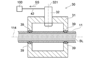
- FIG. 2 is a cross-sectional view showing a pressure detection device according to a first embodiment of the present invention.
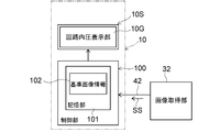
- FIG. 3 is a block diagram showing an electrical connection between a controller and a pressure detection device.
- the pressure detection device 30 includes a main body 31 as a housing, an image acquisition unit 32, and a control unit 100 provided in the controller 10.
- the control unit 100 may be provided not in the controller 10 but in the main unit 31.
- the main body portion 31 has, for example, a shape such as a rectangular parallelepiped or a cylinder, and has a structure in which the tube 11 (12, 15) can penetrate inside.
- the material of the main body portion 31 may be a rigid material capable of holding the blood removal tube 11, the blood feeding tube 12, and the connection tube 15 or elastically deforming in the inserted state, in particular It is not limited.
- a material of the main-body part 31 a metal, a plastics, etc. are mentioned, for example.
- the material of the main body 31 includes, for example, a metal such as aluminum or stainless steel.
- the material of the main body 31 includes a plastic such as polyacetal (POM), polybutylene terephthalate (PBT), or polyethylene terephthalate (PET).
- a plastic such as polyacetal (POM), polybutylene terephthalate (PBT), or polyethylene terephthalate (PET).
- POM polyacetal
- PBT polybutylene terephthalate
- PET polyethylene terephthalate
- the main body portion 31 has a non-slip 39 such as an O-ring formed of rubber, for example.
- the slip stopper 39 is fixed inside the insertion hole of the main body portion 31 through which the tube 11 passes, and prevents the portion of the tube 11 mounted on the main body portion 31 from extending or moving in the direction of the axis 114 of the tube 11 . Thereby, even if the pressure of the medium BL such as blood in the tube 11 fluctuates, the pressure detection device 30 can more accurately and more stably the pressure in the tube 11 of the medium BL circulating in the circuit. Can be detected.
- the image acquisition unit 32 is provided in the main unit 31.
- the image acquisition unit 32 is fixed to the main body 31 in a state in which the axis 321 of the image acquisition unit 32 intersects (specifically, is orthogonal to) the axis 114 of the tube 11.
- the image acquiring unit 32 acquires image information of a pressure receiving unit that is deformed by receiving the pressure of the medium BL in the tube 11. Details of the pressure receiving unit will be described later.
- Examples of the image acquisition unit 32 include a camera using a charge-coupled device (CCD) image sensor, a complementary metal oxide semiconductor (CMOS) image sensor, or the like.
- CCD charge-coupled device
- CMOS complementary metal oxide semiconductor
- the image acquisition unit 32 is electrically connected to the control unit 100 of the controller 10 via the signal line 42.
- a signal SS related to image information acquired (captured) by the image acquisition unit 32 is transmitted to the control unit 100 via the signal line 42.
- the controller 10 has a display unit 10S such as a liquid crystal display device.
- the display unit 10S has a circuit internal pressure display unit 10G. The circuit internal pressure is displayed on the circuit internal pressure display unit 10G of the controller 10.
- the control unit 100 has a storage unit 101.
- the storage unit 101 stores (stores) the reference image information 102.
- the reference image information 102 is information for converting the image information acquired by the image acquisition unit 32 into pressure information related to the pressure of the medium BL in the tube 11. That is, the reference image information 102 is correlation data indicating the relationship between the image information acquired by the image acquisition unit 32 and the pressure information related to the pressure of the medium BL in the tube 11.
- the reference image information 102 may be a table for converting image information into pressure information.
- the reference image information 102 may be an equation based on a graph indicating the relationship between the image information and the pressure information.
- the control unit 100 converts the image information acquired by the image acquisition unit 32 into pressure information related to the pressure of the medium BL in the tube 11. That is, the control unit 100 calculates the pressure of the medium BL in the tube 11 based on the image information acquired by the image acquisition unit 32. Specifically, based on the reference image information 102 stored in the storage unit 101, the control unit 100 converts the image information acquired by the image acquisition unit 32 into pressure information related to the pressure of the medium BL in the tube 11. .
- the conversion processing of the control unit 100 will be further described with reference to the drawings.
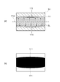
- FIG. 4 and FIG. 5 are diagrams showing image information acquired by the image acquiring unit of the present embodiment.
- FIG. 4A is a plan view showing the image information acquired by the image acquiring unit of the present embodiment when the pressure in the tube is a positive pressure.
- FIG. 4B illustrates an example of a binary image obtained by the binarization process performed by the control unit of the present embodiment based on the image information shown in FIG. 4A.
- FIG. 5A is a plan view showing image information acquired by the image acquiring unit of the present embodiment when the pressure in the tube is a negative pressure.
- FIG. 5B illustrates an example of a binary image obtained by the binarization process performed by the control unit of the present embodiment based on the image information shown in FIG. 5A.
- the pressure in the tube 11 when the medium BL does not flow in the tube 11 is a reference pressure (zero pressure)
- the inside of the circuit of the medium BL passing through the tube 11 is When the pressure becomes positive, the outer diameter of the tube 11 becomes larger than the outer diameter when the pressure in the circuit is at the reference pressure.
- the pressure detection device 30 detects such a change in the shape of the outer diameter portion 111 of the tube 11 and calculates pressure information. That is, in the example shown in FIG. 4A to FIG. 5B, the outer diameter portion 111 of the tube 11 corresponds to the “pressure receiving portion” of the present invention.
- the control unit 100 executes a binarization process of the image information acquired by the image acquisition unit 32. That is, the control unit 100 executes the binarization processing of the image information based on the signal SS related to the image information received from the image acquisition unit 32 via the signal line 42.
- the binary image obtained by the binarization processing of the image information shown in FIG. 4A is as shown in FIG. 4B.
- the binary image obtained by the binarization processing of the image information shown in FIG. 5 (a) is as shown in FIG. 5 (b).
- control unit 100 calculates the area of the outer diameter portion 111 of the tube 11 projected on a plane that intersects (specifically, is orthogonal to) the axis 321 of the image acquisition unit 32.
- the control unit 100 blacks the binary image obtained by the binarization processing of the image information acquired by the image acquisition unit 32. Calculate the area of the part.
- the reference image information 102 stored in the storage unit 101 is the area of the black portion of the binary image obtained by the binarization processing of the image information when the pressure in the circuit is the reference pressure (zero pressure). Including. Therefore, in the control unit 100, the area of the black portion of the binary image obtained by the binarization processing of the image information when the pressure in the circuit is at least one of positive pressure and negative pressure, and the pressure in the circuit The area of the black portion of the binary image obtained by the binarization process of the image information at the reference pressure is compared with that of the binary image.
- control unit 100 controls the variation value of the area of the black part of the binary image obtained by the binarization processing of the image information acquired by the image acquisition unit 32 and the pressure information on the pressure of the medium BL in the tube 11
- the pressure information is calculated based on the reference image information 102 as correlation data indicating the relationship of. That is, the control unit 100 calculates pressure information in accordance with the change in the area of the outer diameter portion 111 of the tube 11 projected on a plane intersecting with the axis 321 of the image acquisition unit 32.
- the control unit 100 converts the image information acquired by the image acquisition unit 32 into pressure information related to the pressure of the medium BL in the tube 11. That is, the pressure detection device 30 is not a load detection element that contacts the tube and measures the repulsive force of the tube, but image information of a pressure receiving portion (in the present embodiment, the outer diameter portion 111 of the tube 11) that deforms under pressure.
- the pressure of the medium BL in the tube 11 is detected by acquiring and converting it into pressure information. Therefore, when the pressure detection device 30 breaks down, an image acquisition error and a reading error occur, and the pressure of the medium BL in the tube 11 is not displayed on the circuit internal pressure display unit 10G.
- the pressure detection device 30 detects the pressure of the medium BL in the tube 11 without contacting the medium BL flowing in the tube 11. This can suppress, for example, the infarcted part of blood or the formation of thrombi in the tube 11. In addition, the operation of removing air bubbles from the inside of the tube 11 (bubble removal operation) is simplified.
- the control unit 100 also converts image information into pressure information based on reference image information 102 indicating the relationship between the image information and the pressure information. Therefore, the pressure detection device 30 can simplify the process of calculating the pressure of the medium BL in the tube 11, and can accurately detect the pressure of the medium BL in the tube 11 in a shorter time.
- control unit 100 calculates pressure information according to the change in the area of the outer diameter portion 111 of the tube 11 projected on a plane intersecting with the axis 321 of the image acquisition unit 32. Therefore, the pressure detection device 30 can detect the pressure of the medium BL in the tube 11 by a relatively simple method of capturing the change in the shape of the outer diameter portion 111 of the tube 11.
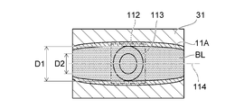
- FIG. 6 and FIG. 7 are diagrams showing image information acquired by the image acquisition unit in the modification of the present embodiment.
- FIG. 6 is a top view showing the image information which the image acquisition part acquired, when the pressure in a tube is positive pressure.
- FIG. 7 is a plan view showing image information acquired by the image acquiring unit when the pressure in the tube is a negative pressure.
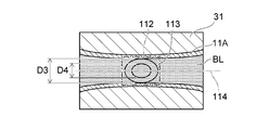
- the tube 11A of this modification has a pattern portion 112 in which a predetermined pattern 113 is provided on the surface of the tube 11A.
- the pattern 113 is, for example, circular.
- the shape of the pattern 113 is not limited to a circle, and may be, for example, a square or a triangle.
- the diameters D1 and D2 of the pattern 113 when the pressure in the circuit is a positive pressure are larger than the diameter of the pattern 113 when the pressure in the circuit is a reference pressure.
- the diameters D1 and D2 are the diameters of the pattern 113 in the direction orthogonal to the axis 114 of the tube 11A.
- the outer diameter of the tube 11 becomes smaller than the outer diameter when the pressure in the circuit is the reference pressure. Therefore, as shown in FIG. 7, the diameters D3 and D4 of the pattern 113 when the pressure in the circuit is a negative pressure are smaller than the diameter of the pattern 113 when the pressure in the circuit is a reference pressure.
- the diameters D3 and D4 are the diameters of the pattern 113 in the direction orthogonal to the axis 114 of the tube 11A.
- the pressure detection device 30 detects such deformation of the pattern 113 of the pattern portion 112 and calculates pressure information. That is, in this modification, the design portion 112 of the tube 11A corresponds to the "pressure receiving portion" of the present invention.
- the control unit 100 calculates the diameter of the pattern 113 in the direction orthogonal to the axis 114 of the tube 11A based on the image information acquired by the image acquisition unit 32.
- the reference image information 102 stored in the storage unit 101 includes the diameter of the pattern 113 in the direction orthogonal to the axis 114 of the tube 11A when the pressure in the circuit is the reference pressure (zero pressure).
- the control unit 100 compares the diameter of the pattern 113 when the pressure in the circuit is at least one of positive pressure and negative pressure with the diameter of the pattern 113 when the pressure in the circuit is a reference pressure.
- the control unit 100 uses correlation data indicating the relationship between the variation value of the diameter of the pattern 113 calculated based on the image information acquired by the image acquisition unit 32 and the pressure information on the pressure of the medium BL in the tube 11.
- the pressure information is calculated based on the reference image information 102 of FIG. That is, the control unit 100 recognizes the pattern 113 of the pattern portion 112, and calculates pressure information according to the deformation of the pattern 113.
- the control unit 100 does not necessarily have to calculate both the outer diameters D1 and D3 of the pattern 113 and the inner diameters D2 and D4 of the pattern 113, and the diameters D1 and D3 of the outer portion of the pattern 113 and the pattern 113 One of the inner diameters D2 and D4 may be calculated.
- the control unit 100 may calculate not the diameter of the pattern 113 of the pattern portion 112 but the area of the area surrounded by the pattern 113 of the pattern portion 112. Then, the control unit 100 uses correlation data indicating the relationship between the fluctuation value of the area of the pattern 113 calculated based on the image information acquired by the image acquisition unit 32 and the pressure information related to the pressure of the medium BL in the tube 11. The pressure information may be calculated based on the reference image information 102 of FIG.
- the control unit 100 recognizes the pattern 113 of the pattern portion 112, and calculates pressure information according to the deformation of the pattern 113. Therefore, the pressure detection device 30 can detect the pressure of the medium BL in the tube 11A by a relatively simple method of capturing the deformation of the pattern 113 of the pattern portion 112. Further, the same effects as the effects described above with reference to FIGS. 1 to 5B can be obtained.
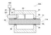
- FIG. 8 is a cross-sectional view showing a pressure detection device according to a second embodiment of the present invention.
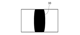
- FIG. 9 is a diagram illustrating an example of a binary image when the pressure in the tube is positive.
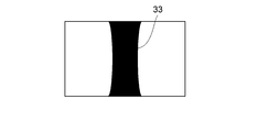
- FIG. 10 is a diagram illustrating an example of a binary image when the pressure in the tube is a negative pressure.
- the pressure detection device 30 ⁇ / b> A includes the main unit 31 as a housing, the image acquisition unit 32, the pressure sensing medium (pressure reception unit) 33, and the control provided in the controller 10. And a unit 100.
- the pressure sensitive medium 33 of the present embodiment corresponds to the "pressure receiving portion" of the present invention.
- the image acquisition unit 32 is fixed to the main body 31 in a state in which the axis 321 of the image acquisition unit 32 is parallel to the axis 114 of the tube 11.
- the pressure detection device 30A according to the present embodiment differs from the pressure detection device 30A according to the first embodiment in that the pressure detection device 30A includes the pressure sensing medium 33 and the axis 321 of the image acquisition unit 32 is parallel to the axis 114 of the tube 11. It differs from the pressure detection apparatus 30 which concerns.
- the other structure is the same as the structure of the pressure detection device 30 according to the first embodiment.
- the pressure-sensitive medium 33 is connected to the main body 31 and the tube 11.
- the pressure-sensitive medium 33 is fixed to the main body 31 by being bonded, fused, or fitted to the main body 31.
- the pressure-sensitive medium 33 is fixed to the tube 11 by being adhered to or fused to the tube 11.
- the pressure-sensitive medium 33 deforms in response to an external force based on the deformation of the tube 11.
- the material of the pressure sensing agent 33 is not particularly limited as long as the pressure sensing agent 33 is deformed by receiving an external force based on the deformation of the tube 11.
- the material of the pressure-sensitive medium 33 include plastics such as polyacetal (POM), polybutylene terephthalate (PBT), and polyethylene terephthalate (PET).
- the material of the pressure-sensitive medium 33 may be a synthetic resin (for example, a vinyl chloride resin, a silicone rubber, etc.) having the same elastically deformable flexibility as the tube 11.
- the control unit 100 executes the binarization processing of the image information based on the signal SS related to the image information received from the image acquisition unit 32 via the signal line 42.
- a binary image obtained by binarizing the image information at this time is as shown in FIG.
- control unit 100 calculates the area of the pressure-sensitive medium 33 projected on a plane which intersects (specifically, is orthogonal to) the axis 321 of the image acquisition unit 32. In other words, in the binary image shown in FIGS. 9 and 10, the control unit 100 calculates the area of the black portion of the binary image obtained by the binarization processing of the image information acquired by the image acquisition unit 32. .
- the reference image information 102 stored in the storage unit 101 is the area of the black portion of the binary image obtained by the binarization processing of the image information when the pressure in the circuit is the reference pressure (zero pressure). Including. Therefore, in the control unit 100, the area of the black portion of the binary image obtained by the binarization processing of the image information when the pressure in the circuit is at least one of positive pressure and negative pressure, and the pressure in the circuit The area of the black portion of the binary image obtained by the binarization process of the image information at the reference pressure is compared with that of the binary image.
- control unit 100 controls the variation value of the area of the black part of the binary image obtained by the binarization processing of the image information acquired by the image acquisition unit 32 and the pressure information on the pressure of the medium BL in the tube 11
- the pressure information is calculated based on the reference image information 102 as correlation data indicating the relationship of. That is, the control unit 100 calculates pressure information in accordance with the change in the area of the pressure sensing medium 33 projected on the plane intersecting with the axis 321 of the image acquisition unit 32.
- the pressure detection device 30A detects the pressure of the medium BL in the tube 11 by a relatively simple method of capturing the change in shape of the pressure-sensitive medium 33 connected to the main body 31 and the tube 11. It can be detected.
- the control unit 100 stores the image information acquired by the image acquisition unit 32 in the tubes 11 and 11A. Convert the pressure information on the pressure of the medium BL in Therefore, when the pressure detection devices 30, 30A fail, an image acquisition error or a reading error occurs, and the pressure of the medium BL in the tubes 11, 11A is not displayed on the circuit internal pressure display unit 10G. That is, it is possible to suppress the display of an erroneous pressure different from the actual pressure of the medium BL on the circuit internal pressure display unit 10G. Thereby, the erroneous detection of the pressure of the medium BL in the tubes 11 and 11A can be suppressed.
- the extracorporeal circulation device 1 includes the tube 11 (12, 15) for transferring the medium BL, and the pressure of the medium BL in the tube 11 (12, 15) provided in the tube 11 (12, 15). And a pressure detection device 30 (30A) for detecting Thereby, the same effect as the effect described above in regard to the pressure detection device 30 (30A) according to the present embodiment is obtained.
- the pressure detection devices 30, 30A are provided at the mounting position W1 in the middle of the blood removal tube 11 of the circulation circuit 1R.
- the effects described above in relation to the present embodiment are that the pressure detection devices 30, 30A are attached at an attachment position W2 in the middle of the blood feeding tube 12 of the circulation circuit 1R and at an intermediate position of the connection tube 15 connecting the centrifugal pump 3 and the oxygenator 2 It is obtained similarly whether it is provided in any position of position W3.
Landscapes
- Health & Medical Sciences (AREA)
- Engineering & Computer Science (AREA)
- Heart & Thoracic Surgery (AREA)
- Physics & Mathematics (AREA)
- Life Sciences & Earth Sciences (AREA)
- Vascular Medicine (AREA)
- General Health & Medical Sciences (AREA)
- General Physics & Mathematics (AREA)
- Cardiology (AREA)
- Theoretical Computer Science (AREA)
- Biomedical Technology (AREA)
- Animal Behavior & Ethology (AREA)
- Veterinary Medicine (AREA)
- Public Health (AREA)
- Computer Vision & Pattern Recognition (AREA)
- Medical Informatics (AREA)
- Hematology (AREA)
- Anesthesiology (AREA)
- Multimedia (AREA)
- Urology & Nephrology (AREA)
- Emergency Medicine (AREA)
- Biophysics (AREA)
- Evolutionary Computation (AREA)
- Molecular Biology (AREA)
- Pathology (AREA)
- Artificial Intelligence (AREA)
- Computing Systems (AREA)
- Databases & Information Systems (AREA)
- Surgery (AREA)
- Software Systems (AREA)
- Physiology (AREA)
- Nuclear Medicine, Radiotherapy & Molecular Imaging (AREA)
- Radiology & Medical Imaging (AREA)
- Quality & Reliability (AREA)
- Electromagnetism (AREA)
- External Artificial Organs (AREA)
- Measuring Fluid Pressure (AREA)
Abstract
【課題】チューブ内における媒体の圧力の誤検知を抑えることができる圧力検知装置を提供すること。 【解決手段】圧力検知装置30は、媒体BLを移送するチューブ11に設置可能とされチューブ11内における媒体BLの圧力を検知する圧力検知装置30であって、チューブ11に装着可能とされた本体部31と、本体部31に設けられ、チューブ11内における媒体BLの圧力を受けて変形する受圧部の画像情報を取得する画像取得部32と、画像取得部により取得された画像情報を圧力に関する圧力情報に変換する制御部100と、を備える。
Description
本発明は、血液等の媒体を通すチューブに装着され、チューブ内における媒体の圧力を検知する圧力検知装置および体外循環装置に関する。
例えば患者の心臓外科手術が行われる場合には、体外循環装置が使用される。体外循環装置では、ポンプが作動して患者の静脈よりチューブを介して脱血し、人工肺により血液中のガス交換や体温調整が行われた後に、患者の動脈もしくは静脈にチューブを介して血液を再び戻す体外血液循環や補助循環等が行われる。体外血液循環や補助循環が適切に行われるために、圧力検知装置を用いて体外循環装置のチューブの回路内の圧力を測定することが必要である。
特許文献1には、体外循環回路の圧力センサが開示されている。特許文献1の図1に示されている圧力センサは、液体室6と、圧力測定手段7と、液体流路8と、を有する。液体流路8は、体外循環回路のチューブの一部から分岐した分岐部として形成され、液体室6の液体流入口40に液密に接続されている。チューブ内を通る液体が、液体流路8から液体室6内に導入され、液体室6の第1の接続面11の側面内周に沿って流入する。液体室6は、液体流路内圧力によって少なくとも一部が変形する変形面20を有している。圧力測定手段7は、変形面20の変形量を測定することで、液体室6内の圧力を測定する。
特許文献1に記載された液体室6は、体外循環回路内の圧力によっては変形しない基準面10と、基準面10に対して離隔配置されて体外循環回路内の圧力によって少なくとも一部が変形する変形面20と、を有する。液体室6は、基準面10と変形面20とを連結していることで、内部には閉鎖された液密な空間を形成している。これにより、液体室6内に液体が流入すると、圧力測定手段7として設けられたロードセル45またはひずみゲージ46は、変形面20の変形より、体外循環回路内の液体の圧力を検知する。
ところが、特許文献1に記載の体外循環回路の圧力センサでは、操作者は、体外循環や補助循環を行っている際に、体外循環回路のチューブの途中において、分岐部である液体流路8を形成して液体室6を接続する。そして、操作者は、液体流路8内と液体室6内とに、液体(血液)を充填する作業が必要である。このように、チューブを通る液体(血液)の回路内の圧力を測定するには、操作者は、治療現場や手術現場において、液体流路8内と液体室6内とに液体を充填する作業を必要とする。そのため、体外循環や補助循環を行っている際に、チューブを通る液体(血液)の回路内の圧力を従来の圧力センサを用いて測定する作業は、容易ではない。また、操作者は、上述したように分岐部である液体流路8をチューブの途中に形成する必要がある。そのため、チューブや液体流路8において、血液の梗塞部分や血栓が生ずるおそれがある。
これに対して、血液等の媒体を移送するチューブの途中に着脱可能に装着される着脱式圧力検知装置が検討されている。このような着脱式圧力検知装置は、例えば、本体部と、本体部に配置された荷重検知素子と、を備える。本体部は、チューブの途中に着脱可能に装着され、チューブを弾性変形させて平坦な面を形成する。荷重検知素子の検知先端部は、チューブに形成された平坦な面に当てられる。これにより、荷重検知素子は、チューブが検知先端部を押し返す力(反発力)を測定することで、媒体が循環される際の回路内圧を媒体に触れることなく測定することができる。
しかし、チューブと接触しチューブの反発力を測定する荷重検知素子を有する圧力検知装置は、故障することがある。圧力検知装置が故障すると、回路内の圧力を誤検知するおそれがある。すなわち、圧力検知装置が故障すると、圧力検知装置により測定された回路内の圧力が、実際の回路内の圧力とは異なることがある。
本発明は、前記課題を解決するためになされたものであり、チューブ内における媒体の圧力の誤検知を抑えることができる圧力検知装置および体外循環装置を提供することを目的とする。
前記課題は、本発明によれば、媒体を移送するチューブに設置可能とされ前記チューブ内における前記媒体の圧力を検知する圧力検知装置であって、前記チューブに装着可能とされた本体部と、前記本体部に設けられ、前記圧力を受けて変形する受圧部の画像情報を取得する画像取得部と、前記画像取得部により取得された前記画像情報を前記圧力に関する圧力情報に変換する制御部と、を備えたことを特徴とする圧力検知装置により解決される。
前記構成によれば、圧力検知装置は、圧力を受けて変形する受圧部の画像情報を取得する画像取得部を備える。そして、制御部は、画像取得部により取得された画像情報をチューブ内における媒体の圧力に関する圧力情報に変換する。つまり、圧力検知装置は、チューブと接触しチューブの反発力を測定する荷重検知素子ではなく、圧力を受けて変形する受圧部の画像情報を取得し圧力情報に変換することにより、チューブ内における媒体の圧力を検知する。そのため、圧力検知装置が故障した場合には、画像の取得エラーや読み取りエラーが発生し、チューブ内における媒体の圧力は表示されない。すなわち、実際の媒体の圧力とは異なる誤った圧力が表示されることを抑えることができる。これにより、チューブ内における媒体の圧力の誤検知を抑えることができる。
また、圧力検知装置は、チューブ内を流れる媒体に接触することなくチューブ内における媒体の圧力を検知する。これにより、例えば血液の梗塞部分や血栓がチューブ内に生ずることを抑えることができる。また、チューブ内から気泡を除去する作業(気泡抜き作業)が簡潔になる。
好ましくは、前記制御部は、前記画像情報と前記圧力情報との関係を示す基準画像情報を格納した記憶部を有し、前記記憶部に格納された前記基準画像情報に基づいて前記画像情報を前記圧力情報に変換することを特徴とする。
前記構成によれば、制御部は、画像情報と圧力情報との関係を示す基準画像情報に基づいて画像情報を圧力情報に変換する。そのため、圧力検知装置は、チューブ内における媒体の圧力を算出する処理を簡易化することができ、チューブ内における媒体の圧力をより短時間で正確に検知することができる。
好ましくは、前記受圧部は、前記チューブの外径部であり、前記制御部は、前記画像取得部の軸に対して交差した平面に投影された前記外径部の面積の変動に応じて前記圧力情報を算出することを特徴とする。
前記構成によれば、制御部は、画像取得部の軸に対して交差した平面に投影されたチューブの外径部の面積の変動に応じて圧力情報を算出する。そのため、圧力検知装置は、チューブの外径部の形状変化を捉えるという比較的簡易的な方法によりチューブ内における媒体の圧力を検知することができる。
好ましくは、前記受圧部は、前記チューブの表面に設けられた所定の模様を有する模様部であり、前記制御部は、前記模様を認識し前記模様の変形に応じて前記圧力情報を算出することを特徴とする。
前記構成によれば、制御部は、チューブの表面に設けられた模様部の模様を認識し模様の変形に応じて圧力情報を算出する。そのため、圧力検知装置は、模様部の模様の変形を捉えるという比較的簡易的な方法によりチューブ内における媒体の圧力を検知することができる。
好ましくは、本発明に係る圧力検知装置は、前記本体部と前記チューブとに接続され、前記チューブの変形に基づく外力を受けて変形する前記受圧部としての感圧媒介をさらに備え、前記制御部は、前記画像取得部の軸に対して交差した平面に投影された前記感圧媒介の面積の変動に応じて前記圧力情報を算出することを特徴とする。
前記構成によれば、圧力検知装置は、チューブの変形に基づく外力を受けて変形する受圧部としての感圧媒介をさらに備える。そして、制御部は、画像取得部の軸に対して交差した平面に投影された感圧媒介の面積の変動に応じて圧力情報を算出する。そのため、圧力検知装置は、本体部とチューブとに接続された感圧媒介の形状変化を捉えるという比較的簡易的な方法によりチューブ内における媒体の圧力を検知することができる。
好ましくは、前記本体部は、前記本体部に装着された前記チューブの部分が前記チューブの軸方向に伸びることを抑制する滑り止めを有することを特徴とする。
前記構成によれば、チューブ内における媒体の圧力が変動した場合であっても、本体部が有する滑り止めは、本体部に装着されたチューブの部分がチューブの軸方向に伸びたり移動したりすることを抑制する。そのため、圧力検知装置は、回路を循環中の媒体のチューブ内における圧力をより正確に、より安定的に検知することができる。
前記課題は、本発明によれば、媒体を体外循環させる際に用いられる体外循環装置であって、前記媒体を移送するチューブと、前記チューブに設けられ前記チューブ内における前記媒体の圧力を検知する上記いずれかの圧力検知装置と、を備えたことを特徴とする体外循環装置により解決される。
前記構成によれば、体外循環装置が備える圧力検知装置は、圧力を受けて変形する受圧部の画像情報を取得する画像取得部を有する。そして、制御部は、画像取得部により取得された画像情報をチューブ内における媒体の圧力に関する圧力情報に変換する。つまり、圧力検知装置は、チューブと接触しチューブの反発力を測定する荷重検知素子ではなく、圧力を受けて変形する受圧部の画像情報を取得し圧力情報に変換することにより、チューブ内における媒体の圧力を検知する。そのため、圧力検知装置が故障した場合には、画像の取得エラーや読み取りエラーが発生し、チューブ内における媒体の圧力は表示されない。すなわち、実際の媒体の圧力とは異なる誤った圧力が表示されることを抑えることができる。これにより、チューブ内における媒体の圧力の誤検知を抑えることができる。
また、体外循環装置が備える圧力検知装置は、チューブ内を流れる媒体に接触することなくチューブ内における媒体の圧力を検知する。これにより、例えば血液の梗塞部分や血栓がチューブ内に生ずることを抑えることができる。また、チューブ内から気泡を除去する作業(気泡抜き作業)が簡潔になる。
本発明によれば、回路を循環中の媒体のチューブ内における圧力の誤検知を抑えることができる圧力検知装置および体外循環装置を提供することができる。
以下に、本発明の好ましい実施形態を、図面を参照して詳しく説明する。
なお、以下に説明する実施形態は、本発明の好適な具体例であるから、技術的に好ましい種々の限定が付されているが、本発明の範囲は、以下の説明において特に本発明を限定する旨の記載がない限り、これらの態様に限られるものではない。また、各図面中、同様の構成要素には同一の符号を付して詳細な説明は適宜省略する。
なお、以下に説明する実施形態は、本発明の好適な具体例であるから、技術的に好ましい種々の限定が付されているが、本発明の範囲は、以下の説明において特に本発明を限定する旨の記載がない限り、これらの態様に限られるものではない。また、各図面中、同様の構成要素には同一の符号を付して詳細な説明は適宜省略する。
図1は、本発明の実施形態に係る体外循環装置を表す系統図である。
図1に示す体外循環装置1が行う「体外循環」には、「体外循環動作」と、「補助循環動作」と、が含まれる。体外循環装置1は、「体外循環動作」と「補助循環動作」とのいずれも行うことができる。
図1に示す体外循環装置1が行う「体外循環」には、「体外循環動作」と、「補助循環動作」と、が含まれる。体外循環装置1は、「体外循環動作」と「補助循環動作」とのいずれも行うことができる。
「体外循環動作」とは、例えば心臓外科手術によって一時的に心臓における血液循環が停止されるような場合に、血液の循環動作と、血液に対するガス交換動作(酸素付加および/または二酸化炭素除去)と、が体外循環装置1により行われることをいう。
また、「補助循環動作」とは、体外循環装置1の適用対象である患者Pの心臓が十分な機能を果たせない場合や、肺によるガス交換が十分に行えないような状態において、血液の循環動作と、血液に対するガス交換動作と、が体外循環装置1によっても行われることをいう。
また、「補助循環動作」とは、体外循環装置1の適用対象である患者Pの心臓が十分な機能を果たせない場合や、肺によるガス交換が十分に行えないような状態において、血液の循環動作と、血液に対するガス交換動作と、が体外循環装置1によっても行われることをいう。
図1に示す体外循環装置1は、例えば患者の心臓外科手術を行う場合において、体外循環装置1のポンプを作動して患者の静脈から脱血して、人工肺により血液中のガス交換を行って血液の酸素化を行った後に、酸素化が行われた血液を再び患者の動脈もしくは静脈に戻す人工肺体外血液循環を行うことができる。体外循環装置1は、心臓と肺の代行を行う装置である。
図1に示すように、体外循環装置1は、血液を循環させる循環回路1Rを有している。循環回路1Rは、人工肺2と、遠心ポンプ3と、遠心ポンプ3を駆動するドライブモータ(駆動手段)4と、静脈側カテーテル(脱血側カテーテル)5と、動脈側カテーテル(送血側カテーテル)6と、制御部100を有するコントローラ10と、を有している。また、体外循環装置1は、圧力検知装置30を備える。圧力検知装置30は、本発明の第1実施形態に係る圧力検知装置に相当する。
図1に示すように、静脈側カテーテル(脱血側カテーテル)5は、大腿静脈より挿入され、静脈側カテーテル5の先端が右心房に留置される。動脈側カテーテル(送血側カテーテル)6は、大腿動脈より挿入される。静脈側カテーテル5は、脱血チューブ(脱血ラインともいう)11を介して遠心ポンプ3に接続されている。脱血チューブ11は、血液を送る管路である。
ドライブモータ4がコントローラ10の指令SGに基づいて遠心ポンプ3の動作を開始すると、遠心ポンプ3は、脱血チューブ11から脱血して血液を人工肺2に通した後に、送血チューブ12(送血ラインともいう)を介して患者Pに血液を戻すことができる。
人工肺2は、遠心ポンプ3と送血チューブ12との間に配置されている。人工肺2は、血液に対するガス交換動作(酸素付加および/または二酸化炭素除去)を行う。人工肺2は、例えば膜型人工肺であるが、特に好ましくは中空糸膜型人工肺である。人工肺2には、酸素ガスが酸素ガス供給部13からチューブ14を通じて供給される。送血チューブ12は、人工肺2と動脈側カテーテル6とを接続している管路である。脱血チューブ11および送血チューブ12としては、例えば塩化ビニル樹脂やシリコーンゴム等の透明性の高い、弾性変形可能な可撓性を有する合成樹脂製の管路が使用される。液体である血液は、脱血チューブ11内ではV方向に流れ、送血チューブ12内ではW方向に流れる。
図1に示す循環回路1Rの例では、超音波気泡検出センサ20が、脱血チューブ11の途中において脱血チューブ11の外側に配置されている。また、ファストクランプ17が、送血チューブ12の途中において送血チューブ12の外側に配置されている。超音波気泡検出センサ20は、脱血チューブ11内に送られている血液中に気泡が存在することを検出した場合には、コントローラ10に気泡を検出した検出信号を送る。これにより、ファストクランプ17は、コントローラ10の指令に基づいて、血液が患者P側に送られることを阻止するために送血チューブ12を緊急に閉塞する。
超音波気泡検出センサ20は、血液循環動作中に三方活栓18の誤操作や三方活栓18に接続されたチューブ19の破損等により回路内に気泡が混入された場合に、混入された気泡を検出することができる。超音波気泡検出センサ20が気泡を検出すると、図1のコントローラ10は、アラームによる警報を報知したり、遠心ポンプ3の回転数を低くしたり、あるいは遠心ポンプ3を停止するとともにファストクランプ17に指令を送信しファストクランプ17により送血チューブ12を直ちに閉塞したりして、気泡が患者Pの体内に送られることを阻止する。これにより、コントローラ10は、体外循環装置1の循環回路1Rにおける血液の循環動作の一時停止を行って、気泡が患者Pの人体に混入することを防止する。
本実施形態に係る圧力検知装置30は、図1に示す体外循環装置1の循環回路1Rのチューブ11(12,15)の任意の箇所に装着可能とされている。これにより、体外循環装置1が患者Pに対して体外循環動作や補助循環動作を行う際に、圧力検知装置30は、チューブ11(12,15)内を通る血液等の媒体の循環中の回路内圧を媒体に触れることなく測定することができる。
本実施形態に係る圧力検知装置30が装着される循環回路1Rのチューブの任意の箇所は、例えば次の通りである。
図1に例示するように、圧力検知装置30は、循環回路1Rの脱血チューブ11の途中における装着位置W1、循環回路1Rの送血チューブ12の途中における装着位置W2、および、遠心ポンプ3と人工肺2とを接続する接続チューブ15の途中における装着位置W3の少なくともいずれかに装着可能とされている。
図1に例示するように、圧力検知装置30は、循環回路1Rの脱血チューブ11の途中における装着位置W1、循環回路1Rの送血チューブ12の途中における装着位置W2、および、遠心ポンプ3と人工肺2とを接続する接続チューブ15の途中における装着位置W3の少なくともいずれかに装着可能とされている。
圧力検知装置30は、循環回路1Rの脱血チューブ11の途中における装着位置W1に装着されると、体外循環動作や補助循環動作の際に、脱血チューブ11内を通る血液の循環中の脱血回路内圧を血液に触れることなく測定可能である。これにより、コントローラ10は、脱血チューブ11を介して患者Pから脱血している際に、脱血チューブ11における患者Pの脱血状態の変化のトレンド(圧力の変化の傾向)を把握できる。
また、圧力検知装置30は、循環回路1Rの送血チューブ12の途中における装着位置W2に装着されると、体外循環動作や補助循環動作の際に、送血チューブ12内を通る血液の循環中の送血回路内圧を血液に触れることなく測定可能である。これにより、コントローラ10は、送血チューブ12を介して患者Pへ送血している際に、人工肺2の不調や、送血チューブ12における患者Pの送血状態の変化のトレンド(圧力の変化の傾向)を把握できる。
さらに、圧力検知装置30は、接続チューブ15の途中における装着位置W3に装着されると、体外循環動作や補助循環動作の際に、接続チューブ15を介して遠心ポンプ3により送血されているときの接続チューブ15内を通る血液の循環中の送血回路内圧を血液に触れることなく測定可能である。これにより、コントローラ10は、循環回路1Rにおける遠心ポンプ3の動作の変化のトレンド(圧力の変化の傾向)を検知することができる。
このように、圧力検知装置30は、循環回路1Rの装着位置W1、W2、W3等の任意の位置に対して装着可能とされている。コントローラ10の制御部100は、圧力検知装置30により取得された画像情報に関する信号SSを圧力検知装置30から受信することにより、循環回路1Rを構成している脱血チューブ11(送血チューブ12、接続チューブ15)における血液等の媒体の回路内圧力の変化のトレンド(圧力の変化の傾向)を検知できる。
本実施形態に係る圧力検知装置30は、例えば図1に示す循環回路1Rの脱血チューブ11の途中における装着位置W1、循環回路1Rの送血チューブ12の途中における装着位置W2、および遠心ポンプ3と人工肺2とを接続する接続チューブ15の途中における装着位置W3のいずれの位置においても、同じ要領でチューブ11(12,15)に装着可能な構造を有する。以下の説明では、本実施形態に係る圧力検知装置30が循環回路1Rの脱血チューブ11の途中における装着位置W1に設けられた場合を例に挙げる。また、説明の便宜上、脱血チューブ11を単に「チューブ11」と称することがある。
図2は、本発明の第1実施形態に係る圧力検知装置を表す断面図である。
図3は、コントローラと圧力検知装置との電気的な接続を表すブロック図である。
図3は、コントローラと圧力検知装置との電気的な接続を表すブロック図である。
図2に表したように、本実施形態に係る圧力検知装置30は、ハウジングとしての本体部31と、画像取得部32と、コントローラ10に設けられた制御部100と、を有する。なお、制御部100は、コントローラ10ではなく本体部31に設けられていてもよい。
本体部31は、例えば直方体や円筒などの形状を呈し、チューブ11(12,15)が内部を貫通可能な構造を有する。本体部31の材料は、脱血チューブ11、送血チューブ12、および接続チューブ15を保持したり、嵌め込んだ状態で弾性変形させたりすることができる剛性を有する材料であればよく、特には限定されない。本体部31の材料としては、例えば金属あるいはプラスチックなどが挙げられる。具体的には、本体部31の材料は、例えばアルミニウムやステンレス等の金属を含む。あるいは、本体部31の材料は、ポリアセタール(POM)や、ポリブチレンテレフタレート(PBT)や、ポリエチレンテレフタレート(PET)等のプラスチックを含む。なお、本体部31の材料が透明なプラスチックである場合には、脱血チューブ11、送血チューブ12、および接続チューブ15が本体部31に保持された状態あるいは嵌め込まれた状態を、操作者は、本体部31を通して目視で確認できる。
本体部31は、例えばゴムにより形成されたOリングなどの滑り止め39を有する。滑り止め39は、チューブ11が通る本体部31の挿入孔の内側に固定され、本体部31に装着されたチューブ11の部分がチューブ11の軸114方向に伸びたり移動したりすることを抑制する。これにより、圧力検知装置30は、チューブ11内における血液等の媒体BLの圧力が変動した場合であっても、回路を循環中の媒体BLのチューブ11内における圧力をより正確に、より安定的に検知することができる。
画像取得部32は、本体部31に設けられている。図2に表した例では、画像取得部32は、画像取得部32の軸321がチューブ11の軸114と交差(具体的には直交)する状態で本体部31に固定されている。画像取得部32は、チューブ11内における媒体BLの圧力を受けて変形する受圧部の画像情報を取得する。受圧部の詳細については、後述する。画像取得部32としては、例えば、CCD(Charge-Coupled Device)イメージセンサやCMOS(Complementary Metal Oxide Semiconductor)イメージセンサなどが用いられたカメラが挙げられる。
図3に表したように、画像取得部32は、信号線42を介してコントローラ10の制御部100に電気的に接続されている。画像取得部32が取得(撮像)した画像情報に関する信号SSは、信号線42を介して制御部100に送信される。コントローラ10は、液晶表示装置等の表示部10Sを有する。表示部10Sは、回路内圧表示部10Gを有する。回路内圧は、コントローラ10の回路内圧表示部10Gに表示される。
制御部100は、記憶部101を有する。記憶部101は、基準画像情報102を記憶(格納)している。基準画像情報102は、画像取得部32により取得された画像情報をチューブ11内における媒体BLの圧力に関する圧力情報に変換するための情報である。すなわち、基準画像情報102は、画像取得部32により取得された画像情報と、チューブ11内における媒体BLの圧力に関する圧力情報と、の関係を示す相関データである。例えば、基準画像情報102は、画像情報を圧力情報に変換するテーブルであってもよい。あるいは、基準画像情報102は、画像情報と圧力情報との関係を示すグラフに基づいた数式であってもよい。
制御部100は、画像取得部32により取得された画像情報をチューブ11内における媒体BLの圧力に関する圧力情報に変換する。つまり、制御部100は、画像取得部32により取得された画像情報に基づいてチューブ11内における媒体BLの圧力を算出する。具体的には、制御部100は、記憶部101に格納された基準画像情報102に基づいて、画像取得部32により取得された画像情報をチューブ11内における媒体BLの圧力に関する圧力情報に変換する。制御部100の変換処理について、図面を参照してさらに説明する。
図4および図5は、本実施形態の画像取得部が取得した画像情報を表す図である。
なお、図4(a)は、チューブ内の圧力が陽圧である場合において、本実施形態の画像取得部が取得した画像情報を表す平面図である。図4(b)は、本実施形態の制御部が図4(a)に表した画像情報に基づいて実行した二値化処理により得られた二値画像の一例を例示する図である。図5(a)は、チューブ内の圧力が陰圧である場合において、本実施形態の画像取得部が取得した画像情報を表す平面図である。図5(b)は、本実施形態の制御部が図5(a)に表した画像情報に基づいて実行した二値化処理により得られた二値画像の一例を例示する図である。
なお、図4(a)は、チューブ内の圧力が陽圧である場合において、本実施形態の画像取得部が取得した画像情報を表す平面図である。図4(b)は、本実施形態の制御部が図4(a)に表した画像情報に基づいて実行した二値化処理により得られた二値画像の一例を例示する図である。図5(a)は、チューブ内の圧力が陰圧である場合において、本実施形態の画像取得部が取得した画像情報を表す平面図である。図5(b)は、本実施形態の制御部が図5(a)に表した画像情報に基づいて実行した二値化処理により得られた二値画像の一例を例示する図である。
図4(a)に表したように、媒体BLがチューブ11内を流れていないときのチューブ11内の圧力を基準圧力(ゼロ圧力)とした場合において、チューブ11を通る媒体BLの回路内の圧力が陽圧になると、チューブ11の外径は、回路内の圧力が基準圧力のときの外径よりも大きくなる。一方で、図5(a)に表したように、チューブ11を通る媒体BLの回路内の圧力が陰圧になると、チューブ11の外径は、回路内の圧力が基準圧力のときの外径よりも小さくなる。本実施形態に係る圧力検知装置30は、このようなチューブ11の外径部111の形状変化を捉え圧力情報を算出する。つまり、図4(a)~図5(b)に表した例では、チューブ11の外径部111は、本発明の「受圧部」に相当する。
具体的に説明すると、制御部100は、画像取得部32により取得された画像情報の二値化処理を実行する。つまり、制御部100は、画像取得部32から信号線42を介して受信した画像情報に関する信号SSに基づいて、画像情報の二値化処理を実行する。図4(a)に表した画像情報の二値化処理により得られた二値画像は、図4(b)に表した通りである。図5(a)に表した画像情報の二値化処理により得られた二値画像は、図5(b)に表した通りである。
続いて、制御部100は、画像取得部32の軸321に対して交差(具体的には直交)した平面に投影されたチューブ11の外径部111の面積を算出する。言い換えれば、図4(b)および図5(b)に表した二値画像において、制御部100は、画像取得部32が取得した画像情報の二値化処理により得られた二値画像の黒色部分の面積を算出する。
一方で、記憶部101に記憶された基準画像情報102は、回路内の圧力が基準圧力(ゼロ圧力)のときの画像情報の二値化処理により得られた二値画像の黒色部分の面積を含む。そこで、制御部100は、回路内の圧力が陽圧および陰圧の少なくともいずれかのときの画像情報の二値化処理により得られた二値画像の黒色部分の面積と、回路内の圧力が基準圧力のときの画像情報の二値化処理により得られた二値画像の黒色部分の面積と、を比較する。そして、制御部100は、画像取得部32が取得した画像情報の二値化処理により得られた二値画像の黒色部分の面積の変動値と、チューブ11内における媒体BLの圧力に関する圧力情報と、の関係を示す相関データとしての基準画像情報102に基づいて圧力情報を算出する。つまり、制御部100は、画像取得部32の軸321に対して交差した平面に投影されたチューブ11の外径部111の面積の変動に応じて圧力情報を算出する。
本実施形態に係る圧力検知装置30によれば、制御部100は、画像取得部32により取得された画像情報をチューブ11内における媒体BLの圧力に関する圧力情報に変換する。つまり、圧力検知装置30は、チューブと接触しチューブの反発力を測定する荷重検知素子ではなく、圧力を受けて変形する受圧部(本実施形態ではチューブ11の外径部111)の画像情報を取得し圧力情報に変換することにより、チューブ11内における媒体BLの圧力を検知する。そのため、圧力検知装置30が故障した場合には、画像の取得エラーや読み取りエラーが発生し、チューブ11内における媒体BLの圧力は、回路内圧表示部10Gには表示されない。すなわち、実際の媒体BLの圧力とは異なる誤った圧力が回路内圧表示部10Gに表示されることを抑えることができる。これにより、チューブ11内における媒体BLの圧力の誤検知を抑えることができる。
また、圧力検知装置30は、チューブ11内を流れる媒体BLに接触することなくチューブ11内における媒体BLの圧力を検知する。これにより、例えば血液の梗塞部分や血栓がチューブ11内に生ずることを抑えることができる。また、チューブ11内から気泡を除去する作業(気泡抜き作業)が簡潔になる。
また、制御部100は、画像情報と圧力情報との関係を示す基準画像情報102に基づいて画像情報を圧力情報に変換する。そのため、圧力検知装置30は、チューブ11内における媒体BLの圧力を算出する処理を簡易化することができ、チューブ11内における媒体BLの圧力をより短時間で正確に検知することができる。
さらに、制御部100は、画像取得部32の軸321に対して交差した平面に投影されたチューブ11の外径部111の面積の変動に応じて圧力情報を算出する。そのため、圧力検知装置30は、チューブ11の外径部111の形状変化を捉えるという比較的簡易的な方法によりチューブ11内における媒体BLの圧力を検知することができる。
次に、本実施形態の受圧部の変形例を、図面を参照して説明する。
図6および図7は、本実施形態の変形例において、画像取得部が取得した画像情報を表す図である。
なお、図6は、チューブ内の圧力が陽圧である場合において、画像取得部が取得した画像情報を表す平面図である。図7は、チューブ内の圧力が陰圧である場合において、画像取得部が取得した画像情報を表す平面図である。
図6および図7は、本実施形態の変形例において、画像取得部が取得した画像情報を表す図である。
なお、図6は、チューブ内の圧力が陽圧である場合において、画像取得部が取得した画像情報を表す平面図である。図7は、チューブ内の圧力が陰圧である場合において、画像取得部が取得した画像情報を表す平面図である。
本変形例のチューブ11Aは、チューブ11Aの表面に所定の模様113が設けられた模様部112を有する。回路内の圧力が基準圧力のときに画像取得部32により取得された画像情報では、模様113は、例えば円形である。但し、模様113の形状は、円形だけには限定されず、例えば四角形や三角形などであってもよい。図4(a)~図5(b)に関して前述したように、チューブ11を通る媒体BLの回路内の圧力が陽圧になると、チューブ11の外径は、回路内の圧力が基準圧力のときの外径よりも大きくなる。そのため、図6に表したように、回路内の圧力が陽圧のときの模様113の径D1、D2は、回路内の圧力が基準圧力のときの模様113の径よりも大きい。例えば、径D1、D2は、チューブ11Aの軸114に対して直交する方向の模様113の径である。一方で、チューブ11を通る媒体BLの回路内の圧力が陰圧になると、チューブ11の外径は、回路内の圧力が基準圧力のときの外径よりも小さくなる。そのため、図7に表したように、回路内の圧力が陰圧のときの模様113の径D3、D4は、回路内の圧力が基準圧力のときの模様113の径よりも小さい。例えば、径D3、D4は、チューブ11Aの軸114に対して直交する方向の模様113の径である。本変形例では、圧力検知装置30は、このような模様部112の模様113の変形を捉え圧力情報を算出する。つまり、本変形例では、チューブ11Aの模様部112は、本発明の「受圧部」に相当する。
具体的に説明すると、制御部100は、画像取得部32により取得された画像情報に基づいて、チューブ11Aの軸114に対して直交する方向の模様113の径を算出する。一方で、記憶部101に記憶された基準画像情報102は、回路内の圧力が基準圧力(ゼロ圧力)のときのチューブ11Aの軸114に対して直交する方向の模様113の径を含む。制御部100は、回路内の圧力が陽圧および陰圧の少なくともいずれかのときの模様113の径と、回路内の圧力が基準圧力のときの模様113の径と、を比較する。そして、制御部100は、画像取得部32が取得した画像情報に基づいて算出した模様113の径の変動値と、チューブ11内における媒体BLの圧力に関する圧力情報と、の関係を示す相関データとしての基準画像情報102に基づいて圧力情報を算出する。つまり、制御部100は、模様部112の模様113を認識し、模様113の変形に応じて圧力情報を算出する。
なお、制御部100は、必ずしも、模様113の外側の径D1、D3および模様113の内側の径D2、D4の両方を算出しなくともよく、模様113の外側の径D1、D3および模様113の内側の径D2、D4のいずれか一方を算出してもよい。あるいは、制御部100は、模様部112の模様113の径ではなく、模様部112の模様113で囲まれた領域の面積を算出してもよい。そして、制御部100は、画像取得部32が取得した画像情報に基づいて算出した模様113の面積の変動値と、チューブ11内における媒体BLの圧力に関する圧力情報と、の関係を示す相関データとしての基準画像情報102に基づいて圧力情報を算出してもよい。
本変形例によれば、制御部100は、模様部112の模様113を認識し、模様113の変形に応じて圧力情報を算出する。そのため、圧力検知装置30は、模様部112の模様113の変形を捉えるという比較的簡易的な方法によりチューブ11A内における媒体BLの圧力を検知することができる。また、図1~図5(b)に関して前述した効果と同様の効果が得られる。
次に、本発明の第2実施形態について説明する。
なお、第2実施形態に係る圧力検知装置30Aの構成要素が、図1~図7に関して前述した第1実施形態に係る圧力検知装置30の構成要素と同様である場合には、重複する説明は適宜省略し、以下、相違点を中心に説明する。
なお、第2実施形態に係る圧力検知装置30Aの構成要素が、図1~図7に関して前述した第1実施形態に係る圧力検知装置30の構成要素と同様である場合には、重複する説明は適宜省略し、以下、相違点を中心に説明する。
図8は、本発明の第2実施形態に係る圧力検知装置を表す断面図である。
図9は、チューブ内の圧力が陽圧であるときの二値画像の一例を例示する図である。
図10は、チューブ内の圧力が陰圧であるときの二値画像の一例を例示する図である。
図9は、チューブ内の圧力が陽圧であるときの二値画像の一例を例示する図である。
図10は、チューブ内の圧力が陰圧であるときの二値画像の一例を例示する図である。
図8に表したように、本実施形態に係る圧力検知装置30Aは、ハウジングとしての本体部31と、画像取得部32と、感圧媒介(受圧部)33と、コントローラ10に設けられた制御部100と、を有する。本実施形態の感圧媒介33は、本発明の「受圧部」に相当する。画像取得部32は、画像取得部32の軸321がチューブ11の軸114と平行な状態で本体部31に固定されている。圧力検知装置30Aが感圧媒介33を備える点、および画像取得部32の軸321がチューブ11の軸114と平行である点において、本実施形態に係る圧力検知装置30Aは、第1実施形態に係る圧力検知装置30とは異なる。その他の構造は、第1実施形態に係る圧力検知装置30の構造と同様である。
感圧媒介33は、本体部31とチューブ11とに接続されている。例えば、感圧媒介33は、本体部31に接着されたり、融着されたり、嵌合されたりすることで、本体部31に固定されている。また、感圧媒介33は、チューブ11に接着されたり、融着されたりすることで、チューブ11に固定されている。感圧媒介33は、チューブ11の変形に基づく外力を受けて変形する。感圧媒介33の材料は、感圧媒介33がチューブ11の変形に基づく外力を受けて変形する限りにおいて特には限定されない。感圧媒介33の材料としては、例えば、ポリアセタール(POM)や、ポリブチレンテレフタレート(PBT)や、ポリエチレンテレフタレート(PET)等のプラスチックが挙げられる。あるいは、感圧媒介33の材料は、チューブ11と同様の弾性変形可能な可撓性を有する合成樹脂(例えば塩化ビニル樹脂やシリコーンゴム等)であってもよい。
図4(a)~図5(b)に関して前述したように、チューブ11を通る媒体BLの回路内の圧力が陽圧になると、チューブ11の外径は、回路内の圧力が基準圧力のときの外径よりも大きくなる。そうすると、本体部31とチューブ11との間の空間は、回路内の圧力が基準圧力のときの空間よりも狭くなる。そのため、感圧媒介33は、チューブ11の膨張変形に基づく外力を受けて圧縮変形する。そして、制御部100は、画像取得部32から信号線42を介して受信した画像情報に関する信号SSに基づいて、画像情報の二値化処理を実行する。このときに画像情報の二値化処理により得られた二値画像は、図9に表した通りである。
一方で、チューブ11を通る媒体BLの回路内の圧力が陰圧になると、チューブ11の外径は、回路内の圧力が基準圧力のときの外径よりも小さくなる。そうすると、本体部31とチューブ11との間の空間は、回路内の圧力が基準圧力のときの空間よりも広くなる。そのため、感圧媒介33は、チューブ11の収縮変形に基づく外力を受けて伸張変形する。そして、制御部100は、画像取得部32から信号線42を介して受信した画像情報に関する信号SSに基づいて、画像情報の二値化処理を実行する。このときに画像情報の二値化処理により得られた二値画像は、図10に表した通りである。
続いて、制御部100は、画像取得部32の軸321に対して交差(具体的には直交)した平面に投影された感圧媒介33の面積を算出する。言い換えれば、図9および図10に表した二値画像において、制御部100は、画像取得部32が取得した画像情報の二値化処理により得られた二値画像の黒色部分の面積を算出する。
一方で、記憶部101に記憶された基準画像情報102は、回路内の圧力が基準圧力(ゼロ圧力)のときの画像情報の二値化処理により得られた二値画像の黒色部分の面積を含む。そこで、制御部100は、回路内の圧力が陽圧および陰圧の少なくともいずれかのときの画像情報の二値化処理により得られた二値画像の黒色部分の面積と、回路内の圧力が基準圧力のときの画像情報の二値化処理により得られた二値画像の黒色部分の面積と、を比較する。そして、制御部100は、画像取得部32が取得した画像情報の二値化処理により得られた二値画像の黒色部分の面積の変動値と、チューブ11内における媒体BLの圧力に関する圧力情報と、の関係を示す相関データとしての基準画像情報102に基づいて圧力情報を算出する。つまり、制御部100は、画像取得部32の軸321に対して交差した平面に投影された感圧媒介33の面積の変動に応じて圧力情報を算出する。
本実施形態によれば、圧力検知装置30Aは、本体部31とチューブ11とに接続された感圧媒介33の形状変化を捉えるという比較的簡易的な方法によりチューブ11内における媒体BLの圧力を検知することができる。
以上説明したように、第1実施形態に係る圧力検知装置30および第2実施形態に係る圧力検知装置30Aにおいて、制御部100は、画像取得部32により取得された画像情報をチューブ11、11A内における媒体BLの圧力に関する圧力情報に変換する。そのため、圧力検知装置30、30Aが故障した場合には、画像の取得エラーや読み取りエラーが発生し、チューブ11、11A内における媒体BLの圧力は、回路内圧表示部10Gには表示されない。すなわち、実際の媒体BLの圧力とは異なる誤った圧力が回路内圧表示部10Gに表示されることを抑えることができる。これにより、チューブ11、11A内における媒体BLの圧力の誤検知を抑えることができる。
また、本実施形態に係る体外循環装置1は、媒体BLを移送するチューブ11(12、15)と、チューブ11(12、15)に設けられチューブ11(12、15)内における媒体BLの圧力を検知する圧力検知装置30(30A)と、を備える。これにより、本実施形態に係る圧力検知装置30(30A)に関して前述した効果と同様の効果が得られる。
以上、本発明の実施形態について説明した。しかし、本発明は、上記実施形態に限定されず、特許請求の範囲を逸脱しない範囲で種々の変更を行うことができる。上記実施形態の構成は、その一部を省略したり、上記とは異なるように任意に組み合わせたりすることができる。本実施形態では、圧力検知装置30、30Aが循環回路1Rの脱血チューブ11の途中における装着位置W1に設けられた場合を例に挙げた。本実施形態に関して前述した効果は、圧力検知装置30、30Aが循環回路1Rの送血チューブ12の途中における装着位置W2、および遠心ポンプ3と人工肺2とを接続する接続チューブ15の途中における装着位置W3のいずれの位置に設けられた場合であっても、同様に得られる。
1・・・体外循環装置、 1R・・・循環回路、 2・・・人工肺、 3・・・遠心ポンプ、 4・・・ドライブモータ、 5・・・静脈側カテーテル、 6・・・動脈側カテーテル、 10・・・コントローラ、 10G・・・回路内圧表示部、 10S・・・表示部、 11、11A・・・脱血チューブ、 12・・・送血チューブ、 13・・・酸素ガス供給部、 14・・・チューブ、 15・・・接続チューブ、 17・・・ファストクランプ、 18・・・三方活栓、 19・・・チューブ、 20・・・超音波気泡検出センサ、 30、30A・・・圧力検知装置、 31・・・本体部、 32・・・画像取得部、 33・・・感圧媒介、 39・・・滑り止め、 42・・・信号線、 100・・・制御部、 101・・・記憶部、 102・・・基準画像情報、 111・・・外径部、 112・・・模様部、 113・・・模様、 114、321・・・軸、 BL・・・媒体、 P・・・患者、 SG・・・指令、 SS・・・信号、 W1、W2、W3・・・装着位置
Claims (7)
- 媒体を移送するチューブに設置可能とされ前記チューブ内における前記媒体の圧力を検知する圧力検知装置であって、
前記チューブに装着可能とされた本体部と、
前記本体部に設けられ、前記圧力を受けて変形する受圧部の画像情報を取得する画像取得部と、
前記画像取得部により取得された前記画像情報を前記圧力に関する圧力情報に変換する制御部と、
を備えたことを特徴とする圧力検知装置。 - 前記制御部は、前記画像情報と前記圧力情報との関係を示す基準画像情報を格納した記憶部を有し、前記記憶部に格納された前記基準画像情報に基づいて前記画像情報を前記圧力情報に変換することを特徴とする請求項1に記載の圧力検知装置。
- 前記受圧部は、前記チューブの外径部であり、
前記制御部は、前記画像取得部の軸に対して交差した平面に投影された前記外径部の面積の変動に応じて前記圧力情報を算出することを特徴とする請求項1または2に記載の圧力検知装置。 - 前記受圧部は、前記チューブの表面に設けられた所定の模様を有する模様部であり、
前記制御部は、前記模様を認識し前記模様の変形に応じて前記圧力情報を算出することを特徴とする請求項1または2に記載の圧力検知装置。 - 前記本体部と前記チューブとに接続され、前記チューブの変形に基づく外力を受けて変形する前記受圧部としての感圧媒介をさらに備え、
前記制御部は、前記画像取得部の軸に対して交差した平面に投影された前記感圧媒介の面積の変動に応じて前記圧力情報を算出することを特徴とする請求項1または2に記載の圧力検知装置。 - 前記本体部は、前記本体部に装着された前記チューブの部分が前記チューブの軸方向に伸びることを抑制する滑り止めを有することを特徴とする請求項1~5のいずれか1項に記載の圧力検知装置。
- 媒体を体外循環させる際に用いられる体外循環装置であって、
前記媒体を移送するチューブと、
前記チューブに設けられ前記チューブ内における前記媒体の圧力を検知する請求項1~6のいずれか1項に記載の圧力検知装置と、
を備えたことを特徴とする体外循環装置。
Priority Applications (4)
| Application Number | Priority Date | Filing Date | Title |
|---|---|---|---|
| CN201880009449.0A CN110234971A (zh) | 2017-07-10 | 2018-07-05 | 压力检测装置及体外循环装置 |
| EP18832040.2A EP3654007A4 (en) | 2017-07-10 | 2018-07-05 | PRESSURE DETECTION DEVICE AND DEVICE FOR EXTRACORPORAL CIRCULATION |
| JP2019529094A JP7208897B2 (ja) | 2017-07-10 | 2018-07-05 | 圧力検知装置および体外循環装置 |
| US16/702,792 US11278656B2 (en) | 2017-07-10 | 2019-12-04 | Pressure measuring device and extracorporeal circulator |
Applications Claiming Priority (2)
| Application Number | Priority Date | Filing Date | Title |
|---|---|---|---|
| JP2017-134750 | 2017-07-10 | ||
| JP2017134750 | 2017-07-10 |
Related Child Applications (1)
| Application Number | Title | Priority Date | Filing Date |
|---|---|---|---|
| US16/702,792 Continuation US11278656B2 (en) | 2017-07-10 | 2019-12-04 | Pressure measuring device and extracorporeal circulator |
Publications (1)
| Publication Number | Publication Date |
|---|---|
| WO2019013089A1 true WO2019013089A1 (ja) | 2019-01-17 |
Family
ID=65001982
Family Applications (1)
| Application Number | Title | Priority Date | Filing Date |
|---|---|---|---|
| PCT/JP2018/025494 WO2019013089A1 (ja) | 2017-07-10 | 2018-07-05 | 圧力検知装置および体外循環装置 |
Country Status (5)
| Country | Link |
|---|---|
| US (1) | US11278656B2 (ja) |
| EP (1) | EP3654007A4 (ja) |
| JP (1) | JP7208897B2 (ja) |
| CN (1) | CN110234971A (ja) |
| WO (1) | WO2019013089A1 (ja) |
Families Citing this family (5)
| Publication number | Priority date | Publication date | Assignee | Title |
|---|---|---|---|---|
| JP2020039020A (ja) * | 2018-09-03 | 2020-03-12 | ソニーセミコンダクタソリューションズ株式会社 | 画像処理装置および画像処理方法 |
| CN111166490B (zh) * | 2020-02-25 | 2020-11-27 | 青岛大学附属医院 | 医疗机器人压力检测方法及医疗机器人 |
| CN111282060A (zh) * | 2020-03-18 | 2020-06-16 | 上海市东方医院(同济大学附属东方医院) | 一种体外膜肺氧合装置 |
| CN112382377A (zh) * | 2020-11-09 | 2021-02-19 | 深圳市赛恒尔医疗科技有限公司 | 一种体外循环机及辅助参数调节方法和系统 |
| CN113804248B (zh) * | 2021-08-24 | 2023-09-22 | 中国石油大学(华东) | 利用数字散斑和有限元技术的无损地应力测试装置及方法 |
Citations (6)
| Publication number | Priority date | Publication date | Assignee | Title |
|---|---|---|---|---|
| JPS5728347U (ja) * | 1980-07-23 | 1982-02-15 | ||
| US4911015A (en) * | 1988-11-14 | 1990-03-27 | Asea Brown Boveri Inc. | Non-electrical monitoring of a physical condition |
| JPH0712661A (ja) * | 1990-08-20 | 1995-01-17 | Univ Washington | 表面上の酸素含有気体の圧力を測定する方法、表面上の酸素含有気体を可視化する方法および感圧組成 |
| JP2004317479A (ja) * | 2002-09-26 | 2004-11-11 | Mitsubishi Materials Corp | 密閉缶の検査方法及び検査装置並びに密閉缶を梱包したケース |
| WO2007123156A1 (ja) | 2006-04-19 | 2007-11-01 | Asahi Kasei Kuraray Medical Co., Ltd. | 体外循環回路の圧力センサ |
| US20090009764A1 (en) * | 2007-07-05 | 2009-01-08 | Baxter International Inc. | Method and apparatus for measuring the presence and concentration of pharmaceutical substances in a medical fluid administered by a medication delivery system |
Family Cites Families (21)
| Publication number | Priority date | Publication date | Assignee | Title |
|---|---|---|---|---|
| JPH0523393A (ja) * | 1991-07-18 | 1993-02-02 | Joji Oshima | 血圧測定装置 |
| CN1265201C (zh) * | 2003-03-21 | 2006-07-19 | 中国科学院过程工程研究所 | 一种在线测量高温熔体表面张力、接触角和密度的装置 |
| CN1249414C (zh) * | 2004-03-25 | 2006-04-05 | 上海交通大学 | 基于视觉的低速旋转轴的扭矩动态测量装置 |
| JP2005283204A (ja) * | 2004-03-29 | 2005-10-13 | Terumo Corp | シリンジ外筒内の摺動性物質塗布検査方法およびシリンジ外筒内の摺動性物質塗布検査装置 |
| EP1818664B1 (de) * | 2006-02-13 | 2013-05-01 | F.Hoffmann-La Roche Ag | Vorrichtung zur Erkennung einer Druckänderung im Flüssigkeitspfad einer Mikrodosiervorrichtung |
| EP1892001A1 (de) * | 2006-08-23 | 2008-02-27 | B. Braun Medizintechnologie GmbH | Medizinisches Gerät zur extrakorporalen Blutbehandlung |
| AU2009235064A1 (en) * | 2008-04-09 | 2009-10-15 | F.Hoffmann-La Roche Ag | Modular skin-adherable system for medical fluid delivery |
| DE102009001901A1 (de) * | 2009-03-26 | 2010-09-30 | Robert Bosch Gmbh | Blutbehandlungsvorrichtung |
| US9677555B2 (en) * | 2011-12-21 | 2017-06-13 | Deka Products Limited Partnership | System, method, and apparatus for infusing fluid |
| US9320842B2 (en) * | 2011-04-29 | 2016-04-26 | Medtronic, Inc. | Multimodal dialysis system |
| EP2557407B1 (en) * | 2011-08-12 | 2020-02-12 | Fenwal, Inc. | A blood processing system and method |
| US10463259B2 (en) * | 2011-10-28 | 2019-11-05 | Three Rivers Cardiovascular Systems Inc. | System and apparatus comprising a multi-sensor catheter for right heart and pulmonary artery catheterization |
| US9186470B2 (en) * | 2012-02-08 | 2015-11-17 | Apple Inc. | Shape reflector and surface contour mapping |
| KR101348109B1 (ko) * | 2012-06-18 | 2014-01-16 | 포항공과대학교 산학협력단 | 체외 혈액 순환 장치, 및 심혈관 질환 연구 방법 |
| US9510766B2 (en) * | 2013-03-13 | 2016-12-06 | Mississippi State University (Msu) | Insertable probe |
| DE102013012469A1 (de) * | 2013-07-09 | 2015-01-15 | Fresenius Medical Care Deutschland Gmbh | Verfahren zur Messung des Verlaufs von Druckpulswellen bei einer extrakorporalen Blutbehandlung und Vorrichtung zur Durchführung des Verfahrens |
| JPWO2015141622A1 (ja) * | 2014-03-17 | 2017-04-06 | テルモ株式会社 | 警報装置、体外循環装置及び警報装置の制御方法 |
| CN103994724B (zh) * | 2014-05-13 | 2019-07-02 | 滕军 | 基于数字图像处理技术的结构二维位移及应变监测方法 |
| EP3231461B1 (en) * | 2014-12-12 | 2019-08-14 | Terumo Kabushiki Kaisha | Extracorporeal circulation device |
| EP3392632B1 (en) | 2015-12-14 | 2022-10-12 | Terumo Kabushiki Kaisha | Removable pressure sensor and extracorporeal circulation device provided with removable pressure sensor |
| BR112019012214A8 (pt) * | 2016-12-15 | 2023-03-28 | Baxter Int | Sistema e método para monitorar e determinar parâmetros do paciente a partir de forma de onda venosa detectada |
-
2018
- 2018-07-05 JP JP2019529094A patent/JP7208897B2/ja active Active
- 2018-07-05 CN CN201880009449.0A patent/CN110234971A/zh active Pending
- 2018-07-05 WO PCT/JP2018/025494 patent/WO2019013089A1/ja unknown
- 2018-07-05 EP EP18832040.2A patent/EP3654007A4/en not_active Withdrawn
-
2019
- 2019-12-04 US US16/702,792 patent/US11278656B2/en active Active
Patent Citations (6)
| Publication number | Priority date | Publication date | Assignee | Title |
|---|---|---|---|---|
| JPS5728347U (ja) * | 1980-07-23 | 1982-02-15 | ||
| US4911015A (en) * | 1988-11-14 | 1990-03-27 | Asea Brown Boveri Inc. | Non-electrical monitoring of a physical condition |
| JPH0712661A (ja) * | 1990-08-20 | 1995-01-17 | Univ Washington | 表面上の酸素含有気体の圧力を測定する方法、表面上の酸素含有気体を可視化する方法および感圧組成 |
| JP2004317479A (ja) * | 2002-09-26 | 2004-11-11 | Mitsubishi Materials Corp | 密閉缶の検査方法及び検査装置並びに密閉缶を梱包したケース |
| WO2007123156A1 (ja) | 2006-04-19 | 2007-11-01 | Asahi Kasei Kuraray Medical Co., Ltd. | 体外循環回路の圧力センサ |
| US20090009764A1 (en) * | 2007-07-05 | 2009-01-08 | Baxter International Inc. | Method and apparatus for measuring the presence and concentration of pharmaceutical substances in a medical fluid administered by a medication delivery system |
Also Published As
| Publication number | Publication date |
|---|---|
| US20200101215A1 (en) | 2020-04-02 |
| CN110234971A (zh) | 2019-09-13 |
| EP3654007A1 (en) | 2020-05-20 |
| EP3654007A4 (en) | 2021-03-31 |
| JP7208897B2 (ja) | 2023-01-19 |
| JPWO2019013089A1 (ja) | 2020-07-16 |
| US11278656B2 (en) | 2022-03-22 |
Similar Documents
| Publication | Publication Date | Title |
|---|---|---|
| WO2019013089A1 (ja) | 圧力検知装置および体外循環装置 | |
| JP7208896B2 (ja) | 圧力検知装置および体外循環装置 | |
| JP7035250B2 (ja) | 圧力センサおよび体外循環装置 | |
| JP5437245B2 (ja) | 患者へのアクセスをモニタリングするためのデバイスおよび方法 | |
| US20170348471A1 (en) | Medical apparatus | |
| JP2011501804A (ja) | 非接触多機能センサシステム | |
| US20180272055A1 (en) | Removable pressure sensor and extracorporeal circulator provided with removable pressure sensor | |
| CN108367111B (zh) | 用于医疗体外流体管线的中间元件和医疗体外流体系统 | |
| JP6569271B2 (ja) | 医療器具用光コネクタ | |
| JP6296815B2 (ja) | 体外循環装置及び体外循環装置の制御方法 | |
| JP6853337B2 (ja) | 医療技術的測定装置、及び測定方法 | |
| JP6847134B2 (ja) | 圧力センサおよび体外循環装置 | |
| CN201561835U (zh) | 一种输液泵输液压力检测机构 | |
| US20220152284A1 (en) | Biomedical connecting device for measuring blood pressure | |
| JP6630794B2 (ja) | 体外循環装置 | |
| US20160000340A1 (en) | Rapid central venous pressure monitor | |
| JP6138643B2 (ja) | 体外循環装置 |
Legal Events
| Date | Code | Title | Description |
|---|---|---|---|
| 121 | Ep: the epo has been informed by wipo that ep was designated in this application |
Ref document number: 18832040 Country of ref document: EP Kind code of ref document: A1 |
|
| ENP | Entry into the national phase |
Ref document number: 2019529094 Country of ref document: JP Kind code of ref document: A |
|
| NENP | Non-entry into the national phase |
Ref country code: DE |
|
| ENP | Entry into the national phase |
Ref document number: 2018832040 Country of ref document: EP Effective date: 20200210 |