WO2019008965A1 - 走行体システム - Google Patents
走行体システム Download PDFInfo
- Publication number
- WO2019008965A1 WO2019008965A1 PCT/JP2018/021196 JP2018021196W WO2019008965A1 WO 2019008965 A1 WO2019008965 A1 WO 2019008965A1 JP 2018021196 W JP2018021196 W JP 2018021196W WO 2019008965 A1 WO2019008965 A1 WO 2019008965A1
- Authority
- WO
- WIPO (PCT)
- Prior art keywords
- metal rail
- wheel
- tire
- traveling
- track
- Prior art date
- Legal status (The legal status is an assumption and is not a legal conclusion. Google has not performed a legal analysis and makes no representation as to the accuracy of the status listed.)
- Ceased
Links
Images



Classifications
-
- B—PERFORMING OPERATIONS; TRANSPORTING
- B60—VEHICLES IN GENERAL
- B60L—PROPULSION OF ELECTRICALLY-PROPELLED VEHICLES; SUPPLYING ELECTRIC POWER FOR AUXILIARY EQUIPMENT OF ELECTRICALLY-PROPELLED VEHICLES; ELECTRODYNAMIC BRAKE SYSTEMS FOR VEHICLES IN GENERAL; MAGNETIC SUSPENSION OR LEVITATION FOR VEHICLES; MONITORING OPERATING VARIABLES OF ELECTRICALLY-PROPELLED VEHICLES; ELECTRIC SAFETY DEVICES FOR ELECTRICALLY-PROPELLED VEHICLES
- B60L5/00—Current collectors for power supply lines of electrically-propelled vehicles
-
- B—PERFORMING OPERATIONS; TRANSPORTING
- B60—VEHICLES IN GENERAL
- B60L—PROPULSION OF ELECTRICALLY-PROPELLED VEHICLES; SUPPLYING ELECTRIC POWER FOR AUXILIARY EQUIPMENT OF ELECTRICALLY-PROPELLED VEHICLES; ELECTRODYNAMIC BRAKE SYSTEMS FOR VEHICLES IN GENERAL; MAGNETIC SUSPENSION OR LEVITATION FOR VEHICLES; MONITORING OPERATING VARIABLES OF ELECTRICALLY-PROPELLED VEHICLES; ELECTRIC SAFETY DEVICES FOR ELECTRICALLY-PROPELLED VEHICLES
- B60L9/00—Electric propulsion with power supply external to the vehicle
- B60L9/02—Electric propulsion with power supply external to the vehicle using DC motors
- B60L9/08—Electric propulsion with power supply external to the vehicle using DC motors fed from AC supply lines
-
- B—PERFORMING OPERATIONS; TRANSPORTING
- B60—VEHICLES IN GENERAL
- B60M—POWER SUPPLY LINES, AND DEVICES ALONG RAILS, FOR ELECTRICALLY- PROPELLED VEHICLES
- B60M7/00—Power lines or rails specially adapted for electrically-propelled vehicles of special types, e.g. suspension tramway, ropeway, underground railway
-
- B—PERFORMING OPERATIONS; TRANSPORTING
- B61—RAILWAYS
- B61B—RAILWAY SYSTEMS; EQUIPMENT THEREFOR NOT OTHERWISE PROVIDED FOR
- B61B13/00—Other railway systems
-
- H—ELECTRICITY
- H02—GENERATION; CONVERSION OR DISTRIBUTION OF ELECTRIC POWER
- H02J—ELECTRIC POWER NETWORKS; CIRCUIT ARRANGEMENTS OR SYSTEMS FOR SUPPLYING OR DISTRIBUTING ELECTRIC POWER; SYSTEMS FOR STORING ELECTRIC ENERGY
- H02J50/00—Circuit arrangements or systems for wireless supply or distribution of electric power
- H02J50/05—Circuit arrangements or systems for wireless supply or distribution of electric power using capacitive coupling
-
- H—ELECTRICITY
- H10—SEMICONDUCTOR DEVICES; ELECTRIC SOLID-STATE DEVICES NOT OTHERWISE PROVIDED FOR
- H10P—GENERIC PROCESSES OR APPARATUS FOR THE MANUFACTURE OR TREATMENT OF DEVICES COVERED BY CLASS H10
- H10P72/00—Handling or holding of wafers, substrates or devices during manufacture or treatment thereof
- H10P72/30—Handling or holding of wafers, substrates or devices during manufacture or treatment thereof for conveying, e.g. between different workstations
-
- Y—GENERAL TAGGING OF NEW TECHNOLOGICAL DEVELOPMENTS; GENERAL TAGGING OF CROSS-SECTIONAL TECHNOLOGIES SPANNING OVER SEVERAL SECTIONS OF THE IPC; TECHNICAL SUBJECTS COVERED BY FORMER USPC CROSS-REFERENCE ART COLLECTIONS [XRACs] AND DIGESTS
- Y02—TECHNOLOGIES OR APPLICATIONS FOR MITIGATION OR ADAPTATION AGAINST CLIMATE CHANGE
- Y02T—CLIMATE CHANGE MITIGATION TECHNOLOGIES RELATED TO TRANSPORTATION
- Y02T10/00—Road transport of goods or passengers
- Y02T10/60—Other road transportation technologies with climate change mitigation effect
- Y02T10/70—Energy storage systems for electromobility, e.g. batteries
-
- Y—GENERAL TAGGING OF NEW TECHNOLOGICAL DEVELOPMENTS; GENERAL TAGGING OF CROSS-SECTIONAL TECHNOLOGIES SPANNING OVER SEVERAL SECTIONS OF THE IPC; TECHNICAL SUBJECTS COVERED BY FORMER USPC CROSS-REFERENCE ART COLLECTIONS [XRACs] AND DIGESTS
- Y02—TECHNOLOGIES OR APPLICATIONS FOR MITIGATION OR ADAPTATION AGAINST CLIMATE CHANGE
- Y02T—CLIMATE CHANGE MITIGATION TECHNOLOGIES RELATED TO TRANSPORTATION
- Y02T10/00—Road transport of goods or passengers
- Y02T10/60—Other road transportation technologies with climate change mitigation effect
- Y02T10/7072—Electromobility specific charging systems or methods for batteries, ultracapacitors, supercapacitors or double-layer capacitors
-
- Y—GENERAL TAGGING OF NEW TECHNOLOGICAL DEVELOPMENTS; GENERAL TAGGING OF CROSS-SECTIONAL TECHNOLOGIES SPANNING OVER SEVERAL SECTIONS OF THE IPC; TECHNICAL SUBJECTS COVERED BY FORMER USPC CROSS-REFERENCE ART COLLECTIONS [XRACs] AND DIGESTS
- Y02—TECHNOLOGIES OR APPLICATIONS FOR MITIGATION OR ADAPTATION AGAINST CLIMATE CHANGE
- Y02T—CLIMATE CHANGE MITIGATION TECHNOLOGIES RELATED TO TRANSPORTATION
- Y02T10/00—Road transport of goods or passengers
- Y02T10/60—Other road transportation technologies with climate change mitigation effect
- Y02T10/72—Electric energy management in electromobility
-
- Y—GENERAL TAGGING OF NEW TECHNOLOGICAL DEVELOPMENTS; GENERAL TAGGING OF CROSS-SECTIONAL TECHNOLOGIES SPANNING OVER SEVERAL SECTIONS OF THE IPC; TECHNICAL SUBJECTS COVERED BY FORMER USPC CROSS-REFERENCE ART COLLECTIONS [XRACs] AND DIGESTS
- Y02—TECHNOLOGIES OR APPLICATIONS FOR MITIGATION OR ADAPTATION AGAINST CLIMATE CHANGE
- Y02T—CLIMATE CHANGE MITIGATION TECHNOLOGIES RELATED TO TRANSPORTATION
- Y02T90/00—Enabling technologies or technologies with a potential or indirect contribution to GHG emissions mitigation
- Y02T90/10—Technologies relating to charging of electric vehicles
- Y02T90/14—Plug-in electric vehicles
Definitions
- the present invention relates to a vehicle system, and more particularly to a vehicle system for extracting AC power from a capacitor between a metal rail and a wheel to drive a traveling motor.
- Tire power feeding is known as a method of feeding power to a vehicle.
- Tire feeding is a wireless power transmission technology that utilizes capacitive coupling between a rail and an in-tire metal conductor (steel belt). Two conductors are provided to supply AC power to the road surface, and the two conductors and the steel belts in the two tires of the vehicle form a capacitor, and the steel belt is in close proximity to both tires.
- alternating current power is taken out from two electrodes capacitively coupled with each other, rectified, and stored in a battery (see, for example, Patent Document 1).
- An object of the present invention is to increase the efficiency of power transmission in a tire-feed type traveling body system.
- the traveling body system includes a track, a voltage application device, and a traveling body.
- the voltage application device applies an alternating voltage to the first metal rail and the second metal rail.
- the alternating voltage includes a square wave.
- the traveling body travels on the track.
- the traveling body includes a traveling drive motor, a first wheel and a second wheel, and a power receiving device.
- the first wheel and the second wheel consist of a solid tire in which the outer peripheral surface of a metal shaft is covered with a solid elastic layer.
- the first wheel and the second wheel contact the first metal rail and the second metal rail, respectively, to form a first capacitor with the first metal rail and the first wheel, and the second A second capacitor is formed by the second metal rail and the second wheel.
- the power receiving device takes out AC power from the first capacitor and the second capacitor via the metal shaft, rectifies the taken-out AC power, and supplies it directly or indirectly to the traveling drive motor.
- the first wheel and the second wheel used for power feeding are solid tires in which the outer peripheral surface of the metal shaft is covered with a solid elastic layer, the air layer is eliminated. Capacitive coupling is strong and power transfer is efficient.
- the elastic layer may be made of a material having a relative dielectric constant ( ⁇ ) higher than that of air. That is, the dielectric constant of the elastic layer is larger than one. In this system, capacitive coupling is strong and power transfer is efficient.
- the elastic layer may be made of a material having a small dielectric loss tangent (tan ⁇ ). In this system, there is less electrical energy loss in the capacitor.
- the elastic layer may be made of urethane rubber.
- ⁇ is in the range of 6.5 to 7.1 and tan ⁇ is 0.015 to 0.017. In this system, capacitive coupling is strong and power transfer is efficient.
- the vehicle system may further comprise a third wheel contacting one of the first metal rail and the second metal rail but not used for power feeding.
- the traveling drive motor transmits power to the third wheel.
- the first and second wheels used for power transmission are driven wheels, they can also be applied to a traveling body traveling in a clean room (generally, a feed brush can not be used and a rotary connector is employed) .
- the third wheel may be a carbon-containing tire.
- the third tire can realize an antistatic function of releasing static electricity from the traveling body to the metal rail.
- the first and second wheels may be carbonless tires.
- the first wheel and the second wheel do not contain carbon, so the dielectric loss tangent (tan ⁇ ) is small. As a result, the electrical energy loss in the capacitor is reduced.
- the efficiency of power transmission is enhanced.
- FIG. 1 is a side view of an essential part of the conveyance system 1 of the first embodiment.
- FIG. 2 is a plan view of the main part of the transport system 1.
- FIG. 3 is a side view of the local carriage 5.
- the transport system 1 has an overhead traveling vehicle 3.
- the overhead traveling vehicle 3 performs inter-process transfer and in-process transfer in, for example, a semiconductor factory.
- the transport system 1 has a local carriage 5.
- the local carriage 5 supplies and unloads the articles A such as FOUP to the individual processing devices 19 or supplies and unloads the articles A to several adjacent processing devices 19.
- the transport system 1 has a first track 7.
- the first track 7 is a track of the overhead traveling vehicle 3 and has a traveling rail and a metal rail.
- the transport system 1 has a second track 9.
- the second track 9 is a track of the local carriage 5 and comprises a first metal rail 11A and a second metal rail 11B shown in FIG.
- the article A can pass up and down through the gap between the first metal rail 11A and the second metal rail 11B.
- the local truck 5 travels above the second track 9 but may be suspended below the second track 9.
- the processor 19 comprises one or more load ports 13.
- a first track 7 and a second track 9 and a buffer 15 extend parallel to the front of the processing unit 19.
- the ceiling 17 is a ceiling such as a clean room.
- the first track 7 and the second track 9 and the buffer 15 are supported by the columns 21, 23, 25.
- the buffer 15 temporarily places the article A, and is disposed below the second track 9 in parallel with the first track 7 and the second track 9.
- the height level of the buffer 15 is set so that the local carriage 5 carrying the article A can pass above the buffer 15 where the article A is temporarily placed.
- the first track 7 is at the highest position, and for example, the second track 9 is directly below it, and the first track 7 and the second track 9 are parallel and overlap vertically.
- a buffer 15 is in parallel with and directly below the first track 7 and the second track 9, and the load port 13 is directly below the first track 7 and the second track 9.
- the transport system 1 has a local controller 27.
- the local controller 27 controls the local carriage 5 and communicates with the local carriage 5 by optical communication or the like.
- the local controller 27 may be provided on the ground side.
- the overhead traveling vehicle 3 has a lift platform 29 and a hoist (not shown) for moving the lift platform 29 up and down, and transfers the article A along the vertical direction.
- the overhead traveling vehicle 3 includes an optical communication unit 31.
- the optical communication unit 31 transfers articles A with the optical communication unit 33 provided on the side of the load port 13 by optical communication with light passing through the traveling path of the local carriage 5 with the optical axis directed in the vertical direction. Do the previous interlock.
- the overhead traveling vehicle 3 is provided with means (not shown) for communicating with the local controller 27.
- the communication means communicates with the local controller 27 when delivering the article A with the buffer 15.
- the processing device 19 is a processing device, an inspection device, or the like.
- a load port 13 is provided on the front of the processing unit 19.
- the overhead traveling vehicle 3, the local carriage 5, and a person traveling on the ground deliver the article A with the load port 13.
- a display 37, an operation panel 39, and the like are provided on the front surface of the processing device 19.
- the display 37 and the operation panel 39 monitor the operation status of the processing device 19 and allow the processing device 19 to be controlled manually.
- the width between the first metal rail 11A and the second metal rail 11B of the second track 9 is larger than the depth of the article A.
- the article A can pass through the gap between the first metal rail 11A and the second metal rail 11B in the vertical direction together with the lift platform 29.
- a gap 43 is provided above the load port 13.
- the gap 43 allows the article A to pass through the buffer 15 in the vertical direction.
- the buffer 15 is disposed to remove the straight top of the load port 13.
- the overhead traveling vehicle 3 can deliver the article A to the load port 13 and the buffer 15 even if the first track 7 and the second track 9 and the load port 13 are arranged to overlap in the vertical direction.
- the local truck 5 can deliver the article A to the buffer 15 and the load port 13. Accordingly, the floor area occupied by the transport system 1 can be minimized in plan view.
- the structure of the local carriage 5 will be described with reference to FIG.
- the local carriage 5 has a traveling motor 45 (an example of a traveling drive motor).
- the local truck 5 has a first power receiving tire 63, a second power receiving tire 65, and a driving tire 67, and travels on the second track 9 (described later).
- the local truck 5 has a hoist 49.
- the hoist 49 raises and lowers the article A supported by the elevating table 50 by winding up or pulling out the hanging member 51.
- the local carriage 5 has an optical communication unit 57.
- the optical communication unit 57 performs communication for interlocking with the optical communication unit 33 of the load port 13 in the same manner as the optical communication unit 31 of the overhead traveling vehicle 3.
- the local carriage 5 is a simple one that has a short travel distance, is not equipped with a mechanism for laterally feeding articles, etc., and does not have an information processing mechanism for selecting a traveling route or avoiding interference with other carriages. For example, one local carriage 5 travels along the second track 9 and reciprocates between the front surface of the processing unit 19 and a position slightly away from the front surface under the control of the local controller 27. And since the local truck 5 travels on the second track 9 immediately below the first track 7 of the overhead traveling vehicle, no additional floor area is required. Further, since the gap between the first metal rail 11A and the second metal rail 11B in the second track 9 is larger than the depth of the article A, the article A can be delivered so as to pass through the second track 9 in the vertical direction.
- the overhead traveling vehicle 3 and the local carriage 5 in the present embodiment Control of the overhead traveling vehicle 3 and the local carriage 5 in the present embodiment is shown.
- the overhead traveling vehicle 3 is controlled by a host controller (not shown).
- the local controller 27 communicates with the host controller, the overhead traveling vehicle 3 and the local carriage 5.
- the optical communication units 31, 33, 57 are used to perform interlocking.
- the local truck 5 is present immediately above the load port 13, the overhead traveling vehicle 3 can not perform the optical communication and the interlock is not established. Therefore, delivery of the article A is delayed until the local carriage 5 moves to another position. Delivery of the article A between the buffer 15 and the overhead traveling vehicle 3 establishes interlock by communication between the overhead traveling vehicle 3 and the local controller 27. Further, the local carriage 5 delivers the article 15 with the buffer 15 according to an instruction from the local controller 27. At this time, interlock before delivery is not performed.
- the local controller 27 manages the articles A of the buffer 15.
- the interlock with the load port 13 is established by direct communication with the overhead traveling vehicle 3 and the local carriage 5 or communication via the local controller 27.
- FIG. 4 is a schematic plan view of the local carriage 5.
- FIG. 5 is a schematic front view of the local carriage 5.
- FIG. 6 is a schematic cross-sectional view of the power receiving tire 63.
- the local truck 5 has a local truck main body 61, a first power receiving tire 63, a second power receiving tire 65, and a driving tire 67.
- the first power receiving tire 63 (an example of the first wheel) and the second power receiving tire 65 (an example of the second wheel) are in contact with the first metal rail 11A and the second metal rail 11B (an example of the track), respectively. It travels and is a tire for receiving electricity.
- each of the first power receiving tires 63 includes an elastic layer 68 corresponding to a ground contact portion with respect to a road surface, and a wheel 69 (an example of a metal shaft) as an inner tire conductor provided therein.
- the first power receiving tire 63 is a solid tire in which the outer peripheral surface of the wheel 69 is covered with the solid elastic layer 68.
- the elastic layer 68 is specifically a urethane rubber tire. As shown in FIG.
- the wheel 69 has a cylindrical portion 69a on the outer peripheral side, a disk portion 69b inside the cylindrical portion 69a, and a shaft 69c extending therefrom.
- the structure of the second power receiving tire 65 is the same as that of the first power receiving tire 63.
- the capacity is established between the first metal rail 11A and the second metal rail 11B and the first power receiving tire 63 and the second power receiving tire 65, respectively. Coupling occurs, thereby providing power to the local carriage 5.
- a first capacitor is formed between the first metal rail 11A and the wheel 69 of the first power receiving tire 63, and the second metal is formed.
- a second capacitor is formed between the rail 11B and the wheel 69 of the second power receiving tire 65.
- the elastic layer 68 may be made of a material other than urethane rubber. For example, vinyl chloride resin, nylon resin, other resin, and natural rubber may be used. Hereinafter, two preferable conditions in that case will be described. First, the elastic layer 68 is preferably made of a material having a dielectric constant ( ⁇ ) higher than that of air. That is, the relative dielectric constant of the elastic layer 68 is preferably greater than 1. In this case, capacitive coupling becomes strong and power transmission is efficient.
- ⁇ dielectric constant
- the elastic layer is preferably made of a material having a small dielectric loss tangent (tan ⁇ ). In this case, the electrical energy loss in the capacitor is reduced.
- the shafts 69c of the wheels 69 of the first power receiving tire 63 and the second power receiving tire 65 are rotated on the local carriage main body 61 by metal bearings 71 covered with an insulating cover.
- the encoder 75 is connected to an insulating shaft 73 which is freely supported and further connected to the shaft 69c.
- the driving tire 67 (an example of a third wheel) is one that travels in contact with the first metal rail 11A, and is a tire for generating a traveling driving force.
- the drive tires 67 are each rotatably supported on the local carriage main body 61 by bearings 71, as shown in FIG. Further, a brake 77 and a traveling motor 45 are connected to the shaft 73.
- the first power receiving tire 63 and the second power receiving tire 65 are carbonless tires in which carbon particles are not contained in urethane rubber, and the driving tire 67 is a carbon tire in which carbon particles are contained in urethane rubber.
- the drive tire 67 realizes an antistatic function of releasing static electricity from the local carriage main body 61 to the first metal rail 11A.
- the first metal rail 11 ⁇ / b> A and the second metal rail 11 ⁇ / b> B have an L-shaped cross section laid out in parallel in a state of facing each other.
- the first metal rail 11A and the second metal rail 11B have a traveling portion 105 having a horizontal traveling surface, and a vertical wall 107 extending upward therefrom. The upper ends of the vertical walls 107 are connected by a connecting plate 109.
- a frame track 103 is configured by the first metal rail 11A, the second metal rail 11B, and the connection plate 109 described above. In FIGS. 1 to 3, the entire frame trajectory 103 is not represented for simplification.
- the connection plate 109 is made of an insulator. That is, the first metal rail 11A and the second metal rail 11B are insulated from each other.
- the connection plate 109 covers the upper surfaces of the vertical walls 107 of the first metal rail 11A and the second metal rail 11B.
- the connection plate 109 since the connection plate 109 is disposed on the upper side of the first metal rail 11A and the second metal rail 11B and covers the upper side of the first metal rail 11A and the second metal rail 11B, the worker can It is difficult to touch the rail 11A and the second metal rail 11B. Therefore, there is a low possibility that the worker will receive an electric shock.
- the connection plate 109 does not have to be provided in the entire traveling direction.
- the connection plate 109 may be partially provided at one or more locations. In addition to the upper portion of the vertical wall 107, the connection plate 109 may cover part or all of the side of the vertical wall 107.
- the local truck traveling system 101 has a voltage application device 81 for supplying power to the vehicle.
- the voltage application device 81 is connected to the first metal rail 11A and the second metal rail 11B, and applies an alternating voltage to the first metal rail 11A and the second metal rail 11B.
- the alternating voltage includes a square wave.
- the voltage application device 81 includes a signal generator 83, a balun 85, and a matching circuit 87.
- the balun 85 can transmit high frequency signals up to 5 GHz.
- the matching circuit 87 performs impedance matching.
- the matched AC power is supplied to the first metal rail 11A and the second metal rail 11B.
- the configuration of the voltage application device is not particularly limited.
- the local carriage 5 has a power receiving device 91.
- the power receiving device 91 takes out AC power from the first capacitor and the second capacitor via the wheel 69, rectifies the taken-out AC power, and supplies the traveling motor 45 directly or indirectly via a battery.
- the power receiving device 91 includes a matching circuit 93 and a rectifier circuit 95.
- the matching circuit 93 performs impedance matching.
- the rectifier circuit 95 rectifies the received AC power into DC.
- the wheels 69 of the first power receiving tire 63 and the second power receiving tire 65 are connected to the matching circuit 93, and the rectifying circuit 95 is connected to the traveling motor 45.
- the configuration of the power receiving device is not particularly limited.
- the following effects can be obtained.
- the power feeding structure using the flexible feeder and the flexible protective cover can be eliminated.
- the feed line will be broken due to repeated reciprocating movement of the intermediate transfer carriage, and the installation space for the protective cover (cable bear (registered trademark)) becomes unnecessary.
- the battery can be eliminated, whereby the weight of the local carriage can be reduced. As a result, the motor of the traveling drive source does not need to have a large rated current.
- the local truck traveling system 101 (an example of a traveling body system) includes a second track 9, a voltage application device 81, and a local truck 5.
- the second track 9 (an example of the track)
- the first metal rail 11A and the second metal rail 11B are laid out parallel to each other.
- the voltage application device 81 (an example of a voltage application device) applies an alternating voltage to the first metal rail 11A and the second metal rail 11B.
- the alternating voltage includes a square wave.
- the local dolly 5 (an example of a traveling body) travels on a track.
- the local carriage 5 includes a traveling motor 45 (an example of a traveling drive motor), a first power receiving tire 63 and a second power receiving tire 65, and a power receiving device 91.
- the first power receiving tire 63 (an example of the first wheel) and the second power receiving tire 65 (an example of the second wheel) have solid elastic body layers 68 on the outer peripheral surface of the wheel 69 (an example of a metal shaft). It consists of a solid tire covered with (an example of an elastic layer).
- the first power receiving tire 63 and the second power receiving tire 65 form a first capacitor with the first metal rail 11A and the first power receiving tire 63 by respectively contacting the first metal rail 11A and the second metal rail 11B.
- the second metal rail 11B and the second power receiving tire 65 form a second capacitor.
- the power receiving device 91 (an example of a power receiving device) takes out AC power from the first capacitor and the second capacitor via the wheel 69, rectifies the taken-out AC power, and supplies it directly or indirectly to the traveling motor 45.
- connection plate may be a conductor
- the traveling body system of embodiment is applied to the field of material handling systems (MHS), such as semiconductor conveyance and general distribution, as an example.
- MHS material handling systems
- the traveling vehicle system of the embodiment is widely applicable to fields other than the above fields.
- the traveling system according to the embodiment is particularly preferable for an apparatus which reciprocates in a predetermined linear range, and is applicable to, for example, a reciprocating carriage and a lathe loader.
- the present invention can be widely applied to a traveling body system in which AC power is taken from a capacitor between a metal rail and a wheel to drive a traveling motor.
Landscapes
- Engineering & Computer Science (AREA)
- Mechanical Engineering (AREA)
- Power Engineering (AREA)
- Transportation (AREA)
- Life Sciences & Earth Sciences (AREA)
- Sustainable Development (AREA)
- Sustainable Energy (AREA)
- Computer Networks & Wireless Communication (AREA)
- Platform Screen Doors And Railroad Systems (AREA)
- Warehouses Or Storage Devices (AREA)
- Current-Collector Devices For Electrically Propelled Vehicles (AREA)
- Electric Propulsion And Braking For Vehicles (AREA)
Abstract
ローカル台車走行システム(101)において、第2軌道(9)は、第1金属レール(11A)及び第2金属レール(11B)が平行にレイアウトされている。電圧印加装置(81)は、上記レールに交流電圧を印加する。ローカル台車(5)は、走行モータ(45)と、第1受電タイヤ(63)及び第2受電タイヤ(65)と、受電装置(91)とを有している。第1受電タイヤ(63)及び第2受電タイヤ(65)は、ホイール(69)の外周面を中実の弾性体層(68)で被覆したソリッドタイヤからなる。第1受電タイヤ(63)及び第2受電タイヤ(65)は、上記レールにそれぞれ接触することで、第1金属レール(11A)と第1受電タイヤ(63)で第1のコンデンサを形成し、第2金属レール(11B)と第2受電タイヤ(65)で第2のコンデンサを形成する。受電装置(91)は、両コンデンサから交流電力をホイール(69)経由で取り出し、取り出した交流電力を整流し、走行モータ(45)に供給する。
Description
本発明は、走行体システムに関し、特に、金属レールと車輪との間のコンデンサから交流電力を取り出して走行モータを駆動する走行体システムに関する。
車両への給電方式として、いわゆるタイヤ給電が知られている。タイヤ給電とは、レールとタイヤ内金属導体(スチールベルト)との間の容量性結合を利用した無線電力伝送技術である。
タイヤ給電として、路面に交流電力が供給される2本の導体が設置され、この2本の導体と車両の2つのタイヤ内のスチールベルトとがコンデンサを形成し、両タイヤに近接してスチールベルトと容量結合した2つの電極から交流電力が取り出され、整流されてバッテリに蓄電される技術が知られている(例えば、特許文献1を参照)。
タイヤ給電として、路面に交流電力が供給される2本の導体が設置され、この2本の導体と車両の2つのタイヤ内のスチールベルトとがコンデンサを形成し、両タイヤに近接してスチールベルトと容量結合した2つの電極から交流電力が取り出され、整流されてバッテリに蓄電される技術が知られている(例えば、特許文献1を参照)。
従来のタイヤ給電では、タイヤが中空であるので、金属レールとホイールとの間に空気層が介在する。したがって、容量結合が弱くなり、電力伝送の効率が良くない。
本発明の目的は、タイヤ給電方式の走行体システムにおいて、電力伝送の効率を高めることにある。
以下に、課題を解決するための手段として複数の態様を説明する。これら態様は、必要に応じて任意に組み合せることができる。
本発明の一見地に係る走行体システムは、軌道と、電圧印加装置と、走行体とを備えている。
軌道では、第1の金属レール及び第2の金属レールが互いに平行にレイアウトされている。
電圧印加装置は、第1の金属レール及び第2の金属レールに交流電圧を印加する。なお、交流電圧は、矩形波を含む。
走行体は、軌道上を走行する。
走行体は、走行駆動モータと、第1の車輪及び第2の車輪と、受電装置とを有している。
第1の車輪及び第2の車輪は、金属の軸体の外周面を中実の弾性体層で被覆したソリッドタイヤからなる。第1の車輪及び第2の車輪は、第1の金属レール及び第2の金属レールにそれぞれ接触することで、第1の金属レールと第1の車輪で第1のコンデンサを形成し、第2の金属レールと第2の車輪で第2のコンデンサを形成する。
受電装置は、第1のコンデンサ及び第2のコンデンサから交流電力を金属の軸体経由で取り出し、取り出した交流電力を整流し直接的に又は間接的に、走行駆動モータに供給する。
このシステムでは、給電に用いられる第1の車輪及び第2の車輪を金属の軸体の外周面を中実の弾性体層で被覆したソリッドタイヤとしたことで、空気層の介在が無くなるので、容量結合が強くなり、電力伝送が効率的である。
軌道では、第1の金属レール及び第2の金属レールが互いに平行にレイアウトされている。
電圧印加装置は、第1の金属レール及び第2の金属レールに交流電圧を印加する。なお、交流電圧は、矩形波を含む。
走行体は、軌道上を走行する。
走行体は、走行駆動モータと、第1の車輪及び第2の車輪と、受電装置とを有している。
第1の車輪及び第2の車輪は、金属の軸体の外周面を中実の弾性体層で被覆したソリッドタイヤからなる。第1の車輪及び第2の車輪は、第1の金属レール及び第2の金属レールにそれぞれ接触することで、第1の金属レールと第1の車輪で第1のコンデンサを形成し、第2の金属レールと第2の車輪で第2のコンデンサを形成する。
受電装置は、第1のコンデンサ及び第2のコンデンサから交流電力を金属の軸体経由で取り出し、取り出した交流電力を整流し直接的に又は間接的に、走行駆動モータに供給する。
このシステムでは、給電に用いられる第1の車輪及び第2の車輪を金属の軸体の外周面を中実の弾性体層で被覆したソリッドタイヤとしたことで、空気層の介在が無くなるので、容量結合が強くなり、電力伝送が効率的である。
弾性体層は、空気よりも比誘電率(ε)が高い材料からなっていてもよい。つまり、弾性体層の比誘電率は1より大きい。
このシステムでは、容量結合が強くなり、電力伝送が効率的である。
このシステムでは、容量結合が強くなり、電力伝送が効率的である。
弾性体層は、誘電正接(tanδ)が小さい材料からなっていてもよい。
このシステムでは、コンデンサ内での電気エネルギー損失が少なくなる。
このシステムでは、コンデンサ内での電気エネルギー損失が少なくなる。
弾性体層は、ウレタンゴムからなっていてもよい。ウレタンゴムでは、ε=6.5~7.1、tanδ=0.015~0.017の範囲にある。
このシステムでは、容量結合が強くなり、電力伝送が効率的である。
このシステムでは、容量結合が強くなり、電力伝送が効率的である。
走行体システムは、第1の金属レール及び第2の金属レールの一方に接触するが給電に用いられない第3の車輪をさらに備えていてもよい。その場合、走行駆動モータは第3の車輪に動力を伝達する。
このシステムでは、電力伝送に用いられる第1の車輪及び第2の車輪は従動車輪であるので、クリーンルーム内を走行する走行体(一般に、給電ブラシが使えずロータリーコネクタを採用する)にも適用できる。
このシステムでは、電力伝送に用いられる第1の車輪及び第2の車輪は従動車輪であるので、クリーンルーム内を走行する走行体(一般に、給電ブラシが使えずロータリーコネクタを採用する)にも適用できる。
第3の車輪がカーボン含有タイヤであってもよい。
一方、第3のタイヤは走行体から金属レールに静電気を逃がす帯電防止機能を実現できる。
一方、第3のタイヤは走行体から金属レールに静電気を逃がす帯電防止機能を実現できる。
第1の車輪及び第2の車輪がカーボンレスタイヤであってもよい。
このシステムでは、第1の車輪及び第2の車輪はカーボンを含まないので、誘電正接(tanδ)が小さくなる。その結果、コンデンサ内での電気エネルギー損失が少なくなる。
このシステムでは、第1の車輪及び第2の車輪はカーボンを含まないので、誘電正接(tanδ)が小さくなる。その結果、コンデンサ内での電気エネルギー損失が少なくなる。
本発明に係るタイヤ給電方式の走行体システムでは、電力伝送の効率が高くなる。
1.第1実施形態
(1)搬送システムの全体
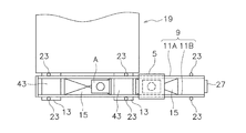
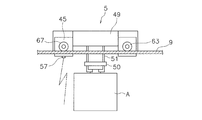
図1~図3を用いて、第1実施形態の搬送システム1を説明する。図1は、第1実施形態の搬送システム1の要部側面図である。図2は、搬送システム1の要部平面図である。図3は、ローカル台車5の側面図である。
搬送システム1は、天井走行車3を有している。天井走行車3は、例えば半導体工場内で工程間搬送と工程内搬送とを行う。
(1)搬送システムの全体
図1~図3を用いて、第1実施形態の搬送システム1を説明する。図1は、第1実施形態の搬送システム1の要部側面図である。図2は、搬送システム1の要部平面図である。図3は、ローカル台車5の側面図である。
搬送システム1は、天井走行車3を有している。天井走行車3は、例えば半導体工場内で工程間搬送と工程内搬送とを行う。
搬送システム1は、ローカル台車5を有している。ローカル台車5は、個々の処理装置19に対するFOUP等の物品Aの供給と搬出を行い、あるいは隣接した数台の処理装置19に対する物品Aの供給と搬出を行う。
搬送システム1は、第1軌道7を有している。第1軌道7は、天井走行車3の軌道であり、走行レールと金属レールとを有している。
搬送システム1は、第1軌道7を有している。第1軌道7は、天井走行車3の軌道であり、走行レールと金属レールとを有している。
搬送システム1は、第2軌道9を有している。第2軌道9は、ローカル台車5の軌道であり、図2に示す第1金属レール11A及び第2金属レール11Bからなる。物品Aは、第1金属レール11A及び第2金属レール11B間の隙間を上下に通過できる。ローカル台車5は第2軌道9の上方を走行するが、吊り下げ式で第2軌道9の下方を走行してもよい。
処理装置19は1又は複数個のロードポート13を備える。処理装置19の前面に平行に第1軌道7及び第2軌道9とバッファ15が延びている。
天井17は、クリーンルームなどの天井である。支柱21、23、25により、第1軌道7及び第2軌道9とバッファ15とが支持されている。
処理装置19は1又は複数個のロードポート13を備える。処理装置19の前面に平行に第1軌道7及び第2軌道9とバッファ15が延びている。
天井17は、クリーンルームなどの天井である。支柱21、23、25により、第1軌道7及び第2軌道9とバッファ15とが支持されている。
バッファ15は、物品Aを仮置きし、第2軌道9の下方に、第1軌道7及び第2軌道9と平行に配置されている。バッファ15の高さレベルは、物品Aが仮置きされているバッファ15の上部を、物品Aを搬送しているローカル台車5が通過できるように設定されている。
第1軌道7が最も高い位置にあり、その例えば直下に第2軌道9があり、第1軌道7及び第2軌道9は平行で上下に重なっている。第1軌道7及び第2軌道9の直下にこれらと平行にバッファ15があり、ロードポート13は第1軌道7及び第2軌道9の直下にある。
第1軌道7が最も高い位置にあり、その例えば直下に第2軌道9があり、第1軌道7及び第2軌道9は平行で上下に重なっている。第1軌道7及び第2軌道9の直下にこれらと平行にバッファ15があり、ロードポート13は第1軌道7及び第2軌道9の直下にある。
搬送システム1は、ローカルコントローラ27を有する。ローカルコントローラ27は、ローカル台車5を制御し、光通信などでローカル台車5と通信する。なおローカルコントローラ27は地上側に設けられてもよい。
天井走行車3は、昇降台29と、昇降台29を昇降させるホイスト(図示せず)とを有しており、鉛直方向に沿って物品Aを移載する。天井走行車3は光通信部31を備える。光軸が上下方向を向きかつローカル台車5の走行経路を通過する光での光通信により、光通信部31は、ロードポート13の側に設けた光通信部33との間で物品Aの受け渡し前のインターロックを行う。さらに天井走行車3にはローカルコントローラ27との通信手段(図示せず)を設けられている。当該通信手段は、バッファ15との間で物品Aを受け渡しする際に、ローカルコントローラ27と通信する。
処理装置19は、加工装置、検査装置などである。処理装置19の前面にはロードポート13が設けられている。天井走行車3、ローカル台車5、及び地上を移動する人がロードポート13との間で物品Aを受け渡しする。処理装置19の前面にはロードポート13の他に、ディスプレイ37と操作パネル39などが設けられている。ディスプレイ37と操作パネル39は、処理装置19の稼働状況を監視し、かつ人手で処理装置19を制御できるようにする。
処理装置19は、加工装置、検査装置などである。処理装置19の前面にはロードポート13が設けられている。天井走行車3、ローカル台車5、及び地上を移動する人がロードポート13との間で物品Aを受け渡しする。処理装置19の前面にはロードポート13の他に、ディスプレイ37と操作パネル39などが設けられている。ディスプレイ37と操作パネル39は、処理装置19の稼働状況を監視し、かつ人手で処理装置19を制御できるようにする。
第2軌道9の第1金属レール11Aと第2金属レール11Bとの間の幅は、物品Aの奥行きよりも大きい。物品Aは昇降台29と共に第1金属レール11Aと第2金属レール11Bとの間の隙間を鉛直方向に通過できる。さらにバッファ15では、ロードポート13の上部に隙間43が設けられている。隙間43は、物品Aがバッファ15を鉛直方向に通過できるようにする。あるいはまた、ロードポート13の直上部を外すようにバッファ15が配置される。これらのため、第1軌道7及び第2軌道9とロードポート13とが鉛直方向に重なるように配置されても、天井走行車3はロードポート13及びバッファ15に対して物品Aの受け渡しができる。同様にローカル台車5はバッファ15及びロードポート13に対し、物品Aの受け渡しができる。従って平面視で搬送システム1が占める床面積を最小にできる。
図3を用いて、ローカル台車5の構造を説明する。ローカル台車5は、走行モータ45(走行駆動モータの一例)を有している。ローカル台車5は、第1受電タイヤ63、第2受電タイヤ65、駆動タイヤ67を有しており、第2軌道9上を走行する(後述)。
ローカル台車5は、ホイスト49を有している。ホイスト49は、吊持材51を巻き取りあるいは繰り出すことにより、昇降台50により支持された物品Aを昇降させる。
ローカル台車5は、ホイスト49を有している。ホイスト49は、吊持材51を巻き取りあるいは繰り出すことにより、昇降台50により支持された物品Aを昇降させる。
ローカル台車5は、光通信部57を有している。光通信部57は、天井走行車3の光通信部31と同様にして、ロードポート13の光通信部33との間で、インターロックのための通信を行う。
ローカル台車5は、走行距離が短く、物品の横送り等の機構を備えず、走行ルートの選択、他の台車との干渉の回避などの情報処理機構を備えない簡素なものである。例えば1台のローカル台車5を第2軌道9に沿って走行させ、処理装置19の前面と前面からやや離れた位置との間を、ローカルコントローラ27の制御で往復させる。そして、ローカル台車5は、天井走行車の第1軌道7の直下の第2軌道9を走行するので、追加の床面積を必要としない。また第2軌道9での第1金属レール11A及び第2金属レール11B間の隙間は、物品Aの奥行きよりも大きいので、第2軌道9を鉛直方向に通過するように物品Aを受け渡しできる。
ローカル台車5は、走行距離が短く、物品の横送り等の機構を備えず、走行ルートの選択、他の台車との干渉の回避などの情報処理機構を備えない簡素なものである。例えば1台のローカル台車5を第2軌道9に沿って走行させ、処理装置19の前面と前面からやや離れた位置との間を、ローカルコントローラ27の制御で往復させる。そして、ローカル台車5は、天井走行車の第1軌道7の直下の第2軌道9を走行するので、追加の床面積を必要としない。また第2軌道9での第1金属レール11A及び第2金属レール11B間の隙間は、物品Aの奥行きよりも大きいので、第2軌道9を鉛直方向に通過するように物品Aを受け渡しできる。
本実施形態での天井走行車3とローカル台車5の制御を示す。
天井走行車3は図示しない上位コントローラにより制御される。ローカルコントローラ27は、上位コントローラ及び天井走行車3、ローカル台車5との間で通信する。天井走行車3及びローカル台車5がロードポート13との間で物品Aを受け渡しする場合、光通信部31、33、57を用いてインターロックを行う。
ロードポート13の直上にローカル台車5が存在すると、天井走行車3は、光通信ができずインターロックが成立しない。そこで、ローカル台車5が他の位置へ移動するまで、物品Aの受け渡しを遅らせる。バッファ15と天井走行車3との間の物品Aの受け渡しは、天井走行車3とローカルコントローラ27との間の通信によりインターロックを成立させる。またローカル台車5は、ローカルコントローラ27からの指示により、バッファ15と物品Aを受け渡しする。このときに、受け渡し前のインターロックは行わない。
天井走行車3は図示しない上位コントローラにより制御される。ローカルコントローラ27は、上位コントローラ及び天井走行車3、ローカル台車5との間で通信する。天井走行車3及びローカル台車5がロードポート13との間で物品Aを受け渡しする場合、光通信部31、33、57を用いてインターロックを行う。
ロードポート13の直上にローカル台車5が存在すると、天井走行車3は、光通信ができずインターロックが成立しない。そこで、ローカル台車5が他の位置へ移動するまで、物品Aの受け渡しを遅らせる。バッファ15と天井走行車3との間の物品Aの受け渡しは、天井走行車3とローカルコントローラ27との間の通信によりインターロックを成立させる。またローカル台車5は、ローカルコントローラ27からの指示により、バッファ15と物品Aを受け渡しする。このときに、受け渡し前のインターロックは行わない。
以上の通信により、バッファ15のどの位置にどの物品が所在するかの在庫データが得られ、ローカルコントローラ27が記憶する。バッファ15の物品Aはローカルコントローラ27が管理する。そしてロードポート13とのインターロックは天井走行車3及びローカル台車5との直接通信、あるいはローカルコントローラ27を介しての通信により成立させる。
(2)ローカル台車走行システム
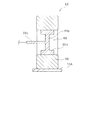
図4~図6を用いて、ローカル台車5並びに第1金属レール11A及び第2金属レール11Bを用いたローカル台車走行システム101(走行体システムの一例)を説明する。図4は、ローカル台車5の模式的平面図である。図5は、ローカル台車5の模式的正面図である。図6は、受電タイヤ63の概略断面図である。
ローカル台車5は、ローカル台車本体61と、第1受電タイヤ63と、第2受電タイヤ65と、駆動タイヤ67とを有している。
図4~図6を用いて、ローカル台車5並びに第1金属レール11A及び第2金属レール11Bを用いたローカル台車走行システム101(走行体システムの一例)を説明する。図4は、ローカル台車5の模式的平面図である。図5は、ローカル台車5の模式的正面図である。図6は、受電タイヤ63の概略断面図である。
ローカル台車5は、ローカル台車本体61と、第1受電タイヤ63と、第2受電タイヤ65と、駆動タイヤ67とを有している。
第1受電タイヤ63(第1の車輪の一例)と第2受電タイヤ65(第2の車輪の一例)は、それぞれ第1金属レール11A及び第2金属レール11B(軌道の一例)に接触して走行するものであり、受電用のタイヤである。
第1受電タイヤ63は、図6に示すように、それぞれ、路面に対する接地部に当たる弾性体層68と、その内部に設けられたタイヤ内導体としてのホイール69(金属の軸体の一例)とを有している。言い換えると、第1受電タイヤ63は、ホイール69の外周面を中実の弾性体層68で被覆したソリッドタイヤである。
弾性体層68は、具体的にはウレタンゴムタイヤである。
ホイール69は、図6に示すように、外周側の円筒部69aと、その内側の円盤部69bと、そこから延びるシャフト69cとを有している。
なお、第2受電タイヤ65の構造は第1受電タイヤ63と同じである。
第1受電タイヤ63は、図6に示すように、それぞれ、路面に対する接地部に当たる弾性体層68と、その内部に設けられたタイヤ内導体としてのホイール69(金属の軸体の一例)とを有している。言い換えると、第1受電タイヤ63は、ホイール69の外周面を中実の弾性体層68で被覆したソリッドタイヤである。
弾性体層68は、具体的にはウレタンゴムタイヤである。
ホイール69は、図6に示すように、外周側の円筒部69aと、その内側の円盤部69bと、そこから延びるシャフト69cとを有している。
なお、第2受電タイヤ65の構造は第1受電タイヤ63と同じである。
第1金属レール11A及び第2金属レール11Bに交流電力が供給されると、第1金属レール11A及び第2金属レール11Bと第1受電タイヤ63及び第2受電タイヤ65とのそれぞれの間で容量結合が発生し、それによりローカル台車5に電力が供給される。具体的には、第1金属レール11A及び第2金属レール11Bに接触することで、第1金属レール11Aと第1受電タイヤ63のホイール69との間に第1コンデンサが形成され、第2金属レール11Bと第2受電タイヤ65のホイール69との間に第2コンデンサが形成される。
弾性体層68は、ウレタンゴムからなる。つまり、弾性体層68は、例えば、ε=6.5~7.1、tanδ=0.015~0.017の範囲にある。この場合、容量結合が強くなり、電力伝送が効率的である。
弾性体層68は、ウレタンゴム以外の材料からなっていてもよい。例えば、塩化ビニル樹脂、ナイロン樹脂、その他樹脂、天然ゴムであってもよい。以下、その場合の好ましい2つの条件を説明する。
第1に、弾性体層68は、空気よりも比誘電率(ε)が高い材料からなることが好ましい。つまり、弾性体層68の比誘電率は1より大きいことが好ましい。この場合、容量結合が強くなり、電力伝送が効率的である。
弾性体層68は、ウレタンゴム以外の材料からなっていてもよい。例えば、塩化ビニル樹脂、ナイロン樹脂、その他樹脂、天然ゴムであってもよい。以下、その場合の好ましい2つの条件を説明する。
第1に、弾性体層68は、空気よりも比誘電率(ε)が高い材料からなることが好ましい。つまり、弾性体層68の比誘電率は1より大きいことが好ましい。この場合、容量結合が強くなり、電力伝送が効率的である。
第2に、弾性体層は、誘電正接(tanδ)が小さい材料からなることが好ましい。この場合、コンデンサ内での電気エネルギー損失が少なくなる。
第1受電タイヤ63及び第2受電タイヤ65のホイール69のシャフト69cは、各々、図4及び図5に示すように、絶縁性カバーで被覆された金属製の軸受71によってローカル台車本体61に回転自在に支持されており、さらにシャフト69cに接続された絶縁性の軸73にエンコーダ75が接続されている。
第1受電タイヤ63及び第2受電タイヤ65のホイール69のシャフト69cは、各々、図4及び図5に示すように、絶縁性カバーで被覆された金属製の軸受71によってローカル台車本体61に回転自在に支持されており、さらにシャフト69cに接続された絶縁性の軸73にエンコーダ75が接続されている。
駆動タイヤ67(第3の車輪の一例)は、第1金属レール11Aに接触して走行するものであり、走行駆動力を発生するためのタイヤである。駆動タイヤ67は、各々、図4に示すように、軸受71によってローカル台車本体61に回転自在に支持されている。さらに軸73にブレーキ77、走行モータ45が接続されている。
第1受電タイヤ63及び第2受電タイヤ65がウレタンゴムにカーボン粒子を含有させていないカーボンレスタイヤで、駆動タイヤ67がカーボン粒子をウレタンゴムに含有させたカーボンタイヤである。この場合、第1受電タイヤ63と第2受電タイヤ65はカーボンを含まないので、誘電正接(tanδ)が小さくなり、その結果、コンデンサ内での電気エネルギー損失が少なくなる。一方、駆動タイヤ67はローカル台車本体61から第1金属レール11Aに静電気を逃がす帯電防止機能を実現している。
第1受電タイヤ63及び第2受電タイヤ65がウレタンゴムにカーボン粒子を含有させていないカーボンレスタイヤで、駆動タイヤ67がカーボン粒子をウレタンゴムに含有させたカーボンタイヤである。この場合、第1受電タイヤ63と第2受電タイヤ65はカーボンを含まないので、誘電正接(tanδ)が小さくなり、その結果、コンデンサ内での電気エネルギー損失が少なくなる。一方、駆動タイヤ67はローカル台車本体61から第1金属レール11Aに静電気を逃がす帯電防止機能を実現している。
図5に示すように、第1金属レール11A及び第2金属レール11Bは互いに対向した状態で平行にレイアウトされた断面L字状である。第1金属レール11A及び第2金属レール11Bは、水平な走行面を有する走行部105と、そこから上方に延びる鉛直壁107とを有している。鉛直壁107の上端同士は連結プレート109によって連結されている。上記に述べた第1金属レール11A、第2金属レール11B及び連結プレート109によって、枠体軌道103が構成されている。なお、図1~3では、簡略化のため、枠体軌道103の全体は表現されていない。
連結プレート109は、絶縁体からなる。つまり、第1金属レール11A及び第2金属レール11Bが互いに絶縁されている。連結プレート109は、第1金属レール11A及び第2金属レール11Bの鉛直壁107の上面を覆っている。このように連結プレート109が第1金属レール11A及び第2金属レール11Bの上側に配置されて第1金属レール11A及び第2金属レール11Bの上方を覆っているので、作業員は、第1金属レール11A及び第2金属レール11Bには触れにくい。したがって、作業者が感電する可能性が低い。
なお、連結プレート109は、走行方向全体にわたって設けられている必要はない。連結プレート109は、部分的に1箇所又は複数箇所に設けられていてもよい。
なお、連結プレート109は、鉛直壁107の上部に加えて鉛直壁107の側方の一部又は全部を覆っていてもよい。
なお、連結プレート109は、走行方向全体にわたって設けられている必要はない。連結プレート109は、部分的に1箇所又は複数箇所に設けられていてもよい。
なお、連結プレート109は、鉛直壁107の上部に加えて鉛直壁107の側方の一部又は全部を覆っていてもよい。
ローカル台車走行システム101は、車両に給電するための電圧印加装置81を有している。電圧印加装置81は、第1金属レール11A及び第2金属レール11Bに接続されており、第1金属レール11A及び第2金属レール11Bに交流電圧を印加する。なお、交流電圧は、矩形波を含む。
電圧印加装置81は、信号発生器83と、バラン85と、整合回路87とを有している。バラン85は、5GHzまでの高周波信号を伝達できる。整合回路87は、インピーダンス整合を取る。その整合された交流電力が、第1金属レール11A及び第2金属レール11Bに供給される。なお、電圧印加装置の構成は特に限定されない。
電圧印加装置81は、信号発生器83と、バラン85と、整合回路87とを有している。バラン85は、5GHzまでの高周波信号を伝達できる。整合回路87は、インピーダンス整合を取る。その整合された交流電力が、第1金属レール11A及び第2金属レール11Bに供給される。なお、電圧印加装置の構成は特に限定されない。
ローカル台車5は、受電装置91を有している。受電装置91は、第1コンデンサ及び第2コンデンサから交流電力をホイール69経由で取り出し、取り出した交流電力を整流し直接的に又はバッテリを介して間接的に、走行モータ45に供給する。
受電装置91は、整合回路93と、整流回路95とを有している。整合回路93は、インピーダンス整合を行う。整流回路95は、受信した交流電力を直流に整流する。第1受電タイヤ63及び第2受電タイヤ65のホイール69は、整合回路93に接続され、整流回路95は走行モータ45に接続されている。なお、受電装置の構成は特に限定されない。
受電装置91は、整合回路93と、整流回路95とを有している。整合回路93は、インピーダンス整合を行う。整流回路95は、受信した交流電力を直流に整流する。第1受電タイヤ63及び第2受電タイヤ65のホイール69は、整合回路93に接続され、整流回路95は走行モータ45に接続されている。なお、受電装置の構成は特に限定されない。
上記の実施形態では、以下の作用効果が得られる。
第1に、第1受電タイヤ63及び第2受電タイヤ65を介在させる電力伝送であるので、効率の良い電力伝送が実現できる。
第2に、ローカル台車走行システム101では、給電に用いられる第1受電タイヤ63及び第2受電タイヤ65をホイール69の外周面を中実の弾性体層68で被覆したソリッドタイヤとしたことで、空気層の介在が無くなるので、容量結合が強くなり、電力伝送が効率的である。
第1に、第1受電タイヤ63及び第2受電タイヤ65を介在させる電力伝送であるので、効率の良い電力伝送が実現できる。
第2に、ローカル台車走行システム101では、給電に用いられる第1受電タイヤ63及び第2受電タイヤ65をホイール69の外周面を中実の弾性体層68で被覆したソリッドタイヤとしたことで、空気層の介在が無くなるので、容量結合が強くなり、電力伝送が効率的である。
さらに、ローカル台車5において、フレキシブル給電線と可撓性の保護カバーを用いた給電構造を廃止できる。これにより、中間移載台車の繰り返し往復走行により給電線断線のおそれがなくなり、保護カバー(ケーブルベア(登録商標))の設置スペースが不要になる。
また、ローカル台車5において、バッテリを廃止することもでき、それによりローカル台車を軽量化できる。この結果、走行駆動源のモータを定格電流の大きなものにする必要がなくなる。
また、ローカル台車5において、バッテリを廃止することもでき、それによりローカル台車を軽量化できる。この結果、走行駆動源のモータを定格電流の大きなものにする必要がなくなる。
2.実施形態の特徴
上記実施形態は下記の様に表現できる。
ローカル台車走行システム101(走行体システムの一例)は、第2軌道9と、電圧印加装置81と、ローカル台車5とを備えている。
第2軌道9(軌道の一例)では、第1金属レール11A及び第2金属レール11Bが互いに平行にレイアウトされている。
電圧印加装置81(電圧印加装置の一例)は、第1金属レール11A及び第2金属レール11Bに交流電圧を印加する。なお、交流電圧は、矩形波を含む。
ローカル台車5(走行体の一例)は、軌道上を走行する。
ローカル台車5は、走行モータ45(走行駆動モータの一例)と、第1受電タイヤ63及び第2受電タイヤ65と、受電装置91とを有している。
第1受電タイヤ63(第1の車輪の一例)及び第2受電タイヤ65(第2の車輪の一例)は、ホイール69(金属の軸体の一例)の外周面を中実の弾性体層68(弾性体層の一例)で被覆したソリッドタイヤからなる。第1受電タイヤ63及び第2受電タイヤ65は、第1金属レール11A及び第2金属レール11Bにそれぞれ接触することで、第1金属レール11Aと第1受電タイヤ63で第1のコンデンサを形成し、第2金属レール11Bと第2受電タイヤ65で第2のコンデンサを形成する。
受電装置91(受電装置の一例)は、第1のコンデンサ及び第2のコンデンサから交流電力をホイール69経由で取り出し、取り出した交流電力を整流し直接的に又は間接的に、走行モータ45に供給する。
上記実施形態は下記の様に表現できる。
ローカル台車走行システム101(走行体システムの一例)は、第2軌道9と、電圧印加装置81と、ローカル台車5とを備えている。
第2軌道9(軌道の一例)では、第1金属レール11A及び第2金属レール11Bが互いに平行にレイアウトされている。
電圧印加装置81(電圧印加装置の一例)は、第1金属レール11A及び第2金属レール11Bに交流電圧を印加する。なお、交流電圧は、矩形波を含む。
ローカル台車5(走行体の一例)は、軌道上を走行する。
ローカル台車5は、走行モータ45(走行駆動モータの一例)と、第1受電タイヤ63及び第2受電タイヤ65と、受電装置91とを有している。
第1受電タイヤ63(第1の車輪の一例)及び第2受電タイヤ65(第2の車輪の一例)は、ホイール69(金属の軸体の一例)の外周面を中実の弾性体層68(弾性体層の一例)で被覆したソリッドタイヤからなる。第1受電タイヤ63及び第2受電タイヤ65は、第1金属レール11A及び第2金属レール11Bにそれぞれ接触することで、第1金属レール11Aと第1受電タイヤ63で第1のコンデンサを形成し、第2金属レール11Bと第2受電タイヤ65で第2のコンデンサを形成する。
受電装置91(受電装置の一例)は、第1のコンデンサ及び第2のコンデンサから交流電力をホイール69経由で取り出し、取り出した交流電力を整流し直接的に又は間接的に、走行モータ45に供給する。
3.他の実施形態
以上、本発明の複数の実施形態について説明したが、本発明は上記実施形態に限定されるものではなく、発明の要旨を逸脱しない範囲で種々の変更が可能である。特に、本明細書に書かれた複数の実施形態及び変形例は必要に応じて任意に組み合せ可能である。
受電タイヤは一対ではなく複数対あってもよい。
連結プレートは導体であってもよい。
以上、本発明の複数の実施形態について説明したが、本発明は上記実施形態に限定されるものではなく、発明の要旨を逸脱しない範囲で種々の変更が可能である。特に、本明細書に書かれた複数の実施形態及び変形例は必要に応じて任意に組み合せ可能である。
受電タイヤは一対ではなく複数対あってもよい。
連結プレートは導体であってもよい。
実施形態の走行体システムは、一例として、半導体搬送や一般物流などのマテリアルハンドリングシステム(MHS)分野に適用することが好ましい。走行台車は凸凹しない軌道を走行するため、車輪は中実のソリッドタイヤを使用しても問題がないからである。しかし、実施形態の走行体システムは、上記分野以外の分野にも広く適用可能である。
実施形態の走行システムは、特に所定の直線範囲を往復する装置に好ましく、例えば、レシプロ式台車、旋盤のローダに適用可能である。
実施形態の走行システムは、特に所定の直線範囲を往復する装置に好ましく、例えば、レシプロ式台車、旋盤のローダに適用可能である。
本発明は、金属レールと車輪との間のコンデンサから交流電力を取り出して走行モータを駆動する走行体システムに広く適用できる。
1 :搬送システム
3 :天井走行車
5 :ローカル台車
7 :第1軌道
9 :第2軌道
11A :第1金属レール
11B :第2金属レール
13 :ロードポート
15 :バッファ
17 :天井
19 :処理装置
21 :支柱
23 :支柱
25 :支柱
27 :ローカルコントローラ
29 :昇降台
31 :光通信部
33 :光通信部
37 :ディスプレイ
39 :操作パネル
43 :隙間
45 :走行モータ
49 :ホイスト
50 :昇降台
51 :吊持材
57 :光通信部
61 :ローカル台車本体
63 :第1受電タイヤ
65 :第2受電タイヤ
67 :駆動タイヤ
68 :弾性体層
69 :ホイール
71 :軸受
73 :軸
75 :エンコーダ
77 :ブレーキ
81 :電圧印加装置
83 :信号発生器
85 :バラン
87 :整合回路
91 :受電装置
93 :整合回路
95 :整流回路
101 :ローカル台車走行システム
A :物品
3 :天井走行車
5 :ローカル台車
7 :第1軌道
9 :第2軌道
11A :第1金属レール
11B :第2金属レール
13 :ロードポート
15 :バッファ
17 :天井
19 :処理装置
21 :支柱
23 :支柱
25 :支柱
27 :ローカルコントローラ
29 :昇降台
31 :光通信部
33 :光通信部
37 :ディスプレイ
39 :操作パネル
43 :隙間
45 :走行モータ
49 :ホイスト
50 :昇降台
51 :吊持材
57 :光通信部
61 :ローカル台車本体
63 :第1受電タイヤ
65 :第2受電タイヤ
67 :駆動タイヤ
68 :弾性体層
69 :ホイール
71 :軸受
73 :軸
75 :エンコーダ
77 :ブレーキ
81 :電圧印加装置
83 :信号発生器
85 :バラン
87 :整合回路
91 :受電装置
93 :整合回路
95 :整流回路
101 :ローカル台車走行システム
A :物品
Claims (7)
- 第1の金属レール及び第2の金属レールを互いに平行にレイアウトした軌道と、
前記第1の金属レール及び前記第2の金属レールに交流電圧を印加する電圧印加装置と、
前記軌道上を走行する走行体と、を備え、
前記走行体は、
走行駆動モータと、
金属の軸体の外周面を中実の弾性体層で被覆したソリッドタイヤからなる第1の車輪及び第2の車輪であって、前記第1の金属レール及び前記第2の金属レールに接触することで、前記第1の金属レールと前記第1の車輪で第1のコンデンサを形成し、前記第2の金属レールと前記第2の車輪で第2のコンデンサを形成する、第1の車輪及び第2の車輪と、
前記第1のコンデンサ及び前記第2のコンデンサから交流電力を前記金属の軸体経由で取り出し、取り出した交流電力を整流し直接的に又は間接的に前記走行駆動モータに供給する受電装置と、を含む
走行体システム。 - 前記弾性体層は、空気よりも比誘電率(ε)が高い材料からなる、請求項1に記載の走行体システム。
- 前記弾性体層は、誘電正接(tanδ)が小さい材料からなる、請求項2に記載の走行体システム。
- 前記弾性体層は、ウレタンゴムからなる、請求項2又は3に記載の走行体システム。
- 前記第1の金属レール及び前記第2の金属レールの一方に接触するが給電に用いられない第3の車輪をさらに備え、
前記走行駆動モータは前記第3の車輪に動力を伝達する、請求項1~4のいずれかに記載の走行体システム。 - 前記第3の車輪がカーボン含有タイヤである、請求項5に記載の走行体システム。
- 前記第1の車輪及び前記第2の車輪がカーボンレスタイヤである、請求項5又は6に記載の走行体システム。
Priority Applications (1)
| Application Number | Priority Date | Filing Date | Title |
|---|---|---|---|
| JP2019528413A JP6864191B2 (ja) | 2017-07-06 | 2018-06-01 | 走行体システム |
Applications Claiming Priority (2)
| Application Number | Priority Date | Filing Date | Title |
|---|---|---|---|
| JP2017-132624 | 2017-07-06 | ||
| JP2017132624 | 2017-07-06 |
Publications (1)
| Publication Number | Publication Date |
|---|---|
| WO2019008965A1 true WO2019008965A1 (ja) | 2019-01-10 |
Family
ID=64950885
Family Applications (1)
| Application Number | Title | Priority Date | Filing Date |
|---|---|---|---|
| PCT/JP2018/021196 Ceased WO2019008965A1 (ja) | 2017-07-06 | 2018-06-01 | 走行体システム |
Country Status (3)
| Country | Link |
|---|---|
| JP (1) | JP6864191B2 (ja) |
| TW (1) | TWI765066B (ja) |
| WO (1) | WO2019008965A1 (ja) |
Cited By (3)
| Publication number | Priority date | Publication date | Assignee | Title |
|---|---|---|---|---|
| JP2021082742A (ja) * | 2019-11-20 | 2021-05-27 | 株式会社ディスコ | 搬送車及び搬送システム |
| JP2021082744A (ja) * | 2019-11-20 | 2021-05-27 | 株式会社ディスコ | 搬送路 |
| CN113368511A (zh) * | 2021-07-26 | 2021-09-10 | 河南工程学院 | 一种可调节环道无碳小车 |
Citations (4)
| Publication number | Priority date | Publication date | Assignee | Title |
|---|---|---|---|---|
| JPH0374202A (ja) * | 1989-08-15 | 1991-03-28 | Aichi Tire Kogyo Kk | 静電気中和タイヤ |
| JPH11249736A (ja) * | 1998-02-27 | 1999-09-17 | Ishikawajima Harima Heavy Ind Co Ltd | 無人搬送台車および無人搬送設備 |
| JP2012055103A (ja) * | 2010-09-02 | 2012-03-15 | Murata Machinery Ltd | 走行車システム |
| JP2012175869A (ja) * | 2011-02-23 | 2012-09-10 | Toyota Central R&D Labs Inc | 車両給電装置及び車両給電方法 |
Family Cites Families (2)
| Publication number | Priority date | Publication date | Assignee | Title |
|---|---|---|---|---|
| CN206106994U (zh) * | 2016-08-15 | 2017-04-19 | 广东中天创展球铁有限公司 | 一种安全电压电动平板车系统 |
| CN106347099A (zh) * | 2016-09-28 | 2017-01-25 | 乐视控股(北京)有限公司 | 电动汽车以及电动汽车供电轨道 |
-
2018
- 2018-06-01 JP JP2019528413A patent/JP6864191B2/ja active Active
- 2018-06-01 WO PCT/JP2018/021196 patent/WO2019008965A1/ja not_active Ceased
- 2018-07-05 TW TW107123330A patent/TWI765066B/zh active
Patent Citations (4)
| Publication number | Priority date | Publication date | Assignee | Title |
|---|---|---|---|---|
| JPH0374202A (ja) * | 1989-08-15 | 1991-03-28 | Aichi Tire Kogyo Kk | 静電気中和タイヤ |
| JPH11249736A (ja) * | 1998-02-27 | 1999-09-17 | Ishikawajima Harima Heavy Ind Co Ltd | 無人搬送台車および無人搬送設備 |
| JP2012055103A (ja) * | 2010-09-02 | 2012-03-15 | Murata Machinery Ltd | 走行車システム |
| JP2012175869A (ja) * | 2011-02-23 | 2012-09-10 | Toyota Central R&D Labs Inc | 車両給電装置及び車両給電方法 |
Cited By (5)
| Publication number | Priority date | Publication date | Assignee | Title |
|---|---|---|---|---|
| JP2021082742A (ja) * | 2019-11-20 | 2021-05-27 | 株式会社ディスコ | 搬送車及び搬送システム |
| JP2021082744A (ja) * | 2019-11-20 | 2021-05-27 | 株式会社ディスコ | 搬送路 |
| JP7408234B2 (ja) | 2019-11-20 | 2024-01-05 | 株式会社ディスコ | 搬送車及び搬送システム |
| JP7471743B2 (ja) | 2019-11-20 | 2024-04-22 | 株式会社ディスコ | 搬送路 |
| CN113368511A (zh) * | 2021-07-26 | 2021-09-10 | 河南工程学院 | 一种可调节环道无碳小车 |
Also Published As
| Publication number | Publication date |
|---|---|
| JP6864191B2 (ja) | 2021-04-28 |
| JPWO2019008965A1 (ja) | 2020-04-23 |
| TW201906749A (zh) | 2019-02-16 |
| TWI765066B (zh) | 2022-05-21 |
Similar Documents
| Publication | Publication Date | Title |
|---|---|---|
| JP6864192B2 (ja) | 走行体システム | |
| US11939198B2 (en) | Transporting system for transporting a container, and method for operating a production installation having a transporting system | |
| JP5382470B2 (ja) | 搬送システム及び搬送方法 | |
| CN1097005C (zh) | 包括输送车辆的轨道导向的输送系统 | |
| JP6864191B2 (ja) | 走行体システム | |
| US10236727B2 (en) | Wireless power transfer system and vehicle power supply device | |
| CN105035673A (zh) | 一种联体双层交叉带式分拣机 | |
| CN1180335A (zh) | 带有能量和信息传输装置的有轨运输装置 | |
| KR102398345B1 (ko) | 반송대차 | |
| WO2014038707A1 (ja) | 車両給電装置 | |
| KR20130108400A (ko) | 반송 시스템 및 반송 방법 | |
| CN104782017B (zh) | 车辆供电装置 | |
| WO2009119791A1 (ja) | クレーン給電システムおよび方法 | |
| US20170008406A1 (en) | Wireless power transfer system and vehicle power supply device | |
| CN203698281U (zh) | 一种运输小车 | |
| JP5729415B2 (ja) | 搬送システム及び搬送方法 | |
| JP2004217409A (ja) | 搬送装置 | |
| CN223921007U (zh) | 一种用于轨道行驶的搬运装置 | |
| JP6280404B2 (ja) | 非接触給電システムと車両給電装置 | |
| KR200489854Y1 (ko) | 반송장치 운반기의 주행 경보 장치 | |
| JP3353541B2 (ja) | 仕分け設備 | |
| KR200341917Y1 (ko) | 대차의 비접촉식 전원공급장치 | |
| JPH10234143A (ja) | 搬送車の非接触給電装置 | |
| JP2606944Y2 (ja) | 給電式自走台車の床装置 | |
| CN203699231U (zh) | 一种轨道运输系统 |
Legal Events
| Date | Code | Title | Description |
|---|---|---|---|
| 121 | Ep: the epo has been informed by wipo that ep was designated in this application |
Ref document number: 18828022 Country of ref document: EP Kind code of ref document: A1 |
|
| ENP | Entry into the national phase |
Ref document number: 2019528413 Country of ref document: JP Kind code of ref document: A |
|
| NENP | Non-entry into the national phase |
Ref country code: DE |
|
| 122 | Ep: pct application non-entry in european phase |
Ref document number: 18828022 Country of ref document: EP Kind code of ref document: A1 |