WO2019003602A1 - 衝突推定装置および衝突推定方法 - Google Patents
衝突推定装置および衝突推定方法 Download PDFInfo
- Publication number
- WO2019003602A1 WO2019003602A1 PCT/JP2018/016245 JP2018016245W WO2019003602A1 WO 2019003602 A1 WO2019003602 A1 WO 2019003602A1 JP 2018016245 W JP2018016245 W JP 2018016245W WO 2019003602 A1 WO2019003602 A1 WO 2019003602A1
- Authority
- WO
- WIPO (PCT)
- Prior art keywords
- moving object
- vehicle
- collision
- trajectory
- extraction area
- Prior art date
- Legal status (The legal status is an assumption and is not a legal conclusion. Google has not performed a legal analysis and makes no representation as to the accuracy of the status listed.)
- Ceased
Links
Images


Classifications
-
- B—PERFORMING OPERATIONS; TRANSPORTING
- B60—VEHICLES IN GENERAL
- B60R—VEHICLES, VEHICLE FITTINGS, OR VEHICLE PARTS, NOT OTHERWISE PROVIDED FOR
- B60R21/00—Arrangements or fittings on vehicles for protecting or preventing injuries to occupants or pedestrians in case of accidents or other traffic risks
- B60R21/01—Electrical circuits for triggering passive safety arrangements, e.g. airbags, safety belt tighteners, in case of vehicle accidents or impending vehicle accidents
- B60R21/013—Electrical circuits for triggering passive safety arrangements, e.g. airbags, safety belt tighteners, in case of vehicle accidents or impending vehicle accidents including means for detecting collisions, impending collisions or roll-over
- B60R21/0134—Electrical circuits for triggering passive safety arrangements, e.g. airbags, safety belt tighteners, in case of vehicle accidents or impending vehicle accidents including means for detecting collisions, impending collisions or roll-over responsive to imminent contact with an obstacle, e.g. using radar systems
-
- B—PERFORMING OPERATIONS; TRANSPORTING
- B60—VEHICLES IN GENERAL
- B60W—CONJOINT CONTROL OF VEHICLE SUB-UNITS OF DIFFERENT TYPE OR DIFFERENT FUNCTION; CONTROL SYSTEMS SPECIALLY ADAPTED FOR HYBRID VEHICLES; ROAD VEHICLE DRIVE CONTROL SYSTEMS FOR PURPOSES NOT RELATED TO THE CONTROL OF A PARTICULAR SUB-UNIT
- B60W30/00—Purposes of road vehicle drive control systems not related to the control of a particular sub-unit, e.g. of systems using conjoint control of vehicle sub-units
- B60W30/08—Active safety systems predicting or avoiding probable or impending collision or attempting to minimise its consequences
- B60W30/095—Predicting travel path or likelihood of collision
Definitions
- the present disclosure relates to the estimation of a collision between a vehicle and a moving object different from the vehicle.
- the movement trajectory of the moving object is estimated, and the collision possibility between the own vehicle and the moving object Various methods for estimating have been proposed.
- the movement trajectory of the moving object can be estimated more accurately by measuring the position of the moving object by taking a longer time using a camera or a millimeter wave radar, and the estimation accuracy of the collision possibility is It can improve.
- the response operation such as an alarm output may be delayed.
- Patent Document 1 when a pedestrian is found in a region set in the vicinity of a stopping vehicle which is a shielding object, the collision estimation can be performed in a shorter time by relaxing a reference condition used for collision estimation (collision determination) Methods are disclosed. Further, as relaxation of the reference condition, for example, it is disclosed that the number of images (the number of frames) used when obtaining the trajectory of a moving object is reduced as compared with other cases.
- Patent No. 5729416 gazette
- the collision is estimated when a pedestrian is recognized within a predetermined area even if the trajectory of the vehicle is away from the moving object because the vehicle is steered.
- the standard conditions used for will be relaxed.
- the reference condition is unnecessarily relaxed despite the relatively long time delay until the countermeasure operation for collision avoidance is performed, and the accuracy of the collision estimation is reduced needlessly . Therefore, there is a need for a technology that can complete the collision estimation early according to the situation while suppressing the decrease in the collision estimation accuracy.
- the present disclosure has been made to solve at least a part of the problems described above, and can be implemented as the following modes.
- a collision estimation device which is mounted on a vehicle and estimates a collision between the moving object different from the vehicle and the vehicle.
- the collision estimation device estimates a trajectory of the moving object based on information obtained in time series from a first trajectory sensor that estimates the trajectory of the vehicle; and a first sensor used to recognize the moving object.
- Moving object trajectory estimation unit an obstacle identification unit identifying the position and size of an obstacle present on the vehicle in the traveling direction side of the vehicle; and the position and size of the identified obstacle Moving object extraction area setting unit for setting a moving object extraction area using the position and size of the shield as a basis;
- Direction change information acquisition for acquiring direction change information indicating a change in the traveling direction of the vehicle Using the unit, the estimated trajectory of the vehicle, the estimated trajectory of the moving object, and the acquired direction change information to estimate the presence or absence of a collision between the vehicle and the moving object Collision estimation unit; and
- the collision estimation unit is configured to move the moving object when the moving object is recognized in the moving object extraction area and the change in the traveling direction indicated by the acquired direction change information is not a direction away from the shielding object;
- the collision is performed using the trajectory of the moving object estimated based on the information obtained from the first sensor in a shorter time than when the moving object is recognized in a region different from the object extraction region.
- the trajectory of the moving object estimated based on the information obtained from the first sensor at the same time or longer time than when the moving object is recognized in a region different from the moving object extraction region And use, to infer the presence or absence of the collision.
- the moving object extraction is performed.
- the presence or absence of a collision is estimated using the trajectory of the moving object estimated based on the information obtained from the first sensor in a shorter time. Because of this, it is possible in a short time even if there is relatively little time delay before executing the response action for collision avoidance, such as “moving objects appear from behind the shield and move toward the trajectory of the vehicle”. Collision estimation can be completed.
- the movement is performed in an area different from the moving object extraction area Since the vehicle's presence or absence is estimated using the trajectory of the moving object estimated based on the information obtained from the first sensor at the same time or longer than that when the object is recognized, the vehicle In the situation where the possibility of a collision with a moving object is low away from the shielding object, it is possible to suppress a decrease in collision estimation accuracy. As described above, according to the collision estimation device of the above embodiment, it is possible to complete the collision estimation early according to the situation while suppressing the decrease in the collision estimation accuracy.
- the present disclosure can also be implemented in various forms other than the collision estimation device.
- it can be realized in the form of a collision estimation method, a computer program for realizing such a method, a storage medium storing such a computer program, a vehicle equipped with a collision estimation device, and the like.
- FIG. 1 is a block diagram showing the configuration of a collision estimation apparatus according to an embodiment of the present disclosure
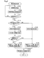
- FIG. 2 is a flowchart showing the procedure of the collision estimation process
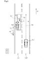
- FIG. 3 is an explanatory view showing an example of the collision estimation process
- FIG. 4 is an explanatory view showing a setting example of a moving object extraction area
- FIG. 5 is an explanatory view showing an example of the collision estimation process
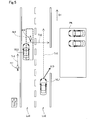
- FIG. 6 is an explanatory view showing a setting example of the moving object extraction area.
- “moving objects different from vehicles” means movable objects or creatures such as pedestrians, bicycles, motorcycles, and unmanned vehicles.
- a vehicle on which the collision estimation device 10 is mounted may be referred to as a "own vehicle”.
- the collision estimation device 10 is configured by an ECU (Electronic Control Unit) equipped with a microcomputer and a memory.
- ECU Electronic Control Unit
- the collision estimation device 10 is electrically connected to various devices mounted on the vehicle, and exchanges data with the various devices. Specifically, as shown in FIG. 1, the collision estimation device 10 includes the millimeter wave radar 21, the imaging device 22, the yaw rate sensor 23, the steering angle sensor 24, the vehicle speed sensor 25, the brake ECU 201, and the alarm ECU 202, respectively. It is connected to to exchange data.
- the millimeter wave radar 21 uses radio waves in the millimeter wave band to detect the presence or absence of an object on the traveling direction side of the vehicle (forward when the vehicle is moving forward), the distance from the object to the vehicle, the object The position of the object, the size of the object, the shape of the object and the relative velocity of the object to the vehicle are detected.
- the “object” detected by the millimeter wave radar 21 is more accurately a set of a plurality of detection points (targets).
- the millimeter wave radar 21 When the ignition of the host vehicle is turned on, the millimeter wave radar 21 repeatedly executes irradiation of millimeter wave radio waves and reception of its reflected wave, and detection of an object (target).
- the imaging device 22 is configured of an imaging camera provided with a lens for collecting light and a light receiving element, and images the traveling direction side of the host vehicle to obtain a captured image.
- the imaging device 22 When the ignition of the host vehicle is turned on, the imaging device 22 repeatedly executes acquisition of a captured image (frame image). For example, an image of 30 frames is acquired per second.
- the frame rate at the time of imaging is not limited to 30 frames per second, and may be an arbitrary value.
- the yaw rate sensor 23 detects the yaw rate (rotational angular velocity) of the host vehicle.
- the yaw rate sensor 23 repeatedly executes detection of the yaw rate when the ignition of the host vehicle is turned on.
- the steering angle sensor 24 detects the steering wheel steering angle of the host vehicle.
- the steering angle sensor 24 repeatedly executes the detection of the steering angle when the ignition of the host vehicle is turned on.
- the vehicle speed sensor 25 detects the speed of the host vehicle.
- the vehicle speed sensor 25 repeatedly executes the detection of the speed of the host vehicle when the ignition of the host vehicle is turned on.
- the brake ECU 201 is an ECU for brake control, and is electrically connected to the collision estimation device 10 and the brake mechanism 211.
- the brake ECU 201 determines the timing to apply the brake and the amount of braking (the amount of braking) and controls the brake mechanism 211.
- the brake mechanism 211 is composed of a sensor, a motor, a valve, a pump, various actuators, and the like involved in the brake control.
- the alarm ECU 202 is an ECU for alarm output, and is electrically connected to the collision estimation device 10 and the alarm mechanism 212.
- the alarm ECU 202 determines the timing of outputting an alarm and the content of the output, and controls the alarm mechanism 212. In the present embodiment, the alarm is output as a sound for alerting a collision with a moving object.
- the alarm mechanism 212 is a device related to audio output such as a speaker and an amplifier.
- the brake ECU 201 and the alarm ECU 202 control the brake mechanism 211 and the alarm mechanism 212, respectively, to cope with collision avoidance. Execute the action. Specifically, an automatic brake is applied and an alarm is issued.
- the collision estimation device 10 includes a vehicle trajectory estimation unit 11, a moving object trajectory estimation unit 12, a shielding object identification unit 13, a moving object extraction area setting unit 14, a direction change information acquisition unit 15, and a collision estimation unit 16. Is equipped. These functional units 11 to 16 are realized by the microcomputer of the collision estimation device 10 executing a control program stored in advance in the collision estimation device 10.
- the vehicle locus estimation unit 11 estimates the locus of the host vehicle based on values obtained periodically in time series from the yaw rate sensor 23, the steering angle sensor 24, and the vehicle speed sensor 25. Specifically, the yaw rate, steering angle, and vehicle speed, which are obtained periodically, are stored as a history, and the planned passing position and the planned passing time of the vehicle are estimated as the trajectory of the vehicle based on the history of a predetermined period. Do.
- the moving object trajectory estimation unit 12 generates a moving object trajectory based on values periodically obtained from the millimeter wave radar 21 in time series and values obtained periodically from the imaging device 22 (frame image data). Estimate the trajectory. Specifically, by combining the position and distance of each target obtained from the millimeter wave radar 21 and the image data obtained from the imaging device 22, the type, position, size, moving direction, and moving speed of the moving object are obtained. presume. Then, the estimated passing position of the moving object and the estimated passing time are estimated as the trajectory of the moving object.
- the type of moving object may be estimated, for example, by pattern matching based on the shape in the frame image.
- the obstacle identification unit 13 identifies the position and the size of the obstacle located on the traveling direction side with respect to the host vehicle.
- the shield is an object that may block moving objects from the millimeter wave radar 21 and the imaging device 22, and means, for example, a non-moving object such as a stopped or parked vehicle, a telephone pole, or a signboard.
- the above-mentioned "do not move” may also include a state of moving at a low speed (forward or backward), in addition to the stopped state. For example, a vehicle that moves at a speed of less than 20 km per hour in the same direction as the traveling direction of the host vehicle is also an object that does not move and corresponds to a shield. Only the stopped state may mean "do not move".
- the shield identification unit 13 determines the position of the shield based on values periodically obtained from the millimeter wave radar 21 in time series and values periodically obtained from the imaging device 22 (frame image data). And identify the size.
- the moving object extraction area setting unit 14 sets a moving object extraction area based on the position and the size of the shielding object using the position and the size of the shielding object specified by the shielding object specifying unit 13.
- the moving object extraction region is a trajectory of a moving object used when estimating a collision with the vehicle under a predetermined condition when a moving object is recognized (extracted) in such a region, and a region different from such a region
- the trajectory estimated based on the values of the millimeter wave radar 21 and the imaging device 22 obtained in a shorter time than when a moving object is recognized in is used in the region. Details of the moving object extraction area will be described later.
- the direction change information acquisition unit 15 acquires direction change information indicating a change in the traveling direction of the host vehicle.
- the direction change information means a change in the steering wheel steering angle obtained from the steering angle sensor 24.
- the traveling direction of the host vehicle changes.
- the collision estimation unit 16 includes the trajectory of the host vehicle estimated by the vehicle trajectory estimation unit 11, the trajectory of the moving object estimated by the moving object trajectory estimation unit 12, and the direction change information obtained by the direction change information acquisition unit 15. That is, the steering angle is used to estimate the presence or absence of a collision between the host vehicle and the automatic body.
- the collision estimation apparatus 10 having the above configuration can complete the collision estimation early according to the situation while suppressing a decrease in the collision estimation accuracy between the own vehicle and the moving object by executing a collision estimation process described later.
- the above-mentioned millimeter wave radar 21 and imaging device 22 correspond to a subordinate concept of the first sensor in the means for solving the problem. Further, the steering angle sensor 24 corresponds to a subordinate concept of the second sensor in the means for solving the problem. Further, the imaging device 22 corresponds to a subordinate concept of the imaging unit in the means for solving the problem.
- Collision estimation process The collision estimation process shown in FIG. 2 is executed in the collision estimation device 10 when the ignition of the host vehicle is turned on.
- the obstacle specifying unit 13 specifies the position and the size of the shield located on the traveling direction side with respect to the host vehicle (step S100).
- the shield specifying unit 13 specifies the vehicle VL2 as a shield and specifies its position and size.
- the moving object extraction area setting unit 14 sets a moving object extraction area based on the position and the size of the shielding specified in step S100 (step S105). In the example of FIG. 3, the moving object extraction area Ar1 is set.
- the moving object extraction area Ar1 is a trajectory of the vehicle along the orthogonal direction from the center P1 along the orthogonal direction orthogonal to the traveling direction D1 at the front end surface S1 of the vehicle VL2 which is a shield.
- a side from a point P11 separated by a first distance L1 determined in advance to a side closer to the locus Tr0 shown in FIG. 3 is one side, and is previously determined from the rear end P2 of the vehicle VL2 along the traveling direction D1 from the center P1 described above. It is set as a rectangular area in a plan view with one side up to a point P3 separated by the second distance L2.
- the first distance L1 may be, for example, 1.5 m (meters).
- the second distance L2 may be, for example, 5.0 m.
- the values of the first distance L1 and the second distance L2 are not limited to these values, and may be set to arbitrary values.
- the rear end P2 means the end of the targets of the vehicle VL2 obtained by the millimeter wave radar 21 that is determined based on the target on the farthest side along the traveling direction D1. Therefore, the actual rear end of the vehicle VL2 (the deepest point along the traveling direction D1) may not be set as the rear end P2.
- the moving object extraction area Ar1 set as described above is an area in the vicinity of the vehicle VL2, and when the moving object jumps out from an area (dead spot) blocked by the vehicle VL2 when viewed from the vehicle VL1. This is an area in which there is relatively little time delay until the response operation for collision avoidance is performed.
- a person m2 as a moving object is present in the moving object extraction area Ar1.
- the moving object trajectory estimation unit 12 determines whether there is a moving object on the traveling direction side (step S110). When it is determined that there is no moving object on the traveling direction side (step S110: NO), the process returns to step S100 described above.
- step S110 when it is determined that there is a moving object on the traveling direction side (step S110: YES), the moving object trajectory estimation unit 12 determines whether the moving object exists in the moving object extraction area or not. It determines (step S115). In the example of FIG. 3, the moving object trajectory estimation unit 12 recognizes the person m1 as a moving object on the sidewalk next to the first lane Ln1, and recognizes the person m2 as a moving object in the moving object extraction area Ar1. Do. Therefore, in step S110, it is determined that there are a plurality of moving objects (two persons m1 and m2) on the traveling direction D1 side. In such a case, the process from step S115 is executed for each moving object.
- the moving object person m1 is not present in the moving object extraction area Ar1. In this case, it is determined that the moving object does not exist in the moving object extraction area (step S115: NO), and the vehicle trajectory estimation unit 11 estimates the trajectory of the own vehicle (step S120).
- a locus in which the host vehicle travels straight in the second lane Ln2 currently being traveled is estimated as the locus Tr0 of the host vehicle.
- the moving object trajectory estimation unit 12 calculates the image data of the standard number of frames and the measurement result of the millimeter wave radar 21 obtained in the period corresponding to the period when the image data of the number of frames is obtained.
- the trajectory of the moving object is estimated (step S125).
- the standard number of frames is five.
- the number of frames is not limited to five and may be an arbitrary number of frames.
- a trajectory Tr1 of a person m1 as a moving object is estimated.
- the collision estimation unit 16 determines the presence or absence of a collision between the own vehicle and the moving object based on the trajectory of the own vehicle estimated in step S120 and the moving object trajectory estimated in step S125. It estimates (step S130). In the example of FIG. 3, the locus Tr0 of the vehicle VL1 and the locus Tr1 of the person m1 as a moving object do not intersect. Therefore, for the person m1, it is determined that "no collision has occurred". After execution of step S130, the process returns to step S100 described above.
- step S115 since the person m2 exists in the moving object extraction area Ar1, it is determined that "the moving object exists in the moving object extraction area" (step S115: YES). In this case, the vehicle trajectory estimation unit 11 estimates the trajectory of the host vehicle (step S135). Since this step S135 is the same as step S120 described above, the detailed description will be omitted. If the trajectory of the host vehicle has already been estimated in the processing for another moving object (for example, step S120), step S135 may be omitted using the estimation result. Similarly, also in step S120 described above, if the trajectory of the host vehicle has already been estimated in the processing for another moving object (for example, step S135), step S120 is omitted using the estimation result. You may
- step S140 the direction change information acquisition unit 15 acquires direction change information (step S140).
- the information that there is no change in the steering wheel steering angle, that is, "there is no change in the traveling direction of the host vehicle" is obtained.
- the direction change information acquiring unit 15 determines whether the change in the traveling direction of the host vehicle is a change in the direction away from the shield (step S145). As in the example of FIG. 3, when it is determined that there is no change in the steering angle, it is determined that the change in the direction away from the shield is not (step S145: NO). In this case, the moving object trajectory estimation unit 12 moves the moving object based on the image data of the reduced frame number and the measurement result of the millimeter wave radar 21 obtained in the period corresponding to the period when the image data of the frame number is obtained. The trajectory of is estimated (step S150).
- the reduced number of frames means the number of frames smaller than the “standard number of frames” in step S125 described above, and is “3 frames” in the present embodiment.
- the number of frames is not limited to three, and may be an arbitrary number of frames smaller than the standard number of frames.
- step S150 unlike in step S125 described above, movement is performed based on the image data of the reduced frame number and the measurement result of the millimeter wave radar 21 obtained in the period according to the period in which the image data of the frame number is obtained. Since the trajectory of the object is estimated, the time required to estimate the trajectory of the moving object is shorter than in step S125.
- step S130 After execution of step S150, the above-mentioned step S130 is performed.
- the collision estimation device 10 when it is determined that "collision occurrence", the collision estimation device 10 notifies the brake ECU 201 and the alarm ECU 202 of "collision occurrence" and information on the collision position, and based on the information, The corresponding action for collision avoidance described above is performed.
- step S145 If it is determined in step S145 described above that the change in the traveling direction of the host vehicle is a change in the direction away from the shield (step S145: YES), the above-described step S125 is performed. That is, the trajectory of the moving object is estimated based on the image data of the standard number of frames and the measurement result of the millimeter wave radar 21 obtained in the period according to the period when the image data of the number of frames is obtained.
- step S140 information indicating a change ⁇ D in the direction of turning to the right is acquired as the change in the traveling direction of the host vehicle. Therefore, in step S145, the direction change information acquiring unit 15 determines that the change in the traveling direction of the vehicle VL1 is a direction away from the vehicle VL2 which is a shielding object (step S145: YES).
- the trajectory of the moving object is based on the image data of the standard number of frames and the measurement result of the millimeter wave radar 21 obtained in the period corresponding to the period when the image data of such number of frames is obtained.
- the locus Tr0 estimated as the locus of the vehicle VL1 is a locus that goes straight on in the second lane Ln2, but the change in the direction in which the traveling direction turns to the right Because of the change in direction, the possibility of collision with the person m2 is low.
- the time margin is relatively large for the execution of the response operation for collision avoidance. Therefore, in such a case, the collision estimation device 10 is configured to improve the estimation accuracy of the trajectory of the moving object by using frame image data of the standard number of frames.
- the moving object (person m2) is recognized in the moving object extraction area Ar1, and the change in the traveling direction indicated by the acquired direction change information is a shield If it is not in the direction away from (vehicle VL2), the first sensor (millimeter wave radar 21 and the milliwave radar 21 and in a shorter time than when the moving object (person m1) is recognized in the area different from the moving object extraction area Ar1.
- the moving object Since the occurrence of a collision is estimated using the trajectory Tr2 of the moving object (person m2) estimated based on the information obtained from the imaging device 22), the moving object (from the shadow of the shielding object (vehicle VL2) It is possible to complete the collision estimation in a short time even in a situation where there is relatively little time delay before performing the response operation for collision avoidance such as the appearance of the person m2 and movement toward the trajectory Tr0 of the vehicle. .
- the moving object (person m2) is recognized in the moving object extraction area Ar1
- the change ⁇ D in the traveling direction indicated by the acquired direction change information is a direction away from the shielding object (vehicle VL2)
- the possibility of a collision with a moving object (person m2) is reduced since the vehicle VL1 is separated from the shielding object by using the trajectory of the moving object (person m2) to estimate the presence or absence of a collision occurrence.
- the collision estimation device 10 of the first embodiment the collision estimation can be completed early according to the situation while suppressing the decrease in the collision estimation accuracy.
- a side from a point P11 separated by L1 is taken as one side
- a side from a center P1 to a point P3 taken a predetermined second distance L2 from the rear end P2 of the shielding object (vehicle VL2) along the traveling direction D1
- the direction change information acquisition unit 15 acquires direction change information based on the value obtained from the steering angle sensor 24, that is, the steering wheel steering angle of the host vehicle, so that the change in the traveling direction D1 of the vehicle VL1 is a shield ( It can be accurately specified whether the vehicle is in the direction away from the vehicle VL2).
- the moving object extraction area Ar1 is set based on the position and the size of the vehicle VL2 which is one shielding object, but the present disclosure is not limited thereto.
- a moving object extraction area may be set based on the positions and sizes of a plurality of shields. Specifically, for example, as shown in FIG. 6, a vehicle VL3 stopped at a distance ⁇ L away from the vehicle VL2 along the traveling direction D1 with the above-described vehicle VL2 is recognized as a shield.
- the moving object extraction area Ar2 may be set as follows.
- the orthogonal direction Of the plurality of shields (two vehicles VL2 and VL3) from the center P1 with one side to a point P21 separated by a predetermined third distance L3 on the side approaching the trajectory Tr0 of the vehicle VL1 along the A rectangular area with one side from the rear end P12 of the innermost shield (vehicle VL3) to a point P13 separated by a predetermined fourth distance L4 along the traveling direction D1 is a moving object extraction area Ar2 It may be set.
- the third distance L3 may be, for example, 1.5 m as in the above-described first distance L1.
- the fourth distance L4 may be, for example, 5.0 m as in the above-described second distance L2.
- the values of the third distance L3 and the fourth distance L4 are not limited to these values, and may be set to arbitrary values.
- the position and shape of the moving object extraction area in the present disclosure are not limited to the position and shape of the moving object extraction area Ar1 of the first embodiment described above.
- the end point on the front side end face (end face S1) of the shielding object on the side closest to the trajectory Tr0 of the vehicle (vehicle VL1) is taken as a vertex, and a rectangular area having a side parallel to the traveling direction D1 is moved It may be an object extraction area.
- a point at a predetermined distance in the direction orthogonal to the traveling direction D1 from the end point closest to the trajectory Tr0 of the own vehicle (vehicle VL1) in the front end face of the shield is taken as a vertex and parallel to the traveling direction D1.
- a rectangular area having a side may be used as a moving object extraction area. Further, for example, a virtual line parallel to the traveling direction D1 passing through the center along the orthogonal direction orthogonal to the traveling direction D1 at the front end face of the shielding object, and the shielding object on the side closer to the locus Tr0 of the own vehicle (vehicle VL1)
- a circular area having a predetermined radius centered on an intersection of a traveling direction D1 passing through the center along the traveling direction D1 of the side face and a virtual line orthogonal to the traveling direction D1 may be used as a moving object extraction area.
- the moving object extraction regions in these examples can all be set using the position and size of the shield. That is, in general, an area based on the position and size of the shield may be set as the moving object extraction area based on the position and size of the shield.
- the direction change information means the change of the steering wheel steering angle obtained from the steering angle sensor 24, but the present disclosure is not limited to this.
- it may mean a change in tire steering angle obtained from a not-shown tire steering angle sensor mounted on the host vehicle.
- it may mean a change in the yaw rate obtained from the yaw rate sensor 23.
- it may mean information indicating the operating state of the direction indication device (turn indicator) mounted on the host vehicle.
- the operation state of the turn indicator is an operation state indicating a right turn
- the direction change information indicates that the change in the traveling direction of the host vehicle is on the right.
- the direction change information indicates that the change in the traveling direction of the host vehicle is on the left side.
- a vehicle includes map information for a navigation device (not shown)
- it may mean information obtained by specifying the type of a road on which the vehicle travels based on the map information.
- the type of the road on which the vehicle travels is based on the map information is a left turn lane
- it indicates that the change in the traveling direction of the vehicle is on the left side.
- it may mean the type of sign painted on the road in the captured image obtained by the imaging device 22.
- the type of sign painted on the road in the captured image is a sign indicating a left turn, it indicates that the change in the traveling direction of the host vehicle is on the left side.
- the vehicle locus estimation unit 11 estimates the locus of the host vehicle based on values periodically obtained from the yaw rate sensor 23, the steering angle sensor 24, and the vehicle speed sensor 25.
- the present disclosure is not limited thereto.
- the trajectory of the host vehicle may be estimated based on the history of the position information of the host vehicle obtained chronologically by the GPS device.
- the moving object trajectory estimation unit 12 is based on the value periodically obtained from the millimeter wave radar 21 and the value periodically obtained from the imaging device 22 (frame image data),
- the trajectory of the moving object has been estimated, the present disclosure is not limited thereto.
- the trajectory of a moving object may be estimated based on only values periodically obtained from the millimeter wave radar 21.
- the millimeter wave radar 21 corresponds to a subordinate concept of the first sensor in the means for solving the problem.
- the trajectory of the moving object may be estimated based on only values (frame image data) periodically obtained from the imaging device 22.
- the imaging device 22 corresponds to a subordinate concept of the first sensor in the means for solving the problem.
- step S145 when the change in the traveling direction of the host vehicle is a change in the direction away from the shield (step S145: YES), the recognized moving object is different from the moving object extraction region Similarly, the trajectory of a moving object has been estimated based on a frame image of a standard number of frames, but the present disclosure is not limited thereto. If the change in the traveling direction of the host vehicle is a change in the direction away from the shield, the trajectory of the moving object may be estimated based on frame images of a number of frames greater than the standard number of frames. When the change in the traveling direction of the host vehicle is a change in the direction away from the shield, the possibility of collision with a moving object is lower than in the case where the traveling direction of the host vehicle does not change. Therefore, in such a case, the trajectory of the moving object can be estimated more accurately by estimating the trajectory of the moving object based on the frame image of a larger number of frames.
- each sensor 21, 23-25 and imaging device 22 of a 1st embodiment detected a value regularly, if a value is obtained chronologically, even if it detects irregularly Good.
- a part of the configuration implemented by hardware may be replaced by software, and conversely, a part of the configuration implemented by software may be replaced by hardware
- the “computer-readable recording medium” is not limited to portable recording media such as flexible disks and CD-ROMs, but is fixed to internal storage devices in computers such as various RAMs and ROMs, and computers such as hard disks. Also includes an external storage device. That is, "computer-readable recording medium” has a broad meaning including any recording medium that can fix data packets, not temporarily.
- the present disclosure is not limited to the above-described embodiments, and can be implemented with various configurations without departing from the scope of the present disclosure.
- the technical features in the embodiments corresponding to the technical features in the modes described in the section of the summary of the invention can be used to solve some or all of the problems described above, or the effects of the effects described above. Replacements and combinations can be made as appropriate to achieve part or all. Also, if the technical features are not described as essential in the present specification, they can be deleted as appropriate.
Landscapes
- Engineering & Computer Science (AREA)
- Mechanical Engineering (AREA)
- Automation & Control Theory (AREA)
- Transportation (AREA)
- Radar, Positioning & Navigation (AREA)
- Remote Sensing (AREA)
- Traffic Control Systems (AREA)
- Control Of Driving Devices And Active Controlling Of Vehicle (AREA)
Applications Claiming Priority (2)
| Application Number | Priority Date | Filing Date | Title |
|---|---|---|---|
| JP2017127189A JP6690604B2 (ja) | 2017-06-29 | 2017-06-29 | 衝突推定装置および衝突推定方法 |
| JP2017-127189 | 2017-06-29 |
Publications (1)
| Publication Number | Publication Date |
|---|---|
| WO2019003602A1 true WO2019003602A1 (ja) | 2019-01-03 |
Family
ID=64742878
Family Applications (1)
| Application Number | Title | Priority Date | Filing Date |
|---|---|---|---|
| PCT/JP2018/016245 Ceased WO2019003602A1 (ja) | 2017-06-29 | 2018-04-20 | 衝突推定装置および衝突推定方法 |
Country Status (2)
| Country | Link |
|---|---|
| JP (1) | JP6690604B2 (enExample) |
| WO (1) | WO2019003602A1 (enExample) |
Cited By (4)
| Publication number | Priority date | Publication date | Assignee | Title |
|---|---|---|---|---|
| CN113140194A (zh) * | 2020-01-17 | 2021-07-20 | 北京小米移动软件有限公司 | 亮度调节方法、装置及存储介质 |
| CN113147747A (zh) * | 2020-01-06 | 2021-07-23 | 株式会社万都 | 用于辅助车辆驾驶的设备及其方法 |
| CN113859251A (zh) * | 2021-10-29 | 2021-12-31 | 广州文远知行科技有限公司 | 涉及行驶盲区的车速规划方法、驾驶控制方法及相关设备 |
| CN116489593A (zh) * | 2022-01-24 | 2023-07-25 | 本田技研工业株式会社 | 信息处理装置、移动体、系统、信息处理方法和计算机可读存储介质 |
Citations (5)
| Publication number | Priority date | Publication date | Assignee | Title |
|---|---|---|---|---|
| JP2004310315A (ja) * | 2003-04-04 | 2004-11-04 | Nissan Motor Co Ltd | 情報提供装置、情報提供システムおよび情報提供用プログラム |
| JP2007083817A (ja) * | 2005-09-21 | 2007-04-05 | Honda Motor Co Ltd | 運転支援装置 |
| JP2014213776A (ja) * | 2013-04-26 | 2014-11-17 | 株式会社デンソー | 衝突判定装置、および衝突緩和装置 |
| WO2016159297A1 (ja) * | 2015-03-31 | 2016-10-06 | 株式会社デンソー | 安全装置作動タイミング制御方法および装置 |
| JP2016192165A (ja) * | 2015-03-31 | 2016-11-10 | 株式会社デンソー | 運転支援装置、及び運転支援方法 |
-
2017
- 2017-06-29 JP JP2017127189A patent/JP6690604B2/ja active Active
-
2018
- 2018-04-20 WO PCT/JP2018/016245 patent/WO2019003602A1/ja not_active Ceased
Patent Citations (5)
| Publication number | Priority date | Publication date | Assignee | Title |
|---|---|---|---|---|
| JP2004310315A (ja) * | 2003-04-04 | 2004-11-04 | Nissan Motor Co Ltd | 情報提供装置、情報提供システムおよび情報提供用プログラム |
| JP2007083817A (ja) * | 2005-09-21 | 2007-04-05 | Honda Motor Co Ltd | 運転支援装置 |
| JP2014213776A (ja) * | 2013-04-26 | 2014-11-17 | 株式会社デンソー | 衝突判定装置、および衝突緩和装置 |
| WO2016159297A1 (ja) * | 2015-03-31 | 2016-10-06 | 株式会社デンソー | 安全装置作動タイミング制御方法および装置 |
| JP2016192165A (ja) * | 2015-03-31 | 2016-11-10 | 株式会社デンソー | 運転支援装置、及び運転支援方法 |
Cited By (7)
| Publication number | Priority date | Publication date | Assignee | Title |
|---|---|---|---|---|
| CN113147747A (zh) * | 2020-01-06 | 2021-07-23 | 株式会社万都 | 用于辅助车辆驾驶的设备及其方法 |
| CN113147747B (zh) * | 2020-01-06 | 2024-05-31 | 汉拿科锐动电子股份公司 | 用于辅助车辆驾驶的设备及其方法 |
| CN113140194A (zh) * | 2020-01-17 | 2021-07-20 | 北京小米移动软件有限公司 | 亮度调节方法、装置及存储介质 |
| CN113140194B (zh) * | 2020-01-17 | 2023-08-29 | 北京小米移动软件有限公司 | 亮度调节方法、装置及存储介质 |
| CN113859251A (zh) * | 2021-10-29 | 2021-12-31 | 广州文远知行科技有限公司 | 涉及行驶盲区的车速规划方法、驾驶控制方法及相关设备 |
| CN116489593A (zh) * | 2022-01-24 | 2023-07-25 | 本田技研工业株式会社 | 信息处理装置、移动体、系统、信息处理方法和计算机可读存储介质 |
| US12406582B2 (en) | 2022-01-24 | 2025-09-02 | Honda Motor Co., Ltd. | Information processing apparatus, moving object, system, information processing method, and computer-readable storage medium |
Also Published As
| Publication number | Publication date |
|---|---|
| JP2019010911A (ja) | 2019-01-24 |
| JP6690604B2 (ja) | 2020-04-28 |
Similar Documents
| Publication | Publication Date | Title |
|---|---|---|
| JP6747389B2 (ja) | 衝突推定装置および衝突推定方法 | |
| US11097724B2 (en) | Apparatus and system for controlling travel of vehicle | |
| JP7119428B2 (ja) | 運転支援装置 | |
| JP6828428B2 (ja) | 車両用衝突回避支援装置および車両の衝突回避支援方法 | |
| JP6190758B2 (ja) | 物体認識装置及び車両 | |
| CN109891262B (zh) | 物体探测装置 | |
| JP4684954B2 (ja) | 車両の走行安全装置 | |
| EP3608635A1 (en) | Positioning system | |
| US20180356527A1 (en) | Method for assisting a driver of a vehicle/trailer combination in maneuvering with the vehicle/trailer combination, blind spot system as well as vehicle/trailer combination | |
| US10255814B2 (en) | Driving assistance apparatus | |
| WO2017014080A1 (ja) | 運転支援システム | |
| JP5785578B2 (ja) | 車両周辺監視装置 | |
| US20160090085A1 (en) | Drive Assist Apparatus of Vehicle and Onboard Computer | |
| WO2016194851A1 (ja) | 物体検出装置および物体検出方法 | |
| WO2019003602A1 (ja) | 衝突推定装置および衝突推定方法 | |
| JP2017010498A (ja) | 車両制御装置 | |
| WO2019012921A1 (ja) | 車両における制動支援装置および制動支援制御方法 | |
| CN107408346A (zh) | 车辆控制装置以及车辆控制方法 | |
| US7057502B2 (en) | Vehicle drive assist apparatus | |
| CN112542060A (zh) | 车用后侧方警报装置 | |
| JP2019010911A5 (enExample) | ||
| US11444921B2 (en) | Vehicular firewall providing device | |
| CN110065492B (zh) | 车辆控制系统 | |
| JP7181956B2 (ja) | 移動体の制御装置及び制御方法並びに車両 | |
| JP7685114B2 (ja) | 周辺監視装置、プログラム及び周辺監視方法 |
Legal Events
| Date | Code | Title | Description |
|---|---|---|---|
| 121 | Ep: the epo has been informed by wipo that ep was designated in this application |
Ref document number: 18824012 Country of ref document: EP Kind code of ref document: A1 |
|
| NENP | Non-entry into the national phase |
Ref country code: DE |
|
| 122 | Ep: pct application non-entry in european phase |
Ref document number: 18824012 Country of ref document: EP Kind code of ref document: A1 |