WO2019003503A1 - 位相差フィルム、円偏光板、および位相差フィルムの製造方法 - Google Patents
位相差フィルム、円偏光板、および位相差フィルムの製造方法 Download PDFInfo
- Publication number
- WO2019003503A1 WO2019003503A1 PCT/JP2018/009158 JP2018009158W WO2019003503A1 WO 2019003503 A1 WO2019003503 A1 WO 2019003503A1 JP 2018009158 W JP2018009158 W JP 2018009158W WO 2019003503 A1 WO2019003503 A1 WO 2019003503A1
- Authority
- WO
- WIPO (PCT)
- Prior art keywords
- retardation
- film
- heating
- stretched film
- polarizing plate
- Prior art date
- Legal status (The legal status is an assumption and is not a legal conclusion. Google has not performed a legal analysis and makes no representation as to the accuracy of the status listed.)
- Ceased
Links
Images

Classifications
-
- B—PERFORMING OPERATIONS; TRANSPORTING
- B29—WORKING OF PLASTICS; WORKING OF SUBSTANCES IN A PLASTIC STATE IN GENERAL
- B29C—SHAPING OR JOINING OF PLASTICS; SHAPING OF MATERIAL IN A PLASTIC STATE, NOT OTHERWISE PROVIDED FOR; AFTER-TREATMENT OF THE SHAPED PRODUCTS, e.g. REPAIRING
- B29C55/00—Shaping by stretching, e.g. drawing through a die; Apparatus therefor
- B29C55/02—Shaping by stretching, e.g. drawing through a die; Apparatus therefor of plates or sheets
- B29C55/04—Shaping by stretching, e.g. drawing through a die; Apparatus therefor of plates or sheets uniaxial, e.g. oblique
- B29C55/06—Shaping by stretching, e.g. drawing through a die; Apparatus therefor of plates or sheets uniaxial, e.g. oblique parallel with the direction of feed
-
- B—PERFORMING OPERATIONS; TRANSPORTING
- B29—WORKING OF PLASTICS; WORKING OF SUBSTANCES IN A PLASTIC STATE IN GENERAL
- B29C—SHAPING OR JOINING OF PLASTICS; SHAPING OF MATERIAL IN A PLASTIC STATE, NOT OTHERWISE PROVIDED FOR; AFTER-TREATMENT OF THE SHAPED PRODUCTS, e.g. REPAIRING
- B29C55/00—Shaping by stretching, e.g. drawing through a die; Apparatus therefor
- B29C55/02—Shaping by stretching, e.g. drawing through a die; Apparatus therefor of plates or sheets
- B29C55/04—Shaping by stretching, e.g. drawing through a die; Apparatus therefor of plates or sheets uniaxial, e.g. oblique
- B29C55/08—Shaping by stretching, e.g. drawing through a die; Apparatus therefor of plates or sheets uniaxial, e.g. oblique transverse to the direction of feed
-
- G—PHYSICS
- G02—OPTICS
- G02B—OPTICAL ELEMENTS, SYSTEMS OR APPARATUS
- G02B5/00—Optical elements other than lenses
- G02B5/30—Polarising elements
-
- H—ELECTRICITY
- H05—ELECTRIC TECHNIQUES NOT OTHERWISE PROVIDED FOR
- H05B—ELECTRIC HEATING; ELECTRIC LIGHT SOURCES NOT OTHERWISE PROVIDED FOR; CIRCUIT ARRANGEMENTS FOR ELECTRIC LIGHT SOURCES, IN GENERAL
- H05B33/00—Electroluminescent light sources
- H05B33/02—Details
Definitions
- the present invention relates to a retardation film, a circularly polarizing plate, and a method for producing a retardation film.
- the organic EL panel has a highly reflective metal layer, and easily causes problems such as reflection of external light and reflection of a background. Therefore, it is known to prevent these problems by providing a circularly polarizing plate having a ⁇ / 4 plate on the viewing side.
- the retardation film used for the said circularly-polarizing plate usually differs in retardation value with wavelengths, and a sufficient antireflection effect is not obtained with a wavelength, but color loss becomes a problem. Therefore, a so-called reverse dispersion retardation film has been proposed, in which the retardation value increases as the wavelength increases (for example, Patent Document 1).
- the above-mentioned conventional reverse dispersive retardation film may change in retardation value when used in a high temperature environment and / or a high humidity environment, resulting in retardation unevenness. There is a case.
- the present invention has been made to solve the above-mentioned conventional problems, and the main object thereof is a retardation film in which a change in retardation value in a high temperature and high humidity environment is suppressed, such a retardation film It is providing a circularly-polarizing plate which it has, and the manufacturing method of such retardation film.
- the method for producing a retardation film of the present invention is a method for producing a retardation film in which the in-plane retardation satisfies the relationship Re (450) ⁇ Re (550), and the temperature is raised from 30 ° C. to Tg-25 ° C.
- the shrinkage in the slow axis direction is 0.4% or less in the heating TMA test repeating 3 cycles of cooling again to 30 ° C., or 25 ° C./25% RH, 85 ° C./2% RH,
- the above includes the heat treatment step of heating.
- the heating temperature in the heat treatment step is T 1 (° C.), and the heating time in the heat treatment step is t 1 (minutes), and the above-mentioned stretched film before the heat treatment step is Assuming that the contraction rate in the heating TMA test is A 1 , 10 ⁇ t 1 / ⁇ (Tg ⁇ T 1 ) 2 ⁇ A 1 2 ⁇ > 2 is satisfied.
- the heating temperature in the heat treatment step is T 1 (° C.), and the heating time in the heat treatment step is t 1 (minutes), and the above-mentioned stretched film before the heat treatment step is Assuming that the contraction rate in the humidified TMA test is A 2 , 10 ⁇ t 1 / ⁇ (Tg ⁇ T 1 ) 2 ⁇ A 2 2 ⁇ > 0.9 is satisfied.
- the method for producing a retardation film of the present invention is a method for producing a retardation film in which the in-plane retardation satisfies the relationship of Re (450) ⁇ Re (550), wherein 25 ° C./25% RH, 85 ° C.
- a stretched film having a shrinkage in the slow axis direction of 0.7% or less It includes a warm water treatment step of immersing in warm water for 3 minutes or more.
- the immersion time in the hot water treatment step t 2 and (minutes), when the shrinkage ratio in the humidifying TMA test the hot water treatment step prior to the stretched film was A 3, t 2 / A 3 2 > 20 is satisfied.
- a retardation film is provided.
- This retardation film satisfies the relationship of in-plane retardation Re (450) ⁇ Re (550), and is heated up from 30 ° C to Tg-25 ° C and cooled again to 30 ° C.
- the shrinkage ratio in the slow axis direction is 0.1% or less, and the environment is in the order of 25 ° C / 25% RH, 85 ° C / 2% RH, 85 ° C / 85% RH, 85 ° C / 2% RH.
- the shrinkage factor in the slow axis direction is 0.2% or less in the humidified TMA test in which In one embodiment, the retardation film is formed of a resin selected from a polycarbonate resin and a polyester carbonate resin.
- the retardation film has a Re (450) / Re (550) of 0.8 to 0.9. In one embodiment, the retardation film has a photoelastic coefficient of 1 ⁇ 10 ⁇ 12 (m 2 / N) to 40 ⁇ 10 ⁇ 12 (m 2 / N).
- a circularly polarizing plate is provided. This circularly polarizing plate has a retardation layer composed of the above retardation film and a polarizer, and the angle between the slow axis of the retardation layer and the absorption axis of the polarizer is 35 ° to 55 °.
- the circularly polarizing plate is sheet-like, and the in-plane retardation value of the central portion of the retardation layer is R A0, and the in-plane retardation value of the apex portion is R B0. after holding by bonding glass 240 hours at 85 ° C., the in-plane retardation value of the center portion of the retardation layer as R A1, an in-plane retardation value of the apex portion and R B1, glass on both sides And the in-plane retardation value of the central portion of the retardation layer as R A2 and the in-plane retardation value of the apex portion as R B2 after bonding them together and holding them at 65 ° C./90% RH for 240 hours.
- the shrinkage rate in the slow axis direction is 0.4% or less in the heating TMA test, or the shrinkage rate in the slow phase direction is 0.7% or less in the humidified TMA test
- a heat treatment step of heating a certain stretched film at a temperature of 105 ° C. or more for 2 minutes or more a retardation film in which a change in retardation value in a high temperature and high humidity environment is suppressed may be obtained.
- Refractive index (nx, ny, nz) “Nx” is the refractive index in the direction in which the in-plane refractive index is maximum (ie, the slow axis direction), and “ny” is the direction orthogonal to the slow axis in the plane (ie, the fast axis direction) And “nz” is the refractive index in the thickness direction.
- Refractive index (nx, ny, nz) “Nx” is the refractive index in the direction in which the in-plane refractive index is maximum (ie, the slow axis direction), and “ny” is the direction orthogonal to the slow axis in the plane (ie, the fast axis direction) And “nz” is the refractive index in the thickness direction.
- In-plane retardation (Re) “Re ( ⁇ )” is an in-plane retardation measured at 23 ° C. with light of wavelength ⁇ nm.
- Re (550) is an in-plane retardation measured with light of wavelength 550 nm at 23 ° C.
- Retardation in the thickness direction (Rth) is a retardation in the thickness direction measured with light of wavelength ⁇ nm at 23 ° C.
- the production method of the present invention is a production used for production of a retardation film showing so-called reverse dispersion wavelength dependency in which in-plane retardation satisfies the relationship of Re (450) ⁇ Re (550). It is a method.
- the method for producing a retardation film according to one embodiment of the present invention includes a heat treatment step of heating the stretched film at a temperature of 105 ° C. or more for 2 minutes or more.
- the stretched film has a shrinkage in the slow axis direction of 0.4% or less in a heated TMA test which repeats heating and cooling from 30 ° C. to Tg-25 ° C.
- the shrinkage in the slow axis direction is 0.7% It is below.
- the heating temperature in the heat treatment step is T 1 (° C.)
- the heating time in the heat treatment step is t 1 (minutes)
- the contraction rate in the heating TMA test of the stretched film before the heat treatment step is A 1
- 10 ⁇ t 1 / ⁇ (Tg ⁇ T 1 ) 2 ⁇ A 1 2 ⁇ > 2 is satisfied.
- the shrinkage ratio in humidified TMA test of the stretched film before the heat treatment step was set to A 2, preferably, meet the 10 ⁇ t 1 / ⁇ (Tg -T 1) 2 ⁇ A 2 2 ⁇ > 0.9.
- the method for producing a retardation film according to another embodiment of the present invention includes a warm water treatment step of immersing the stretched film in warm water of 60 ° C. or more for 3 minutes or more.
- the stretched film has a shrinkage rate in the slow axis direction in a humidified TMA test in which the environment is changed in the order of 25 ° C./25% RH, 85 ° C./2% RH, 85 ° C./85% RH, 85 ° C./2% RH It is 0.7% or less.
- the immersion time in the warm water treatment process is t 2 (minutes)
- the contraction ratio in the moistened TMA test of the drawn film before the warm water treatment process is A 3 , preferably t 2 / A 3 2 > 20 is satisfied.
- the shrinkage ratio in the slow axis direction is 0.4% or less in the heated TMA test which repeats the cycle of raising the temperature from 30 ° C to Tg-25 ° C and cooling again to 30 ° C as described above.
- a stretched film is typically produced by stretching a resin film in at least one direction.
- the resin film is formed of any appropriate resin as long as a stretched film (retardation film) exhibiting so-called reverse dispersion wavelength dependency can be obtained by subjecting the resin film to a stretching treatment.
- resin which forms a resin film polycarbonate resin, polyvinyl acetal resin, cellulose ester-type resin, polyester-type resin, polyester carbonate-type resin is mentioned, for example. These resins may be used alone or in combination depending on the desired properties.
- any appropriate polycarbonate resin may be used as the polycarbonate resin.
- a polycarbonate resin containing a structural unit derived from a dihydroxy compound is preferable.
- the dihydroxy compound 9,9-bis (4-hydroxyphenyl) fluorene, 9,9-bis (4-hydroxy-3-methylphenyl) fluorene, 9,9-bis (4-hydroxy-3-3) Ethylphenyl) fluorene, 9,9-bis (4-hydroxy-3-n-propylphenyl) fluorene, 9,9-bis (4-hydroxy-3-isopropylphenyl) fluorene, 9,9-bis (4-hydroxy) -3-n-butylphenyl) fluorene, 9,9-bis (4-hydroxy-3-sec-butylphenyl) fluorene, 9,9-bis (4-hydroxy-3-tert-butylphenyl) fluorene, 9, 9-Bis (4-hydroxy-3-cyclohexylphenyl) fluorene, 9,9-Bis
- the polycarbonate resin contains a structural unit derived from a dihydroxy compound such as isosorbide, isomannide, isoidet, spiro glycol, dioxane glycol, diethylene glycol, triethylene glycol, polyethylene glycol, and bisphenols in addition to the structural unit derived from the dihydroxy compound. It may be.
- a dihydroxy compound such as isosorbide, isomannide, isoidet, spiro glycol, dioxane glycol, diethylene glycol, triethylene glycol, polyethylene glycol, and bisphenols in addition to the structural unit derived from the dihydroxy compound. It may be.
- the glass transition temperature (Tg) of the polycarbonate resin is preferably 110 ° C. or more and 250 ° C. or less, more preferably 120 ° C. or more and 230 ° C. or less. If the glass transition temperature is excessively low, the heat resistance tends to deteriorate, and dimensional change may occur after film formation. When the glass transition temperature is excessively high, the molding stability at the time of film molding may be deteriorated, and the transparency of the film may be impaired.
- the glass transition temperature is determined in accordance with JIS K 7121 (1987).
- melt extrusion for example, T-die molding
- cast coating for example, casting
- calendar molding heat pressing
- coextrusion co-melting
- multilayer extrusion inflation molding
- T-die molding casting and inflation molding are used.
- the thickness of the thickness (unstretched film) of the resin film may be set to any appropriate value depending on the desired optical properties, the stretching conditions described later, and the like.
- the thickness is preferably 50 to 300 ⁇ m, and more preferably 80 to 250 ⁇ m.
- any appropriate stretching direction and stretching conditions eg, stretching temperature, stretching ratio, stretching direction
- various stretching methods such as free end stretching, fixed end stretching / free end shrinkage, fixed end shrinkage can be used alone or simultaneously or sequentially.
- the stretching direction can also be performed in various directions and dimensions, such as the horizontal direction, the vertical direction, the thickness direction, and the diagonal direction.
- the stretching temperature is preferably in the range of the glass transition temperature (Tg) of the resin film ⁇ 20 ° C.
- a stretched film is produced by uniaxially stretching or uniaxially stretching a resin film.
- uniaxial stretching there is a method of stretching in the longitudinal direction (longitudinal direction) while traveling the resin film in the longitudinal direction.
- the stretch ratio is preferably 10% to 500%.
- a stretched film is produced by continuously stretching a long resin film obliquely in the direction of the angle ⁇ with respect to the long direction.
- a long stretched film having an orientation angle of angle ⁇ with respect to the longitudinal direction of the film can be obtained, and, for example, roll-to-roll becomes possible upon lamination with a polarizer, and the manufacturing process Can be simplified.
- a tenter type drawing machine capable of applying a feed force or a drawing force or a take-up force at different speeds in the lateral and / or longitudinal directions
- a tenter type stretching machine includes a transverse uniaxial stretching machine, a simultaneous biaxial stretching machine, etc., any appropriate stretching machine may be used as long as it can continuously stretch a long resin film obliquely.
- the thickness of the stretched film is preferably 20 ⁇ m to 100 ⁇ m, more preferably 30 ⁇ m to 80 ⁇ m.
- a commercially available film may be used as it is, or the commercially available film may be subjected to secondary processing (for example, stretching treatment, surface treatment) according to the purpose.
- secondary processing for example, stretching treatment, surface treatment
- a trade name "Pure Ace RM” manufactured by Teijin Limited can be mentioned.
- the stretched film is subjected to a relaxation treatment.
- a relaxation treatment Thereby, the stress generated by stretching can be relaxed, and the contraction rate in the slow axis direction in the heating TMA test is 0.4% or less, or the contraction rate in the slow axis direction in the humidification TMA test is 0. It may be 7% or less.
- Any appropriate condition may be adopted as the relaxation treatment condition.
- the stretched film is shrunk along the stretching direction at a predetermined relaxation temperature and a predetermined relaxation rate (shrinkage ratio).
- the relaxation temperature is preferably 60.degree. C. to 150.degree.
- the relaxation rate is preferably 3% to 6%.
- the stretched film is heated at a temperature of 105 ° C. or more for 2 minutes or more.
- the heating temperature in the heat treatment step is T 1 (° C.), and the heating time in the heat treatment step is t 1 (minutes), and the shrinkage in the heated TMA test of the stretched film before the heat treatment step
- the ratio is A 1 , preferably, the value represented by 10 ⁇ t 1 / ⁇ (Tg ⁇ T 1 ) 2 ⁇ A 1 2 ⁇ is larger than 2.
- the above value is preferably more than 2 and less than 150, more preferably 3 to 50, and particularly preferably 3 to 10.
- (Tg ⁇ T 1 ) is preferably 5 or more.
- the shrinkage ratio in humidified TMA test of the stretched film before the heat treatment step when the A 2 preferably, 10 ⁇ t 1 / ⁇ ( Tg-T 1) 2 ⁇ A 2 2 ⁇
- the represented value is greater than 0.9.
- the above value is preferably 1 to 60, more preferably 1 to 20, and particularly preferably 1 to 10.
- the heating temperature is preferably 105 ° C. to 140 ° C., more preferably 110 ° C. to 130 ° C., particularly preferably 115 ° C. to 125 ° C.
- the heating time is preferably 2 minutes to 150 minutes, more preferably 3 minutes to 120 minutes, and particularly preferably 5 minutes to 60 minutes.
- any appropriate heating means can be used as long as the stretched film can be heated under the above heating conditions.
- the heating means is typically an oven.
- a stretched film is obtained by stretching a long resin film while traveling in the long direction, the obtained stretched film may be subjected to heat treatment while traveling as it is.
- Hot Water Treatment Step In the warm water treatment step, as described above, the stretched film is immersed in warm water of 60 ° C. or more for 3 minutes or more.
- the above value is preferably more than 20 and 1,000 or less, more preferably 25 to 500, and particularly preferably 30 to 150.
- the temperature of the hot water is preferably 60 ° C. to 90 ° C., more preferably 65 ° C. to 85 ° C., particularly preferably 68 ° C. to 82 ° C.
- the immersion time is preferably 3 minutes to 60 minutes, more preferably 3 minutes to 30 minutes, and particularly preferably 5 minutes to 20 minutes.
- any suitable warm water treatment means can be used as long as the stretched film can be heated under the above heating conditions.
- the hot water treatment means is typically a hot water bath adjusted to an appropriate temperature.
- the hot water treatment may be performed while running the obtained stretched film as it is.
- the retardation film of the present invention is a retardation film exhibiting in-plane retardation satisfying the relationship of Re (450) ⁇ Re (550), that is, a retardation film showing so-called reverse dispersion wavelength dependency.
- the retardation film has a shrinkage ratio in the slow axis direction of 0.1% or less in a heated TMA test which repeats heating and cooling from 30 ° C. to Tg-25 ° C. three cycles again.
- the shrinkage in the slow axis direction is 0.2% It is below.
- the shrinkage factor in the slow axis direction in the above-mentioned heated TMA test is preferably 0% to 0.08%, and more preferably 0% to 0.05%.
- the shrinkage factor in the slow axis direction in the humidified TMA test is preferably 0% to 0.15%, and more preferably 0% to 0.10%.
- the retardation film as described above can suppress the change in retardation value in a high temperature and high humidity environment.
- the value of Re (450) / Re (550) of the retardation film is preferably 0.8 to 0.9, and more preferably 0.83 to 0.87.
- the in-plane retardation Re (550) of the retardation film is preferably 100 nm to 180 nm, more preferably 135 nm to 155 nm.
- the photoelastic coefficient of the retardation film is preferably 1 ⁇ 10 ⁇ 12 (m 2 / N) to 40 ⁇ 10 ⁇ 12 (m 2 / N), more preferably 1 ⁇ 10 ⁇ 12 (m 2 / N) And 30 ⁇ 10 ⁇ 12 (m 2 / N), particularly preferably 1 ⁇ 10 ⁇ 12 (m 2 / N) to 20 ⁇ 10 ⁇ 12 (m 2 / N).
- the retardation film as described above can be obtained, for example, by the manufacturing method described in Section A.
- the retardation film may be used for a circularly polarizing plate.
- the circularly polarizing plate of the present invention has a retardation layer composed of the above retardation film, and a polarizer.
- the angle between the slow axis of the retardation layer and the absorption axis of the polarizer is 35 ° to 55 °, preferably 40 ° to 50 °, particularly preferably 43 to 47 °, and most preferably It is about 45 °.
- FIG. 1 is a schematic cross-sectional view of a circularly polarizing plate according to one embodiment of the present invention.
- the circularly polarizing plate 100 is sheet-like.
- the retardation unevenness (heating retardation unevenness) of the retardation layer 30 when the circularly polarizing plate 100 is heated is 3 nm or less.
- the retardation unevenness (humidified retardation unevenness) of the retardation layer 30 when the circularly polarizing plate 100 is humidified is 3 nm or less.
- the heating retardation unevenness and the humidification retardation unevenness are preferably 0 nm to 2 nm, more preferably 0 nm to 1 nm.
- the heating phase difference unevenness can be determined, for example, as an absolute value of a value calculated from the following equation when glass is attached to both sides of the circularly polarizing plate 100 and heated (held at 85 ° C. for 240 hours) .
- R A1 -R B1 is the in-plane retardation value of the central portion of the retardation layer 30
- R B0 is the in-plane retardation value of the top portion of the retardation layer 30
- R A1 is the retardation after the heating.
- the in-plane retardation value of the central portion of the layer 30, R.sub.B1 is the in-plane retardation value of the peak portion after the heating.
- the above-mentioned humidification phase difference unevenness is, for example, as an absolute value of a value calculated from the following equation when glass is attached to both sides of the circularly polarizing plate 100 and humidified (holding for 240 hours at 65 ° C./90% RH) It can be determined.
- R A2 -R B2 is an in-plane retardation value of the central portion of the retardation layer 30 after the humidification
- R B2 is an in-plane retardation value of the apex portion after the humidification.
- the retardation layer is composed of the retardation film
- the change of the in-plane retardation at the end of the retardation layer can be suppressed, and the retardation unevenness is Can be suppressed.
- the resin film forming the polarizer may be a single layer resin film, or may be a laminate of two or more layers.
- the polarizer composed of a single-layer resin film include hydrophilic polymer films such as polyvinyl alcohol (PVA) -based films, partially formalized PVA-based films, ethylene / vinyl acetate copolymer-based partially saponified films, etc.
- PVA polyvinyl alcohol
- those which have been subjected to a dyeing process and a drawing process with a dichroic substance such as iodine and a dichroic dye and a polyene-based oriented film such as a dewatered product of PVA or a dehydrochlorinated product of polyvinyl chloride.
- a polarizer obtained by dyeing a PVA-based film with iodine and uniaxially stretching it is used because of excellent optical properties.
- the staining with iodine is performed, for example, by immersing a PVA-based film in an aqueous iodine solution.
- the stretching ratio of the uniaxial stretching is preferably 3 to 7 times. Stretching may be carried out after the dyeing process or may be carried out while dyeing. Moreover, it may be dyed after being drawn.
- the PVA-based film is subjected to swelling treatment, crosslinking treatment, washing treatment, drying treatment, and the like. For example, by immersing and washing the PVA-based film in water prior to dyeing, it is possible not only to wash the stains and anti-blocking agent on the surface of the PVA-based film, but also to swell the PVA-based film to make uneven dyeing It can be prevented.
- the polarizer obtained by using a laminate a laminate of a resin substrate and a PVA-based resin layer (PVA-based resin film) laminated on the resin substrate, or a resin substrate and the resin
- coated-formed to the base material is mentioned.
- coated and formed by the said resin base material applies a PVA-type resin solution to a resin base material, for example, it is made to dry, and a resin base material Forming a PVA-based resin layer thereon to obtain a laminate of the resin base and the PVA-based resin layer; stretching and dyeing the laminate to make the PVA-based resin layer as a polarizer; obtain.
- stretching typically includes dipping the laminate in a boric acid aqueous solution and stretching.
- stretching may optionally further comprise air-stretching the laminate at a high temperature (eg, 95 ° C. or higher) prior to stretching in an aqueous boric acid solution.
- the resulting laminate of resin substrate / polarizer may be used as it is (that is, the resin substrate may be used as a protective layer of polarizer), and the resin substrate is peeled off from the laminate of resin substrate / polarizer.
- any appropriate protective layer depending on the purpose may be laminated on the peeled surface.
- the details of the method for producing such a polarizer are described, for example, in JP-A-2012-73580. The publication is incorporated herein by reference in its entirety.
- the thickness of the polarizer is, for example, 1 ⁇ m to 80 ⁇ m. In one embodiment, the thickness of the polarizer is preferably 1 ⁇ m to 15 ⁇ m, more preferably 3 ⁇ m to 10 ⁇ m, and particularly preferably 3 ⁇ m to 8 ⁇ m. If the thickness of the polarizer is in such a range, curling at the time of heating can be favorably suppressed, and good appearance durability at the time of heating can be obtained.
- the circularly polarizing plate having such a second retardation layer can suppress changes in reflectance and reflection hue when used in an organic EL panel.
- the thickness direction retardation Rth (550) of the second retardation layer is preferably -50 nm to -300 nm, more preferably -70 nm to -250 nm, still more preferably -90 nm to -200 nm, particularly preferably -100 nm to -180 nm.
- the second retardation layer may preferably include a liquid crystal material fixed in homeotropic alignment.
- the liquid crystal material (liquid crystal compound) which can be homeotropically aligned may be a liquid crystal monomer or a liquid crystal polymer.
- Specific examples of the method of forming the liquid crystal compound and the second retardation layer include the method of forming a liquid crystal compound and a retardation film described in [0020] to [0028] of JP-A-2002-333642.
- the thickness of the second retardation layer is preferably 0.5 ⁇ m to 10 ⁇ m, more preferably 0.5 ⁇ m to 8 ⁇ m, and still more preferably 0.5 ⁇ m to 5 ⁇ m.
- the second retardation layer may be formed of a retardation film formed of fumaric acid diester resin described in JP-A-2012-32784.
- the thickness is preferably 5 ⁇ m to 80 ⁇ m, more preferably 10 ⁇ m to 50 ⁇ m.
- the protective layer is formed of any suitable protective film that can be used as a film to protect a polarizer.
- suitable protective film include cellulose-based resins such as triacetyl cellulose (TAC), polyester-based, polyvinyl alcohol-based, polycarbonate-based, polyamide-based, polyimide-based, polyether sulfone-based, and polysulfone.
- transparent resins such as polystyrene, polynorbornene, polyolefin, (meth) acrylic and acetate.
- thermosetting resins such as (meth) acrylic resins, urethane resins, (meth) acrylic urethane resins, epoxy resins, and silicone resins, ultraviolet curable resins, and the like can also be mentioned.
- glassy polymers such as siloxane polymers can also be mentioned.
- a polymer film described in JP-A-2001-343529 (WO 01/37007) can also be used.
- a resin composition containing a thermoplastic resin having a substituted or unsubstituted imide group in a side chain, and a thermoplastic resin having a substituted or unsubstituted phenyl group and a nitrile group in a side chain for example, a resin composition having an alternating copolymer of isobutene and N-methyl maleimide and an acrylonitrile / styrene copolymer can be mentioned.
- the polymer film may be, for example, an extrusion of the resin composition.
- the thickness of the protective film is preferably 10 ⁇ m to 100 ⁇ m.
- the protective film may be laminated to the polarizer through an adhesive layer (specifically, an adhesive layer, an adhesive layer), or may be laminated to the polarizer in close contact (without the adhesive layer). Good.
- the adhesive layer is formed of any suitable adhesive.
- the water-soluble adhesive which has polyvinyl alcohol-type resin as a main component is mentioned, for example.
- the water-soluble adhesive containing a polyvinyl alcohol-based resin as a main component can preferably further contain a metal compound colloid.
- the metal compound colloid may be one in which metal compound fine particles are dispersed in a dispersion medium, may be electrostatically stabilized due to mutual repulsion of the same kind of charge of the fine particles, and may be permanently stable. .
- the average particle size of the fine particles forming the metal compound colloid may be any appropriate value as long as the optical properties such as polarization properties are not adversely affected.
- the thickness is preferably 1 nm to 100 nm, more preferably 1 nm to 50 nm. This is because fine particles can be uniformly dispersed in the adhesive layer, adhesion can be secured, and knicks can be suppressed. In addition, a "knick" means the thing of the local uneven defect which arises at the interface of a polarizer and a protective film.
- the pressure-sensitive adhesive layer is composed of any suitable pressure-sensitive adhesive.
- the surface of the protective film opposite to the polarizer may be subjected to surface treatment such as hard coating treatment, anti-reflection treatment, anti-sticking treatment, anti-glare treatment, etc., as necessary.
- the thickness of the protective film is typically 5 mm or less, preferably 1 mm or less, more preferably 1 ⁇ m to 500 ⁇ m, and still more preferably 5 ⁇ m to 150 ⁇ m.
- thermomechanical analyzer (Hitachi High-Tech Science Co., Ltd., model number “TMA7100”), increase the temperature of the measurement sample from 30 ° C. to Tg-25 ° C. and cool it again to 30 ° C. for three cycles and measure The dimensional change rate (shrinkage rate) in the longitudinal direction (late axis direction) of the sample was measured. The temperature rising rate was 5 ° C./min, and the holding time at each temperature was 10 minutes.
- (4) Dimensional change due to humidification Huidified TMA test
- the stretched film or retardation film obtained in Examples and Comparative Examples was cut into a size of 20 mm (in slow axis direction) ⁇ 5 mm (in fast axis direction) to obtain a measurement sample.
- the length direction of the measurement sample was measured.
- the holding time at 25 ° C./25% RH was 60 minutes
- the holding time at 85 ° C./2% RH was 60 minutes
- the holding time at 85 ° C./85% RH was 300 minutes.
- phase difference value RB11 and the in-plane phase difference value RB12 of the peak portion located in the fast axis direction from the center portion were measured.
- the larger one of the absolute values of the values A and B obtained from the following equation was regarded as heating phase difference unevenness.
- A (R A1 -R B11 )-(R A0 -R B01 )
- B (R A1- R B12 )-(R A0- R B02 ) (6)
- Humidification phase difference unevenness A measurement sample of a circularly polarizing plate is produced in the same manner as in (5) above, and the in-plane retardation value R A0 of the central portion and the apex portion located in the slow axis direction from the central portion the in-plane retardation value R B01, an in-plane retardation value R B02 vertex portion positioned from the center to the fast axis was measured.
- the measurement sample is humidified in an oven at 65 ° C./90% for 240 hours, and the in-plane retardation value R A2 of the central portion and the apex portion located in the slow axis direction from the central portion
- the in-plane retardation value RB21 and the in-plane retardation value RB22 of the vertex located in the fast axis direction from the central portion were measured.
- the larger one of the absolute values of the values C and D obtained from the following equation was taken as the humidification phase difference unevenness.
- C (R A2- R B21 )-(R A0- R B01 )
- D (R A2- R B22 )-(R A0- R B02 )
- Example 1 Preparation of retardation film (polycarbonate resin) The polymerization was carried out using a batch polymerization apparatus consisting of two vertical reactors equipped with stirring blades and a reflux condenser controlled at 100 ° C. 29.60 parts by mass (0.046 mol) of bis [9- (2-phenoxycarbonylethyl) fluoren-9-yl] methane, 29.21 parts by mass (0.200 mol) of ISB, 42.28 parts by mass of SPG (0. 139 mol), 63.77 parts by mass (0.298 mol) of DPC and 1.19 ⁇ 10 -2 parts by mass (6.78 ⁇ 10 -5 mol) of calcium acetate monohydrate were loaded as a catalyst.
- a batch polymerization apparatus consisting of two vertical reactors equipped with stirring blades and a reflux condenser controlled at 100 ° C. 29.60 parts by mass (0.046 mol) of bis [9- (2-phenoxycarbonylethyl) fluoren-9-yl]
- a resin film having a thickness of 135 ⁇ m was produced using a film production apparatus equipped with a set temperature of 120 to 130 ° C. and a winder.
- a stretched film is obtained by stretching the obtained long resin film in the width direction at a stretching temperature of 134 ° C. and a stretching ratio of 2.8 times and subsequently subjecting the stretched film in the width direction to a relaxation treatment.
- the relaxation treatment conditions were a relaxation temperature of 130 ° C. and a relaxation rate of 4.5%.
- the stretched film was subjected to the humidified TMA test of (4) above, and the dimensional change was 0.30%. Moreover, when this stretched film was subjected to the heating TMA test of the above (3), the dimensional change was 0.05%. Next, the stretched film was heated (heat treatment) at 125 ° C. for 2 minutes to obtain a retardation film with a thickness of 48 ⁇ m.
- a long amorphous polyethylene terephthalate (A-PET) film (Mitsubishi Resins Co., Ltd., trade name "Novaclear", thickness: 100 ⁇ m) is prepared as a substrate, and polyvinyl alcohol (PVA) resin is formed on one side of the substrate.
- PVA polyvinyl alcohol
- An aqueous solution of (Gosenol (registered trademark) NH-26, trade name, manufactured by Japan Synthetic Chemical Industry Co., Ltd.) was applied and dried at 60 ° C. to form a 7 ⁇ m-thick PVA-based resin layer.
- the laminate thus obtained was immersed in an insolubilization bath at a liquid temperature of 30 ° C.
- a side chain type liquid crystal polymer represented by the following chemical formula (I)
- 80 parts by weight of a polymerizable liquid crystal manufactured by BASF: trade name Paliocolor LC 242
- a photopolymerization initiator manufactured by BASF: trade name Irgacure 907
- 5 parts by weight was dissolved in 400 parts by weight of cyclopentanone to prepare a liquid crystal coating liquid.
- the coating solution is applied to a base film (a norbornene resin film: manufactured by Nippon Zeon Co., Ltd., trade name "Zeonor") by a bar coater, and then the liquid crystal is dried by heating and drying at 70 ° C for 4 minutes. It was oriented.
- the liquid crystal layer was irradiated with ultraviolet light to cure the liquid crystal layer, whereby a liquid crystal solidified layer (thickness: 1 ⁇ m) to be a retardation film was formed on the substrate.
- the Re (550) of this layer was 0 nm, and the Rth (550) was -71 nm (nx: 1.5326, ny: 1.5326, nz: 1.6550).
- the retardation film was bonded to the polarizer side of the polarizing plate via an adhesive such that the angle between the absorption axis of the polarizer and the slow axis of the retardation film was 45 °. Subsequently, the said liquid-crystal solidified layer is transcribe
- the circularly-polarizing plate which has the structure of a protective layer / polarizer / retardation layer / 2nd retardation layer Made.
- Example 2 A retardation film and a circularly polarizing plate were produced in the same manner as in Example 1 except that the stretched film was heated at 125 ° C. for 10 minutes.
- Example 3 A retardation film and a circularly polarizing plate were produced in the same manner as in Example 1 except that the stretched film was heated at 125 ° C. for 30 minutes.
- Example 4 A retardation film and a circularly polarizing plate were produced in the same manner as in Example 1 except that the stretched film was heated at 125 ° C. for 60 minutes.
- Example 5 A retardation film and a circularly polarizing plate were produced in the same manner as in Example 1 except that the stretched film was heated at 125 ° C. for 120 minutes.
- Example 6 A stretched film was produced in the same manner as in Example 1 except that the relaxation temperature was 110 ° C. The stretched film was subjected to the humidified TMA test in (4) above, and the dimensional change was 0.50%. Moreover, when this stretched film was subjected to the heating TMA test of the above (3), the dimensional change was 0.08%. A retardation film and a circularly polarizing plate were produced in the same manner as in Example 2 except that the above-mentioned stretched film was used.
- Example 7 A stretched film was produced in the same manner as in Example 1 except that the relaxation temperature was 80 ° C. The stretched film was subjected to the humidified TMA test in (4) above, and the dimensional change was 0.70%. Moreover, when this stretched film was subjected to the heating TMA test of the above (3), the dimensional change was 0.13%. A retardation film and a circularly polarizing plate were produced in the same manner as in Example 2 except that the above-mentioned stretched film was used.
- Example 8 A retardation film and a circularly polarizing plate were produced in the same manner as in Example 1 except that the stretched film was heated at 105 ° C. for 10 minutes.
- Example 9 A retardation film and a circularly polarizing plate were produced in the same manner as in Example 1 except that the stretched film was heated at 110 ° C. for 10 minutes.
- Example 10 A retardation film and a circularly polarizing plate were produced in the same manner as in Example 1 except that the stretched film was heated at 115 ° C. for 10 minutes.
- Example 11 A retardation film and a circularly polarizing plate were produced in the same manner as in Example 1 except that the stretched film was heated at 120 ° C. for 10 minutes.
- Example 12 A retardation film and a circularly polarizing plate were produced in the same manner as in Example 1 except that the stretched film was heated at 130 ° C. for 10 minutes.
- Example 13 A retardation film and a circularly polarizing plate were produced in the same manner as in Example 1 except that the stretched film was immersed in warm water at 60 ° C. for 3 minutes (warm water treatment) instead of the above heat treatment.
- Example 14 A retardation film and a circularly polarizing plate were produced in the same manner as in Example 1 except that the stretched film was immersed in warm water at 60 ° C. for 10 minutes instead of the above heat treatment.
- Example 15 A retardation film and a circularly polarizing plate were produced in the same manner as in Example 1 except that the stretched film was immersed in warm water at 60 ° C. for 30 minutes instead of the above heat treatment.
- Example 16 A retardation film and a circularly polarizing plate were produced in the same manner as in Example 1 except that the stretched film was immersed in warm water at 60 ° C. for 60 minutes instead of the above heat treatment.
- Example 17 A retardation film and a circularly polarizing plate were produced in the same manner as in Example 6 except that the stretched film was immersed in warm water at 60 ° C. for 10 minutes instead of the above heat treatment.
- Example 18 A retardation film and a circularly polarizing plate were produced in the same manner as in Example 7 except that the stretched film was immersed in warm water at 60 ° C. for 10 minutes instead of the above heat treatment.
- Example 19 A commercially available polycarbonate resin film (manufactured by Teijin Limited, product name “Pure Ace RM”, thickness 50 ⁇ m) was used as a stretched film.
- the stretched film was subjected to the heating TMA test in (3) above, and the dimensional change was 0.22%. Moreover, when this stretched film was subjected to the humidified TMA test of (4) above, the dimensional change was 0.10%.
- the retardation film was obtained by heating (heating process) the said stretched film for 2 minutes at 125 degreeC. Furthermore, a circularly polarizing plate was produced in the same manner as in Example 1 except that the above retardation film was used.
- Example 20 A retardation film and a circularly polarizing plate were produced in the same manner as in Example 19 except that the stretched film was heated at 125 ° C. for 10 minutes.
- Example 21 A retardation film and a circularly polarizing plate were produced in the same manner as in Example 19 except that the stretched film was heated at 125 ° C. for 30 minutes.
- Example 22 A retardation film and a circularly polarizing plate were produced in the same manner as in Example 19 except that the stretched film was heated at 125 ° C. for 60 minutes.
- Example 23 A retardation film and a circularly polarizing plate were produced in the same manner as in Example 19 except that the stretched film was heated at 125 ° C. for 120 minutes.
- Example 24 A retardation film and a circularly polarizing plate were produced in the same manner as in Example 19 except that the stretched film was heated at 105 ° C. for 10 minutes.
- Example 25 A retardation film and a circularly polarizing plate were produced in the same manner as in Example 19 except that the stretched film was heated at 110 ° C. for 10 minutes.
- Example 26 A retardation film and a circularly polarizing plate were produced in the same manner as in Example 19 except that the stretched film was heated at 115 ° C. for 10 minutes.
- Example 27 A retardation film and a circularly polarizing plate were produced in the same manner as in Example 19 except that the stretched film was heated at 120 ° C. for 10 minutes.
- Comparative Example 1 A retardation film and a circularly polarizing plate were produced in the same manner as in Example 1 except that the stretched film was heated at 125 ° C. for 1 minute.
- Comparative Example 2 A retardation film and a circularly polarizing plate were produced in the same manner as in Example 1 except that the stretched film was heated at 100 ° C. for 10 minutes.
- Comparative Example 3 A stretched film was produced in the same manner as in Example 1 except that the relaxation temperature was 80 ° C. and the relaxation rate was 0%. The stretched film was subjected to the humidified TMA test in (4) above, and the dimensional change was 0.90%. Moreover, when this stretched film was subjected to the heating TMA test of the above (3), the dimensional change was 0.18%. A retardation film and a circularly polarizing plate were produced in the same manner as in Example 2 except that the above-mentioned stretched film was used. Comparative Example 4 A retardation film and a circularly polarizing plate were produced in the same manner as in Example 1 except that the stretched film was immersed in warm water at 60 ° C. for 1 minute instead of the above heat treatment.
- Comparative Example 5 A retardation film and a circularly polarizing plate were produced in the same manner as in Comparative Example 3 except that the stretched film was immersed in warm water at 60 ° C. for 10 minutes instead of the above heat treatment.
- Comparative Example 6 A retardation film and a circularly polarizing plate were produced in the same manner as in Example 1 except that the heat treatment was not performed.
- Comparative Example 7 A retardation film and a circularly polarizing plate were produced in the same manner as in Example 19 except that the stretched film was heated at 100 ° C. for 10 minutes.
- Comparative Example 8 A retardation film and a circularly polarizing plate were produced in the same manner as in Example 19 except that the stretched film was heated at 125 ° C. for 1 minute.
- Comparative Example 9 A retardation film and a circularly polarizing plate were produced in the same manner as in Example 19 except that the heat treatment was not performed.
- t 2 / A 3 2 was calculated.
- t 2 is the immersion time in the hot water treatment step (min)
- a 3 is a shrinkage ratio in humidified TMA test of the stretched film before the hot water treatment step (%).
- the retardation films of Examples 1 to 27 and Comparative Examples 1 to 9 were subjected to the humidified TMA test and the heated TMA test, and the dimensional change rate in each test was measured. Furthermore, the humidification phase difference unevenness and the heating phase difference unevenness were measured for Examples 1 to 27 and Comparative Examples 1 to 9. The respective results are shown in Table 1.
- the retardation film of the example has a smaller dimensional change rate in the TMA test after heat treatment or warm water treatment than the retardation film of the comparative example, and is used for a circularly polarizing plate Inconsistencies in phase difference were also small.
- the retardation film of the present invention is suitably used for a circularly polarizing plate, and the circularly polarizing plate of the present invention is suitably used for an organic EL panel.
Landscapes
- Physics & Mathematics (AREA)
- Engineering & Computer Science (AREA)
- Mechanical Engineering (AREA)
- Optics & Photonics (AREA)
- General Physics & Mathematics (AREA)
- Polarising Elements (AREA)
- Shaping By String And By Release Of Stress In Plastics And The Like (AREA)
- Electroluminescent Light Sources (AREA)
Abstract
高温高湿環境下での位相差値の変化を抑制し得る位相差フィルムを提供する。本発明の製造方法は、面内位相差がRe(450)<Re(550)の関係を満たす位相差フィルムを得る製造方法であって、30℃からTg-25℃まで昇温して再度30℃に冷却することを3サイクル繰り返す加熱TMA試験において遅相軸方向の収縮率が0.4%以下であるか、または、25℃/25%RH、85℃/2%RH、85℃/85%RH、85℃/2%RHの順に環境を変化させる加湿TMA試験において遅相軸方向の収縮率が0.7%以下である延伸フィルムを、105℃以上の温度で2分間以上加熱する加熱処理工程を含む。
Description
本発明は、位相差フィルム、円偏光板、および位相差フィルムの製造方法に関する。
近年、薄型ディスプレイの普及と共に、有機ELパネルを搭載したディスプレイが提案されている。有機ELパネルは反射性の高い金属層を有しており、外光反射や背景の映り込み等の問題を生じやすい。そこで、λ/4板を有する円偏光板を視認側に設けることにより、これらの問題を防ぐことが知られている。
ところで、上記円偏光板に用いられる位相差フィルムは、通常、波長によって位相差値が異なり、波長によっては十分な反射防止効果が得られず色抜けが問題となる。そこで、長波長ほど位相差値が大きい、いわゆる、逆分散性の位相差フィルムが提案されている(例えば、特許文献1)。
しかしながら、上記のような従来の逆分散性の位相差フィルムは、高温環境下および/または高湿環境下で使用したときに位相差値が変化する場合があり、その結果、位相差ムラを生じる場合がある。
本発明は上記従来の課題を解決するためになされたものであり、その主たる目的は、高温高湿環境下での位相差値の変化が抑制された位相差フィルム、そのような位相差フィルムを有する円偏光板、および、そのような位相差フィルムの製造方法を提供することにある。
本発明の位相差フィルムの製造方法は、面内位相差がRe(450)<Re(550)の関係を満たす位相差フィルムを得る製造方法であって、30℃からTg-25℃まで昇温して再度30℃に冷却することを3サイクル繰り返す加熱TMA試験において遅相軸方向の収縮率が0.4%以下であるか、または、25℃/25%RH、85℃/2%RH、85℃/85%RH、85℃/2%RHの順に環境を変化させる加湿TMA試験において遅相軸方向の収縮率が0.7%以下である延伸フィルムを、105℃以上の温度で2分間以上加熱する加熱処理工程を含む。
1つの実施形態においては、上記加熱処理工程での加熱温度をT1(℃)とし、上記加熱処理工程での加熱時間をt1(分)とし、上記加熱処理工程前の上記延伸フィルムの上記加熱TMA試験における上記収縮率をA1としたとき、10×t1/{(Tg-T1)2×A1 2}>2を満たす。
1つの実施形態においては、上記加熱処理工程での加熱温度をT1(℃)とし、上記加熱処理工程での加熱時間をt1(分)とし、上記加熱処理工程前の上記延伸フィルムの上記加湿TMA試験における上記収縮率をA2としたとき、10×t1/{(Tg-T1)2×A2 2}>0.9を満たす。
本発明の位相差フィルムの製造方法は、面内位相差がRe(450)<Re(550)の関係を満たす位相差フィルムを得る製造方法であって、25℃/25%RH、85℃/2%RH、85℃/85%RH、85℃/2%RHの順に環境を変化させる加湿TMA試験において遅相軸方向の収縮率が0.7%以下である延伸フィルムを、60℃以上の温水に3分間以上浸漬する温水処理工程を含む。
1つの実施形態においては、上記温水処理工程での浸漬時間をt2(分)とし、上記温水処理工程前の上記延伸フィルムの上記加湿TMA試験における上記収縮率をA3としたとき、t2/A3 2>20を満たす。
本発明の別の局面によれば、位相差フィルムが提供される。この位相差フィルムは、面内位相差がRe(450)<Re(550)の関係を満たし、30℃からTg-25℃まで昇温して再度30℃に冷却することを3サイクル繰り返す加熱TMA試験において遅相軸方向の収縮率が0.1%以下であり、かつ、25℃/25%RH、85℃/2%RH、85℃/85%RH、85℃/2%RHの順に環境を変化させる加湿TMA試験において遅相軸方向の収縮率が0.2%以下である。
1つの実施形態においては、上記位相差フィルムは、ポリカーボネート樹脂およびポリエステルカーボネート系樹脂から選択される樹脂で形成されている。
1つの実施形態においては、上記位相差フィルムは、Re(450)/Re(550)が0.8~0.9である。
1つの実施形態においては、上記位相差フィルムは、光弾性係数が1×10-12(m2/N)~40×10-12(m2/N)である。
本発明の別の局面によれば、円偏光板が提供される。この円偏光板は、上記位相差フィルムで構成された位相差層と、偏光子と、を有し、上記位相差層の遅相軸と上記偏光子の吸収軸とのなす角度が35°~55°である。
1つの実施形態においては、上記円偏光板は枚葉状であり、上記位相差層の中心部の面内位相差値をRA0とし、頂点部分の面内位相差値をRB0とし、両面にガラスを貼り合せて85℃で240時間保持した後の、上記位相差層の中心部の面内位相差値をRA1とし、上記頂点部分の面内位相差値をRB1とし、両面にガラスを貼り合せて65℃/90%RHで240時間保持した後の、上記位相差層の上記中心部の面内位相差値をRA2とし、上記頂点部分の面内位相差値をRB2としたとき、(RA1-RB1)-(RA0-RB0)の絶対値が3nm以下であり、かつ(RA2-RB2)-(RA0-RB0)の絶対値が3nm以下である。
1つの実施形態においては、上記円偏光板は、保護フィルムと、上記位相差層と、上記偏光子と、屈折率楕円体がnz>nx=nyの関係を有する別の位相差層と、をこの順に有する。
1つの実施形態においては、上記加熱処理工程での加熱温度をT1(℃)とし、上記加熱処理工程での加熱時間をt1(分)とし、上記加熱処理工程前の上記延伸フィルムの上記加熱TMA試験における上記収縮率をA1としたとき、10×t1/{(Tg-T1)2×A1 2}>2を満たす。
1つの実施形態においては、上記加熱処理工程での加熱温度をT1(℃)とし、上記加熱処理工程での加熱時間をt1(分)とし、上記加熱処理工程前の上記延伸フィルムの上記加湿TMA試験における上記収縮率をA2としたとき、10×t1/{(Tg-T1)2×A2 2}>0.9を満たす。
本発明の位相差フィルムの製造方法は、面内位相差がRe(450)<Re(550)の関係を満たす位相差フィルムを得る製造方法であって、25℃/25%RH、85℃/2%RH、85℃/85%RH、85℃/2%RHの順に環境を変化させる加湿TMA試験において遅相軸方向の収縮率が0.7%以下である延伸フィルムを、60℃以上の温水に3分間以上浸漬する温水処理工程を含む。
1つの実施形態においては、上記温水処理工程での浸漬時間をt2(分)とし、上記温水処理工程前の上記延伸フィルムの上記加湿TMA試験における上記収縮率をA3としたとき、t2/A3 2>20を満たす。
本発明の別の局面によれば、位相差フィルムが提供される。この位相差フィルムは、面内位相差がRe(450)<Re(550)の関係を満たし、30℃からTg-25℃まで昇温して再度30℃に冷却することを3サイクル繰り返す加熱TMA試験において遅相軸方向の収縮率が0.1%以下であり、かつ、25℃/25%RH、85℃/2%RH、85℃/85%RH、85℃/2%RHの順に環境を変化させる加湿TMA試験において遅相軸方向の収縮率が0.2%以下である。
1つの実施形態においては、上記位相差フィルムは、ポリカーボネート樹脂およびポリエステルカーボネート系樹脂から選択される樹脂で形成されている。
1つの実施形態においては、上記位相差フィルムは、Re(450)/Re(550)が0.8~0.9である。
1つの実施形態においては、上記位相差フィルムは、光弾性係数が1×10-12(m2/N)~40×10-12(m2/N)である。
本発明の別の局面によれば、円偏光板が提供される。この円偏光板は、上記位相差フィルムで構成された位相差層と、偏光子と、を有し、上記位相差層の遅相軸と上記偏光子の吸収軸とのなす角度が35°~55°である。
1つの実施形態においては、上記円偏光板は枚葉状であり、上記位相差層の中心部の面内位相差値をRA0とし、頂点部分の面内位相差値をRB0とし、両面にガラスを貼り合せて85℃で240時間保持した後の、上記位相差層の中心部の面内位相差値をRA1とし、上記頂点部分の面内位相差値をRB1とし、両面にガラスを貼り合せて65℃/90%RHで240時間保持した後の、上記位相差層の上記中心部の面内位相差値をRA2とし、上記頂点部分の面内位相差値をRB2としたとき、(RA1-RB1)-(RA0-RB0)の絶対値が3nm以下であり、かつ(RA2-RB2)-(RA0-RB0)の絶対値が3nm以下である。
1つの実施形態においては、上記円偏光板は、保護フィルムと、上記位相差層と、上記偏光子と、屈折率楕円体がnz>nx=nyの関係を有する別の位相差層と、をこの順に有する。
本発明の製造方法によれば、加熱TMA試験において遅相軸方向の収縮率が0.4%以下であるか、または、加湿TMA試験において遅相軸方向の収縮率が0.7%以下である延伸フィルムを、105℃以上の温度で2分間以上加熱する加熱処理工程を含むことにより、高温高湿環境下での位相差値の変化が抑制された位相差フィルムが得られ得る。
以下、本発明の実施形態について説明するが、本発明はこれらの実施形態には限定されない。
(用語および記号の定義)
本明細書における用語および記号の定義は下記の通りである。
(1)屈折率(nx、ny、nz)
「nx」は面内の屈折率が最大になる方向(すなわち、遅相軸方向)の屈折率であり、「ny」は面内で遅相軸と直交する方向(すなわち、進相軸方向)の屈折率であり、「nz」は厚み方向の屈折率である。
(2)面内位相差(Re)
「Re(λ)」は、23℃における波長λnmの光で測定した面内位相差である。例えば、「Re(550)」は、23℃における波長550nmの光で測定した面内位相差である。Re(λ)は、層(フィルム)の厚みをd(nm)としたとき、式:Re=(nx-ny)×dによって求められる。
(3)厚み方向の位相差(Rth)
「Rth(λ)」は、23℃における波長λnmの光で測定した厚み方向の位相差である。例えば、「Rth(550)」は、23℃における波長550nmの光で測定した厚み方向の位相差である。Rth(λ)は、層(フィルム)の厚みをd(nm)としたとき、式:Rth=(nx-nz)×dによって求められる。
(4)Nz係数
Nz係数は、Nz=Rth/Reによって求められる。
本明細書における用語および記号の定義は下記の通りである。
(1)屈折率(nx、ny、nz)
「nx」は面内の屈折率が最大になる方向(すなわち、遅相軸方向)の屈折率であり、「ny」は面内で遅相軸と直交する方向(すなわち、進相軸方向)の屈折率であり、「nz」は厚み方向の屈折率である。
(2)面内位相差(Re)
「Re(λ)」は、23℃における波長λnmの光で測定した面内位相差である。例えば、「Re(550)」は、23℃における波長550nmの光で測定した面内位相差である。Re(λ)は、層(フィルム)の厚みをd(nm)としたとき、式:Re=(nx-ny)×dによって求められる。
(3)厚み方向の位相差(Rth)
「Rth(λ)」は、23℃における波長λnmの光で測定した厚み方向の位相差である。例えば、「Rth(550)」は、23℃における波長550nmの光で測定した厚み方向の位相差である。Rth(λ)は、層(フィルム)の厚みをd(nm)としたとき、式:Rth=(nx-nz)×dによって求められる。
(4)Nz係数
Nz係数は、Nz=Rth/Reによって求められる。
A.位相差フィルムの製造方法
本発明の製造方法は、面内位相差がRe(450)<Re(550)の関係を満たす、いわゆる逆分散の波長依存性を示す位相差フィルムの製造に用いられる製造方法である。本発明の1つの実施形態による位相差フィルムの製造方法は、延伸フィルムを105℃以上の温度で2分間以上加熱する加熱処理工程を含む。上記延伸フィルムは、30℃からTg-25℃まで昇温して再度30℃に冷却することを3サイクル繰り返す加熱TMA試験において遅相軸方向の収縮率が0.4%以下であるか、または、25℃/25%RH、85℃/2%RH、85℃/85%RH、85℃/2%RHの順に環境を変化させる加湿TMA試験において遅相軸方向の収縮率が0.7%以下である。加熱処理工程での加熱温度をT1(℃)とし、加熱処理工程での加熱時間をt1(分)とし、加熱処理工程前の延伸フィルムの加熱TMA試験における収縮率をA1としたとき、好ましくは、10×t1/{(Tg-T1)2×A1 2}>2を満たす。加熱処理工程前の延伸フィルムの加湿TMA試験における収縮率をA2としたとき、好ましくは、10×t1/{(Tg-T1)2×A2 2}>0.9を満たす。
本発明の製造方法は、面内位相差がRe(450)<Re(550)の関係を満たす、いわゆる逆分散の波長依存性を示す位相差フィルムの製造に用いられる製造方法である。本発明の1つの実施形態による位相差フィルムの製造方法は、延伸フィルムを105℃以上の温度で2分間以上加熱する加熱処理工程を含む。上記延伸フィルムは、30℃からTg-25℃まで昇温して再度30℃に冷却することを3サイクル繰り返す加熱TMA試験において遅相軸方向の収縮率が0.4%以下であるか、または、25℃/25%RH、85℃/2%RH、85℃/85%RH、85℃/2%RHの順に環境を変化させる加湿TMA試験において遅相軸方向の収縮率が0.7%以下である。加熱処理工程での加熱温度をT1(℃)とし、加熱処理工程での加熱時間をt1(分)とし、加熱処理工程前の延伸フィルムの加熱TMA試験における収縮率をA1としたとき、好ましくは、10×t1/{(Tg-T1)2×A1 2}>2を満たす。加熱処理工程前の延伸フィルムの加湿TMA試験における収縮率をA2としたとき、好ましくは、10×t1/{(Tg-T1)2×A2 2}>0.9を満たす。
本発明の別の実施形態による位相差フィルムの製造方法は、延伸フィルムを60℃以上の温水に3分間以上浸漬する温水処理工程を含む。上記延伸フィルムは、25℃/25%RH、85℃/2%RH、85℃/85%RH、85℃/2%RHの順に環境を変化させる加湿TMA試験において遅相軸方向の収縮率が0.7%以下である。温水処理工程での浸漬時間をt2(分)とし、温水処理工程前の延伸フィルムの加湿TMA試験における収縮率をA3としたとき、好ましくは、t2/A3
2>20を満たす。
従来の製造方法では、位相差フィルムを構成する材料によっては耐久性が不十分であり、その結果、高温高湿環境下で位相差値が変化する場合があった。これに対して、本発明の製造方法によれば、位相差フィルムを構成する材料に依らず、耐久性が高く、高温高湿環境下において寸法変化率(収縮率)が小さい位相差フィルムが得られ得る。このような位相差フィルムは、高温高湿環境下での位相差値の変化が抑制され得る。
A-1.延伸フィルム
延伸フィルムは、上記のとおり、30℃からTg-25℃まで昇温して再度30℃に冷却することを3サイクル繰り返す加熱TMA試験において遅相軸方向の収縮率が0.4%以下であるか、または、25℃/25%RH、85℃/2%RH、85℃/85%RH、85℃/2%RHの順に環境を変化させる加湿TMA試験において遅相軸方向の収縮率が0.7%以下である。
延伸フィルムは、上記のとおり、30℃からTg-25℃まで昇温して再度30℃に冷却することを3サイクル繰り返す加熱TMA試験において遅相軸方向の収縮率が0.4%以下であるか、または、25℃/25%RH、85℃/2%RH、85℃/85%RH、85℃/2%RHの順に環境を変化させる加湿TMA試験において遅相軸方向の収縮率が0.7%以下である。
延伸フィルムは、代表的には、樹脂フィルムを少なくとも一方向に延伸することにより作製される。
樹脂フィルムは、延伸処理を施すことにより、いわゆる逆分散の波長依存性を示す延伸フィルム(位相差フィルム)が得られる限り、任意の適切な樹脂で形成される。樹脂フィルムを形成する樹脂としては、例えば、ポリカーボネート樹脂、ポリビニルアセタール樹脂、セルロースエステル系樹脂、ポリエステル系樹脂、ポリエステルカーボネート系樹脂が挙げられる。これらの樹脂は、単独で用いてもよく、所望の特性に応じて組み合わせて用いてもよい。
上記ポリカーボネート系樹脂としては、任意の適切なポリカーボネート系樹脂が用いられる。例えば、ジヒドロキシ化合物に由来する構造単位を含むポリカーボネート樹脂が好ましい。ジヒドロキシ化合物の具体例としては、9,9-ビス(4-ヒドロキシフェニル)フルオレン、9,9-ビス(4-ヒドロキシ-3-メチルフェニル)フルオレン、9,9-ビス(4-ヒドロキシ-3-エチルフェニル)フルオレン、9,9-ビス(4-ヒドロキシ-3-n-プロピルフェニル)フルオレン、9,9-ビス(4-ヒドロキシ-3-イソプロピルフェニル)フルオレン、9,9-ビス(4-ヒドロキシ-3-n-ブチルフェニル)フルオレン、9,9-ビス(4-ヒドロキシ-3-sec-ブチルフェニル)フルオレン、9,9-ビス(4-ヒドロキシ-3-tert-ブチルフェニル)フルオレン、9,9-ビス(4-ヒドロキシ-3-シクロヘキシルフェニル)フルオレン、9,9-ビス(4-ヒドロキシ-3-フェニルフェニル)フルオレン、9,9-ビス(4-(2-ヒドロキシエトキシ)フェニル)フルオレン、9,9-ビス(4-(2-ヒドロキシエトキシ)-3-メチルフェニル)フルオレン、9,9-ビス(4-(2-ヒドロキシエトキシ)-3-イソプロピルフェニル)フルオレン、9,9-ビス(4-(2-ヒドロキシエトキシ)-3-イソブチルフェニル)フルオレン、9,9-ビス(4-(2-ヒドロキシエトキシ)-3-tert-ブチルフェニル)フルオレン、9,9-ビス(4-(2-ヒドロキシエトキシ)-3-シクロヘキシルフェニル)フルオレン、9,9-ビス(4-(2-ヒドロキシエトキシ)-3-フェニルフェニル)フルオレン、9,9-ビス(4-(2-ヒドロキシエトキシ)-3,5-ジメチルフェニル)フルオレン、9,9-ビス(4-(2-ヒドロキシエトキシ)-3-tert-ブチル-6-メチルフェニル)フルオレン、9,9-ビス(4-(3-ヒドロキシ-2,2-ジメチルプロポキシ)フェニル)フルオレン等が挙げられる。ポリカーボネート樹脂は、上記ジヒドロキシ化合物に由来する構造単位の他に、イソソルビド、イソマンニド、イソイデット、スピログリコール、ジオキサングリコール、ジエチレングリコール、トリエチレングリコール、ポリエチレングリコール、ビスフェノール類などのジヒドロキシ化合物に由来する構造単位を含んでいてもよい。
上記のようなポリカーボネート樹脂の詳細は、例えば特開2012-67300号公報、特許第3325560号およびWO2014/061677号に記載されている。当該特許文献の記載は、本明細書に参考として援用される。
ポリカーボネート樹脂のガラス転移温度(Tg)は、110℃以上250℃以下であることが好ましく、より好ましくは120℃以上230℃以下である。ガラス転移温度が過度に低いと耐熱性が悪くなる傾向にあり、フィルム成形後に寸法変化を起こす可能性がある。ガラス転移温度が過度に高いと、フィルム成形時の成形安定性が悪くなる場合があり、また、フィルムの透明性を損なう場合がある。なお、ガラス転移温度は、JIS K 7121(1987)に準じて求められる。
上記樹脂フィルムの形成方法としては、任意の適切な方法が採用され得る。例えば、溶融押出し法(例えば、Tダイ成形法)、キャスト塗工法(例えば、流延法)、カレンダー成形法、熱プレス法、共押出し法、共溶融法、多層押出し、インフレーション成形法等が挙げられる。好ましくは、Tダイ成形法、流延法およびインフレーション成形法が用いられる。
樹脂フィルムの厚み(未延伸フィルム)の厚みは、所望の光学特性、後述の延伸条件などに応じて、任意の適切な値に設定され得る。好ましくは50μm~300μmであり、より好ましくは80μm~250μmである。
上記延伸は、上記の延伸フィルムが得られる限り、任意の適切な延伸方向、延伸条件(例えば、延伸温度、延伸倍率、延伸方向)が採用され得る。具体的には、自由端延伸、固定端延伸・自由端収縮、固定端収縮などの様々な延伸方法を、単独で用いることも、同時もしくは逐次で用いることもできる。延伸方向に関しても、水平方向、垂直方向、厚さ方向、対角方向等、様々な方向や次元に行なうことができる。延伸の温度は、好ましくは、樹脂フィルムのガラス転移温度(Tg)±20℃の範囲である。
上記延伸方法、延伸条件を適宜選択することにより、最終的に所望の光学特性(例えば、屈折率楕円体、面内位相差、Nz係数)を有する位相差フィルムを得ることができる。
1つの実施形態においては、延伸フィルムは、樹脂フィルムを一軸延伸もしくは固定端一軸延伸することにより作製される。一軸延伸の具体例としては、樹脂フィルムを長尺方向に走行させながら、長手方向(縦方向)に延伸する方法が挙げられる。延伸倍率は、好ましくは10%~500%である。
別の実施形態においては、延伸フィルムは、長尺状の樹脂フィルムを長尺方向に対して角度θの方向に連続的に斜め延伸することにより作製される。斜め延伸を採用することにより、フィルムの長尺方向に対して角度θの配向角を有する長尺状の延伸フィルムが得られ、例えば、偏光子との積層に際してロールツーロールが可能となり、製造工程を簡略化することができる。
斜め延伸に用いる延伸機としては、例えば、横および/または縦方向に、左右異なる速度の送り力もしくは引張り力または引き取り力を付加し得るテンター式延伸機が挙げられる。テンター式延伸機には、横一軸延伸機、同時二軸延伸機等があるが、長尺状の樹脂フィルムを連続的に斜め延伸し得る限り、任意の適切な延伸機が用いられ得る。
斜め延伸の方法としては、例えば、特開昭50-83482号公報、特開平2-113920号公報、特開平3-182701号公報、特開2000-9912号公報、特開2002-86554号公報、特開2002-22944号公報等に記載の方法が挙げられる。
延伸フィルムの厚みは、好ましくは20μm~100μm、より好ましくは30μm~80μmである。
延伸フィルムとしては、市販のフィルムをそのまま用いてもよく、市販のフィルムを目的に応じて2次加工(例えば、延伸処理、表面処理)して用いてもよい。市販のフィルムの具体例としては、帝人社製の商品名「ピュアエースRM」が挙げられる。
1つの実施形態においては、上記延伸フィルムに緩和処理を施す。これにより、延伸により生じる応力を緩和することができ、上記加熱TMA試験における遅相軸方向の収縮率を0.4%以下、または、上記加湿TMA試験における遅相軸方向の収縮率が0.7%以下とし得る。緩和処理条件としては、任意の適切な条件を採用し得る。例えば、延伸フィルムを、延伸方向に沿って所定の緩和温度および所定の緩和率(収縮率)で収縮させる。緩和温度は、好ましくは60℃~150℃である。緩和率は、好ましくは3%~6%である。
A-2.加熱処理工程
加熱処理工程では、上記のとおり、延伸フィルムを105℃以上の温度で2分間以上加熱する。
加熱処理工程では、上記のとおり、延伸フィルムを105℃以上の温度で2分間以上加熱する。
1つの実施形態においては、加熱処理工程での加熱温度をT1(℃)とし、加熱処理工程での加熱時間をt1(分)とし、加熱処理工程前の延伸フィルムの加熱TMA試験における収縮率をA1としたとき、好ましくは、10×t1/{(Tg-T1)2×A1
2}で表わされる値が2より大きい。上記値は、好ましくは2より大きく150未満であり、より好ましくは3~50であり、特に好ましくは3~10である。なお、(Tg-T1)は、好ましくは5以上である。
別の実施形態においては、加熱処理工程前の延伸フィルムの加湿TMA試験における収縮率をA2としたとき、好ましくは、10×t1/{(Tg-T1)2×A2
2}で表わされる値が0.9より大きい。上記値は、好ましくは1~60であり、より好ましくは1~20であり、特に好ましくは1~10である。
加熱温度は、好ましくは105℃~140℃であり、より好ましくは110℃~130℃であり、特に好ましくは115℃~125℃である。加熱時間は、好ましくは2分間~150分間であり、より好ましくは3分間~120分間であり、特に好ましくは5分間~60分間である。
加熱処理工程では、延伸フィルムを上記の加熱条件で加熱し得る限り、任意の適切な加熱手段を用いることができる。上記加熱手段は、代表的にはオーブンである。長尺状の樹脂フィルムを長尺方向に走行させながら延伸することにより延伸フィルムを得る場合、得られた延伸フィルムをそのまま走行させながら加熱処理を施してもよい。
A-3.温水処理工程
温水処理工程では、上記のとおり、延伸フィルムを60℃以上の温水に3分間以上浸漬する。
温水処理工程では、上記のとおり、延伸フィルムを60℃以上の温水に3分間以上浸漬する。
温水処理工程での浸漬時間をt2(分)とし、温水処理工程前の延伸フィルムの加湿TMA試験における収縮率をA3としたとき、好ましくは、t2/A3
2で表わされる値が20より大きい。上記値は、好ましくは20より大きく1000以下であり、より好ましくは25~500であり、特に好ましくは30~150である。
温水の温度は、好ましくは60℃~90℃であり、より好ましくは65℃~85℃であり、特に好ましくは68℃~82℃である。浸漬時間は、好ましくは3分間~60分間であり、より好ましくは3分間~30分間であり、特に好ましくは5分間~20分間である。
温水処理工程では、延伸フィルムを上記の加熱条件で加熱し得る限り、任意の適切な温水処理手段を用いることができる。上記温水処理手段は、代表的には、適切な温度に調整された温水浴である。長尺状の樹脂フィルムを長尺方向に走行させながら延伸することにより延伸フィルムを得る場合、得られた延伸フィルムをそのまま走行させながら温水処理を施してもよい。
B.位相差フィルム
本発明の位相差フィルムは、面内位相差がRe(450)<Re(550)の関係を満たす、いわゆる逆分散の波長依存性を示す位相差フィルムである。上記位相差フィルムは、30℃からTg-25℃まで昇温して再度30℃に冷却することを3サイクル繰り返す加熱TMA試験において遅相軸方向の収縮率が0.1%以下であり、かつ、25℃/25%RH、85℃/2%RH、85℃/85%RH、85℃/2%RHの順に環境を変化させる加湿TMA試験において遅相軸方向の収縮率が0.2%以下である。上記加熱TMA試験における遅相軸方向の収縮率は、好ましくは0%~0.08%であり、より好ましくは0%~0.05%である。上記加湿TMA試験における遅相軸方向の収縮率は、好ましくは0%~0.15%であり、より好ましくは0%~0.10%である。上記のような位相差フィルムは、高温高湿環境下での位相差値の変化が抑制され得る。
本発明の位相差フィルムは、面内位相差がRe(450)<Re(550)の関係を満たす、いわゆる逆分散の波長依存性を示す位相差フィルムである。上記位相差フィルムは、30℃からTg-25℃まで昇温して再度30℃に冷却することを3サイクル繰り返す加熱TMA試験において遅相軸方向の収縮率が0.1%以下であり、かつ、25℃/25%RH、85℃/2%RH、85℃/85%RH、85℃/2%RHの順に環境を変化させる加湿TMA試験において遅相軸方向の収縮率が0.2%以下である。上記加熱TMA試験における遅相軸方向の収縮率は、好ましくは0%~0.08%であり、より好ましくは0%~0.05%である。上記加湿TMA試験における遅相軸方向の収縮率は、好ましくは0%~0.15%であり、より好ましくは0%~0.10%である。上記のような位相差フィルムは、高温高湿環境下での位相差値の変化が抑制され得る。
位相差フィルムのRe(450)/Re(550)の値は、好ましくは0.8~0.9であり、より好ましくは0.83~0.87である。
位相差フィルムの面内位相差Re(550)は、好ましくは100nm~180nm、より好ましくは135nm~155nmである。
位相差フィルムの光弾性係数は、好ましくは1×10-12(m2/N)~40×10-12(m2/N)であり、より好ましくは1×10-12(m2/N)~30×10-12(m2/N)であり、特に好ましくは1×10-12(m2/N)~20×10-12(m2/N)である。
上記のような位相差フィルムは、例えば、A項で説明した製造方法により得られ得る。位相差フィルムは、円偏光板に用いられ得る。
C.円偏光板
本発明の円偏光板は、上記位相差フィルムで構成された位相差層と、偏光子と、を有する。位相差層の遅相軸と偏光子の吸収軸とのなす角度は、35°~55°であり、好ましくは40°~50°であり、特に好ましくは43~47°であり、最も好ましくは約45°である。
本発明の円偏光板は、上記位相差フィルムで構成された位相差層と、偏光子と、を有する。位相差層の遅相軸と偏光子の吸収軸とのなす角度は、35°~55°であり、好ましくは40°~50°であり、特に好ましくは43~47°であり、最も好ましくは約45°である。
図1は、本発明の1つの実施形態による円偏光板の概略断面図である。円偏光板100は、保護層10と、偏光子20と、位相差層30と、屈折率楕円体がnz>nx=nyの関係を有する別の位相差層40(第2の位相差層と称する場合がある)とをこの順に備える。
1つの実施形態においては、円偏光板100は枚葉状である。円偏光板100を加熱したときの位相差層30の位相差ムラ(加熱位相差ムラ)は、3nm以下である。さらに、円偏光板100を加湿したときの位相差層30の位相差ムラ(加湿位相差ムラ)は、3nm以下である。加熱位相差ムラおよび加湿位相差ムラは、好ましくは0nm~2nmであり、より好ましくは0nm~1nmである。
上記加熱位相差ムラは、例えば、円偏光板100の両面にガラスを貼り合せて加熱(85℃で240時間保持)したときに、以下の式から算出される値の絶対値として定めることができる。
(RA1-RB1)-(RA0-RB0)
ここで、RA0は位相差層30の中心部の面内位相差値であり、RB0は位相差層30の頂点部分の面内位相差値であり、RA1は上記加熱後の位相差層30の中心部の面内位相差値であり、RB1は上記加熱後の上記頂点部分の面内位相差値である。
(RA1-RB1)-(RA0-RB0)
ここで、RA0は位相差層30の中心部の面内位相差値であり、RB0は位相差層30の頂点部分の面内位相差値であり、RA1は上記加熱後の位相差層30の中心部の面内位相差値であり、RB1は上記加熱後の上記頂点部分の面内位相差値である。
上記加湿位相差ムラは、例えば、円偏光板100の両面にガラスを貼り合せて加湿(65℃/90%RHで240時間保持)したときに、以下の式から算出される値の絶対値として定めることができる。
(RA2-RB2)-(RA0-RB0)
ここで、RA2は上記加湿後の位相差層30の中心部の面内位相差値であり、RB2は上記加湿後の上記頂点部分の面内位相差値である。
(RA2-RB2)-(RA0-RB0)
ここで、RA2は上記加湿後の位相差層30の中心部の面内位相差値であり、RB2は上記加湿後の上記頂点部分の面内位相差値である。
従来の円偏光板は、両面にガラス等を貼り合せて画像表示装置等に用いた場合、位相差層の中心部は高温高湿環境の影響を受け難い一方で、位相差層の端部は高温高湿環境の影響を受ける。その結果、位相差層の中心部は面内位相差値の変化が小さく、位相差層の端部は面内位相差値の変化が大きくなり、位相差ムラが生じ得る。これに対して、本発明の円偏光板は、位相差層が上記位相差フィルムで構成されていることにより、位相差層の端部の面内位相差の変化が抑制され得、位相差ムラが抑制され得る。
C-1.偏光子
偏光子としては、任意の適切な偏光子が採用され得る。例えば、偏光子を形成する樹脂フィルムは、単層の樹脂フィルムであってもよく、二層以上の積層体であってもよい。
偏光子としては、任意の適切な偏光子が採用され得る。例えば、偏光子を形成する樹脂フィルムは、単層の樹脂フィルムであってもよく、二層以上の積層体であってもよい。
単層の樹脂フィルムから構成される偏光子の具体例としては、ポリビニルアルコール(PVA)系フィルム、部分ホルマール化PVA系フィルム、エチレン・酢酸ビニル共重合体系部分ケン化フィルム等の親水性高分子フィルムに、ヨウ素や二色性染料等の二色性物質による染色処理および延伸処理が施されたもの、PVAの脱水処理物やポリ塩化ビニルの脱塩酸処理物等ポリエン系配向フィルム等が挙げられる。好ましくは、光学特性に優れることから、PVA系フィルムをヨウ素で染色し一軸延伸して得られた偏光子が用いられる。
上記ヨウ素による染色は、例えば、PVA系フィルムをヨウ素水溶液に浸漬することにより行われる。上記一軸延伸の延伸倍率は、好ましくは3~7倍である。延伸は、染色処理後に行ってもよいし、染色しながら行ってもよい。また、延伸してから染色してもよい。必要に応じて、PVA系フィルムに、膨潤処理、架橋処理、洗浄処理、乾燥処理等が施される。例えば、染色の前にPVA系フィルムを水に浸漬して水洗することで、PVA系フィルム表面の汚れやブロッキング防止剤を洗浄することができるだけでなく、PVA系フィルムを膨潤させて染色ムラなどを防止することができる。
積層体を用いて得られる偏光子の具体例としては、樹脂基材と当該樹脂基材に積層されたPVA系樹脂層(PVA系樹脂フィルム)との積層体、あるいは、樹脂基材と当該樹脂基材に塗布形成されたPVA系樹脂層との積層体を用いて得られる偏光子が挙げられる。樹脂基材と当該樹脂基材に塗布形成されたPVA系樹脂層との積層体を用いて得られる偏光子は、例えば、PVA系樹脂溶液を樹脂基材に塗布し、乾燥させて樹脂基材上にPVA系樹脂層を形成して、樹脂基材とPVA系樹脂層との積層体を得ること;当該積層体を延伸および染色してPVA系樹脂層を偏光子とすること;により作製され得る。本実施形態においては、延伸は、代表的には積層体をホウ酸水溶液中に浸漬させて延伸することを含む。さらに、延伸は、必要に応じて、ホウ酸水溶液中での延伸の前に積層体を高温(例えば、95℃以上)で空中延伸することをさらに含み得る。得られた樹脂基材/偏光子の積層体はそのまま用いてもよく(すなわち、樹脂基材を偏光子の保護層としてもよく)、樹脂基材/偏光子の積層体から樹脂基材を剥離し、当該剥離面に目的に応じた任意の適切な保護層を積層して用いてもよい。このような偏光子の製造方法の詳細は、例えば特開2012-73580号公報に記載されている。当該公報は、その全体の記載が本明細書に参考として援用される。
偏光子の厚みは、例えば1μm~80μmである。1つの実施形態においては、偏光子の厚みは、好ましくは1μm~15μmであり、さらに好ましくは3μm~10μmであり、特に好ましくは3μm~8μmである。偏光子の厚みがこのような範囲であれば、加熱時のカールを良好に抑制することができ、および、良好な加熱時の外観耐久性が得られる。
C-2.第2の位相差層
第2の位相差層は、上記のとおり、屈折率楕円体がnz>nx=nyの関係を有し、いわゆるポジティブCプレートとして機能し得る。このような第2の位相差層を有する円偏光板は、有機ELパネルに用いた場合における反射率および反射色相の変化を抑制し得る。
第2の位相差層は、上記のとおり、屈折率楕円体がnz>nx=nyの関係を有し、いわゆるポジティブCプレートとして機能し得る。このような第2の位相差層を有する円偏光板は、有機ELパネルに用いた場合における反射率および反射色相の変化を抑制し得る。
第2の位相差層の厚み方向の位相差Rth(550)は、好ましくは-50nm~-300nm、より好ましくは-70nm~-250nm、さらに好ましくは-90nm~-200nm、特に好ましくは-100nm~-180nmである。ここで、「nx=ny」は、nxとnyが厳密に等しい場合のみならず、nxとnyが実質的に等しい場合も包含する。すなわち、第2の位相差層の面内位相差Re(550)は10nm未満であり得る。
nz>nx=nyの屈折率特性を有する第2の位相差層は、任意の適切な材料で形成され得る。第2の位相差層は、好ましくは、ホメオトロピック配向に固定された液晶材料を含み得る。ホメオトロピック配向させることができる液晶材料(液晶化合物)は、液晶モノマーであっても液晶ポリマーであってもよい。当該液晶化合物および当該第2の位相差層の形成方法の具体例としては、特開2002-333642号公報の[0020]~[0028]に記載の液晶化合物および位相差フィルムの形成方法が挙げられる。この場合、第2の位相差層の厚みは、好ましくは0.5μm~10μmであり、より好ましくは0.5μm~8μmであり、さらに好ましくは0.5μm~5μmである。
別の好ましい具体例として、第2の位相差層は、特開2012-32784号公報に記載のフマル酸ジエステル系樹脂で形成された位相差フィルムで構成されてもよい。この場合、厚みは、好ましくは5μm~80μmであり、より好ましくは10μm~50μmである。
C-3.保護層
保護層は、偏光子を保護するフィルムとして使用できる任意の適切な保護フィルムで形成される。当該保護フィルムの主成分となる材料の具体例としては、トリアセチルセルロース(TAC)等のセルロース系樹脂や、ポリエステル系、ポリビニルアルコール系、ポリカーボネート系、ポリアミド系、ポリイミド系、ポリエーテルスルホン系、ポリスルホン系、ポリスチレン系、ポリノルボルネン系、ポリオレフィン系、(メタ)アクリル系、アセテート系等の透明樹脂等が挙げられる。また、(メタ)アクリル系、ウレタン系、(メタ)アクリルウレタン系、エポキシ系、シリコーン系等の熱硬化型樹脂または紫外線硬化型樹脂等も挙げられる。この他にも、例えば、シロキサン系ポリマー等のガラス質系ポリマーも挙げられる。また、特開2001-343529号公報(WO01/37007)に記載のポリマーフィルムも使用できる。このフィルムの材料としては、例えば、側鎖に置換または非置換のイミド基を有する熱可塑性樹脂と、側鎖に置換または非置換のフェニル基ならびにニトリル基を有する熱可塑性樹脂を含有する樹脂組成物が使用でき、例えば、イソブテンとN-メチルマレイミドからなる交互共重合体と、アクリロニトリル・スチレン共重合体とを有する樹脂組成物が挙げられる。当該ポリマーフィルムは、例えば、上記樹脂組成物の押出成形物であり得る。
保護層は、偏光子を保護するフィルムとして使用できる任意の適切な保護フィルムで形成される。当該保護フィルムの主成分となる材料の具体例としては、トリアセチルセルロース(TAC)等のセルロース系樹脂や、ポリエステル系、ポリビニルアルコール系、ポリカーボネート系、ポリアミド系、ポリイミド系、ポリエーテルスルホン系、ポリスルホン系、ポリスチレン系、ポリノルボルネン系、ポリオレフィン系、(メタ)アクリル系、アセテート系等の透明樹脂等が挙げられる。また、(メタ)アクリル系、ウレタン系、(メタ)アクリルウレタン系、エポキシ系、シリコーン系等の熱硬化型樹脂または紫外線硬化型樹脂等も挙げられる。この他にも、例えば、シロキサン系ポリマー等のガラス質系ポリマーも挙げられる。また、特開2001-343529号公報(WO01/37007)に記載のポリマーフィルムも使用できる。このフィルムの材料としては、例えば、側鎖に置換または非置換のイミド基を有する熱可塑性樹脂と、側鎖に置換または非置換のフェニル基ならびにニトリル基を有する熱可塑性樹脂を含有する樹脂組成物が使用でき、例えば、イソブテンとN-メチルマレイミドからなる交互共重合体と、アクリロニトリル・スチレン共重合体とを有する樹脂組成物が挙げられる。当該ポリマーフィルムは、例えば、上記樹脂組成物の押出成形物であり得る。
保護フィルムの厚みは、好ましくは10μm~100μmである。保護フィルムは、接着層(具体的には、接着剤層、粘着剤層)を介して偏光子に積層されていてもよく、偏光子に密着(接着層を介さずに)積層されていてもよい。接着剤層は、任意の適切な接着剤で形成される。接着剤としては、例えば、ポリビニルアルコール系樹脂を主成分とする水溶性接着剤が挙げられる。ポリビニルアルコール系樹脂を主成分とする水溶性接着剤は、好ましくは、金属化合物コロイドをさらに含有し得る。金属化合物コロイドは、金属化合物微粒子が分散媒中に分散しているものであり得、微粒子の同種電荷の相互反発に起因して静電的安定化し、永続的に安定性を有するものであり得る。金属化合物コロイドを形成する微粒子の平均粒子径は、偏光特性等の光学特性に悪影響を及ぼさない限り、任意の適切な値であり得る。好ましくは1nm~100nm、さらに好ましくは1nm~50nmである。微粒子を接着剤層中に均一に分散させ得、接着性を確保し、かつクニックを抑え得るからである。なお、「クニック」とは、偏光子と保護フィルムの界面で生じる局所的な凹凸欠陥のことをいう。粘着剤層は、任意の適切な粘着剤で構成される。
保護フィルムの偏光子と反対側の表面には、必要に応じて、ハードコート処理、反射防止処理、スティッキング防止処理、アンチグレア処理等の表面処理が施されていてもよい。保護フィルムの厚みは、代表的には5mm以下であり、好ましくは1mm以下、より好ましくは1μm~500μm、さらに好ましくは5μm~150μmである。
以下、実施例によって本発明を具体的に説明するが、本発明はこれら実施例によって限定されるものではない。各特性の測定方法は以下の通りである。なお、特に明記しない限り、実施例および比較例における「部」および「%」は重量基準である。
(1)厚み
ダイヤルゲージ(PEACOCK社製、製品名「DG-205 type pds-2」)を用いて測定した。
(2)位相差値
Axometrics社製のAxoscanを用いて測定した。
(3)加熱による寸法変化率(加熱TMA試験)
実施例および比較例で得られた延伸フィルムまたは位相差フィルムを、20mm(遅相軸方向)×4mm(進相軸方向)にカットして測定サンプルとした。熱機械分析装置(日立ハイテクサイエンス社製、型番「TMA7100」)を用いて、測定サンプルを30℃からTg-25℃まで昇温して再度30℃に冷却することを3サイクル繰り返した後、測定サンプルの長さ方向(遅相軸方向)における寸法変化率(収縮率)を測定した。なお、昇温速度は5℃/minとし、各温度での保持時間は10分とした。
(4)加湿による寸法変化率(加湿TMA試験)
実施例および比較例で得られた延伸フィルムまたは位相差フィルムを、20mm(遅相軸方向)×5mm(進相軸方向)にカットして測定サンプルとした。熱機械分析装置を用いて、25℃/25%RH、85℃/2%RH、85℃/85%RH、85℃/2%RHの順に環境を変化させた後、測定サンプルの長さ方向(遅相軸方向)における寸法変化率(収縮率)を測定した。なお、25℃/25%RHでの保持時間は60分とし、85℃/2%RHでの保持時間は60分とし、85℃/85%RHでの保持時間は300分とした。
(5)加熱位相差ムラ
実施例および比較例で得られた円偏光板を、偏光子の吸収軸が短辺方向となるように75mm×150mmに切り出し、円偏光板の両側に粘着剤を介してガラス基板を貼り合せて測定サンプルとした。
測定サンプルについて、中央部の面内位相差値RA0と、中心部から遅相軸方向に位置する頂点部分の面内位相差値RB01と、中心部から進相軸方向に位置する頂点部分の面内位相差値RB02と、を測定した。
次いで、測定サンプルを85℃のオーブンで240時間加熱し、加熱後の測定サンプルについて、中央部の面内位相差値RA1と、中心部から遅相軸方向に位置する頂点部分の面内位相差値RB11と、中心部から進相軸方向に位置する頂点部分の面内位相差値RB12と、を測定した。
以下の式から得られる値AおよびBの絶対値のうち大きい方の値を、加熱位相差ムラとした。
A=(RA1-RB11)-(RA0-RB01)
B=(RA1-RB12)-(RA0-RB02)
(6)加湿位相差ムラ
上記(5)と同様にして円偏光板の測定サンプルを作製し、中央部の面内位相差値RA0と、中心部から遅相軸方向に位置する頂点部分の面内位相差値RB01と、中心部から進相軸方向に位置する頂点部分の面内位相差値RB02と、を測定した。
次いで、測定サンプルを65℃/90%のオーブンで240時間加湿し、加湿後の測定サンプルについて、中央部の面内位相差値RA2と、中心部から遅相軸方向に位置する頂点部分の面内位相差値RB21と、中心部から進相軸方向に位置する頂点部分の面内位相差値RB22と、を測定した。
以下の式から得られる値CおよびDの絶対値のうち大きい方の値を、加湿位相差ムラとした。
C=(RA2-RB21)-(RA0-RB01)
D=(RA2-RB22)-(RA0-RB02)
(1)厚み
ダイヤルゲージ(PEACOCK社製、製品名「DG-205 type pds-2」)を用いて測定した。
(2)位相差値
Axometrics社製のAxoscanを用いて測定した。
(3)加熱による寸法変化率(加熱TMA試験)
実施例および比較例で得られた延伸フィルムまたは位相差フィルムを、20mm(遅相軸方向)×4mm(進相軸方向)にカットして測定サンプルとした。熱機械分析装置(日立ハイテクサイエンス社製、型番「TMA7100」)を用いて、測定サンプルを30℃からTg-25℃まで昇温して再度30℃に冷却することを3サイクル繰り返した後、測定サンプルの長さ方向(遅相軸方向)における寸法変化率(収縮率)を測定した。なお、昇温速度は5℃/minとし、各温度での保持時間は10分とした。
(4)加湿による寸法変化率(加湿TMA試験)
実施例および比較例で得られた延伸フィルムまたは位相差フィルムを、20mm(遅相軸方向)×5mm(進相軸方向)にカットして測定サンプルとした。熱機械分析装置を用いて、25℃/25%RH、85℃/2%RH、85℃/85%RH、85℃/2%RHの順に環境を変化させた後、測定サンプルの長さ方向(遅相軸方向)における寸法変化率(収縮率)を測定した。なお、25℃/25%RHでの保持時間は60分とし、85℃/2%RHでの保持時間は60分とし、85℃/85%RHでの保持時間は300分とした。
(5)加熱位相差ムラ
実施例および比較例で得られた円偏光板を、偏光子の吸収軸が短辺方向となるように75mm×150mmに切り出し、円偏光板の両側に粘着剤を介してガラス基板を貼り合せて測定サンプルとした。
測定サンプルについて、中央部の面内位相差値RA0と、中心部から遅相軸方向に位置する頂点部分の面内位相差値RB01と、中心部から進相軸方向に位置する頂点部分の面内位相差値RB02と、を測定した。
次いで、測定サンプルを85℃のオーブンで240時間加熱し、加熱後の測定サンプルについて、中央部の面内位相差値RA1と、中心部から遅相軸方向に位置する頂点部分の面内位相差値RB11と、中心部から進相軸方向に位置する頂点部分の面内位相差値RB12と、を測定した。
以下の式から得られる値AおよびBの絶対値のうち大きい方の値を、加熱位相差ムラとした。
A=(RA1-RB11)-(RA0-RB01)
B=(RA1-RB12)-(RA0-RB02)
(6)加湿位相差ムラ
上記(5)と同様にして円偏光板の測定サンプルを作製し、中央部の面内位相差値RA0と、中心部から遅相軸方向に位置する頂点部分の面内位相差値RB01と、中心部から進相軸方向に位置する頂点部分の面内位相差値RB02と、を測定した。
次いで、測定サンプルを65℃/90%のオーブンで240時間加湿し、加湿後の測定サンプルについて、中央部の面内位相差値RA2と、中心部から遅相軸方向に位置する頂点部分の面内位相差値RB21と、中心部から進相軸方向に位置する頂点部分の面内位相差値RB22と、を測定した。
以下の式から得られる値CおよびDの絶対値のうち大きい方の値を、加湿位相差ムラとした。
C=(RA2-RB21)-(RA0-RB01)
D=(RA2-RB22)-(RA0-RB02)
<実施例1>
1.位相差フィルムの作製
(ポリカーボネート樹脂)
撹拌翼および100℃に制御された還流冷却器を具備した縦型反応器2器からなるバッチ重合装置を用いて重合を行った。ビス[9-(2-フェノキシカルボニルエチル)フルオレン-9-イル]メタン29.60質量部(0.046mol)、ISB 29.21質量部(0.200mol)、SPG 42.28質量部(0.139mol)、DPC 63.77質量部(0.298mol)及び触媒として酢酸カルシウム1水和物1.19×10⁻²質量部(6.78×10⁻⁵mol)を仕込んだ。反応器内を減圧窒素置換した後、熱媒で加温を行い、内温が100℃になった時点で撹拌を開始した。昇温開始40分後に内温を220℃に到達させ、この温度を保持するように制御すると同時に減圧を開始し、220℃に到達してから90分で13.3kPaにした。重合反応とともに副生するフェノール蒸気を100℃の還流冷却器に導き、フェノール蒸気中に若干量含まれるモノマー成分を反応器に戻し、凝縮しないフェノール蒸気は45℃の凝縮器に導いて回収した。第1反応器に窒素を導入して一旦大気圧まで復圧させた後、第1反応器内のオリゴマー化された反応液を第2反応器に移した。次いで、第2反応器内の昇温および減圧を開始して、50分で内温240℃、圧力0.2kPaにした。その後、所定の攪拌動力となるまで重合を進行させた。所定動力に到達した時点で反応器に窒素を導入して復圧し、生成したポリエステルカーボネートを水中に押し出し、ストランドをカッティングしてペレットを得た。
(樹脂フィルム)
得られたポリカーボネート樹脂を80℃で5時間真空乾燥をした後、単軸押出機(東芝機械社製、シリンダー設定温度:250℃)、Tダイ(幅200mm、設定温度:250℃)、チルロール(設定温度:120~130℃)および巻取機を備えたフィルム製膜装置を用いて、厚み135μmの樹脂フィルムを作製した。
(位相差フィルム)
得られた長尺状の樹脂フィルムを、幅方向に、延伸温度134℃、延伸倍率2.8倍で延伸し、続いて、延伸後のフィルムの幅方向に緩和処理を施すことにより、延伸フィルムを作製した。緩和処理の条件は、緩和温度130℃、緩和率4.5%とした。この延伸フィルムを上記(4)の加湿TMA試験に供したところ、寸法変化率は0.30%であった。また、この延伸フィルムを上記(3)の加熱TMA試験に供したところ、寸法変化率は0.05%であった。
次いで、上記延伸フィルムを125℃で2分間加熱(加熱処理)することにより、厚み48μmの位相差フィルムを得た。
1.位相差フィルムの作製
(ポリカーボネート樹脂)
撹拌翼および100℃に制御された還流冷却器を具備した縦型反応器2器からなるバッチ重合装置を用いて重合を行った。ビス[9-(2-フェノキシカルボニルエチル)フルオレン-9-イル]メタン29.60質量部(0.046mol)、ISB 29.21質量部(0.200mol)、SPG 42.28質量部(0.139mol)、DPC 63.77質量部(0.298mol)及び触媒として酢酸カルシウム1水和物1.19×10⁻²質量部(6.78×10⁻⁵mol)を仕込んだ。反応器内を減圧窒素置換した後、熱媒で加温を行い、内温が100℃になった時点で撹拌を開始した。昇温開始40分後に内温を220℃に到達させ、この温度を保持するように制御すると同時に減圧を開始し、220℃に到達してから90分で13.3kPaにした。重合反応とともに副生するフェノール蒸気を100℃の還流冷却器に導き、フェノール蒸気中に若干量含まれるモノマー成分を反応器に戻し、凝縮しないフェノール蒸気は45℃の凝縮器に導いて回収した。第1反応器に窒素を導入して一旦大気圧まで復圧させた後、第1反応器内のオリゴマー化された反応液を第2反応器に移した。次いで、第2反応器内の昇温および減圧を開始して、50分で内温240℃、圧力0.2kPaにした。その後、所定の攪拌動力となるまで重合を進行させた。所定動力に到達した時点で反応器に窒素を導入して復圧し、生成したポリエステルカーボネートを水中に押し出し、ストランドをカッティングしてペレットを得た。
(樹脂フィルム)
得られたポリカーボネート樹脂を80℃で5時間真空乾燥をした後、単軸押出機(東芝機械社製、シリンダー設定温度:250℃)、Tダイ(幅200mm、設定温度:250℃)、チルロール(設定温度:120~130℃)および巻取機を備えたフィルム製膜装置を用いて、厚み135μmの樹脂フィルムを作製した。
(位相差フィルム)
得られた長尺状の樹脂フィルムを、幅方向に、延伸温度134℃、延伸倍率2.8倍で延伸し、続いて、延伸後のフィルムの幅方向に緩和処理を施すことにより、延伸フィルムを作製した。緩和処理の条件は、緩和温度130℃、緩和率4.5%とした。この延伸フィルムを上記(4)の加湿TMA試験に供したところ、寸法変化率は0.30%であった。また、この延伸フィルムを上記(3)の加熱TMA試験に供したところ、寸法変化率は0.05%であった。
次いで、上記延伸フィルムを125℃で2分間加熱(加熱処理)することにより、厚み48μmの位相差フィルムを得た。
2.円偏光板の作製
(偏光子)
長尺状の非晶質ポリエチレンテレフタレート(A-PET)フィルム(三菱樹脂社製、商品名「ノバクリア」、厚み:100μm)を基材として用意し、基材の片面に、ポリビニルアルコール(PVA)樹脂(日本合成化学工業社製、商品名「ゴーセノール(登録商標)NH-26」)の水溶液を60℃で塗布および乾燥して、厚み7μmのPVA系樹脂層を形成した。このようにして得られた積層体を、液温30℃の不溶化浴に30秒間浸漬させた(不溶化工程)。次いで、液温30℃の染色浴に60秒間浸漬させた(染色工程)。次いで、液温30℃の架橋浴に30秒間浸漬させた(架橋工程)。その後、積層体を、液温60℃のホウ酸水溶液に浸漬させながら、周速の異なるロール間で縦方向(長尺方向)に一軸延伸を行った。ホウ酸水溶液への浸漬時間は120秒であり、積層体が破断する直前まで延伸した。その後、積層体を洗浄浴に浸漬させた後、60℃の温風で乾燥させた(洗浄・乾燥工程)。このようにして、基材上に厚み5μmの偏光子が形成された長尺状の積層体(偏光子積層体)を得た。
(偏光板)
上記積層体の偏光子側の面に、粘着剤を介して、保護フィルムとしてのシクロオレフィン系樹脂フィルム(日本ゼオン株式会社製、商品名「ゼオノアフィルム」、厚み25μm)を貼り合せ、偏光子から上記基材を剥離することにより、偏光板を得た。
(第2の位相差層)
下記化学式(I)で示される側鎖型液晶ポリマー20重量部、ネマチック液晶相を示す重合性液晶(BASF社製:商品名PaliocolorLC242)80重量部および光重合開始剤(BASF社製:商品名イルガキュア907)5重量部をシクロペンタノン400重量部に溶解して液晶塗工液を調製した。そして、基材フィルム(ノルボルネン系樹脂フィルム:日本ゼオン(株)製、商品名「ゼオノア」)に当該塗工液をバーコーターにより塗工した後、70℃で4分間加熱乾燥することによって液晶を配向させた。この液晶層に紫外線を照射し、液晶層を硬化させることにより、基材上に位相差フィルムとなる液晶固化層(厚み:1μm)を形成した。この層のRe(550)は0nm、Rth(550)は-71nmであり(nx:1.5326、ny:1.5326、nz:1.6550)、を示した。

(円偏光板)
上記偏光板の偏光子側に上記位相差フィルムを、偏光子の吸収軸と位相差フィルムの遅相軸とのなす角度が45°となるようにして、粘着剤を介して貼り合せた。次いで、位相差フィルムの偏光子とは反対側の面に、上記液晶固化層を転写することにより、保護層/偏光子/位相差層/第2の位相差層の構成を有する円偏光板を作製した。
(偏光子)
長尺状の非晶質ポリエチレンテレフタレート(A-PET)フィルム(三菱樹脂社製、商品名「ノバクリア」、厚み:100μm)を基材として用意し、基材の片面に、ポリビニルアルコール(PVA)樹脂(日本合成化学工業社製、商品名「ゴーセノール(登録商標)NH-26」)の水溶液を60℃で塗布および乾燥して、厚み7μmのPVA系樹脂層を形成した。このようにして得られた積層体を、液温30℃の不溶化浴に30秒間浸漬させた(不溶化工程)。次いで、液温30℃の染色浴に60秒間浸漬させた(染色工程)。次いで、液温30℃の架橋浴に30秒間浸漬させた(架橋工程)。その後、積層体を、液温60℃のホウ酸水溶液に浸漬させながら、周速の異なるロール間で縦方向(長尺方向)に一軸延伸を行った。ホウ酸水溶液への浸漬時間は120秒であり、積層体が破断する直前まで延伸した。その後、積層体を洗浄浴に浸漬させた後、60℃の温風で乾燥させた(洗浄・乾燥工程)。このようにして、基材上に厚み5μmの偏光子が形成された長尺状の積層体(偏光子積層体)を得た。
(偏光板)
上記積層体の偏光子側の面に、粘着剤を介して、保護フィルムとしてのシクロオレフィン系樹脂フィルム(日本ゼオン株式会社製、商品名「ゼオノアフィルム」、厚み25μm)を貼り合せ、偏光子から上記基材を剥離することにより、偏光板を得た。
(第2の位相差層)
下記化学式(I)で示される側鎖型液晶ポリマー20重量部、ネマチック液晶相を示す重合性液晶(BASF社製:商品名PaliocolorLC242)80重量部および光重合開始剤(BASF社製:商品名イルガキュア907)5重量部をシクロペンタノン400重量部に溶解して液晶塗工液を調製した。そして、基材フィルム(ノルボルネン系樹脂フィルム:日本ゼオン(株)製、商品名「ゼオノア」)に当該塗工液をバーコーターにより塗工した後、70℃で4分間加熱乾燥することによって液晶を配向させた。この液晶層に紫外線を照射し、液晶層を硬化させることにより、基材上に位相差フィルムとなる液晶固化層(厚み:1μm)を形成した。この層のRe(550)は0nm、Rth(550)は-71nmであり(nx:1.5326、ny:1.5326、nz:1.6550)、を示した。
上記偏光板の偏光子側に上記位相差フィルムを、偏光子の吸収軸と位相差フィルムの遅相軸とのなす角度が45°となるようにして、粘着剤を介して貼り合せた。次いで、位相差フィルムの偏光子とは反対側の面に、上記液晶固化層を転写することにより、保護層/偏光子/位相差層/第2の位相差層の構成を有する円偏光板を作製した。
<実施例2>
延伸フィルムを125℃で10分間加熱したこと以外は実施例1と同様にして位相差フィルムおよび円偏光板を作製した。
延伸フィルムを125℃で10分間加熱したこと以外は実施例1と同様にして位相差フィルムおよび円偏光板を作製した。
<実施例3>
延伸フィルムを125℃で30分間加熱したこと以外は実施例1と同様にして位相差フィルムおよび円偏光板を作製した。
延伸フィルムを125℃で30分間加熱したこと以外は実施例1と同様にして位相差フィルムおよび円偏光板を作製した。
<実施例4>
延伸フィルムを125℃で60分間加熱したこと以外は実施例1と同様にして位相差フィルムおよび円偏光板を作製した。
延伸フィルムを125℃で60分間加熱したこと以外は実施例1と同様にして位相差フィルムおよび円偏光板を作製した。
<実施例5>
延伸フィルムを125℃で120分間加熱したこと以外は実施例1と同様にして位相差フィルムおよび円偏光板を作製した。
延伸フィルムを125℃で120分間加熱したこと以外は実施例1と同様にして位相差フィルムおよび円偏光板を作製した。
<実施例6>
緩和温度を110℃としたこと以外は実施例1と同様にして延伸フィルムを作製した。この延伸フィルムを上記(4)の加湿TMA試験に供したところ、寸法変化率は0.50%であった。また、この延伸フィルムを上記(3)の加熱TMA試験に供したところ、寸法変化率は0.08%であった。
上記延伸フィルムを用いたこと以外は実施例2と同様にして位相差フィルムおよび円偏光板を作製した。
緩和温度を110℃としたこと以外は実施例1と同様にして延伸フィルムを作製した。この延伸フィルムを上記(4)の加湿TMA試験に供したところ、寸法変化率は0.50%であった。また、この延伸フィルムを上記(3)の加熱TMA試験に供したところ、寸法変化率は0.08%であった。
上記延伸フィルムを用いたこと以外は実施例2と同様にして位相差フィルムおよび円偏光板を作製した。
<実施例7>
緩和温度を80℃としたこと以外は実施例1と同様にして延伸フィルムを作製した。この延伸フィルムを上記(4)の加湿TMA試験に供したところ、寸法変化率は0.70%であった。また、この延伸フィルムを上記(3)の加熱TMA試験に供したところ、寸法変化率は0.13%であった。
上記延伸フィルムを用いたこと以外は実施例2と同様にして位相差フィルムおよび円偏光板を作製した。
緩和温度を80℃としたこと以外は実施例1と同様にして延伸フィルムを作製した。この延伸フィルムを上記(4)の加湿TMA試験に供したところ、寸法変化率は0.70%であった。また、この延伸フィルムを上記(3)の加熱TMA試験に供したところ、寸法変化率は0.13%であった。
上記延伸フィルムを用いたこと以外は実施例2と同様にして位相差フィルムおよび円偏光板を作製した。
<実施例8>
延伸フィルムを105℃で10分間加熱したこと以外は実施例1と同様にして位相差フィルムおよび円偏光板を作製した。
延伸フィルムを105℃で10分間加熱したこと以外は実施例1と同様にして位相差フィルムおよび円偏光板を作製した。
<実施例9>
延伸フィルムを110℃で10分間加熱したこと以外は実施例1と同様にして位相差フィルムおよび円偏光板を作製した。
延伸フィルムを110℃で10分間加熱したこと以外は実施例1と同様にして位相差フィルムおよび円偏光板を作製した。
<実施例10>
延伸フィルムを115℃で10分間加熱したこと以外は実施例1と同様にして位相差フィルムおよび円偏光板を作製した。
延伸フィルムを115℃で10分間加熱したこと以外は実施例1と同様にして位相差フィルムおよび円偏光板を作製した。
<実施例11>
延伸フィルムを120℃で10分間加熱したこと以外は実施例1と同様にして位相差フィルムおよび円偏光板を作製した。
延伸フィルムを120℃で10分間加熱したこと以外は実施例1と同様にして位相差フィルムおよび円偏光板を作製した。
<実施例12>
延伸フィルムを130℃で10分間加熱したこと以外は実施例1と同様にして位相差フィルムおよび円偏光板を作製した。
延伸フィルムを130℃で10分間加熱したこと以外は実施例1と同様にして位相差フィルムおよび円偏光板を作製した。
<実施例13>
延伸フィルムを、上記加熱処理に代えて60℃の温水に3分間浸漬(温水処理)したこと以外は実施例1と同様にして位相差フィルムおよび円偏光板を作製した。
延伸フィルムを、上記加熱処理に代えて60℃の温水に3分間浸漬(温水処理)したこと以外は実施例1と同様にして位相差フィルムおよび円偏光板を作製した。
<実施例14>
延伸フィルムを、上記加熱処理に代えて60℃の温水に10分間浸漬したこと以外は実施例1と同様にして位相差フィルムおよび円偏光板を作製した。
延伸フィルムを、上記加熱処理に代えて60℃の温水に10分間浸漬したこと以外は実施例1と同様にして位相差フィルムおよび円偏光板を作製した。
<実施例15>
延伸フィルムを、上記加熱処理に代えて60℃の温水に30分間浸漬したこと以外は実施例1と同様にして位相差フィルムおよび円偏光板を作製した。
延伸フィルムを、上記加熱処理に代えて60℃の温水に30分間浸漬したこと以外は実施例1と同様にして位相差フィルムおよび円偏光板を作製した。
<実施例16>
延伸フィルムを、上記加熱処理に代えて60℃の温水に60分間浸漬したこと以外は実施例1と同様にして位相差フィルムおよび円偏光板を作製した。
延伸フィルムを、上記加熱処理に代えて60℃の温水に60分間浸漬したこと以外は実施例1と同様にして位相差フィルムおよび円偏光板を作製した。
<実施例17>
延伸フィルムを、上記加熱処理に代えて60℃の温水に10分間浸漬したこと以外は実施例6と同様にして位相差フィルムおよび円偏光板を作製した。
延伸フィルムを、上記加熱処理に代えて60℃の温水に10分間浸漬したこと以外は実施例6と同様にして位相差フィルムおよび円偏光板を作製した。
<実施例18>
延伸フィルムを、上記加熱処理に代えて60℃の温水に10分間浸漬したこと以外は実施例7と同様にして位相差フィルムおよび円偏光板を作製した。
延伸フィルムを、上記加熱処理に代えて60℃の温水に10分間浸漬したこと以外は実施例7と同様にして位相差フィルムおよび円偏光板を作製した。
<実施例19>
延伸フィルムとして市販のポリカーボネート樹脂フィルム(帝人株式会社製、製品名「ピュアエースRM」、厚み50μm)を用いた。この延伸フィルムを上記(3)の加熱TMA試験に供したところ、寸法変化率は0.22%であった。また、この延伸フィルムを上記(4)の加湿TMA試験に供したところ、寸法変化率は0.10%であった。
次いで、上記延伸フィルムを125℃で2分間加熱(加熱処理)することにより、位相差フィルムを得た。さらに、上記位相差フィルムを用いたこと以外は実施例1と同様にして円偏光板を作製した。
延伸フィルムとして市販のポリカーボネート樹脂フィルム(帝人株式会社製、製品名「ピュアエースRM」、厚み50μm)を用いた。この延伸フィルムを上記(3)の加熱TMA試験に供したところ、寸法変化率は0.22%であった。また、この延伸フィルムを上記(4)の加湿TMA試験に供したところ、寸法変化率は0.10%であった。
次いで、上記延伸フィルムを125℃で2分間加熱(加熱処理)することにより、位相差フィルムを得た。さらに、上記位相差フィルムを用いたこと以外は実施例1と同様にして円偏光板を作製した。
<実施例20>
延伸フィルムを125℃で10分間加熱したこと以外は実施例19と同様にして位相差フィルムおよび円偏光板を作製した。
延伸フィルムを125℃で10分間加熱したこと以外は実施例19と同様にして位相差フィルムおよび円偏光板を作製した。
<実施例21>
延伸フィルムを125℃で30分間加熱したこと以外は実施例19と同様にして位相差フィルムおよび円偏光板を作製した。
延伸フィルムを125℃で30分間加熱したこと以外は実施例19と同様にして位相差フィルムおよび円偏光板を作製した。
<実施例22>
延伸フィルムを125℃で60分間加熱したこと以外は実施例19と同様にして位相差フィルムおよび円偏光板を作製した。
延伸フィルムを125℃で60分間加熱したこと以外は実施例19と同様にして位相差フィルムおよび円偏光板を作製した。
<実施例23>
延伸フィルムを125℃で120分間加熱したこと以外は実施例19と同様にして位相差フィルムおよび円偏光板を作製した。
延伸フィルムを125℃で120分間加熱したこと以外は実施例19と同様にして位相差フィルムおよび円偏光板を作製した。
<実施例24>
延伸フィルムを105℃で10分間加熱したこと以外は実施例19と同様にして位相差フィルムおよび円偏光板を作製した。
延伸フィルムを105℃で10分間加熱したこと以外は実施例19と同様にして位相差フィルムおよび円偏光板を作製した。
<実施例25>
延伸フィルムを110℃で10分間加熱したこと以外は実施例19と同様にして位相差フィルムおよび円偏光板を作製した。
延伸フィルムを110℃で10分間加熱したこと以外は実施例19と同様にして位相差フィルムおよび円偏光板を作製した。
<実施例26>
延伸フィルムを115℃で10分間加熱したこと以外は実施例19と同様にして位相差フィルムおよび円偏光板を作製した。
延伸フィルムを115℃で10分間加熱したこと以外は実施例19と同様にして位相差フィルムおよび円偏光板を作製した。
<実施例27>
延伸フィルムを120℃で10分間加熱したこと以外は実施例19と同様にして位相差フィルムおよび円偏光板を作製した。
延伸フィルムを120℃で10分間加熱したこと以外は実施例19と同様にして位相差フィルムおよび円偏光板を作製した。
<比較例1>
延伸フィルムを125℃で1分間加熱したこと以外は実施例1と同様にして位相差フィルムおよび円偏光板を作製した。
延伸フィルムを125℃で1分間加熱したこと以外は実施例1と同様にして位相差フィルムおよび円偏光板を作製した。
<比較例2>
延伸フィルムを100℃で10分間加熱したこと以外は実施例1と同様にして位相差フィルムおよび円偏光板を作製した。
延伸フィルムを100℃で10分間加熱したこと以外は実施例1と同様にして位相差フィルムおよび円偏光板を作製した。
<比較例3>
緩和温度を80℃とし、緩和率を0%としたこと以外は実施例1と同様にして延伸フィルムを作製した。この延伸フィルムを上記(4)の加湿TMA試験に供したところ、寸法変化率は0.90%であった。また、この延伸フィルムを上記(3)の加熱TMA試験に供したところ、寸法変化率は0.18%であった。
上記延伸フィルムを用いたこと以外は実施例2と同様にして位相差フィルムおよび円偏光板を作製した。
<比較例4>
延伸フィルムを、上記加熱処理に代えて60℃の温水に1分間浸漬したこと以外は実施例1と同様にして位相差フィルムおよび円偏光板を作製した。
緩和温度を80℃とし、緩和率を0%としたこと以外は実施例1と同様にして延伸フィルムを作製した。この延伸フィルムを上記(4)の加湿TMA試験に供したところ、寸法変化率は0.90%であった。また、この延伸フィルムを上記(3)の加熱TMA試験に供したところ、寸法変化率は0.18%であった。
上記延伸フィルムを用いたこと以外は実施例2と同様にして位相差フィルムおよび円偏光板を作製した。
<比較例4>
延伸フィルムを、上記加熱処理に代えて60℃の温水に1分間浸漬したこと以外は実施例1と同様にして位相差フィルムおよび円偏光板を作製した。
<比較例5>
延伸フィルムを、上記加熱処理に代えて60℃の温水に10分間浸漬したこと以外は比較例3と同様にして位相差フィルムおよび円偏光板を作製した。
延伸フィルムを、上記加熱処理に代えて60℃の温水に10分間浸漬したこと以外は比較例3と同様にして位相差フィルムおよび円偏光板を作製した。
<比較例6>
加熱処理を施さなかったこと以外は実施例1と同様にして位相差フィルムおよび円偏光板を作製した。
加熱処理を施さなかったこと以外は実施例1と同様にして位相差フィルムおよび円偏光板を作製した。
<比較例7>
延伸フィルムを100℃で10分間加熱したこと以外は実施例19と同様にして位相差フィルムおよび円偏光板を作製した。
延伸フィルムを100℃で10分間加熱したこと以外は実施例19と同様にして位相差フィルムおよび円偏光板を作製した。
<比較例8>
延伸フィルムを125℃で1分間加熱したこと以外は実施例19と同様にして位相差フィルムおよび円偏光板を作製した。
延伸フィルムを125℃で1分間加熱したこと以外は実施例19と同様にして位相差フィルムおよび円偏光板を作製した。
<比較例9>
加熱処理を施さなかったこと以外は実施例19と同様にして位相差フィルムおよび円偏光板を作製した。
加熱処理を施さなかったこと以外は実施例19と同様にして位相差フィルムおよび円偏光板を作製した。
<評価>
実施例1~12、実施例19~27、比較例1~3、および比較例7~8について、加熱処理条件の指標として、
10×t1/{(Tg-T1)2×A1 2}
および、
10×t1/{(Tg-T1)2×A2 2}
を算出した。ここで、T1は加熱処理工程での加熱温度(℃)、t1は加熱処理工程での加熱時間(分)、A1は加熱処理工程前の延伸フィルムの加熱TMA試験における収縮率(%)、A2は加熱処理工程前の延伸フィルムの加湿TMA試験における収縮率(%)とする。
実施例13~18および比較例4~5について、温水処理条件の指標として、
t2/A3 2
を算出した。ここで、t2は温水処理工程での浸漬時間(分)、A3は温水処理工程前の延伸フィルムの加湿TMA試験における収縮率(%)とする。
実施例1~27および比較例1~9の位相差フィルムを加湿TMA試験および加熱TMA試験に供し、それぞれの試験による寸法変化率を測定した。
さらに、実施例1~27および比較例1~9について、加湿位相差ムラおよび加熱位相差ムラを測定した。
それぞれの結果を表1に示す。
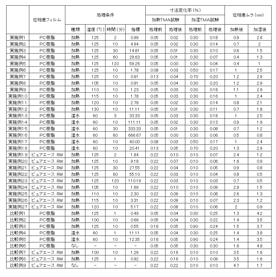
実施例1~12、実施例19~27、比較例1~3、および比較例7~8について、加熱処理条件の指標として、
10×t1/{(Tg-T1)2×A1 2}
および、
10×t1/{(Tg-T1)2×A2 2}
を算出した。ここで、T1は加熱処理工程での加熱温度(℃)、t1は加熱処理工程での加熱時間(分)、A1は加熱処理工程前の延伸フィルムの加熱TMA試験における収縮率(%)、A2は加熱処理工程前の延伸フィルムの加湿TMA試験における収縮率(%)とする。
実施例13~18および比較例4~5について、温水処理条件の指標として、
t2/A3 2
を算出した。ここで、t2は温水処理工程での浸漬時間(分)、A3は温水処理工程前の延伸フィルムの加湿TMA試験における収縮率(%)とする。
実施例1~27および比較例1~9の位相差フィルムを加湿TMA試験および加熱TMA試験に供し、それぞれの試験による寸法変化率を測定した。
さらに、実施例1~27および比較例1~9について、加湿位相差ムラおよび加熱位相差ムラを測定した。
それぞれの結果を表1に示す。
表1から明らかなように、実施例の位相差フィルムは、比較例の位相差フィルムに比べて、加熱処理または温水処理後のTMA試験での寸法変化率が小さく、円偏光板に用いた場合の位相差ムラも小さかった。
本発明の位相差フィルムは円偏光板に好適に用いられ、本発明の円偏光板は有機ELパネルに好適に用いられる。
10 保護層
20 偏光子
30 位相差層
40 第2の位相差層
100 円偏光板
20 偏光子
30 位相差層
40 第2の位相差層
100 円偏光板
Claims (12)
- 面内位相差がRe(450)<Re(550)の関係を満たす位相差フィルムを得る製造方法であって、
30℃からTg-25℃まで昇温して再度30℃に冷却することを3サイクル繰り返す加熱TMA試験において遅相軸方向の収縮率が0.4%以下であるか、または、25℃/25%RH、85℃/2%RH、85℃/85%RH、85℃/2%RHの順に環境を変化させる加湿TMA試験において遅相軸方向の収縮率が0.7%以下である延伸フィルムを、105℃以上の温度で2分間以上加熱する加熱処理工程を含む、
位相差フィルムの製造方法:
ここで、Re(450)およびRe(550)は、それぞれ、23℃における波長450nmおよび550nmの光で測定した面内位相差を表す。 - 前記加熱処理工程での加熱温度をT1(℃)とし、前記加熱処理工程での加熱時間をt1(分)とし、前記加熱処理工程前の前記延伸フィルムの前記加熱TMA試験における前記収縮率をA1としたとき、
10×t1/{(Tg-T1)2×A1 2}>2
を満たす、請求項1に記載の製造方法。 - 前記加熱処理工程での加熱温度をT1(℃)とし、前記加熱処理工程での加熱時間をt1(分)とし、前記加熱処理工程前の前記延伸フィルムの前記加湿TMA試験における前記収縮率をA2としたとき、
10×t1/{(Tg-T1)2×A2 2}>0.9
を満たす、請求項1に記載の製造方法。 - 面内位相差がRe(450)<Re(550)の関係を満たす位相差フィルムを得る製造方法であって、
25℃/25%RH、85℃/2%RH、85℃/85%RH、85℃/2%RHの順に環境を変化させる加湿TMA試験において遅相軸方向の収縮率が0.7%以下である延伸フィルムを、60℃以上の温水に3分間以上浸漬する温水処理工程を含む、
位相差フィルムの製造方法:
ここで、Re(450)およびRe(550)は、それぞれ、23℃における波長450nmおよび550nmの光で測定した面内位相差を表す。 - 前記温水処理工程での浸漬時間をt2(分)とし、前記温水処理工程前の前記延伸フィルムの前記加湿TMA試験における前記収縮率をA3としたとき、
t2/A3 2>20
を満たす、請求項4に記載の製造方法。 - 面内位相差がRe(450)<Re(550)の関係を満たし、
30℃からTg-25℃まで昇温して再度30℃に冷却することを3サイクル繰り返す加熱TMA試験において遅相軸方向の収縮率が0.1%以下であり、かつ、
25℃/25%RH、85℃/2%RH、85℃/85%RH、85℃/2%RHの順に環境を変化させる加湿TMA試験において遅相軸方向の収縮率が0.2%以下である、位相差フィルム:
ここで、Re(450)およびRe(550)は、それぞれ、23℃における波長450nmおよび550nmの光で測定した面内位相差を表す。 - ポリカーボネート樹脂およびポリエステルカーボネート系樹脂から選択される樹脂で形成されている、請求項6に記載の位相差フィルム。
- Re(450)/Re(550)が0.8~0.9である、請求項6または7に記載の位相差フィルム。
- 光弾性係数が1×10-12(m2/N)~40×10-12(m2/N)である、請求項6から8のいずれかに記載の位相差フィルム。
- 請求項6から9のいずれかに記載の位相差フィルムで構成された位相差層と、偏光子と、を有し、
前記位相差層の遅相軸と前記偏光子の吸収軸とのなす角度が35°~55°である、円偏光板。 - 枚葉状であり、
前記位相差層の中心部の面内位相差値をRA0とし、頂点部分の面内位相差値をRB0とし、
両面にガラスを貼り合せて85℃で240時間保持した後の、前記位相差層の中心部の面内位相差値をRA1とし、前記頂点部分の面内位相差値をRB1とし、
両面にガラスを貼り合せて65℃/90%RHで240時間保持した後の、前記位相差層の前記中心部の面内位相差値をRA2とし、前記頂点部分の面内位相差値をRB2としたとき、
(RA1-RB1)-(RA0-RB0)の絶対値が3nm以下であり、かつ
(RA2-RB2)-(RA0-RB0)の絶対値が3nm以下である、請求項10に記載の円偏光板。 - 保護フィルムと、前記位相差層と、前記偏光子と、屈折率楕円体がnz>nx=nyの関係を有する別の位相差層と、をこの順に有する、請求項10または11に記載の円偏光板。
Priority Applications (2)
| Application Number | Priority Date | Filing Date | Title |
|---|---|---|---|
| KR1020197038058A KR102518911B1 (ko) | 2017-06-28 | 2018-03-09 | 위상차 필름, 원편광판 및 위상차 필름의 제조 방법 |
| CN201880043387.5A CN110799869B (zh) | 2017-06-28 | 2018-03-09 | 相位差膜、圆偏振片及相位差膜的制造方法 |
Applications Claiming Priority (2)
| Application Number | Priority Date | Filing Date | Title |
|---|---|---|---|
| JP2017126608A JP6781111B2 (ja) | 2017-06-28 | 2017-06-28 | 位相差フィルム、円偏光板、および位相差フィルムの製造方法 |
| JP2017-126608 | 2017-06-28 |
Publications (1)
| Publication Number | Publication Date |
|---|---|
| WO2019003503A1 true WO2019003503A1 (ja) | 2019-01-03 |
Family
ID=64741275
Family Applications (1)
| Application Number | Title | Priority Date | Filing Date |
|---|---|---|---|
| PCT/JP2018/009158 Ceased WO2019003503A1 (ja) | 2017-06-28 | 2018-03-09 | 位相差フィルム、円偏光板、および位相差フィルムの製造方法 |
Country Status (5)
| Country | Link |
|---|---|
| JP (1) | JP6781111B2 (ja) |
| KR (1) | KR102518911B1 (ja) |
| CN (1) | CN110799869B (ja) |
| TW (2) | TWI757471B (ja) |
| WO (1) | WO2019003503A1 (ja) |
Families Citing this family (6)
| Publication number | Priority date | Publication date | Assignee | Title |
|---|---|---|---|---|
| JP6989852B2 (ja) | 2019-01-22 | 2022-02-03 | 横河電機株式会社 | 電界センサ |
| KR20220145350A (ko) * | 2020-03-18 | 2022-10-28 | 닛토덴코 가부시키가이샤 | 위상차층 및 점착제층 부착 편광판과, 해당 위상차층 및 점착제층 부착 편광판을 이용한 화상 표시 장치 |
| JP2023003918A (ja) * | 2021-06-25 | 2023-01-17 | 日東電工株式会社 | 位相差フィルム、偏光板および画像表示装置 |
| JP2023064220A (ja) * | 2021-10-26 | 2023-05-11 | 日東電工株式会社 | 位相差層付偏光板および画像表示装置 |
| JP2024010495A (ja) * | 2022-07-12 | 2024-01-24 | 日東電工株式会社 | 円偏光板および画像表示装置 |
| KR20240071630A (ko) * | 2022-11-16 | 2024-05-23 | 삼성에스디아이 주식회사 | 편광판 및 광학표시장치 |
Citations (6)
| Publication number | Priority date | Publication date | Assignee | Title |
|---|---|---|---|---|
| JP2008102498A (ja) * | 2006-09-22 | 2008-05-01 | Jsr Corp | 位相差フィルムの製造方法、位相差フィルムおよびその用途 |
| JP2008247934A (ja) * | 2007-03-29 | 2008-10-16 | Toray Ind Inc | 光学用フィルム |
| JP2012181536A (ja) * | 2005-06-10 | 2012-09-20 | Fujifilm Corp | セルロースアシレートフィルム、偏光板、位相差フィルム、光学補償フィルム、反射防止フィルム、並びに液晶表示装置 |
| WO2015072486A1 (ja) * | 2013-11-15 | 2015-05-21 | 日本ゼオン株式会社 | 位相差フィルムの製造方法 |
| JP2015127830A (ja) * | 2015-03-20 | 2015-07-09 | 日東電工株式会社 | 位相差フィルム |
| WO2016060144A1 (ja) * | 2014-10-17 | 2016-04-21 | コニカミノルタ株式会社 | 高分子組成物、光学フィルム、円偏光板及び表示装置 |
Family Cites Families (11)
| Publication number | Priority date | Publication date | Assignee | Title |
|---|---|---|---|---|
| JP2006171235A (ja) | 2004-12-14 | 2006-06-29 | Nitto Denko Corp | 円偏光板、及び光学フィルム、及び画像表示装置 |
| JP2006341393A (ja) * | 2005-06-07 | 2006-12-21 | Fujifilm Holdings Corp | セルロースアシレート樹脂フィルムの製造方法 |
| JP2006341394A (ja) * | 2005-06-07 | 2006-12-21 | Fujifilm Holdings Corp | 熱可塑性樹脂フィルムの製造方法 |
| US7505099B2 (en) * | 2005-08-17 | 2009-03-17 | Fujifilm Corporation | Optical resin film and polarizing plate and liquid crystal display using same |
| US20080049323A1 (en) * | 2006-07-27 | 2008-02-28 | Fujifilm Corporation | Optical film, production method of optical film, polarizing plate and liquid crystal display device |
| JP5134029B2 (ja) * | 2009-03-23 | 2013-01-30 | 富士フイルム株式会社 | セルロースアシレートフィルムとその製造方法、位相差フィルム、偏光板および液晶表示装置 |
| JP2012068611A (ja) * | 2010-04-19 | 2012-04-05 | Fujifilm Corp | セルロースアシレートフィルム、その製造方法、偏光板および液晶表示装置 |
| KR20140118595A (ko) * | 2013-03-29 | 2014-10-08 | 제일모직주식회사 | Oled용 편광판 및 이를 포함하는 광학표시장치 |
| JP5755674B2 (ja) * | 2013-03-29 | 2015-07-29 | 日東電工株式会社 | 位相差フィルムの製造方法および円偏光板の製造方法 |
| WO2015159679A1 (ja) * | 2014-04-16 | 2015-10-22 | コニカミノルタ株式会社 | 偏光板、偏光板の製造方法、液晶表示装置及び有機エレクトロルミネッセンス表示装置 |
| JP2017138582A (ja) * | 2016-01-29 | 2017-08-10 | 住友化学株式会社 | 偏光板の製造方法 |
-
2017
- 2017-06-28 JP JP2017126608A patent/JP6781111B2/ja active Active
-
2018
- 2018-03-09 WO PCT/JP2018/009158 patent/WO2019003503A1/ja not_active Ceased
- 2018-03-09 KR KR1020197038058A patent/KR102518911B1/ko active Active
- 2018-03-09 CN CN201880043387.5A patent/CN110799869B/zh active Active
- 2018-04-16 TW TW107112894A patent/TWI757471B/zh active
- 2018-04-16 TW TW111107145A patent/TWI799158B/zh active
Patent Citations (6)
| Publication number | Priority date | Publication date | Assignee | Title |
|---|---|---|---|---|
| JP2012181536A (ja) * | 2005-06-10 | 2012-09-20 | Fujifilm Corp | セルロースアシレートフィルム、偏光板、位相差フィルム、光学補償フィルム、反射防止フィルム、並びに液晶表示装置 |
| JP2008102498A (ja) * | 2006-09-22 | 2008-05-01 | Jsr Corp | 位相差フィルムの製造方法、位相差フィルムおよびその用途 |
| JP2008247934A (ja) * | 2007-03-29 | 2008-10-16 | Toray Ind Inc | 光学用フィルム |
| WO2015072486A1 (ja) * | 2013-11-15 | 2015-05-21 | 日本ゼオン株式会社 | 位相差フィルムの製造方法 |
| WO2016060144A1 (ja) * | 2014-10-17 | 2016-04-21 | コニカミノルタ株式会社 | 高分子組成物、光学フィルム、円偏光板及び表示装置 |
| JP2015127830A (ja) * | 2015-03-20 | 2015-07-09 | 日東電工株式会社 | 位相差フィルム |
Also Published As
| Publication number | Publication date |
|---|---|
| CN110799869A (zh) | 2020-02-14 |
| TW202223460A (zh) | 2022-06-16 |
| JP2019008252A (ja) | 2019-01-17 |
| CN110799869B (zh) | 2022-07-12 |
| TWI799158B (zh) | 2023-04-11 |
| KR102518911B1 (ko) | 2023-04-07 |
| KR20200018487A (ko) | 2020-02-19 |
| TW201905507A (zh) | 2019-02-01 |
| JP6781111B2 (ja) | 2020-11-04 |
| TWI757471B (zh) | 2022-03-11 |
Similar Documents
| Publication | Publication Date | Title |
|---|---|---|
| JP5528606B2 (ja) | 偏光板および有機elパネル | |
| JP6681934B2 (ja) | 偏光板および有機elパネル | |
| WO2019003503A1 (ja) | 位相差フィルム、円偏光板、および位相差フィルムの製造方法 | |
| JP6301885B2 (ja) | 光学補償層付偏光板およびそれを用いた有機elパネル | |
| TWI739941B (zh) | 寬頻帶波長薄膜及其製造方法以及圓偏光薄膜的製造方法 | |
| WO2014002929A1 (ja) | 偏光板および有機elパネル | |
| JP6712335B2 (ja) | 光学補償層付偏光板およびそれを用いた有機elパネル | |
| KR20220076468A (ko) | 위상차층 부착 편광판 및 이를 이용한 유기 일렉트로루미네센스 표시 장치 | |
| WO2018042878A1 (ja) | 偏光板 | |
| JP2025129163A (ja) | 曲面加工された偏光板およびその製造方法 | |
| JP7385380B2 (ja) | 位相差層およびハードコート層付偏光板の製造方法 | |
| CN110858011B (zh) | 相位差膜、带相位差层的偏振片及相位差膜的制造方法 | |
| JP7693300B2 (ja) | 位相差層付偏光板およびそれを用いた有機エレクトロルミネセンス表示装置 | |
| WO2022244301A1 (ja) | 円偏光板およびそれを用いた画像表示装置 | |
| JP7370177B2 (ja) | 位相差層付偏光板およびそれを用いた画像表示装置 | |
| JP6804168B2 (ja) | 位相差層付偏光板およびそれを用いた画像表示装置 | |
| JP7240365B2 (ja) | 円偏光板 | |
| JP2018109778A (ja) | 光学補償層付偏光板およびそれを用いた有機elパネル | |
| WO2023176367A1 (ja) | レンズ部、積層体、表示体、表示体の製造方法および表示方法 | |
| TW202339544A (zh) | 透鏡部、顯示體及顯示方法 | |
| TW202341811A (zh) | 透鏡部、顯示體及顯示方法 | |
| JP2025022188A (ja) | 位相差層付偏光板および該位相差層付偏光板を有する画像表示装置 | |
| JP2023166853A (ja) | レンズ部、積層体、表示体、表示体の製造方法および表示方法 |
Legal Events
| Date | Code | Title | Description |
|---|---|---|---|
| 121 | Ep: the epo has been informed by wipo that ep was designated in this application |
Ref document number: 18823277 Country of ref document: EP Kind code of ref document: A1 |
|
| ENP | Entry into the national phase |
Ref document number: 20197038058 Country of ref document: KR Kind code of ref document: A |
|
| NENP | Non-entry into the national phase |
Ref country code: DE |
|
| 122 | Ep: pct application non-entry in european phase |
Ref document number: 18823277 Country of ref document: EP Kind code of ref document: A1 |