WO2018235871A1 - 中空糸膜モジュールおよびろ過方法 - Google Patents
中空糸膜モジュールおよびろ過方法 Download PDFInfo
- Publication number
- WO2018235871A1 WO2018235871A1 PCT/JP2018/023481 JP2018023481W WO2018235871A1 WO 2018235871 A1 WO2018235871 A1 WO 2018235871A1 JP 2018023481 W JP2018023481 W JP 2018023481W WO 2018235871 A1 WO2018235871 A1 WO 2018235871A1
- Authority
- WO
- WIPO (PCT)
- Prior art keywords
- hollow fiber
- fiber membrane
- adhesive fixing
- fixing portion
- hollow
- Prior art date
- Legal status (The legal status is an assumption and is not a legal conclusion. Google has not performed a legal analysis and makes no representation as to the accuracy of the status listed.)
- Ceased
Links
Images


Classifications
-
- B—PERFORMING OPERATIONS; TRANSPORTING
- B01—PHYSICAL OR CHEMICAL PROCESSES OR APPARATUS IN GENERAL
- B01D—SEPARATION
- B01D63/00—Apparatus in general for separation processes using semi-permeable membranes
- B01D63/02—Hollow fibre modules
- B01D63/04—Hollow fibre modules comprising multiple hollow fibre assemblies
- B01D63/043—Hollow fibre modules comprising multiple hollow fibre assemblies with separate tube sheets
-
- C—CHEMISTRY; METALLURGY
- C02—TREATMENT OF WATER, WASTE WATER, SEWAGE, OR SLUDGE
- C02F—TREATMENT OF WATER, WASTE WATER, SEWAGE, OR SLUDGE
- C02F1/00—Treatment of water, waste water, or sewage
- C02F1/44—Treatment of water, waste water, or sewage by dialysis, osmosis or reverse osmosis
- C02F1/444—Treatment of water, waste water, or sewage by dialysis, osmosis or reverse osmosis by ultrafiltration or microfiltration
-
- B—PERFORMING OPERATIONS; TRANSPORTING
- B01—PHYSICAL OR CHEMICAL PROCESSES OR APPARATUS IN GENERAL
- B01D—SEPARATION
- B01D63/00—Apparatus in general for separation processes using semi-permeable membranes
- B01D63/02—Hollow fibre modules
- B01D63/031—Two or more types of hollow fibres within one bundle or within one potting or tube-sheet
-
- B—PERFORMING OPERATIONS; TRANSPORTING
- B01—PHYSICAL OR CHEMICAL PROCESSES OR APPARATUS IN GENERAL
- B01D—SEPARATION
- B01D63/00—Apparatus in general for separation processes using semi-permeable membranes
- B01D63/02—Hollow fibre modules
- B01D63/033—Specific distribution of fibres within one potting or tube-sheet
-
- C—CHEMISTRY; METALLURGY
- C02—TREATMENT OF WATER, WASTE WATER, SEWAGE, OR SLUDGE
- C02F—TREATMENT OF WATER, WASTE WATER, SEWAGE, OR SLUDGE
- C02F1/00—Treatment of water, waste water, or sewage
- C02F1/44—Treatment of water, waste water, or sewage by dialysis, osmosis or reverse osmosis
-
- C—CHEMISTRY; METALLURGY
- C02—TREATMENT OF WATER, WASTE WATER, SEWAGE, OR SLUDGE
- C02F—TREATMENT OF WATER, WASTE WATER, SEWAGE, OR SLUDGE
- C02F2103/00—Nature of the water, waste water, sewage or sludge to be treated
- C02F2103/007—Contaminated open waterways, rivers, lakes or ponds
-
- C—CHEMISTRY; METALLURGY
- C02—TREATMENT OF WATER, WASTE WATER, SEWAGE, OR SLUDGE
- C02F—TREATMENT OF WATER, WASTE WATER, SEWAGE, OR SLUDGE
- C02F2103/00—Nature of the water, waste water, sewage or sludge to be treated
- C02F2103/06—Contaminated groundwater or leachate
-
- C—CHEMISTRY; METALLURGY
- C02—TREATMENT OF WATER, WASTE WATER, SEWAGE, OR SLUDGE
- C02F—TREATMENT OF WATER, WASTE WATER, SEWAGE, OR SLUDGE
- C02F2103/00—Nature of the water, waste water, sewage or sludge to be treated
- C02F2103/08—Seawater, e.g. for desalination
-
- C—CHEMISTRY; METALLURGY
- C02—TREATMENT OF WATER, WASTE WATER, SEWAGE, OR SLUDGE
- C02F—TREATMENT OF WATER, WASTE WATER, SEWAGE, OR SLUDGE
- C02F2201/00—Apparatus for treatment of water, waste water or sewage
- C02F2201/002—Construction details of the apparatus
- C02F2201/004—Seals, connections
-
- C—CHEMISTRY; METALLURGY
- C02—TREATMENT OF WATER, WASTE WATER, SEWAGE, OR SLUDGE
- C02F—TREATMENT OF WATER, WASTE WATER, SEWAGE, OR SLUDGE
- C02F2303/00—Specific treatment goals
- C02F2303/04—Disinfection
Definitions
- the present invention relates to a hollow fiber membrane module for use in a filtration apparatus for removing or disinfecting a large amount of raw water such as river water, lake water, ground water, seawater, domestic drainage, or factory drainage, and a hollow fiber membrane module thereof Relating to the filtration method using
- hollow fiber membrane modules are roughly classified into internal pressure type and external pressure type.
- the external pressure type hollow fiber membrane module usually bundles several hundreds to several tens of thousands of hollow fiber membranes with a length of 200 to 3000 mm and an outer diameter of 0.1 to 5 mm, and stores them in a cylindrical housing. It is adhesively fixed to the inner wall of the case with a potting material (adhesive).
- the hollow fiber membrane end is opened at one bonding and fixing part, the hollow part is sealed at the other bonding and fixing part, and raw water is collected in the area sandwiched between the two bonding and fixing parts.
- a hollow fiber membrane is permeated by pressure supply, and the hollow fiber membrane end of the module of one end water collecting method in which the filtered water is taken out from the adhesion fixing portion opened by the hollow fiber end, and both adhesion fixing portions
- a plurality of through holes are provided in the adhesion / fixing part, which is on the lower side during use, and used as a supply port for treated water during filtration, or as a supply port for air or a washing drainage outlet in physical cleaning steps. It is used.
- cross flow filtration is usually performed to prevent the accumulation of suspended substances on the surface of the hollow fiber membrane, or periodically backwash. And physical scrubbing and air scrubbing to recover filtration performance and enable stable filtration operation.
- the water to be treated containing the suspended matter is supplied from the through hole provided in the lower adhesion fixing portion, and the concentrated water is discharged from the nozzle provided on the upper side surface of the housing.
- air is supplied from the lower through-hole, and clean water is supplied to the hollow portion of the hollow fiber membrane in the upper adhesion fixing portion, and the hollow fiber is flowed by the flow of air and water.
- the membrane is rocked to peel off the suspended matter deposited on the membrane surface and discharged from a nozzle provided on the upper side of the housing.
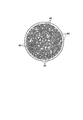
- FIG. 6 is a view showing an end face of the hollow fiber membrane bundle in the case where 12 cylindrical regulating members 41 are inserted and arranged.
- a large number of small double circles in FIG. 6 are each hollow fiber membranes, and a white portion excluding the hollow fiber membranes and the restriction member 41 indicates a potting material.
- the restriction member 41 is disposed as shown in FIG. 6, the density of the hollow fiber membrane at the central portion (the range of the dotted circle) of the hollow fiber membrane bundle is sparse compared to the outer peripheral portion other than the central portion. It turned out that it became.
- the length of the seri portion formed on the surface of each hollow fiber membrane by the potting material is longer at the central portion than at the outer peripheral portion I found that.
- the seri portion is a portion formed by raising the potting material along the surface of the hollow fiber membrane from the interface of the potting material in the housing.
- the adhesion fixing portion is formed, for example, by centrifugal adhesion. Specifically, potting material is injected into both ends of the housing, and centrifugal bonding is performed by horizontally rotating the housing into which the potting material is injected. The centrifugal bonding causes most of the potting material to move to both sides of the housing, thereby forming a bonding fixing portion, but some potting material remains along the surface of each hollow fiber membrane, and the remaining potting material A seri part is formed.
- the density of the hollow fiber membrane is low at the center of the end face of the hollow fiber membrane bundle, so when the potting material is injected, Relatively more potting material was injected than between the hollow fiber membranes in the outer peripheral portion.
- the potting material attached to the surface between the hollow fiber membranes in the central portion does not return to both sides of the hollow fiber membrane bundle, and as a result, the length of the central seri portion is long.
- This invention is made in view of the said situation, and it aims at providing the hollow fiber membrane module and filtration method which can suppress the fracture
- the hollow fiber membrane module of the present invention comprises a hollow fiber membrane bundle formed by bundling a plurality of hollow fiber membranes, a cylindrical housing for accommodating the hollow fiber membrane bundle, and hollow fibers at one end of the hollow fiber membrane.
- the first adhesive fixing portion for bonding and fixing the membranes and the hollow fiber membrane bundle and the housing inner wall with a resin material, and the hollow fiber membranes and the hollow fiber membrane bundle and the housing inner wall at the other end of the hollow fiber membrane
- a second adhesive fixing portion adhesively fixed by a resin material, and a regulating member provided on at least one of the first adhesive fixing portion and the second adhesive fixing portion to regulate the arrangement of the hollow fiber membrane;
- the range of a circle whose center is the center of the end face and whose radius is 1/2 of the end face is the central portion
- the area other than the part is the outer peripheral part
- the ratio of the total area of the end faces of the thick part of the hollow fiber membrane contained in the central part to the total area of the central part is preferably 50% or more.
- the hollow portion at one end of the hollow fiber membrane be closed and the hollow portion at the other end be open.
- the central portion at the outer end face of the housing of the first adhesive fixing portion or the second adhesive fixing portion on the end side where the hollow portion of the hollow fiber membrane is opened It is preferable that the ratio of the area ratio of the restriction member and the resin material to the total area of and the area ratio of the restriction member and the resin material to the entire area of the outer peripheral portion be 0.8 or more and 1.2 or less.
- the first adhesive fixing part or the second adhesive fixing part on the end side where the hollow part of the hollow fiber membrane is closed is a liquid supplied from the outside of the housing.
- at least one through hole is introduced into the space in the housing between the first adhesive fixing portion and the second adhesive fixing portion.
- the resin material in the housing is at least one of the first adhesive fixing portion and the second adhesive fixing portion on the end side where the hollow portion of the hollow fiber membrane is opened.
- the length from the interface of the seri portion formed by raising the resin material along the surface of the hollow fiber membrane from the interface of is 20 mm or less.
- the thickness of at least one of the first adhesive fixing part and the second adhesive fixing part on the end side where the hollow part of the hollow fiber membrane is opened is minimized. It is preferable that the minimum thickness D0 of and the maximum thickness D1 of the largest part satisfy D1 ⁇ 120% ⁇ D0.
- the regulating member preferably has a cylindrical shape.
- the regulating member is preferably disposed in both the central portion and the outer peripheral portion.
- the filtration method of the present invention is characterized in that filtration is performed using the hollow fiber membrane module of the present invention.
- the restricting member and resin for the entire area of the central portion are arranged such that the ratio of the area ratio of the material to the ratio of the area ratio of the regulating member and the resin material to the total area of the outer peripheral portion is 0.8 or more and 1.2 or less. Therefore, the length of the seri portion formed in the hollow fiber membrane at the central portion can be shortened, and thereby the breakage of the hollow fiber membrane can be suppressed.
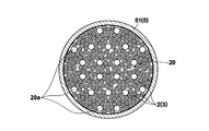
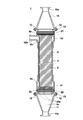
- FIG. 1 The figure which shows schematic structure of one Embodiment of the hollow fiber membrane module of this invention Sectional view of the hollow fiber membrane module shown in FIG.
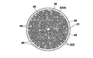
- the figure which shows the external appearance of the protection member provided in the housing The figure which shows the end surface of the 2nd adhesion
- FIG. 1 is a view showing a schematic configuration of a hollow fiber membrane module of the present embodiment.
- the up-down direction is shown by the arrow.
- the vertical direction shown in FIG. 1 will be described as the vertical direction of the hollow fiber membrane module 1.
- the hollow fiber membrane module 1 of the present embodiment includes a hollow fiber membrane bundle 3 in which a plurality of hollow fiber membranes 2 are bundled, and a cylindrical housing 5 for accommodating the hollow fiber membrane bundle 3. Is provided.
- FIG. 1 the cross-sectional view which removed the front half about the housing 5 and the caps 10 and 11 mentioned later is shown.
- a reverse osmosis membrane, a nanofiltration membrane, an ultrafiltration membrane, and a microfiltration membrane can be used.
- the material of the hollow fiber membrane is not particularly limited, and polysulfone, polyethersulfone, polyacrylonitrile, polyimide, polyetherimide, polyamide, polyetherketone, polyetheretherketone, polyethylene, polypropylene, poly (4-methylpentene), ethylene And vinyl alcohol copolymers, cellulose, cellulose acetate, polyvinylidene fluoride, ethylene-tetrafluoroethylene copolymers, polytetrafluoroethylene and the like, and these composite materials can also be used.
- the hollow fiber membrane preferably has an inner diameter of 50 to 3000 ⁇ m, more preferably 500 to 2000 ⁇ m. In addition, those having an inside diameter / outside diameter ratio of 0.3 to 0.8 are preferably used.
- Caps 10 and 11 for pipe connection provided with pipelines 10a and 11a to which pipes are connected are respectively provided at both end openings of the housing 5, and the caps 10 and 11 for pipe connection are connected by the clamp 13 to the housing Fixedly attached to 5.
- An annular groove is formed on the end face of the cap 10, 11 on the housing 5 side and the end face of the housing 5 on the cap 10, 11 side, and the sanitary gasket 12 is held by this groove.
- the sanitary gasket 12 seals between the housing ends and the caps 10 and 11.
- the housing 5 is a straight tubular member disposed between the first tubular member 51, the second tubular member 52 integrally formed with the nozzle 52a, and the first tubular member 51 and the second tubular member 52.
- the third cylindrical member 53 is joined to each other.
- the nozzle 52 a is provided on the side of the upper end of the housing 5 and is provided so as to protrude in the direction orthogonal to the longitudinal direction of the housing 5.
- the nozzle 52a is a nozzle from which the concentrated water is discharged in the process of the external pressure filtration process.
- the hollow fiber membrane module 1 of the present embodiment is erected so that the longitudinal direction thereof is in the vertical direction, and the nozzle 52a is disposed in the upper side in the vertical direction.
- a flow straightening cylinder 7 is attached to an end of the upper side (nozzle 52 a side) of the hollow fiber membrane bundle 3.
- the flow straightening cylinder 7 is formed in a cylindrical shape, provided between the opening on the inner wall side of the housing 5 of the nozzle 52 a and the hollow fiber membrane bundle 3 and provided so as to surround the outer periphery of the hollow fiber membrane bundle 3 ing.
- the flow straightening cylinder 7 is provided to secure a distance between the hollow fiber membrane bundle 3 and the inner wall of the housing 5 in the vicinity of the nozzle 52 a. Thereby, when concentrated water is discharged from the nozzle 52a, it can suppress that the hollow fiber membrane 2 swings to the nozzle 52a side, and can suppress breakage of the hollow fiber membrane 2.
- the flow straightening cylinder 7 is provided with a plurality of through holes 30.
- the through hole 30 of the flow straightening cylinder 7 is preferably formed in an area other than the area facing the opening on the inner surface side of the housing 5 of the nozzle 52a, and not formed in the area facing the opening.
- the straightening cylinder 7 is provided with a flange 7 a, and the straightening cylinder 7 is positioned by sandwiching the flange 7 a between the second cylindrical member 52 and the third cylindrical member 53.
- the upper end of the flow straightening cylinder 7 is bonded and fixed in a second bonding and fixing portion 21 described later.
- the fixing portion 20 and the second adhesive fixing portion 21 are formed.
- Annular asperities 5a are formed on the inner walls of both ends of the housing 5, and the potting material flows into the grooves of the asperities 5a, whereby the first adhesive fixing portion 20 and the second adhesive fixing portion 21 are formed.
- An annular uneven structure is formed on the side surface.
- polymer materials such as epoxy resin, vinyl ester resin, urethane resin, unsaturated polyester resin, olefin polymer, silicone resin, and fluorine-containing resin are preferable, and any of these polymer materials may be used.
- a plurality of polymer materials may be used in combination.
- a region 5b where the water to be treated flows into the outside of the hollow fiber membrane 2 between the first adhesive fixing portion 20 and the second adhesive fixing portion 21 formed at both ends of the hollow fiber membrane bundle 3 Region) is formed.
- FIG. 2 is a cross-sectional view of the hollow fiber membrane module 1 shown in FIG.
- the through hole 20 a is formed in parallel with the longitudinal direction of the housing 5 and is a hole that brings the above-mentioned outer region 5 b into communication with the opposite outer region 5 c across the first adhesive fixing portion 20.
- the plurality of through holes 20 a are formed to be uniformly distributed in the first bonding and fixing portion 20.
- the present invention is not limited to this, and other arrangements may be made.
- each hollow fiber membrane 2 in the side provided with penetration hole 20a is closed, and the hollow part of each hollow fiber membrane 2 in the opposite side to the side in which penetration hole 20a is formed is opened. There is.
- the water to be treated liquid to be treated
- the water to be treated flows through the through hole 20 a It passes and is supplied to the outer side area
- the water to be treated supplied to the outer region 5 b permeates the protective member 8 and then permeates from the outer surface of each hollow fiber membrane 2, and the filtered water which has passed through the hollow portion of each hollow fiber membrane 2 has a cap 10.
- the concentrated water is discharged from the nozzle 52a.
- the cleaning process by air scrubbing is periodically performed. Specifically, clean water is supplied from the upper second adhesive fixing portion 21 side, and at the same time, air is supplied to the through holes 20a of the lower first adhesive fixing portion 20, and both supplied fluids are By discharging from the nozzle 52a of the second cylindrical member 52, the hollow fiber membrane 2 is shaken, and a process of removing dirt attached to the membrane surface is performed. At the time of this air scrubbing, there is a problem that each hollow fiber membrane 2 in the vicinity of the second adhesive fixing portion 21 is easily broken due to its shaking.
- the seri portion is a portion formed by raising the potting material along the surface of the hollow fiber membrane 2 from the interface of the potting material.
- each hollow fiber membrane 2 is formed so that the density of the hollow fiber membrane 2 as a whole becomes uniform at the outer end face of the housing 5 of the second bonding / fixing portion 21. Deploy.
- FIG. 3 is a schematic view of the end face of the second adhesive fixing part 21 of the hollow fiber membrane module 1 shown in FIG. 1 as viewed from the direction of arrow A. As shown in FIG.
- a cylindrical restriction member 40 is provided in the second adhesion fixing portion 21.
- the regulating member 40 is a member formed of a cylindrical resin.
- white parts other than the hollow fiber membrane 2 and the limitation member 40 show a potting material.
- restriction members 40 are arranged so as to be evenly distributed over the entire end face of the hollow fiber membrane bundle 3.
- the range of the circle which makes the center of the above-mentioned end face the central point and makes 1/2 radius of the above-mentioned end face radius is central part,
- the ratio of the area ratio of the restricting member 40 and the potting material to the total area of the central portion and the area ratio of the restricting member 40 and the potting material to the total area of the outer peripheral portion is 0.8
- the hollow fiber membrane 2 and the regulating member 40 are disposed so as to be 1.2 or less.
- the range of the circle indicated by the dotted line in FIG. 3 is the central portion, and the range outside the central portion is the outer circumferential portion.
- the restricting member 40 is disposed at both the central portion and the outer peripheral portion.
- the hollow fiber membranes 2 in the central portion are arranged by arranging the hollow fiber membranes 2 so that the density of the hollow fiber membranes 2 as a whole becomes uniform at the end face of the second adhesive fixing portion 21.
- the density of the hollow fiber membrane 2 can be made more difficult to break because the density of the hollow fiber membrane 2 can be shortened at the time of forming the second adhesive fixing part 21 than in the prior art. The reason why the length of the seri can be shortened will be described in detail later.
- the ratio of the total area of the end face of the thick part of the hollow fiber membrane 2 contained in the central part to the total area of the central part is 50% or more preferable.
- the length from the interface of the potting material of the seri part mentioned above is 20 mm or less.
- the interface of the potting material is the surface of the potting material except for the seri portion formed between the adjacent hollow fiber membranes 2.
- the length of the seri portion referred to herein means the length of the longest seri portion among the plurality of seri portions formed along the hollow fiber membranes 2.
- FIG. 4 is a view schematically showing the seri portion 50. As shown in FIG. In FIG. 4, the hatched range P is the potting material, and the portion shaded diagonally above the interface S of the potting material P is the seri portion 50. It is preferable that the length L of the longest seri portion 50 of the seri portion 50 of each hollow fiber membrane 2 be 20 mm or less. More preferably, it is 5 mm or less.
- the minimum thickness D0 of the minimum portion and the maximum thickness D1 of the maximum portion satisfy D1 ⁇ 120% ⁇ D0. That is, with regard to the thickness of the second adhesion fixing portion 21, it is preferable that the variation be smaller.
- the thickness of the second adhesive fixing portion 21 is, as shown in FIG. 4, a potting material for forming the second adhesive fixing portion 21 from the outer end face 21 a of the housing 5 of the second adhesive fixing portion 21. It is the thickness to the interface S.
- FIG. 4 shows the case where the above-described minimum thickness D0 and maximum thickness D1 are equal.
- the thickness of the central portion of the adhesive fixing portion becomes thicker than the thickness of the outer peripheral portion.
- the variation in thickness was large.
- the thickness variation of the adhesive fixing portion is large, there is a problem that the withstand voltage is partially weak.
- the problem is solved by reducing the thickness variation of the adhesive fixing portion. can do.
- FIG. 5 shows the appearance of the protective member 8 provided in the housing 5.
- the hollow fiber membrane bundle 3 and the flow straightening cylinder 7 shown in FIG. 1 are not shown.
- the protection member 8 is not shown.
- a protective member 8 is provided so as to wrap substantially the entire outer peripheral surface of the hollow fiber membrane bundle 3.
- the protection member 8 used in the present embodiment is a member in which a net-like member as shown in FIG. 5 is formed in a tubular shape, and has flexibility.
- the material of the protective member 8 in the form of a net includes PFA (tetrafluoroethylene-perfluoroalkyl vinyl ether copolymer), FEP (tetrafluoroethylene-hexafluoropropylene copolymer (4.6 fluoride)), ETFE (tetra It is desirable to use a heat-resistant material such as fluoroethylene / ethylene copolymer), PTFE (polytetrafluoroethylene (tetrafluorinated)), polysulfone or the like.
- Both ends of the protective member 8 are located in the first adhesive fixing portion 20 and the second adhesive fixing portion 21 respectively, and are fixed by the first adhesive fixing portion 20 and the second adhesive fixing portion 21.
- a predetermined number of hollow fiber membranes 2 are prepared as a bundle to produce a hollow fiber membrane bundle 3. Subsequently, the opening at one end of each hollow fiber membrane 2 of the hollow fiber membrane bundle 3 is sealed with a plug.
- a hot melt adhesive is used as the seal, but other materials may be used.
- the first cylindrical member 51 and the second cylindrical member 52 are joined to both ends of the third cylindrical member 53 to form the housing 5, and the flow straightening cylinder 7 is attached to the module case main body Is formed. Then, the outer periphery of the hollow fiber membrane bundle 3 whose opening at one end is sealed is wrapped by the protective member 8, and the hollow fiber membrane bundle 3 wrapped by the protective member 8 is inserted into the housing 5. At this time, the hollow fiber membrane bundle 3 is inserted so that the side where the hollow portion is sealed is positioned on the second cylindrical member 52 side.
- the restriction member 40 is inserted, and each hollow such that the density of the hollow fiber membrane 2 becomes uniform at the end as described above The arrangement of the fiber membrane 2 is adjusted.
- the columnar member is inserted at a position where the through hole 20a is to be formed.
- a container for forming an adhesive fixing portion is attached to both ends of the housing 5, and potting material is injected into both ends of the housing 5. Then, centrifugal bonding is performed by rotating the housing 5 in which the potting material is injected in the horizontal direction. Most of the potting material is shifted to both sides of the housing 5 by this centrifugal bonding, thereby forming the first bonding and fixing portion 20 and the second bonding and fixing portion 21. However, a part of the potting material is each hollow fiber membrane The remaining potting material remains along the surface 2 to form a seri portion.
- the density of the hollow fiber membrane is low at the center of the end face of the hollow fiber membrane bundle, so when the potting material is injected, Relatively more potting material was injected than between the hollow fiber membranes in the outer peripheral portion.
- the potting material attached to the surface between the hollow fiber membranes in the central portion does not return to both sides of the hollow fiber membrane bundle, and as a result, the length of the seri portion becomes longer and the air scrubbing described above is performed. There is a problem that the hollow fiber membrane is easily broken in the vicinity of the seri portion.
- the arrangement of the hollow fiber membranes 2 and the restriction member 40 is adjusted so that the density of the hollow fiber membranes 2 becomes uniform at the end face of the hollow fiber membrane bundle 3.
- the density of each hollow fiber membrane 2 in the central part of the membrane bundle 3 can be made higher than in the prior art, whereby relative to the hollow fiber membranes in the central part at the time of forming the second adhesive fixing part 21. Can prevent the potting material from being injected. Therefore, since the length of a seri part can be shortened, hollow fiber membrane 2 can be made hard to break.
- the plurality of through holes 20 a are formed by removing the columnar members on the first adhesive fixing portion 20 side.
- the hollow portion of the hollow fiber membrane bundle 3 on the first cylindrical member 51 side is closed by the potting material. After curing of the potting material, complete curing at high temperature may be carried out if necessary.
- the container for forming the adhesive fixing portion is removed, and the end portion of the second adhesive fixing portion 21 on the second cylindrical member 52 side is cut to make the hollow.
- the hollow portion of the yarn membrane bundle 3 is opened.
- caps 10 and 11 for pipe connection are attached to the both ends of the housing 5 to which the hollow fiber membrane bundle 3 is adhesively fixed via the sanitary gasket 12 and fastened and fixed by the clamps 13, respectively. Inspection, trial operation, and the like are performed, and it is confirmed that manufacturing can be performed as specified, and the hollow fiber membrane module 1 is completed.
- centrifugal bonding is performed in this embodiment, the present invention is not limited to this, and the stationary bonding in which the longitudinal direction of the housing 5 is disposed in the vertical direction and the potting material is injected from the lower end of the housing 5 is performed.
- the first adhesive fixing portion 20 and the second adhesive fixing portion 21 may be formed by this.
- the tip end portion of the regulating member 40 installed in the second bonding and fixing portion 21 be formed in a tapered shape in the longitudinal direction, for example, by forming it in a conical shape.
- the insertability to the hollow fiber membrane bundle 3 can be improved.
- the restriction member 40 is inserted into the hollow fiber membrane bundle 3, the surface of the hollow fiber membrane 2 can be prevented from being damaged.
- the cross-sectional shape of the regulating member 40 is not particularly limited, and may be, for example, a circle, an oval, a quadrangle, a hexagon, a sector such as a polygon or a plate, but it is inserted into the hollow fiber membrane bundle 3 It is preferable that the hollow fiber membrane 2 be circular or elliptical without any risk of damaging the hollow fiber membrane 2.
- the columnar members installed in the first adhesive fixing portion 20 are removed after completion of adhesion as described above, and have a length equal to or greater than the thickness of the first adhesive fixing portion 20 in order to form the through holes 20a. It is desirable to have.
- the tip end portion of the columnar member is also formed in a tapered shape in the longitudinal direction, for example, by forming it in a conical shape.
- the cross-sectional shape of the columnar member is not particularly limited, and may be, for example, a polygon such as a circle, an ellipse, a quadrangle, a hexagon, or a sector or a plate shape. It is preferable that the fiber membrane 2 be circular or oval without any risk of damage.
- a polymer material, an inorganic material, a metal material, etc. can be used as a material of a columnar member, although it does not specifically limit, It forms with a material weak in the adhesive force with a potting material, and sets it as a peelable structure. Is preferred.
- the cross-sectional shape in the longitudinal direction of the columnar member is preferably circular or elliptical.
- the hollow fiber membrane module 1 of the present embodiment is an external pressure type hollow fiber membrane module having a through hole 20a in the first adhesive fixing portion 20, and the restriction member 40 is provided only in the second adhesive fixing portion 21.
- the present invention is applicable to other hollow fiber membrane modules. Specifically, for example, it is also applicable to an external pressure type hollow fiber membrane module in which the water to be treated flows in from the nozzle formed on the side surface of the housing, and in this case, the regulation members are provided in the adhesive fixing portions at both ends. You may
- the ratio of the area ratio of the restricting member and the potting material to the entire area of the central portion and the area ratio of the restricting member and the potting material to the entire area of the outer peripheral portion is 0.8
- the hollow fiber membrane and the regulating member may be arranged so as to be 1.2 or less.
- the length of the seri portion 21 disposed on the upper side it is more preferable to set the length of the seri portion to 20 mm or less, but the present invention is not limited thereto.
- the first adhesive fixing portion and the second adhesive fixing portion In the case where the hollow portion of the hollow fiber membrane is opened in both of the adhesive fixing portions, the length of the seri portion is preferably 20 mm or less in both the first adhesive fixing portion and the second adhesive fixing portion. That is, it is preferable that the length of the seri portion be 20 mm or less in the adhesion fixing portion on the end portion side where the hollow portion of the hollow fiber membrane is opened.
- the thickness of the first adhesive fixing portion 20 and the second adhesive fixing portion 21 as in the hollow fiber membrane module 1 of the above embodiment an end portion where the hollow portion of the hollow fiber membrane 2 is opened. It is more preferable that the minimum thickness D0 and the maximum thickness D1 of the second adhesion fixing portion 21 on the side satisfy D1 ⁇ 120% ⁇ D0, but the present invention is not limited thereto.
- the first adhesion fixing portion When the hollow portion of the hollow fiber membrane is opened in both the second adhesive fixing portion, the minimum thickness D0 and the maximum thickness D1 are both in the first adhesive fixing portion and the second adhesive fixing portion. It is preferable to satisfy D1 ⁇ 120% ⁇ D0. That is, it is preferable that the minimum thickness D0 and the maximum thickness D1 satisfy D1 ⁇ 120% ⁇ D0 in the adhesion fixing portion on the end side where the hollow portion of the hollow fiber membrane is opened.
- the present invention may be applied to at least one of the adhesive fixing portions of the internal pressure type hollow fiber membrane module.
- Example 1 A bundle of 11,000 hollow fiber membranes (manufactured by Asahi Kasei Corp.) made of PVDF (polyfluorinated bilinidene) closed at a hollow portion at one end was inserted into a housing having a second cylindrical member with a flow straightening cylinder with an inner diameter of 154 mm mounted inside.
- the hollow fiber membrane used has an average pore diameter of 0.1 ⁇ m, an inner diameter of 0.6 mm, and an outer diameter of 1.0 mm.
- a cylindrical regulating member 40 with an outer diameter of 11 mm (adhesion similar to the potting material described below in advance is used as a mold
- eight tubes were uniformly inserted and arranged so as to be evenly distributed, as shown in FIG.
- the columnar member was inserted at a position where a through hole is to be formed.
- the container for forming an adhesive fixing portion to which the potting material introduction tube is attached is fixed to both ends of the housing 5 and the potting material is fixed in the first and second cylindrical members of the housing while rotating horizontally.
- a potting material a two-component thermosetting urethane resin (manufactured by San Yurec Co., Ltd .: SA-6330A2 / SA-6330B5 (trade name)) was used.
- SA-6330A2 / SA-6330B5 trade name
- the end on the second cylindrical member side of the housing was cut to open the hollow portion on the side where the hollow portion was closed at the stage before bonding.
- the columnar members were removed from the first adhesion fixing portion on the first cylindrical member side to form a plurality of through holes.
- a circle connecting the hollow fiber membranes present at the outermost periphery of the cut end face of the second adhesive fixing portion is taken as a cut end face circle, and the center of the cut end face circle is taken as the central point.
- the area ratio of the potting material of the central portion and the outer peripheral portion is 46.5% and 47. It was 4%. That is, the ratio of the area ratio of the potting material and the regulating member in the central portion to the area ratio of the potting material and the regulating member in the outer peripheral portion was 1.0.
- the area ratio of the potting material and the regulating member was determined by the following method. First, the cut end surface was photographed in close-up mode with a setting of 2,000,000 pixels or more by a digital camera at an illuminance of 500 lux or more. Thereafter, the obtained photograph data was opened with the image analysis software Win Roof 6.1.3, and converted into a monochrome image by the "monochrome image conversion” command. Then, the color tone was reversed by the "invert” command, only the cut end circle was selected, and the "brightness / contrast” command was emphasized by the contrast "100".
- the image is binarized with the threshold value "140" with the “Binarize with single threshold value” command of "Binary processing", and the area ratio is selected with the "total area / number" command of "Measurement”. The value of the area ratio was determined by carrying out.
- the effective membrane length of the present hollow fiber membrane module is 2 m.
- Clean water was supplied at a flow rate of 8 m 3 / hr from the upper second adhesive fixing portion side, and at the same time, air was supplied at a flow rate of 7 m 3 / hr to the through holes of the lower first adhesive fixing portion. Both supplied fluids were discharged from the nozzle of the upper second tubular member. The above operation was carried out continuously except at the time of the leak test performed every one month. The water temperature was maintained at 5 ° C. during operation.
- the membrane module is disassembled to confirm the state of the second adhesive fixing part on the filtration side, the thickness of the second adhesive fixing part on the filtration side is in the range of 33 mm to 37 mm, and The length of the part was at most 10 mm.
- Comparative example 1 A bundle of 11,000 hollow fiber membranes (manufactured by Asahi Kasei Corp.) made of PVDF (polyfluorinated bilinidene) closed at a hollow portion at one end was inserted into a housing having a second cylindrical member with a flow straightening cylinder with an inner diameter of 154 mm mounted inside.
- the hollow fiber membrane used has an average pore diameter of 0.1 ⁇ m, an inner diameter of 0.6 mm, and an outer diameter of 1.0 mm.
- FIG. 6 is a figure which shows the end surface of the 2nd adhesion
- the columnar member was inserted at a position where a through hole is to be formed.
- the container for forming an adhesive fixing portion to which the potting material introduction tube is attached is fixed to both ends of the housing 5 and the potting material is fixed in the first and second cylindrical members of the housing while rotating horizontally.
- a potting material a two-component thermosetting urethane resin (manufactured by San Yurec Co., Ltd .: SA-6330A2 / SA-6330B5 (trade name)) was used.
- SA-6330A2 / SA-6330B5 trade name
- the end on the second cylindrical member side of the housing was cut to open the hollow portion on the side where the hollow portion was closed at the stage before bonding.
- the columnar members were removed from the first adhesion fixing portion on the first cylindrical member side to form a plurality of through holes.
- a circle connecting the hollow fiber membranes present at the outermost periphery of the cut end face of the second adhesive fixing portion is taken as a cut end face circle, and the center of the cut end face circle is taken as the central point.
- the area ratio of the potting material of the central portion and the outer peripheral portion is 60.9% and 48. It was 3%. That is, the ratio of the area ratio of the potting material and the regulating member in the central portion to the area ratio of the potting material and the regulating member in the outer peripheral portion was 0.79.
- the range of the dotted-line circle shown in FIG. 6 is a center part, and the range other than that is an outer peripheral part.
- the effective membrane length of the present hollow fiber membrane module is 2 m.
- Clean water was supplied at a flow rate of 8 m 3 / hr from the upper second adhesive fixing portion side, and at the same time, air was supplied at a flow rate of 7 m 3 / hr to the through holes of the lower first adhesive fixing portion. Both supplied fluids were discharged from the nozzle of the upper second tubular member. The above operation was carried out continuously except at the time of the leak test performed every one month. The water temperature was maintained at 5 ° C. during operation.
- the membrane module is disassembled to confirm the state of the second adhesive fixing part on the filtration side, the thickness of the second adhesive fixing part on the filtration side is in the range of 29 mm to 40 mm, and The length of the part was at most 22 mm.
Landscapes
- Chemical & Material Sciences (AREA)
- Chemical Kinetics & Catalysis (AREA)
- Engineering & Computer Science (AREA)
- Life Sciences & Earth Sciences (AREA)
- Hydrology & Water Resources (AREA)
- Environmental & Geological Engineering (AREA)
- Water Supply & Treatment (AREA)
- Organic Chemistry (AREA)
- Separation Using Semi-Permeable Membranes (AREA)
- Artificial Filaments (AREA)
- Manufacturing & Machinery (AREA)
Abstract
中空糸膜束と、ハウジングと、中空糸膜束の両端部において、中空糸膜同士および中空糸膜束とハウジング内壁とをポッティング材によって接着固定する第1の接着固定部および第2の接着固定部と、中空糸膜の配置を規制する規制部材40とを備え、第1の接着固定部および第2の接着固定部の少なくとも一方のハウジングの外側の端面において、端面の中心を中心点とし端面の半径の1/2を半径とする円の範囲を中央部とし、その中央部以外の範囲を外周部とした場合に、中央部の全面積に対する規制部材40およびポッティング材の面積比率と、外周部の全面積に対する規制部材40およびポッティング材の面積比率との比が、0.8以上1.2以下である。
Description
本発明は、河川水、湖沼水、地下水、海水、生活排水、または工場排水等の大量の原水について、除濁または除菌などを行うろ過装置に用いられる中空糸膜モジュールおよびその中空糸膜モジュールを用いたろ過方法に関する。
一般に中空糸膜モジュールは、内圧式と外圧式とに大別される。そのうち外圧式中空糸膜モジュールは、通常、長さ200~3000mm、外径0.1~5mmの中空糸膜を数百~数万本束ねて筒状のハウジングに収納し、その両側端部をポッティング材(接着剤)でケース内壁に接着固定している。その両端部を接着固定するにあたり、一方の接着固定部では中空糸膜端を開口させ、他方の接着固定部は中空部を封止し、この両接着固定部間に挟まれた領域に原水を加圧供給することによって中空糸膜を透過させ、そのろ過水を中空糸端部が開口した接着固定部から取り出すようにした片端集水方式のモジュールと、両方の接着固定部で中空糸膜端を開口させて両端部から透過液を取り出すようにした両端集水方式のモジュールとがある。さらに、使用時に下方側になる接着固定部に複数の貫通孔が設けられており、ろ過処理時の被処理水の供給口として利用したり、物理洗浄工程における空気の供給口や洗浄排水出口として利用される。
このような外圧式中空糸膜モジュールを除菌や除濁目的で使用する場合、通常、クロスフローろ過を行って中空糸膜表面への懸濁物質の蓄積を防止したり、定期的に逆洗やエアスクラビングなどの物理洗浄を行ってろ過性能を回復させ、安定なろ過運転を可能にしている。
外圧ろ過処理の際には、下側の接着固定部に設けられた貫通孔から懸濁物質を含んだ被処理水を供給し、ハウジング上部側面に設けられたノズルから濃縮水を排出する。また、エアスクラビングによる洗浄の際には、下側の貫通孔から空気を供給するとともに、上側の接着固定部における中空糸膜の中空部に清浄水を供給し、空気および水の流れにより中空糸膜を揺り動かして膜表面に堆積した懸濁物質を剥ぎ取り、ハウジング上部側面に設けられたノズルから排出する。
このようなエアスクラビング洗浄の際、中空糸膜が揺動することによって、接着固定部内側表面付近の中空糸膜へ応力が集中し、これにより中空糸膜が破断しやすいという問題がある。
特に、上述したようにハウジング内に中空糸膜束を収容して両端を接着固定部で固定する場合、中空糸膜の密度分布に偏りが生じ易いが、大きな偏りを持ったまま中空糸膜モジュールを形成してしまうと、上述した中空糸膜の揺動がより大きくなり、結果として中空糸膜が破断しやすくなる。
そこで、中空糸膜の密度分布の偏りを防止するために、たとえば特許文献1~3には、中空糸膜束の端部の接着固定部内に、中空糸膜の密度分布の偏りを防止する規制部材を設けた中空糸膜モジュールが開示されている。
しかしながら、特許文献1~特許文献3に記載の中空糸膜モジュールのように、たとえば十字形状の規制部材を中空糸膜束の中央に設けた場合、中空糸膜が分布する区間を規制部材によって区切ることによって大まかな中空糸膜の密度分布を調整することは可能であるが、実際には、中空糸膜の密度を全体として均一にすることは困難であり、相対的に中空糸膜の密度が低い部分が形成される。
また、規制部材の形状としては、十字形状に限らず、円柱形状の規制部材を中空糸膜束内に複数挿入する方法もある。図6は、円柱形状の規制部材41を12本挿入して配置した場合の中空糸膜束の端面を示す図である。図6における多数の小さい2重丸が各中空糸膜であり、中空糸膜と規制部材41を除く白色部分がポッティング材を示している。図6に示すように規制部材41を配置した場合、中空糸膜束の中央部(点線の円の範囲)の中空糸膜の密度が、中央部以外の外周部と比較して疎な状態となることが分かった。そして、中空糸膜束の長さ方向に沿った断面内部を確認すると、ポッティング材によって各中空糸膜の表面に形成されるセリ部の長さが、外周部よりも中央部において長くなっていることが分かった。なお、セリ部とは、ハウジング内のポッティング材の界面から中空糸膜の表面に沿ってポッティング材がせりあがって形成された部分である。そして、このセリ部が長い場合、ポッティング材の界面近傍において中空糸膜が柔軟に折れ曲がることができないため、上述したような中空糸膜の搖動を吸収することができず、より破断しやすいことが分かった。
ここで、空糸膜束の中央部の中空糸膜の密度が外周部と比較して疎な状態である場合に、セリ部の長さが外周部よりも長くなる理由について、詳細に説明する。上述したような中空糸膜モジュールを製造する際には、たとえば遠心接着によって接着固定部が形成される。具体的には、ハウジングの両端部にポッティング材が注入され、そのポッティング材が注入されたハウジングを水平方向に回転させることによって遠心接着が行われる。この遠心接着によって大部分のポッティング材がハウジングの両側に寄り、これにより接着固定部が形成されるが、一部のポッティング材が各中空糸膜の表面に沿って残り、この残ったポッティング材によってセリ部が形成される。
従来の中空糸膜モジュールでは、上述したように中空糸膜束の端面の中央部において中空糸膜の密度が低くなっていたので、ポッティング材を注入した際、中央部の中空糸膜間に対して外周部の中空糸膜間よりも相対的に多くのポッティング材が注入されていた。これにより遠心接着したとしても、中央部の中空糸膜間の表面に付着したポッティング材が中空糸膜束の両側に戻りきらず、結果として中央部のセリ部の長さが長くなっていた。
本発明は、上記事情に鑑みてなされたものであり、中空糸膜の破断を抑制することができる中空糸膜モジュールおよびろ過方法を提供することを目的とするものである。
本発明の中空糸膜モジュールは、複数の中空糸膜を束ねた中空糸膜束と、中空糸膜束が収容される筒状体のハウジングと、中空糸膜の一方の端部において、中空糸膜同士および中空糸膜束とハウジング内壁とを樹脂材によって接着固定する第1の接着固定部と、中空糸膜の他方の端部において、中空糸膜同士および中空糸膜束とハウジング内壁とを樹脂材によって接着固定する第2の接着固定部と、第1の接着固定部および第2の接着固定部の少なくとも一方に設けられ、中空糸膜の配置を規制する規制部材とを備え、第1の接着固定部および第2の接着固定部の少なくとも一方のハウジングの外側の端面において、端面の中心を中心点とし端面の半径の1/2を半径とする円の範囲を中央部とし、その中央部以外の範囲を外周部とした場合に、中央部の全面積に対する規制部材および樹脂材の面積比率と、外周部の全面積に対する規制部材および樹脂材の面積比率との比が、0.8以上1.2以下である。
また、上記本発明の中空糸膜モジュールにおいては、中央部の全面積に対する中央部に含まれる中空糸膜の肉厚部の端面の総面積の比率は、50%以上であることが好ましい。
また、上記本発明の中空糸膜モジュールにおいては、中空糸膜の一方の端部の中空部が閉塞され、他方の端部の中空部が開口されていることが好ましい。
また、上記本発明の中空糸膜モジュールにおいては、中空糸膜の中空部が開口された端部側の第1の接着固定部または第2の接着固定部のハウジングの外側の端面において、中央部の全面積に対する規制部材および樹脂材の面積比率と、外周部の全面積に対する規制部材および樹脂材の面積比率との比が、0.8以上1.2以下であることが好ましい。
また、上記本発明の中空糸膜モジュールにおいて、中空糸膜の中空部が閉塞された端部側の第1の接着固定部または第2の接着固定部は、ハウジングの外側から供給された液体を、第1の接着固定部と第2の接着固定部との間のハウジング内の空間に導入する少なくとも1つの貫通孔を有することが好ましい。
また、上記本発明の中空糸膜モジュールにおいては、中空糸膜の中空部が開口された端部側の第1の接着固定部および第2の接着固定部の少なくとも一方において、ハウジング内の樹脂材の界面から中空糸膜の表面に沿って樹脂材がせりあがって形成されたセリ部の界面からの長さが20mm以下であることが好ましい。
また、上記本発明の中空糸膜モジュールにおいて、中空糸膜の中空部が開口された端部側の第1の接着固定部および第2の接着固定部の少なくとも一方の厚さが最小となる部分の最小厚さD0と最大となる部分の最大厚さD1は、D1≦120%×D0を満たすことが好ましい。
また、上記本発明の中空糸膜モジュールにおいて、規制部材は、円柱形状であることが好ましい。
また、上記本発明の中空糸膜モジュールにおいて、規制部材は、上記中央部と上記外周部の両方に配置されていることが好ましい。
本発明のろ過方法は、上記本発明の中空糸膜モジュールを使用してろ過を行うことを特徴とする。
本発明の中空糸膜モジュールによれば、中空糸膜モジュールにおける第1の接着固定部および第2の接着固定部の少なくとも一方のハウジングの外側の端面において、中央部の全面積に対する規制部材および樹脂材の面積比率と、外周部の全面積に対する規制部材および樹脂材の面積比率との比が、0.8以上1.2以下となるように、中空糸膜および規制部材を配置するようにしたので、中央部の中空糸膜に形成されるセリ部の長さを短くすることができ、これにより中空糸膜の破断を抑制することができる。
以下、本発明の中空糸膜モジュールの一実施形態について図面を参照しながら説明する。本実施形態の中空糸膜モジュールは、上下水道、食品工業、一般工業、医療、および理化学といった様々な分野で利用されるものである。図1は、本実施形態の中空糸膜モジュールの概略構成を示す図である。なお、図1においては、その上下方向を矢印で示している。また、以下、図1に示す上下方向を中空糸膜モジュール1の上下方向として説明する。
図1に示されるように、本実施形態の中空糸膜モジュール1は、複数の中空糸膜2が束ねられた中空糸膜束3と、中空糸膜束3を収容する筒状のハウジング5とを備えるものである。なお、図1においては、ハウジング5および後述するキャップ10,11については、手前半分を取り除いた断面図を示している。
中空糸膜2としては、逆浸透膜、ナノろ過膜、限外ろ過膜、及び精密ろ過膜を用いることが出来る。中空糸膜の素材は特に限定されず、ポリスルホン、ポリエーテルスルホン、ポリアクリロニトリル、ポリイミド、ポリエーテルイミド、ポリアミド、ポリエーテルケトン、ポリエーテルエーテルケトン、ポリエチレン、ポリプロピレン、ポリ(4-メチルペンテン)、エチレン-ビニルアルコール共重合体、セルロース、酢酸セルロース、ポリフッ化ビニリデン、エチレン-テトラフルオロエチレン共重合体、およびポリテトラフルオロエチレン等が挙げられ、また、これらの複合素材も使用できる。
また、中空糸膜の形状としては、内径が50μm~3000μmであることが好ましく、より好ましくは500~2000μmである。また、内径/外径比が0.3~0.8のものが好適に使用される。
ハウジング5の両端開口には、配管が接続される管路10a,11aが形成された配管接続用のキャップ10,11がそれぞれ設けられており、配管接続用のキャップ10,11はクランプ13によってハウジング5に固定装着されている。キャップ10,11のハウジング5側の端面とハウジング5のキャップ10,11側の端面には環状の溝が形成されており、この溝によってサニタリーガスケット12が挟まれている。このサニタリーガスケット12によりハウジング両端とキャップ10,11の間がシールされる。
ハウジング5は、第1筒状部材51と、ノズル52aと一体成型された第2筒状部材52と、第1筒状部材51と第2筒状部材52との間に配される直管状の第3筒状部材53とが互いに接合されて構成されている。ノズル52aは、ハウジング5の上側端部の側部に設けられ、ハウジング5の長手方向に直交する方向に突き出すように設けられている。ノズル52aは、外圧ろ過処理の過程において濃縮水が排出されるノズルである。
本実施形態の中空糸膜モジュール1は、その長手方向が鉛直方向となるように立設され、ノズル52aが鉛直方向上側に配置されるように設置される。
また、中空糸膜束3の上側(ノズル52a側)の端部には、図1に示すように、整流筒7が装着されている。整流筒7は筒状に形成されたものであり、ノズル52aのハウジング5の内壁側の開口と中空糸膜束3との間に設けられ、中空糸膜束3の外周を囲むように設けられている。整流筒7は、ノズル52aの近傍において、中空糸膜束3とハウジング5の内壁との間隔を確保するために設けられたものである。これにより、ノズル52aから濃縮水が排出される際、中空糸膜2がノズル52a側に揺れ動くのを抑制することができ、中空糸膜2の破断を抑制することができる。
整流筒7には、図1に示すように、複数の貫通穴30が設けられている。整流筒7の貫通穴30は、ノズル52aのハウジング5の内側面側の開口に対向する領域以外の領域に形成し、開口に対向する領域には形成しないようにすることが望ましい。
整流筒7はフランジ7aを備えており、そのフランジ7aを第2筒状部材52と第3筒状部材53の接合部分で挟むことによって、整流筒7が位置決めされる。整流筒7の上側端部は、後述する第2の接着固定部21内で接着固定される。
中空糸膜束3の両端部には、各中空糸膜2同士および中空糸膜束3とハウジング5の内壁とをポッティング材(本発明の樹脂材に相当する)によって接着固定する第1の接着固定部20および第2の接着固定部21が形成されている。ハウジング5の両端部の内壁には環状凹凸部5aが形成されており、この環状凹凸部5aの溝にポッティング材が流れ込むことによって、第1の接着固定部20および第2の接着固定部21の側面に環状凹凸構造が形成される。このようにハウジング5の内壁に環状凹凸部5aを形成することによって、ハウジング5と第1および第2の接着固定部20,21との接着面積を広くすることができ、より高い接着力を得ることができる。
ポッティング材としては、エポキシ樹脂、ビニルエステル樹脂、ウレタン樹脂、不飽和ポリエステル樹脂、オレフィン系ポリマー、シリコン樹脂、およびフッ素含有樹脂等の高分子材料が好ましく、これらの高分子材料のいずれかでもよいし、複数の高分子材料を組み合わせて用いるようにしてもよい。
中空糸膜束3の両端部に形成された第1の接着固定部20と第2の接着固定部21との間の中空糸膜2の外側には被処理水が流れ込む領域5b(以下、外側領域という)が形成される。
また、図1に示すように、中空糸膜モジュール1を鉛直方向に立設した場合に下側に位置する第1の接着固定部20には、複数の貫通孔20aが形成されている。図2は、図1に示す中空糸膜モジュール1のC-D線断面図である。
貫通孔20aは、ハウジング5の長手方向に平行に形成されており、上述した外側領域5bと第1の接着固定部20を挟んで反対側の外部領域5cとを連通させる孔である。本実施形態においては、複数の貫通孔20aは、図2に示すように、第1の接着固定部20内に均一に分布するように形成されている。なお、貫通孔20aは、本実施形態のように第1の接着固定部20内に均一に分布するように形成することが望ましいが、これに限らず、その他配置としてもよい。
そして、貫通孔20aが設けられた側における各中空糸膜2の中空部は閉塞されており、貫通孔20aが形成された側とは反対側における各中空糸膜2の中空部は開口されている。ろ過処理が行われる際には、第1の接着固定部20の外側に設けられたキャップ11の管路11aから被処理水(被処理液)が流入し、その被処理水が貫通孔20aを通過して外側領域5bに供給される。
そして、外側領域5bに供給された被処理水は、保護部材8を透過した後、各中空糸膜2の外表面から染み込み、各中空糸膜2の中空部を通過したろ過水が、キャップ10の管路10aから流出され、濃縮水がノズル52aから流出される。
ここで、本実施形態の中空糸膜モジュール1においては、上述したような外圧ろ過処理に用いられた後、定期的にエアスクラビングによる洗浄処理が行われる。具体的には、上側の第2の接着固定部21側から清浄水を供給し、同時に下側の第1の接着固定部20の貫通孔20aに空気を供給し、供給された両流体を、第2筒状部材52のノズル52aから排出させることによって、中空糸膜2を揺らしながら膜表面に付着した汚れをはぎ取る処理が行われる。このエアスクラビングの際、第2の接着固定部21近傍の各中空糸膜2がその揺れによって破断し易いという問題がある。
特に、従来の中空糸膜モジュールにおいては、上側の第2の接着固定部において規制部材を用いて中空糸膜の位置を規制して配置した結果、第2の接着固定部の端面において、中央部の中空糸膜の密度が低くなり、これにより第2の接着固定部の形成時において、セリ部の長さが長くなり、中空糸膜が折れやすくなるという問題がある。なお、セリ部とは、上述したとおり、ポッティング材の界面から中空糸膜2の表面に沿ってポッティング材がせりあがって形成された部分である。
そこで、本実施形態の中空糸膜モジュール1においては、第2の接着固定部21のハウジング5の外側の端面において、全体として中空糸膜2の密度が均一になるように各中空糸膜2を配置する。
図3は、図1に示す中空糸膜モジュール1の第2の接着固定部21の端面を矢印A方向から見た場合の模式図である。
本実施形態の中空糸膜モジュール1においては、図3に示すように、第2の接着固定部21内に、円柱形状の規制部材40が設けられている。規制部材40は、円柱形状の樹脂から形成される部材である。なお、図3に示す第2の接着固定部21の端面において、中空糸膜2および規制部材40以外の白色の部分はポッティング材を示す。
本実施形態の中空糸膜モジュール1においては、8本の規制部材40が、中空糸膜束3の端面全体に亘って均等に分布するように配置されている。
そして、第2の接着固定部21のハウジング5の外側の端面において、上記端面の中心を中心点とし上記端面の半径の1/2を半径とする円の範囲を中央部とし、その中央部以外の範囲を外周部とした場合に、中央部の全面積に対する規制部材40およびポッティング材の面積比率と、外周部の全面積に対する規制部材40およびポッティング材の面積比率との比が、0.8以上1.2以下となるように、中空糸膜2および規制部材40が配置されている。図3において点線で示される円の範囲が中央部であり、それ以外の中央部の外側の範囲が外周部である。本実施形態においては、規制部材40が、中央部と外周部の両方に配置されている。
図3に示すように、第2の接着固定部21の端面において、全体として中空糸膜2の密度が均一になるように各中空糸膜2を配置することによって、中央部の中空糸膜2の密度が従来よりも高くなり、これにより第2の接着固定部21の形成時において、セリ部の長さを短くすることができるので、中空糸膜2を折れにくくすることができる。なお、セリ部の長さを短くすることができる理由については、後で詳述する。
また、第2の接着固定部21の端面においては、その中央部の全面積に対する中央部に含まれる中空糸膜2の肉厚部の端面の総面積の比率が、50%以上であることが好ましい。
また、上述したセリ部のポッティング材の界面からの長さは、20mm以下であることが好ましい。ここで、ポッティング材の界面とは、隣接する中空糸膜2の間に形成されるセリ部を除くポッティング材の表面である。また、ここでいうセリ部の長さとは、各中空糸膜2に沿って形成される複数のセリ部のうち、最も長いセリ部の長さのことをいう。図4は、セリ部50を模式的に示した図である。図4において、斜線で示すPの範囲がポッティング材であり、ポッティング材Pの界面Sから上側において斜線で示す部分がセリ部50である。各中空糸膜2のセリ部50のうち、最も長いセリ部50の長さLが20mm以下であることが好ましい。より好ましくは、5mm以下である。
また、第2の接着固定部21の厚さについては、その最小となる部分の最小厚さD0と最大となる部分の最大厚さD1が、D1≦120%×D0を満たすことが好ましい。すなわち、第2の接着固定部21の厚さについては、ばらつきが小さい方が好ましい。なお、第2の接着固定部21の厚さとは、図4に示すように、第2の接着固定部21のハウジング5の外側の端面21aから第2の接着固定部21を形成するポッティング材の界面Sまでの厚さである。図4は、上述した最小厚さD0と最大厚さD1とが等しい場合を示している。
なお、上述したように、従来の中空糸膜モジュールでは、中空糸膜束の端面の中央部において中空糸膜の密度が低くなっていたので、ポッティング材を注入した際、中央部の中空糸膜間に対して外周部の中空糸膜間よりも相対的に多くのポッティング材が注入され、これにより接着固定部の中央部の厚さが外周部の厚さよりも厚くなり、すなわち接着固定部の厚さのばらつきが大きくなっていた。このように接着固定部の厚さのばらつきが大きい場合、部分的に耐圧が弱い等の問題があるが、上述したように接着固定部の厚さのばらつきを小さくすることによって、この問題を解消することができる。
次に、中空糸膜モジュール1は、中空糸膜束3の外周面を包みこむように設けられた筒状の保護部材8を備えている。図5は、ハウジング5内に設けられた保護部材8の外観を示すものである。なお、図5においては、図1に示す中空糸膜束3および整流筒7は図示省略している。また、図1においては、保護部材8を図示省略している。
図5に示すように、本実施形態においては、中空糸膜束3の外周面の略全体を包み込むように保護部材8が設けられている。本実施形態で用いられる保護部材8は、図5に示すようなネット状の部材を筒状に形成したものであり、可撓性を有するものである。ネット状の保護部材8の材質としては、PFA(テトラフルオロエチレン・パーフルオロアルキルビニルエーテル共重合体)、FEP(テトラフルオロエチレン・ヘキサフルオロプロピレン共重合体(4.6フッ化))、ETFE(テトラフルオロエチレン・エチレン共重合体)、PTFE(ポリテトラフルオロエチレン(4フッ化))、ポリスルホン等の耐熱性を有する材質を用いることが望ましい。
保護部材8の両端は、それぞれ第1の接着固定部20内および第2の接着固定部21内に位置し、第1の接着固定部20および第2の接着固定部21によって固定されている。
次に、上記実施形態の中空糸膜モジュール1の製造方法について、詳細に説明する。
まず、所定の本数の中空糸膜2を束として整え、中空糸膜束3を作製する。続いて、中空糸膜束3の各中空糸膜2の一端部の開口を封止物で目止めして封止する。封止物としては、たとえばホットメルト接着剤が用いられるが、その他の材料を用いてもよい。
次に、第3筒状部材53の両端に対して、第1筒状部材51および第2筒状部材52が接合されてハウジング5が形成されるとともに、整流筒7が取り付けられてモジュールケース本体が形成される。そして、一端部の開口が封止された中空糸膜束3の外周を保護部材8で包み、その保護部材8で包んだ中空糸膜束3をハウジング5内に挿入する。なお、この際、中空糸膜束3の中空部が封止された側が、第2筒状部材52側に位置するように挿入される。
そして、その後、第2筒状部材52側の中空糸膜束3の端部において、規制部材40が挿入され、上述したように中空糸膜2の密度が端部において均一になるように各中空糸膜2の配置が調整される。一方、第1筒状部材51側の中空糸膜束3の端部において、貫通孔20aを形成予定の位置に柱状部材が挿入される。
次いで、ハウジング5の両端に接着固定部形成用容器を取り付け、ハウジング5の両端部にポッティング材を注入する。そして、ポッティング材が注入されたハウジング5を水平方向に回転させることによって遠心接着が行われる。この遠心接着によって大部分のポッティング材がハウジング5の両側に寄り、これにより第1の接着固定部20および第2の接着固定部21が形成されるが、一部のポッティング材が各中空糸膜2の表面に沿って残り、この残ったポッティング材によってセリ部が形成される。
従来の中空糸膜モジュールでは、上述したように中空糸膜束の端面の中央部において中空糸膜の密度が低くなっていたので、ポッティング材を注入した際、中央部の中空糸膜間に対して外周部の中空糸膜間よりも相対的に多くのポッティング材が注入されていた。これにより遠心接着したとしても、中央部の中空糸膜間の表面に付着したポッティング材が中空糸膜束の両側に戻りきらず、結果としてセリ部の長さが長くなり、上述したエアスクラビングを行った際、中空糸膜がセリ部近傍で折れやすいという問題があった。
本実施形態においては、上述したように中空糸膜束3の端面において中空糸膜2の密度が均一になるように各中空糸膜2および規制部材40の配置が調整されているので、中空糸膜束3の中央部の各中空糸膜2の密度を従来よりも高くすることができ、これにより第2の接着固定部21の形成時において、中央部の中空糸膜間に対して相対的に多くのポッティング材が注入されるのを防止することができる。したがって、セリ部の長さを短くすることができるので、中空糸膜2を折れにくくすることができる。
そして、第1の接着固定部20および第2の接着固定部21が形成された後、第1の接着固定部20側の柱状部材が取り除かれることによって複数の貫通孔20aが形成される。なお、第1筒状部材51側の中空糸膜束3の中空部は、ポッティング材によって閉塞される。ポッティング材が硬化した後、必要に応じて高温での完全硬化を実施しても良い。
ハウジング5内のポッティング材が硬化したことを確認した後、接着固定部形成用容器が取り除かれ、第2筒状部材52側の第2の接着固定部21の端部を切断することによって、中空糸膜束3の中空部を開口させる。
最後に、中空糸膜束3が接着固定されたハウジング5の両端部のそれぞれに、配管接続用のキャップ10,11がサニタリーガスケット12を介して装着され、クランプ13によって締結固定された後、リーク検査、試運転等を実施し、規定通りに製造できていることを確認して中空糸膜モジュール1が完成する。
なお、本実施形態においては、遠心接着を行うようにしたが、これに限らず、ハウジング5の長手方向を鉛直方向に配置し、ポッティング材をハウジング5の下端から注入する静置接着を行うことによって第1の接着固定部20および第2の接着固定部21を形成するようにしてもよい。
また、第2の接着固定部21内に設置される規制部材40の先端部分は、たとえば錐状にするなどして長さ方向についてテーパー形状に形成することが望ましい。これにより中空糸膜束3への挿入性を向上させることができる。また、規制部材40を中空糸膜束3に挿入する際、中空糸膜2の表面を傷つけるのを防止することができる。
また、規制部材40の断面形状は特に限定されるものではなく、円形、楕円形、四角形、六角形、扇形等の多角形や板状が例として挙げられるが、中空糸膜束3に挿入した際に中空糸膜2に損傷を与える恐れのない円形または楕円形であることが好ましい。
また、第1の接着固定部20内に設置される柱状部材については、上述したように接着完了後に抜き取り、貫通孔20aを形成するため、第1の接着固定部20の厚み以上の長さであることが望ましい。
また、柱状部材の先端部分も、たとえば錐状にするなどして長さ方向についてテーパー形状に形成することが望ましい。このように柱状部材の先端部分をテーパー形状にすることによって、貫通孔20a形成時の抜取性を良くすることができる。
柱状部材の断面形状も特に限定されるものではなく、円形、楕円形、四角形、六角形、扇形等の多角形や板状が例として挙げられるが、中空糸膜束3に挿入した際に中空糸膜2に損傷を与える恐れのない円形または楕円形であることが好ましい。
柱状部材の材質としては、高分子材料、無機材料、および金属材料等を用いることができ、特に限定されないが、ポッティング材との接着力が弱い材質で形成し、かつ、剥離可能な構造としておくことが好ましい。具体的には、柱状部材の長さ方向の断面形状が円形または楕円形状であることが好ましい。
また、本実施形態の中空糸膜モジュール1は、第1の接着固定部20に貫通孔20aを有する外圧式中空糸膜モジュールであって、第2の接着固定部21のみに規制部材40を設けるようにしたが、本発明は、その他の中空糸膜モジュールにも適用可能である。具体的には、たとえばハウジングの側面に形成されたノズルから被処理水を流入する外圧式中空糸膜モジュールにも適用可能であり、この場合、両端部の接着固定部にそれぞれ規制部材を設けるようにしてもよい。
そして、両端部の接着固定部の端面において、中央部の全面積に対する規制部材およびポッティング材の面積比率と、外周部の全面積に対する規制部材およびポッティング材の面積比率との比が、0.8以上1.2以下となるように、中空糸膜および規制部材を配置するようにしてもよい。
また、上記実施形態の中空糸膜モジュール1のように、外圧式中空糸膜モジュールのろ過水の出口側であって、かつ水処理装置に組み込まれて垂直に設置されて使用される場合には、上側に配置される第2の接着固定部21において、セリ部の長さを20mm以下とすることがより好ましい形態であるが、これに限らず、たとえば第1の接着固定部と第2の接着固定部の両方において中空糸膜の中空部を開口させる場合には、第1の接着固定部と第2の接着固定部の両方において、セリ部の長さを20mm以下とすることが好ましい。すなわち、中空糸膜の中空部を開口させている端部側の接着固定部において、セリ部の長さを20mm以下とすることが好ましい。
また、第1の接着固定部20と第2の接着固定部21との厚さについても、上記実施形態の中空糸膜モジュール1のように、中空糸膜2の中空部が開口された端部側の第2の接着固定部21の最小厚さD0と最大厚さD1が、D1≦120%×D0を満たすことがより好ましい形態であるが、これに限らず、たとえば第1の接着固定部と第2の接着固定部の両方において中空糸膜の中空部を開口させる場合には、第1の接着固定部と第2の接着固定部の両方において、最小厚さD0と最大厚さD1が、D1≦120%×D0を満たすことが好ましい。すなわち、中空糸膜の中空部を開口させている端部側の接着固定部において、最小厚さD0と最大厚さD1が、D1≦120%×D0を満たすことが好ましい。
また、内圧式中空糸膜モジュールの少なくとも一方の接着固定部において、本発明を適用するようにしてもよい。
次に、本発明の中空糸膜モジュールの実施例および比較例について説明する。
(実施例1)
片端の中空部を閉塞させたPVDF(ポリフッ化ビリニデン)製中空糸膜(旭化成製)11000本を束ね、内径154mmの整流筒が内側に装着された第2筒状部材を有するハウジングに挿入した。用いた中空糸膜は、平均孔径0.1μm、内径0.6mm、外径1.0mmである。
(実施例1)
片端の中空部を閉塞させたPVDF(ポリフッ化ビリニデン)製中空糸膜(旭化成製)11000本を束ね、内径154mmの整流筒が内側に装着された第2筒状部材を有するハウジングに挿入した。用いた中空糸膜は、平均孔径0.1μm、内径0.6mm、外径1.0mmである。
次いで、中空部を閉塞した側(第2筒状部材側)の中空糸膜束の端部に、外径11mmの円柱形状の規制部材40(予め下記のポッティング材と同様の接着剤を型に流延して硬化させて成形したもの)を、図3に示したように8本均等に分布するように挿入して配置した。一方、第1筒状部材側の中空糸膜束の端部において、貫通孔を形成予定の位置に柱状部材を挿入した。
次いで、ポッティング材導入用チューブを取り付けた接着固定部形成用容器をハウジング5の両端に固定し、水平方向に回転させながらポッティング材をハウジングの第1筒状部材内および第2筒状部材内に注入した。ポッティング材としては、2液性熱硬化型ウレタン樹脂(サンユレック社製:SA-6330A2/SA-6330B5(商品名))を用いた。ポッティング材の硬化反応が進行して流動化が停止した時点で遠心機の回転を停止して取り出し、オーブン中で50℃に加熱してキュアーした。
その後、ハウジングの第2筒状部材側の端部を切断して接着前の段階で中空部を閉塞した側の中空部を開口させた。一方、第1筒状部材側の第1の接着固定部から柱状部材を取り除いて複数の貫通孔を形成した。
このとき、第2の接着固定部の切断端面の最外周部に存在する中空糸膜を結んだ円を切断端面円とし、その切断端面円の中心を中心点とし、切断端面円の半径の1/2を半径とする円の範囲を中央部とし、中央部以外の範囲を外周部とした場合に、中央部および外周部のポッティング材および規制部材の面積比率はそれぞれ46.5%および47.4%であった。すなわち、中央部のポッティング材および規制部材の面積比率と、外周部のポッティング材および規制部材の面積比率との比は1.0であった。
ポッティング材および規制部材の面積比率は、以下の方法で求めた。まず、切断端面を500ルクス以上の照度のあるところでデジタルカメラにて200万画素数以上の設定にて接写モードで撮影した。その後得られた写真データを画像解析ソフトWin Roof 6.1.3にて開き、「モノクロ画像化」コマンドにてモノクロ画像に変換した。次いで、「反転」コマンドにて色調を反転し、切断端面円のみを選択し、「明るさ・コントラスト」コマンドでコントラスト「100」にて強調した。さらに「2値処理」の「単一しきい値による2値化」コマンドでしきい値「140」にて画像を2値化し、「計測」の「総面積・個数」コマンドで面積率を選択して実行することにより、面積率の値を求めた。
次いで、中空部が開口した側を上にして中空糸膜モジュールをろ過装置に取り付け、以下の物理洗浄耐久性試験を行った。なお、本中空糸膜モジュールの膜有効長は2mである。
上側の第2の接着固定部側から清浄水を8m3/hrの流量で供給し、同時に下側の第1の接着固定部の貫通孔に空気を7m3/hrの流量で供給した。供給された両流体は、上側の第2筒状部材のノズルから排出させた。1ヵ月毎に行うリークテストの時以外は連続的に上記の運転を実施した。なお、運転中は水温を5℃に保持した。
6ヶ月間の運転後、中空糸膜の破断によるリークは5本発生した。
試験終了後、膜モジュールを解体して、ろ過側の第2の接着固定部の状態を確認すると、ろ過側の第2の接着固定部の厚みは、33mmから37mmの範囲であり、また、セリ部の長さは最大で10mmであった。
(比較例1)
片端の中空部を閉塞させたPVDF(ポリフッ化ビリニデン)製中空糸膜(旭化成製)11000本を束ね、内径154mmの整流筒が内側に装着された第2筒状部材を有するハウジングに挿入した。用いた中空糸膜は、平均孔径0.1μm、内径0.6mm、外径1.0mmである。
(比較例1)
片端の中空部を閉塞させたPVDF(ポリフッ化ビリニデン)製中空糸膜(旭化成製)11000本を束ね、内径154mmの整流筒が内側に装着された第2筒状部材を有するハウジングに挿入した。用いた中空糸膜は、平均孔径0.1μm、内径0.6mm、外径1.0mmである。
次いで、中空部を閉塞した側の中空糸膜束の端部に、外径11mmの円柱形状の規制部材41(予め下記のポッティング材と同様の接着剤を型に流延して硬化させて成形したもの)を、図6に示したように12本挿入して配置した。なお、図6は最終的に製造された中空糸膜モジュールの第2の接着固定部の端面を示す図である。一方、第1筒状部材側の中空糸膜束の端部において、貫通孔を形成予定の位置に柱状部材を挿入した。
次いで、ポッティング材導入用チューブを取り付けた接着固定部形成用容器をハウジング5の両端に固定し、水平方向に回転させながらポッティング材をハウジングの第1筒状部材内および第2筒状部材内に注入した。ポッティング材としては、2液性熱硬化型ウレタン樹脂(サンユレック社製:SA-6330A2/SA-6330B5(商品名))を用いた。ポッティング材の硬化反応が進行して流動化が停止した時点で遠心機の回転を停止して取り出し、オーブン中で50℃に加熱してキュアーした。
その後、ハウジングの第2筒状部材側の端部を切断して接着前の段階で中空部を閉塞した側の中空部を開口させた。一方、第1筒状部材側の第1の接着固定部から柱状部材を取り除いて複数の貫通孔を形成した。
このとき、第2の接着固定部の切断端面の最外周部に存在する中空糸膜を結んだ円を切断端面円とし、その切断端面円の中心を中心点とし、切断端面円の半径の1/2を半径とする円の範囲を中央部とし、中央部以外の範囲を外周部とした場合に、中央部および外周部のポッティング材および規制部材の面積比率はそれぞれ60.9%および48.3%であった。すなわち、中央部のポッティング材および規制部材の面積比率と、外周部のポッティング材および規制部材の面積比率との比は0.79であった。なお、図6に示す点線の円の範囲が中央部であり、それ以外の範囲が外周部である。
次いで、中空部が開口した側を上にして中空糸膜モジュールをろ過装置に取り付け、以下の物理洗浄耐久性試験を行った。なお、本中空糸膜モジュールの膜有効長は2mである。
上側の第2の接着固定部側から清浄水を8m3/hrの流量で供給し、同時に下側の第1の接着固定部の貫通孔に空気を7m3/hrの流量で供給した。供給された両流体は、上側の第2筒状部材のノズルから排出させた。1ヵ月毎に行うリークテストの時以外は連続的に上記の運転を実施した。なお、運転中は水温を5℃に保持した。
6ヶ月間の運転後、膜の破断によるリークは50本発生した。
試験終了後、膜モジュールを解体して、ろ過側の第2の接着固定部の状態を確認すると、ろ過側の第2の接着固定部の厚みは、29mmから40mmの範囲であり、また、セリ部の長さは最大で22mmであった。
1 中空糸膜モジュール
2 中空糸膜
3 中空糸膜束
5 ハウジング
5a 環状凹凸部
5b 外側領域
5c 外部領域
7 整流筒
7a フランジ
8 保護部材
10,11 キャップ
10a,11a 管路
12 サニタリーガスケット
13 クランプ
20 第1の接着固定部
20a 貫通孔
21 第2の接着固定部
30 貫通穴
40 規制部材
41 規制部材
50 セリ部
52a ノズル
P ポッティング材
S ポッティング材の界面
2 中空糸膜
3 中空糸膜束
5 ハウジング
5a 環状凹凸部
5b 外側領域
5c 外部領域
7 整流筒
7a フランジ
8 保護部材
10,11 キャップ
10a,11a 管路
12 サニタリーガスケット
13 クランプ
20 第1の接着固定部
20a 貫通孔
21 第2の接着固定部
30 貫通穴
40 規制部材
41 規制部材
50 セリ部
52a ノズル
P ポッティング材
S ポッティング材の界面
Claims (10)
- 複数の中空糸膜を束ねた中空糸膜束と、
前記中空糸膜束が収容される筒状体のハウジングと、
前記中空糸膜の一方の端部において、前記中空糸膜同士および前記中空糸膜束と前記ハウジング内壁とを樹脂材によって接着固定する第1の接着固定部と、
前記中空糸膜の他方の端部において、前記中空糸膜同士および前記中空糸膜束と前記ハウジング内壁とを樹脂材によって接着固定する第2の接着固定部と、
前記第1の接着固定部および前記第2の接着固定部の少なくとも一方に設けられ、前記中空糸膜の配置を規制する規制部材とを備え、
前記第1の接着固定部および前記第2の接着固定部の少なくとも一方の前記ハウジングの外側の端面において、前記端面の中心を中心点とし前記端面の半径の1/2を半径とする円の範囲を中央部とし、該中央部以外の範囲を外周部とした場合に、前記中央部の全面積に対する前記規制部材および前記樹脂材の面積比率と、前記外周部の全面積に対する前記規制部材および前記樹脂材の面積比率との比が、0.8以上1.2以下である中空糸膜モジュール。 - 前記中央部の全面積に対する前記中央部に含まれる前記中空糸膜の肉厚部の端面の総面積の比率が、50%以上である請求項1記載の中空糸膜モジュール。
- 前記中空糸膜の一方の端部の中空部が閉塞され、他方の端部の中空部が開口されている請求項1または2記載の中空糸膜モジュール。
- 前記中空糸膜の中空部が開口された端部側の前記第1の接着固定部または前記第2の接着固定部の前記ハウジングの外側の端面において、前記中央部の全面積に対する前記規制部材および前記樹脂材の面積比率と、前記外周部の全面積に対する前記規制部材および前記樹脂材の面積比率との比が、0.8以上1.2以下である請求項3記載の中空糸膜モジュール。
- 前記中空糸膜の中空部が閉塞された端部側の前記第1の接着固定部または前記第2の接着固定部が、前記ハウジングの外側から供給された液体を、前記第1の接着固定部と第2の接着固定部との間の前記ハウジング内の空間に導入する少なくとも1つの貫通孔を有する請求項1から4いずれか1項記載の中空糸膜モジュール。
- 前記中空糸膜の中空部が開口された端部側の前記第1の接着固定部および前記第2の接着固定部の少なくとも一方において、前記ハウジング内の前記樹脂材の界面から前記中空糸膜の表面に沿って前記樹脂材がせりあがって形成されたセリ部の前記界面からの長さが20mm以下である請求項1から4いずれか1項記載の中空糸膜モジュール。
- 前記中空糸膜の中空部が開口された端部側の前記第1の接着固定部および前記第2の接着固定部の少なくとも一方の厚さが最小となる部分の最小厚さD0と最大となる部分の最大厚さD1が、D1≦120%×D0を満たす請求項1から4いずれか1項記載の中空糸膜モジュール。
- 前記規制部材が、円柱形状である請求項1から7いずれか1項記載の中空糸膜モジュール。
- 前記規制部材が、前記中央部と前記外周部の両方に配置されている請求項8記載の中空糸膜モジュール。
- 請求項1から9いずれか1項記載の中空糸膜モジュールを使用してろ過を行うろ過方法。
Priority Applications (3)
| Application Number | Priority Date | Filing Date | Title |
|---|---|---|---|
| CN201880041118.5A CN111093812B (zh) | 2017-06-20 | 2018-06-20 | 中空纤维膜组件及过滤方法 |
| JP2019525665A JP6751818B2 (ja) | 2017-06-20 | 2018-06-20 | 中空糸膜モジュールおよびろ過方法 |
| US16/613,808 US11364469B2 (en) | 2017-06-20 | 2018-06-20 | Hollow fiber membrane module and filtering method |
Applications Claiming Priority (2)
| Application Number | Priority Date | Filing Date | Title |
|---|---|---|---|
| JP2017-120509 | 2017-06-20 | ||
| JP2017120509 | 2017-06-20 |
Publications (1)
| Publication Number | Publication Date |
|---|---|
| WO2018235871A1 true WO2018235871A1 (ja) | 2018-12-27 |
Family
ID=64737154
Family Applications (1)
| Application Number | Title | Priority Date | Filing Date |
|---|---|---|---|
| PCT/JP2018/023481 Ceased WO2018235871A1 (ja) | 2017-06-20 | 2018-06-20 | 中空糸膜モジュールおよびろ過方法 |
Country Status (4)
| Country | Link |
|---|---|
| US (1) | US11364469B2 (ja) |
| JP (1) | JP6751818B2 (ja) |
| CN (1) | CN111093812B (ja) |
| WO (1) | WO2018235871A1 (ja) |
Cited By (2)
| Publication number | Priority date | Publication date | Assignee | Title |
|---|---|---|---|---|
| JPWO2021125266A1 (ja) * | 2019-12-19 | 2021-06-24 | ||
| CN114288858A (zh) * | 2022-01-24 | 2022-04-08 | 珠海格力电器股份有限公司 | 一种复合滤芯组件和净水系统 |
Families Citing this family (3)
| Publication number | Priority date | Publication date | Assignee | Title |
|---|---|---|---|---|
| CN110290856B (zh) * | 2017-02-10 | 2022-06-10 | 旭化成株式会社 | 中空纤维膜组件及过滤方法 |
| WO2022114227A1 (ja) * | 2020-11-30 | 2022-06-02 | 旭化成株式会社 | 中空糸膜モジュール |
| CN115738724B (zh) * | 2022-12-16 | 2025-10-10 | 山东招金膜天股份有限公司 | 中空纤维柱式膜组件 |
Citations (5)
| Publication number | Priority date | Publication date | Assignee | Title |
|---|---|---|---|---|
| JPS60232207A (ja) * | 1984-05-01 | 1985-11-18 | Asahi Chem Ind Co Ltd | 中空糸型濾過器の組立方法 |
| WO1997010893A1 (en) * | 1995-09-21 | 1997-03-27 | Asahi Kasei Kogyo Kabushiki Kaisha | Hollow fiber membrane module |
| JP2003080038A (ja) * | 2001-09-11 | 2003-03-18 | Toray Ind Inc | 中空糸膜モジュールの製造方法 |
| JP2006051455A (ja) * | 2004-08-12 | 2006-02-23 | Kitz Corp | 分離膜モジュールとその製造方法 |
| JP2012045453A (ja) * | 2010-08-24 | 2012-03-08 | Asahi Kasei Chemicals Corp | 中空糸膜モジュール、及びろ過方法 |
Family Cites Families (7)
| Publication number | Priority date | Publication date | Assignee | Title |
|---|---|---|---|---|
| JP4012640B2 (ja) | 1998-12-24 | 2007-11-21 | 旭化成ケミカルズ株式会社 | 中空糸膜モジュール |
| PL1807101T3 (pl) * | 2004-09-30 | 2016-11-30 | Urządzenia i sposoby do zintegrowanego wytwarzania cząsteczek biologicznych w sposób ciągły | |
| CN101234294B (zh) * | 2006-11-14 | 2010-11-10 | 旭化成化学株式会社 | 过滤膜组件 |
| JP5359872B2 (ja) | 2008-07-01 | 2013-12-04 | 東レ株式会社 | 浸漬型中空糸膜モジュール |
| CN201470318U (zh) * | 2009-08-26 | 2010-05-19 | 上海浩滤特膜技术有限公司 | 一种具有台阶式端头结构的柱式中空纤维超滤膜组件 |
| JP5873033B2 (ja) * | 2013-01-31 | 2016-03-01 | 旭化成ケミカルズ株式会社 | 中空糸膜モジュールの接着固定部における接着剤の選定方法、中空糸膜モジュールの製造方法 |
| JP6276037B2 (ja) | 2014-01-10 | 2018-02-07 | 旭化成株式会社 | 中空糸膜モジュール、及びろ過方法 |
-
2018
- 2018-06-20 US US16/613,808 patent/US11364469B2/en active Active
- 2018-06-20 CN CN201880041118.5A patent/CN111093812B/zh active Active
- 2018-06-20 WO PCT/JP2018/023481 patent/WO2018235871A1/ja not_active Ceased
- 2018-06-20 JP JP2019525665A patent/JP6751818B2/ja active Active
Patent Citations (5)
| Publication number | Priority date | Publication date | Assignee | Title |
|---|---|---|---|---|
| JPS60232207A (ja) * | 1984-05-01 | 1985-11-18 | Asahi Chem Ind Co Ltd | 中空糸型濾過器の組立方法 |
| WO1997010893A1 (en) * | 1995-09-21 | 1997-03-27 | Asahi Kasei Kogyo Kabushiki Kaisha | Hollow fiber membrane module |
| JP2003080038A (ja) * | 2001-09-11 | 2003-03-18 | Toray Ind Inc | 中空糸膜モジュールの製造方法 |
| JP2006051455A (ja) * | 2004-08-12 | 2006-02-23 | Kitz Corp | 分離膜モジュールとその製造方法 |
| JP2012045453A (ja) * | 2010-08-24 | 2012-03-08 | Asahi Kasei Chemicals Corp | 中空糸膜モジュール、及びろ過方法 |
Cited By (5)
| Publication number | Priority date | Publication date | Assignee | Title |
|---|---|---|---|---|
| JPWO2021125266A1 (ja) * | 2019-12-19 | 2021-06-24 | ||
| WO2021125266A1 (ja) * | 2019-12-19 | 2021-06-24 | 旭化成株式会社 | 中空糸膜モジュールおよび製造方法 |
| JP7337955B2 (ja) | 2019-12-19 | 2023-09-04 | 旭化成株式会社 | 中空糸膜モジュールおよび製造方法 |
| US12370496B2 (en) | 2019-12-19 | 2025-07-29 | Asahi Kasei Kabushiki Kaisha | Hollow fiber membrane module and manufacturing method therefor |
| CN114288858A (zh) * | 2022-01-24 | 2022-04-08 | 珠海格力电器股份有限公司 | 一种复合滤芯组件和净水系统 |
Also Published As
| Publication number | Publication date |
|---|---|
| US11364469B2 (en) | 2022-06-21 |
| JP6751818B2 (ja) | 2020-09-09 |
| CN111093812A (zh) | 2020-05-01 |
| US20200171438A1 (en) | 2020-06-04 |
| JPWO2018235871A1 (ja) | 2019-11-07 |
| CN111093812B (zh) | 2022-08-23 |
Similar Documents
| Publication | Publication Date | Title |
|---|---|---|
| WO2018235871A1 (ja) | 中空糸膜モジュールおよびろ過方法 | |
| JP4536008B2 (ja) | 外圧式中空糸膜モジュール | |
| CN111514759B (zh) | 中空纤维膜模块和用于制造中空纤维膜模块的方法 | |
| WO2009148088A1 (ja) | 膜外周が被覆された中空糸膜モジュール | |
| JP6853836B2 (ja) | 中空糸膜モジュールおよびろ過方法 | |
| JP6725238B2 (ja) | 外圧式中空糸膜モジュールおよびその製造方法 | |
| TW201012539A (en) | Immersion type hollow filament-membrane module | |
| CN103949161B (zh) | 一种新型中空纤维膜滤芯及其制造方法 | |
| JP2020049414A (ja) | 中空糸膜モジュール | |
| JPWO2012133068A1 (ja) | 中空糸膜モジュール | |
| JP7541113B2 (ja) | 中空糸膜モジュール | |
| JP7510344B2 (ja) | 中空糸膜モジュール、中空糸膜モジュールの製造方法、及びろ過方法 | |
| JP2008080262A (ja) | 中空糸膜モジュールの製造方法 | |
| US20180369723A1 (en) | Method for operating filtration apparatus and filtration apparatus | |
| JP7175578B2 (ja) | 外圧式中空糸膜モジュール | |
| JP2006082035A (ja) | 中空糸膜モジュールの製造方法 | |
| JP2007090309A (ja) | 中空糸束、中空糸束の製造方法、筒型中空糸膜モジュールおよび浸漬型中空糸膜モジュール | |
| JPH02284631A (ja) | 膜分離装置 |
Legal Events
| Date | Code | Title | Description |
|---|---|---|---|
| 121 | Ep: the epo has been informed by wipo that ep was designated in this application |
Ref document number: 18821295 Country of ref document: EP Kind code of ref document: A1 |
|
| ENP | Entry into the national phase |
Ref document number: 2019525665 Country of ref document: JP Kind code of ref document: A |
|
| NENP | Non-entry into the national phase |
Ref country code: DE |
|
| 122 | Ep: pct application non-entry in european phase |
Ref document number: 18821295 Country of ref document: EP Kind code of ref document: A1 |