WO2018235573A1 - 油圧ポンプおよびモータ - Google Patents
油圧ポンプおよびモータ Download PDFInfo
- Publication number
- WO2018235573A1 WO2018235573A1 PCT/JP2018/021308 JP2018021308W WO2018235573A1 WO 2018235573 A1 WO2018235573 A1 WO 2018235573A1 JP 2018021308 W JP2018021308 W JP 2018021308W WO 2018235573 A1 WO2018235573 A1 WO 2018235573A1
- Authority
- WO
- WIPO (PCT)
- Prior art keywords
- lever
- hydraulic pump
- swash plate
- motor
- servo valve
- Prior art date
- Legal status (The legal status is an assumption and is not a legal conclusion. Google has not performed a legal analysis and makes no representation as to the accuracy of the status listed.)
- Ceased
Links
Images


Classifications
-
- F—MECHANICAL ENGINEERING; LIGHTING; HEATING; WEAPONS; BLASTING
- F04—POSITIVE - DISPLACEMENT MACHINES FOR LIQUIDS; PUMPS FOR LIQUIDS OR ELASTIC FLUIDS
- F04B—POSITIVE-DISPLACEMENT MACHINES FOR LIQUIDS; PUMPS
- F04B1/00—Multi-cylinder machines or pumps characterised by number or arrangement of cylinders
- F04B1/12—Multi-cylinder machines or pumps characterised by number or arrangement of cylinders having cylinder axes coaxial with, or parallel or inclined to, main shaft axis
- F04B1/14—Multi-cylinder machines or pumps characterised by number or arrangement of cylinders having cylinder axes coaxial with, or parallel or inclined to, main shaft axis having stationary cylinders
- F04B1/141—Details or component parts
- F04B1/146—Swash plates; Actuating elements
-
- F—MECHANICAL ENGINEERING; LIGHTING; HEATING; WEAPONS; BLASTING
- F04—POSITIVE - DISPLACEMENT MACHINES FOR LIQUIDS; PUMPS FOR LIQUIDS OR ELASTIC FLUIDS
- F04B—POSITIVE-DISPLACEMENT MACHINES FOR LIQUIDS; PUMPS
- F04B1/00—Multi-cylinder machines or pumps characterised by number or arrangement of cylinders
- F04B1/12—Multi-cylinder machines or pumps characterised by number or arrangement of cylinders having cylinder axes coaxial with, or parallel or inclined to, main shaft axis
- F04B1/26—Control
- F04B1/30—Control of machines or pumps with rotary cylinder blocks
- F04B1/32—Control of machines or pumps with rotary cylinder blocks by varying the relative positions of a swash plate and a cylinder block
- F04B1/324—Control of machines or pumps with rotary cylinder blocks by varying the relative positions of a swash plate and a cylinder block by changing the inclination of the swash plate
-
- F—MECHANICAL ENGINEERING; LIGHTING; HEATING; WEAPONS; BLASTING
- F04—POSITIVE - DISPLACEMENT MACHINES FOR LIQUIDS; PUMPS FOR LIQUIDS OR ELASTIC FLUIDS
- F04B—POSITIVE-DISPLACEMENT MACHINES FOR LIQUIDS; PUMPS
- F04B1/00—Multi-cylinder machines or pumps characterised by number or arrangement of cylinders
- F04B1/12—Multi-cylinder machines or pumps characterised by number or arrangement of cylinders having cylinder axes coaxial with, or parallel or inclined to, main shaft axis
- F04B1/20—Multi-cylinder machines or pumps characterised by number or arrangement of cylinders having cylinder axes coaxial with, or parallel or inclined to, main shaft axis having rotary cylinder block
- F04B1/2014—Details or component parts
- F04B1/2078—Swash plates
-
- F—MECHANICAL ENGINEERING; LIGHTING; HEATING; WEAPONS; BLASTING
- F04—POSITIVE - DISPLACEMENT MACHINES FOR LIQUIDS; PUMPS FOR LIQUIDS OR ELASTIC FLUIDS
- F04B—POSITIVE-DISPLACEMENT MACHINES FOR LIQUIDS; PUMPS
- F04B2201/00—Pump parameters
- F04B2201/12—Parameters of driving or driven means
- F04B2201/1205—Position of a non-rotating inclined plate
-
- F—MECHANICAL ENGINEERING; LIGHTING; HEATING; WEAPONS; BLASTING
- F15—FLUID-PRESSURE ACTUATORS; HYDRAULICS OR PNEUMATICS IN GENERAL
- F15B—SYSTEMS ACTING BY MEANS OF FLUIDS IN GENERAL; FLUID-PRESSURE ACTUATORS, e.g. SERVOMOTORS; DETAILS OF FLUID-PRESSURE SYSTEMS, NOT OTHERWISE PROVIDED FOR
- F15B2211/00—Circuits for servomotor systems
- F15B2211/60—Circuit components or control therefor
- F15B2211/63—Electronic controllers
- F15B2211/6303—Electronic controllers using input signals
- F15B2211/6333—Electronic controllers using input signals representing a state of the pressure source, e.g. swash plate angle
Definitions
- the present invention relates to a hydraulic pump and a motor.
- Hydraulic pumps and hydraulic motors are widely used, for example, in construction machines and work vehicles.
- the hydraulic pump discharges hydraulic fluid to a hydraulic circuit by being rotationally driven by an electric motor, an engine, or the like.
- the hydraulic motor conversely, converts the pressure of the hydraulic fluid supplied from the hydraulic circuit into rotational motion.
- hydraulic pumps and motors those of variable displacement type using a swash plate are known.
- Patent Document 1 in a variable displacement pump using a swash plate, a control valve is disposed in parallel with the operating direction of a servo piston for tilting the swash plate, and a single lever is controlled by the servo piston and control A technique is described for interlocking the servo piston and the control valve with one another by co-planar placement including the actuation axis of the valve. According to such a technique, control to make the product (horsepower) of the pump discharge amount and the pump discharge pressure constant can be realized with a compact and simple structure.
- a technique of detecting a tilt angle of a swash plate which determines a pump discharge amount, and using the result for control.
- a potentiometer is disposed outside the housing, and the swash plate in the housing transmits rotation of the swash plate to the potentiometer using a rotation transmission mechanism.
- Technology is described. According to such a technique, the tilt angle of the swash plate can be detected with high accuracy using the potentiometer, and the potentiometer can be easily adjusted.
- JP 2002-106460 A Japanese Patent Application Laid-Open No. 11-257209
- one of the objects of the present invention is that, in a variable displacement hydraulic pump and motor having a swash plate, detection of the tilt angle of the swash plate can be made while reducing design restrictions. To provide a hydraulic pump and motor.
- a variable displacement hydraulic pump or motor having a swash plate according to a first aspect of the present invention is supported by a housing, and detects a lever that rotates with the tilting of the swash plate, and a movement amount of the lever And a sensor.
- the displacement caused by the tilting of the swash plate is converted to the rotation of the lever in contact with the swash plate.
- FIG. 5 is another cross-sectional view showing the structure of the hydraulic pump according to the first embodiment of the present invention.
- FIG. 4 is a hydraulic circuit diagram showing a servo mechanism of the hydraulic pump shown in FIGS. 2 and 3;
- FIG. 4 is a block diagram of a control device of the hydraulic pump shown in FIGS. 2 and 3.
- Sectional drawing showing the structure of the tilting state detection part of the hydraulic pump which concerns on the 2nd Embodiment of this invention.
- FIG. 10 is another cross-sectional view showing a structure of a tilt state detection unit of a hydraulic pump according to a second embodiment of the present invention.
- Sectional drawing showing the structure of the tilting state detection part of the hydraulic pump which concerns on the 3rd Embodiment of this invention.
- Sectional drawing showing the structure of the tilting state detection part of the hydraulic pump which concerns on the 4th Embodiment of this invention.
- FIG. 1 shows a wheel loader 1 as an example of a working machine according to an embodiment of the present invention.
- Wheel loader 1 includes a vehicle body 2 configured of a front vehicle body 2A and a rear vehicle body 2B.
- a hydraulic drive work implement 3 is attached to the front (left side in the drawing) of the front vehicle body 2A.
- the work machine 3 includes a bucket 31 for drilling and loading, a boom 32, a bell crank 33, a connection link 34, a bucket cylinder 35, a boom cylinder 36, and the like.
- the rear vehicle body 2 B includes a rear vehicle body frame 5. On the front side of the rear body frame 5, a box-shaped cab 6 on which an operator rides is provided. On the rear side of the rear body frame 5, an engine, a hydraulic pump, and the like (not shown) are accommodated.
- the output of the engine is distributed to a traveling system that drives the tires 7 and a hydraulic system that drives the work implement 3.
- a hydraulic pump is driven by the output of the engine and supplies pressure oil to the work machine 3 through a hydraulic circuit.
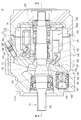
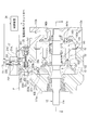
- FIGS. 2 and 3 show a hydraulic pump 10 according to a first embodiment of the present invention.
- 3 is a cross-sectional view taken along the line III-III in FIG. 2
- FIG. 2 is a cross-sectional view taken along the line II-II in FIG.
- the hydraulic pump 10 includes a housing 11 and a rotating shaft 12.
- the housing 11 includes a housing body 111 and a housing cap 112, both of which are fastened by bolts (not shown).
- the rotary shaft 12 passing through the internal space of the housing 11 is rotatably supported by the housing body 111 via the bearing 121 and is also rotatably supported by the housing cap 112 via the bearing 122.
- One end of the rotary shaft 12 constitutes a drive end 12 a driven by the output of the engine, and protrudes outward from the proximal end wall 111 a of the housing body 111.
- the swash plate 13 and the cylinder block 14 are disposed on the outer periphery of the rotation shaft 12.
- the swash plate 13 is a plate-like member in which a through hole 131 is formed at the center.
- the swash plate 13 is attached to the proximal end wall 111 a of the housing main body 111 via a pair of ball retainers (supports) 132 in a state where the rotary shaft 12 is inserted into the through hole 131.
- the swash plate 13 can be tilted relative to the housing 11 and the rotating shaft 12 with the ball retainer 132 as a fulcrum.
- a first sliding surface 133 is formed on the housing cap 112 side, and a second sliding surface 134 is formed on the housing body 111 side.
- the first sliding surface 133 is a flat surface in contact with a piston shoe described later, and is annularly formed around the through hole 131.
- the second sliding surface 134 is a flat surface that contacts a servo piston shoe described later, and is formed at a portion facing the servo piston shoe.
- the cylinder block 14 is a cylindrical member in which a through hole 141 for the rotation shaft 12 is formed at the center.
- the cylinder block 14 is coupled to the rotation shaft 12 by splines formed in the through holes 141 and rotates with the rotation shaft 12.
- the end of the cylinder block 14 on the housing cap 112 side is in contact with the inner wall surface of the housing cap 112 via the valve plate 142.
- the valve plate 142 is a plate-like member in which the suction port 142 a and the discharge port 142 b are formed, and is fixed to the housing cap 112.
- the suction port 142 a of the valve plate 142 communicates with the suction passage 112 a formed in the housing cap 112, and the discharge port 142 b communicates with the discharge passage 112 b formed in the housing cap 112.
- a plurality of cylinders 143 are formed in the cylinder block 14.
- the cylinders 143 are annularly arranged around the rotation axis 12.
- a communication port 143 a penetrating to the end face of the cylinder block 14 is formed on the valve plate 142 side of the cylinder 143.
- the communication port 143a of each cylinder 143 alternately communicates with the suction port 142a and the discharge port 142b by fixing the valve plate 142 to the housing cap 112 while the cylinder block 14 rotates with the rotary shaft 12. It will be.
- a piston 151 is slidably inserted into the cylinder 143 from the swash plate 13 side.
- a piston shoe 153 is connected to the swash plate 13 side of the piston 151 via a ball joint 152.
- the pressing force of the pressing spring 144 whose one end is fixed to the cylinder block 14 is transmitted through the rod 145, the retainer guide 146, and the pressing plate 147, so that the piston shoe 153 acts as a first slide of the swash plate 13.
- the moving surface 133 is abutted.
- the piston 151 is pulled out of the cylinder 143 while the cylinder 143 is in communication with the suction passage 112a, and the piston 151 is pushed into the cylinder 143 while the cylinder 143 is in communication with the discharge passage 112b.
- the oil sucked from the suction passage 112a is discharged to the discharge passage 112b.
- the discharge amount of oil is determined by the tilt angle of the swash plate 13. As the tilt angle becomes larger, the stroke of the piston 151 with respect to the cylinder 143 becomes larger, and the oil discharge amount increases. On the other hand, if the tilt angle of the swash plate 13 becomes smaller, the stroke of the piston 151 with respect to the cylinder 143 becomes smaller, and the amount of discharged oil decreases. When the tilt angle is 0 and the swash plate 13 is perpendicular to the rotating shaft 12, the stroke of the piston 151 is 0 and oil is not discharged.
- the tilt angle of the swash plate 13 is adjusted by operating the servo piston 161 shown in FIG.
- the servo piston 161 is slidably supported inside a servo sleeve 162 fixed to the housing main body 111, and one end thereof is connected to the servo piston shoe 164 via a ball joint 163.
- the pressing force of the spring 165 disposed between the housing main body 111 and the servo piston 161 is transmitted to the servo piston shoe 164 via the servo piston 161 and the ball joint 163, so that the servo piston shoe 164
- the second sliding surface 134 is abutted. Therefore, as described later, by controlling the pressure of the oil supplied to the pressure receiving chamber 166 of the servo piston 161, the tilt angle of the swash plate 13 can be adjusted.
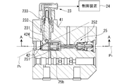
- FIG. 3 shows a tilting state detection unit provided to the hydraulic pump 10.
- the tilt state indicates an angle, a position, an attitude, and the like.
- the tilt state detection unit includes a lever 22 and a stroke sensor 23 supported by the housing 21, and a control device 24.
- the housing 21 includes a servo valve housing 21a and a stroke sensor housing 21b.
- the lever 22 indirectly contacts the swash plate 13 via the ball 221.
- the ball 221 is fitted in the recess 135 formed at the end of the swash plate 13 and moves in accordance with the displacement generated at the end of the swash plate 13 by the tilting of the swash plate 13.
- Control device 24 includes an operation unit that calculates the tilt angle of swash plate 13 based on the output signal of stroke sensor 23.
- the lever 22 has a first arm 223 and a second arm 224.
- the first arm 223 extends from the pivot shaft 222 downward in the figure, ie from the cavity in the servo valve housing 21a to the cavity in the housing body 111 of the hydraulic pump 10, Contact the ball 221 at the contact point 223a provided at the end.
- the servo valve 25 abuts on the servo valve contact portion 223b.
- the servo valve 25 has a spring box 251 that presses the servo valve 25 against the servo valve contact portion 223 b with a spring 25 b.
- the second arm portion 224 extends from the pivot shaft 222 in the right direction in the figure, that is, in a direction different from the first arm portion 223.
- the contactor 231 of the stroke sensor 23 abuts on the measuring portion 224a.
- the lever 22 is disposed on a first plane (plane parallel to the paper surface in FIG. 3) perpendicular to the pivot shaft 222 and is shown in FIG. 3 as a second plane orthogonal to the first plane.
- the contactor 231 and the spring box 251 are attached in such a direction that a moment is applied in the same direction around the pivot shaft 222 of the lever 22. Specifically, the contactor 231 and the spring box 251 are attached in such a direction as to generate a clockwise moment in the drawing about the pivot shaft 222.
- the stroke sensor 23 is, for example, a contact-type stroke sensor, and generates an output signal according to the displacement of the contactor 231 in the direction along the shaft 232.
- the stroke sensor 23 has a spring 233 that presses the contact 231 against the measurement portion 224 a of the lever 22.
- the stroke sensor 23 moves the lever 22 Specifically, it can be said that the amount of rotation is detected.
- FIG. 4 is a hydraulic circuit diagram showing a servo mechanism of the hydraulic pump 10 shown in FIG. 2 and FIG.
- pressure receiving chamber 166 of servo piston 161 includes a large diameter pressure receiving chamber 166a and a small diameter pressure receiving chamber 166b.
- the large diameter pressure receiving chamber 166 a is connected to the discharge passage 112 b of the hydraulic pump 10 via the servo valve 25.
- the small diameter pressure receiving chamber 166 b is connected to the discharge passage 112 b without the intervention of the servo valve 25.
- the servo valve 25 is a directional control valve of three ports and two positions, and contacts the pressure of oil supplied from the discharge passage 112 b of the hydraulic pump 10 to the hydraulic pilot 25 a and the lever 22 via the spring box 251.
- the spool 252 is switched between the communication position and the drain position by the balance with the biasing force of the spring 25b.
- the large diameter pressure receiving chamber 166a of the servo piston 161 communicates with the discharge passage 112b.
- the large diameter pressure receiving chamber 166a is shut off from the discharge passage 112b and communicated with the tank.
- the servo valve 25 when the servo valve 25 is in the communication position, the oil is supplied to the large diameter pressure receiving chamber 166a, so the servo piston 161 moves in the direction to reduce the tilt angle of the swash plate 13.
- the lever 22 pivots to the right in FIG. 4, that is, in the direction in which the spring 25b is compressed.
- the biasing force of the spring 25b increases, and the servo valve 25 switches to the drain position.
- oil is discharged from the large diameter pressure receiving chamber 166a, while oil is continuously supplied to the small diameter pressure receiving chamber 166b, so the servo piston 161 moves in a direction to increase the tilt angle of the swash plate 13. .
- the servo valve 25 when the discharge pressure of the hydraulic pump 10 is increased due to the load pressure rising in the work machine 3, the servo valve 25 is not switched to the drain position unless the lever 22 compresses the spring 25b to a large extent. Thus, in this case, the tilt angle is maintained at a smaller angle than before the discharge pressure is increased.
- the servo valve 25 when the discharge pressure of the hydraulic pump 10 is reduced, the servo valve 25 is switched to the drain position only by the lever 22 compressing the spring 25 b to a small degree. Thus, in this case, the tilt angle is maintained at a larger angle than before the discharge pressure drops.
- the servo valve 25 and the servo piston 161 make constant the product (horsepower) of the discharge amount of the hydraulic pump 10 determined by the tilt angle of the swash plate 13 and the discharge pressure determined by the load pressure. maintain.
- the pressure receiving chamber 166 of the servo piston 161 includes an additional pressure receiving chamber in addition to the large diameter pressure receiving chamber 166a and the small diameter pressure receiving chamber 166b, and the oil supplied to the additional pressure receiving chamber
- the pressure of the valve is controlled by an electromagnetic proportional pilot valve.
- the control device 24 calculates the tilt angle of the swash plate 13 based on the output signal of the stroke sensor 23, and generates the control signal generated based on the calculated tilt angle to the above-mentioned electromagnetic proportional pilot valve. input.
- the tilt angle of the swash plate 13 set for the same discharge pressure of the hydraulic pump 10 is changed, resulting in the hydraulic pressure
- the horsepower of the pump 10 can be adjusted.
- FIG. 5 shows a block diagram of the control device 24 of the hydraulic pump 10 shown in FIG. 2 and FIG.
- the control device 24 includes a tilt angle calculation unit 241, an angle difference calculation unit 242, a control signal generation unit 243, a control signal output unit 244, and a memory 245.
- the tilt angle calculation unit 241 calculates the tilt angle of the swash plate 13 based on the output signal of the stroke sensor 23. Specifically, the tilt angle calculation unit 241 sets the rotation angle of the lever 22 based on the displacement of the contactor 231 indicated by the output signal of the stroke sensor 23 and the distance between the measurement unit 224a and the rotation shaft 222. calculate. Further, the tilt angle calculation unit 241 is based on the distance between the contact point 223 a of the lever 22 and the pivot shaft 222 and the relative positional relationship between the ball 221 and the tilt shaft of the swash plate 13. Calculate the tilt angle of.
- the angle difference calculation unit 242 determines the tilt angle of the control target determined based on the state of the engine that drives the hydraulic pump 10 and the operation amount of the operation lever or pedal disposed in the cab 6, etc. A difference from the tilt angle of the swash plate 13 calculated by the rotation angle calculation unit 241 is calculated.
- the angle difference calculation unit 242 refers to data such as a control pattern stored in the memory 245 in determining the angle of the control target.
- the control signal generation unit 243 generates a control signal based on the difference of the angle calculated by the angle difference calculation unit 242.
- the control signal output unit 244 converts the control signal generated by the control signal generation unit 243 into a current value and a voltage value, and outputs the current signal and the voltage value to the above-described electromagnetic proportional pilot valve associated with the servo piston 161.
- the displacement generated at the end of the swash plate 13 by tilting is converted to the rotation of the lever 22 that abuts on the swash plate 13 via the ball 221, and the rotation of the lever 22 is performed.
- the tilt angle of the swash plate 13 is calculated based on the amount of movement. Since displacement due to tilting occurs anywhere except at the tilting axis of the swash plate 13, instead of the end of the swash plate 13 as in the above example, the lever 22 is brought into contact with various sites. It is possible to detect a displacement.
- the tilt angle of the swash plate 13 can also be detected by bringing the contact 231 of the stroke sensor 23 into contact with the swash plate 13 without the intervention of the lever 22.
- the contact 231 of the stroke sensor 23 is brought into contact with the lever 22 which is a separate member from the swash plate 13 to reduce the influence of micro-vibration and detect the tilt angle with high accuracy. It is possible.
- the displacement of the contact 231 differs depending on the distance between the position at which the contact 231 is in contact with the lever 22 and the rotation shaft 222. Specifically, the displacement is small if the position at which the contactor 231 abuts is close to the pivot shaft 222, and the displacement is large if it is far.
- the resolution of the detection value of the stroke sensor 23 can be changed by adjusting the position of bringing the contactor 231 into contact with the lever 22 by utilizing this.
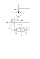
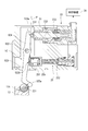
- FIGS. 6A and 6B show a tilt state detection unit of a hydraulic pump according to a second embodiment of the present invention.
- 6B is a cross-sectional view taken along the line BB of FIG. 6A
- FIG. 6A is a cross-sectional view taken along the line AA of FIG. 6B.
- the tilt state detection unit includes the lever 42 and the stroke sensor 23 accommodated in the housing 41, and the control device 24. The lever 42 contacts the swash plate 13 via the ball 221.
- the lever 42 is disposed on a first plane P 1 perpendicular to the pivot shaft 422 and is rotatably supported about the pivot shaft 422, and the spring of the stroke sensor 23 and the servo valve 25 is It is made to contact the ball 221 by the biasing force of
- the lever 42 has a single arm 423.
- the arm portion 423 extends from the pivot shaft 422 downward in FIG. 6A, that is, from the cavity in the housing 41 to the cavity in the housing of the hydraulic pump, and contacts the ball 221 at the contact point 423a provided at the end. Contact.
- the inclined surface 424 is an example of a measurement unit measured by the stroke sensor 23. That is, in this embodiment, the lever 42 has a measuring portion to the second upper plane P 2 that oblique to the first plane P 1 perpendicular to the rotation axis 422.
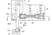
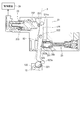
- FIG. 7 shows a tilt state detection unit of a hydraulic pump according to a third embodiment of the present invention.
- the tilt state detection unit includes the lever 52 and the stroke sensor 23 accommodated in the housing 51, and the control device 24.
- the lever 52 contacts the swash plate 13 via the ball 221.
- the lever 52 is rotatably supported around the rotation shaft 522 and is brought into contact with the ball 221 by the biasing force of the spring of the servo valve 25.
- the lever 52 has a first arm 523 and a second arm 524.
- the first arm 523 extends from the rotation shaft 522 downward in the figure, that is, from the hollow portion in the housing 51 to the hollow portion in the housing of the hydraulic pump, and the ball 221 at the contact point 523a provided at the end.
- Contact The spring box 251 of the servo valve 25 abuts on the servo valve contact portion 523 b of the first arm 523.
- the second arm 524 extends upward from the pivot shaft 522 in the figure.
- the contact 231 of the stroke sensor 23 is in contact with the measurement portion 524 a of the second arm 524.
- the lever 52 is disposed on a first plane (plane parallel to the paper surface in FIG. 7) perpendicular to the pivot shaft 522, and is shown in FIG. 7 as a second plane orthogonal to the first plane. And a measuring unit 524a on the plane P).
- the tilt state detection unit becomes more compact in the height direction in the drawing.
- the present embodiment has the same configuration as that of the above first embodiment with respect to the configuration other than the above, the duplicated description will be omitted.
- FIG. 8 shows a tilt state detection unit of a hydraulic pump according to a fourth embodiment of the present invention.
- the tilt state detection unit includes the lever 52 and the stroke sensor 23 accommodated in the housing 61, and the control device 24.
- the stroke sensor 23 and the servo valve 25 are attached in a direction in which a moment is applied in the same direction around the pivot shaft 522 of the lever 52.
- the lever 52 is disposed on a first plane (a plane parallel to the paper surface in FIG. 8) perpendicular to the pivot shaft 522, and a second plane (shown in FIG. 8) perpendicular to the first plane.
- the present embodiment has the same configuration as that of the above-described third embodiment with respect to the configuration other than the above, the duplicated description will be omitted.
- the stroke sensor 23 can be disposed in various directions or in various directions with respect to the hydraulic pump 10.
- the arrangement of the stroke sensor 23 can be changed in accordance with the shape of the available space around the hydraulic pump 10, or the direction in which the existing hydraulic pump 10 can be additionally installed when the stroke sensor 23 is arranged Or you can choose the orientation.
- the tilt angle of the swash plate may be similarly detected by a variable displacement hydraulic motor using the swash plate.
- the tilt angle of the oblique shaft may be detected in the same manner with a variable displacement hydraulic pump or hydraulic motor using the oblique shaft.
- the working fluid of the hydraulic pump or motor is not limited to oil, and may be another type of fluid.
- the lever indirectly contacts the swash plate via the ball, but in another embodiment, the lever directly contacts the swash plate without the ball. May be Also, the lever may contact the swash plate indirectly through one or more members other than the ball.
- the pivoting amount of the lever is detected using a stroke sensor which is a contact type displacement meter, but in another embodiment, the pivoting amount of the lever using a non-contact type displacement meter May be detected.
- the rotation amount of the lever may be detected from the rotation angle using a rotary encoder or the like arranged in the vicinity of the rotary shaft of the lever.
- the tilt angle of the swash plate is changed using a hydraulically driven servo piston, but in the other embodiments, a drive means that does not use oil pressure is used to change the swash plate.
- the tilt angle may be changed.
- a proportional solenoid valve instead of the servo piston, a proportional solenoid valve may be arranged. In this case, no servo valve is required, and the control signal generated in the controller is input to the proportional solenoid valve.
- the hydraulic pump for driving the work machine of the wheel loader has been described as an example, but the hydraulic rotating device according to the other embodiments is other than hydraulic shovel, bulldozer, forklift
- the present invention is also applicable to work machines.
Landscapes
- Engineering & Computer Science (AREA)
- Mechanical Engineering (AREA)
- General Engineering & Computer Science (AREA)
- Reciprocating Pumps (AREA)
- Control Of Positive-Displacement Pumps (AREA)
- Hydraulic Motors (AREA)
Priority Applications (3)
| Application Number | Priority Date | Filing Date | Title |
|---|---|---|---|
| DE112018003195.0T DE112018003195T5 (de) | 2017-06-22 | 2018-06-04 | Hydraulikpumpe und -motor |
| US16/484,921 US11293417B2 (en) | 2017-06-22 | 2018-06-04 | Hydraulic pump and motor |
| CN201880011913.XA CN110312867B (zh) | 2017-06-22 | 2018-06-04 | 液压泵及马达 |
Applications Claiming Priority (2)
| Application Number | Priority Date | Filing Date | Title |
|---|---|---|---|
| JP2017122348A JP6913527B2 (ja) | 2017-06-22 | 2017-06-22 | 油圧ポンプおよびモータ |
| JP2017-122348 | 2017-06-22 |
Publications (1)
| Publication Number | Publication Date |
|---|---|
| WO2018235573A1 true WO2018235573A1 (ja) | 2018-12-27 |
Family
ID=64737757
Family Applications (1)
| Application Number | Title | Priority Date | Filing Date |
|---|---|---|---|
| PCT/JP2018/021308 Ceased WO2018235573A1 (ja) | 2017-06-22 | 2018-06-04 | 油圧ポンプおよびモータ |
Country Status (5)
| Country | Link |
|---|---|
| US (1) | US11293417B2 (enExample) |
| JP (1) | JP6913527B2 (enExample) |
| CN (1) | CN110312867B (enExample) |
| DE (1) | DE112018003195T5 (enExample) |
| WO (1) | WO2018235573A1 (enExample) |
Cited By (1)
| Publication number | Priority date | Publication date | Assignee | Title |
|---|---|---|---|---|
| CN111173699A (zh) * | 2020-02-18 | 2020-05-19 | 华中科技大学无锡研究院 | 带压力保护水介质斜盘式轴向柱塞泵 |
Families Citing this family (5)
| Publication number | Priority date | Publication date | Assignee | Title |
|---|---|---|---|---|
| AU2018386193B2 (en) | 2017-12-13 | 2025-04-24 | Momenta Pharmaceuticals, Inc. | FcRn antibodies and methods of use thereof |
| JP2020183744A (ja) * | 2019-05-09 | 2020-11-12 | ナブテスコ株式会社 | 油圧ポンプ及び建設機械 |
| DE102020210397B3 (de) * | 2020-08-14 | 2021-10-14 | Danfoss Power Solutions Gmbh & Co. Ohg | Hydrostatische servoeinheit |
| KR102746290B1 (ko) * | 2021-07-16 | 2024-12-26 | 두산모트롤 주식회사 | 유압펌프의 고장 진단 장치 |
| US12331740B2 (en) | 2022-12-05 | 2025-06-17 | Hamilton Sundstrand Corporation | Variable displacement pumps |
Citations (3)
| Publication number | Priority date | Publication date | Assignee | Title |
|---|---|---|---|---|
| JPS5265305U (enExample) * | 1975-11-10 | 1977-05-14 | ||
| JPH0482378U (enExample) * | 1990-11-29 | 1992-07-17 | ||
| JP2002106460A (ja) * | 2000-09-28 | 2002-04-10 | Komatsu Ltd | 可変容量型流体機械の容量制御装置 |
Family Cites Families (17)
| Publication number | Priority date | Publication date | Assignee | Title |
|---|---|---|---|---|
| DE1653385C3 (de) * | 1967-08-25 | 1980-07-24 | Volvo Hydraulikfabrik Gmbh, 1000 Berlin | Vorrichtung zum Konstanthalten des Produktes aus Druck und Hubvolumen bei einer Verdrängerpumpe |
| IT1049748B (it) | 1975-11-24 | 1981-02-10 | Rocchitelli Onofrio | Pompa elettromagnetica lavavetri particolarmente per vetri para brezza di autoveicoli |
| DE3208250A1 (de) * | 1982-03-08 | 1983-09-15 | Robert Bosch Gmbh, 7000 Stuttgart | Einrichtung zum steuern und/oder regeln einer axialkolbenmaschine |
| DD247044A1 (de) | 1986-02-28 | 1987-06-24 | Ind Werke Veb | Mechanische rueckfuehrung fuer eine elektrohydraulische stelleinrichtung |
| JP3089021B2 (ja) | 1990-07-24 | 2000-09-18 | 株式会社東芝 | 垂直偏向用鋸歯状波発生回路 |
| KR950007252B1 (ko) * | 1991-11-30 | 1995-07-07 | 삼성중공업주식회사 | 가변용량형 유압펌프의 제어장치 |
| KR950003064B1 (ko) * | 1992-05-30 | 1995-03-30 | 삼성중공업 주식회사 | 가변용량형 유압펌프의 제어장치 |
| JPH07180655A (ja) * | 1993-12-22 | 1995-07-18 | Hitachi Constr Mach Co Ltd | 容量可変型斜軸式液圧回転機 |
| JPH1137042A (ja) | 1997-07-14 | 1999-02-09 | Hitachi Constr Mach Co Ltd | 可変容量型斜板式油圧ポンプ |
| JPH11257209A (ja) | 1998-03-16 | 1999-09-21 | Yuken Kogyo Co Ltd | モータ一体型油圧ポンプ装置 |
| DE10063525B4 (de) | 2000-12-20 | 2005-07-07 | Brueninghaus Hydromatik Gmbh | Verstellvorrichtung zum Verstellen eines auf das Verdrängungsvolumen einer hydrostatischen Maschine einwirkenden Stellkolbens |
| WO2006129431A1 (ja) | 2005-05-30 | 2006-12-07 | Hitachi Construction Machinery Co., Ltd. | 可変容量型斜板式液圧回転機 |
| US7469534B2 (en) * | 2005-09-26 | 2008-12-30 | Kubota Corporation | Load control structure for work vehicle |
| CN101372941B (zh) * | 2008-09-18 | 2011-09-14 | 联塑(杭州)机械有限公司 | 一种轴向柱塞式变量泵 |
| US8661804B2 (en) | 2009-12-11 | 2014-03-04 | Caterpillar Inc. | Control system for swashplate pump |
| JP4934749B1 (ja) | 2011-02-23 | 2012-05-16 | 株式会社小松製作所 | 可変容量型油圧ポンプ・モータ |
| EP3045723B1 (de) | 2015-01-16 | 2019-04-10 | HAWE Hydraulik SE | Axialkolbenpumpe |
-
2017
- 2017-06-22 JP JP2017122348A patent/JP6913527B2/ja active Active
-
2018
- 2018-06-04 DE DE112018003195.0T patent/DE112018003195T5/de active Pending
- 2018-06-04 CN CN201880011913.XA patent/CN110312867B/zh active Active
- 2018-06-04 US US16/484,921 patent/US11293417B2/en active Active
- 2018-06-04 WO PCT/JP2018/021308 patent/WO2018235573A1/ja not_active Ceased
Patent Citations (3)
| Publication number | Priority date | Publication date | Assignee | Title |
|---|---|---|---|---|
| JPS5265305U (enExample) * | 1975-11-10 | 1977-05-14 | ||
| JPH0482378U (enExample) * | 1990-11-29 | 1992-07-17 | ||
| JP2002106460A (ja) * | 2000-09-28 | 2002-04-10 | Komatsu Ltd | 可変容量型流体機械の容量制御装置 |
Cited By (1)
| Publication number | Priority date | Publication date | Assignee | Title |
|---|---|---|---|---|
| CN111173699A (zh) * | 2020-02-18 | 2020-05-19 | 华中科技大学无锡研究院 | 带压力保护水介质斜盘式轴向柱塞泵 |
Also Published As
| Publication number | Publication date |
|---|---|
| US20200003191A1 (en) | 2020-01-02 |
| JP2019007387A (ja) | 2019-01-17 |
| CN110312867B (zh) | 2021-11-09 |
| JP6913527B2 (ja) | 2021-08-04 |
| US11293417B2 (en) | 2022-04-05 |
| CN110312867A (zh) | 2019-10-08 |
| DE112018003195T5 (de) | 2020-03-05 |
Similar Documents
| Publication | Publication Date | Title |
|---|---|---|
| WO2018235573A1 (ja) | 油圧ポンプおよびモータ | |
| CN110914547B (zh) | 液压驱动装置 | |
| JP5188444B2 (ja) | 作業機の液圧駆動装置 | |
| US6435289B1 (en) | Apparatus for altering operation apparatus and actuator combinations, and operation lever apparatus | |
| CN108698636A (zh) | 作业车辆及作业车辆的控制方法 | |
| US20230136445A1 (en) | Servoless motor | |
| JP7085996B2 (ja) | 作業機械および作業機械の制御方法 | |
| JPH102279A (ja) | 可変容量形ポンプアセンブリ | |
| US7243492B2 (en) | Inclined rotation control device of variable displacement hydraulic pump | |
| JP5204531B2 (ja) | サーボレギュレータ | |
| JP2005320912A (ja) | 可変容量型油圧ポンプ | |
| KR20200125429A (ko) | 가변 용량형 유압 펌프 및 건설 기계 | |
| JP5771119B2 (ja) | 作業車 | |
| EP1760313A1 (en) | Variable displacement swash plate-type hydraulic rotating machine | |
| US20040101417A1 (en) | Volume control apparatus of radial piston pump or motor and positioning apparatus | |
| CN118525145A (zh) | 液压旋转机械及液压泵 | |
| WO2022210981A1 (ja) | 作業機械及び作業機械用の操作装置 | |
| JP5060213B2 (ja) | サーボレギュレータ | |
| JP2005201076A (ja) | 可変容量型油圧ポンプの傾転制御装置 | |
| JP2021173246A (ja) | 流体圧駆動装置 | |
| JP2009243409A (ja) | サーボレギュレータ | |
| JP5858893B2 (ja) | 複動型油圧シリンダの操作構造 | |
| JP2005201301A (ja) | 可変容量型油圧ポンプの傾転制御装置 | |
| KR20170006842A (ko) | 건설기계의 제어 시스템 및 이를 이용한 건설기계의 제어 방법 | |
| JP2005194916A (ja) | 可変容量型油圧ポンプの傾転制御装置 |
Legal Events
| Date | Code | Title | Description |
|---|---|---|---|
| 121 | Ep: the epo has been informed by wipo that ep was designated in this application |
Ref document number: 18820290 Country of ref document: EP Kind code of ref document: A1 |
|
| 122 | Ep: pct application non-entry in european phase |
Ref document number: 18820290 Country of ref document: EP Kind code of ref document: A1 |