WO2018235546A1 - キャパシタ用電極箔及びキャパシタ - Google Patents
キャパシタ用電極箔及びキャパシタ Download PDFInfo
- Publication number
- WO2018235546A1 WO2018235546A1 PCT/JP2018/020610 JP2018020610W WO2018235546A1 WO 2018235546 A1 WO2018235546 A1 WO 2018235546A1 JP 2018020610 W JP2018020610 W JP 2018020610W WO 2018235546 A1 WO2018235546 A1 WO 2018235546A1
- Authority
- WO
- WIPO (PCT)
- Prior art keywords
- capacitor
- electrode
- electrode foil
- active material
- foil
- Prior art date
- Legal status (The legal status is an assumption and is not a legal conclusion. Google has not performed a legal analysis and makes no representation as to the accuracy of the status listed.)
- Ceased
Links
Images


Classifications
-
- H—ELECTRICITY
- H01—ELECTRIC ELEMENTS
- H01G—CAPACITORS; CAPACITORS, RECTIFIERS, DETECTORS, SWITCHING DEVICES, LIGHT-SENSITIVE OR TEMPERATURE-SENSITIVE DEVICES OF THE ELECTROLYTIC TYPE
- H01G11/00—Hybrid capacitors, i.e. capacitors having different positive and negative electrodes; Electric double-layer [EDL] capacitors; Processes for the manufacture thereof or of parts thereof
- H01G11/22—Electrodes
- H01G11/26—Electrodes characterised by their structure, e.g. multi-layered, porosity or surface features
- H01G11/28—Electrodes characterised by their structure, e.g. multi-layered, porosity or surface features arranged or disposed on a current collector; Layers or phases between electrodes and current collectors, e.g. adhesives
-
- H—ELECTRICITY
- H01—ELECTRIC ELEMENTS
- H01G—CAPACITORS; CAPACITORS, RECTIFIERS, DETECTORS, SWITCHING DEVICES, LIGHT-SENSITIVE OR TEMPERATURE-SENSITIVE DEVICES OF THE ELECTROLYTIC TYPE
- H01G11/00—Hybrid capacitors, i.e. capacitors having different positive and negative electrodes; Electric double-layer [EDL] capacitors; Processes for the manufacture thereof or of parts thereof
- H01G11/04—Hybrid capacitors
- H01G11/06—Hybrid capacitors with one of the electrodes allowing ions to be reversibly doped thereinto, e.g. lithium ion capacitors [LIC]
-
- H—ELECTRICITY
- H01—ELECTRIC ELEMENTS
- H01G—CAPACITORS; CAPACITORS, RECTIFIERS, DETECTORS, SWITCHING DEVICES, LIGHT-SENSITIVE OR TEMPERATURE-SENSITIVE DEVICES OF THE ELECTROLYTIC TYPE
- H01G11/00—Hybrid capacitors, i.e. capacitors having different positive and negative electrodes; Electric double-layer [EDL] capacitors; Processes for the manufacture thereof or of parts thereof
- H01G11/22—Electrodes
-
- H—ELECTRICITY
- H01—ELECTRIC ELEMENTS
- H01G—CAPACITORS; CAPACITORS, RECTIFIERS, DETECTORS, SWITCHING DEVICES, LIGHT-SENSITIVE OR TEMPERATURE-SENSITIVE DEVICES OF THE ELECTROLYTIC TYPE
- H01G11/00—Hybrid capacitors, i.e. capacitors having different positive and negative electrodes; Electric double-layer [EDL] capacitors; Processes for the manufacture thereof or of parts thereof
- H01G11/22—Electrodes
- H01G11/26—Electrodes characterised by their structure, e.g. multi-layered, porosity or surface features
-
- H—ELECTRICITY
- H01—ELECTRIC ELEMENTS
- H01G—CAPACITORS; CAPACITORS, RECTIFIERS, DETECTORS, SWITCHING DEVICES, LIGHT-SENSITIVE OR TEMPERATURE-SENSITIVE DEVICES OF THE ELECTROLYTIC TYPE
- H01G11/00—Hybrid capacitors, i.e. capacitors having different positive and negative electrodes; Electric double-layer [EDL] capacitors; Processes for the manufacture thereof or of parts thereof
- H01G11/22—Electrodes
- H01G11/30—Electrodes characterised by their material
- H01G11/50—Electrodes characterised by their material specially adapted for lithium-ion capacitors, e.g. for lithium-doping or for intercalation
-
- H—ELECTRICITY
- H01—ELECTRIC ELEMENTS
- H01G—CAPACITORS; CAPACITORS, RECTIFIERS, DETECTORS, SWITCHING DEVICES, LIGHT-SENSITIVE OR TEMPERATURE-SENSITIVE DEVICES OF THE ELECTROLYTIC TYPE
- H01G11/00—Hybrid capacitors, i.e. capacitors having different positive and negative electrodes; Electric double-layer [EDL] capacitors; Processes for the manufacture thereof or of parts thereof
- H01G11/54—Electrolytes
- H01G11/58—Liquid electrolytes
- H01G11/62—Liquid electrolytes characterised by the solute, e.g. salts, anions or cations therein
-
- H—ELECTRICITY
- H01—ELECTRIC ELEMENTS
- H01G—CAPACITORS; CAPACITORS, RECTIFIERS, DETECTORS, SWITCHING DEVICES, LIGHT-SENSITIVE OR TEMPERATURE-SENSITIVE DEVICES OF THE ELECTROLYTIC TYPE
- H01G11/00—Hybrid capacitors, i.e. capacitors having different positive and negative electrodes; Electric double-layer [EDL] capacitors; Processes for the manufacture thereof or of parts thereof
- H01G11/78—Cases; Housings; Encapsulations; Mountings
-
- Y—GENERAL TAGGING OF NEW TECHNOLOGICAL DEVELOPMENTS; GENERAL TAGGING OF CROSS-SECTIONAL TECHNOLOGIES SPANNING OVER SEVERAL SECTIONS OF THE IPC; TECHNICAL SUBJECTS COVERED BY FORMER USPC CROSS-REFERENCE ART COLLECTIONS [XRACs] AND DIGESTS
- Y02—TECHNOLOGIES OR APPLICATIONS FOR MITIGATION OR ADAPTATION AGAINST CLIMATE CHANGE
- Y02E—REDUCTION OF GREENHOUSE GAS [GHG] EMISSIONS, RELATED TO ENERGY GENERATION, TRANSMISSION OR DISTRIBUTION
- Y02E60/00—Enabling technologies; Technologies with a potential or indirect contribution to GHG emissions mitigation
- Y02E60/13—Energy storage using capacitors
Definitions
- the present invention relates to an electrode foil for a capacitor and a capacitor provided with an electrode active material layer such as a polarizable electrode.
- An electric double layer capacitor is configured by filling an electrolyte between a pair of polarizable electrodes.
- the hybrid capacitor includes a polarizable electrode on the positive electrode side, and a layer of metal compound particles or a carbon material capable of inserting and extracting lithium ions on the negative electrode side. Both the electric double layer capacitor and the hybrid capacitor use the storage effect of the electric double layer formed at the interface between the polarizable electrode and the electrolyte.
- the negative electrode of the hybrid capacitor is a Faraday reaction electrode.
- the capacitor having the polarizable electrode When the capacitor having the polarizable electrode is charged, charged particles are aligned at the interface between the polarizable electrode and the electrolyte.
- the anions of the electrolyte are aligned at the interface with the polarizable electrode and form pairs with the holes in the polarizable electrode at a very short distance. Thereby, a potential barrier is formed on the positive electrode.
- the cation of the electrolyte is also aligned at the interface with the polarizable electrode even at the negative electrode, and pairs with electrons in the polarizable electrode at a very short distance to form a potential barrier at the negative electrode. Ru.
- the capacitor utilizing the electric double layer physically stores charge without utilizing chemical reaction for charging and discharging. Therefore, the capacitor using the electric double layer has less deterioration of the constituent material and is excellent in charge and discharge cycle life. Therefore, capacitors using an electric double layer are often employed for the purpose of reducing replacement frequency and maintenance-free in applications and installation places where regular parts replacement is difficult.
- this invention aims at providing the electrode foil for capacitors and capacitor in which deterioration of the capacity
- the present inventors produced two wound-type electric double layer capacitors, performed 40,000 charge and discharge cycle tests on the first electric double layer capacitor, and performed on the second electric double layer capacitor.
- the float test was performed for 5000 hours.
- ion concentration (M) of three places was quantified with respect to the polarizable electrode of the positive electrode side of the 1st and 2nd electric double layer capacitor, the polarizable electrode of the negative electrode side, and the separator, respectively.
- the ion concentration is any of cationic species or anionic species of the electrolytic solution, and varies depending on whether the place to be quantified is the positive electrode, the negative electrode, or the separator.
- the wound-type electric double layer capacitor has a cylindrical capacitor element.
- the cylindrical capacitor element is formed by superposing the positive electrode foil and the negative electrode foil with the separator interposed therebetween, and spirally winding around the winding axis to produce the cylindrical capacitor element.
- the electrode terminal portion is drawn out from one end surface of the cylindrical capacitor element.
- the area where the ion concentration (M) is determined is in the vicinity of the upper part of the cylinder axis (hereinafter referred to as the upper region) connected to the end face from which the electrode terminal part is drawn It is near the lower half of the cylinder axis (hereinafter, referred to as a lower region) connected to an end surface near the middle belly (hereinafter referred to as the middle belly region) and the end surface opposite to the end surface from which the electrode terminal portion is drawn.
- the results are shown in Table 1 below. The unit of each numerical value is M (mol / L).
- the concentration of ions in the upper region, the lower region, and the middle abdominal region is equal.
- the ion concentration in the upper and lower regions was lower than in the initial condition, and the ion concentration in the middle abdominal region was higher than the initial condition. That is, it was found that when charge and discharge were repeated, the ions moved from the upper area and the lower area to the middle area and the ion concentration gradient was generated inside the electric double layer capacitor.
- the float test no concentration gradient of ions was generated.
- the present inventors considered that when charge and discharge were repeated, a concentration gradient of ions was generated, and a sparse region of ions existed at the interface between the polarizable electrode and the electrolyte. It was considered that the capacity developed in the region where the ions are sparse was small, and as a result, the capacity of the entire capacitor was lowered.
- a capacitor electrode foil according to the present invention includes a current collector, an electrode active material layer formed on the surface of the current collector, and a dividing portion that divides the electrode active material layer into small regions. That is. If the electrode active material layer is divided into small regions, movement of ions between the small regions is suppressed, and the generation of concentration gradient of ions is suppressed.
- the electrode active material layer has a band shape, and the dividing portion extends in the longitudinal direction of the electrode active material layer, and divides the electrode active material layer into strip-like small regions extending along the longitudinal direction of the band. It may be a groove, and the small region may have a length in the band width direction along the direction orthogonal to the divided portion of 30 mm or more and 50 mm or less.
- the concentration gradient of ions that can occur in the same small region can be made gentle, and regions in which the volume is small can be further minimized.
- the electrode active material layer has a band shape, and the dividing portion extends in the longitudinal direction of the electrode active material layer, and divides the electrode active material layer into strip-like small regions extending along the longitudinal direction of the band. It may be a groove, and the width may be 1 mm or more. The movement of ions between the small regions is effectively suppressed, and the reduction of the surface area of the electrode active material layer is minimized.
- the electrode active material layer may have a band shape, and the divisions may extend along the band longitudinal direction of the electrode active material layer. It is possible to suppress the movement of ions from the upper area to the middle and lower area and from the lower to the middle area.
- a capacitor including such an electrode foil for a capacitor and an electrolytic solution is also an aspect of the present invention.
- an electric double layer capacitor having a polarizable electrode on both the positive electrode and the negative electrode, a hybrid electrode capacitor having a polarizable electrode on the positive electrode side and an electrode comprising a layer of metal compound particles absorbing and releasing lithium ions on the negative electrode side is also an aspect of the present invention.
- the capacitor electrode foil may be provided only on the positive electrode side.
- the electrode active material layer of the electrode foil on the positive electrode side is divided into small regions by the dividing portions, the difference in ion concentration is suppressed even in the electrode active material layer on the negative electrode side not having the dividing portions.
- at least the positive electrode side may be provided with the capacitor electrode foil, and both the positive electrode and the negative electrode may be provided with the capacitor electrode foil.
- the capacitor electrode foil having the divided portion on the positive electrode side may be provided, and the small region on the positive electrode side may be covered with the active material layer of the opposing negative electrode.
- the capacitor electrode foil having the divided portion on both the positive electrode and the negative electrode is provided, the width of the small region of the positive electrode is narrower than the width of the small region of the negative electrode, and the small region of the positive electrode is The small area of the opposite negative electrode may be covered. A non-facing region not directly facing the negative electrode electrode material on the positive electrode side can be eliminated, and capacity deterioration can be further suppressed.
- the capacitor electrode foil is wound via a separator, and a capacitor element containing an electrolytic solution, an outer case housing the capacitor element, and a side surface of the outer case are pressed to fix the capacitor element.
- the pressing portion may be formed at the position of the small area without coinciding with the position of the divided portion. Since the capacitor element is favorably captured by the pressing portion and the capacitor element does not become unstable in the outer case, the divided portion does not affect the vibration resistance.
- the present invention even if the capacitor is repeatedly charged and discharged, the deterioration of the capacitance is suppressed.
- FIG. 1 It is a figure which shows the structure of the positive electrode foil which concerns on this embodiment. It is a schematic diagram which shows the positional relationship of positive electrode foil and negative electrode foil. It is a schematic diagram which shows the state which crimped the capacitor. It is a schematic diagram which shows the quantification location of the ion concentration of Example 1 and Comparative Example 1.
- FIG. It is a graph which shows the ion concentration distribution of the electric double layer capacitor of Example 1 and Comparative Example 1.
- FIG. It is a graph which shows capacity
- the capacitor is provided with a layer of an electrode active material on a positive electrode foil and a negative electrode foil, and utilizes the storage effect of an electric double layer formed on the interface between the polarizable electrode of at least one of the positive electrode foil or the negative electrode foil and the electrolyte.
- this capacitor is an electric double layer capacitor or a hybrid capacitor.
- the electric double layer capacitor has polarizable electrodes on both the positive electrode foil and the negative electrode foil.
- the hybrid capacitor has a polarizable electrode on a positive electrode foil, and a layer of an electrode active material made of metal compound particles capable of inserting and extracting lithium ions on a negative electrode foil or a Faraday reaction electrode of a carbon material.
- the shape of the capacitor can be wound or laminated. Hereinafter, a wound capacitor will be exemplified.
- capacitors comprise a positive electrode foil, a negative electrode foil, a separator and an electrolyte.
- the positive electrode foil, the negative electrode foil and the separator have a band shape.
- the positive electrode foil and the negative electrode foil are superimposed on each other with the separator interposed therebetween, and are spirally wound so that the longitudinal direction of the band forms a circumference, and is formed into a cylindrical capacitor element.
- the capacitor element is impregnated with an electrolytic solution.
- the medium of the electrolytic solution may not be a liquid as long as it can hold the electrolyte, and may be a solid polymer or a gel electrolyte.
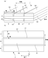
- FIG. 1 is a schematic view showing the electrode foil 1, (a) is a sectional perspective view, and (b) is a plan view.
- an electrode foil 1 to be a positive electrode foil and a negative electrode foil is formed by forming an electrode active material layer 3 such as a polarizable electrode or a faraday electrode on a current collector 7.
- the current collector 7 is a valve metal such as aluminum, platinum, gold, nickel, titanium and steel.
- the shape of the current collector 7 may be any shape such as a film shape, a foil shape, or a plate shape. Further, the surface of the current collector 7 may form an uneven surface by etching or the like, or may be a plain surface. Furthermore, surface treatment may be performed to attach phosphorus to the surface of the current collector 7.
- the electrode foil 1 is, for example, a carbon material having a porous structure having an electric double layer capacity or a fibrous structure, or an electrode material which is a material of the electrode active material layer 3 such as metal compound particles or a carbon material causing a faradaic reaction.
- the binder can be mixed with the mixture with the conductive aid, and after being kneaded, it can be formed into a sheet.
- a mixed solution of an electrode material, a conductive additive and a binder may be coated on the current collector 7 by a doctor blade method or the like and dried to form an electrode.
- the electrode foil 1 can also be formed by molding the obtained dispersion into a predetermined shape and pressing it on the current collector 7.
- the thickness of the electrode foil 1 is preferably 20 to 150 ⁇ m.
- binder for example, rubbers such as fluorine-based rubber, diene-based rubber and styrene-based rubber, fluorine-containing polymers such as polytetrafluoroethylene and polyvinylidene fluoride, celluloses such as carboxymethyl cellulose and nitrocellulose, others, polyolefin resin, polyimide Resin, acrylic resin, nitrile resin, polyester resin, phenol resin, polyvinyl acetate resin, polyvinyl alcohol resin, epoxy resin and the like can be mentioned. These binders may be used alone or in combination of two or more.
- the carbon nanotube may be a single-walled carbon nanotube (SWCNT) in which the graphene sheet is a single layer, or a multi-walled carbon nanotube (MWCNT) in which two or more graphene sheets are concentrically rounded and the tube wall is multi-layered. It may be done.
- SWCNT single-walled carbon nanotube
- MWCNT multi-walled carbon nanotube
- the material of the electrode active material layer 3 in the polarizable electrode is typically carbon powder. You may add a conductive support agent to carbon powder.
- the carbon powder may be subjected to activation treatment such as steam activation, alkali activation, zinc chloride activation or electric field activation, and opening treatment.
- Examples of carbon powder include natural plant tissue such as coconut palm, synthetic resin such as phenol, activated carbon derived from fossil fuel such as coal, coke and pitch, carbon such as ketjen black, acetylene black and channel black Black, carbon nanohorns, amorphous carbon, natural graphite, artificial graphite, graphitized ketjen black, activated carbon, mesoporous carbon and the like can be mentioned.
- the metal compound particle layer can occlude and release lithium ions, for example, FeO, Fe 2 O 3 , Fe 3 O 4 , MnO, MnO 2 , Mn 2 O 3 , Mn 3 O 4 , CoO, CoO 3 O 4, NiO, Ni 2 O 3, TiO, TiO 2, TiO 2 (B), CuO, NiO, SnO, SnO 2, SiO 2, RuO 2, WO, WO 2, WO 3, MoO 3, ZnO or the like Oxides, Sn, Si, Al, metals such as Zn, LiVO 2 , Li 3 VO 4 , Li 4 Ti 5 O 12 , Sc 2 TiO 5 , Fe 2 TiO 5 , LiFePO 4 , Li 3 V 2 (PO 4 ) 3 composite oxide such as, Li 2.6 Co 0.4 N, Ge 3 N 4, Zn 3 N 2, Cu 3 N nitrides such include Y 2 Ti 2
- the through hole penetrating the current collector 7 of the positive electrode foil and the electrode active material layer 3 is not provided, and the penetrating through the current collector 7 of the negative electrode foil and the carbon material layer It is desirable to have no holes.
- a carbon coat layer containing a conductive agent such as graphite may be provided between the current collector 7 and the electrode active material layer 3.
- a carbon coat layer can be formed by applying and drying a slurry containing a conductive agent such as graphite, a binder and the like on the surface of the current collector.
- a divided portion 31 extending in a straight line along one side of the electrode foil 1 is provided.
- the dividing portion 31 is a thin line region where the material of the electrode active material layer 3 does not exist from the surface of the layer of the electrode active material layer 3 to the bottom of the layer and the current collector 7 or the carbon coat layer is exposed.
- the material layer 3 is cut completely from end to end.
- the electrode active material layer 3 is divided into a plurality of strip-like small regions 32 at the dividing portion 31.
- the division unit 31 loses the connection between the small regions 32.
- the dividing portion 31 is a groove or a recess in which a single line or a plurality of lines extend in parallel.
- the electrode active material layer 3 is divided into two or more small regions 32 in accordance with the number of divisions 31.
- the divisions 31 are formed in two lines along the strip longitudinal direction of the positive electrode foil, and the small areas 32 are arranged in the direction orthogonal to the strip longitudinal direction, and are divided into the upper area U, the middle area M, and the lower area D in the cylinder axis direction. Divide and extend parallel to one another.
- the dividing portion 31 may be formed by not applying the slurry of the electrode active material layer 3 in advance to the region to be the dividing portion 31 or by not bonding the sheet of the electrode active material layer 3, and in addition, the current collector A part of the electrode active material layer 3 formed on 7 may be removed by a laser, a brush, or another mechanical method to form a divided portion.
- ions in the electrode active material layer 3 can not easily move between the small regions 32 by the dividing portion 31. Therefore, in the electrode active material layer 3, a concentration gradient of ions spreading in the direction orthogonal to the dividing portion 31 is suppressed. As a result, it becomes difficult to form a region with a low ion concentration in the electrode active material layer 3, and the capacitance deterioration of the capacitor 1 is suppressed.
- the width of the small area 32 of one line is narrower than the entire width of the electrode active material layer 3, it is difficult for the difference in concentration of ions to be attached even within the small area 32 of one line. Therefore, a region with a low ion concentration is less likely to occur even in one row of small regions 32, and the capacitance deterioration of the capacitor 1 is suppressed.
- the provision of the dividing portion 31 results in a capacity retention rate of about 90% (in Example 1, which will be described later, a decrease of 8% and a capacity retention rate of 92%).
- the capacity retention ratio of the capacitor 1 drops to about 80%, so that the dividing portion 31 is not provided when the total area Y of the small area 32 is Y. It exceeds the capacity of the capacitor where the capacity deterioration has occurred.
- the width of the small area 32 is desirably 20 mm or more and 50 mm or less.
- the electrode active material layer 3 of the positive electrode foil may be divided into the small regions 32 by the dividing portion 31.
- the electrode active material layer 3 of the negative electrode foil may also be provided with the small region 32 and the dividing portion 31.
- the other electrode active material layer Even if the division part 31 was not formed in 3, the knowledge that the difference in concentration of ions was suppressed in the other electrode active material layer 3 was obtained.
- FIG. 2 is a schematic view showing the positional relationship between the positive electrode foil and the negative electrode foil.
- the small region 32 of the negative electrode foil is made wider than the small region 32 of the positive electrode foil and the small region of the positive electrode foil 32 are covered by the small area 32 of the negative electrode foil so as not to go out. That is, it is desirable to prevent a region not directly facing the electrode 3 of the negative electrode foil from being generated in the electrode 3 of the positive electrode foil. It is for suppressing the oxidation degradation of the non-opposing area
- the electrolytic solution is a mixed solution in which a solute is dissolved in a solvent or an additive is further added.
- a solute is dissolved in a solvent or an additive is further added.
- cyclic such as ethylene carbonate, propylene carbonate, vinylene carbonate, butylene carbonate, 4-fluoro-1,3-dioxolan-2-one, 4- (trifluoromethyl) -1,3-dioxolan-2-one and the like
- the solute in the electric double layer capacitor, a quaternary ammonium salt can be mentioned.
- the solute includes one or more lithium salts, and quaternary ammonium salts may be added.
- quaternary ammonium salts include tetraethylammonium, triethylmethylammonium, diethyldimethylammonium, ethyltrimethylammonium, methylethylpyrrolidinium, spirobipyrrolidinium, spiro- (N, N ')-bipyrrolidinium, and the like as cations.
- ethyl-3-methylimidazolium there may be mentioned 1-ethyl-2,3-dimethyl imidazolium, etc., as the anion, BF 4 -, PF 6 - , ClO 4 -, AsF 6 -, SbF 6 -, AlCl 4 -, or RfSO 3 -, (RfSO 2) 2 N -, RfCO 2 - (Rf is a fluoroalkyl group having 1 to 8 carbon atoms), and the like.
- trimethyl ammonium BF 4 diethyldimethylammonium BF 4, triethylmethylammonium BF 4, tetraethylammonium BF 4, spiro - (N, N ') - bipyrrolidinium BF 4, methyl ethyl pyrrolidinium BF 4, ethyl trimethyl ammonium PF 6 , diethyldimethylammonium PF 6 , triethylmethylammonium PF 6 , tetraethylammonium PF 6 , spiro- (N, N ′)-bipyrrolidinium PF 6 , tetramethylammonium bis (oxalato) borate, ethyltrimethylammonium bis (oxalato) borate, Diethyldimethylammonium bis (oxalato) borate, triethylmethylammonium bis (oxalato) borate
- the lithium salt LiPF 6, LiBF 4, LiClO 4, LiN (SO 2 CF 3) 2, LiN (SO 2 C 2 F 5) 2, CF 3 SO 3 L i, LiC (SO 2 CF 3) 3, And LiPF 3 (C 2 F 5 ) 3 , or a mixture thereof.
- phosphoric acids and their derivatives phosphoric acid, phosphorous acid, phosphoric esters, phosphonic acids, etc.
- boric acids and their derivatives boron and Examples thereof include complexes with compounds having a hydroxyl group and / or a carboxyl group), nitrates (lithium nitrate and the like), nitro compounds (nitrobenzoic acid, nitrophenol, nitrophenetol, nitroacetophenone, aromatic nitro compounds and the like) and the like.
- the amount of the additive is preferably 10% by weight or less, more preferably 5% by weight or less of the whole electrolyte, from the viewpoint of conductivity.
- the absorbent for the gas generated from the electrode is not particularly limited as long as it does not react with each component of the electrolyte (solvent, electrolyte salt, various additives and the like) and does not remove (adsorption and the like).
- zeolite, silica gel etc. are mentioned, for example.
- a cellulose-based separator As the separator, a cellulose-based separator, a synthetic fiber non-woven fabric-based separator, a mixed paper made by mixing cellulose and a synthetic fiber, or a porous film can be used.
- Cellulose includes Kraft, Manila hemp, Espart, hemp, rayon and the like.
- the non-woven fabric include fibers of polyester, polyphenylene sulfide, polyethylene terephthalate, polybutylene terephthalate, polyamide, polyimide, fluorocarbon resin, polyolefin resins such as polypropylene and polyethylene, ceramics, glass and the like.
- the method of assembling such a capacitor is as follows. First, the anode foil, the cathode foil, and the separator are overlapped with their longitudinal direction and width direction aligned. The separator is sandwiched between the anode foil and the cathode foil. A cylindrical capacitor element is formed by spirally winding the anode foil, the cathode foil and the separator around a winding axis. An electrode terminal portion connected to the anode foil and the cathode foil is drawn out at one end surface of the cylindrical body.
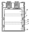
- the capacitor element is impregnated with an electrolytic solution, and the capacitor element impregnated with the electrolytic solution is inserted into a bottomed cylindrical outer case. Seal the exterior case with sealing rubber by crimping. That is, as shown in FIG. 3, the outer case is crimped to fix the capacitor element to the outer case.
- the pressing portion 8 is a protrusion which protrudes to the capacitor element side by caulking the outer case, and bites into the capacitor element to fix the capacitor element to the outer case.
- the pressing portion 8 forms the pressing portion 8 at a position toward the small area 32. In other words, the pressing portion 8 is formed avoiding the dividing portion 31.
- the electrode active material layer 3 does not exist at the position of the dividing portion 31. Therefore, the capacitor element is softened in the position of the dividing portion 31. Even if the pressing portion 8 is provided in the dividing portion 31, the fixation of the capacitor element becomes unstable.
- the electrode active material layer 3 does not serve as a reinforcing material in the dividing portion 31, when the pressing portion 8 is provided in the dividing portion 31, the stress of the pressing portion 8 is concentrated on the current collector 7. It becomes a factor of resistance increase, such as
- Example 1 The positive electrode foil and the negative electrode foil were stacked with the separator interposed therebetween, and these were wound to form a cylindrical capacitor element.
- the cylindrical capacitor element was impregnated with an electrolytic solution to produce an electric double layer capacitor of Example 1. The details are as follows.
- the etched aluminum foil is immersed in an aqueous solution of phosphoric acid to make phosphorus adhere to the surface, and a paint containing graphite is applied to the surface of the foil to form a carbon coat layer on the surface of the aluminum foil on both sides of the aluminum foil.
- the current collector 7 has a band shape.
- the current collector 7 of the positive electrode foil has a width of 144 mm in the cylinder axis direction orthogonal to the longitudinal direction of the band
- the current collector 7 of the negative electrode foil has a width 146 mm in the cylinder axial direction orthogonal to the longitudinal direction of the band Have.
- a slurry having a width of 40 mm in the axial direction was applied to the current collector 7 of the positive electrode foil along the longitudinal direction of the current collector 7.
- the slurry was applied in parallel in three rows at intervals of 7 mm in the axial direction of the cylinder. Then, the slurry was dried. That is, the electrode active material layer 3 formed on the current collector 7 of the positive electrode foil has an upper area U, a middle area M, and a lower area D each having a width of 40 mm by two 7 mm wide divided portions 31. It was divided into small areas 32.
- the electrode active material layer 3 formed on the current collector 7 of the negative electrode foil has an upper area U, a middle area M, and a lower area D each having a width of 42 mm by two divided portions 31 of 5 mm width. It was divided into small areas 32.
- the cylindrical capacitor element was impregnated with an electrolytic solution.
- the electrolyte used was a 1.5 M methyl ethyl pyrrolidinium BF 4 / propylene carbonate solution.
- the electrode terminal part was pulled out from one end surface of positive electrode foil and negative electrode foil. Then, the cylindrical capacitor element is placed in an outer case of ⁇ 40 ⁇ 170 L and sealed with a sealing body, and the pressing portion 8 is formed at a position facing the small area 32 to produce the electric double layer capacitor of Example 1 did.
- the electric double layer capacitor of Comparative Example 1 is different from the electric double layer capacitor of Example 1 in that the division portion 31 is not formed. That is, the slurry having a width of 144 mm was applied to the current collector 7 having a width of 144 mm and dried. That is, on the current collector 7 of the positive electrode foil, one line of the electrode active material layer 3 continuous across the width of 144 mm was applied. In addition, a slurry having a width of 146 mm was applied to the current collector 7 of the negative electrode foil having a width of 146 mm and dried. That is, on the current collector 7 of the negative electrode foil, one line of the electrode active material layer 3 continuous across the width of 146 mm was applied. In addition, the electric double layer capacitor of Comparative Example 1 was prepared with the same composition, the same manufacturing method and the same conditions as Example 1.
- the following method was adopted to measure the distribution of ion concentration. That is, the electric double layer capacitor was disassembled and the wound positive electrode foil was spread. The vicinity of the center of the positive electrode foil was cut along the cylinder axis, that is, cut in the width direction orthogonal to the longitudinal direction, and a rectangular measurement piece was cut out. The piece to be measured is cut out so that one side is the same as the cylinder axis direction of the positive electrode foil and the length of the side adjacent to this side is at least 5 cm or more, preferably 10 cm.
- the pieces to be measured are further divided into extraction regions (9 locations) described later, and each of the extraction regions is immersed in an acetonitrile solution at room temperature for 12 hours to extract the electrolyte solution, and the electrolyte solution extracted from each place is made 1000 times with pure water. Each diluted. Then, the ion concentration was quantified by chromatography using each diluted solution as a sample.
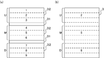
- the first to third extraction points belong to the small area 32 of the upper area U, and are arranged in order from the side where the electrode terminal portion is drawn out in ascending order of numbers.
- the fourth to sixth extraction points belong to the small area 32 of the middle abdominal area M, and are arranged in order from the side from which the electrode terminal portion is drawn out in ascending order of numbers.
- the seventh to ninth extraction points belong to the small area 32 of the lower area D, and are arranged in order from the side from which the electrode terminal portion is drawn out in ascending order of numbers.
- the electrolyte solution was extracted from a total of three places.
- Each extraction point corresponds to the second, fifth and eighth positions in the first embodiment.
- the second position is the center of the upper region U
- the fifth position is the center of the middle and middle region M
- the eighth position is the center of the lower region D.
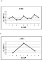
- FIG. 5 is a graph showing the ion concentration distribution of the electric double layer capacitors of Example 1 and Comparative Example 1.
- the 1st to 9th extraction places of Example 1 were arranged on the horizontal axis, and the ion concentration was taken on the vertical axis.
- the first to ninth extraction points of Comparative Example 1 are arranged on the horizontal axis, and the ion concentration is plotted at the second, fifth, and eighth extraction points among them.
- the ion concentration is about 1.4 M at the fifth extraction point, and about 0.2 M at the second extraction point. It became about 0.4 M in the extraction place of.
- the ion concentration in the middle abdominal area M was increased, and the ion concentration in the upper area U and the lower area D was decreased, and the difference was increased to about 1.2 M.
- the average of the ion concentration at the first to third extraction points is about 0.7 M
- the fourth to fifth The average ion concentration at the sixth extraction point was about 0.7 M
- the average ion concentration at the seventh to ninth extraction points was about 0.9 M. That is, by dividing the electrode active material layer 3 into a plurality of small regions 32 by the dividing portion 31, the difference between the ion concentration of the upper region U and the lower region D with respect to the middle abdominal region M is suppressed to about 0.2 M Was confirmed.
- the ion concentration of the first to third extraction points is 0.7 M, 0.9 M and 0.5 M, and the upper region is The ion concentration gradient was also gentle in the small area 32 of U.
- the ion concentration of the extraction points of No. 4 to No. 6 was 0.5 M, 1.0 M and 0.65 M, and the concentration gradient of the ions in the small area 32 of the middle abdominal area M was gentle.
- the ion concentration of the extraction points of No. 7 to No. 9 was 0.7 M, 1.2 M and 0.8 M, and the concentration gradient of the ions in the small area 32 of the lower area D was gentle. That is, it was confirmed that the difference in ion concentration is suppressed by narrowing the width of the small area 32 even in one small area 32.
- the ion concentration of the No. 2 extraction point is an extremely low value of 0.2 M
- any extraction point is The ion concentration at the point, that is, any one of the cation species or the anion species of the electrolytic solution shows a value exceeding 0.3 M, indicating that the influence on the characteristic deterioration can be reduced.
- the difference in concentration of ions in the capacitor 1 is alleviated. It was shown that 3 M or more could be maintained, and capacity degradation was suppressed.
- Example 2 In the electric double layer capacitor of Example 2, the width of the small region 32 of the electrode active material layer 3 in the positive electrode foil of the electric double layer capacitor of Example 1 is 30 mm, the width of the dividing portion 31 is 5 mm, and the electrode in the negative electrode foil is The width of the small area 32 of the active material layer 3 is 32 mm, and the width of the divided portion 31 is 3 mm.
- the width of the positive electrode foil was 100 mm, the width of the negative electrode foil was 102 mm, and the others were manufactured using the same material, the same method, and the same conditions as in Example 1.
- Example 3 In the electric double layer capacitor of Example 3, the width of the small region 32 of the electrode active material layer 3 in the positive electrode foil of the electric double layer capacitor of Example 1 is 40 mm, the width of the dividing portion 31 is 5 mm, and the electrode in the negative electrode foil is The width of the small region 32 of the active material layer 3 is 42 mm, and the width of the divided portion 31 is 3 mm.
- the width of the positive electrode foil was 130 mm, the width of the negative electrode foil was 132 mm, and the others were manufactured using the same material, the same method, and the same conditions as in Example 1.
- Example 4 In the electric double layer capacitor of Example 4, in the positive electrode foil of the electric double layer capacitor of Example 1, the width of the small region 32 of the electrode active material layer 3 is 50 mm, the width of the dividing portion 31 is 5 mm, and the electrode is negative electrode The width of the small region 32 of the active material layer 3 is 52 mm, and the width of the divided portion 31 is 3 mm.
- the width of the positive electrode foil was 160 mm, the width of the negative electrode foil was 162 mm, and the others were manufactured using the same material, the same method, and the same conditions as in Example 1.
- Example 5 In the electric double layer capacitor of Example 5, the width of the small area 32 of the electrode active material layer 3 in the positive electrode foil is 60 mm, the width of the dividing portion 31 is 5 mm, and the small area 32 of the electrode active material layer 3 in the negative electrode foil. The width was 62 mm, and the width of the dividing portion 31 was 3 mm. The width of the positive electrode foil was 190 mm, the width of the negative electrode foil was 192 mm, and the others were manufactured using the same material, the same method, and the same conditions as in Example 1.
- Example 6 In the electric double layer capacitor of Example 6, the width of the small region 32 of the electrode active material layer 3 in the positive electrode foil of the electric double layer capacitor of Example 1 is 70 mm, the width of the dividing portion 31 is 5 mm, and the electrode in the negative electrode foil is The width of the small region 32 of the active material layer 3 is 72 mm, and the width of the division 31 is 3 mm.
- the width of the positive electrode foil was 220 mm, the width of the negative electrode foil was 222 mm, and the others were manufactured using the same material, the same method, and the same conditions as in Example 1.
- Example 2 when the charge and discharge are repeated 40,000 times, the capacity deterioration was found to be 10.1% in Example 2 where the width of the small area 32 is 30 mm, and Example 3 in which the width of the small area 32 is 40 mm.
- Example 4 of 8.7%, small area 32 having a width of 50 mm is 13.7%,
- Example 5 of small area 32 having a width of 60 mm is 17.2%, and
- Example 6 of small area 32 having a width of 70 mm Was 19.1%.
- the width of the small area 32 is narrowed, capacity deterioration is alleviated. It was also confirmed that when the width of the small area 32 is 50 mm or less, the decrease in capacity is moderate around 10,000 cycles, which greatly contributes to the effect of suppressing the capacity deterioration when 40,000 cycles are achieved. Therefore, the width of the small area 32 is desirably 50 mm or less.
- Examples 7 to 10 The electric double layer capacitors of Examples 7 to 10 are shown in Table 3 for the width of the small region 32 of the electrode active material layer 3 and the width of the divided portion 31 in the positive electrode foil and the negative electrode foil of the electric double layer capacitor of Example 1. The dimensions were set to the dimensions shown, and the others were fabricated using the same materials, the same method, and the same conditions as in Example 1.
- the small region 32 on the negative electrode foil side is narrower than the small region 32 on the positive electrode foil side, and the small region 32 on the positive electrode foil side does not face the small region 32 on the negative electrode side.
- This embodiment differs from the first embodiment in that a non-facing region is present.
- a 40 mm wide slurry was applied at intervals of 1 mm along the longitudinal direction of the current collector 7 to the current collector 7 of the positive electrode foil and dried.
- three small regions 32 each having a width of 40 mm were formed, and a positive electrode foil in which three small regions 32 were divided by two division portions 31 each having a width of 1 mm was formed.
- the current collector 7 of this negative electrode foil With respect to the current collector 7 of this negative electrode foil, a 38 mm wide slurry was applied at intervals of 3 mm along the longitudinal direction of the current collector 7 and dried. As a result, three small regions 32 each having a width of 38 mm were formed, and a negative electrode foil in which the three small regions 32 were divided by two divided portions 31 each having a width of 3 mm was formed. Therefore, the 2 mm width of the small regions 32 of the positive electrode foil is a non-facing region not facing the small region 32 of the negative electrode foil, and a total of 6 mm non-facing regions are formed in the three small regions 32.
- Example 7 in which the width of the divided portion 31 on the positive electrode side is 1 mm is Example 8 of 14.5%, 3 mm width of divided part 31 is 10.3%, Example 9 of 5 mm width of divided part 31 is 8.8%, Example 10 of 11 mm width of divided part 31 was 8.3%.
- the width of the dividing portion 31 is preferably 3 mm or more in consideration of manufacturing variations.
- the electric double layer capacitor of Example 7 has a large degree of capacity deterioration as compared to Example 8, which is caused by the presence of the non-facing region in the small region 32 of the positive electrode foil. Conceivable.
- the small area 32 of the positive electrode foil does not have a portion that does not directly face the electrode active material layer 3 of the negative electrode foil, that is, the small area of the negative electrode foil covers the small area of the positive electrode foil facing through the separator. was confirmed to be desirable.
- Example 11 An electric double layer capacitor is prepared in which the divided portions of the positive electrode foil and the negative electrode foil have a width of 6 mm, and the widths of small regions of the polarizable electrodes on the positive electrode side and the negative electrode side are changed from 20 mm to 60 mm in 10 mm steps. The volume after 10,000 times was measured.
- This electric double layer capacitor was a ⁇ 63.5 ⁇ 172 L wound type electric double layer capacitor, and used had a rated voltage of 2.5 V and a rated capacity of 3600 F. The results are shown in Table 4.
- the capacity is 2880 F due to capacity deterioration after 40,000 cycle tests.
- the width of the small area 32 was 30 mm or more, the capacity exceeded 2880 F of Comparative Example 1. Therefore, it was confirmed that the width of the small area 32 is desirably 30 mm or more.
- Example 12 The electric double layer capacitor of Example 12 is the same as Example 1 in that the same division 31 as in Example 1 is provided in the electrode active material layer 3 of the positive electrode foil and the electrode active material layer 3 is divided into small regions 32.
- the division is not provided in the electrode active material layer 3 of the negative electrode foil, that is, it differs from Example 1 in that the negative electrode foil of Comparative Example 1 is used, and the other materials are the same as those of Example 1 in the same manner. And produced under the same conditions.
- Example 13 A hybrid capacitor according to Example 13 in which the divisions 31 were formed on the positive electrode foil and the negative electrode foil was produced.
- the hybrid capacitor of this Example 13 uses the same positive electrode foil as in Example 1, and the number and width of the small regions 32 of the positive electrode foil and the negative electrode foil, and the number and width of the divisions 31 are the same as in Example 1. It is. However, in the hybrid capacitor of this Example 13, a Faraday reaction electrode in which lithium titanate is used as the electrode active material layer 3 was used as the negative electrode foil.
- As an electrolytic solution a propylene carbonate solution containing 1.5 M of LiBF 4 as a solute was used.
- the slurry containing lithium titanate was applied to the current collector 7 having a width of 146 mm in the cylinder axis direction along the longitudinal direction of the current collector 7 with a 42 mm width slurry in the cylinder axis direction.
- the slurry was applied in parallel in three rows at intervals of 5 mm in the axial direction of the cylinder. That is, the electrode active material layer 3 formed on the current collector 7 of the negative electrode foil has an upper area U, a middle area M, and a lower area D each having a width of 42 mm by two divided portions 31 of 5 mm width. It was divided into small areas 32.
- the positive electrode foil was applied in parallel to the current collector 7 having a width of 144 mm in the cylinder axis direction at intervals of 7 mm in the cylinder axis direction. That is, the electrode active material layer 3 formed on the current collector 7 of the positive electrode foil has an upper area U, a middle area M, and a lower area D each having a width of 40 mm by two 7 mm wide divided portions 31. It was divided into small areas 32.
- Comparative example 2 The hybrid capacitor of Comparative Example 2 differs from the hybrid capacitor of Example 13 in that the dividing portion 31 is not formed.
- the hybrid capacitor of Comparative Example 2 was manufactured using the same material, the same method, and the same conditions as in Example 13 except for the above.
Landscapes
- Engineering & Computer Science (AREA)
- Power Engineering (AREA)
- Microelectronics & Electronic Packaging (AREA)
- Chemical & Material Sciences (AREA)
- Materials Engineering (AREA)
- Chemical Kinetics & Catalysis (AREA)
- Electrochemistry (AREA)
- Electric Double-Layer Capacitors Or The Like (AREA)
Abstract
分極性電極を有するキャパシタにおいて、充放電サイクルを繰り返すと生じる容量劣化を抑制する。電極箔は、集電体7と電極活物質層3とにより成る。電極活物質層3は集電体7の表面に形成される。この電極活物質層3は、分割部32で分割され、複数の小領域31に分けられる。この電極箔は、正極箔又は正極箔と負極箔に用いることができ、電気二重層キャパシタ又はハイブリッドキャパシタの容量劣化を抑制できる。
Description
本発明は、分極性電極などの電極活物質層を備えるキャパシタ用電極箔及びキャパシタに関する。
電気二重層キャパシタは、一対の分極性電極の間に電解質を充填して構成される。ハイブリッドキャパシタは、正極側に分極性電極を備え、負極側にリチウムイオンを吸蔵放出可能な金属化合物粒子や炭素材料の層を備える。電気二重層キャパシタもハイブリッドキャパシタも、分極性電極と電解質との境界面に形成される電気二重層の蓄電作用を利用している。尚、ハイブリッドキャパシタの負極はファラデー反応電極である。
これら分極性電極を有するキャパシタを充電すると、分極性電極と電解質との界面に荷電粒子が整列する。正極において、電解質のアニオンは、分極性電極との界面に整列し、分極性電極内の空孔と極めて短い距離を隔てて対を成す。これにより、正極には電位障壁が形成される。電気二重層キャパシタの場合は、負極においても電解質のカチオンが分極性電極との界面に整列し、分極性電極内の電子と極めて短い距離を隔てて対を成し、負極に電位障壁が形成される。
このように、電気二重層を利用するキャパシタは、充放電に化学反応を利用せず物理的に電荷を蓄える。そのため、電気二重層を利用するキャパシタは構成材料の劣化が少なく、充放電サイクル寿命に優れる。従って、電気二重層を利用するキャパシタは、定期的な部品交換が困難な用途や設置場所において、交換頻度の低減やメンテナンスフリーを目的に採用されることも多い。
本発明者らの鋭意研究によれば、電気二重層キャパシタのフロート試験として、摂氏30度の温度環境下で2.5Vの直流電圧を1400時間程度印加し続けても、大きな容量劣化は見られなかったが、電気二重層キャパシタの充放電を繰り返すと容量が徐々に低下し、4万回の充放電サイクルが経過すると、初期と比べて容量が20%低下する現象が見られた。
そこで、本発明は、上記課題を解決すべく、充放電サイクルによる容量の劣化が抑制されたキャパシタ用電極箔及びキャパシタを提供することを目的とする。
本発明者等は、巻回形の電気二重層キャパシタを2個作製し、第1の電気二重層キャパシタに対して4万回の充放電サイクル試験を行い、第2の電気二重層キャパシタに対して5000時間のフロート試験を行った。そして、第1及び第2の電気二重層キャパシタの正極側の分極性電極、負極側の分極性電極、及びセパレータに対して、各々3箇所のイオン濃度(M)を定量した。イオン濃度は、電解液のカチオン種、またはアニオン種のうち、いずれかの濃度であり、定量する場所が正極であるか、負極であるか、セパレータであるかによって異なる。
ここで、巻回形の電気二重層キャパシタは円筒型コンデンサ素子を有する。円筒型コンデンサ素子は、正極箔と負極箔とをセパレータを挟んで重ね合わせ、巻軸を中心に渦巻き状に巻き込むと、この円筒型コンデンサ素子が作成される。円筒型コンデンサ素子の一端面から電極端子部が引出される。イオン濃度(M)の定量箇所は、筒軸に沿って円筒型コンデンサ素子を3等分したとき、電極端子部が引出された端面に繋がる筒軸上部付近(以下、上部域という)、筒軸中腹付近(以下、中腹域という)、及び電極端子部が引出された端面とは反対の端面に繋がる筒軸下部付近(以下、下部域という)である。その結果を下記表1に示す。各数値の単位はM(mol/L)である。
(表1)
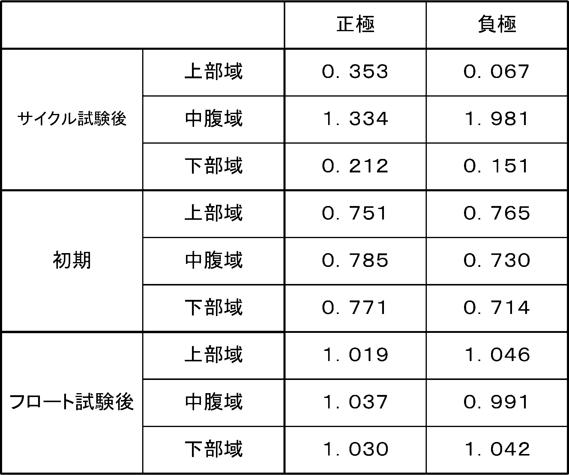
表1に示すように、充放電サイクル試験及びフロート試験前の初期では、上部域も下部域も中腹域もイオンの濃度は同等である。しかし、4万回の充放電サイクル試験後、上部域と下部域のイオン濃度が初期と比べて薄くなり、中腹域のイオン濃度が初期と比べて濃くなっていた。即ち、充放電が繰り返されると、イオンが上部域と下部域から中腹域に移動し、電気二重層キャパシタ内部でイオンの濃度勾配が生じていることがわかった。尚、フロート試験後においては、イオンの濃度勾配は生じていなかった。
本発明者らは、充放電を繰り返されるとイオンの濃度勾配が発生し、分極性電極と電解質との界面にはイオンの疎な領域が存在すると考えた。イオンが疎の領域で発現する容量は小さく、その結果、キャパシタ全体としても容量低下が生じていると考えた。
そこで、本発明に係るキャパシタ用電極箔は、集電体と、前記集電体の表面に形成された電極活物質層と、前記電極活物質層を小領域に分割する分割部と、を備えること、を特徴とする。電極活物質層を小領域に分割すれば、小領域間でのイオンの移動が抑制され、イオンの濃度勾配の発生が抑制される。
前記電極活物質層は帯形状を有し、前記分割部は、前記電極活物質層の帯長手方向に延びて、前記電極活物質層を帯長手方向に沿って延びる帯状の小領域に分割する溝であり、前記小領域は、前記分割部と直交する方向に沿った帯幅方向の長さが30mm以上50mm以下であるようにしてもよい。同じ小領域内で生じ得るイオンの濃度勾配を緩やかにでき、容量が小さくなる領域をより極小化できる。
前記電極活物質層は帯形状を有し、前記分割部は、前記電極活物質層の帯長手方向に延びて、前記電極活物質層を帯長手方向に沿って延びる帯状の小領域に分割する溝であり、幅が1mm以上であるようにしてもよい。小領域間のイオンの移動が効果的に抑制されるとともに、電極活物質層の表面積の低下が最小限に抑えられる。
前記電極活物質層は帯形状を有し、前記分割部は、前記電極活物質層の帯長手方向に沿って延在するようにしてもよい。上部域から中腹域へ、また下部域から中腹域へのイオンの移動を抑制できる。
このようなキャパシタ用電極箔と電解液を備えるキャパシタも本発明の一態様である。例えば、正極及び負極の両方に分極性電極を有する電気二重層キャパシタ、正極側に分極性電極を備え、負極側に、リチウムイオンを吸蔵及び放出する金属化合物粒子の層により成る電極を備えるハイブリッドキャパシタも本発明の一態様である。
このキャパシタにおいては、正極側にのみ前記キャパシタ用電極箔を備えるようにすればよい。正極側の電極箔が有する電極活物質層を分割部で小領域に分割すると、分割部を有していない負極側の電極活物質層でもイオン濃度の差が抑制された。もちろん、少なくとも正極側に前記キャパシタ用電極箔を備えるようにすればよく、正極及び負極の両方に前記キャパシタ用電極箔を備えてもよい。
また、正極側に前記分割部を有する前記キャパシタ用電極箔を備え、前記正極側の前記小領域は、対向する負極の活物質層で覆われているようにしてもよい。また、正極と負極の両方に前記分割部を有する前記キャパシタ用電極箔を備え、前記正極の前記小領域の幅は、前記負極の前記小領域の幅よりも狭く、前記正極の前記小領域は、対向する前記負極の前記小領域で覆われているようにしてもよい。正極側に負極側の電極活物質と正対していない非対向領域を無くすことができ、容量劣化が更に抑制される。
また、前記キャパシタ用電極箔をセパレータを介して巻回され、電解液が含有されたキャパシタ素子と、前記キャパシタ素子を収納する外装ケースと、前記外装ケースの側面を押圧して前記キャパシタ素子を固定する押圧部と、を備え、前記押圧部は、前記分割部の位置と一致せず、前記小領域の位置に形成されるようにしてもよい。押圧部によってキャパシタ素子が良好に捕捉され、外装ケース内でキャパシタ素子が不安定になることがないため、分割部が耐振性に影響を与えることがない。
本発明によれば、キャパシタを繰り返し充放電しても、容量の劣化が抑制される。
以下、本発明に係る電極箔及びこの電極箔を備えたキャパシタの実施形態について図面を参照しつつ詳細に説明する。なお、本発明は、以下に説明する実施形態に限定されるものでない。
(全体構造)
キャパシタは、正極箔及び負極箔に電極活物質の層を備え、正極箔または負極箔の少なくとも一方の分極性電極と電解液との境界面に形成される電気二重層の蓄電作用を利用する。典型的には、このキャパシタは電気二重層キャパシタ又はハイブリッドキャパシタである。電気二重層キャパシタは、正極箔及び負極箔の両方に分極性電極を有する。ハイブリッドキャパシタは、正極箔に分極性電極を有し、負極箔にリチウムイオンを吸蔵放出可能な金属化合物粒子により成る電極活物質の層または炭素材料のファラデー反応電極を有する。キャパシタの形状としては、巻回形又は積層形を採ることができる。以下、巻回形のキャパシタを例示する。
キャパシタは、正極箔及び負極箔に電極活物質の層を備え、正極箔または負極箔の少なくとも一方の分極性電極と電解液との境界面に形成される電気二重層の蓄電作用を利用する。典型的には、このキャパシタは電気二重層キャパシタ又はハイブリッドキャパシタである。電気二重層キャパシタは、正極箔及び負極箔の両方に分極性電極を有する。ハイブリッドキャパシタは、正極箔に分極性電極を有し、負極箔にリチウムイオンを吸蔵放出可能な金属化合物粒子により成る電極活物質の層または炭素材料のファラデー反応電極を有する。キャパシタの形状としては、巻回形又は積層形を採ることができる。以下、巻回形のキャパシタを例示する。
これらキャパシタは、正極箔、負極箔、セパレータ及び電解液を備える。正極箔、負極箔及びセパレータは帯形状を有する。正極箔と負極箔はセパレータを挟んで重ね合わせられ、帯の長尺方向が周を形成するように渦巻き状に巻回されて、円筒型コンデンサ素子に成型されている。このコンデンサ素子には電解液が含浸されている。尚、電解液は、電解質を保持できれば媒体は液体でなくてよく、固体高分子でもゲル電解質でもよい。
(電極箔)
図1は電極箔1を示す模式図であり、(a)は断面斜視図、(b)は平面図である。図1に示すように、正極箔及び負極箔となる電極箔1は、集電体7に分極性電極又はファラデー電極等の電極活物質層3を形成させて成る。集電体7は、アルミニウム、白金、金、ニッケル、チタン及び鋼等の弁作用を有する金属である。集電体7の形状は、膜状、箔状、板状などの任意の形状を採用することができる。また集電体7の表面はエッチング処理などによる凹凸面を形成してもよく、またプレーン面であってもよい。さらには、表面処理を行い、リンを集電体7の表面に付着させてもよい。
図1は電極箔1を示す模式図であり、(a)は断面斜視図、(b)は平面図である。図1に示すように、正極箔及び負極箔となる電極箔1は、集電体7に分極性電極又はファラデー電極等の電極活物質層3を形成させて成る。集電体7は、アルミニウム、白金、金、ニッケル、チタン及び鋼等の弁作用を有する金属である。集電体7の形状は、膜状、箔状、板状などの任意の形状を採用することができる。また集電体7の表面はエッチング処理などによる凹凸面を形成してもよく、またプレーン面であってもよい。さらには、表面処理を行い、リンを集電体7の表面に付着させてもよい。
電極箔1は、例えば、電気二重層容量を持つ多孔質構造又は繊維状構造を有する炭素材料や、ファラデー反応を生じる金属化合物粒子や炭素材料などの電極活物質層3の材料である電極材料と、導電助剤との混合物にバインダーを混合し、混練した後シート状に成形して形成することができる。また、電極材料と導電助剤とバインダーの混合液をドクターブレード法等によって集電体7上に塗工し、乾燥することにより電極を形成しても良い。電極箔1は、得られた分散物を所定形状に成形し、集電体7上に圧着して形成することもできる。この電極箔1の厚みは20~150μmが望ましい。
バインダーとしては、例えばフッ素系ゴム、ジエン系ゴム、スチレン系ゴム等のゴム類、ポリテトラフルオロエチレン、ポリフッ化ビニリデン等の含フッ素ポリマー、カルボキシメチルセルロース、ニトロセルロース等のセルロース、その他、ポリオレフィン樹脂、ポリイミド樹脂、アクリル樹脂、ニトリル樹脂、ポリエステル樹脂、フェノール樹脂、ポリ酢酸ビニル樹脂、ポリビニルアルコール樹脂、エポキシ樹脂などを挙げることができる。これらのバインダーは、単独で使用しても良く、2種以上を混合して使用しても良い。
導電助剤としては、ケッチェンブラック、アセチレンブラック、天然/人造黒鉛、繊維状炭素等を用いることができ、繊維状炭素としては、カーボンナノチューブ、カーボンナノファイバ(以下、CNF)などの繊維状炭素を挙げることができる。カーボンナノチューブは、グラフェンシートが1層である単層カーボンナノチューブ(SWCNT)でも、2層以上のグラフェンシートが同軸状に丸まり、チューブ壁が多層をなす多層カーボンナノチューブ(MWCNT)でもよく、それらが混合されていてもよい。
分極性電極における電極活物質層3の材料は代表的には炭素粉末である。炭素粉末に導電助剤を添加してもよい。炭素粉末は、水蒸気賦活、アルカリ賦活、塩化亜鉛賦活又は電界賦活等の賦活処理並びに開口処理が施されてもよい。炭素粉末としては、やしがら等の天然植物組織、フェノール等の合成樹脂、石炭、コークス、ピッチ等の化石燃料由来のものを原料とする活性炭、ケッチェンブラック、アセチレンブラック、チャネルブラックなどのカーボンブラック、カーボンナノホーン、無定形炭素、天然黒鉛、人造黒鉛、黒鉛化ケッチェンブラック、活性炭、メソポーラス炭素などを挙げられる。
ファラデー電極における電極活物質層3としては、金属化合物粒子や炭素材料を用いた層を形成させて成る。金属化合物粒子層は、リチウムイオンを吸蔵及び放出することが可能であり、例えばFeO、Fe2O3、Fe3O4、MnO、MnO2、Mn2O3、Mn3O4、CoO、Co3O4、NiO、Ni2O3、TiO、TiO2、TiO2(B)、CuO、NiO、SnO、SnO2、SiO2、RuO2、WO、WO2、WO3、MoO3、ZnO等の酸化物、Sn、Si、Al、Zn等の金属、LiVO2、Li3VO4、Li4Ti5O12、Sc2TiO5、Fe2TiO5、LiFePO4、Li3V2(PO4)3などの複合酸化物、Li2.6Co0.4N、Ge3N4、Zn3N2、Cu3Nなどの窒化物、Y2Ti2O5S2、MoS2が挙げられる。また、炭素材料としては、黒鉛(グラファイト)、難黒鉛化炭素(ハードカーボン)およびコークスなどが挙げられる。
ハイブリッドキャパシタの負極箔にファラデー反応電極を用いる場合は、正極箔の集電体7及び電極活物質層3を貫く貫通孔を備えず、また負極箔の集電体7及び炭素材料層を貫く貫通孔を備えないものが望ましい。
集電体7と電極活物質層3の間には、黒鉛等の導電剤を含むカーボンコート層を設けても良い。集電体の表面に黒鉛等の導電剤、バインダー等を含むスラリーを塗布、乾燥することで、カーボンコート層を形成することができる。
電極活物質層3内には、電極箔1の一辺に沿って一直線に延在する分割部31を備える。分割部31は、電極活物質層3の層表面から層底まで、電極活物質層3の材料が存在せず、集電体7又はカーボンコート層が露出している細線領域であり、電極活物質層3を端から端まで完全に切り開く。電極活物質層3は、分割部31で帯状の複数の小領域32に分割される。小領域32間は分割部31によって繋がりを喪失する。
この分割部31は、平行に単数条又は複数条が延設される溝又は凹部である。電極活物質層3は、分割部31の本数に応じて二条以上の小領域32に分割される。例えば分割部31は、正極箔の帯長手方向に沿って二条形成され、小領域32は、帯長手方向と直交する方向に並び、筒軸方向に上部域Uと中腹域Mと下部域Dに分かれて、互いに平行に延在する。この分割部31は、分割部31となる領域に予め電極活物質層3のスラリーを塗工しない、または電極活物質層3のシートを接合しないことで形成してもよく、その他、集電体7上に形成された電極活物質層3の一部をレーザーやブラシ、その他の機械的手法によって除去して分割部を形成してもよい。
分割部31を有する電極活物質層3によると、分割部31によって電極活物質層3内のイオンが小領域32間を移動し難くなる。そのため、電極活物質層3内では、分割部31と直交する方向に拡がるイオンの濃度勾配が抑制される。そうすると、電極活物質層3内においてイオン濃度が薄い領域が生じ難くなり、キャパシタ1の容量劣化が抑制される。また、一条の小領域32の幅は、電極活物質層3の全幅と比べて狭くなるため、一条の小領域32内でもイオンの濃淡差が付き難くなる。従って、一条の小領域32内でもイオン濃度の薄い領域が生じ難くなり、キャパシタ1の容量劣化が抑制される。
電極活物質層3の全体面積Xに占める小領域32の合計面積Yは、Y=(0.8/0.9)X以上が望ましい。第1に、分割部31を設けると容量維持率は9割程度(後述の実施例1では8%低下し、容量維持率は92%)になること、第2に、分割部31はキャパシタ1の容量に寄与しないこと、第3に、分割部31が無いとキャパシタ1の容量維持率は8割程度まで落ち込むことより、小領域32の合計面積Yであると、分割部31を設けずに容量劣化が発生したキャパシタの容量を上回る。
分割部31の長さは、電極活物質層3の端から端までであり、分割部31の幅は望ましくは1mm以上である。換言すると、隣接する小領域32は1mm以上の間隔で離間する。1mm以上であれば、電極活物質層3内のイオンの移動が効果的に抑制できる。但し、製造の都合上、3mm以上が望ましい。また、容量劣化の抑制効果は分割部31の幅が大きければ良いが、6mmを超えると小領域32の合計面積YがY=(0.8/0.9)Xを満たし難くなる。
小領域32の幅は望ましくは20mm以上50mm以下である。小領域32の幅とは、電極活物質層3の端に属する小領域32においては、電極活物質層3の端から分割部31まで、電極活物質層3の内側に属する小領域32においては、分割部31間である。小領域32の幅が50mmを超えても、分割部31による容量劣化の抑制効果は発揮されるが、その効果は徐々に薄れていく。また、20mmを下回ると、小領域32の合計面積YがY=(0.8/0.9)Xを満たし難くなる。
キャパシタにおいては、少なくとも正極箔の電極活物質層3が分割部31で小領域32に分断されていればよい。もちろん、負極箔の電極活物質層3も小領域32と分割部31を備えるようにしてもよい。但し、電気的中性を保つことが原因と推測されるが、正極箔又は負極箔の一方の電極活物質層3を分割部31と小領域32とで構成すれば、他方の電極活物質層3に分割部31を形成しなくとも、当該他方の電極活物質層3内においてイオンの濃淡差が抑制されるとの知見を得た。
図2は、正極箔と負極箔の位置関係を示す模式図である。図2に示すように、正極箔と負極箔の両方の電極3に分割部31を形成する場合には、負極箔の小領域32を正極箔の小領域32より幅広にし、正極箔の小領域32が負極箔の小領域32によって覆われ、はみ出ないようする。即ち、正極箔の電極3に、負極箔の電極3と正対していない領域が発生しないようにすることが望ましい。負極箔の電極3と正対していない非対向領域の酸化劣化を抑制するためである。
(電解液)
電解液は、溶媒に対して溶質を溶解し、または更に添加剤が添加された混合液である。この電解液の溶質のイオン濃度は1.0~3.0(M)に設定することで、充放電サイクル試験後のイオン濃度が所定量維持できる。溶媒としては、エチレンカーボネート、プロピレンカーボネート、ビニレンカーボネート、ブチレンカーボネート、4-フルオロ-1,3-ジオキソラン-2-オン、4-(トリフルオロメチル)-1,3-ジオキソラン-2-オンなどの環状カーボネート、ジメチルカーボネート、エチルメチルカーボネート、ジエチルカーボネート、メチルn-プロピルカーボネート、メチルイソプロピルカーボネート、n-ブチルメチルカーボネート、ジエチルカーボネート、エチルn-プロピルカーボネート、エチルイソプロピルカーボネート、n-ブチルエチルカーボネート、ジn-プロピルカーボネート、ジイソプロピルカーボネート、ジn-ブチルカーボネート、フルオロエチルメチルカーボネート、ジフルオロエチルメチルカーボネート、トリフルオロエチルメチルカーボネートなどの鎖状カーボネート、エチルイソプロピルスルホン、エチルメチルスルホン、エチルイソブチルスルホンなどの鎖状スルホン、スルホラン、3-メチルスルホラン、γ-ブチロラクトン、アセトニトリル、1,2-ジメトキシエタン、N-メチルピロリドン、ジメチルホルムアミド、ジメチルスルホキシド、テトラヒドロフラン、2-メチルテトラヒドロフラン、1,3-ジオキソラン、ニトロメタン、エチレングリコール、エチレングリコールジメチルエーテル、エチレングリコールジエチルエーテル、水又はこれらの混合物を使用することができる。
電解液は、溶媒に対して溶質を溶解し、または更に添加剤が添加された混合液である。この電解液の溶質のイオン濃度は1.0~3.0(M)に設定することで、充放電サイクル試験後のイオン濃度が所定量維持できる。溶媒としては、エチレンカーボネート、プロピレンカーボネート、ビニレンカーボネート、ブチレンカーボネート、4-フルオロ-1,3-ジオキソラン-2-オン、4-(トリフルオロメチル)-1,3-ジオキソラン-2-オンなどの環状カーボネート、ジメチルカーボネート、エチルメチルカーボネート、ジエチルカーボネート、メチルn-プロピルカーボネート、メチルイソプロピルカーボネート、n-ブチルメチルカーボネート、ジエチルカーボネート、エチルn-プロピルカーボネート、エチルイソプロピルカーボネート、n-ブチルエチルカーボネート、ジn-プロピルカーボネート、ジイソプロピルカーボネート、ジn-ブチルカーボネート、フルオロエチルメチルカーボネート、ジフルオロエチルメチルカーボネート、トリフルオロエチルメチルカーボネートなどの鎖状カーボネート、エチルイソプロピルスルホン、エチルメチルスルホン、エチルイソブチルスルホンなどの鎖状スルホン、スルホラン、3-メチルスルホラン、γ-ブチロラクトン、アセトニトリル、1,2-ジメトキシエタン、N-メチルピロリドン、ジメチルホルムアミド、ジメチルスルホキシド、テトラヒドロフラン、2-メチルテトラヒドロフラン、1,3-ジオキソラン、ニトロメタン、エチレングリコール、エチレングリコールジメチルエーテル、エチレングリコールジエチルエーテル、水又はこれらの混合物を使用することができる。
溶質としては、電気二重層キャパシタにおいては、第4級アンモニウム塩が挙げられる。ハイブリッドキャパシタとしては、溶質は1種以上のリチウム塩が挙げられ、第4級アンモニウム塩を添加してもよい。
第4級アンモニウム塩としては、カチオンとしてテトラエチルアンモニウム、トリエチルメチルアンモニウム、ジエチルジメチルアンモニウム、エチルトリメチルアンモニウム、メチルエチルピロリジニウム、スピロビピロリジニウム、スピロ-(N,N’)-ビピロリジニウム、1-エチル-3-メチルイミダゾリウム、1-エチル-2,3-ジメチルイミダゾリウム等を挙げることができ、アニオンとしては、BF4
-、PF6
-、ClO4
-、AsF6
-、SbF6
-、AlCl4
-、またはRfSO3
-、(RfSO2)2N-、RfCO2
-(Rfは炭素数1~8のフルオロアルキル基)等を挙げることができる。特に、エチルトリメチルアンモニウムBF4、ジエチルジメチルアンモニウムBF4、トリエチルメチルアンモニウムBF4、テトラエチルアンモニウムBF4、スピロ-(N,N’)-ビピロリジニウムBF4、メチルエチルピロリジニウムBF4、エチルトリメチルアンモニウムPF6、ジエチルジメチルアンモニウムPF6、トリエチルメチルアンモニウムPF6、テトラエチルアンモニウムPF6、スピロ-(N,N’)-ビピロリジニウムPF6、テトラメチルアンモニウムビス(オキサラト)ボレート、エチルトリメチルアンモニウムビス(オキサラト)ボレート、ジエチルジメチルアンモニウムビス(オキサラト)ボレート、トリエチルメチルアンモニウムビス(オキサラト)ボレート、テトラエチルアンモニウムビス(オキサラト)ボレート、スピロ-(N,N’)-ビピロリジニウムビス(オキサラト)ボレート、テトラメチルアンモニウムジフルオロオキサラトボレート、エチルトリメチルアンモニウムジフルオロオキサラトボレート、ジエチルジメチルアンモニウムジフルオロオキサラトボレート、トリエチルメチルアンモニウムジフルオロオキサラトボレート、テトラエチルアンモニウムジフルオロオキサラトボレート、スピロ-(N,N’)-ビピロリジニウムジフルオロオキサラトボレート等が好ましい。
リチウム塩としては、LiPF6、LiBF4、LiClO4、LiN(SO2CF3)2、LiN(SO2C2F5)2、CF3SO3Li、LiC(SO2CF3)3、およびLiPF3(C2F5)3、またはこれらの混合物である。
また、添加剤としては、リン酸類及びその誘導体(リン酸、亜リン酸、リン酸エステル類、ホスホン酸類等)、ホウ酸類及びその誘導体(ホウ酸、酸化ホウ酸、ホウ酸エステル類、ホウ素と水酸基及び/又はカルボキシル基を有する化合物との錯体等)、硝酸塩(硝酸リチウム等)、ニトロ化合物(ニトロ安息香酸、ニトロフェノール、ニトロフェネトール、ニトロアセトフェノン、芳香族ニトロ化合物等)等があげられる。添加剤量は、導電性の観点から好ましくは電解質全体の10重量%以下であり、さらに好ましくは5重量%以下である。また、ガス吸収剤を含有してもよい。電極から発生するガスの吸収剤として、電解質の各成分(溶媒、電解質塩、各種添加剤等)と反応せず、かつ、除去(吸着など)しないものであれば、特に制限されない。具体例としては、例えば、ゼオライト、シリカゲルなどが挙げられる。
(セパレータ)
セパレータとしては、セルロース系セパレータ、合成繊維不織布系セパレータ、セルロースと合成繊維を混抄した混抄紙あるいは多孔質フィルムなどが使用できる。セルロースとしては、クラフト、マニラ麻、エスパルト、ヘンプ、レーヨンなどがある。不織布としては、ポリエステル、ポリフェニレンサルファイド、ポリエチレンテレフタレート、ポリブチレンテレフタレート、ポリアミド、ポリイミド、フッ素樹脂、ポリプロピレンやポリエチレン等のポリオレフィン系樹脂、セラミクスやガラス等々の繊維がある。
セパレータとしては、セルロース系セパレータ、合成繊維不織布系セパレータ、セルロースと合成繊維を混抄した混抄紙あるいは多孔質フィルムなどが使用できる。セルロースとしては、クラフト、マニラ麻、エスパルト、ヘンプ、レーヨンなどがある。不織布としては、ポリエステル、ポリフェニレンサルファイド、ポリエチレンテレフタレート、ポリブチレンテレフタレート、ポリアミド、ポリイミド、フッ素樹脂、ポリプロピレンやポリエチレン等のポリオレフィン系樹脂、セラミクスやガラス等々の繊維がある。
(組み立て方法)
このようなキャパシタの組み立て方法は次のとおりである。まず、陽極箔、陰極箔及びセパレータを帯長手方向及び帯幅方向を揃えて重ね合わせる。セパレータは陽極箔及び陰極箔の間に挟み込む。この陽極箔、陰極箔及びセパレータを、巻軸を中心に渦巻き状に巻き込むことで、円筒体状のコンデンサ素子を形成する。円筒体の一端面には、陽極箔及び陰極箔に繋がる電極端子部が引き出しておく。
このようなキャパシタの組み立て方法は次のとおりである。まず、陽極箔、陰極箔及びセパレータを帯長手方向及び帯幅方向を揃えて重ね合わせる。セパレータは陽極箔及び陰極箔の間に挟み込む。この陽極箔、陰極箔及びセパレータを、巻軸を中心に渦巻き状に巻き込むことで、円筒体状のコンデンサ素子を形成する。円筒体の一端面には、陽極箔及び陰極箔に繋がる電極端子部が引き出しておく。
このコンデンサ素子に電解液を含浸させ、電解液を含浸させたコンデンサ素子を有底筒状の外装ケースに挿入する。外装ケースを加締めにより封口ゴムで封止する。即ち、図3に示すように、外装ケースを加締めて、コンデンサ素子を外装ケースに固定する。この押圧部8は、外装ケースの加締めにより、コンデンサ素子側へ突き出した突起であり、コンデンサ素子に食い込んで、コンデンサ素子を外装ケースに固定する。
押圧部8は、小領域32に向かう位置に押圧部8を形成しておく。換言すると、押圧部8は、分割部31を避けて形成される。分割部31の位置には電極活物質層3が存在しない。そのため、分割部31の位置は、コンデンサ素子が柔らかくなっており、分割部31に押圧部8を設けても、コンデンサ素子の固定が不安定になってしまう。また、分割部31は電極活物質層3が補強材とならないために、分割部31に押圧部8を設けてしまうと、押圧部8の応力が集電体7に集中し、集電体7が過度に延びるなど、抵抗増加の要因となる。
一方、押圧部8を小領域32に向かうように設ければ、コンデンサ素子が外装ケース内で安定し、耐振性が良好となる。
以下、実施例に基づいて本発明をさらに詳細に説明する。なお、本発明は下記実施例に限定されるものではない。
(実施例1)
正極箔と負極箔をセパレータを挟んで重ね合わせ、これらを巻回することで、円筒型コンデンサ素子を作成した。この円筒型コンデンサ素子に電解液を含浸し、実施例1の電気二重層キャパシタを作製した。詳細は次のとおりである。
正極箔と負極箔をセパレータを挟んで重ね合わせ、これらを巻回することで、円筒型コンデンサ素子を作成した。この円筒型コンデンサ素子に電解液を含浸し、実施例1の電気二重層キャパシタを作製した。詳細は次のとおりである。
即ち、蒸気賦活活性炭100重量部に対し、カーボンブラック9重量部、分散剤としてカルボキシメチルセルロース2重量部、バインダーとしてSBRエマルジョン2重量部、及び純水を混合してスラリーを得た。
また、エッチング処理をしたアルミ箔に対しリン酸水溶液に浸漬し、表面にリンを付着させ、箔の表面に黒鉛を含む塗料を塗布し、アルミ箔表面のカーボンコート層をアルミ箔両面に形成させることで、集電体7を作製した。集電体7は帯形状を有する。正極箔の集電体7は、帯の長手方向と直交する筒軸方向に144mmの幅を有し、負極箔の集電体7は、帯の長手方向と直交する筒軸方向に146mmの幅を有する。
この正極箔の集電体7に対し、筒軸方向に40mm幅のスラリーを集電体7の長手方向に沿って塗布した。このスラリーは、筒軸方向に7mm間隔を空けて、三条分平行に塗布した。そして、スラリーを乾燥させた。即ち、正極箔の集電体7に形成される電極活物質層3は、2本の7mm幅の分割部31によって、各々が40mm幅を有する上部域Uと中腹域Mと下部域Dの各小領域32に分割された。
一方、負極箔の集電体7に対し、筒軸方向に42mm幅のスラリーを集電体7の長手方向に沿って塗布した。このスラリーは、筒軸方向に5mm間隔を空けて、三条分平行に塗布した。そして、スラリーを乾燥させた。即ち、負極箔の集電体7に形成される電極活物質層3は、2本の5mm幅の分割部31によって、各々が42mm幅を有する上部域Uと中腹域Mと下部域Dの各小領域32に分割された。
そして、セルロース系のセパレータを介して、正極箔と負極箔の中心線を揃え、正極箔の小領域32に負極箔の小領域32が完全に覆い被さるように、正極箔と陰極箔を重ね合わせ、巻回した。この円筒型コンデンサ素子に電解液を含浸させた。電解液は、1.5MのメチルエチルピロリジニウムBF4/プロピレンカーボネート溶液を用いた。また、正極箔と負極箔の一端面から電極端子部を引き出した。そして、この円筒型コンデンサ素子を、φ40×170Lの外装ケースに入れて封口体で封入し、小領域32に向かう位置に押圧部8を形成することで、実施例1の電気二重層キャパシタを作製した。
(比較例1)
比較例1の電気二重層キャパシタは、分割部31が未形成な点で、実施例1の電気二重層キャパシタと異なる。即ち、144mm幅の正極箔の集電体7に対して144mm幅のスラリーを塗布し、乾燥させた。即ち、正極箔の集電体7に、144mm幅に亘って連続する電極活物質層3が一条分塗工した。また、146mm幅の負極箔の集電体7に対して146mm幅のスラリーを塗工し、乾燥させた。即ち、負極箔の集電体7に、146mm幅に亘って連続する電極活物質層3を一条分塗工した。その他、比較例1の電気二重層キャパシタは実施例1と同一組成、同一製造方法及び同一条件にて作成された。
比較例1の電気二重層キャパシタは、分割部31が未形成な点で、実施例1の電気二重層キャパシタと異なる。即ち、144mm幅の正極箔の集電体7に対して144mm幅のスラリーを塗布し、乾燥させた。即ち、正極箔の集電体7に、144mm幅に亘って連続する電極活物質層3が一条分塗工した。また、146mm幅の負極箔の集電体7に対して146mm幅のスラリーを塗工し、乾燥させた。即ち、負極箔の集電体7に、146mm幅に亘って連続する電極活物質層3を一条分塗工した。その他、比較例1の電気二重層キャパシタは実施例1と同一組成、同一製造方法及び同一条件にて作成された。
(イオン濃度分布の確認)
実施例1と比較例1の電気二重層キャパシタの充放電を繰り返し、4万回の充放電サイクル試験が完了した後、正極箔の電極活物質層3内におけるイオン濃度の分布を確認した。このサイクル試験は、室温で定格電圧までの充電と、定格電圧の1/2の電圧までの放電を1サイクルとして、これを繰り返す試験であり、電流値は、静電容量1Fあたり、30mA程度のレートで放電電流値を決定した。
実施例1と比較例1の電気二重層キャパシタの充放電を繰り返し、4万回の充放電サイクル試験が完了した後、正極箔の電極活物質層3内におけるイオン濃度の分布を確認した。このサイクル試験は、室温で定格電圧までの充電と、定格電圧の1/2の電圧までの放電を1サイクルとして、これを繰り返す試験であり、電流値は、静電容量1Fあたり、30mA程度のレートで放電電流値を決定した。
イオン濃度の分布を測定するため、次のような方法を採った。即ち、電気二重層キャパシタを分解して、巻回されていた正極箔を広げた。正極箔の中心付近を筒軸方向に沿って切断し、即ち長手方向に直交する幅手方向に切断し、矩形状の被測定片を切り出した。被測定片は、一辺が正極箔の筒軸方向と同一であり、この一辺と隣り合う辺の長さが少なくとも5cm以上、望ましくは10cmとなるように切り出す。この被測定片をさらに後述する抽出領域(9箇所)に切り分け、抽出領域毎にアセトニトリル溶液に室温で12時間浸漬して電解液を抽出し、各所から抽出した電解液を純水で1000倍に各々希釈した。そして、各希釈液を試料としてクロマトグラフィーでイオン濃度を定量した。
図4の(a)に示すように、実施例1において上部域U、中腹域M及び下部域Dの各小領域32につき、各3箇所の抽出箇所が設定された。一条の小領域32に設定された3箇所の抽出箇所は、小領域32の幅方向、即ち筒軸方向に等配位置に並ぶ。即ち、実施例1については、計9箇所から電解液が抽出された。各抽出箇所を、電極端子部が引き出された側から順番に1番~9番と名付ける。
1番から3番目の抽出箇所は、上部域Uの小領域32に属し、数字が若い順に電極端子部が引き出された側から順番に並ぶ。4番から6番目の抽出箇所は、中腹域Mの小領域32に属し、数字が若い順に電極端子部が引き出された側から順番に並ぶ。7番から9番目の抽出箇所は、下部域Dの小領域32に属し、数字が若い順に電極端子部が引き出された側から順番に並ぶ。
また、図4の(b)に示すように、比較例1については、計3箇所から電解液が抽出された。各抽出箇所は、実施例1における2番目、5番目及び8番目の位置に相当する。2番目の位置は上部域Uの中心、5番目の位置は中腹域Mの中心、8番目の位置は下部域Dの中心である。
図5は、実施例1及び比較例1の電気二重層キャパシタのイオン濃度分布を示すグラフである。図5の(a)では、実施例1の1番目から9番目の抽出箇所を横軸に並べ、イオン濃度を縦軸に取った。図4の(b)では、比較例1の1番目から9番目の抽出箇所を横軸に並べ、そのうちの2番目、5番目及び8番目の抽出箇所につき、イオン濃度をプロットした。
図5の(b)に示すように、比較例1の電気二重層キャパシタでは、5番目の抽出箇所ではイオン濃度が約1.4Mとなり、2番目の抽出箇所では約0.2Mとなり、8番目の抽出箇所では約0.4Mとなった。中腹域Mのイオン濃度は濃くなり、上部域U及び下部域Dのイオン濃度は薄くなり、その差は約1.2Mに拡大していた。
これに対し、図5の(a)に示すように、実施例1の電気二重層キャパシタでは、1番から3番の抽出箇所でのイオン濃度の平均が約0.7Mであり、4番から6番の抽出箇所でのイオン濃度の平均が約0.7Mであり、7番から9番の抽出箇所でのイオン濃度の平均が約0.9Mであった。即ち、電極活物質層3を分割部31で複数の小領域32に分断することで、中腹域Mに対する上部域Uと下部域Dのイオン濃度の差は、0.2M程度に抑制されたことが確認された。
また、図5の(a)に示すように、実施例1の電気二重層キャパシタでは、1番から3番の抽出箇所のイオン濃度が0.7M、0.9M及び0.5Mとなり、上部域Uの小領域32内でもイオンの濃度勾配は緩くなっていた。また、4番から6番の抽出箇所のイオン濃度が0.5M、1.0M及び0.65Mとなり、中腹域Mの小領域32内でもイオンの濃度勾配は緩くなっていた。そして、7番から9番の抽出箇所のイオン濃度が0.7M、1.2M及び0.8Mとなり、下部域Dの小領域32内でもイオンの濃度勾配は緩くなっていた。即ち、1条の小領域32内でも、小領域32の幅を狭くすることで、イオン濃度の差が抑制されることが確認された。
また、比較例1の電気二重層キャパシタでは、2番の抽出箇所のイオン濃度が0.2Mと極めて低い値となっているのに対し、実施例1の電気二重層キャパシタでは、いずれの抽出箇所でのイオン濃度が、即ち電解液のカチオン種、またはアニオン種のうち、いずれかの濃度が0.3Mを超える値を示し、特性劣化への影響を低減できることを示している。
(容量変化率の確認)
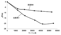
実施例1及び比較例1の電気二重層キャパシタの充放電を繰り返した。この充放電サイクル試験の間、初期の容量に対する各充放電サイクルでの容量変化率ΔCap(%)を測定した。その結果を図6に示す。図6に示すように、比較例1の電気二重層キャパシタでは、サイクル数を重ねるごとに容量が低下していき、4万サイクル達成時点で容量劣化が20%に達した。一方、実施例1の電気二重層キャパシタでは、サイクル数を重ねるごとに容量が低下する点では比較例1と同じであるが、1万数千サイクル経過後から容量低下が緩やかになり、4万サイクル達成時点では容量劣化が8.5%程度に止まった。
実施例1及び比較例1の電気二重層キャパシタの充放電を繰り返した。この充放電サイクル試験の間、初期の容量に対する各充放電サイクルでの容量変化率ΔCap(%)を測定した。その結果を図6に示す。図6に示すように、比較例1の電気二重層キャパシタでは、サイクル数を重ねるごとに容量が低下していき、4万サイクル達成時点で容量劣化が20%に達した。一方、実施例1の電気二重層キャパシタでは、サイクル数を重ねるごとに容量が低下する点では比較例1と同じであるが、1万数千サイクル経過後から容量低下が緩やかになり、4万サイクル達成時点では容量劣化が8.5%程度に止まった。
以上のイオン濃度分布と容量変化率の結果により、電極活物質層3を分割部31で小領域32に分断することにより、キャパシタ1内のイオンの濃淡差は緩和され、少なくともイオン濃度が0.3M以上を維持でき、容量劣化が抑制されたことが示された。
(実施例2)
実施例2の電気二重層キャパシタは、実施例1の電気二重層キャパシタにおける正極箔において電極活物質層3の小領域32の幅を30mmとし、分割部31の幅を5mmとし、負極箔において電極活物質層3の小領域32の幅を32mmとし、分割部31の幅を3mmとした。正極箔の幅は100mm、負極箔の幅は102mmとし、その他は実施例1と同一材料、同一方法及び同一条件で作製された。
実施例2の電気二重層キャパシタは、実施例1の電気二重層キャパシタにおける正極箔において電極活物質層3の小領域32の幅を30mmとし、分割部31の幅を5mmとし、負極箔において電極活物質層3の小領域32の幅を32mmとし、分割部31の幅を3mmとした。正極箔の幅は100mm、負極箔の幅は102mmとし、その他は実施例1と同一材料、同一方法及び同一条件で作製された。
(実施例3)
実施例3の電気二重層キャパシタは、実施例1の電気二重層キャパシタにおける正極箔において電極活物質層3の小領域32の幅を40mmとし、分割部31の幅を5mmとし、負極箔において電極活物質層3の小領域32の幅を42mmとし、分割部31の幅を3mmとした。正極箔の幅は130mm、負極箔の幅は132mmとし、その他は実施例1と同一材料、同一方法及び同一条件で作製された。
実施例3の電気二重層キャパシタは、実施例1の電気二重層キャパシタにおける正極箔において電極活物質層3の小領域32の幅を40mmとし、分割部31の幅を5mmとし、負極箔において電極活物質層3の小領域32の幅を42mmとし、分割部31の幅を3mmとした。正極箔の幅は130mm、負極箔の幅は132mmとし、その他は実施例1と同一材料、同一方法及び同一条件で作製された。
(実施例4)
実施例4の電気二重層キャパシタは、実施例1の電気二重層キャパシタにおける正極箔において電極活物質層3の小領域32の幅を50mmとし、分割部31の幅を5mmとし、負極箔において電極活物質層3の小領域32の幅を52mmとし、分割部31の幅を3mmとした。正極箔の幅は160mm、負極箔の幅は162mmとし、その他は実施例1と同一材料、同一方法及び同一条件で作製された。
実施例4の電気二重層キャパシタは、実施例1の電気二重層キャパシタにおける正極箔において電極活物質層3の小領域32の幅を50mmとし、分割部31の幅を5mmとし、負極箔において電極活物質層3の小領域32の幅を52mmとし、分割部31の幅を3mmとした。正極箔の幅は160mm、負極箔の幅は162mmとし、その他は実施例1と同一材料、同一方法及び同一条件で作製された。
(実施例5)
実施例5の電気二重層キャパシタは、正極箔において電極活物質層3の小領域32の幅を60mmとし、分割部31の幅を5mmとし、負極箔において電極活物質層3の小領域32の幅を62mmとし、分割部31の幅を3mmとした。正極箔の幅は190mm、負極箔の幅は192mmとし、その他は実施例1と同一材料、同一方法及び同一条件で作製された。
実施例5の電気二重層キャパシタは、正極箔において電極活物質層3の小領域32の幅を60mmとし、分割部31の幅を5mmとし、負極箔において電極活物質層3の小領域32の幅を62mmとし、分割部31の幅を3mmとした。正極箔の幅は190mm、負極箔の幅は192mmとし、その他は実施例1と同一材料、同一方法及び同一条件で作製された。
(実施例6)
実施例6の電気二重層キャパシタは、実施例1の電気二重層キャパシタにおける正極箔において電極活物質層3の小領域32の幅を70mmとし、分割部31の幅を5mmとし、負極箔において電極活物質層3の小領域32の幅を72mmとし、分割部31の幅を3mmとした。正極箔の幅は220mm、負極箔の幅は222mmとし、その他は実施例1と同一材料、同一方法及び同一条件で作製された。
実施例6の電気二重層キャパシタは、実施例1の電気二重層キャパシタにおける正極箔において電極活物質層3の小領域32の幅を70mmとし、分割部31の幅を5mmとし、負極箔において電極活物質層3の小領域32の幅を72mmとし、分割部31の幅を3mmとした。正極箔の幅は220mm、負極箔の幅は222mmとし、その他は実施例1と同一材料、同一方法及び同一条件で作製された。
(容量変化率の確認)
実施例1乃至6の電気二重層キャパシタの充放電を繰り返した。この充放電サイクル試験の間、初期の容量に対する各充放電サイクルでの容量変化率ΔCap(%)を測定した。その結果を表2に示す。
実施例1乃至6の電気二重層キャパシタの充放電を繰り返した。この充放電サイクル試験の間、初期の容量に対する各充放電サイクルでの容量変化率ΔCap(%)を測定した。その結果を表2に示す。
(表2)
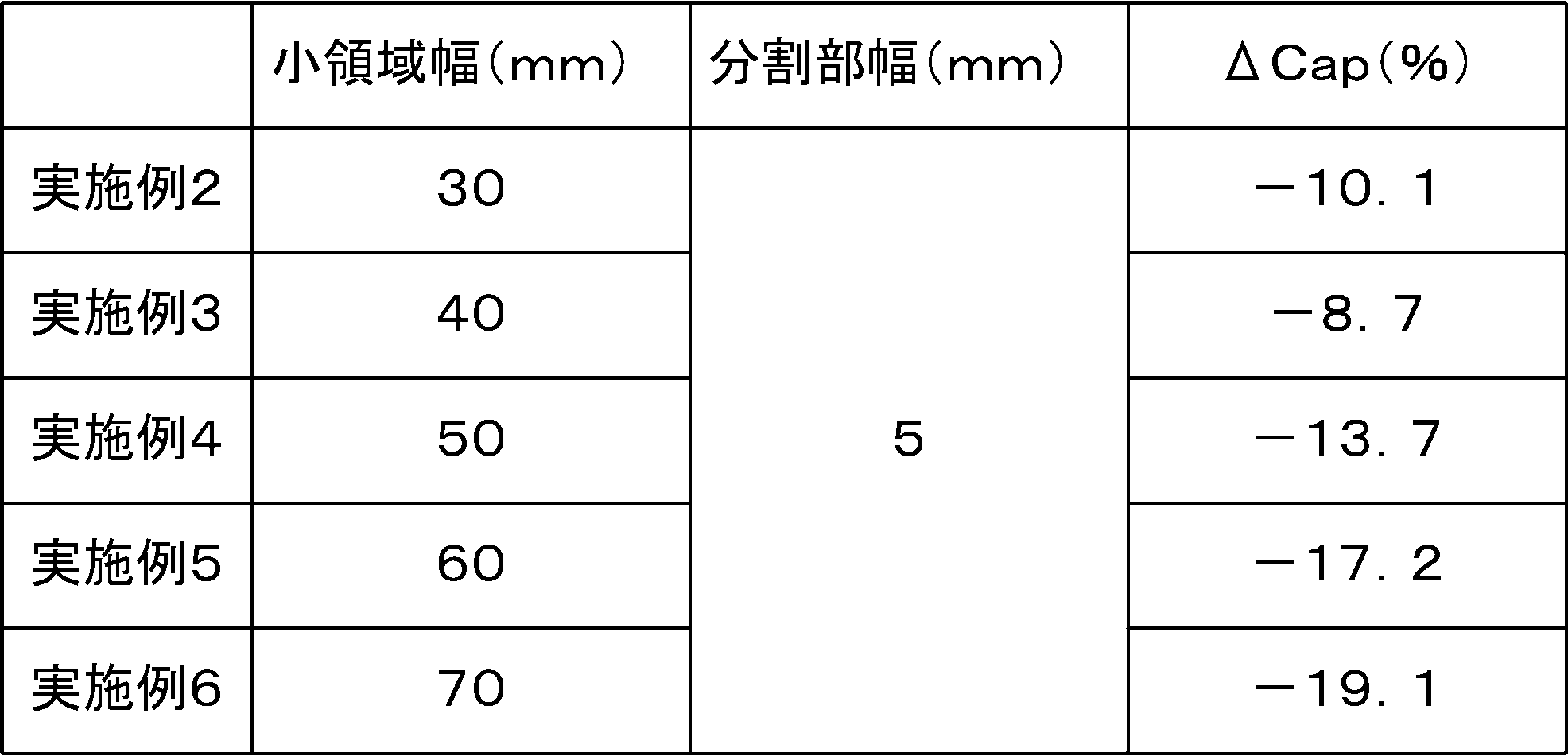
表2に示すように、4万回の充放電を繰り返すと、容量劣化は、小領域32の幅が30mmの実施例2は10.1%、小領域32の幅が40mmの実施例3は8.7%、小領域32の幅が50mmの実施例4は13.7%、小領域32の幅が60mmの実施例5は17.2%、小領域32の幅が70mmの実施例6は19.1%であった。
これにより、小領域32の幅が狭くなると容量劣化が緩和されることが確認された。また小領域32の幅が50mm以下では、1万サイクル近辺で容量低下が緩やかになり、4万サイクル達成時点での容量劣化の抑制効果に大きく貢献していることが確認された。従って、小領域32の幅は50mm以下が望ましい。
(実施例7乃至実施例10)
実施例7乃至実施例10の電気二重層キャパシタは、実施例1の電気二重層キャパシタにおける正極箔及び負極箔において電極活物質層3の小領域32の幅及び分割部31の幅を表3に示す寸法に設定して作製されたものであり、その他は実施例1と同一材料、同一方法及び同一条件で作製された。
実施例7乃至実施例10の電気二重層キャパシタは、実施例1の電気二重層キャパシタにおける正極箔及び負極箔において電極活物質層3の小領域32の幅及び分割部31の幅を表3に示す寸法に設定して作製されたものであり、その他は実施例1と同一材料、同一方法及び同一条件で作製された。
なお、実施例7の電気二重層キャパシタでは、負極箔側の小領域32が正極箔側の小領域32よりも狭く、正極箔側の小領域32に負極側の小領域32と正対していない非対向領域が存在している点で実施例1と異なっている。
即ち、実施例7の電気二重層キャパシタでは、正極箔の集電体7に対し、1mm間隔で40mm幅のスラリーを集電体7の長手方向に沿って塗布し、乾燥させた。その結果、40mm幅の小領域32が三条分形成され、三条の小領域32が1mm幅の2条の分割部31で分断された正極箔が形成された。
この負極箔の集電体7に対し、3mm間隔で38mm幅のスラリーを集電体7の長手方向に沿って塗布し、乾燥させた。その結果、38mm幅の小領域32が3条分形成され、3条の小領域32が3mm幅の2条の分割部31で分断された負極箔が形成された。従って、正極箔の小領域32のうち2mm幅が負極箔の小領域32と正対していない非対向領域となり、三条の小領域32では、合計6mmの非対向領域が形成される。
(容量変化率の確認)
実施例7乃至10及び比較例1の電気二重層キャパシタの充放電を繰り返した。この充放電サイクル試験の間、初期の容量に対する各充放電サイクルでの容量変化率ΔCap(%)を測定した。その結果を表3に示す。
実施例7乃至10及び比較例1の電気二重層キャパシタの充放電を繰り返した。この充放電サイクル試験の間、初期の容量に対する各充放電サイクルでの容量変化率ΔCap(%)を測定した。その結果を表3に示す。
(表3)
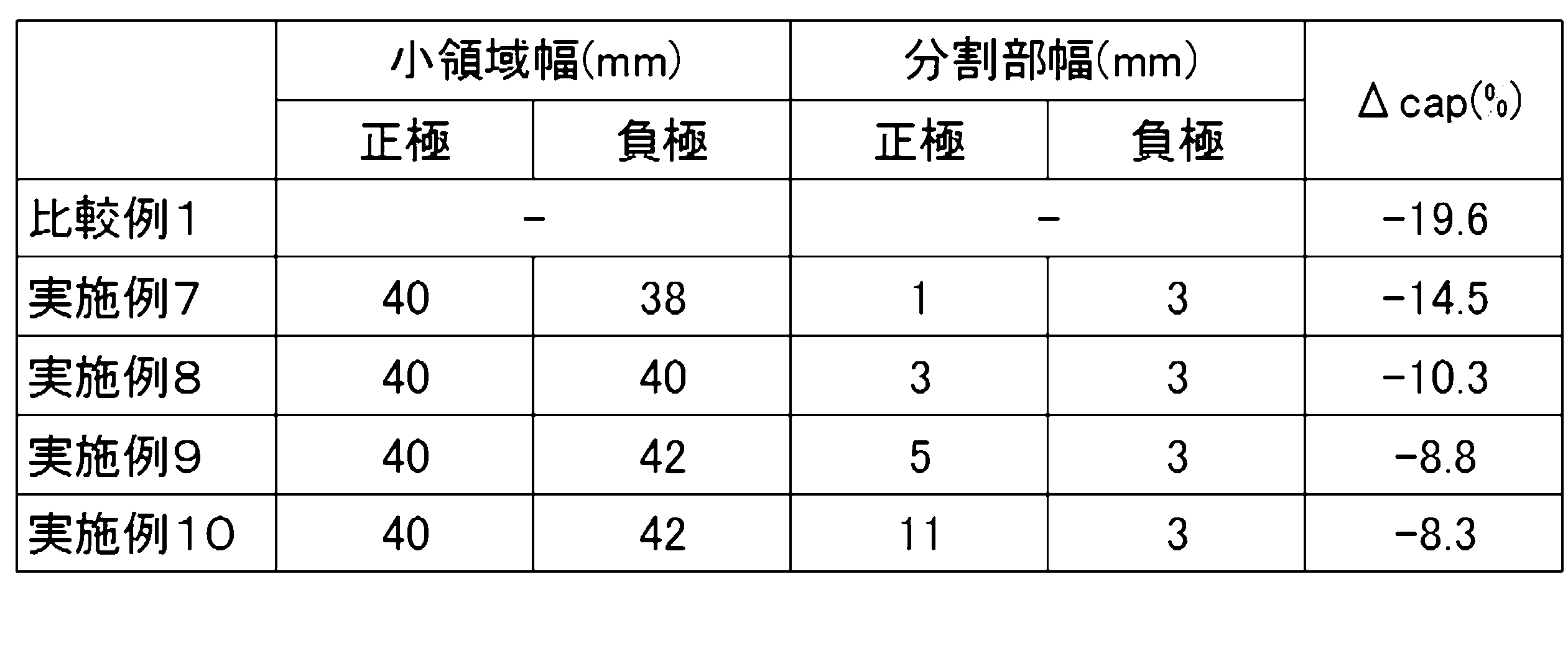
表3に示すように、4万回の充放電を繰り返すと、容量劣化は、比較例1が19.6%であるのに対し、正極側の分割部31の幅が1mmの実施例7は14.5%、分割部31の幅が3mmの実施例8は10.3%、分割部31の幅が5mmの実施例9は8.8%、分割部31の幅が11mmの実施例10は8.3%であった。
これにより、分割部31があれば容量劣化が抑制されることが確認された。そして、分割部31の幅が拡がるほど、容量劣化の抑制効果が高まることが確認された。分割部31の幅が拡がれば小領域32間をイオンが移動し難くなるためと考えられる。なお、分割部31の幅については製造上のバラツキを考慮すると3mm以上が望ましい。
また、実施例7の電気二重層キャパシタは、実施例8と比べれば容量劣化の程度が大きく、これは正極箔の小領域32に非対向領域が存在することが要因となって劣化が生じると考えられる。正極箔の小領域32に負極箔の電極活物質層3と正対しない部分が無いように、つまり、負極箔の小領域によってセパレータを介して対向する正極箔の小領域が覆われていることが望ましいことが確認された。
(実施例11)
正極箔及び負極箔の分断部を6mm幅とし、正極側及び負極側の分極性電極の小領域の幅を20mmから60mmまで10mm刻みで変えた電気二重層キャパシタを作製し、充放電サイクル試験4万回経過後の容量を測定した。この電気二重層キャパシタは、φ63.5×172Lの巻回形の電気二重層キャパシタであり、定格電圧2.5V、定格容量は3600Fのものを用いた。その結果を表4に示す。
正極箔及び負極箔の分断部を6mm幅とし、正極側及び負極側の分極性電極の小領域の幅を20mmから60mmまで10mm刻みで変えた電気二重層キャパシタを作製し、充放電サイクル試験4万回経過後の容量を測定した。この電気二重層キャパシタは、φ63.5×172Lの巻回形の電気二重層キャパシタであり、定格電圧2.5V、定格容量は3600Fのものを用いた。その結果を表4に示す。
(表4)

表4に示すように、比較例1の電気二重層キャパシタでは、4万回のサイクル試験後においては、容量劣化により容量は2880Fとなる。これに対して、小領域32の幅が30mm以上になると、容量は比較例1の2880Fを超えることがわかった。従って、小領域32の幅は30mm以上が望ましいことが確認された。
(実施例12)
実施例12の電気二重層キャパシタは、正極箔の電極活物質層3に実施例1と同じ分割部31を設け、電極活物質層3を小領域32で分割した点は、実施例1と同じであるが、負極箔の電極活物質層3には分割部31を設けず、即ち比較例1の負極箔を用いた点で実施例1と異なり、その他は実施例1と同一材料、同一方法及び同一条件で作製された。
実施例12の電気二重層キャパシタは、正極箔の電極活物質層3に実施例1と同じ分割部31を設け、電極活物質層3を小領域32で分割した点は、実施例1と同じであるが、負極箔の電極活物質層3には分割部31を設けず、即ち比較例1の負極箔を用いた点で実施例1と異なり、その他は実施例1と同一材料、同一方法及び同一条件で作製された。
(容量変化率の確認)
実施例1、実施例12及び比較例1の電気二重層キャパシタの充放電を繰り返した。この充放電サイクル試験の間、初期の容量に対する各充放電サイクルでの容量変化率ΔCap(%)を測定した。その結果を図7に示す。図7に示すように、正極箔の電極活物質層3のみを分割部31で小領域32に分断した実施例10の電気二重層キャパシタは、実施例1と変わらず、擬似容量劣化を抑制することが確認された。
実施例1、実施例12及び比較例1の電気二重層キャパシタの充放電を繰り返した。この充放電サイクル試験の間、初期の容量に対する各充放電サイクルでの容量変化率ΔCap(%)を測定した。その結果を図7に示す。図7に示すように、正極箔の電極活物質層3のみを分割部31で小領域32に分断した実施例10の電気二重層キャパシタは、実施例1と変わらず、擬似容量劣化を抑制することが確認された。
(実施例13)
正極箔及び負極箔に分割部31を形成した実施例13に係るハイブリッドキャパシタを作製した。この実施例13のハイブリッドキャパシタは、正極箔は実施例1と同じものを用い、また正極箔及び負極箔の小領域32の数及び幅、並びに分割部31の数及び幅は実施例1と同じである。但し、この実施例13のハイブリッドキャパシタは、負極箔にチタン酸リチウムを電極活物質層3とするファラデー反応電極を用いた。電解液には、1.5MのLiBF4を溶質とするプロピレンカーボネート溶液を用いた。
正極箔及び負極箔に分割部31を形成した実施例13に係るハイブリッドキャパシタを作製した。この実施例13のハイブリッドキャパシタは、正極箔は実施例1と同じものを用い、また正極箔及び負極箔の小領域32の数及び幅、並びに分割部31の数及び幅は実施例1と同じである。但し、この実施例13のハイブリッドキャパシタは、負極箔にチタン酸リチウムを電極活物質層3とするファラデー反応電極を用いた。電解液には、1.5MのLiBF4を溶質とするプロピレンカーボネート溶液を用いた。
即ち、チタン酸リチウム粉体に対して5wt%のポリフッ化ビニリデンと適量のN-メチルピロリドンを加えて十分に混練してスラリーを形成し、表面にカーボンコート層を形成した集電体7であるアルミニウム箔上に塗布し、乾燥して、チタン酸リチウムを有する電極を得た。
チタン酸リチウムを含有するスラリーは、筒軸方向に146mmの幅を有する集電体7に、筒軸方向に42mm幅のスラリーを集電体7の長手方向に沿って塗布した。このスラリーは、筒軸方向に5mm間隔を空けて、三条分平行に塗布した。即ち、負極箔の集電体7に形成される電極活物質層3は、2本の5mm幅の分割部31によって、各々が42mm幅を有する上部域Uと中腹域Mと下部域Dの各小領域32に分割された。
尚、正極箔については、筒軸方向に144mmの幅を有する集電体7に、筒軸方向に7mmの間隔を空けて、三条分平行に塗布した。即ち、正極箔の集電体7に形成される電極活物質層3は、2本の7mm幅の分割部31によって、各々が40mm幅を有する上部域Uと中腹域Mと下部域Dの各小領域32に分割された。
(比較例2)
比較例2のハイブリッドキャパシタは、分割部31が未形成な点で、実施例13のハイブリッドキャパシタと異なる。その他は、実施例13と同一材料、同一方法及び同一条件で比較例2のハイブリッドキャパシタを作製した。
比較例2のハイブリッドキャパシタは、分割部31が未形成な点で、実施例13のハイブリッドキャパシタと異なる。その他は、実施例13と同一材料、同一方法及び同一条件で比較例2のハイブリッドキャパシタを作製した。
(容量変化率の確認)
実施例13及び比較例2のハイブリッドキャパシタの充放電を繰り返した。この充放電サイクル試験の間、初期の容量に対する各充放電サイクルでの容量変化率ΔCap(%)を測定した。その結果は次の通りである。即ち、比較例2のハイブリッドキャパシタでは、サイクル数を重ねるごとに容量が低下していき、4万サイクル達成時点で容量劣化が18.5%に達した。一方、実施例13のハイブリッドキャパシタでは、4万サイクル達成時点では容量劣化が8.9%程度に止まった。
実施例13及び比較例2のハイブリッドキャパシタの充放電を繰り返した。この充放電サイクル試験の間、初期の容量に対する各充放電サイクルでの容量変化率ΔCap(%)を測定した。その結果は次の通りである。即ち、比較例2のハイブリッドキャパシタでは、サイクル数を重ねるごとに容量が低下していき、4万サイクル達成時点で容量劣化が18.5%に達した。一方、実施例13のハイブリッドキャパシタでは、4万サイクル達成時点では容量劣化が8.9%程度に止まった。
以上のイオン濃度分布と容量変化率の結果により、電極活物質層3を分割部31で小領域32に分断することにより、電気二重層キャパシタであっても、ハイブリッドキャパシタであっても、イオンの濃淡差が緩和されて容量劣化が抑制されたことが示された。
1 電極箔
3 電極活物質層
31 分割部
32 小領域
7 集電体
8 押圧部
3 電極活物質層
31 分割部
32 小領域
7 集電体
8 押圧部
Claims (12)
- 集電体と、
前記集電体の表面に形成された電極活物質層と、
前記電極活物質層を小領域に分割する分割部と、
を備えること、
を特徴とするキャパシタ用電極箔。 - 前記電極活物質層は、帯形状を有し、前記分割部によって、前記電極活物質層を帯長手方向に沿って延びる帯状の小領域に分割され、
前記小領域は、前記分割部と直交する方向に沿った帯幅方向の長さが30mm以上50mm以下であること、
を特徴とする請求項1記載のキャパシタ用電極箔。 - 前記電極活物質層は帯形状を有し、
前記分割部は、前記電極活物質層の帯長手方向に延びて、前記電極活物質層を帯長手方向に沿って延びる帯状の小領域に分割する溝であり、幅が1mm以上であること、
を特徴とする請求項1記載のキャパシタ用電極箔。 - 請求項1乃至3の何れかに記載のキャパシタ用電極箔と電解液とを備えること、
を特徴とするキャパシタ。 - 充放電サイクル試験4万回経過時の帯形状のキャパシタ用電極箔の幅手端部のイオン濃度(M)が、0.3以上であること、
を特徴とする請求項4に記載のキャパシタ。 - 少なくとも正極側に前記キャパシタ用電極箔を備えること、
を特徴とする請求項4又は5記載のキャパシタ。 - 正極側にのみ前記キャパシタ用電極箔を備えること、
を特徴とする請求項4又は5記載のキャパシタ。 - 正極側に前記分割部を有する前記キャパシタ用電極箔を備え、
前記正極側の前記小領域は、対向する負極の活物質層で覆われていること、
を特徴とする請求項4乃至7の何れかに記載のキャパシタ。 - 正極と負極の両方に前記分割部を有する前記キャパシタ用電極箔を備え、
前記正極の前記小領域の幅は、前記負極の前記小領域の幅よりも狭く、
前記正極の前記小領域は、対向する前記負極の前記小領域で覆われていること、
を特徴とする請求項4乃至6の何れかに記載のキャパシタ。 - 正極及び負極の両方に前記キャパシタ用電極箔を用い、この電極箔が分極性電極を有すること、
を特徴とする請求項4乃至9の何れかに記載のキャパシタ。 - 正極側及び負極の両方に前記キャパシタ用電極箔を用い、
正極側のキャパシタ用電極箔は、分極性電極を有し、
負極側のキャパシタ用電極箔は、リチウムイオンを吸蔵及び放出する金属化合物粒子の層により成る電極を有すること、
を特徴とする請求項4乃至9の何れかに記載のキャパシタ。 - 前記キャパシタ用電極箔をセパレータを介して巻回され、電解液が含有されたキャパシタ素子と、
前記キャパシタ素子を収納する外装ケースと、
前記外装ケースの側面を押圧して前記キャパシタ素子を固定する押圧部と、
を備え、
前記押圧部は、前記分割部の位置と一致せず、前記小領域の位置に形成されること、
を特徴とする請求項4乃至11の何れかに記載のキャパシタ。
Priority Applications (2)
| Application Number | Priority Date | Filing Date | Title |
|---|---|---|---|
| US16/624,857 US20210296055A1 (en) | 2017-06-20 | 2018-05-29 | Capacitor electrode foil and capacitor |
| CN201880040204.4A CN110770862A (zh) | 2017-06-20 | 2018-05-29 | 电容器用电极箔及电容器 |
Applications Claiming Priority (2)
| Application Number | Priority Date | Filing Date | Title |
|---|---|---|---|
| JP2017120915A JP2019009159A (ja) | 2017-06-20 | 2017-06-20 | キャパシタ用電極箔及びキャパシタ |
| JP2017-120915 | 2017-06-20 |
Publications (1)
| Publication Number | Publication Date |
|---|---|
| WO2018235546A1 true WO2018235546A1 (ja) | 2018-12-27 |
Family
ID=64737468
Family Applications (1)
| Application Number | Title | Priority Date | Filing Date |
|---|---|---|---|
| PCT/JP2018/020610 Ceased WO2018235546A1 (ja) | 2017-06-20 | 2018-05-29 | キャパシタ用電極箔及びキャパシタ |
Country Status (4)
| Country | Link |
|---|---|
| US (1) | US20210296055A1 (ja) |
| JP (1) | JP2019009159A (ja) |
| CN (1) | CN110770862A (ja) |
| WO (1) | WO2018235546A1 (ja) |
Families Citing this family (1)
| Publication number | Priority date | Publication date | Assignee | Title |
|---|---|---|---|---|
| US20210156051A1 (en) * | 2019-11-21 | 2021-05-27 | The Regents Of The University Of California | Coaxial cellulose-based aerogel fibers |
Citations (5)
| Publication number | Priority date | Publication date | Assignee | Title |
|---|---|---|---|---|
| JP2006287174A (ja) * | 2005-03-31 | 2006-10-19 | Korchip Co Ltd | 高電圧電気二重層キャパシタ |
| JP2007067285A (ja) * | 2005-09-01 | 2007-03-15 | Hitachi Aic Inc | 電気二重層キャパシタ |
| JP2013041894A (ja) * | 2011-08-11 | 2013-02-28 | Nippon Chemicon Corp | コンデンサ、その製造方法及び製造プログラム |
| JP2014212242A (ja) * | 2013-04-19 | 2014-11-13 | 太陽誘電株式会社 | 電気化学デバイス |
| JP2016115912A (ja) * | 2014-12-16 | 2016-06-23 | 日本ケミコン株式会社 | 金属化合物粒子群の製造方法、金属化合物粒子群及び金属化合物粒子群を含む蓄電デバイス用電極 |
Family Cites Families (2)
| Publication number | Priority date | Publication date | Assignee | Title |
|---|---|---|---|---|
| US6493206B1 (en) * | 1999-09-20 | 2002-12-10 | High Energy Corp. | Electrical capacitor with improved heat transfer characteristics |
| CN101699589B (zh) * | 2009-11-18 | 2011-04-20 | 凯迈嘉华(洛阳)新能源有限公司 | 一种超级电容器电极极片的制备方法 |
-
2017
- 2017-06-20 JP JP2017120915A patent/JP2019009159A/ja active Pending
-
2018
- 2018-05-29 CN CN201880040204.4A patent/CN110770862A/zh active Pending
- 2018-05-29 WO PCT/JP2018/020610 patent/WO2018235546A1/ja not_active Ceased
- 2018-05-29 US US16/624,857 patent/US20210296055A1/en not_active Abandoned
Patent Citations (5)
| Publication number | Priority date | Publication date | Assignee | Title |
|---|---|---|---|---|
| JP2006287174A (ja) * | 2005-03-31 | 2006-10-19 | Korchip Co Ltd | 高電圧電気二重層キャパシタ |
| JP2007067285A (ja) * | 2005-09-01 | 2007-03-15 | Hitachi Aic Inc | 電気二重層キャパシタ |
| JP2013041894A (ja) * | 2011-08-11 | 2013-02-28 | Nippon Chemicon Corp | コンデンサ、その製造方法及び製造プログラム |
| JP2014212242A (ja) * | 2013-04-19 | 2014-11-13 | 太陽誘電株式会社 | 電気化学デバイス |
| JP2016115912A (ja) * | 2014-12-16 | 2016-06-23 | 日本ケミコン株式会社 | 金属化合物粒子群の製造方法、金属化合物粒子群及び金属化合物粒子群を含む蓄電デバイス用電極 |
Also Published As
| Publication number | Publication date |
|---|---|
| JP2019009159A (ja) | 2019-01-17 |
| US20210296055A1 (en) | 2021-09-23 |
| CN110770862A (zh) | 2020-02-07 |
Similar Documents
| Publication | Publication Date | Title |
|---|---|---|
| KR101138562B1 (ko) | 전극 구조체 및 그 제조 방법, 그리고 상기 전극 구조체를 구비하는 에너지 저장 장치 | |
| KR102037266B1 (ko) | 전극 구조물 및 이를 구비하는 에너지 저장 장치 | |
| US10504661B2 (en) | Hybrid capacitor and separator for hybrid capacitors | |
| JP6816395B2 (ja) | 電気二重層キャパシタ | |
| WO2019234977A1 (ja) | 半固体電解質層及び二次電池 | |
| US20030137798A1 (en) | Electric double layer capacitor | |
| US7173807B2 (en) | Electric double layer capacitor | |
| JP2007266064A (ja) | 電気二重層キャパシタ | |
| JP6010763B2 (ja) | 電気化学キャパシタ | |
| JP2016197649A (ja) | 電気二重層キャパシタ用セパレータおよび電気二重層キャパシタ | |
| KR101138522B1 (ko) | 전극 구조체 및 이를 구비하는 리튬 이온 캐패시터 | |
| WO2018235546A1 (ja) | キャパシタ用電極箔及びキャパシタ | |
| JPWO2008018326A1 (ja) | 電気二重層キャパシタ用非水系電解液およびそれを用いた電気二重層キャパシタ | |
| US20230111774A1 (en) | Solid electrolyte, electricity storage device and method for producing solid electrolyte | |
| JP2013197535A (ja) | 電解液及び電気二重層キャパシタ | |
| JP2016197647A (ja) | ハイブリッドキャパシタ用セパレータおよびハイブリッドキャパシタ | |
| JP2016197648A (ja) | 電気二重層キャパシタ | |
| JP2014220327A (ja) | 蓄電デバイス用電極、蓄電デバイスおよび蓄電デバイス用電極の製造方法 | |
| US20240283019A1 (en) | Solid electrolyte, electricity storage device and method for producing solid electrolyte | |
| EP4451301A1 (en) | Electric double layer capacitor and method for producing same | |
| JP2024082269A (ja) | 蓄電デバイス及び蓄電デバイスの製造方法 | |
| WO2025018312A1 (ja) | 電気二重層キャパシタ用電解液、及び電気二重層キャパシタ | |
| KR101098236B1 (ko) | 슈퍼커패시터 셀 어레이 제조방법 | |
| JP2002222739A (ja) | 電気二重層キャパシタ及びそのための電解液 |
Legal Events
| Date | Code | Title | Description |
|---|---|---|---|
| 121 | Ep: the epo has been informed by wipo that ep was designated in this application |
Ref document number: 18819720 Country of ref document: EP Kind code of ref document: A1 |
|
| NENP | Non-entry into the national phase |
Ref country code: DE |
|
| 122 | Ep: pct application non-entry in european phase |
Ref document number: 18819720 Country of ref document: EP Kind code of ref document: A1 |