WO2018235244A1 - ラインパイプ用アズロール電縫鋼管及び熱延鋼板 - Google Patents
ラインパイプ用アズロール電縫鋼管及び熱延鋼板 Download PDFInfo
- Publication number
- WO2018235244A1 WO2018235244A1 PCT/JP2017/023086 JP2017023086W WO2018235244A1 WO 2018235244 A1 WO2018235244 A1 WO 2018235244A1 JP 2017023086 W JP2017023086 W JP 2017023086W WO 2018235244 A1 WO2018235244 A1 WO 2018235244A1
- Authority
- WO
- WIPO (PCT)
- Prior art keywords
- less
- pipe
- hot
- steel pipe
- rolled steel
- Prior art date
Links
Images


Classifications
-
- C—CHEMISTRY; METALLURGY
- C22—METALLURGY; FERROUS OR NON-FERROUS ALLOYS; TREATMENT OF ALLOYS OR NON-FERROUS METALS
- C22C—ALLOYS
- C22C38/00—Ferrous alloys, e.g. steel alloys
- C22C38/001—Ferrous alloys, e.g. steel alloys containing N
-
- C—CHEMISTRY; METALLURGY
- C21—METALLURGY OF IRON
- C21D—MODIFYING THE PHYSICAL STRUCTURE OF FERROUS METALS; GENERAL DEVICES FOR HEAT TREATMENT OF FERROUS OR NON-FERROUS METALS OR ALLOYS; MAKING METAL MALLEABLE, e.g. BY DECARBURISATION OR TEMPERING
- C21D6/00—Heat treatment of ferrous alloys
- C21D6/005—Heat treatment of ferrous alloys containing Mn
-
- C—CHEMISTRY; METALLURGY
- C21—METALLURGY OF IRON
- C21D—MODIFYING THE PHYSICAL STRUCTURE OF FERROUS METALS; GENERAL DEVICES FOR HEAT TREATMENT OF FERROUS OR NON-FERROUS METALS OR ALLOYS; MAKING METAL MALLEABLE, e.g. BY DECARBURISATION OR TEMPERING
- C21D8/00—Modifying the physical properties by deformation combined with, or followed by, heat treatment
- C21D8/02—Modifying the physical properties by deformation combined with, or followed by, heat treatment during manufacturing of plates or strips
- C21D8/0205—Modifying the physical properties by deformation combined with, or followed by, heat treatment during manufacturing of plates or strips of ferrous alloys
-
- C—CHEMISTRY; METALLURGY
- C21—METALLURGY OF IRON
- C21D—MODIFYING THE PHYSICAL STRUCTURE OF FERROUS METALS; GENERAL DEVICES FOR HEAT TREATMENT OF FERROUS OR NON-FERROUS METALS OR ALLOYS; MAKING METAL MALLEABLE, e.g. BY DECARBURISATION OR TEMPERING
- C21D8/00—Modifying the physical properties by deformation combined with, or followed by, heat treatment
- C21D8/02—Modifying the physical properties by deformation combined with, or followed by, heat treatment during manufacturing of plates or strips
- C21D8/0221—Modifying the physical properties by deformation combined with, or followed by, heat treatment during manufacturing of plates or strips characterised by the working steps
- C21D8/0226—Hot rolling
-
- C—CHEMISTRY; METALLURGY
- C21—METALLURGY OF IRON
- C21D—MODIFYING THE PHYSICAL STRUCTURE OF FERROUS METALS; GENERAL DEVICES FOR HEAT TREATMENT OF FERROUS OR NON-FERROUS METALS OR ALLOYS; MAKING METAL MALLEABLE, e.g. BY DECARBURISATION OR TEMPERING
- C21D8/00—Modifying the physical properties by deformation combined with, or followed by, heat treatment
- C21D8/10—Modifying the physical properties by deformation combined with, or followed by, heat treatment during manufacturing of tubular bodies
- C21D8/105—Modifying the physical properties by deformation combined with, or followed by, heat treatment during manufacturing of tubular bodies of ferrous alloys
-
- C—CHEMISTRY; METALLURGY
- C21—METALLURGY OF IRON
- C21D—MODIFYING THE PHYSICAL STRUCTURE OF FERROUS METALS; GENERAL DEVICES FOR HEAT TREATMENT OF FERROUS OR NON-FERROUS METALS OR ALLOYS; MAKING METAL MALLEABLE, e.g. BY DECARBURISATION OR TEMPERING
- C21D9/00—Heat treatment, e.g. annealing, hardening, quenching or tempering, adapted for particular articles; Furnaces therefor
- C21D9/08—Heat treatment, e.g. annealing, hardening, quenching or tempering, adapted for particular articles; Furnaces therefor for tubular bodies or pipes
-
- C—CHEMISTRY; METALLURGY
- C22—METALLURGY; FERROUS OR NON-FERROUS ALLOYS; TREATMENT OF ALLOYS OR NON-FERROUS METALS
- C22C—ALLOYS
- C22C38/00—Ferrous alloys, e.g. steel alloys
- C22C38/02—Ferrous alloys, e.g. steel alloys containing silicon
-
- C—CHEMISTRY; METALLURGY
- C22—METALLURGY; FERROUS OR NON-FERROUS ALLOYS; TREATMENT OF ALLOYS OR NON-FERROUS METALS
- C22C—ALLOYS
- C22C38/00—Ferrous alloys, e.g. steel alloys
- C22C38/04—Ferrous alloys, e.g. steel alloys containing manganese
-
- C—CHEMISTRY; METALLURGY
- C22—METALLURGY; FERROUS OR NON-FERROUS ALLOYS; TREATMENT OF ALLOYS OR NON-FERROUS METALS
- C22C—ALLOYS
- C22C38/00—Ferrous alloys, e.g. steel alloys
- C22C38/06—Ferrous alloys, e.g. steel alloys containing aluminium
-
- C—CHEMISTRY; METALLURGY
- C22—METALLURGY; FERROUS OR NON-FERROUS ALLOYS; TREATMENT OF ALLOYS OR NON-FERROUS METALS
- C22C—ALLOYS
- C22C38/00—Ferrous alloys, e.g. steel alloys
- C22C38/12—Ferrous alloys, e.g. steel alloys containing tungsten, tantalum, molybdenum, vanadium, or niobium
-
- C—CHEMISTRY; METALLURGY
- C22—METALLURGY; FERROUS OR NON-FERROUS ALLOYS; TREATMENT OF ALLOYS OR NON-FERROUS METALS
- C22C—ALLOYS
- C22C38/00—Ferrous alloys, e.g. steel alloys
- C22C38/14—Ferrous alloys, e.g. steel alloys containing titanium or zirconium
-
- C—CHEMISTRY; METALLURGY
- C21—METALLURGY OF IRON
- C21D—MODIFYING THE PHYSICAL STRUCTURE OF FERROUS METALS; GENERAL DEVICES FOR HEAT TREATMENT OF FERROUS OR NON-FERROUS METALS OR ALLOYS; MAKING METAL MALLEABLE, e.g. BY DECARBURISATION OR TEMPERING
- C21D2211/00—Microstructure comprising significant phases
- C21D2211/002—Bainite
-
- C—CHEMISTRY; METALLURGY
- C21—METALLURGY OF IRON
- C21D—MODIFYING THE PHYSICAL STRUCTURE OF FERROUS METALS; GENERAL DEVICES FOR HEAT TREATMENT OF FERROUS OR NON-FERROUS METALS OR ALLOYS; MAKING METAL MALLEABLE, e.g. BY DECARBURISATION OR TEMPERING
- C21D2211/00—Microstructure comprising significant phases
- C21D2211/005—Ferrite
-
- C—CHEMISTRY; METALLURGY
- C21—METALLURGY OF IRON
- C21D—MODIFYING THE PHYSICAL STRUCTURE OF FERROUS METALS; GENERAL DEVICES FOR HEAT TREATMENT OF FERROUS OR NON-FERROUS METALS OR ALLOYS; MAKING METAL MALLEABLE, e.g. BY DECARBURISATION OR TEMPERING
- C21D6/00—Heat treatment of ferrous alloys
- C21D6/001—Heat treatment of ferrous alloys containing Ni
-
- C—CHEMISTRY; METALLURGY
- C21—METALLURGY OF IRON
- C21D—MODIFYING THE PHYSICAL STRUCTURE OF FERROUS METALS; GENERAL DEVICES FOR HEAT TREATMENT OF FERROUS OR NON-FERROUS METALS OR ALLOYS; MAKING METAL MALLEABLE, e.g. BY DECARBURISATION OR TEMPERING
- C21D6/00—Heat treatment of ferrous alloys
- C21D6/008—Heat treatment of ferrous alloys containing Si
Definitions
- the present disclosure relates to azroll ERW steel pipe for line pipe and a hot rolled steel sheet.
- Hot-rolled steel sheet consisting of Fe and an unavoidable impurity element Of the pro-eutectoid ferrite fraction of 3% or more and 20% or less, the low-temperature transformation phase and pearlite of 1% or less, in the microstructure at a depth of half thickness from the surface of the steel sheet
- the total number average crystal grain size is 1 ⁇ m to 2.5 ⁇ m and the area average grain size is 3 ⁇ m to 9 ⁇ m, the standard deviation of the area average grain size is 0.8 ⁇ m to 2.3 ⁇ m
- the steel sheet surface To steel plate at a depth of half thickness Hot-rolled steel sheet is disclosed which not less than 1.1 ⁇ 211 ⁇ direction and a ⁇ 111 ⁇ direction of the reflected X-ray intensity ratio ⁇ 211 ⁇ / ⁇ 111 ⁇ against a plane parallel to the plane.
- Patent Document 1 describes that the hot-rolled steel plate described in the same document can be
- Patent Document 1 International Publication No. 2012/002481
- welded steel pipes are manufactured using a UOE steel pipe manufactured using a thick plate (for example, a thick plate having a thickness of 30 mm or more) or a hot coil made of a hot-rolled steel plate
- a thick plate for example, a thick plate having a thickness of 30 mm or more
- a hot coil made of a hot-rolled steel plate
- the electric resistance welded steel pipe or spiral steel pipe is used.
- Low-temperature toughness (hereinafter, also simply referred to as “low-temperature toughness”) evaluated by DWTT (Drop Weight Tear Test) may be required for steel pipes for line pipes. More specifically, the lower the DWTT guaranteed temperature, which is the lowest temperature at which the ductility fracture ratio is 85% or more, the better the low temperature toughness.
- Low temperature toughness generally tends to be required for thick walled line pipe steel pipes.
- the thick wall thickness of the steel pipe for line pipe is advantageous in terms of strength, it is disadvantageous in terms of low-temperature toughness. Therefore, in the field of relatively thick UOE steel pipes, low temperature toughness has conventionally been noted. On the other hand, in the field of ERW steel pipe with relatively thin wall thickness, low temperature toughness has hardly been noted.
- the thick plate process for producing a thick plate which is a material of UOE steel pipe has a relatively high degree of freedom in production conditions.
- low temperature rolling can be easily performed, and complicated controlled cooling can be easily performed for cooling after rolling. Therefore, in the field of UOE steel pipe, in order to improve the low temperature toughness of the UOE steel pipe, fine adjustment of metal structure by cold rolling, complicated controlled cooling, etc. was generally performed in the thick plate process. .
- the hot rolling process for manufacturing the hot coil (in detail, the hot rolled steel sheet in the form of the hot coil) which is the material of the ERW steel pipe is a thick plate from the restriction on the equipment with emphasis on productivity.
- the degree of freedom of the manufacturing conditions is low compared to the process.
- the hot rolled steel sheet after rolling is cooled to, for example, a winding temperature (CT) of about 400 to 600 ° C., and then wound into a coil.
- CT winding temperature
- the hot rolling process is difficult to perform cold rolling and complicated controlled cooling after rolling as compared to the thick plate process. Under these circumstances, in the field of ERW steel pipe, it has not been possible to come to the idea itself of fine-tuning the metal structure in the hot rolling process to improve the low temperature toughness of the ERW pipe.
- the UOE steel pipe which is a thick plate and its final product
- the electric resistance welded steel pipe which is a hot-rolled steel plate and its final product
- the problem that is, the low temperature toughness
- the cooling rate at the time of air cooling is relatively fast.
- the cooling rate at the time of air cooling is relatively slow.
- the metal structure may be substantially tempered while being air cooled in the form of the hot coil.
- Patent Document 1 is one of the few documents focusing on the low temperature toughness of a hot rolled steel sheet that may be used for the production of a ERW steel pipe. However, there are cases where it is required to further improve the low temperature toughness to the technology disclosed in Patent Document 1.
- An object of the present disclosure is to provide azroll ERW steel pipe for line pipe excellent in low temperature toughness evaluated by DWTT, and a hot-rolled steel plate suitable for manufacturing the azroll ERW steel pipe for line pipe.
- Means for solving the above problems include the following aspects. ⁇ 1> Including base material part and ERW welded part,
- the chemical composition of the base material portion is, in mass%, C: 0.030 to 0.120%, Si: 0.05 to 0.30%, Mn: 0.50 to 2.00%, P: 0 to 0.030%, S: 0 to 0.0100%, Al: 0.010 to 0.035%, N: 0.0010 to 0.0080%, Nb: 0.010 to 0.080%, Ti: 0.005 to 0.030%, Ni: 0.001 to 0.20%, Mo: 0.10 to 0.20%, V: 0 to 0.010%, O: 0 to 0.0030%, Ca: 0 to 0.0050%, Cr: 0 to 0.30%, Cu: 0 to 0.30%, Mg: 0 to 0.0050%, REM: 0 to 0.0100% and the balance: Fe and impurities, and F1 defined by the following formula (1) is 0.300 to 0.350, In the metallographic structure in the
- the chemical composition of the ⁇ 2> said base material part is mass%, V: more than 0% and less than 0.010%, Ca: more than 0% and less than 0.0030%, Cr: more than 0% and less than 0.30%, Cu: more than 0% and 0.30% or less,
- ⁇ 3> The as-roll electric resistance steel pipe for line pipe according to ⁇ 1> or ⁇ 2>, wherein the yield strength in the axial direction is 450 to 540 MPa, and the tensile strength in the axial direction is 510 to 625 MPa.
- ⁇ 4> The as-roll resistance welded pipe for line pipe according to any one of ⁇ 1> to ⁇ 3>, having a thickness of 12 to 25 mm and an outer diameter of 304.8 to 660.4 mm.
- ⁇ 5> The as-roll ERW steel pipe for line pipe according to any one of ⁇ 1> to ⁇ 4>, wherein a yield ratio in the axial direction of the pipe is 80 to 93%.
- the chemical composition is in mass%, C: 0.030 to 0.120%, Si: 0.05 to 0.30%, Mn: 0.50 to 2.00%, P: 0 to 0.030%, S: 0 to 0.0100%, Al: 0.010 to 0.035%, N: 0.0010 to 0.0080%, Nb: 0.010 to 0.080%, Ti: 0.005 to 0.030%, Ni: 0.001 to 0.20%, Mo: 0.10 to 0.20%, V: 0 to 0.010%, O: 0 to 0.0030%, Ca: 0 to 0.0050%, Cr: 0 to 0.30%, Cu: 0 to 0.30%, Mg: 0 to 0.0050%, REM: 0 to 0.0100% and the balance: Fe and impurities, and F1 defined by the above formula (1) is 0.300 to 0.350, In the
- azroll ERW steel pipe for line pipe excellent in low temperature toughness evaluated by DWTT, and a hot rolled steel sheet suitable for manufacturing the azroll ERW steel pipe for line pipe.
- it is a 15 degree large angle grain boundary map used for measurement of average grain size and coarse grain size.
- It is a scanning electron micrograph (SEM photograph; 500 times of magnification) which shows an example of the metal structure of the base material part in this indication.
- 1 is a schematic front view of a tensile test piece in the present disclosure. It is a continuous cooling transformation diagram (CCT diagram) at the time of manufacturing the hot rolled sheet steel concerning one example of this indication.
- FIG. 1 is a schematic front view of a DWTT test piece in the present disclosure.
- a numerical range represented using “to” means a range including numerical values described before and after “to” as the lower limit value and the upper limit value.
- “%” indicating the content of the component (element) means “mass%”.
- the content of C (carbon) in the matrix portion may be referred to as “C content”.
- the term "step” is not limited to an independent step, and may be included in the term if the intended purpose of the step is achieved even if it can not be clearly distinguished from other steps.
- an azroll ERW steel pipe (As-rolled electric resistance welded steel pipe) refers to a ERW steel pipe which has not been subjected to heat treatment other than seam heat treatment after pipe formation.
- tube making refers to a process from forming a hot-rolled steel plate into an open tube by roll forming, and performing a seam welding of the butted part of the obtained open tube to form a seam-welded portion Point to.
- roll forming refers to bending a hot rolled steel sheet to form it into an open tubular shape.
- the ERW steel pipe of the present disclosure (that is, as-roll ERW pipe for line pipe) includes a base material portion and an electric resistance weld portion, and the chemical composition of the base material portion is C: 0.030 to 0.
- the F1 is 0.300 to 0.350, and in the metallographic structure of the thick central part of the base metal part, the polygonal ferrite fraction is 60 to 90%, the average crystal grain size is 15 ⁇ m or less, and the crystal is The coarse grain ratio,
- the base metal portion refers to a portion other than the ERW weld portion and the heat affected zone in the ERW steel pipe.
- the heat affected zone (hereinafter, also referred to as "HAZ”) refers to the influence of heat due to electric resistance welding (however, when performing a seam heat treatment after electric resistance welding, electric resistance welding and seam heat treatment) Point of heat affected by).
- the ERW steel pipe of the present disclosure is excellent in low temperature toughness (that is, low temperature toughness evaluated by DWTT).
- Such effects include the above-described chemical composition of the base portion (including that F1 is 0.300 to 0.350) and the metal structure of the above-described base portion (generally speaking, the crystal grains become finer And the metallographic structure).
- the metallographic structure of the base material portion is achieved by the chemical composition and manufacturing conditions of the hot-rolled steel plate as a material.
- the chemical composition of the base material part, the metal structure of the base material part, and preferable manufacturing conditions of the hot rolled steel sheet will be described later.
- the electric resistance welded steel pipe of the present disclosure is excellent in low temperature toughness as described above.
- the ERW steel pipe of the present disclosure is suitable, for example, as a single member for forming a submarine pipeline subjected to cyclic strain due to waves or a single member for forming a cold region line pipe.
- the resistance welded steel pipe of the present disclosure has a yield ratio in the axial direction of the pipe of 80 to 95%.
- the yield ratio of the ERW steel pipe is 95% or less, the plastic deformation margin required as a steel pipe for line pipe is secured.
- the yield ratio of the ERW steel pipe is 95% or less, buckling when laying a pipeline formed using the ERW steel pipe by the reeling method or the like is further suppressed.
- the yield ratio of the ERW steel pipe is 80% or more, the manufacturing suitability of the ERW steel pipe is excellent.
- C 0.030 to 0.120% C increases the strength of the steel. If the C content is too low, this effect can not be obtained. Therefore, the C content is 0.030% or more.
- the C content is preferably 0.035% or more, more preferably 0.045% or more.
- the C content is 0.120% or less.
- the C content is preferably 0.110% or less.
- TS tensile strength
- YS yield strength
- Si 0.05 to 0.30% Si deoxidizes the steel. If the Si content is too low, this effect can not be obtained. Therefore, the Si content is 0.05% or more.
- the Si content is preferably 0.10% or more, more preferably 0.15% or more.
- the Si content is 0.30% or less.
- the Si content is preferably 0.25% or less, more preferably 0.21% or less.
- Mn 0.50 to 2.00% Mn enhances the hardenability of the steel and enhances the strength of the steel. If the Mn content is too low, this effect can not be obtained. Therefore, the Mn content is 0.50% or more.
- the Mn content is preferably 0.80% or more, more preferably 1.00% or more.
- the Mn content is 2.00% or less.
- the Mn content is preferably 1.80% or less, more preferably 1.50% or less.
- P 0 to 0.030%
- P is an impurity. P reduces the low temperature toughness of the steel. Therefore, the lower the P content, the better. Specifically, the P content is 0.030% or less. The P content is preferably 0.020% or less, more preferably 0.015% or less. On the other hand, the P content may be 0%. From the viewpoint of reducing the dephosphorization cost, the P content may be more than 0%, may be 0.001% or more, and may be 0.005% or more.
- S 0 to 0.0100%
- S is an impurity. S combines with Mn to form a Mn-based sulfide. Therefore, if the S content is too high, the low temperature toughness and sour resistance of the steel are reduced. Therefore, the S content is 0.0100% or less.
- the S content is preferably 0.0080% or less, more preferably 0.0050% or less.
- the S content may be 0%. From the viewpoint of desulfurization cost reduction, the S content may be more than 0%, may be 0.0001% or more, may be 0.0010% or more, and is 0.0020% or more. It is also good.
- Al deoxidizes the steel. If the Al content is too low, this effect can not be obtained. Therefore, the Al content is 0.010% or more.
- the Al content is preferably 0.015% or more, more preferably 0.020% or more.
- the Al content is 0.050% or less.
- the Al content is preferably 0.040% or less, more preferably 0.035% or less, and still more preferably 0.030% or less.
- Al content in this specification means content of total Al in steel.
- N 0.0010 to 0.0080% N forms a nitride to suppress the coarsening of austenite grains during the heating process.
- the austenite grains become finer in the rolling process, and the crystal grains after transformation become fine.
- the low temperature toughness of the steel is enhanced.
- N further enhances the strength of the steel by solid solution strengthening. If the N content is too low, this effect can not be obtained. Therefore, the N content is 0.0010% or more.
- the N content is preferably 0.0020% or more, more preferably 0.0025% or more.
- the N content is 0.0080% or less.
- the N content is preferably 0.0070% or less, more preferably 0.0060% or less, and still more preferably 0.0050% or less.
- Nb 0.010 to 0.080% Nb combines with C and N in steel to form fine Nb carbonitrides.
- Nb carbonitrides coarsening of crystal grains is suppressed and the average crystal grain size is reduced. Therefore, the low temperature toughness of the steel is enhanced.
- the fine Nb carbonitrides increase the strength of the steel by dispersion strengthening. If the Nb content is too low, this effect can not be obtained. Therefore, the Nb content is 0.010% or more.
- the Nb content is preferably 0.015% or more.
- the Nb content is 0.050% or less.
- the Nb content is preferably 0.040% or less, more preferably 0.030% or less.
- Ti 0.005 to 0.030%, Ti combines with N in the steel to form TiN, and suppresses the decrease in low temperature toughness of the steel due to the dissolved N. Furthermore, the coarse precipitation of crystal grains is suppressed by the fine precipitation of TiN dispersed and precipitated. This increases the low temperature toughness of the steel. If the Ti content is too low, this effect can not be obtained. Therefore, the Ti content is 0.005% or more. The Ti content is preferably 0.007% or more, more preferably 0.010% or more. On the other hand, if the Ti content is too high, TiN will be coarsened or coarse TiC will be formed. In this case, the low temperature toughness of the steel is reduced. Therefore, the Ti content is 0.030% or less. The Ti content is preferably 0.020% or less, more preferably 0.017% or less.
- Ni 0.001 to 0.20% Ni improves the hardenability of the steel and enhances the strength of the steel. If the Ni content is too low, this effect can not be obtained. Therefore, the Ni content is 0.001% or more.
- the Ni content is preferably 0.01% or more, more preferably 0.05% or more, and still more preferably 0.07% or more.
- the Ni content is 0.20% or less.
- the Ni content is preferably 0.15% or less.
- Mo 0.10 to 0.20%
- Mo improves the hardenability of the steel and enhances the strength of the steel.
- Mo further refines the austenite grains and enhances the low temperature toughness of the steel. If the Mo content is too low, these effects can not be obtained. Therefore, the Mo content is 0.10% or more.
- the Mo content is preferably 0.15% or more.
- the Mo content is 0.20% or less.
- the Mo content is preferably 0.19% or less, more preferably 0.18% or less.
- V 0 to 0.010%
- V is any element. Therefore, the V content may be 0%.
- V combines with C and N in the steel in the winding process to form fine carbonitrides and enhances the strength of the steel.
- the fine V carbonitride further suppresses the coarsening of the crystal grains and enhances the low temperature toughness of the steel.
- the V content may be more than 0%, may be 0.001% or more, and may be 0.002% or more.
- the V content exceeds 0.010%, the low temperature toughness deteriorates due to the coarsening of V carbonitrides. Therefore, the V content is 0.010% or less.
- O is an impurity. O forms an oxide to lower the hydrogen induced cracking resistance (hereinafter also referred to as “HIC resistance”) of the steel. O further reduces the low temperature toughness of the steel. Therefore, the O content is 0.0030% or less. The O content is preferably 0.0025% or less. The O content is preferably as low as possible. On the other hand, the O content may be 0%. From the viewpoint of reducing the deoxidation cost, the O content may be more than 0%, may be 0.0001% or more, may be 0.0010% or more, and is 0.0015% or more. It may be 0.0020% or more.
- Ca 0 to 0.0050% Ca is any element. Therefore, the Ca content may be 0%. Ca controls the morphology of MnS to spheroidize, thereby improving the low temperature toughness of the steel. From the viewpoint of this effect, the Ca content may be more than 0%, may be 0.0001% or more, may be 0.0010% or more, and is 0.0015% or more. Also, it may be 0.0020% or more. On the other hand, when the Ca content exceeds 0.0050%, coarse oxide inclusions are formed. Therefore, the Ca content is 0.0050% or less. The Ca content is preferably 0.0045% or less.
- Cr 0 to 0.30% Cr is an arbitrary element. Therefore, the Cr content may be 0%. Cr is an element that improves the hardenability and enhances the strength of the steel. From the viewpoint of this effect, the Cr content may be more than 0%, or may be 0.01% or more. On the other hand, if the Cr content exceeds 0.30%, the hardenability becomes too high and the low temperature toughness of the steel decreases. Therefore, the Cr content is 0.30% or less. The Cr content is preferably 0.20% or less, more preferably 0.10% or less, and still more preferably 0.05% or less.
- Cu 0 to 0.30%
- Cu is an arbitrary element. Therefore, the Cu content may be 0%.
- Cu enhances the hardenability of the steel and enhances the strength of the steel. From the viewpoint of the effect, the Cu content may be more than 0%, may be 0.01% or more, may be 0.05% or more, and is 0.10% or more. It is also good.
- the Cu content is 0.30% or less.
- the Cu content is preferably 0.25% or less, more preferably 0.20% or less.
- Mg 0 to 0.0050% Mg is an optional element and may not be contained. That is, the Mg content may be 0%. When Mg is contained, Mg functions as a deoxidizing agent and a desulfurizing agent. In addition, it produces fine oxides and contributes to the improvement of the toughness of HAZ. From the viewpoint of these effects, the Mg content is preferably more than 0%, more preferably 0.0001% or more, and still more preferably 0.0010% or more. On the other hand, when the Mg content is too high, the oxide tends to be aggregated or coarsened, and as a result, the HIC resistance may decrease or the toughness of the base portion or the HAZ may decrease. Therefore, the Mg content is 0.0050% or less. The Mg content is preferably 0.0030% or less.
- REM 0 to 0.0100%
- REM is an optional element and may not be contained. That is, the REM amount may be 0%.
- “REM” is a group consisting of rare earth elements, ie, Sc, Y, La, Ce, Pr, Nd, Pm, Sm, Eu, Gd, Tb, Dy, Ho, Er, Tm, Yb, and Lu. It refers to at least one element selected.
- the REM content is preferably more than 0%, more preferably 0.0001% or more, and still more preferably 0.0010% or more.
- the REM content is 0.0100% or less.
- the REM content is preferably 0.0070% or less, more preferably 0.0050% or less.
- the chemical composition of the base material part is more than V: 0%, 0.010% or less, Ca: more than 0%, 0.0030% or less, Cr: more than 0%, 0.30% or less, Cu: more than 0%, 0.30%
- it may contain one or more selected from the group consisting of Mg: more than 0% and 0.0050% or less, and REM: more than 0% and 0.0100% or less. More preferable amounts of the respective optional elements are as described above.
- the remainder excluding the above-described elements is Fe and impurities.
- impurity refers to a component contained in a raw material (for example, ore, scrap, etc.) or a component mixed in the production process and not a component intentionally contained in steel.
- the impurities include all elements other than the above-described elements.
- the element as an impurity may be only one or two or more. Examples of the impurities include B, Sb, Sn, W, Co, As, Pb, Bi, and H.
- the contents of Sb, Sn, W, Co, and As are usually mixed at a content of 0.1% or less, and the contents of Pb and Bi are mixed at a content of 0.005% or less.
- F1 0.300 to 0.350
- F1 defined by the following formula (1) is 0.300 to 0.350.
- F1 has a correlation with the metallographic structure (particularly, the grain size) of the base material portion. If the F1 is less than 0.300, the average grain size may become large due to the coarsening of the polygonal ferrite grains (hereinafter, also simply referred to as "ferrite grains"), and the mixed grain structure is formed. As a result, the coarse grain ratio may increase. As a result of these, the low temperature toughness may be degraded. Moreover, when F1 is less than 0.300, hardenability may fall and sufficient intensity
- F1 is 0.350 or less.
- F1 is preferably 0.345 or less, more preferably 0.340 or less.
- F2 defined by the following formula (2) is 0.230 to 0.300 Is preferable, and 0.230 to 0.290 is more preferable. If F2 is 0.230 or more, it is easier to achieve F1 of 0.300 or more. If F2 is 0.300 or less, it is easier to achieve that F1 is 0.350 or less.
- the metallographic structure of the thick center portion of the base material portion (hereinafter, also referred to as “metal structure of the base material portion”) will be described.
- the polygonal ferrite fraction (hereinafter, also simply referred to as “ferrite fraction”) is 60 to 90%, the average grain size is 15 ⁇ m or less, and the crystal grain The coarse grain ratio, which is the area ratio of crystal grains having a diameter of 20 ⁇ m or more, is 20% or less.
- the ferrite fraction (ie, polygonal ferrite fraction) is 60 to 90%. That is, the metallographic structure of the thick central portion of the base material portion is a metallographic structure mainly composed of ferrite (i.e., polygonal ferrite).
- the ferrite fraction is less than 60%, the average crystal grain size and / or the coarse crystal grain ratio may be too large, and as a result, the low temperature toughness may be deteriorated. If the ferrite fraction is 60% or more, the crystal grains are refined (specifically, the average crystal grain size and the coarse crystal grain ratio decrease), and as a result, the low temperature toughness is enhanced.
- the ferrite fraction is 60% or more.
- the ferrite fraction is preferably 65% or more, more preferably 70% or more.
- a metallographic structure having a ferrite fraction of 90% or less tends to be formed. Therefore, the ferrite fraction in the metallographic structure of the thick central portion of the base material portion is 90% or less.
- the ferrite fraction is preferably 85% or less.
- the average grain size is 15 ⁇ m or less. If the average crystal grain size is more than 15 ⁇ m, the low temperature toughness is degraded. Therefore, the average crystal grain size is 15 ⁇ m or less, preferably 12 ⁇ m or less. From the viewpoint of low temperature toughness, the lower limit of the average grain size is not particularly limited. From the viewpoint of steel production suitability, the average grain size is preferably 3 ⁇ m or more, more preferably 5 ⁇ m or more, and still more preferably 8 ⁇ m or more.
- the coarse grain ratio is 20% or less.
- the coarse crystal grain ratio means the area ratio of crystal grains having a crystal grain size of 20 ⁇ m or more. If the coarse grain size ratio exceeds 20%, the low temperature toughness deteriorates. Therefore, the coarse grain size ratio is 20%.
- the coarse grain size ratio is preferably 18% or less, more preferably 15% or less. From the viewpoint of low temperature toughness, the lower limit of the coarse grain size ratio is not particularly limited. From the viewpoint of production suitability of steel, the coarse grain size ratio is preferably 3% or more, more preferably 5% or more, and still more preferably 8% or more.
- the ferrite fraction i.e., polygonal ferrite fraction
- the area ratio of ferrite i.e., polygonal ferrite
- the metallographic structure of the thick center portion of the base metal portion is confirmed by confirming the metal structure of the thick central portion of the L cross section at the 90 ° position of the base metal of the ERW steel pipe.
- the base material 90 ° position refers to a position shifted 90 ° in the circumferential direction of the pipe from the electric resistance welded portion.
- the L cross section refers to a cross section parallel to the axial direction and the thickness direction.
- the ferrite fraction is measured by the following method. From the ERW steel pipe, a sample for observing the thick central portion of the L cross section at the position of the base material 90 ° is collected. The observation surface of the collected sample is polished with a colloidal silica abrasive for 30 to 60 minutes. The polished observation surface is analyzed using EBSD-OIM (trademark) (Electron Back Scatter Diffraction Pattern-Orientation Image Microscopy), and 200 ⁇ m (tube axis centered on the center of the thick section of the L cross section at the 90 ° position of the base material) Direction) The area ratio of polygonal ferrite in the visual field range of ⁇ 500 ⁇ m (thickness direction) is determined, and this is taken as the ferrite fraction. The field magnification (observation magnification) of EBSD-OIM is 400 times, and the measurement step is 0.3 ⁇ m.
- the ferrite fraction is determined by the Kernel Average Misorientation (KAM) method provided in EBSD-OIM. Specifically, first, the visual field range is divided into regular hexagonal pixel units, and one regular hexagonal pixel within the visual field range is selected as the central pixel. The selected center pixel, 6 pixels outside the center pixel, 12 pixels further outside these 6 pixels, and 18 pixels outside these 12 pixels The misorientation between each pixel in all 37 pixels of. The average value of the obtained misorientation is determined, and is used as the KAM value of the central pixel. Similarly, the KAM value is determined for each pixel included in the visual field range. The method of calculating these KAM values is a method sometimes referred to as “third approximation”.
- a KAM map indicating the KAM value of each pixel included in the visual field range is created. Based on the obtained KAM map, the area fraction of pixels having a KAM value of 1 ° or less with respect to the total area of the visual field range is determined as a ferrite fraction.
- the structure of a pixel having a KAM value of 1 ° or less is polygonal ferrite, and the structure of a pixel having a KAM value of more than 1 ° is at least one of bainite and perlite.
- FIG. 1 is a KAM map used to measure a ferrite fraction in a ERW steel pipe according to an example of the present disclosure.
- the KAM map is displayed in grayscale in FIG. 1, the KAM map is usually displayed in color.
- the black part is polygonal ferrite.
- the area ratio of the black part (polygonal ferrite) occupying in the whole of FIG. 1 (entire metal structure) is the polygonal ferrite fraction.
- the average grain size and the coarse grain ratio are measured by the EBSD-OIM method as follows.
- a sample for observing the thickness center portion of the L cross section at the 90 ° position of the base material was collected from the ERW steel pipe, and the observation surface of the collected sample was polished with colloidal silica Polish for 30 to 60 minutes with an agent.
- the observation surface of the polished sample is analyzed by EBSD-OIM, and within the visual field range of 200 ⁇ m (in the tube axis direction) ⁇ 500 ⁇ m (thickness direction) centered on the thick center of the L cross section at the 90 ° position of the base material
- the average grain size is determined as the area average grain size at.
- the area ratio of crystal grains having a crystal grain size of 20 ⁇ m or more (that is, coarse crystal grains) to the entire visual field range is determined as a coarse crystal grain ratio.
- the field magnification (observation magnification) of EBSD-OIM is 400 times, and the measurement step is 0.3 ⁇ m.
- the orientation is measured at every measurement step of 0.3 ⁇ m, and the position where the difference in orientation between adjacent measurement points exceeds 15 ° is a 15 ° large grain boundary.
- Create a tilt boundary map 15 ° is a threshold of high angle grain boundary and is generally recognized as a grain boundary.
- the region surrounded by the grain boundaries is regarded as a crystal grain, and the grain size and the area of each crystal grain are respectively determined.
- the grain size of each crystal grain is taken as the equivalent circle diameter of each crystal grain.
- the area average particle size is determined based on the grain size and the area of each crystal grain, and the obtained area average particle size is defined as the average crystal grain size.
- the area ratio of crystal grains having a crystal grain size of 20 ⁇ m or more (that is, coarse crystal grains) with respect to the whole visual field range is determined, and the obtained area ratio is regarded as a coarse crystal grain ratio.
- FIG. 2 is a 15 ° large-angle grain boundary map used to measure the average grain size and the coarse grain size in the ERW steel pipe according to an example of the present disclosure.
- FIG. 2 shows the metallographic structure at the same place as FIG. In FIG. 2, fine (that is, small area) crystal grains are ferrite grains, and large area crystal grains are bainite grains or pearlite grains.
- the remaining portion (i.e., the remaining portion other than polygonal ferrite) in the metal structure of the base material portion is made of at least one of bainite and perlite.
- the low temperature toughness is improved as compared to the case where the remaining portion contains martensite.
- the concept of "bainite” in the present specification includes bainitic ferrite, upper bainite and lower bainite.
- the concept of "bainite” in the present specification further includes tempered bainite that is generated during air cooling after winding of a hot-rolled steel sheet (that is, during air cooling in the form of a hot coil).
- the concept of "perlite” in the present specification includes pseudo-perlite.
- the ERW steel pipe of the present disclosure is azroll ERW steel pipe (i.e., ERW steel pipe that has not been subjected to heat treatment other than seam heat treatment after pipe formation). For this reason, the remainder is likely to be at least one of bainite and perlite.
- martensite is formed as the metallographic structure of the base material portion. May be The ERW steel pipe in this case tends to be inferior in low temperature toughness.
- FIG. 3 is a scanning electron micrograph (SEM photograph; 500 ⁇ magnification) showing an example of the metal structure of the base material portion in the present disclosure.
- the SEM photograph shown in FIG. 3 was measured in detail as follows. From the electric resistance welded steel pipe according to an example of the present disclosure, a test piece for observing the thick central portion in the L cross section at the 90 ° position of the base material was collected. Nital etching is performed on the L section of the collected test piece, and a photograph of the metal structure after the nital etching (hereinafter, also referred to as “metallographic photograph”) is magnified 500 times using a scanning electron microscope (SEM) I took a picture.
- SEM scanning electron microscope
- the metal structure according to this example is a metal structure mainly composed of ferrite (that is, polygonal ferrite).
- the electric resistance welded steel pipe of the present disclosure preferably has an axial yield strength (YS) of 450 to 540 MPa. If the YS is 450 MPa or more, the strength required as an ERW pipe for a line pipe can be more easily satisfied.
- YS is preferably 460 MPa or more, more preferably 480 MPa or more.
- YS is 540 MPa or less, it is advantageous in terms of bending deformability or buckling suppression when laying a pipeline formed using a ERW steel pipe for line pipe.
- YS is preferably 530 MPa or less, more preferably 520 MPa or less.
- the electric resistance welded steel pipe of the present disclosure preferably has an axial tensile strength (TS) of 510 to 625 MPa.
- TS axial tensile strength
- TS is preferably 530 MPa or more, more preferably 540 MPa or more, and still more preferably 545 MPa or more.
- TS is 625 MPa or less, it is advantageous in terms of bending deformability or buckling suppression when laying a pipeline formed using ERW pipe for line pipe.
- TS is preferably 620 MPa or less, more preferably 600 MPa or less, still more preferably 590 MPa or less, and still more preferably 575 MPa or less.
- YS and TS are measured by the following method. Take tensile test specimens of full thickness from the 90 ° position of the base material of ERW steel pipe. Specifically, in the tensile test specimen, the longitudinal direction of the tensile test specimen is parallel to the axial direction of the ERW steel pipe, and the cross section of the tensile test specimen (i.e., the width direction and thickness of the tensile test specimen) The cross section parallel to the direction is taken so that the shape of the cross section becomes an arc.
- FIG. 4 is a schematic front view of a tensile test piece used for a tensile test.
- the unit of numerical values in FIG. 4 is mm.
- the length of the parallel part of the tensile test piece is 50.8 mm, and the width of the parallel part is 38.1 mm.
- a tensile test (that is, a tube axial tensile test) is performed at normal temperature according to the definition of 5CT of the API standard, using the above-mentioned tensile test piece. Based on the test results, determine YS and TS.
- the YR is preferably 93% or less from the viewpoint of more effectively suppressing the buckling when laying a pipeline formed using the ERW steel pipe for line pipe. Further, from the viewpoint of further improving the production suitability of the ERW steel pipe, YR is preferably 84% or more.
- the wall thickness of the ERW steel pipe of the present disclosure is preferably 12 to 25 mm.
- the thickness of the ERW steel pipe of the present disclosure is 12 mm or more, the strength of the ERW steel pipe is improved. Also, in general, as the thickness increases, brittle fracture is more likely to occur (that is, toughness is reduced). However, in the case of the ERW steel pipe of the present disclosure, excellent low temperature toughness is exhibited even when the thickness is 12 mm or more. Therefore, when the thickness of the ERW steel pipe of the present disclosure is 12 mm or more, strength and low temperature toughness are compatible at a higher level.
- the wall thickness of the ERW steel pipe of the present disclosure is more preferably 14 mm or more, and further preferably 16 mm or more.
- the thickness is 25 mm or less, it is advantageous in terms of manufacturing suitability of the ERW steel pipe (specifically, the formability when roll forming a hot-rolled steel plate which is a material).
- the wall thickness is preferably less than 25 mm, more preferably 22 mm or less, and still more preferably 20 mm or less.
- the outer diameter of the ERW steel pipe of the present disclosure is preferably 304.8 to 660.4 mm (ie 12 to 26 inches).
- the outer diameter is preferably 355.6 mm (ie, 14 inches) or more, more preferably 406.4 mm (ie, 16 inches) or more.
- the outer diameter is 609.6 mm (that is, 24 inches) or less, the manufacturing suitability of the ERW steel pipe is excellent.
- the outer diameter is more preferably 508 mm (i.e. 20 inches) or less.
- the heat-rolled steel plate of the present disclosure has a chemical composition according to the above-described present disclosure, and in the metal structure in the thick central portion, the polygonal ferrite fraction is 60 to 90%, and the average crystal grain size is 15 ⁇ m.
- the coarse grain ratio which is the area ratio of crystal grains having a grain size of 20 ⁇ m or more, is 20% or less.
- Preferred embodiments of the chemical composition of the hot rolled steel sheet of the present disclosure are the same as the preferred embodiments of the chemical composition of the present disclosure described above (ie, the chemical composition of the base metal portion of the electric resistance welded steel pipe of the present disclosure).
- preferred embodiments of the polygonal ferrite fraction, the average grain size, and the coarse grain ratio are the polygonal ferrite fraction, the average grain size, and the average grain size in the ERW steel pipe of the present disclosure. And it is the same as that of each preferable aspect of coarse grain rate.
- the form of the heat-rolled steel plate of this indication is a form of the hot coil wound up by coil shape.
- the preferred range of the thickness (that is, the thickness) of the heat-rolled steel plate of the present disclosure is the same as the preferred range of the thickness of the ERW steel pipe of the present disclosure.
- the hot rolled steel sheet of the present disclosure preferably has a yield strength (YS) in the rolling direction of 450 to 500 MPa and a tensile strength (TS) in the rolling direction of 510 to 580 MPa.
- YS yield strength
- TS tensile strength
- the rolling direction in the hot rolled steel sheet coincides with the longitudinal direction in the hot rolled steel sheet unwound from the hot coil.
- the measurement of YS and TS of the hot-rolled steel sheet is performed in the same manner as the measurement of TS and YS of the electric resistance welded steel pipe.
- the YS of the hot rolled steel sheet is preferably 465 to 495 MPa.
- the TS of the hot rolled steel sheet is preferably 531 to 565 MPa.
- the YR of the hot rolled steel sheet is preferably 82 to 92%.
- YS and TS (especially YS) rise by roll-forming the hot-rolled steel sheet of the present disclosure.
- Production method A of the hot rolled steel sheet is Preparing the slab having the chemical composition in the present disclosure; A hot rolling step of heating the prepared slab to a temperature of 1060 to 1200 ° C. and hot rolling the heated slab to obtain a hot rolled steel sheet; The hot-rolled hot-rolled steel plate is 580 to 680 at a cooling rate V1 of 5 ° C./s or more, with a time from the end of hot rolling (specifically, finish rolling) to the start of strong cooling within 20 seconds.
- the heating temperature of the slab means the surface temperature of the slab.
- the temperature (FT, T1, T2, CT) of the hot rolled steel sheet means the surface temperature of the hot rolled steel sheet.
- the cooling rates (V1, V2) mean the cooling rates in the central portion of the wall thickness. The cooling rates (V1, V2) are determined by heat conduction calculation.
- the chemical composition of the hot rolled steel sheet in the form of a hot coil manufactured by the manufacturing method A can be regarded as the same as the chemical composition of the slab which is the raw material. The reason is that each step in the manufacturing method A does not affect the chemical composition of steel.
- a metal structure mainly composed of ferrite and in which a crystal grain is refined can be formed. Therefore, according to manufacturing method A, in the metal structure in the thick central part, the ferrite fraction is 60 to 90%, the average crystal grain size is 15 ⁇ m or less, and the coarse grain ratio is 20% or less. Hot rolled steel sheet can be manufactured.
- the method A can form a metal structure mainly composed of ferrite and in which the crystal grains are refined can be assumed as follows.
- the heating temperature in the hot rolling step to 1200 ° C. or less, coarsening of crystal grains (specifically, austenite grains in the heated stage) is suppressed.
- the cooling step the hot rolled steel sheet formed in the hot rolling step is cooled by 5 ° C./s or more, with a time from the end of hot rolling (specifically, finish rolling) to the start of strong cooling within 20 seconds.
- a strong cooling stop temperature T1 of 580 to 680 ° C.
- a large number of nucleation sites are generated in the non-recrystallized structure of the hot rolled steel sheet.
- fine ferrite grains are produced from each of a large number of nucleation sites generated upon strong cooling, and polygonal ferrite A main metal structure is formed. From the above reasons, according to production method A, it is considered that a metal structure mainly composed of ferrite and in which crystal grains (specifically, ferrite grains) are refined can be formed.
- the metallographic structure is mainly bainite
- laths elongated structures
- the orientation of these laths is uniform for each block, and each block It becomes substantially one crystal grain. Therefore, the grain size in the bainite-based metal structure is determined by the size of the prior austenite grain. Therefore, when the metal structure is mainly bainite, the crystal grains are easily coarsened.
- CCT diagram continuous cooling transformation diagram
- FIG. 5 is a continuous cooling transformation diagram (CCT diagram) of the heat-rolled steel plate in production method A.
- F indicates a ferrite region
- P indicates a pearlite region
- B indicates a bainite region
- Ar 3 indicates an Ar 3 transformation temperature
- Ms indicates a temperature at which martensite starts to be formed.
- the ferrite region is present at a temperature higher than the pearlite region and the bainite region.
- the finish rolling temperature i.e., the finish rolling end temperature
- the hot-rolled steel plate after finish rolling is cooled from a temperature higher than the Ar 3 transformation temperature.
- the broken line C1 in FIG. 5 is a cooling curve in the case of cooling the hot rolled steel sheet under the conventional cooling conditions. In conventional cooling conditions, it passes through all of the ferrite area, the pearlite area, and the bainite area. For this reason, the ferrite fraction in the metal structure becomes low. For example, it will be a bainite-based metal structure.
- the hot-rolled steel sheet is cooled along the cooling curve of the broken line C2.
- the cooling rate V1 of 5 ° C./s or more is set within 20 seconds from the end of hot rolling (specifically, finish rolling) to the start of strong cooling in the hot rolled steel sheet.
- strong cooling is performed until the strong cooling stop temperature T1 which is 580 to 680 ° C. (S31 in FIG. 5).
- the strong cooling stop temperature T1 is located near the ferrite nose.
- the heat-rolled steel plate is gradually cooled to a gradual cooling stop temperature T2 (where T1> T2 is satisfied) which is 550 to 670 ° C. (S32 in FIG. 5).
- T2 a gradual cooling stop temperature
- T1> T2 550 to 670 ° C.
- F1 defined by the above-mentioned equation (1) affects the position of the S curve of each phase of ferrite, pearlite and bainite in the CCT diagram.
- F1 is 0.300 to 0.350 as described above.
- S curve of each phase is arrange
- the heat-rolled steel plate is cooled mainly through the ferrite region as shown by a cooling curve C2 in FIG.
- the ferrite fraction in the structure is increased, and the crystal grains (i.e., ferrite grains) are refined.
- the preparation step in the manufacturing method A is a step of preparing a slab having the chemical composition in the present disclosure.
- the step of preparing the slab may be a step of manufacturing the slab, or a step of merely preparing the previously manufactured slab.
- a molten steel having the above-described chemical composition is produced, and the produced molten steel is used to produce a slab.
- a slab may be manufactured by a continuous casting method, an ingot may be manufactured using molten steel, and a slab may be manufactured by slab rolling of an ingot.
- the chemical composition of the slab can be regarded as the same as the chemical composition of the molten steel which is the raw material. The reason is that the process of manufacturing the slab does not affect the chemical composition of the steel.
- the hot rolling step in the production method A is a step of heating the slab to a temperature of 1060 to 1200 ° C. and hot rolling the heated slab to obtain a hot rolled steel sheet.
- the austenite grain can be refined by setting the temperature for heating the slab (hereinafter, also referred to as “heating temperature”) to 1200 ° C. or less.
- the heating temperature is preferably 1180 ° C. or less.
- miniaturization of the crystal grain during rolling is realizable because heating temperature is 1060 degreeC or more.
- the heating temperature is preferably 1100 ° C. or more.
- the heating temperature of the slab means the surface temperature of the slab.
- the temperature (FT, T1, T2, CT) of the hot rolled steel sheet means the surface temperature of the hot rolled steel sheet.
- the cooling rates (V1, V2) mean the cooling rates in the central portion of the wall thickness determined by heat conduction calculation.
- Hot rolling is performed by subjecting a slab heated to the above heating temperature to rough rolling and finish rolling in this order.
- Rough rolling and finish rolling are performed using a rough rolling mill and a finish rolling mill, respectively.
- Both roughing and finishing mills comprise a plurality of rolling stands arranged in rows, each rolling stand comprising a pair of rolls.
- the following finish rolling temperature FT (that is, finish rolling end temperature) is the surface temperature of the hot rolled steel sheet at the exit side of the final stand of the finish rolling mill.
- the finish rolling temperature FT (° C.) is preferably equal to or higher than the Ar 3 transformation temperature from the viewpoint of reducing the rolling resistance to improve the productivity.
- the finish rolling temperature (° C.) is equal to or higher than the Ar 3 transformation temperature, the phenomenon of rolling in the two-phase region of ferrite and austenite is suppressed, and the formation of the layered structure and the decrease in mechanical properties can be suppressed.
- the Ar 3 transformation temperature can be 750 or higher.
- the rolling reduction in the austenite non-recrystallization temperature range is preferably 60 to 80%. In this case, the unrecrystallized structure is refined.
- the hot rolled steel sheet obtained in the hot rolling step is not less than 5 ° C./s with a time from the end of hot rolling (specifically, the end of finish rolling) to the start of strong cooling within 20 seconds.
- the cooling rate V1 strongly cool down to the strong cooling stop temperature T1 of 580 to 680 ° C, and then to the gradual cooling stop temperature T2 of 550 to 670 ° C (however, T1> T2 is satisfied)
- the cooling step in production method A is carried out on ROT (run out table).
- the cooling step in production method A may be hereinafter referred to as "ROT cooling".
- the surface temperature of the steel plate immediately before the strong cooling is not particularly limited, but is preferably equal to or higher than the Ar 3 transformation temperature. If the surface temperature of the steel plate immediately before strong cooling is equal to or higher than the Ar 3 transformation temperature, it is possible to suppress the coarsening of the crystal grains and the decrease in strength due to this.
- Strong cooling starts within 20 seconds (more preferably within 10 seconds) from the end of hot rolling (specifically, finish rolling).
- the strong cooling is performed at a cooling rate V1 of 5 ° C./s or more.
- the cooling rate V1 is the cooling rate at the thick center.
- the cooling rate V1 is a value calculated by heat conduction. When the cooling rate V1 is 5 ° C./s or more, the degree of subcooling due to cooling is sufficient, and as a result, nucleation sites for ferrite are sufficiently obtained.
- the cooling rate V1 is preferably 7 ° C./s or more, more preferably 8 ° C./s or more.
- the strong cooling is performed until the strong cooling stop temperature T1 which is 580 to 680.degree.
- the strong cooling stop temperature T1 is 580 ° C. or higher, the phenomenon that the temperature of the hot-rolled steel sheet passes through the ferrite region and reaches the pearlite region and / or the bainite region can be suppressed in the CCT chart. It is easy to achieve 60% or more.
- the strong cooling stop temperature T1 is preferably 600 ° C. or more, more preferably 610 ° C. or more. Further, when the strong cooling stop temperature T1 is 680 ° C.
- the strong cooling stop temperature T1 is preferably 670 ° C. or less, more preferably 655 ° C. or less.
- Strong cooling is preferably performed by water cooling.
- the strong cooling is performed, for example, by using a water cooler and setting the water flow density in the water cooler higher than normal conditions.
- the strong cooling stop temperature T1 is, in other words, the gradual cooling start temperature.
- the strongly cooled hot rolled steel sheet is gradually cooled to a gradual cooling stop temperature T2 (where T1> T2 is satisfied) which is 550 to 670 ° C.
- the gradual cooling is preferably performed at a cooling rate V2 of 2 to 4 ° C./s.
- the cooling rate V2 is 2 ° C./s or more
- the gradual cooling stop temperature T2 and the coiling temperature CT can be further lowered, so that coarsening of crystal grains can be suppressed. Since the phenomenon that the temperature of the hot rolled steel sheet passes through the ferrite area and reaches the pearlite area and / or the bainite area can be suppressed in the CCT diagram that the cooling rate V2 is 4 ° C./s or less, the ferrite fraction 60 Easy to achieve more than%.
- a slow cooling stop temperature T2 (where T1> T2 is satisfied) which is 550 to 670 ° C.
- the gradual cooling stop temperature T2 can suppress the phenomenon that the temperature of the hot-rolled steel sheet passes through the ferrite area and reaches the pearlite area and / or the bainite area in the CCT diagram. Easy to achieve more than%.
- the gradual cooling stop temperature T2 is preferably 580 ° C. or more, more preferably 590 ° C. or more. When the gradual cooling stop temperature T2 is 670 ° C. or less, coarsening of crystal grains can be suppressed.
- the gradual cooling stop temperature T2 is preferably 650 ° C. or less, more preferably 635 ° C. or less, and still more preferably 620 ° C. or less.
- Slow cooling is preferably performed by water cooling.
- Slow cooling is performed, for example, by using a water cooler and setting the water flow density in the water cooler to be lower than the water flow density in strong cooling.
- the form of a hot coil is achieved by winding the hot-rolled steel sheet cooled in the cooling step at a winding temperature CT (where T2> CT is satisfied) which is 500 to 600 ° C. It is a process of obtaining a hot rolled steel sheet of
- the cooling rate at the time of cooling from gradual cooling stop temperature T2 to winding temperature CT is preferably 0.1 to 1.5 ° C./s, more preferably 0.3 to 1.5 ° C./s. And more preferably 0.5 to 1.5 ° C./s.
- the winding temperature CT is 500 to 600.degree.
- the coiling temperature CT is 500 ° C. or higher, the phenomenon that the temperature of the hot-rolled steel sheet passes through the ferrite region and reaches the pearlite region and / or the bainite region can be suppressed in the CCT diagram, so the ferrite fraction 60% It is easy to achieve the above. Thereby, it is easy to achieve an average crystal grain size of 15 ⁇ m or less and a coarse crystal grain ratio of 20% or less.
- the coiling temperature CT is preferably 510 ° C. or more, more preferably 520 ° C. or more. When the coiling temperature CT is 580 ° C. or less, coarsening of ferrite particles can be suppressed. Thereby, it is easy to achieve an average crystal grain size of 15 ⁇ m or less and a coarse crystal grain ratio of 20% or less.
- the coiling temperature CT is preferably 590 ° C. or less, more preferably 580 ° C. or less.
- Production Method X of ERW steel pipe is Preparing the heat-rolled steel plate of the present disclosure described above (hereinafter, also referred to as “heat-rolled steel plate preparation step”); A step of forming an open pipe by roll forming the above hot rolled steel sheet, and performing electric seam welding on the butt portion of the obtained open pipe to form an electric seam welded portion (hereinafter referred to as “pipe forming step ”)), including.
- the pipe making process in the production method X does not affect the chemical composition, the polygonal ferrite fraction, the average grain size, and the coarse grain ratio. Therefore, the electric resistance welded steel pipe of the present disclosure is produced by the production method X using the hot rolled steel sheet of the present disclosure.
- the heat-rolled steel plate preparation step is preferably a step of preparing the heat-rolled steel plate of the present disclosure in the form of a hot coil.
- the hot rolled steel sheet of the present disclosure is unrolled from the hot coil, and the rolled hot rolled steel sheet of the present disclosure is roll-formed.
- the heat-rolled steel plate preparing step may be a step of manufacturing the heat-rolled steel plate of the present disclosure (preferably, the heat-rolled steel plate of the present disclosure in the form of a hot coil). It may be a process of merely preparing a steel plate (preferably, the hot rolled steel plate of the present disclosure in the form of a hot coil). In any case, the hot rolled steel sheet of the present disclosure in the form of a hot coil is preferably produced according to the above-mentioned production method A.
- the production method X of the ERW steel pipe may include other steps, if necessary.
- Other steps include a step of seam heat-treating the electric resistance welded portion of the electric resistance welded steel pipe after the pipe forming step, a step of adjusting the shape of the electric resistance welded steel pipe with a sizing roll after the pipe forming step, and the like.
- Examples 1 to 13 and Comparative Examples 1 to 8 ⁇ Manufacture of slabs and hot coils> A slab was manufactured by continuously casting molten steel having the chemical composition of steel A to steel O shown in Table 1. Specifically, REM in steel J is Ce.
- the above slab was heated in a heating furnace.
- the heating temperature (° C.) of the slab was as shown in Table 2.
- the heated slab was rolled using a rough rolling mill and allowed to cool to 920 ° C. Thereafter, finish rolling was performed using a finish rolling mill.
- the rolling reduction in the non-recrystallization temperature range was 60 to 80% in any of the examples and comparative examples.
- the finish rolling temperature was Ar 3 or more (specifically, 750 ° C. or more) in any of the examples and the comparative examples.
- ROT cooling (that is, cooling step) was performed on the steel plate after finish rolling.
- ROT cooling was performed by sequentially applying strong cooling and gradual cooling to the hot-rolled steel sheet obtained by finish rolling. The time from the end of finish rolling to the start of strong cooling was within 10 seconds.
- Both strong cooling and gradual cooling were performed using a water cooler.
- the cooling rate V1 in the strong cooling and the cooling rate V2 in the gradual cooling were both adjusted by adjusting the water flow density in the water-cooling device.
- the cooling rate V1 (° C./s), the strong cooling stop temperature T1 (° C.), and the gradual cooling stop temperature T2 (° C.) in the strong cooling were as shown in Table 2.
- the cooling rate V2 (° C./s) in gradual cooling was in the range of 2 to 4 ° C./s in any of the examples.
- the hot rolled steel sheet after ROT cooling was allowed to cool, and was wound at a winding temperature CT shown in Table 2 to obtain a hot coil (that is, a hot rolled steel sheet in the form of a hot coil).
- the cooling rate at the gradual cooling from the gradual cooling stop temperature T2 (° C.) to the winding temperature CT was estimated to be 0.5 to 1.5 ° C./s in any of the examples and the comparative examples.
- a hot-rolled steel sheet is unrolled from the above-mentioned hot coil, and the unrolled hot-rolled steel sheet is roll-formed to form an open pipe, and the butt portion of the obtained open pipe is subjected to electric resistance welding to form an electric resistance welded portion Obtained a ERW steel pipe (hereinafter also referred to as “a ERW pipe before shape adjustment”).
- a ERW pipe before shape adjustment the seam welded heat-treated welded portion of the ERW steel pipe before shape adjustment is seam-heat treated, and then the shape is adjusted with a sizing roll to obtain an ERW steel pipe with an outer diameter of 406.4 mm and a thickness of 17 mm (ie, as-roll ERW steel pipe) Got).
- the chemical composition of the base material part of the obtained electric resistance welded steel pipe can be regarded as the same as the chemical composition of the molten steel which is the raw material.
- the tensile test specimen of the full thickness used for the measurement of YS and TS is a position where the distance from one end in the sheet width direction of the hot rolled steel sheet is 1 ⁇ 4 of the sheet width (ie Collected from the position corresponding to the position).
- YS, TS and YR By performing a tensile test in the axial direction of the ERW steel pipe after shape adjustment with the sizing roll, YS in the axial direction and TS in the axial direction were measured. The detailed measurement method is as described above. Furthermore, YR (%) in the rolling direction was calculated based on YS in the tube axis direction and TS in the tube axis direction.
- the type of the remaining portion (that is, the structure other than polygonal ferrite) in the metal structure of the thick central portion of the base material portion was also confirmed.
- the notation "B, P” means at least one of bainite and perlite.
- FIG. 6 is a schematic front view of the produced DWTT test piece.
- the unit of numerical values in FIG. 6 is mm.
- the longitudinal direction (direction of 300 mm in length) of the DWTT test piece corresponds to the circumferential direction of the ERW steel pipe.
- the longitudinal center of the DWTT test corresponds to the 90 ° position of the base material of the ERW steel pipe.
- the DWTT test piece was provided with a notch with a depth of 5 mm at the center in the longitudinal direction.
- the DWTT test was carried out in accordance with the standard of ASTM E 436 to obtain the DWTT guaranteed temperature which is the lowest value of the temperature at which the ductility fracture ratio becomes 85% or more.
- the metallographic structure of the thick central part of the base metal part satisfies the chemical composition (including that F1 is 0.300 to 0.350) of the base metal part in the present disclosure.
- the ERW steel pipe of each example in which the F fraction is 60 to 90%, the average crystal grain size is 15 ⁇ m or less, and the coarse crystal grain ratio is 20% or less has a low DWTT guarantee temperature and low temperature toughness It was excellent. Further, it was confirmed that the electric resistance welded steel pipe of each example had a YR in the range of 80 to 95%, and the plastic deformation margin required as a steel pipe for line pipe was secured.
- Comparative Example 3 the average crystal grain size and the coarse crystal grain ratio were too large, and the DWTT guaranteed temperature was too high (that is, the low temperature toughness was inferior).
- the reason why the average crystal grain size and the coarse crystal grain ratio are excessive in Comparative Example 3 is considered to be that the austenite grains are coarsened when the slab is heated because the heating temperature of the slab is too high.
- Comparative Example 4 the average crystal grain size and the coarse crystal grain ratio were excessively high, and the DWTT guaranteed temperature was too high (that is, the low temperature toughness was inferior).
- the reason why the average crystal grain size and the coarse crystal grain ratio are excessive in Comparative Example 4 is considered to be that the effect of refining the crystal grains by rolling is insufficient because the heating temperature of the slab is too low.
- Comparative Example 5 the F fraction was too low, and the DWTT guaranteed temperature was too high (that is, the low temperature toughness was inferior).
- the reason why the F fraction is too low in Comparative Example 5 is considered to be because the strong cooling stop temperature T1, the gradual cooling stop temperature T2, and the winding temperature CT are too low.
- Comparative Example 6 the average crystal grain size and the coarse crystal grain ratio were excessively high, and the DWTT guaranteed temperature was too high (that is, inferior in low temperature toughness).
- the reason why the average grain size and the coarse grain ratio are excessive in Comparative Example 6 is that the strong cooling stop temperature T1 and the coiling temperature CT become too high because the cooling rate V1 in the strong cooling is too low. It is considered that coarse ferrite grains are generated.
Landscapes
- Chemical & Material Sciences (AREA)
- Engineering & Computer Science (AREA)
- Materials Engineering (AREA)
- Mechanical Engineering (AREA)
- Metallurgy (AREA)
- Organic Chemistry (AREA)
- Physics & Mathematics (AREA)
- Thermal Sciences (AREA)
- Crystallography & Structural Chemistry (AREA)
- Manufacturing & Machinery (AREA)
- Heat Treatment Of Steel (AREA)
Abstract
母材部が、質量%で、C:0.030~0.120%、Si:0.05~0.30%、Mn:0.50~2.00%、Al:0.010~0.035%、N:0.0010~0.0080%、Nb:0.010~0.080%、Ti:0.005~0.030%、Ni:0.001~0.20%、及びMo:0.10~0.20%を含有し、残部がFe及び不純物を含有し、下記F1が0.300~0.350であり、母材部の肉厚中央部の金属組織において、ポリゴナルフェライト分率が60~90%であり、平均結晶粒径が15μm以下であり、結晶粒径20μm以上の結晶粒の面積率である粗大結晶粒径が20%以下であるラインパイプ用アズロール電縫鋼管。 F1=C+Si/24+Mn/6+Ni/40+Cr/5+Mo/4+V/3+Nb/3
Description
本開示は、ラインパイプ用アズロール電縫鋼管及び熱延鋼板に関する。
従来より、パイプラインの製造に用いられるラインパイプ用鋼管、及び、ラインパイプ用鋼管の製造に用いられる熱延鋼板に関し、種々の検討がなされている。
例えば、特許文献1には、低温靭性に優れるスパイラルラインパイプ用途の高強度の熱延鋼板として、質量%にて、C=0.02~0.08%、Si=0.05~0.5%、Mn=1~2%、Nb=0.03~0.12%、Ti=0.005~0.05%、を満足し、残部がFe及び不可避的不純物元素からなる熱延鋼板であって、当該鋼板表面から肉厚の1/2厚の深さにおけるミクロ組織において初析フェライト分率が3%以上20%以下で他が低温変態相及び1%以下のパーライトであり、前記ミクロ組織全体の個数平均結晶粒径が1μm以上2.5μm以下かつエリア平均粒径が3μm以上9μm以下であり、前記エリア平均粒径の標準偏差が0.8μm以上2.3μm以下であり、また鋼板表面から肉厚の1/2厚の深さにおいて鋼板表面に平行な面に対する{211}方向と{111}方向の反射X線強度比{211}/{111}が1.1以上である熱延鋼板が開示されている。
特許文献1には、同文献に記載の熱延鋼板を、電縫鋼管又はスパイラル鋼管の製造に用い得ることが記載されている。
特許文献1:国際公開第2012/002481号
ラインパイプ用鋼管のうち、溶接鋼管としては、厚板(例えば、肉厚が30mm以上である厚板)を用いて製造されるUOE鋼管、又は、熱延鋼板からなるホットコイルを用いて製造される電縫鋼管若しくはスパイラル鋼管が用いられている。
ラインパイプ用鋼管には、DWTT(Drop Weight Tear Test:落重試験)によって評価される低温靭性(以下、単に「低温靭性」とも称する)が要求される場合がある。詳細には、延性破面率が85%以上となる温度の最低値であるDWTT保証温度が低い程、低温靭性に優れる。
低温靭性は、一般に、肉厚が厚いラインパイプ用鋼管に対して要求される傾向がある。ラインパイプ用鋼管の肉厚が厚いことは、強度に関して有利である反面、低温靭性に関しては不利であるためである。
従って、比較的肉厚が厚いUOE鋼管の分野では、従来から、低温靭性が注目されていた。
一方、比較的肉厚が薄い電縫鋼管の分野では、低温靭性はほとんど注目されていなかった。
従って、比較的肉厚が厚いUOE鋼管の分野では、従来から、低温靭性が注目されていた。
一方、比較的肉厚が薄い電縫鋼管の分野では、低温靭性はほとんど注目されていなかった。
また、UOE鋼管の分野において低温靭性が注目され、かつ、電縫鋼管の分野において低温靭性がほとんど注目されていなかった理由としては、以下の製造上の理由もある。
UOE鋼管の素材である厚板を製造するための厚板プロセスは、比較的、製造条件の自由度が高い。例えば、厚板プロセスでは、低温圧延を行い易く、また、圧延後の冷却について複雑な制御冷却を行いやすい。従って、UOE鋼管の分野においては、UOE鋼管の低温靭性を改善させるために、厚板プロセスにおいて、低温圧延、複雑な制御冷却等によって金属組織の微調整を行うことが一般的に行われていた。
これに対し、電縫鋼管の素材であるホットコイル(詳細には、ホットコイルの形態の熱延鋼板)を製造するための熱延プロセスは、生産性を重視した設備上の制約から、厚板プロセスと比較して、製造条件の自由度が低い。例えば、熱延プロセスにおいて、圧延後の熱延鋼板は、例えば400~600℃程度の巻取り温度(CT)まで冷却された後、コイル状に巻き取られる。この制約があるため、熱延プロセスは、厚板プロセスと比較して、低温圧延、及び、圧延後の複雑な制御冷却を行い難い。このような事情により、電縫鋼管の分野においては、電縫鋼管の低温靭性を改善させるために熱延プロセスにおいて金属組織の微調整を行うという思考自体に至りにくかった。
また、厚板及びその最終製品であるUOE鋼管と、熱延鋼板及びその最終製品である電縫鋼管とでは、化学組成が同じであっても、金属組織及び/又は強度が全く異なる場合が多い。このような事情から、必ずしも、UOE鋼管において注目されている課題(即ち、低温靭性)が、電縫鋼管においても同様に注目されるとは限らない。
例えば、厚板プロセスでは、冷却停止後の厚板が、(巻き取られていない)一枚の厚板の状態で両面側から空冷されるので、空冷時の冷却速度が比較的速い。これに対し、熱延プロセスでは、冷却停止後の熱延鋼板は、巻き取られたホットコイルの形態で空冷されるので、空冷時の冷却速度が比較的遅い。熱延プロセスでは、ホットコイルの形態で空冷される際の冷却速度が遅いため、ホットコイルの形態で空冷される間に、実質的に金属組織が焼き戻される場合がある。
例えば、厚板プロセスでは、冷却停止後の厚板が、(巻き取られていない)一枚の厚板の状態で両面側から空冷されるので、空冷時の冷却速度が比較的速い。これに対し、熱延プロセスでは、冷却停止後の熱延鋼板は、巻き取られたホットコイルの形態で空冷されるので、空冷時の冷却速度が比較的遅い。熱延プロセスでは、ホットコイルの形態で空冷される際の冷却速度が遅いため、ホットコイルの形態で空冷される間に、実質的に金属組織が焼き戻される場合がある。
上述したとおり、従来、ラインパイプ用UOE鋼管の分野においては低温靭性が注目されてきたが、ラインパイプ用電縫鋼管に対しては、低温靭性はほとんど注目されていなかった。
しかし、近年、パイプラインの敷設環境がより過酷となってきたという事情;電縫鋼管の製造技術の進歩により、肉厚が厚い電縫鋼管の製造が可能となったという事情;等から、ラインパイプ用電縫鋼管に対しても低温靭性が要求されることが有り得る。
しかし、近年、パイプラインの敷設環境がより過酷となってきたという事情;電縫鋼管の製造技術の進歩により、肉厚が厚い電縫鋼管の製造が可能となったという事情;等から、ラインパイプ用電縫鋼管に対しても低温靭性が要求されることが有り得る。
前述の特許文献1は、電縫鋼管の製造に用いる可能性がある熱延鋼板の低温靭性に注目した、数少ない文献のうちの一つである。
しかし、特許文献1に開示される技術に対し、低温靭性を更に向上させることが求められる場合がある。
しかし、特許文献1に開示される技術に対し、低温靭性を更に向上させることが求められる場合がある。
本開示は、上記事情に鑑みてなされた。
本開示の目的は、DWTTによって評価される低温靭性に優れるラインパイプ用アズロール電縫鋼管、及び、このラインパイプ用アズロール電縫鋼管の製造に好適な熱延鋼板を提供することである。
本開示の目的は、DWTTによって評価される低温靭性に優れるラインパイプ用アズロール電縫鋼管、及び、このラインパイプ用アズロール電縫鋼管の製造に好適な熱延鋼板を提供することである。
上記課題を解決するための手段には、以下の態様が含まれる。
<1> 母材部及び電縫溶接部を含み、
前記母材部の化学組成が、質量%で、
C: 0.030~0.120%、
Si:0.05~0.30%、
Mn:0.50~2.00%、
P :0~0.030%、
S :0~0.0100%、
Al:0.010~0.035%、
N :0.0010~0.0080%、
Nb:0.010~0.080%、
Ti:0.005~0.030%、
Ni:0.001~0.20%、
Mo:0.10~0.20%、
V:0~0.010%、
O:0~0.0030%、
Ca:0~0.0050%、
Cr:0~0.30%、
Cu:0~0.30%、
Mg:0~0.0050%、
REM:0~0.0100%、及び
残部:Fe及び不純物からなり、下記式(1)で定義されるF1が0.300~0.350であり、
前記母材部の肉厚中央部の金属組織において、ポリゴナルフェライト分率が60~90%であり、平均結晶粒径が15μm以下であり、結晶粒径が20μm以上の結晶粒の面積率である粗大結晶粒率が20%以下であり、
管軸方向の降伏比が80~95%であるラインパイプ用アズロール電縫鋼管。
F1 = C+Si/24+Mn/6+Ni/40+Cr/5+Mo/4+V/3+Nb/3 … 式(1)
〔式(1)において、C、Si、Mn、Ni、Cr、Mo、V、及びNbは、それぞれ、各元素の質量%を表す。〕
〔式(1)において、C、Si、Mn、Ni、Cr、Mo、V、及びNbは、それぞれ、各元素の質量%を表す。〕
<2> 前記母材部の化学組成が、質量%で、
V:0%超0.010%以下、
Ca:0%超0.0030%以下、
Cr:0%超0.30%以下、
Cu:0%超0.30%以下、
Mg:0%超0.0050%以下、及び
REM:0%超0.0100%以下からなる群から選択される1種以上を含有する<1>に記載のラインパイプ用アズロール電縫鋼管。
<3> 管軸方向の降伏強度が450~540MPaであり、管軸方向の引張強度が510~625MPaである<1>又は<2>に記載のラインパイプ用アズロール電縫鋼管。
<4> 肉厚が12~25mmであり、外径が304.8~660.4mmである<1>~<3>のいずれか1つに記載のラインパイプ用アズロール電縫鋼管。
<5> 前記管軸方向の降伏比が80~93%である<1>~<4>のいずれか1つに記載のラインパイプ用アズロール電縫鋼管。
<6> <1>~<5>のいずれか1つに記載のラインパイプ用アズロール電縫鋼管の製造に用いられる熱延鋼板であって、
化学組成が、質量%で、
C: 0.030~0.120%、
Si:0.05~0.30%、
Mn:0.50~2.00%、
P :0~0.030%、
S :0~0.0100%、
Al:0.010~0.035%、
N :0.0010~0.0080%、
Nb:0.010~0.080%、
Ti:0.005~0.030%、
Ni:0.001~0.20%、
Mo:0.10~0.20%、
V:0~0.010%、
O:0~0.0030%、
Ca:0~0.0050%、
Cr:0~0.30%、
Cu:0~0.30%、
Mg:0~0.0050%、
REM:0~0.0100%、及び
残部:Fe及び不純物からなり、前記式(1)で定義されるF1が0.300~0.350であり、
肉厚中央部の金属組織において、ポリゴナルフェライト分率が60~90%であり、平均結晶粒径が15μm以下であり、結晶粒径が20μm以上の結晶粒の面積率である粗大結晶粒率が20%以下である熱延鋼板。
<7> 圧延方向の降伏強度が450~500MPaであり、圧延方向の引張強度が510~580MPaである<6>に記載の熱延鋼板。
本開示によれば、DWTTによって評価される低温靭性に優れるラインパイプ用アズロール電縫鋼管、及び、このラインパイプ用アズロール電縫鋼管の製造に好適な熱延鋼板が提供される。
本明細書において、「~」を用いて表される数値範囲は、「~」の前後に記載される数値を下限値及び上限値として含む範囲を意味する。
本明細書において、成分(元素)の含有量を示す「%」は、「質量%」を意味する。
本明細書において、母材部におけるC(炭素)の含有量を、「C含有量」と表記することがある。母材部における他の元素の含有量についても同様に表記することがある。
本明細書において、「工程」との用語は、独立した工程だけではなく、他の工程と明確に区別できない場合であってもその工程の所期の目的が達成されれば、本用語に含まれる。
本明細書において、成分(元素)の含有量を示す「%」は、「質量%」を意味する。
本明細書において、母材部におけるC(炭素)の含有量を、「C含有量」と表記することがある。母材部における他の元素の含有量についても同様に表記することがある。
本明細書において、「工程」との用語は、独立した工程だけではなく、他の工程と明確に区別できない場合であってもその工程の所期の目的が達成されれば、本用語に含まれる。
本明細書において、「ラインパイプ用アズロール電縫鋼管」を、単に「電縫鋼管」又は「アズロール電縫鋼管」と称することがある。
本明細書において、アズロール電縫鋼管(As-rolled electric resistance welded steel pipe)とは、造管後、シーム熱処理以外の熱処理が施されていない電縫鋼管を指す。
本明細書において、「造管」とは、熱延鋼板をロール成形することによりオープン管とし、得られたオープン管の突合せ部を電縫溶接して電縫溶接部を形成するまでの過程を指す。
本明細書において、「ロール成形」とは、熱延鋼板を曲げ加工してオープン管状に成形することを指す。
本明細書において、アズロール電縫鋼管(As-rolled electric resistance welded steel pipe)とは、造管後、シーム熱処理以外の熱処理が施されていない電縫鋼管を指す。
本明細書において、「造管」とは、熱延鋼板をロール成形することによりオープン管とし、得られたオープン管の突合せ部を電縫溶接して電縫溶接部を形成するまでの過程を指す。
本明細書において、「ロール成形」とは、熱延鋼板を曲げ加工してオープン管状に成形することを指す。
〔ラインパイプ用アズロール電縫鋼管〕
本開示の電縫鋼管(即ち、ラインパイプ用アズロール電縫鋼管)は、母材部及び電縫溶接部を含み、母材部の化学組成が、質量%で、C:0.030~0.120%、Si:0.05~0.30%、Mn:0.50~2.00%、P:0~0.030%、S:0~0.0100%、Al:0.010~0.035%、N:0.0010~0.0080%、Nb:0.010~0.080%、Ti:0.005~0.030%、Ni:0.001~0.20%、Mo:0.10~0.20%、V:0~0.010%、O:0~0.0030%、Ca:0~0.0050%、Cr:0~0.30%、Cu:0~0.30%、Mg:0~0.0050%、REM:0~0.0100%、及び、残部:Fe及び不純物からなり、下記式(1)で定義されるF1が0.300~0.350であり、母材部の肉厚中央部の金属組織において、ポリゴナルフェライト分率が60~90%であり、平均結晶粒径が15μm以下であり、結晶粒径が20μm以上の結晶粒の面積率である粗大結晶粒率が20%以下であり、管軸方向の降伏比が80~95%である。
本開示の電縫鋼管(即ち、ラインパイプ用アズロール電縫鋼管)は、母材部及び電縫溶接部を含み、母材部の化学組成が、質量%で、C:0.030~0.120%、Si:0.05~0.30%、Mn:0.50~2.00%、P:0~0.030%、S:0~0.0100%、Al:0.010~0.035%、N:0.0010~0.0080%、Nb:0.010~0.080%、Ti:0.005~0.030%、Ni:0.001~0.20%、Mo:0.10~0.20%、V:0~0.010%、O:0~0.0030%、Ca:0~0.0050%、Cr:0~0.30%、Cu:0~0.30%、Mg:0~0.0050%、REM:0~0.0100%、及び、残部:Fe及び不純物からなり、下記式(1)で定義されるF1が0.300~0.350であり、母材部の肉厚中央部の金属組織において、ポリゴナルフェライト分率が60~90%であり、平均結晶粒径が15μm以下であり、結晶粒径が20μm以上の結晶粒の面積率である粗大結晶粒率が20%以下であり、管軸方向の降伏比が80~95%である。
F1 = C+Si/24+Mn/6+Ni/40+Cr/5+Mo/4+V/3+Nb/3 … 式(1)
〔式(1)において、C、Si、Mn、Ni、Cr、Mo、V、及びNbは、それぞれ、各元素の質量%を表す。〕
〔式(1)において、C、Si、Mn、Ni、Cr、Mo、V、及びNbは、それぞれ、各元素の質量%を表す。〕
本開示の電縫鋼管において、母材部(base metal portion)とは、電縫鋼管における、電縫溶接部及び熱影響部以外の部分を指す。
ここで、熱影響部(heat affected zone;以下、「HAZ」とも称する)とは、電縫溶接による熱の影響(但し、電縫溶接後にシーム熱処理を行う場合には、電縫溶接及びシーム熱処理による熱の影響)を受けた部分を指す。
ここで、熱影響部(heat affected zone;以下、「HAZ」とも称する)とは、電縫溶接による熱の影響(但し、電縫溶接後にシーム熱処理を行う場合には、電縫溶接及びシーム熱処理による熱の影響)を受けた部分を指す。
本開示の電縫鋼管は、低温靭性(即ち、DWTTによって評価される低温靭性)に優れる。
かかる効果は、上述した母材部の化学組成(F1が0.300~0.350であることを含む)と、上述した母材部の金属組織(概略的に言えば、結晶粒が微細化されている金属組織)と、によって達成される。
母材部の金属組織は、素材となる熱延鋼板の化学組成及び製造条件によって達成される。母材部の化学組成及び母材部の金属組織、並びに、熱延鋼板の好ましい製造条件については後述する。
かかる効果は、上述した母材部の化学組成(F1が0.300~0.350であることを含む)と、上述した母材部の金属組織(概略的に言えば、結晶粒が微細化されている金属組織)と、によって達成される。
母材部の金属組織は、素材となる熱延鋼板の化学組成及び製造条件によって達成される。母材部の化学組成及び母材部の金属組織、並びに、熱延鋼板の好ましい製造条件については後述する。
本開示の電縫鋼管は、上述のとおり、低温靭性に優れる。
このため、本開示の電縫鋼管は、例えば、波浪による繰り返し歪みを受ける海底パイプラインを形成するための一部材又は寒冷地用ラインパイプを形成するための一部材として好適である。
このため、本開示の電縫鋼管は、例えば、波浪による繰り返し歪みを受ける海底パイプラインを形成するための一部材又は寒冷地用ラインパイプを形成するための一部材として好適である。
また、本開示の電縫鋼管は、管軸方向の降伏比が、80~95%である。
電縫鋼管の降伏比が95%以下であることにより、ラインパイプ用鋼管として要求される塑性変形代が確保される。また、電縫鋼管の降伏比が95%以下であることにより、電縫鋼管を用いて形成されたパイプラインをリーリング工法等によって敷設する際の座屈がより抑制される。
電縫鋼管の降伏比が80%以上であることにより、電縫鋼管の製造適性に優れる。
電縫鋼管の降伏比が95%以下であることにより、ラインパイプ用鋼管として要求される塑性変形代が確保される。また、電縫鋼管の降伏比が95%以下であることにより、電縫鋼管を用いて形成されたパイプラインをリーリング工法等によって敷設する際の座屈がより抑制される。
電縫鋼管の降伏比が80%以上であることにより、電縫鋼管の製造適性に優れる。
<母材部の化学組成>
本開示における母材部の化学組成について説明する。
以下、本開示における母材部の化学組成(F1が0.300~0.350であることを含む)を、「本開示における化学組成」ともいう。
本開示における母材部の化学組成について説明する。
以下、本開示における母材部の化学組成(F1が0.300~0.350であることを含む)を、「本開示における化学組成」ともいう。
C:0.030~0.120%
Cは、鋼の強度を高める。C含有量が低すぎれば、この効果が得られない。従って、C含有量は0.030%以上である。C含有量は、好ましくは0.035%以上であり、より好ましくは0.045%以上である。
一方、C含有量が高すぎれば、炭化物が発生し、鋼の低温靭性及び延性が低下する。従って、C含有量は0.120%以下である。C含有量は、好ましくは0.110%以下である。
Cは、鋼の強度を高める。C含有量が低すぎれば、この効果が得られない。従って、C含有量は0.030%以上である。C含有量は、好ましくは0.035%以上であり、より好ましくは0.045%以上である。
一方、C含有量が高すぎれば、炭化物が発生し、鋼の低温靭性及び延性が低下する。従って、C含有量は0.120%以下である。C含有量は、好ましくは0.110%以下である。
本明細書において、単なる「強度」との語は、引張強度(Tensile Strength;以下、「TS」ともいう)及び/又は降伏強度(Yield Strength;以下、「YS」ともいう)を意味する。
Si:0.05~0.30%
Siは、鋼を脱酸する。Si含有量が低すぎれば、この効果が得られない。従って、Si含有量は0.05%以上である。Si含有量は、好ましくは0.10%以上であり、更に好ましくは0.15%以上である。
一方、Si含有量が高すぎれば、鋼の低温靭性が低下する。従って、Si含有量は0.30%以下である。Si含有量は、好ましくは0.25%以下であり、より好ましくは0.21%以下である。
Siは、鋼を脱酸する。Si含有量が低すぎれば、この効果が得られない。従って、Si含有量は0.05%以上である。Si含有量は、好ましくは0.10%以上であり、更に好ましくは0.15%以上である。
一方、Si含有量が高すぎれば、鋼の低温靭性が低下する。従って、Si含有量は0.30%以下である。Si含有量は、好ましくは0.25%以下であり、より好ましくは0.21%以下である。
Mn:0.50~2.00%
Mnは、鋼の焼入れ性を高め、鋼の強度を高める。Mn含有量が低すぎれば、この効果が得られない。従って、Mn含有量は0.50%以上である。Mn含有量は、好ましくは0.80%以上であり、より好ましくは1.00%以上である。
一方、Mn含有量が高すぎれば、鋼の強度が高くなりすぎ、鋼の低温靭性が低下する。従って、Mn含有量は2.00%以下である。Mn含有量は、好ましくは1.80%以下であり、より好ましくは1.50%以下である。
Mnは、鋼の焼入れ性を高め、鋼の強度を高める。Mn含有量が低すぎれば、この効果が得られない。従って、Mn含有量は0.50%以上である。Mn含有量は、好ましくは0.80%以上であり、より好ましくは1.00%以上である。
一方、Mn含有量が高すぎれば、鋼の強度が高くなりすぎ、鋼の低温靭性が低下する。従って、Mn含有量は2.00%以下である。Mn含有量は、好ましくは1.80%以下であり、より好ましくは1.50%以下である。
P:0~0.030%
Pは不純物である。Pは、鋼の低温靭性を低下させる。従って、P含有量は少ない方が好ましい。具体的には、P含有量は0.030%以下である。P含有量は、好ましくは0.020%以下であり、より好ましくは0.015%以下である。
一方、P含有量は、0%であってもよい。脱燐コスト低減の観点から、P含有量は0%超であってもよく、0.001%以上であってもよく、0.005%以上であってもよい。
Pは不純物である。Pは、鋼の低温靭性を低下させる。従って、P含有量は少ない方が好ましい。具体的には、P含有量は0.030%以下である。P含有量は、好ましくは0.020%以下であり、より好ましくは0.015%以下である。
一方、P含有量は、0%であってもよい。脱燐コスト低減の観点から、P含有量は0%超であってもよく、0.001%以上であってもよく、0.005%以上であってもよい。
S:0~0.0100%
Sは不純物である。Sは、Mnと結合してMn系硫化物を形成する。そのため、S含有量が多すぎると、鋼の低温靭性及び耐サワー性が低下する。従って、S含有量は、0.0100%以下である。S含有量は、好ましくは0.0080%以下であり、より好ましくは0.0050%以下である。
一方、S含有量は、0%であってもよい。脱硫コスト低減の観点から、S含有量は0%超であってもよく、0.0001%以上であってもよく、0.0010%以上であってもよく、0.0020%以上であってもよい。
Sは不純物である。Sは、Mnと結合してMn系硫化物を形成する。そのため、S含有量が多すぎると、鋼の低温靭性及び耐サワー性が低下する。従って、S含有量は、0.0100%以下である。S含有量は、好ましくは0.0080%以下であり、より好ましくは0.0050%以下である。
一方、S含有量は、0%であってもよい。脱硫コスト低減の観点から、S含有量は0%超であってもよく、0.0001%以上であってもよく、0.0010%以上であってもよく、0.0020%以上であってもよい。
Al:0.010~0.035%
Alは、鋼を脱酸する。Al含有量が低すぎれば、この効果が得られない。従って、Al含有量は0.010%以上である。Al含有量は、好ましくは0.015%以上であり、より好ましくは0.020%以上である。
一方、Al含有量が高すぎれば、Al酸化物が粗大化し、鋼の低温靭性が低下する。従って、Al含有量は0.050%以下である。Al含有量は、好ましくは0.040%以下であり、より好ましくは0.035%以下であり、更に好ましくは0.030%以下である。
なお、本明細書におけるAl含有量は、鋼中の全Alの含有量を意味する。
Alは、鋼を脱酸する。Al含有量が低すぎれば、この効果が得られない。従って、Al含有量は0.010%以上である。Al含有量は、好ましくは0.015%以上であり、より好ましくは0.020%以上である。
一方、Al含有量が高すぎれば、Al酸化物が粗大化し、鋼の低温靭性が低下する。従って、Al含有量は0.050%以下である。Al含有量は、好ましくは0.040%以下であり、より好ましくは0.035%以下であり、更に好ましくは0.030%以下である。
なお、本明細書におけるAl含有量は、鋼中の全Alの含有量を意味する。
N:0.0010~0.0080%
Nは、窒化物を形成して、加熱工程中のオーステナイト粒の粗大化を抑制する。この場合、圧延工程においてオーステナイト粒が微細化し、変態後の結晶粒が微細になる。その結果、鋼の低温靭性が高まる。Nはさらに、固溶強化により鋼の強度を高める。N含有量が低すぎれば、この効果が得られない。従って、N含有量は、0.0010%以上である。N含有量は、好ましくは0.0020%以上であり、より好ましくは0.0025%以上である。
一方、N含有量が高すぎれば、炭窒化物が粗大化し、鋼の低温靭性が低下する。従って、N含有量は、0.0080%以下である。N含有量は、好ましくは0.0070%以下であり、より好ましくは0.0060%以下であり、更に好ましくは0.0050%以下である。
Nb:0.010~0.080%
Nbは、鋼中のCやNと結合して微細なNb炭窒化物を形成する。Nb炭窒化物により、結晶粒の粗大化が抑制され平均結晶粒径が小さくなる。そのため、鋼の低温靭性が高まる。さらに、微細なNb炭窒化物は、分散強化により鋼の強度を高める。Nb含有量が低すぎれば、この効果が得られない。従って、Nb含有量は、0.010%以上である。Nb含有量は、好ましくは0.015%以上である。
一方、Nb含有量が高すぎれば、Nb炭窒化物が粗大化し、鋼の低温靭性が低下する。従って、Nb含有量は、0.050%以下である。Nb含有量は、好ましくは0.040%以下であり、より好ましくは0.030%以下である。
Nbは、鋼中のCやNと結合して微細なNb炭窒化物を形成する。Nb炭窒化物により、結晶粒の粗大化が抑制され平均結晶粒径が小さくなる。そのため、鋼の低温靭性が高まる。さらに、微細なNb炭窒化物は、分散強化により鋼の強度を高める。Nb含有量が低すぎれば、この効果が得られない。従って、Nb含有量は、0.010%以上である。Nb含有量は、好ましくは0.015%以上である。
一方、Nb含有量が高すぎれば、Nb炭窒化物が粗大化し、鋼の低温靭性が低下する。従って、Nb含有量は、0.050%以下である。Nb含有量は、好ましくは0.040%以下であり、より好ましくは0.030%以下である。
Ti:0.005~0.030%、
Tiは、鋼中のNと結合してTiNを形成し、固溶したNによる鋼の低温靭性の低下を抑制する。さらに、微細なTiNが分散析出することにより、結晶粒の粗大化を抑制する。これにより、鋼の低温靭性が高まる。Ti含有量が低すぎれば、この効果が得られない。従って、Ti含有量は、0.005%以上である。Ti含有量は、好ましくは0.007%以上であり、より好ましくは0.010%以上である。
一方、Ti含有量が高すぎれば、TiNが粗大化したり、粗大なTiCが生成する。この場合、鋼の低温靭性が低下する。従って、Ti含有量は、0.030%以下である。Ti含有量は、好ましくは0.020%以下であり、より好ましくは0.017%以下である。
Ni:0.001~0.20%
Niは、鋼の焼入れ性を高め、鋼の強度を高める。Ni含有量が低すぎれば、この効果が得られない。従って、Ni含有量は、0.001%以上である。Ni含有量は、好ましくは0.01%以上であり、より好ましくは0.05%以上であり、更に好ましくは0.07%以上である。
一方、Ni含有量が高すぎれば、上記効果が飽和する。従って、Ni含有量は、0.20%以下である。Ni含有量は、好ましくは0.15%以下である。
Niは、鋼の焼入れ性を高め、鋼の強度を高める。Ni含有量が低すぎれば、この効果が得られない。従って、Ni含有量は、0.001%以上である。Ni含有量は、好ましくは0.01%以上であり、より好ましくは0.05%以上であり、更に好ましくは0.07%以上である。
一方、Ni含有量が高すぎれば、上記効果が飽和する。従って、Ni含有量は、0.20%以下である。Ni含有量は、好ましくは0.15%以下である。
Mo:0.10~0.20%、
Moは、鋼の焼入れ性を高め、鋼の強度を高める。Moはさらに、オーステナイト粒を微細化し、鋼の低温靭性を高める。Mo含有量が低すぎれば、これらの効果が得られない。従って、Mo含有量は、0.10%以上である。Mo含有量は、好ましくは0.15%以上である。
一方、Mo含有量が高すぎれば、鋼の現地溶接性が低下する。従って、Mo含有量は、0.20%以下である。Mo含有量は、好ましくは0.19%以下であり、より好ましくは0.18%以下である。
Moは、鋼の焼入れ性を高め、鋼の強度を高める。Moはさらに、オーステナイト粒を微細化し、鋼の低温靭性を高める。Mo含有量が低すぎれば、これらの効果が得られない。従って、Mo含有量は、0.10%以上である。Mo含有量は、好ましくは0.15%以上である。
一方、Mo含有量が高すぎれば、鋼の現地溶接性が低下する。従って、Mo含有量は、0.20%以下である。Mo含有量は、好ましくは0.19%以下であり、より好ましくは0.18%以下である。
V:0~0.010%
Vは、任意の元素である。従って、V含有量は0%であってもよい。
Vは、巻取り工程において鋼中のCやNと結合して微細な炭窒化物を形成し、鋼の強度を高める。微細なV炭窒化物はさらに、結晶粒の粗大化を抑制して鋼の低温靭性を高める。これらの効果の観点から、V含有量は、0%超であってもよく、0.001%以上であってもよく、0.002%以上であってもよい。
一方、V含有量が0.010%を超えると、V炭窒化物の粗大化により、低温靭性が劣化する。従って、V含有量は、0.010%以下である。
Vは、任意の元素である。従って、V含有量は0%であってもよい。
Vは、巻取り工程において鋼中のCやNと結合して微細な炭窒化物を形成し、鋼の強度を高める。微細なV炭窒化物はさらに、結晶粒の粗大化を抑制して鋼の低温靭性を高める。これらの効果の観点から、V含有量は、0%超であってもよく、0.001%以上であってもよく、0.002%以上であってもよい。
一方、V含有量が0.010%を超えると、V炭窒化物の粗大化により、低温靭性が劣化する。従って、V含有量は、0.010%以下である。
O:0~0.0030%
Oは不純物である。Oは、酸化物を形成して、鋼の耐水素誘起割れ性(hydrogen induced cracking resistance;以下、「耐HIC性」とも称する)を低下する。Oはさらに、鋼の低温靭性を低下する。従って、O含有量は0.0030%以下である。O含有量は、好ましくは0.0025%以下である。O含有量はなるべく低い方が好ましい。
一方、O含有量は、0%であってもよい。脱酸コスト低減の観点から、O含有量は0%超であってもよく、0.0001%以上であってもよく、0.0010%以上であってもよく、0.0015%以上であってもよく、0.0020%以上であってもよい。
Oは不純物である。Oは、酸化物を形成して、鋼の耐水素誘起割れ性(hydrogen induced cracking resistance;以下、「耐HIC性」とも称する)を低下する。Oはさらに、鋼の低温靭性を低下する。従って、O含有量は0.0030%以下である。O含有量は、好ましくは0.0025%以下である。O含有量はなるべく低い方が好ましい。
一方、O含有量は、0%であってもよい。脱酸コスト低減の観点から、O含有量は0%超であってもよく、0.0001%以上であってもよく、0.0010%以上であってもよく、0.0015%以上であってもよく、0.0020%以上であってもよい。
Ca:0~0.0050%
Caは、任意の元素である。従って、Ca含有量は0%であってもよい。
Caは、MnSの形態を制御して球状化し、これにより鋼の低温靭性を向上させる。かかる効果の観点から、Ca含有量は、0%超であってもよく、0.0001%以上であってもよく、0.0010%以上であってもよく、0.0015%以上であってもよく、0.0020%以上であってもよい。
一方、Ca含有量が0.0050%を超えると、粗大な酸化物系介在物が形成される。従って、Ca含有量は、0.0050%以下である。Ca含有量は、好ましくは0.0045%以下である。
Caは、任意の元素である。従って、Ca含有量は0%であってもよい。
Caは、MnSの形態を制御して球状化し、これにより鋼の低温靭性を向上させる。かかる効果の観点から、Ca含有量は、0%超であってもよく、0.0001%以上であってもよく、0.0010%以上であってもよく、0.0015%以上であってもよく、0.0020%以上であってもよい。
一方、Ca含有量が0.0050%を超えると、粗大な酸化物系介在物が形成される。従って、Ca含有量は、0.0050%以下である。Ca含有量は、好ましくは0.0045%以下である。
Cr:0~0.30%
Crは、任意の元素である。従って、Cr含有量は0%であってもよい。
Crは、焼入れ性を向上させ、鋼の強度を高める元素である。かかる効果の観点から、Cr含有量は、0%超であってもよく、0.01%以上であってもよい。
一方、Cr含有量が0.30%を超えると、焼入れ性が高くなりすぎて鋼の低温靭性が低下する。従って、Cr含有量は0.30%以下である。Cr含有量は、好ましくは0.20%以下であり、より好ましくは0.10%以下であり、更に好ましくは0.05%以下である。
Crは、任意の元素である。従って、Cr含有量は0%であってもよい。
Crは、焼入れ性を向上させ、鋼の強度を高める元素である。かかる効果の観点から、Cr含有量は、0%超であってもよく、0.01%以上であってもよい。
一方、Cr含有量が0.30%を超えると、焼入れ性が高くなりすぎて鋼の低温靭性が低下する。従って、Cr含有量は0.30%以下である。Cr含有量は、好ましくは0.20%以下であり、より好ましくは0.10%以下であり、更に好ましくは0.05%以下である。
Cu:0~0.30%
Cuは、任意の元素である。従って、Cu含有量は0%であってもよい。
Cuは、鋼の焼入れ性を高め、鋼の強度を高める。かかる効果の観点から、Cu含有量は、0%超であってもよく、0.01%以上であってもよく、0.05%以上であってもよく、0.10%以上であってもよい。
一方、Cu含有量が高すぎれば、焼入れ性が高くなりすぎて鋼の低温靭性が低下する。従って、Cu含有量は0.30%以下である。Cu含有量は、好ましくは0.25%以下であり、より好ましくは0.20%以下である。
Cuは、任意の元素である。従って、Cu含有量は0%であってもよい。
Cuは、鋼の焼入れ性を高め、鋼の強度を高める。かかる効果の観点から、Cu含有量は、0%超であってもよく、0.01%以上であってもよく、0.05%以上であってもよく、0.10%以上であってもよい。
一方、Cu含有量が高すぎれば、焼入れ性が高くなりすぎて鋼の低温靭性が低下する。従って、Cu含有量は0.30%以下である。Cu含有量は、好ましくは0.25%以下であり、より好ましくは0.20%以下である。
Mg:0~0.0050%
Mgは、任意の元素であり、含有されなくてもよい。即ち、Mg含有量は0%であってもよい。
Mgが含有される場合、Mgは、脱酸剤及び脱硫剤として機能する。また、微細な酸化物を生じて、HAZの靭性の向上にも寄与する。これらの効果の観点から、Mg含有量は、好ましくは0%超であり、より好ましくは0.0001%以上であり、更に好ましくは0.0010%以上である。
一方、Mg含有量が高すぎると、酸化物が凝集又は粗大化し易くなり、その結果、耐HIC性の低下、又は、母材部若しくはHAZの靱性の低下がおこるおそれがある。従って、Mg含有量は0.0050%以下である。Mg含有量は、好ましくは0.0030%以下である。
REM:0~0.0100%、
REMは、任意の元素であり、含有されなくてもよい。即ち、REM量は0%であってもよい。
ここで、「REM」は希土類元素、即ち、Sc、Y、La、Ce、Pr、Nd、Pm、Sm、Eu、Gd、Tb、Dy、Ho、Er、Tm、Yb、及びLuからなる群から選択される少なくとも1種の元素を指す。
REMが含有される場合は、REMは、脱酸剤及び脱硫剤として機能する。かかる効果の観点から、REM含有量は、好ましくは0%超であり、より好ましくは0.0001%以上であり、更に好ましくは0.0010%以上である。
一方、REMが高すぎると、粗大な酸化物を生じ、その結果、耐HIC性の低下、又は、母材部若しくはHAZの靱性の低下をもたらすおそれがある。従って、REM含有量は0.0100%以下である。REM含有量は、好ましくは0.0070%以下であり、より好ましくは0.0050%以下である。
母材部の化学組成は、V:0%超0.010%以下、Ca:0%超0.0030%以下、Cr:0%超0.30%以下、Cu:0%超0.30%以下、Mg:0%超0.0050%以下、及びREM:0%超0.0100%以下からなる群から選択される1種以上を含有してもよい。
各任意元素のより好ましい量については、それぞれ前述したとおりである。
各任意元素のより好ましい量については、それぞれ前述したとおりである。
残部:Fe及び不純物
母材部の化学組成において、上述した各元素を除いた残部は、Fe及び不純物である。
ここで、不純物とは、原材料(例えば、鉱石、スクラップ、等)に含まれる成分、または、製造の工程で混入する成分であって、意図的に鋼に含有させたものではない成分を指す。
不純物としては、上述した元素以外のあらゆる元素が挙げられる。不純物としての元素は、1種のみであっても2種以上であってもよい。
不純物として、例えば、B、Sb、Sn、W、Co、As、Pb、Bi、Hが挙げられる。
また、その他の元素について、通常、Sb、Sn、W、Co、及びAsについては含有量0.1%以下の混入が、Pb及びBiについては含有量0.005%以下の混入が、Bについては含有量0.0003%以下の混入が、Hについては含有量0.0004%以下の混入が、それぞれあり得るが、その他の元素の含有量については、通常の範囲であれば、特に制御する必要はない。
F1:0.300~0.350
母材部の化学組成において、下記式(1)で定義されるF1は、0.300~0.350である。
母材部の化学組成において、下記式(1)で定義されるF1は、0.300~0.350である。
F1 = C+Si/24+Mn/6+Ni/40+Cr/5+Mo/4+V/3+Nb/3 … 式(1)
〔式(1)において、C、Si、Mn、Ni、Cr、Mo、V、及びNbは、それぞれ、各元素の質量%を表す。〕
〔式(1)において、C、Si、Mn、Ni、Cr、Mo、V、及びNbは、それぞれ、各元素の質量%を表す。〕
なお、言うまでもないが、化学組成が、式(1)中の元素記号に対応するいずれかの元素を含まない場合、式(1)中の対応する元素記号には「0」が代入される。
F1は、母材部の金属組織(特に結晶粒径)と相関がある。
F1が0.300未満であると、ポリゴナルフェライト粒(以下、単に「フェライト粒」ともいう)が粗大化することにより平均結晶粒径が大きくなる場合があり、また、混粒組織となることにより粗大結晶粒率が大きくなる場合がある。これらの結果、低温靭性が劣化する場合がある。また、F1が0.300未満であると、焼入れ性が低下して十分な強度が得られない場合もある。従って、F1は、0.300以上である。F1は、好ましくは0.305以上である。
一方、F1が0.350超であると、ポリゴナルフェライト分率が過小となることにより平均結晶粒径及び/又は粗大結晶粒率が過大となる場合がある。その結果、低温靭性が劣化する場合がある。従って、F1は、0.350以下である。F1は、好ましくは0.345以下であり、より好ましくは0.340以下である。
F1が0.300~0.350であることをより達成し易い観点から、母材部の化学組成において、下記式(2)で定義されるF2が、0.230~0.300であることが好ましく、0.230~0.290であることがより好ましい。
F2が0.230以上であると、F1が0.300以上であることをより達成し易い。
F2が0.300以下であると、F1が0.350以下であることをより達成し易い。
F2が0.230以上であると、F1が0.300以上であることをより達成し易い。
F2が0.300以下であると、F1が0.350以下であることをより達成し易い。
F2 = Si/24+Mn/6+Ni/40+Cr/5+Mo/4+V/3+Nb/3 … 式(2)
〔式(2)において、Si、Mn、Ni、Cr、Mo、V、及びNbは、それぞれ、各元素の質量%を表す。〕
〔式(2)において、Si、Mn、Ni、Cr、Mo、V、及びNbは、それぞれ、各元素の質量%を表す。〕
なお、言うまでもないが、化学組成が、式(2)中の元素記号に対応するいずれかの元素を含まない場合、式(2)中の対応する元素記号には「0」が代入される。
<母材部の肉厚中央部の金属組織>
以下、母材部の肉厚中央部の金属組織(以下、「母材部の金属組織」ともいう)について説明する。
母材部の肉厚中央部の金属組織において、ポリゴナルフェライト分率(以下、単に「フェライト分率」ともいう)は60~90%であり、平均結晶粒径は15μm以下であり、結晶粒径が20μm以上の結晶粒の面積率である粗大結晶粒率は20%以下である。
以下、母材部の肉厚中央部の金属組織(以下、「母材部の金属組織」ともいう)について説明する。
母材部の肉厚中央部の金属組織において、ポリゴナルフェライト分率(以下、単に「フェライト分率」ともいう)は60~90%であり、平均結晶粒径は15μm以下であり、結晶粒径が20μm以上の結晶粒の面積率である粗大結晶粒率は20%以下である。
フェライト分率:60~90%
母材部の肉厚中央部の金属組織において、フェライト分率(即ち、ポリゴナルフェライト分率)は、60~90%である。即ち、母材部の肉厚中央部の金属組織は、フェライト(即ち、ポリゴナルフェライト)を主体とする金属組織である。
フェライト分率が60%未満であると、平均結晶粒径及び/又は粗大結晶粒率が大きくなりすぎ、その結果、低温靭性が劣化する場合がある。フェライト分率が60%以上であると、結晶粒が微細化され(詳細には、平均結晶粒径及び粗大結晶粒率が低くなり)、その結果、低温靭性が高まる。従って、フェライト分率は60%以上である。フェライト分率は、好ましくは65%以上であり、より好ましくは70%以上である。
一方、Cを含有する本開示における化学組成の下では、フェライト分率が90%以下の金属組織が形成され易い。従って、母材部の肉厚中央部の金属組織におけるフェライト分率は90%以下である。フェライト分率は、好ましくは85%以下である。
平均結晶粒径:15μm以下
母材部の肉厚中央部の金属組織において、平均結晶粒径は15μm以下である。
平均結晶粒径が15μm超であると、低温靭性が劣化する。従って、平均結晶粒径は、15μm以下であり、好ましくは12μm以下である。
低温靭性の観点から見れば、平均結晶粒径の下限には特に制限はない。鋼の製造適性の観点から、平均結晶粒径は、好ましくは3μm以上であり、より好ましくは5μm以上がであり、更に好ましくは8μm以上である。
母材部の肉厚中央部の金属組織において、平均結晶粒径は15μm以下である。
平均結晶粒径が15μm超であると、低温靭性が劣化する。従って、平均結晶粒径は、15μm以下であり、好ましくは12μm以下である。
低温靭性の観点から見れば、平均結晶粒径の下限には特に制限はない。鋼の製造適性の観点から、平均結晶粒径は、好ましくは3μm以上であり、より好ましくは5μm以上がであり、更に好ましくは8μm以上である。
粗大結晶粒率:20%以下
母材部の肉厚中央部の金属組織において、粗大結晶粒率は20%以下である。
本明細書において、粗大結晶粒率は、前述のとおり、結晶粒径が20μm以上の結晶粒の面積率を意味する。
粗大結晶粒径率が20%を超えると、低温靭性が劣化する。従って、粗大結晶粒径率は20%である。粗大結晶粒径率は、好ましくは18%以下であり、更に好ましくは15%以下である。
低温靭性の観点から見れば、粗大結晶粒径率の下限には特に制限はない。鋼の製造適性の観点から、粗大結晶粒径率は、好ましくは3%以上であり、より好ましくは5%以上であり、更に好ましくは8%以上である。
母材部の肉厚中央部の金属組織において、粗大結晶粒率は20%以下である。
本明細書において、粗大結晶粒率は、前述のとおり、結晶粒径が20μm以上の結晶粒の面積率を意味する。
粗大結晶粒径率が20%を超えると、低温靭性が劣化する。従って、粗大結晶粒径率は20%である。粗大結晶粒径率は、好ましくは18%以下であり、更に好ましくは15%以下である。
低温靭性の観点から見れば、粗大結晶粒径率の下限には特に制限はない。鋼の製造適性の観点から、粗大結晶粒径率は、好ましくは3%以上であり、より好ましくは5%以上であり、更に好ましくは8%以上である。
本明細書において、フェライト分率(即ち、ポリゴナルフェライト分率)は、フェライト(即ち、ポリゴナルフェライト)の面積率を意味する。
本明細書において、母材部の肉厚中央部の金属組織の確認は、電縫鋼管の母材90°位置におけるL断面の肉厚中央部の金属組織を確認することによって行う。
母材90°位置とは、電縫溶接部から管周方向に90°ずれた位置を指す。
L断面とは、管軸方向及び肉厚方向に対して平行な断面を指す。
母材90°位置とは、電縫溶接部から管周方向に90°ずれた位置を指す。
L断面とは、管軸方向及び肉厚方向に対して平行な断面を指す。
フェライト分率は、以下の方法で測定する。
電縫鋼管から、母材90°位置におけるL断面の肉厚中央部を観察するための試料を採取する。採取した試料の観察面をコロイダルシリカ研磨剤で30~60分研磨する。研磨された観察面をEBSD-OIM(商標)(Electron Back Scatter Diffraction Pattern-Orientation Image Microscopy)を用いて解析し、母材90°位置におけるL断面の肉厚中央部を中心とする200μm(管軸方向)×500μm(肉厚方向)の視野範囲におけるポリゴナルフェライトの面積率を求め、フェライト分率とする。
EBSD-OIMの視野倍率(観察倍率)は400倍とし、測定ステップは0.3μmとする。
フェライト分率は、具体的には、EBSD-OIMに装備されているKAM(Kernel Average Misorientation)法によって求める。
詳細には、まず、視野範囲を正六角形のピクセル単位に区切り、視野範囲のうちのある一つの正六角形のピクセルを中心のピクセルとして選定する。選定した中心のピクセルと、中心のピクセルの外側の6個のピクセルと、これらの6個のピクセルのさらにその外側の12個のピクセルと、これら12個のピクセルのさらに外側の18個のピクセルと、からなる全37ピクセルにおける各ピクセル間の方位差を求める。得られた方位差の平均値を求め、中心のピクセルのKAM値とする。同様にして、視野範囲に含まれる各ピクセルについて、それぞれKAM値を求める。これらのKAM値の算出方法は、「第三近似」と称されることがある方法である。
以上の結果に基づき、視野範囲に含まれる各ピクセルのKAM値を示すKAMマップを作成する。
得られたKAMマップに基づき、視野範囲の全面積に対する、KAM値が1°以下であるピクセルの面積分率を、フェライト分率として求める。
ここで、KAM値が1°以下であるピクセルの組織はポリゴナルフェライトであり、KAM値が1°超であるピクセルの組織はベイナイト及びパーライトの少なくとも一方である。
図1は、本開示の一例に係る電縫鋼管において、フェライト分率の測定に用いるKAMマップである。
図1では、KAMマップをグレースケールで表示したが、通常、KAMマップは、カラーで表示される。
グレースケールで表示した図1において、黒い部分が、ポリゴナルフェライトである。この一例では、図1全体(金属組織全体)中に占める黒い部分(ポリゴナルフェライト)の面積率が、ポリゴナルフェライト分率である。
図1では、KAMマップをグレースケールで表示したが、通常、KAMマップは、カラーで表示される。
グレースケールで表示した図1において、黒い部分が、ポリゴナルフェライトである。この一例では、図1全体(金属組織全体)中に占める黒い部分(ポリゴナルフェライト)の面積率が、ポリゴナルフェライト分率である。
本明細書において、平均結晶粒径及び粗大結晶粒率は、EBSD-OIM法により、以下のようにして測定する。
上述したフェライト分率の測定と同様にして、電縫鋼管から、母材90°位置におけるL断面の肉厚中央部を観察するための試料を採取し、採取した試料の観察面をコロイダルシリカ研磨剤で30~60分研磨する。
研磨された試料の観察面をEBSD-OIMによって解析し、母材90°位置におけるL断面の肉厚中央部を中心とする200μm(管軸方向)×500μm(肉厚方向)の視野範囲の中でのエリア平均粒径として、平均結晶粒径を求める。
また、結晶粒径が20μm以上である結晶粒(即ち、粗大結晶粒)の、視野範囲全体に対する面積率を、粗大結晶粒率として求める。
EBSD-OIMの視野倍率(観察倍率)は400倍とし、測定ステップは0.3μmとする。
平均結晶粒径の測定において、より具体的には、0.3μmの測定ステップごとの方位測定を行い、隣り合う測定点の方位差が15°を超えた位置を結晶粒界とする15°大傾粒界マップを作成する。ここで、15°は大角粒界(high angle grain boundary)の閾値であり、一般的に結晶粒界として認識されている。
作成した15°大角粒界マップに基づき、結晶粒界に囲まれた領域を結晶粒として、個々の結晶粒の粒径及び面積をそれぞれ求める。ここで、個々の結晶粒の粒径は、個々の結晶粒の円相当径とする。
個々の結晶粒の粒径及び面積に基づき、エリア平均粒径を求め、得られたエリア平均粒径を平均結晶粒径とする。
また、視野範囲全体に対する結晶粒径が20μm以上の結晶粒(即ち、粗大結晶粒)の面積率を求め、得られた面積率を、粗大結晶粒率とする。
作成した15°大角粒界マップに基づき、結晶粒界に囲まれた領域を結晶粒として、個々の結晶粒の粒径及び面積をそれぞれ求める。ここで、個々の結晶粒の粒径は、個々の結晶粒の円相当径とする。
個々の結晶粒の粒径及び面積に基づき、エリア平均粒径を求め、得られたエリア平均粒径を平均結晶粒径とする。
また、視野範囲全体に対する結晶粒径が20μm以上の結晶粒(即ち、粗大結晶粒)の面積率を求め、得られた面積率を、粗大結晶粒率とする。
図2は、本開示の一例に係る電縫鋼管において、平均結晶粒径及び粗大結晶粒率の測定に用いる15°大角粒界マップである。
図2は、図1と同じ箇所の金属組織である。
図2中、微細な(即ち、面積が小さい)結晶粒がフェライト粒であり、面積が大きい結晶粒がベイナイト粒又はパーライト粒である。
図2は、図1と同じ箇所の金属組織である。
図2中、微細な(即ち、面積が小さい)結晶粒がフェライト粒であり、面積が大きい結晶粒がベイナイト粒又はパーライト粒である。
本開示の電縫鋼管において、母材部の金属組織における残部(即ち、ポリゴナルフェライト以外の残部)は、ベイナイト及びパーライトの少なくとも一方からなることが好ましい。これにより、例えば、残部がマルテンサイトを含む場合と比較して、低温靭性が向上する。
本明細書における「ベイナイト」の概念には、ベイニティックフェライト、上部ベイナイト及び下部ベイナイトが包含される。また、本明細書における「ベイナイト」の概念には、更に、熱延鋼板の巻取り後の空冷時(即ち、ホットコイルの形態での空冷時)に生成される、焼戻しベイナイトも包含される。
本明細書における「パーライト」の概念には、擬似パーライトが包含される。
本明細書における「ベイナイト」の概念には、ベイニティックフェライト、上部ベイナイト及び下部ベイナイトが包含される。また、本明細書における「ベイナイト」の概念には、更に、熱延鋼板の巻取り後の空冷時(即ち、ホットコイルの形態での空冷時)に生成される、焼戻しベイナイトも包含される。
本明細書における「パーライト」の概念には、擬似パーライトが包含される。
本開示の電縫鋼管は、アズロール電縫鋼管(即ち、造管後、シーム熱処理以外の熱処理が施されていない電縫鋼管)である。このため、残部は、ベイナイト及びパーライトの少なくとも一方となり易い。
本開示の電縫鋼管(アズロール電縫鋼管)とは異なり、造管後、シーム熱処理以外の熱処理が施されて形成された電縫鋼管では、母材部の金属組織として、マルテンサイトが形成される場合がある。この場合の電縫鋼管は、低温靭性に劣る傾向がある。
本開示の電縫鋼管(アズロール電縫鋼管)とは異なり、造管後、シーム熱処理以外の熱処理が施されて形成された電縫鋼管では、母材部の金属組織として、マルテンサイトが形成される場合がある。この場合の電縫鋼管は、低温靭性に劣る傾向がある。
図3は、本開示における母材部の金属組織の一例を示す走査型電子顕微鏡写真(SEM写真;倍率500倍)である。
図3に示すSEM写真は、詳細には、以下のようにして測定された。
本開示の一例に係る電縫鋼管から、母材90°位置のL断面における肉厚中央部を観察するための試験片を採取した。採取した試験片における上記L断面をナイタールエッチングし、ナイタールエッチング後の金属組織の写真(以下、「金属組織写真」ともいう)を、走査型電子顕微鏡(SEM)を用いて500倍の倍率で撮影した。
本開示の一例に係る電縫鋼管から、母材90°位置のL断面における肉厚中央部を観察するための試験片を採取した。採取した試験片における上記L断面をナイタールエッチングし、ナイタールエッチング後の金属組織の写真(以下、「金属組織写真」ともいう)を、走査型電子顕微鏡(SEM)を用いて500倍の倍率で撮影した。
図3より、この一例に係る金属組織は、フェライト(即ち、ポリゴナルフェライト)を主体とする金属組織であることがわかる。
なお、アズロール電縫鋼管であることは、管軸方向引張試験を行った場合に降伏伸びが観測されないことによって確認できる。
アズロール電縫鋼管は、管軸方向引張試験を行った場合に降伏伸びが観測されない。
これに対し、造管後、シーム熱処理以外の熱処理(例えば焼戻し)が施された電縫鋼管は、管軸方向引張試験を行った場合に降伏伸びが観測される。
アズロール電縫鋼管は、管軸方向引張試験を行った場合に降伏伸びが観測されない。
これに対し、造管後、シーム熱処理以外の熱処理(例えば焼戻し)が施された電縫鋼管は、管軸方向引張試験を行った場合に降伏伸びが観測される。
<管軸方向の降伏強度(YS)>
本開示の電縫鋼管は、管軸方向の降伏強度(YS)が450~540MPaであることが好ましい。
YSが450MPa以上であると、ラインパイプ用電縫鋼管として要求される強度をより満足し易い。YSは、好ましくは460MPa以上であり、より好ましくは480MPa以上である。
一方、YSが540MPa以下であると、ラインパイプ用電縫鋼管を用いて形成されたパイプラインを敷設する際の、曲げ変形性若しくは座屈抑制の点で有利である。YSは、好ましくは530MPa以下であり、より好ましくは520MPa以下である。
本開示の電縫鋼管は、管軸方向の降伏強度(YS)が450~540MPaであることが好ましい。
YSが450MPa以上であると、ラインパイプ用電縫鋼管として要求される強度をより満足し易い。YSは、好ましくは460MPa以上であり、より好ましくは480MPa以上である。
一方、YSが540MPa以下であると、ラインパイプ用電縫鋼管を用いて形成されたパイプラインを敷設する際の、曲げ変形性若しくは座屈抑制の点で有利である。YSは、好ましくは530MPa以下であり、より好ましくは520MPa以下である。
<管軸方向の引張強度(TS)>
本開示の電縫鋼管は、管軸方向の引張強度(TS)が510~625MPaであることが好ましい。
TSが510MPa以上であると、ラインパイプ用電縫鋼管として要求される強度をより満足し易い。TSは、好ましくは530MPa以上であり、より好ましくは540MPa以上であり、更に好ましくは545MPa以上である。
一方、TSが625MPa以下であると、ラインパイプ用電縫鋼管を用いて形成されたパイプラインを敷設する際の、曲げ変形性若しくは座屈抑制の点で有利である。TSは、好ましくは620MPa以下であり、より好ましくは600MPa以下であり、更に好ましくは590MPa以下であり、更に好ましくは575MPa以下である。
YS及びTSは、次の方法で測定される。
電縫鋼管の母材90°位置から全厚の引張試験片を採取する。詳細には、引張試験片は、この引張試験片の長手方向が電縫鋼管の管軸方向に対して平行となり、かつ、引張試験片の横断面(即ち、引張試験片の幅方向及び肉厚方向に対して平行な断面)の形状が円弧状となるように採取する。
電縫鋼管の母材90°位置から全厚の引張試験片を採取する。詳細には、引張試験片は、この引張試験片の長手方向が電縫鋼管の管軸方向に対して平行となり、かつ、引張試験片の横断面(即ち、引張試験片の幅方向及び肉厚方向に対して平行な断面)の形状が円弧状となるように採取する。
図4は、引張試験に用いる引張試験片の概略正面図である。
図4中の数値の単位は、mmである。
図4に示すように、引張試験片の平行部の長さは50.8mmとし、平行部の幅は38.1mmとする。
図4中の数値の単位は、mmである。
図4に示すように、引張試験片の平行部の長さは50.8mmとし、平行部の幅は38.1mmとする。
本開示では、上記引張試験片を用いて、API規格の5CTの規定に準拠して、常温にて引張試験(即ち、管軸方向引張試験)を実施する。
試験結果に基づいて、YS及びTSを求める。
試験結果に基づいて、YS及びTSを求める。
<管軸方向の降伏比(YR)>
本開示の電縫鋼管は、前述のとおり、管軸方向の降伏比(YR=(YS/TS)×100)が、80~95%である。
ラインパイプ用電縫鋼管を用いて形成されたパイプラインを敷設する際の座屈をより効果的に抑制する観点から、YRは、93%以下が好ましい。
また、電縫鋼管の製造適性をより向上させる観点から、YRは、84%以上であることが好ましい。
本開示の電縫鋼管は、前述のとおり、管軸方向の降伏比(YR=(YS/TS)×100)が、80~95%である。
ラインパイプ用電縫鋼管を用いて形成されたパイプラインを敷設する際の座屈をより効果的に抑制する観点から、YRは、93%以下が好ましい。
また、電縫鋼管の製造適性をより向上させる観点から、YRは、84%以上であることが好ましい。
<電縫鋼管の肉厚>
本開示の電縫鋼管の肉厚は、好ましくは12~25mmである。
本開示の電縫鋼管の肉厚が12mm以上であると、電縫鋼管の強度が向上する。
また、一般的には、肉厚が厚くなる程、脆性破壊が発生し易くなる(即ち、靭性が低下する)。しかし、本開示の電縫鋼管では、肉厚が12mm以上である場合においても、優れた低温靭性を示す。
従って、本開示の電縫鋼管の肉厚が12mm以上である場合には、強度と低温靭性とが、より高いレベルで両立される。
本開示の電縫鋼管の肉厚は、より好ましくは14mm以上であり、更に好ましくは16mm以上である。
本開示の電縫鋼管の肉厚は、好ましくは12~25mmである。
本開示の電縫鋼管の肉厚が12mm以上であると、電縫鋼管の強度が向上する。
また、一般的には、肉厚が厚くなる程、脆性破壊が発生し易くなる(即ち、靭性が低下する)。しかし、本開示の電縫鋼管では、肉厚が12mm以上である場合においても、優れた低温靭性を示す。
従って、本開示の電縫鋼管の肉厚が12mm以上である場合には、強度と低温靭性とが、より高いレベルで両立される。
本開示の電縫鋼管の肉厚は、より好ましくは14mm以上であり、更に好ましくは16mm以上である。
一方、肉厚が25mm以下であると、電縫鋼管の製造適性(詳細には、素材である熱延鋼板をロール成形する際の成形性)の点で有利である。
肉厚は、好ましくは25mm未満であり、より好ましくは22mm以下であり、更に好ましくは20mm以下である。
肉厚は、好ましくは25mm未満であり、より好ましくは22mm以下であり、更に好ましくは20mm以下である。
<電縫鋼管の外径>
本開示の電縫鋼管の外径は、好ましくは304.8~660.4mm(即ち、12~26インチ)である。
外径が304.8mm(即ち、12インチ)以上であると、流体(例えば天然ガス)の輸送効率に優れる。外径は、好ましくは355.6mm(即ち、14インチ)以上であり、より好ましくは406.4mm(即ち、16インチ)以上である。
一方、外径が609.6mm(即ち、24インチ)以下であると、電縫鋼管の製造適性に優れる。外径は、より好ましくは508mm(即ち、20インチ)以下である。
本開示の電縫鋼管の外径は、好ましくは304.8~660.4mm(即ち、12~26インチ)である。
外径が304.8mm(即ち、12インチ)以上であると、流体(例えば天然ガス)の輸送効率に優れる。外径は、好ましくは355.6mm(即ち、14インチ)以上であり、より好ましくは406.4mm(即ち、16インチ)以上である。
一方、外径が609.6mm(即ち、24インチ)以下であると、電縫鋼管の製造適性に優れる。外径は、より好ましくは508mm(即ち、20インチ)以下である。
〔熱延鋼板〕
次に、本開示の電縫鋼管の素材として好適な熱延鋼板(以下、「本開示の熱延鋼板」ともいう)について説明する。
本開示の熱延鋼板は、化学組成が、上述した本開示における化学組成であり、肉厚中央部の金属組織において、ポリゴナルフェライト分率が60~90%であり、平均結晶粒径が15μm以下であり、結晶粒径が20μm以上の結晶粒の面積率である粗大結晶粒率が20%以下である。
次に、本開示の電縫鋼管の素材として好適な熱延鋼板(以下、「本開示の熱延鋼板」ともいう)について説明する。
本開示の熱延鋼板は、化学組成が、上述した本開示における化学組成であり、肉厚中央部の金属組織において、ポリゴナルフェライト分率が60~90%であり、平均結晶粒径が15μm以下であり、結晶粒径が20μm以上の結晶粒の面積率である粗大結晶粒率が20%以下である。
本開示の熱延鋼板における化学組成の好ましい態様は、上述した本開示における化学組成(即ち、本開示の電縫鋼管の母材部における化学組成)の好ましい態様と同様である。 本開示の熱延鋼板における、ポリゴナルフェライト分率、平均結晶粒径、及び粗大結晶粒率の各々の好ましい態様は、本開示の電縫鋼管における、ポリゴナルフェライト分率、平均結晶粒径、及び粗大結晶粒率の各々の好ましい態様と同様である。
本開示の熱延鋼板の形態は、コイル状に巻き取られたホットコイルの形態であることが好ましい。
本開示の熱延鋼板の肉厚(即ち板厚)の好ましい範囲は、本開示の電縫鋼管の肉厚の好ましい範囲と同様である。
本開示の熱延鋼板の肉厚(即ち板厚)の好ましい範囲は、本開示の電縫鋼管の肉厚の好ましい範囲と同様である。
本開示の熱延鋼板は、好ましくは、圧延方向の降伏強度(YS)が450~500MPaであり、圧延方向の引張強度(TS)が510~580MPaである。
ここで、熱延鋼板における圧延方向は、ホットコイルから巻き出された熱延鋼板における長手方向と一致する。
熱延鋼板のYS及びTSの測定は、電縫鋼管のTS及びYSの測定と同様にして行う。
ここで、熱延鋼板における圧延方向は、ホットコイルから巻き出された熱延鋼板における長手方向と一致する。
熱延鋼板のYS及びTSの測定は、電縫鋼管のTS及びYSの測定と同様にして行う。
熱延鋼板のYSは、465~495MPaが好ましい。
熱延鋼板のTSは、531~565MPaが好ましい。
熱延鋼板のYRは、82~92%が好ましい。
熱延鋼板のTSは、531~565MPaが好ましい。
熱延鋼板のYRは、82~92%が好ましい。
本開示の熱延鋼板を用いて本開示の電縫鋼管を製造する際、本開示の熱延鋼板をロール成形することにより、YS及びTS(特にYS)が上昇する。
〔熱延鋼板の製法の一例〕
次に、本開示の熱延鋼板の好ましい製造方法の一例である、熱延鋼板の製法Aについて説明する。
熱延鋼板の製法Aは、
本開示における化学組成を有するスラブを準備する準備工程と、
準備したスラブを1060~1200℃の温度に加熱し、加熱されたスラブを熱間圧延して熱延鋼板を得る熱延工程と、
熱間圧延された熱延鋼板を、熱間圧延終了(詳細には仕上げ圧延終了)から強冷却開始までの時間を20秒以内として、5℃/s以上の冷却速度V1にて、580~680℃である強冷却停止温度T1となるまで強冷却し、次いで、2~4℃/sの冷却速度V2にて、550~670℃である徐冷却停止温度T2(但し、T1>T2を満足する)となるまで徐冷却する冷却工程と、
徐冷却された熱延鋼板を、500~600℃である巻取り温度CT(但し、T2>CTを満足する)にて巻取ることにより、ホットコイルの形態の熱延鋼板を得る巻取り工程と、
を含む。
製法Aにおいて、スラブの加熱温度は、スラブの表面温度を意味する。
製法Aにおいて、熱延鋼板の温度(FT、T1、T2、CT)は、熱延鋼板の表面温度を意味する。
製法Aにおいて、冷却速度(V1、V2)は、肉厚中央部における冷却速度を意味する。冷却速度(V1、V2)は、熱伝導計算によって求める。
製法Aにおいて、熱延鋼板の温度(FT、T1、T2、CT)は、熱延鋼板の表面温度を意味する。
製法Aにおいて、冷却速度(V1、V2)は、肉厚中央部における冷却速度を意味する。冷却速度(V1、V2)は、熱伝導計算によって求める。
製法Aによって製造される、ホットコイルの形態の熱延鋼板の化学組成は、原料であるスラブの化学組成と同様とみなせる。その理由は、製法Aにおける各工程は、鋼の化学組成に影響を及ぼさないためである。
製法Aによれば、フェライト主体の金属組織であり、かつ、結晶粒が微細化された金属組織を形成できる。
従って、製法Aによれば、肉厚中央部の金属組織において、フェライト分率が60~90%であり、平均結晶粒径が15μm以下であり、粗大結晶粒率が20%以下である本開示の熱延鋼板を製造できる。
従って、製法Aによれば、肉厚中央部の金属組織において、フェライト分率が60~90%であり、平均結晶粒径が15μm以下であり、粗大結晶粒率が20%以下である本開示の熱延鋼板を製造できる。
製法Aにより、フェライト主体の金属組織であり、かつ、結晶粒が微細化された金属組織を形成できる理由は、以下のように推測される。
製法Aでは、熱延工程における加熱温度を1200℃以下とすることにより、結晶粒(詳細には、加熱された段階ではオーステナイト粒)の粗大化が抑制される。
更に、熱延工程で形成された熱延鋼板を、冷却工程において、熱間圧延終了(詳細には仕上げ圧延終了)から強冷却開始までの時間を20秒以内として、5℃/s以上の冷却速度V1にて、580~680℃である強冷却停止温度T1となるまで強冷却することにより、熱延鋼板の未再結晶組織に多数の核生成サイトが生成される。
強冷却された熱延鋼板を上記条件で徐冷却し、次いで、上記条件で巻取ることにより、強冷却時に生成された多数の核生成サイトの各々から微細なフェライト粒が生成され、ポリゴナルフェライト主体の金属組織が形成される。
以上の理由により、製法Aによれば、フェライト主体の金属組織であり、かつ、結晶粒(詳細にはフェライト粒)が微細化された金属組織を形成できると考えられる。
一方、金属組織がベイナイト主体である場合には、旧オーステナイト粒をそのまま受け継いだ結晶粒の中にラス(細長い組織)が生成されるものの、これらのラスの方位はブロックごとに揃い、各ブロックが実質的に一つの結晶粒となる。そのため、ベイナイト主体の金属組織における結晶粒の大きさは、旧オーステナイト粒の大きさで決まる。そのため、金属組織がベイナイト主体である場合には、結晶粒が粗大化し易い。
次に、製法Aにより、微細なフェライト粒が形成される理由を、熱延鋼板の連続冷却変態図(CCT線図:Continuous Cooling Transformation Diagram)を用いて更に詳細に説明する。
図5は、製法Aにおける熱延鋼板の連続冷却変態図(CCT線図)である。
図5中、Fはフェライト領域を示し、Pはパーライト領域を示し、Bはベイナイト領域を示し、Ar3はAr3変態温度を示し、Msはマルテンサイトが生成し始める温度を示す。
図5に示すとおり、フェライト領域は、パーライト領域及びベイナイト領域よりも温度が高い位置に存在する。
この一例において、仕上げ圧延温度(即ち、仕上げ圧延終了温度)は、Ar3変態温度以上の温度である。
仕上げ圧延後の熱延鋼板は、Ar3変態温度以上の温度から冷却される。
図5中、Fはフェライト領域を示し、Pはパーライト領域を示し、Bはベイナイト領域を示し、Ar3はAr3変態温度を示し、Msはマルテンサイトが生成し始める温度を示す。
図5に示すとおり、フェライト領域は、パーライト領域及びベイナイト領域よりも温度が高い位置に存在する。
この一例において、仕上げ圧延温度(即ち、仕上げ圧延終了温度)は、Ar3変態温度以上の温度である。
仕上げ圧延後の熱延鋼板は、Ar3変態温度以上の温度から冷却される。
図5中の破線C1は、熱延鋼板を従来の冷却条件にて冷却する場合の冷却曲線である。
従来の冷却条件では、フェライト領域、パーライト領域、及びベイナイト領域のすべてを経由する。このため、金属組織中のフェライト分率が低くなる。例えば、ベイナイト主体の金属組織となる。
従来の冷却条件では、フェライト領域、パーライト領域、及びベイナイト領域のすべてを経由する。このため、金属組織中のフェライト分率が低くなる。例えば、ベイナイト主体の金属組織となる。
従来の冷却条件に対し、製法Aにおける冷却工程では、熱延鋼板を、破線C2の冷却曲線に沿って冷却する。
詳細には、製法Aにおける冷却工程では、熱延鋼板を、熱間圧延終了(詳細には仕上げ圧延終了)から強冷却開始までの時間を20秒以内として、5℃/s以上の冷却速度V1にて、580~680℃である強冷却停止温度T1となるまで強冷却する(図5中のS31)。強冷却停止温度T1は、フェライトノーズの近傍に位置する。強冷却により鋼が急速に冷却されると、鋼内に多数の歪みが生じ、その結果、未再結晶組織に多数の核生成サイトが生じる。
強冷却後、熱延鋼板を、550~670℃である徐冷却停止温度T2(但し、T1>T2を満足する)となるまで徐冷却する(図5中のS32)。徐冷却停止温度T2を上記温度としたことにより、鋼の温度が、図5中のフェライト領域内に保持される。これにより、強冷却時に生成した多数の核生成サイトの各々から、微細なフェライト粒が生成される。
その結果、微細なフェライト粒を主体とする金属組織(詳細には、フェライト分率が高く、かつ、結晶粒が微細化された金属組織)が形成される。
ここで、前述の式(1)で定義されるF1は、CCT線図における、フェライト、パーライト、及び、ベイナイトの各相のS曲線の位置に影響する。
本開示における化学組成は、F1が、前述のとおり0.300~0.350である。
これにより、図5に示すように、各相のS曲線がCCT線図において適度な位置に配置される。このため、熱延鋼板が、図5中の冷却曲線C2のように、主としてフェライト領域を通って冷却される。
その結果、組織中のフェライト分率が高まり、かつ、結晶粒(即ち、フェライト粒)が微細化される。
本開示における化学組成は、F1が、前述のとおり0.300~0.350である。
これにより、図5に示すように、各相のS曲線がCCT線図において適度な位置に配置される。このため、熱延鋼板が、図5中の冷却曲線C2のように、主としてフェライト領域を通って冷却される。
その結果、組織中のフェライト分率が高まり、かつ、結晶粒(即ち、フェライト粒)が微細化される。
F1が0.300未満であると、各相のS曲線が左側にシフトし過ぎる。この場合、冷却工程において、核生成サイトが十分に生成する前に、鋼の温度がフェライト領域に入る。そのため、フェライト粒が粗大化して、平均結晶粒径が大きくなる。さらに、混粒組織になりやすいため、粗大結晶粒率が大きくなる。
一方、F1が0.350超であると、各相のS曲線が右側にシフトし過ぎる。この場合、冷却曲線C2がフェライト領域を通過しにくくなる。その結果、フェライト以外の組織(パーライト、ベイナイト等)の生成量が多くなり、組織中のフェライト分率が低下する。
一方、F1が0.350超であると、各相のS曲線が右側にシフトし過ぎる。この場合、冷却曲線C2がフェライト領域を通過しにくくなる。その結果、フェライト以外の組織(パーライト、ベイナイト等)の生成量が多くなり、組織中のフェライト分率が低下する。
以下、製法Aの各工程について説明する。
<準備工程>
製法Aにおける準備工程は、本開示における化学組成を有するスラブを準備する工程である。
スラブを準備する工程は、スラブを製造する工程であってもよいし、予め製造されていたスラブを単に準備するだけの工程であってもよい。
スラブを製造する場合、例えば、上述の化学組成を有する溶鋼を製造し、製造した溶鋼を用いて、スラブを製造する。この際、連続鋳造法によりスラブを製造してもよいし、溶鋼を用いてインゴットを製造し、インゴットを分塊圧延してスラブを製造してもよい。
スラブの化学組成は、原料である溶鋼の化学組成と同様とみなせる。その理由は、スラブを製造する工程は、鋼の化学組成に影響を及ぼさないためである。
製法Aにおける準備工程は、本開示における化学組成を有するスラブを準備する工程である。
スラブを準備する工程は、スラブを製造する工程であってもよいし、予め製造されていたスラブを単に準備するだけの工程であってもよい。
スラブを製造する場合、例えば、上述の化学組成を有する溶鋼を製造し、製造した溶鋼を用いて、スラブを製造する。この際、連続鋳造法によりスラブを製造してもよいし、溶鋼を用いてインゴットを製造し、インゴットを分塊圧延してスラブを製造してもよい。
スラブの化学組成は、原料である溶鋼の化学組成と同様とみなせる。その理由は、スラブを製造する工程は、鋼の化学組成に影響を及ぼさないためである。
<熱延工程>
製法Aにおける熱延工程は、スラブを1060~1200℃の温度に加熱し、加熱されたスラブを熱間圧延して熱延鋼板を得る工程である。
製法Aにおける熱延工程は、スラブを1060~1200℃の温度に加熱し、加熱されたスラブを熱間圧延して熱延鋼板を得る工程である。
スラブを加熱する温度(以下、「加熱温度」ともいう)が1200℃以下であることにより、オーステナイト粒を微細化できる。加熱温度は、好ましくは1180℃以下である。
また、加熱温度が1060℃以上であることにより、圧延中の結晶粒の微細化を実現できる。また、加熱温度が1060℃以上であることにより、圧延後の析出強化を実現でき、その結果、熱延鋼板の強度を向上させることもできる。これらの効果の観点から、加熱温度は、好ましくは1100℃以上である。
また、加熱温度が1060℃以上であることにより、圧延中の結晶粒の微細化を実現できる。また、加熱温度が1060℃以上であることにより、圧延後の析出強化を実現でき、その結果、熱延鋼板の強度を向上させることもできる。これらの効果の観点から、加熱温度は、好ましくは1100℃以上である。
製法Aにおいて、スラブの加熱温度は、スラブの表面温度を意味する。
製法Aにおいて、熱延鋼板の温度(FT、T1、T2、CT)は、熱延鋼板の表面温度を意味する。
製法Aにおいて、冷却速度(V1、V2)は、熱伝導計算によって求められる、肉厚中央部における冷却速度を意味する。
製法Aにおいて、熱延鋼板の温度(FT、T1、T2、CT)は、熱延鋼板の表面温度を意味する。
製法Aにおいて、冷却速度(V1、V2)は、熱伝導計算によって求められる、肉厚中央部における冷却速度を意味する。
熱間圧延は、上記加熱温度に加熱されたスラブに対し、粗圧延及び仕上げ圧延をこの順に施すことにより行う。
粗圧延及び仕上げ圧延は、それぞれ、粗圧延機及び仕上げ圧延機を用いて行う。粗圧延機及び仕上げ圧延機ともに、列に並んだ複数の圧延スタンドを備え、各圧延スタンドはロール対を備える。
以下の仕上げ圧延温度FT(即ち、仕上げ圧延終了温度)は、仕上げ圧延機の最終スタンドの出側での熱延鋼板の表面温度である。
粗圧延及び仕上げ圧延は、それぞれ、粗圧延機及び仕上げ圧延機を用いて行う。粗圧延機及び仕上げ圧延機ともに、列に並んだ複数の圧延スタンドを備え、各圧延スタンドはロール対を備える。
以下の仕上げ圧延温度FT(即ち、仕上げ圧延終了温度)は、仕上げ圧延機の最終スタンドの出側での熱延鋼板の表面温度である。
仕上げ圧延温度FT(℃)は、圧延抵抗を低減して生産性を向上させる観点から、好ましくは、Ar3変態温度以上とする。仕上げ圧延温度(℃)がAr3変態温度以上であると、フェライト及びオーステナイトの二相域で圧延される現象が抑制され、この現象に伴う、層状組織の形成及び機械的性質の低下を抑制できる。
本開示における化学組成では、Ar3変態温度は750以上となり得る。
本開示における化学組成では、Ar3変態温度は750以上となり得る。
熱間圧延において、オーステナイト未再結晶温度域での圧下率は60~80%であることが好ましい。この場合、未再結晶組織が微細化される。
<冷却工程>
製法Aにおける冷却工程は、熱延工程で得られた熱延鋼板を、熱間圧延終了(詳細には仕上げ圧延終了)から強冷却開始までの時間を20秒以内として、5℃/s以上の冷却速度V1にて、580~680℃である強冷却停止温度T1となるまで強冷却し、次いで、550~670℃である徐冷却停止温度T2(但し、T1>T2を満足する)となるまで徐冷却する工程である。
製法Aにおける冷却工程は、ROT(ランアウトテーブル)上にて実施される。
製法Aにおける冷却工程を、以下、「ROT冷却」と称することがある。
製法Aにおける冷却工程は、熱延工程で得られた熱延鋼板を、熱間圧延終了(詳細には仕上げ圧延終了)から強冷却開始までの時間を20秒以内として、5℃/s以上の冷却速度V1にて、580~680℃である強冷却停止温度T1となるまで強冷却し、次いで、550~670℃である徐冷却停止温度T2(但し、T1>T2を満足する)となるまで徐冷却する工程である。
製法Aにおける冷却工程は、ROT(ランアウトテーブル)上にて実施される。
製法Aにおける冷却工程を、以下、「ROT冷却」と称することがある。
強冷却直前の鋼板の表面温度は特に限定しないが、Ar3変態温度以上であることが好ましい。強冷却直前の鋼板の表面温度がAr3変態温度以上であれば、結晶粒が粗大化及びこれによる強度の低下を抑制できる。
強冷却は、熱間圧延終了(詳細には仕上げ圧延終了)から20秒以内(より好ましくは10秒以内)に開始する。
強冷却は、5℃/s以上の冷却速度V1にて行う。
ここで、冷却速度V1は、肉厚中央部での冷却速度である。冷却速度V1は、熱伝導によって計算される値である。
冷却速度V1が5℃/s以上であることにより、冷却による過冷度が十分となり、その結果、フェライトの核生成サイトが十分に得られる。
冷却速度V1は、好ましくは7℃/s以上であり、より好ましくは8℃/s以上である。
ここで、冷却速度V1は、肉厚中央部での冷却速度である。冷却速度V1は、熱伝導によって計算される値である。
冷却速度V1が5℃/s以上であることにより、冷却による過冷度が十分となり、その結果、フェライトの核生成サイトが十分に得られる。
冷却速度V1は、好ましくは7℃/s以上であり、より好ましくは8℃/s以上である。
強冷却は、580~680℃である強冷却停止温度T1となるまで行う。
強冷却停止温度T1が580℃以上であることにより、CCT線図において、熱延鋼板の温度がフェライト領域を通過してパーライト領域及び/又はベイナイト領域に到達する現象を抑制できるので、フェライト分率60%以上を達成し易い。強冷却停止温度T1は、好ましくは600℃以上であり、より好ましくは610℃以上である。
また、強冷却停止温度T1が680℃以下であることにより、初析フェライトを強化するNbの析出が過時効となる現象を抑制でき、その結果、熱延鋼板の強度の低下を抑制できる。強冷却停止温度T1は、好ましくは670℃以下であり、より好ましくは655℃以下である。
強冷却停止温度T1が580℃以上であることにより、CCT線図において、熱延鋼板の温度がフェライト領域を通過してパーライト領域及び/又はベイナイト領域に到達する現象を抑制できるので、フェライト分率60%以上を達成し易い。強冷却停止温度T1は、好ましくは600℃以上であり、より好ましくは610℃以上である。
また、強冷却停止温度T1が680℃以下であることにより、初析フェライトを強化するNbの析出が過時効となる現象を抑制でき、その結果、熱延鋼板の強度の低下を抑制できる。強冷却停止温度T1は、好ましくは670℃以下であり、より好ましくは655℃以下である。
強冷却は、好ましくは水冷によって行う。
強冷却は、例えば、水冷装置を用い、水冷装置における水流密度を通常の条件よりも高くすることによって実施する。
強冷却は、例えば、水冷装置を用い、水冷装置における水流密度を通常の条件よりも高くすることによって実施する。
強冷却停止温度T1は、言い換えれば、徐冷却開始温度である。
冷却工程では、強冷却された熱延鋼板を、550~670℃である徐冷却停止温度T2(但し、T1>T2を満足する)となるまで徐冷却する。
徐冷却は、2~4℃/sである冷却速度V2にて行うことが好ましい。
冷却速度V2が2℃/s以上であると、徐冷却停止温度T2及び巻取り温度CTをより低くすることができるので、結晶粒の粗大化を抑制できる。
冷却速度V2が4℃/s以下であると、CCT線図において、熱延鋼板の温度がフェライト領域を通過してパーライト領域及び/又はベイナイト領域に到達する現象を抑制できるので、フェライト分率60%以上を達成し易い。
冷却速度V2が2℃/s以上であると、徐冷却停止温度T2及び巻取り温度CTをより低くすることができるので、結晶粒の粗大化を抑制できる。
冷却速度V2が4℃/s以下であると、CCT線図において、熱延鋼板の温度がフェライト領域を通過してパーライト領域及び/又はベイナイト領域に到達する現象を抑制できるので、フェライト分率60%以上を達成し易い。
徐冷却は、550~670℃である徐冷却停止温度T2(但し、T1>T2を満足する)となるまで行う。
徐冷却停止温度T2が550℃以上であると、CCT線図において、熱延鋼板の温度がフェライト領域を通過してパーライト領域及び/又はベイナイト領域に到達する現象を抑制できるので、フェライト分率60%以上を達成し易い。徐冷却停止温度T2は、好ましくは580℃以上であり、より好ましくは590℃以上である。
徐冷却停止温度T2が670℃以下であると、結晶粒の粗大化を抑制できる。徐冷却停止温度T2は、好ましくは650℃以下であり、より好ましくは635℃以下であり、更に好ましくは620℃以下である。
徐冷却停止温度T2が550℃以上であると、CCT線図において、熱延鋼板の温度がフェライト領域を通過してパーライト領域及び/又はベイナイト領域に到達する現象を抑制できるので、フェライト分率60%以上を達成し易い。徐冷却停止温度T2は、好ましくは580℃以上であり、より好ましくは590℃以上である。
徐冷却停止温度T2が670℃以下であると、結晶粒の粗大化を抑制できる。徐冷却停止温度T2は、好ましくは650℃以下であり、より好ましくは635℃以下であり、更に好ましくは620℃以下である。
徐冷却は、好ましくは水冷によって行う。
徐冷却は、例えば、水冷装置を用い、水冷装置における水流密度を、強冷却時の水流密度よりも低くすることによって実施する。
徐冷却は、例えば、水冷装置を用い、水冷装置における水流密度を、強冷却時の水流密度よりも低くすることによって実施する。
<巻取り工程>
製法Aにおける巻取り工程は、冷却工程で冷却された熱延鋼板を、500~600℃である巻取り温度CT(但し、T2>CTを満足する)にて巻取ることにより、ホットコイルの形態の熱延鋼板を得る工程である。
製法Aにおける巻取り工程は、冷却工程で冷却された熱延鋼板を、500~600℃である巻取り温度CT(但し、T2>CTを満足する)にて巻取ることにより、ホットコイルの形態の熱延鋼板を得る工程である。
徐冷却停止温度T2から巻取り温度CTまで放冷される際の冷却速度は、好ましくは0.1~1.5℃/sであり、より好ましくは0.3~1.5℃/sであり、更に好ましくは0.5~1.5℃/sである。
巻取り温度CTは、500~600℃である。
巻取り温度CTが500℃以上であると、CCT線図において、熱延鋼板の温度がフェライト領域を通過してパーライト領域及び/又はベイナイト領域に到達する現象を抑制できるので、フェライト分率60%以上を達成し易い。これにより、平均結晶粒径15μm以下、及び、粗大結晶粒率20%以下を達成し易い。巻取り温度CTは、好ましくは510℃以上であり、より好ましくは520℃以上である。
巻取り温度CTが580℃以下であると、フェライト粒の粗大化を抑制できる。これにより、平均結晶粒径15μm以下、及び、粗大結晶粒率20%以下を達成し易い。巻取り温度CTは、好ましくは590℃以下であり、より好ましくは580℃以下である。
〔電縫鋼管の製法の一例〕
次に、本開示の電縫鋼管の好ましい製造方法の一例として、電縫鋼管の製法Xについて説明する。
電縫鋼管の製法Xは、
前述した本開示の熱延鋼板を準備する工程(以下、「熱延鋼板準備工程」ともいう)と、
上記熱延鋼板をロール成形することによりオープン管とし、得られたオープン管の突合せ部を電縫溶接して電縫溶接部を形成することにより電縫鋼管を得る工程(以下、「造管工程」ともいう)と、
を含む。
次に、本開示の電縫鋼管の好ましい製造方法の一例として、電縫鋼管の製法Xについて説明する。
電縫鋼管の製法Xは、
前述した本開示の熱延鋼板を準備する工程(以下、「熱延鋼板準備工程」ともいう)と、
上記熱延鋼板をロール成形することによりオープン管とし、得られたオープン管の突合せ部を電縫溶接して電縫溶接部を形成することにより電縫鋼管を得る工程(以下、「造管工程」ともいう)と、
を含む。
製法Xにおける造管工程は、化学組成、ポリゴナルフェライト分率、平均結晶粒径、及び粗大結晶粒率に影響を及ぼさない。従って、本開示の熱延鋼板を用いる製法Xにより、本開示の電縫鋼管が製造される。
熱延鋼板準備工程は、ホットコイルの形態である本開示の熱延鋼板を準備する工程であることが好ましい。
この場合、造管工程では、ホットコイルから本開示の熱延鋼板を巻き出し、巻き出された本開示の熱延鋼板をロール成形する。
この場合、造管工程では、ホットコイルから本開示の熱延鋼板を巻き出し、巻き出された本開示の熱延鋼板をロール成形する。
熱延鋼板準備工程は、本開示の熱延鋼板(好ましくは、ホットコイルの形態の本開示の熱延鋼板)を製造する工程であってもよいし、予め製造されていた本開示の熱延鋼板(好ましくは、ホットコイルの形態の本開示の熱延鋼板)を単に準備するだけの工程であってもよい。
いずれの場合においても、ホットコイルの形態の本開示の熱延鋼板は、前述した製法Aに従って製造することが好ましい。
いずれの場合においても、ホットコイルの形態の本開示の熱延鋼板は、前述した製法Aに従って製造することが好ましい。
造管工程における各操作には特に制限はなく、公知の方法に従って行うことができる。
電縫鋼管の製法Xは、必要に応じ、その他の工程を含んでいてもよい。
その他の工程としては、造管工程後、電縫鋼管の電縫溶接部をシーム熱処理する工程、造管工程後、電縫鋼管の形状をサイジングロールによって調整する工程、等が挙げられる。
その他の工程としては、造管工程後、電縫鋼管の電縫溶接部をシーム熱処理する工程、造管工程後、電縫鋼管の形状をサイジングロールによって調整する工程、等が挙げられる。
以下、本開示の実施例を示すが、本開示は以下の実施例には限定されない。
〔実施例1~13及び比較例1~8〕
<スラブ及びホットコイルの製造>
表1に示す鋼A~鋼Oの化学組成を有する溶鋼を連続鋳造してスラブを製造した。
鋼JにおけるREMは、具体的には、Ceである。
<スラブ及びホットコイルの製造>
表1に示す鋼A~鋼Oの化学組成を有する溶鋼を連続鋳造してスラブを製造した。
鋼JにおけるREMは、具体的には、Ceである。
上記スラブを加熱炉で加熱した。
スラブの加熱温度(℃)は表2に示すとおりであった。加熱後のスラブを粗圧延機を用いて圧延して、920℃まで放冷した。
その後、仕上げ圧延機で仕上げ圧延を実施した。未再結晶温度域での圧下率は、いずれの実施例及び比較例においても60~80%であった。仕上げ圧延温度はいずれの実施例及び比較例においてもAr3以上(具体的には750℃以上)であった。
スラブの加熱温度(℃)は表2に示すとおりであった。加熱後のスラブを粗圧延機を用いて圧延して、920℃まで放冷した。
その後、仕上げ圧延機で仕上げ圧延を実施した。未再結晶温度域での圧下率は、いずれの実施例及び比較例においても60~80%であった。仕上げ圧延温度はいずれの実施例及び比較例においてもAr3以上(具体的には750℃以上)であった。
仕上げ圧延後の鋼板に対して、ROT冷却(即ち、冷却工程)を実施した。
ROT冷却は、仕上げ圧延によって得られた熱延鋼板に対し、強冷却及び徐冷却を順次施すことにより行った。
仕上げ圧延終了から強冷却開始までの時間は、10秒以内であった。
強冷却及び徐冷却は、いずれも水冷装置を用いて行った。強冷却における冷却速度V1及び徐冷却における冷却速度V2は、いずれも、水冷装置における水流密度を調整することによって調整した。
強冷却における冷却速度V1(℃/s)、強冷却停止温度T1(℃)、及び徐冷却停止温度T2(℃)は、表2に示すとおりであった。
徐冷却における冷却速度V2(℃/s)は、いずれの例においても、2~4℃/sの範囲であった。
ROT冷却は、仕上げ圧延によって得られた熱延鋼板に対し、強冷却及び徐冷却を順次施すことにより行った。
仕上げ圧延終了から強冷却開始までの時間は、10秒以内であった。
強冷却及び徐冷却は、いずれも水冷装置を用いて行った。強冷却における冷却速度V1及び徐冷却における冷却速度V2は、いずれも、水冷装置における水流密度を調整することによって調整した。
強冷却における冷却速度V1(℃/s)、強冷却停止温度T1(℃)、及び徐冷却停止温度T2(℃)は、表2に示すとおりであった。
徐冷却における冷却速度V2(℃/s)は、いずれの例においても、2~4℃/sの範囲であった。
ROT冷却後の熱延鋼板を放冷し、表2に示す巻取り温度CTにて巻取ることにより、ホットコイル(即ち、ホットコイルの形態の熱延鋼板)を得た。
徐冷却停止温度T2(℃)から巻取り温度CTまでの放冷における冷却速度は、いずれの実施例及び比較例においても、0.5~1.5℃/sと見積もられた。
徐冷却停止温度T2(℃)から巻取り温度CTまでの放冷における冷却速度は、いずれの実施例及び比較例においても、0.5~1.5℃/sと見積もられた。
<電縫鋼管の製造>
上記ホットコイルから熱延鋼板を巻き出し、巻き出された熱延鋼板をロール成形することによりオープン管とし、得られたオープン管の突合せ部を電縫溶接して電縫溶接部を形成して電縫鋼管(以下、「形状調整前の電縫鋼管」ともいう)を得た。
次いで、形状調整前の電縫鋼管の電縫溶接部をシーム熱処理し、次いでサイジングロールによって形状を調整することにより、外径406.4mm、肉厚17mmの電縫鋼管(即ち、アズロール電縫鋼管)を得た。
上記ホットコイルから熱延鋼板を巻き出し、巻き出された熱延鋼板をロール成形することによりオープン管とし、得られたオープン管の突合せ部を電縫溶接して電縫溶接部を形成して電縫鋼管(以下、「形状調整前の電縫鋼管」ともいう)を得た。
次いで、形状調整前の電縫鋼管の電縫溶接部をシーム熱処理し、次いでサイジングロールによって形状を調整することにより、外径406.4mm、肉厚17mmの電縫鋼管(即ち、アズロール電縫鋼管)を得た。
なお、以上の製造工程は、鋼の化学組成に影響を及ぼさない。従って、得られた電縫鋼管の母材部の化学組成は、原料である溶鋼の化学組成と同一とみなせる。
<熱延鋼板のYS、TS及びYR>
上記ホットコイルから熱延鋼板を巻き出し、巻き出された熱延鋼板について、圧延方向の引張試験を行うことにより、圧延方向のYS及び圧延方向のTSをそれぞれ測定した。更に、圧延方向のYS及び圧延方向のTSに基づき、圧延方向のYR(%)を算出した。
結果を表2に示す。
上記ホットコイルから熱延鋼板を巻き出し、巻き出された熱延鋼板について、圧延方向の引張試験を行うことにより、圧延方向のYS及び圧延方向のTSをそれぞれ測定した。更に、圧延方向のYS及び圧延方向のTSに基づき、圧延方向のYR(%)を算出した。
結果を表2に示す。
ここで、YS及びTSの測定に用いる全厚の引張試験片は、熱延鋼板の板幅方向一端からの距離が板幅の1/4である位置(即ち、電縫鋼管における母材90°位置に対応する位置)から採取した。
<電縫鋼管の測定及び評価>
サイジングロールによる形状調整後の電縫鋼管について、以下の測定及び評価を行った。
結果を表2に示す。
サイジングロールによる形状調整後の電縫鋼管について、以下の測定及び評価を行った。
結果を表2に示す。
(YS、TS及びYR)
サイジングロールによる形状調整後の電縫鋼管について、管軸方向の引張試験を行うことにより、管軸方向のYS及び管軸方向のTSを測定した。詳細な測定方法は前述したとおりである。更に、管軸方向のYS及び管軸方向のTSに基づき、圧延方向のYR(%)を算出した。
サイジングロールによる形状調整後の電縫鋼管について、管軸方向の引張試験を行うことにより、管軸方向のYS及び管軸方向のTSを測定した。詳細な測定方法は前述したとおりである。更に、管軸方向のYS及び管軸方向のTSに基づき、圧延方向のYR(%)を算出した。
なお、YS及びTSの測定における管軸方向の引張試験において、いずれの実施例及び比較例においても、降伏伸びが観測されなかった。即ち、いずれの実施例及び比較例の電縫鋼管もアズロール電縫鋼管であることが確認された。
(フェライト分率、平均結晶粒径、及び粗大結晶粒率)
サイジングロールによる形状調整後の電縫鋼管について、EBSD-OIMを用い、前述した方法により、母材部の肉厚中央部の金属組織における、フェライト分率、平均結晶粒径、及び粗大結晶粒率をそれぞれ測定した。
EBSD-OIMにおける解析ソフトとしては、TSLソリューションズ社製の「TSL OIM Analysis 7」を用いた。
サイジングロールによる形状調整後の電縫鋼管について、EBSD-OIMを用い、前述した方法により、母材部の肉厚中央部の金属組織における、フェライト分率、平均結晶粒径、及び粗大結晶粒率をそれぞれ測定した。
EBSD-OIMにおける解析ソフトとしては、TSLソリューションズ社製の「TSL OIM Analysis 7」を用いた。
また、上記フェライト分率の測定において、母材部の肉厚中央部の金属組織における残部(即ち、ポリゴナルフェライト以外の組織)の種類も確認した。
表2中、「B,P」との表記は、ベイナイト及びパーライトの少なくとも一方であることを意味する。
表2中、「B,P」との表記は、ベイナイト及びパーライトの少なくとも一方であることを意味する。
(平均結晶粒径、粗大結晶粒率)
前述した方法により、サイジングロールによる形状調整後の電縫鋼管における、母材部の肉厚中央部の平均結晶粒径及び粗大結晶粒率を測定した。
前述した方法により、サイジングロールによる形状調整後の電縫鋼管における、母材部の肉厚中央部の平均結晶粒径及び粗大結晶粒率を測定した。
(低温靭性の評価(DWTT保証温度の測定))
サイジングロールによる形状調整後の電縫鋼管から、円弧状の部材を採取し、採取した円弧状の部材を平板状に加工することにより、全厚のDWTT試験片を作製した。
サイジングロールによる形状調整後の電縫鋼管から、円弧状の部材を採取し、採取した円弧状の部材を平板状に加工することにより、全厚のDWTT試験片を作製した。
図6は、作製したDWTT試験片の概略正面図である。
図6中の数値の単位は、mmである。
ここで、DWTT試験片の長手方向(長さ300mmの方向)が、電縫鋼管の管周方向に対応する。DWTT試験の長手方向の中央部が、電縫鋼管の母材90°位置に対応する。
図6に示すように、DWTT試験片には、上記長手方向の中央部に、深さ5mmのノッチを設けた。
図6中の数値の単位は、mmである。
ここで、DWTT試験片の長手方向(長さ300mmの方向)が、電縫鋼管の管周方向に対応する。DWTT試験の長手方向の中央部が、電縫鋼管の母材90°位置に対応する。
図6に示すように、DWTT試験片には、上記長手方向の中央部に、深さ5mmのノッチを設けた。
以上のDWTT試験片を用い、ASTM E 436の規定に準拠してDWTT試験を行い、延性破面率が85%以上となる温度の最低値であるDWTT保証温度を求めた。
DWTT保証温度が低い程、低温靭性に優れる。
DWTT保証温度が低い程、低温靭性に優れる。

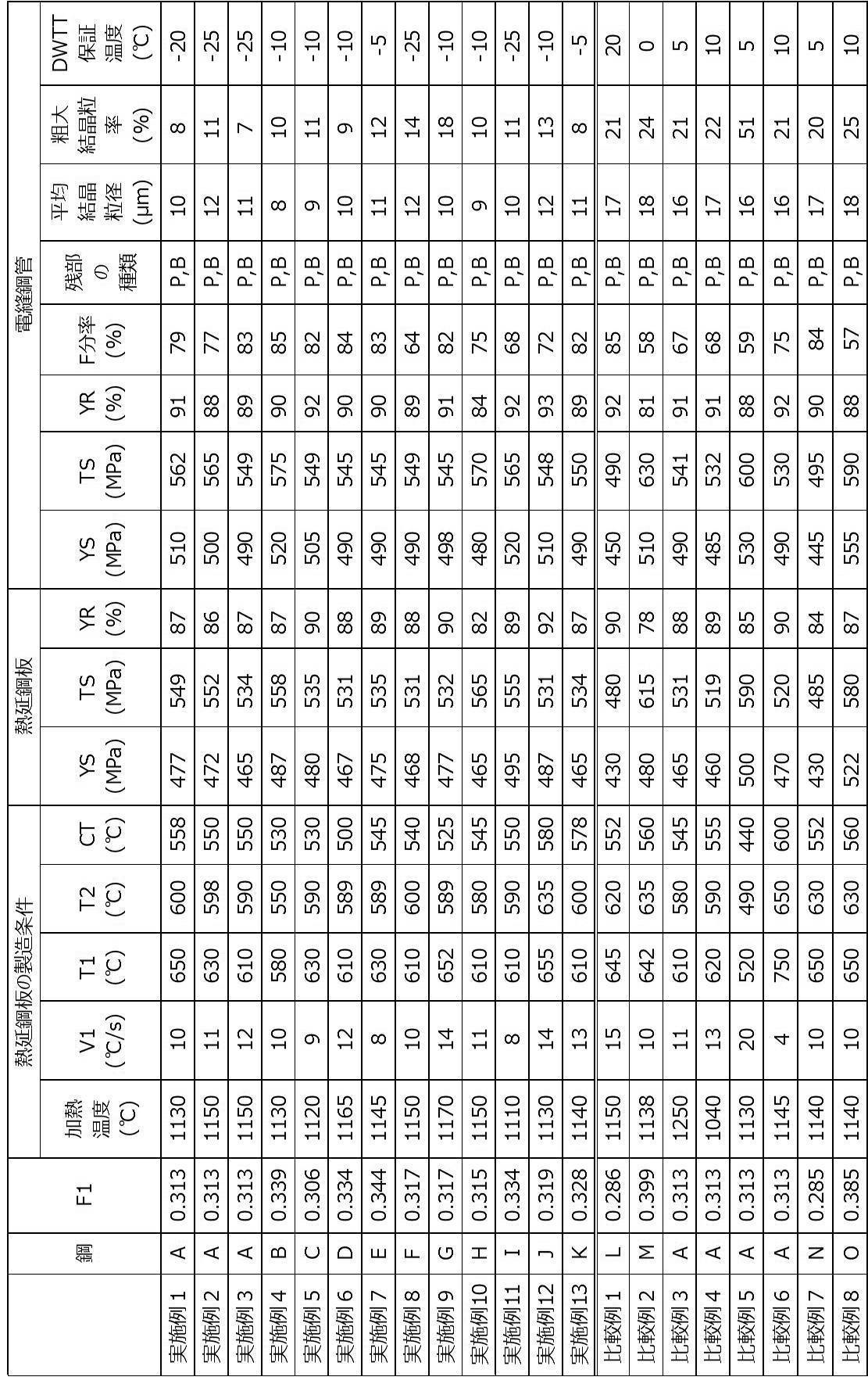
表1及び表2に示すように、本開示における母材部の化学組成(F1が0.300~0.350であることを含む)を満足し、母材部の肉厚中央部の金属組織において、F分率が60~90%であり、平均結晶粒径が15μm以下であり、粗大結晶粒率が20%以下である各実施例の電縫鋼管は、DWTT保証温度が低く、低温靭性に優れていた。
また、各実施例の電縫鋼管は、YRが80~95%の範囲内であり、ラインパイプ用鋼管として要求される塑性変形代が確保されていることが確認された。
また、各実施例の電縫鋼管は、YRが80~95%の範囲内であり、ラインパイプ用鋼管として要求される塑性変形代が確保されていることが確認された。
各実施例に対し、F1が0.300未満である比較例1及び7では、平均結晶粒径が過大であり、DWTT保証温度が高すぎた(即ち、低温靭性に劣っていた)。平均結晶粒径が過大であった理由は、F1が0.300未満であることにより、フェライト粒が粗大化したためと考えられる。
また、F1が0.350超である比較例2及び8では、F分率が低すぎ、DWTT保証温度が高すぎた(即ち、低温靭性に劣っていた)。
これら比較例2及び8では、平均結晶粒径及び粗大結晶粒率が過大であった。この理由は、F1が0.350超であることにより、F分率が低くなりすぎたためと考えられる。
これら比較例2及び8では、平均結晶粒径及び粗大結晶粒率が過大であった。この理由は、F1が0.350超であることにより、F分率が低くなりすぎたためと考えられる。
また、比較例3では、平均結晶粒径及び粗大結晶粒率が過大であり、DWTT保証温度が高すぎた(即ち、低温靭性に劣っていた)。
比較例3において平均結晶粒径及び粗大結晶粒率が過大であった理由は、スラブの加熱温度が高すぎたために、スラブの加熱時にオーステナイト粒が粗大化したためと考えられる。
比較例3において平均結晶粒径及び粗大結晶粒率が過大であった理由は、スラブの加熱温度が高すぎたために、スラブの加熱時にオーステナイト粒が粗大化したためと考えられる。
また、比較例4では、平均結晶粒径及び粗大結晶粒率が過大であり、DWTT保証温度が高すぎた(即ち、低温靭性に劣っていた)。
比較例4において平均結晶粒径及び粗大結晶粒率が過大であった理由は、スラブの加熱温度が低すぎたために、圧延による結晶粒の微細化の効果が不十分であったためと考えられる。
比較例4において平均結晶粒径及び粗大結晶粒率が過大であった理由は、スラブの加熱温度が低すぎたために、圧延による結晶粒の微細化の効果が不十分であったためと考えられる。
また、比較例5では、F分率が低すぎ、DWTT保証温度が高かすぎた(即ち、低温靭性に劣っていた)。
比較例5においてF分率が低すぎた理由は、強冷却停止温度T1、徐冷却停止温度T2、及び巻取り温度CTが低すぎたためと考えられる。
比較例5においてF分率が低すぎた理由は、強冷却停止温度T1、徐冷却停止温度T2、及び巻取り温度CTが低すぎたためと考えられる。
また、比較例6では、平均結晶粒径及び粗大結晶粒率が過大であり、DWTT保証温度が高かすぎた(即ち、低温靭性に劣っていた)。
比較例6において平均結晶粒径及び粗大結晶粒率が過大であった理由は、強冷却における冷却速度V1が低すぎたために、強冷却停止温度T1及び巻取り温度CTが高くなりすぎ、その結果、粗大なフェライト粒が生じたためと考えられる。
比較例6において平均結晶粒径及び粗大結晶粒率が過大であった理由は、強冷却における冷却速度V1が低すぎたために、強冷却停止温度T1及び巻取り温度CTが高くなりすぎ、その結果、粗大なフェライト粒が生じたためと考えられる。
Claims (7)
- 母材部及び電縫溶接部を含み、
前記母材部の化学組成が、質量%で、
C: 0.030~0.120%、
Si:0.05~0.30%、
Mn:0.50~2.00%、
P :0~0.030%、
S :0~0.0100%、
Al:0.010~0.035%、
N :0.0010~0.0080%、
Nb:0.010~0.080%、
Ti:0.005~0.030%、
Ni:0.001~0.20%、
Mo:0.10~0.20%、
V:0~0.010%、
O:0~0.0030%、
Ca:0~0.0050%、
Cr:0~0.30%、
Cu:0~0.30%、
Mg:0~0.0050%、
REM:0~0.0100%、及び
残部:Fe及び不純物からなり、下記式(1)で定義されるF1が0.300~0.350であり、
前記母材部の肉厚中央部の金属組織において、ポリゴナルフェライト分率が60~90%であり、平均結晶粒径が15μm以下であり、結晶粒径が20μm以上の結晶粒の面積率である粗大結晶粒率が20%以下であり、
管軸方向の降伏比が80~95%であるラインパイプ用アズロール電縫鋼管。
F1 = C+Si/24+Mn/6+Ni/40+Cr/5+Mo/4+V/3+Nb/3 … 式(1)
〔式(1)において、C、Si、Mn、Ni、Cr、Mo、V、及びNbは、それぞれ、各元素の質量%を表す。〕 - 前記母材部の化学組成が、質量%で、
V:0%超0.010%以下、
Ca:0%超0.0030%以下、
Cr:0%超0.30%以下、
Cu:0%超0.30%以下、
Mg:0%超0.0050%以下、及び
REM:0%超0.0100%以下からなる群から選択される1種以上を含有する請求項1に記載のラインパイプ用アズロール電縫鋼管。 - 管軸方向の降伏強度が450~540MPaであり、管軸方向の引張強度が510~625MPaである請求項1又は請求項2に記載のラインパイプ用アズロール電縫鋼管。
- 肉厚が12~25mmであり、外径が304.8~660.4mmである請求項1~請求項3のいずれか1項に記載のラインパイプ用アズロール電縫鋼管。
- 前記管軸方向の降伏比が80~93%である請求項1~請求項4のいずれか1項に記載のラインパイプ用アズロール電縫鋼管。
- 請求項1~請求項5のいずれか1項に記載のラインパイプ用アズロール電縫鋼管の製造に用いられる熱延鋼板であって、
化学組成が、質量%で、
C: 0.030~0.120%、
Si:0.05~0.30%、
Mn:0.50~2.00%、
P :0~0.030%、
S :0~0.0100%、
Al:0.010~0.035%、
N :0.0010~0.0080%、
Nb:0.010~0.080%、
Ti:0.005~0.030%、
Ni:0.001~0.20%、
Mo:0.10~0.20%、
V:0~0.010%、
O:0~0.0030%、
Ca:0~0.0050%、
Cr:0~0.30%、
Cu:0~0.30%、
Mg:0~0.0050%、
REM:0~0.0100%、及び
残部:Fe及び不純物からなり、前記式(1)で定義されるF1が0.300~0.350であり、
肉厚中央部の金属組織において、ポリゴナルフェライト分率が60~90%であり、平均結晶粒径が15μm以下であり、結晶粒径が20μm以上の結晶粒の面積率である粗大結晶粒率が20%以下である熱延鋼板。 - 圧延方向の降伏強度が450~500MPaであり、圧延方向の引張強度が510~580MPaである請求項6に記載の熱延鋼板。
Priority Applications (4)
| Application Number | Priority Date | Filing Date | Title |
|---|---|---|---|
| JP2017552185A JP6260757B1 (ja) | 2017-06-22 | 2017-06-22 | ラインパイプ用アズロール電縫鋼管及び熱延鋼板 |
| EP17914739.2A EP3608434B1 (en) | 2017-06-22 | 2017-06-22 | As-rolled electric resistance-welded steel pipe for line pipe, and hot-rolled steel sheet |
| PCT/JP2017/023086 WO2018235244A1 (ja) | 2017-06-22 | 2017-06-22 | ラインパイプ用アズロール電縫鋼管及び熱延鋼板 |
| CN201780089464.6A CN110546289A (zh) | 2017-06-22 | 2017-06-22 | 管线管用轧态电阻焊钢管及热轧钢板 |
Applications Claiming Priority (1)
| Application Number | Priority Date | Filing Date | Title |
|---|---|---|---|
| PCT/JP2017/023086 WO2018235244A1 (ja) | 2017-06-22 | 2017-06-22 | ラインパイプ用アズロール電縫鋼管及び熱延鋼板 |
Publications (1)
| Publication Number | Publication Date |
|---|---|
| WO2018235244A1 true WO2018235244A1 (ja) | 2018-12-27 |
Family
ID=60989198
Family Applications (1)
| Application Number | Title | Priority Date | Filing Date |
|---|---|---|---|
| PCT/JP2017/023086 WO2018235244A1 (ja) | 2017-06-22 | 2017-06-22 | ラインパイプ用アズロール電縫鋼管及び熱延鋼板 |
Country Status (4)
| Country | Link |
|---|---|
| EP (1) | EP3608434B1 (ja) |
| JP (1) | JP6260757B1 (ja) |
| CN (1) | CN110546289A (ja) |
| WO (1) | WO2018235244A1 (ja) |
Cited By (9)
| Publication number | Priority date | Publication date | Assignee | Title |
|---|---|---|---|---|
| JP2020066747A (ja) * | 2018-10-22 | 2020-04-30 | 日本製鉄株式会社 | ラインパイプ用電縫鋼管、及び、ラインパイプ用熱延鋼板 |
| JP2020066746A (ja) * | 2018-10-22 | 2020-04-30 | 日本製鉄株式会社 | ラインパイプ用鋼材 |
| JP2020066745A (ja) * | 2018-10-22 | 2020-04-30 | 日本製鉄株式会社 | ラインパイプ用鋼材 |
| JP6693610B1 (ja) * | 2019-08-23 | 2020-05-13 | 日本製鉄株式会社 | ラインパイプ用電縫鋼管 |
| JP2021042424A (ja) * | 2019-09-10 | 2021-03-18 | 日本製鉄株式会社 | ラインパイプ用電縫鋼管、及び、ラインパイプ用熱延鋼板 |
| WO2021085036A1 (ja) * | 2019-10-31 | 2021-05-06 | Jfeスチール株式会社 | 電縫鋼管およびその製造方法ならびにラインパイプおよび建築構造物 |
| EP4029962A4 (en) * | 2019-11-20 | 2022-09-21 | JFE Steel Corporation | HOT ROLLED STEEL SHEET FOR ELECTRO-WELDED STEEL PIPE AND PRODUCTION METHOD THEREOF, ELECTRO-WELDED STEEL PIPE AND PRODUCTION METHOD THEREOF, PIPELINE AND BUILDING STRUCTURE |
| WO2023053837A1 (ja) * | 2021-09-29 | 2023-04-06 | Jfeスチール株式会社 | 角形鋼管およびその製造方法、熱延鋼板およびその製造方法、並びに建築構造物 |
| EP4066954A4 (en) * | 2020-02-10 | 2023-07-05 | Nippon Steel Corporation | ELECTRICAL RESISTANCE WELDED STEEL PIPE FOR LINE PIPE USE |
Families Citing this family (3)
| Publication number | Priority date | Publication date | Assignee | Title |
|---|---|---|---|---|
| KR102236852B1 (ko) * | 2018-11-30 | 2021-04-06 | 주식회사 포스코 | 우수한 저항복비 및 저온인성 특성을 가지는 구조용강 및 그 제조방법 |
| WO2021200402A1 (ja) * | 2020-04-02 | 2021-10-07 | Jfeスチール株式会社 | 電縫鋼管およびその製造方法 |
| US20240026999A1 (en) | 2020-10-05 | 2024-01-25 | Jfe Steel Corporation | Electric resistance welded steel pipe and method for manufacturing the same |
Citations (5)
| Publication number | Priority date | Publication date | Assignee | Title |
|---|---|---|---|---|
| JPH10298645A (ja) * | 1997-04-24 | 1998-11-10 | Sumitomo Metal Ind Ltd | 熱延高張力鋼板の製造方法 |
| WO2012002481A1 (ja) | 2010-06-30 | 2012-01-05 | 新日本製鐵株式会社 | 熱延鋼板及びその製造方法 |
| WO2013027779A1 (ja) * | 2011-08-23 | 2013-02-28 | 新日鐵住金株式会社 | 厚肉電縫鋼管及びその製造方法 |
| WO2014051119A1 (ja) * | 2012-09-27 | 2014-04-03 | 新日鐵住金株式会社 | 電縫溶接鋼管 |
| JP2016033236A (ja) * | 2014-07-31 | 2016-03-10 | Jfeスチール株式会社 | 強度−均一伸びバランスに優れた高強度熱延鋼板およびその製造方法 |
Family Cites Families (6)
| Publication number | Priority date | Publication date | Assignee | Title |
|---|---|---|---|---|
| JP4788146B2 (ja) * | 2004-03-09 | 2011-10-05 | Jfeスチール株式会社 | 耐時効性に優れた低yr型電縫溶接鋼管用熱延鋼板とその製造方法 |
| JP4853075B2 (ja) * | 2006-03-28 | 2012-01-11 | 住友金属工業株式会社 | ハイドロフォーム加工用熱延鋼板及びその製造法と、ハイドロフォーム加工用電縫鋼管 |
| JP5292784B2 (ja) * | 2006-11-30 | 2013-09-18 | 新日鐵住金株式会社 | 低温靱性に優れた高強度ラインパイプ用溶接鋼管及びその製造方法 |
| JP5000447B2 (ja) * | 2007-02-13 | 2012-08-15 | 新日本製鐵株式会社 | 高強度電縫ラインパイプ |
| KR101641450B1 (ko) * | 2012-04-13 | 2016-07-20 | 제이에프이 스틸 가부시키가이샤 | 우수한 저온 인성을 갖는 고강도 후육 전봉 강관 및 그 제조 방법 |
| JP6288390B1 (ja) * | 2017-03-29 | 2018-03-07 | 新日鐵住金株式会社 | ラインパイプ用アズロール電縫鋼管 |
-
2017
- 2017-06-22 JP JP2017552185A patent/JP6260757B1/ja active Active
- 2017-06-22 EP EP17914739.2A patent/EP3608434B1/en active Active
- 2017-06-22 WO PCT/JP2017/023086 patent/WO2018235244A1/ja unknown
- 2017-06-22 CN CN201780089464.6A patent/CN110546289A/zh active Pending
Patent Citations (5)
| Publication number | Priority date | Publication date | Assignee | Title |
|---|---|---|---|---|
| JPH10298645A (ja) * | 1997-04-24 | 1998-11-10 | Sumitomo Metal Ind Ltd | 熱延高張力鋼板の製造方法 |
| WO2012002481A1 (ja) | 2010-06-30 | 2012-01-05 | 新日本製鐵株式会社 | 熱延鋼板及びその製造方法 |
| WO2013027779A1 (ja) * | 2011-08-23 | 2013-02-28 | 新日鐵住金株式会社 | 厚肉電縫鋼管及びその製造方法 |
| WO2014051119A1 (ja) * | 2012-09-27 | 2014-04-03 | 新日鐵住金株式会社 | 電縫溶接鋼管 |
| JP2016033236A (ja) * | 2014-07-31 | 2016-03-10 | Jfeスチール株式会社 | 強度−均一伸びバランスに優れた高強度熱延鋼板およびその製造方法 |
Non-Patent Citations (1)
| Title |
|---|
| See also references of EP3608434A4 * |
Cited By (18)
| Publication number | Priority date | Publication date | Assignee | Title |
|---|---|---|---|---|
| JP7159785B2 (ja) | 2018-10-22 | 2022-10-25 | 日本製鉄株式会社 | ラインパイプ用鋼材 |
| JP2020066746A (ja) * | 2018-10-22 | 2020-04-30 | 日本製鉄株式会社 | ラインパイプ用鋼材 |
| JP2020066745A (ja) * | 2018-10-22 | 2020-04-30 | 日本製鉄株式会社 | ラインパイプ用鋼材 |
| JP7206792B2 (ja) | 2018-10-22 | 2023-01-18 | 日本製鉄株式会社 | ラインパイプ用鋼材 |
| JP2020066747A (ja) * | 2018-10-22 | 2020-04-30 | 日本製鉄株式会社 | ラインパイプ用電縫鋼管、及び、ラインパイプ用熱延鋼板 |
| JP7206793B2 (ja) | 2018-10-22 | 2023-01-18 | 日本製鉄株式会社 | ラインパイプ用電縫鋼管、及び、ラインパイプ用熱延鋼板 |
| WO2021038632A1 (ja) * | 2019-08-23 | 2021-03-04 | 日本製鉄株式会社 | ラインパイプ用電縫鋼管 |
| EP3960891A4 (en) * | 2019-08-23 | 2022-07-27 | Nippon Steel Corporation | ELECTRICAL RESISTANCE WELDED STEEL PIPE FOR PIPELINES |
| JP6693610B1 (ja) * | 2019-08-23 | 2020-05-13 | 日本製鉄株式会社 | ラインパイプ用電縫鋼管 |
| JP2021042424A (ja) * | 2019-09-10 | 2021-03-18 | 日本製鉄株式会社 | ラインパイプ用電縫鋼管、及び、ラインパイプ用熱延鋼板 |
| JP7315834B2 (ja) | 2019-09-10 | 2023-07-27 | 日本製鉄株式会社 | ラインパイプ用電縫鋼管、及び、ラインパイプ用熱延鋼板 |
| JPWO2021085036A1 (ja) * | 2019-10-31 | 2021-05-06 | ||
| JP6947333B2 (ja) * | 2019-10-31 | 2021-10-13 | Jfeスチール株式会社 | 電縫鋼管およびその製造方法ならびにラインパイプおよび建築構造物 |
| TWI748684B (zh) * | 2019-10-31 | 2021-12-01 | 日商Jfe鋼鐵股份有限公司 | 電焊鋼管及其製造方法、輸送管以及建築構造物 |
| WO2021085036A1 (ja) * | 2019-10-31 | 2021-05-06 | Jfeスチール株式会社 | 電縫鋼管およびその製造方法ならびにラインパイプおよび建築構造物 |
| EP4029962A4 (en) * | 2019-11-20 | 2022-09-21 | JFE Steel Corporation | HOT ROLLED STEEL SHEET FOR ELECTRO-WELDED STEEL PIPE AND PRODUCTION METHOD THEREOF, ELECTRO-WELDED STEEL PIPE AND PRODUCTION METHOD THEREOF, PIPELINE AND BUILDING STRUCTURE |
| EP4066954A4 (en) * | 2020-02-10 | 2023-07-05 | Nippon Steel Corporation | ELECTRICAL RESISTANCE WELDED STEEL PIPE FOR LINE PIPE USE |
| WO2023053837A1 (ja) * | 2021-09-29 | 2023-04-06 | Jfeスチール株式会社 | 角形鋼管およびその製造方法、熱延鋼板およびその製造方法、並びに建築構造物 |
Also Published As
| Publication number | Publication date |
|---|---|
| EP3608434A1 (en) | 2020-02-12 |
| CN110546289A (zh) | 2019-12-06 |
| EP3608434B1 (en) | 2021-06-02 |
| JPWO2018235244A1 (ja) | 2019-06-27 |
| JP6260757B1 (ja) | 2018-01-17 |
| EP3608434A4 (en) | 2020-09-02 |
Similar Documents
| Publication | Publication Date | Title |
|---|---|---|
| JP6260757B1 (ja) | ラインパイプ用アズロール電縫鋼管及び熱延鋼板 | |
| JP6288390B1 (ja) | ラインパイプ用アズロール電縫鋼管 | |
| WO2014162680A1 (ja) | 熱延鋼板およびその製造方法 | |
| JP6354910B2 (ja) | 厚肉高強度ラインパイプ用熱延鋼板、ならびに、厚肉高強度ラインパイプ用溶接鋼管およびその製造方法 | |
| WO2013047702A1 (ja) | ラインパイプ用ホットコイル及びその製造方法 | |
| US20060151074A1 (en) | Steel plate and welded steel tube exhibiting low yield ratio, high strength and high toughness and method for producing thereof | |
| US20190062862A1 (en) | High-strength hot-rolled steel sheet for electric resistance welded steel pipe and manufacturing method therefor | |
| JP6587041B1 (ja) | ラインパイプ用電縫鋼管 | |
| WO2013089156A1 (ja) | 低温靭性に優れた高強度h形鋼及びその製造方法 | |
| WO2015092916A1 (ja) | 電縫溶接鋼管 | |
| JP5742123B2 (ja) | ラインパイプ用高強度溶接鋼管向け高張力熱延鋼板およびその製造方法 | |
| JPWO2019220577A1 (ja) | トーションビーム用アズロール電縫鋼管 | |
| JP2018104757A (ja) | ラインパイプ用鋼材及びその製造方法 | |
| US11028456B2 (en) | Electric resistance welded steel pipe for torsion beam | |
| JP2020066747A (ja) | ラインパイプ用電縫鋼管、及び、ラインパイプ用熱延鋼板 | |
| JP7159785B2 (ja) | ラインパイプ用鋼材 | |
| JP2018178210A (ja) | ラインパイプ用電縫鋼管及びその製造方法 | |
| JP7315834B2 (ja) | ラインパイプ用電縫鋼管、及び、ラインパイプ用熱延鋼板 | |
| JP7323797B2 (ja) | ラインパイプ用電縫鋼管、及び、ラインパイプ用熱延鋼板 | |
| US11739866B2 (en) | Electric resistance welded steel pipe for torsion beam | |
| JP6693610B1 (ja) | ラインパイプ用電縫鋼管 | |
| JP6123734B2 (ja) | 鋼管杭向け低降伏比高強度電縫鋼管およびその製造方法 | |
| JP7448804B2 (ja) | ラインパイプ用電縫鋼管、及びラインパイプ用熱延鋼板 | |
| JP7206792B2 (ja) | ラインパイプ用鋼材 | |
| JP7315835B2 (ja) | ラインパイプ用電縫鋼管、及び、ラインパイプ用熱延鋼板 |
Legal Events
| Date | Code | Title | Description |
|---|---|---|---|
| ENP | Entry into the national phase |
Ref document number: 2017552185 Country of ref document: JP Kind code of ref document: A |
|
| 121 | Ep: the epo has been informed by wipo that ep was designated in this application |
Ref document number: 17914739 Country of ref document: EP Kind code of ref document: A1 |
|
| ENP | Entry into the national phase |
Ref document number: 2017914739 Country of ref document: EP Effective date: 20191107 |
|
| NENP | Non-entry into the national phase |
Ref country code: DE |