WO2018230697A1 - 光照射装置、光照射方法 - Google Patents
光照射装置、光照射方法 Download PDFInfo
- Publication number
- WO2018230697A1 WO2018230697A1 PCT/JP2018/022873 JP2018022873W WO2018230697A1 WO 2018230697 A1 WO2018230697 A1 WO 2018230697A1 JP 2018022873 W JP2018022873 W JP 2018022873W WO 2018230697 A1 WO2018230697 A1 WO 2018230697A1
- Authority
- WO
- WIPO (PCT)
- Prior art keywords
- light
- reflector
- light source
- optical fiber
- focal point
- Prior art date
Links
Images


Classifications
-
- B—PERFORMING OPERATIONS; TRANSPORTING
- B05—SPRAYING OR ATOMISING IN GENERAL; APPLYING FLUENT MATERIALS TO SURFACES, IN GENERAL
- B05C—APPARATUS FOR APPLYING FLUENT MATERIALS TO SURFACES, IN GENERAL
- B05C9/00—Apparatus or plant for applying liquid or other fluent material to surfaces by means not covered by any preceding group, or in which the means of applying the liquid or other fluent material is not important
- B05C9/08—Apparatus or plant for applying liquid or other fluent material to surfaces by means not covered by any preceding group, or in which the means of applying the liquid or other fluent material is not important for applying liquid or other fluent material and performing an auxiliary operation
- B05C9/12—Apparatus or plant for applying liquid or other fluent material to surfaces by means not covered by any preceding group, or in which the means of applying the liquid or other fluent material is not important for applying liquid or other fluent material and performing an auxiliary operation the auxiliary operation being performed after the application
-
- C—CHEMISTRY; METALLURGY
- C03—GLASS; MINERAL OR SLAG WOOL
- C03C—CHEMICAL COMPOSITION OF GLASSES, GLAZES OR VITREOUS ENAMELS; SURFACE TREATMENT OF GLASS; SURFACE TREATMENT OF FIBRES OR FILAMENTS MADE FROM GLASS, MINERALS OR SLAGS; JOINING GLASS TO GLASS OR OTHER MATERIALS
- C03C25/00—Surface treatment of fibres or filaments made from glass, minerals or slags
- C03C25/62—Surface treatment of fibres or filaments made from glass, minerals or slags by application of electric or wave energy; by particle radiation or ion implantation
- C03C25/6206—Electromagnetic waves
- C03C25/6226—Ultraviolet
-
- G—PHYSICS
- G02—OPTICS
- G02B—OPTICAL ELEMENTS, SYSTEMS OR APPARATUS
- G02B6/00—Light guides; Structural details of arrangements comprising light guides and other optical elements, e.g. couplings
- G02B6/44—Mechanical structures for providing tensile strength and external protection for fibres, e.g. optical transmission cables
Definitions
- the present invention relates to a light irradiation apparatus and a light irradiation method for irradiating light toward a wire.
- An optical fiber is manufactured by coating a resin on the surface of a bare optical fiber drawn from a preform or an optical fiber strand once wound on a bobbin. At this time, after the outer periphery of the optical fiber (wire) is coated with an ultraviolet curable resin, a step of curing the resin is performed by irradiating the resin with ultraviolet light. More specifically, ultraviolet light is irradiated from a light source to a wire that moves at a predetermined speed.
- Patent Document 1 discloses a configuration in which a light source is arranged so as to surround a wire for the purpose of efficiently irradiating light in the circumferential direction of the wire.
- Patent Document 2 discloses a configuration in which an elliptical reflector is used, a light source is disposed at one focal point, and an optical fiber as an irradiation target is disposed at the other focal point.
- JP 2010-117531 A US Patent Application Publication No. 2016/0038970
- Patent Document 1 since it is necessary to arrange a light source so as to surround the wire, there is a problem that the device configuration becomes complicated.
- An object of the present invention is to provide a light irradiation apparatus and a light irradiation method capable of irradiating light to a wire with high efficiency under a simple configuration.
- the light irradiation device includes: An insertion path for inserting a wire, A reflector having an elliptical arc shape with a first focal point decentered by a first distance from the center of the insertion path, and a reflector having a surface facing the insertion path as a reflection surface; A light source that is disposed at a position opposite to the reflector with respect to the insertion path, and that emits light toward the wire; The insertion path is arranged at a position eccentric by the first distance on the light source side with respect to the first focal point.
- the center position of the insertion path (that is, the center position of the wire) is arranged so as to be eccentric to the light source side with respect to the first focal point of the reflector having the elliptical arc-shaped reflection surface It was confirmed that the amount of light applied to the wire increased compared to the case where the first focal point of the reflector was aligned with the center of the wire. This verification result will be described later in the section “DETAILED DESCRIPTION OF THE INVENTION”.
- the light source may be arranged at a position decentered by a second distance from the second focal point of the reflector having an elliptical arc shape to the first focal point side.
- the light source may be composed of a plurality of LED elements.
- the light irradiation device is made of a material having transparency to light emitted from the light source, and includes an insertion portion that forms the insertion path therein.
- the outer periphery of the insertion part may be located on the side closer to the center of the elliptical arc of the reflector with respect to the reflecting surface of the reflector.
- the reflecting surface of the reflector may be formed as a curved surface, or may be formed by arranging a plurality of planes in an elliptical arc shape.
- the present invention is a light irradiation method in which the light irradiation device irradiates light toward the wire,
- the light irradiation device is: A reflector having an elliptical arc shape and a surface facing inward as a reflecting surface;
- a light source for irradiating light toward the wire The light irradiation method includes: Inserting the wire into a region inside the reflective surface of the reflector so that a center position of the wire is decentered by a first distance from the first focal point of the reflective surface of the reflector toward the light source side.
- the light source may be arranged at a position decentered by a second distance from the second focal point of the reflector having an elliptic arc shape toward the first focal point.
- the light irradiation apparatus of the present invention it is possible to irradiate light to the wire with high efficiency under a simple configuration.
- FIG. 3 is a cross-sectional view taken along line A1-A1 in FIG. It is an enlarged view in area
- FIG. It is drawing which shows typically the structure of the light irradiation apparatus of the comparative example 1 and Example 1.
- FIG. It is a figure which shows typically the reverse ray tracing figure in the light irradiation apparatus of the comparative example 1 and Example 1.
- FIG. 1 is a drawing schematically showing the structure of an optical fiber manufacturing apparatus including a light irradiation device. As shown in FIG. 1, the light irradiation apparatus 1 is used as a part of an optical fiber manufacturing apparatus 100 that manufactures an optical fiber. Below, before demonstrating the structure of the light irradiation apparatus 1, the optical fiber manufacturing apparatus 100 is demonstrated.
- the optical fiber manufacturing apparatus 100 includes a transport device 110 that transports the optical fiber 200 and a coating device 120 that coats the transported optical fiber 200 with an ultraviolet curable resin.
- the optical fiber 200 is constituted by, for example, a bare optical fiber made of glass fiber, and an ultraviolet curable resin is applied to the outer periphery of the bare optical fiber by passing through the coating device 120.
- the transport device 110 irradiates the transport members 111 and 112 transporting in the direction D1 in FIG. 1 while holding the optical fiber 200 so that the optical fiber 200 is inserted into a predetermined position inside the light irradiation device 1.
- the apparatus 1 is provided on the upstream side and the downstream side, respectively.
- the optical fiber 200 corresponds to a “wire”.
- the light irradiation device 1 irradiates the optical fiber 200 conveyed in the D1 direction at a speed of 1000 meters per minute with ultraviolet rays, for example. Thereby, the resin applied to the outer periphery of the optical fiber 200 is cured. As a result, the optical fiber 200 that has passed through the light irradiation device 1 has a configuration in which a coating film in which an ultraviolet curable resin is cured is covered on the outer periphery of the bare optical fiber.
- FIG. 2 is an overall front view schematically showing the structure of the light irradiation device 1.
- FIG. 3 is an overall side view schematically showing the structure of the light irradiation device 1.
- 4 is a cross-sectional view taken along line A1-A1 in FIG.
- FIG. 5 is an enlarged view of a region A2 in FIG.
- the light irradiation device 1 includes a light source unit 2 that irradiates light toward the optical fiber 200, and an insertion unit 3 into which the optical fiber 200 is inserted.
- the light irradiation device 1 includes a connection portion 4 that connects the light source unit 2 and the insertion unit 3 so as to be rotatable by a rotation shaft 4a.
- the light source unit 2 includes a light source 21 that emits light toward the optical fiber 200, a light source cooling unit 22 that cools the light source 21, and a housing 23 that houses the light source 21 and the like.
- the light source unit 2 includes a power supply unit 24 for supplying power to the light source 21.
- the light source 21 is formed to be long along the transport direction D1 of the optical fiber 200 and is disposed so as to face the optical fiber 200.
- the light source 21 is composed of a substrate on which a plurality of LED elements are mounted.
- the light source 21 emits ultraviolet light (for example, light having a wavelength of 300 nm to 400 nm) in order to cure the ultraviolet curable resin.
- the light source cooling unit 22 is connected to the light source 21, and includes a cooling main body 22a through which a refrigerant (for example, cooling water) flows, an inflow portion 22b for flowing the refrigerant into the cooling main body 22a, and a refrigerant from the cooling main body 22a. And an outflow part 22c for outflowing.
- the cooling body 22 a is disposed inside the housing 23, and the inflow portion 22 b and the outflow portion 22 c are disposed outside the housing 23.
- the housing 23 includes a light-transmitting portion 23a that transmits light emitted from the light source 21 and a light-shielding portion 23b that blocks light.
- the translucent part 23 a is formed in a long shape along the transport direction D ⁇ b> 1 of the optical fiber 200 and is disposed so as to face the light source 21. That is, the translucent part 23 a is disposed between the light source 21 and the optical fiber 200.
- the power supply unit 24 is connected to a power supply connection unit 24a to which a cable or the like is connected, and various types of electrical connection between the power supply connection unit 24a and the light source 21 are performed.
- a terminal block 24b having terminals.
- the power connection part 24 a is disposed outside the housing 23, and the terminal block 24 b is disposed inside the housing 23.
- the fixing part 7 includes a pair of clamping parts 71 and 72 that clamp the insertion part 6.
- the fixing portion 7 is configured such that the pair of sandwiching portions 71 and 72 sandwich the end portion in the longitudinal direction (D1 direction) of the insertion portion 6, whereby the longitudinal end portion of the insertion portion 6 and the longitudinal end portion of the main body portion 5 are arranged. The part is fixed.
- the insertion unit 3 includes a main body portion 5 into which the optical fiber 200 is inserted, and an insertion portion 6 that internally forms an insertion path 61 (see FIG. 5) for inserting the optical fiber 200 into the main body portion 5. And a fixing portion 7 for fixing the insertion portion 6 to the main body portion 5.
- the insertion unit 3 includes a main body cooling unit 8 that cools the main body unit 5.
- the main body cooling unit 8 is connected to the main body unit 5, and includes a cooling main body 8a through which a refrigerant (for example, cooling water) flows, an inflow portion 8b for flowing cooling water into the cooling main body 8a, and a cooling main body 8a. And an outflow portion 8c for allowing cooling water to flow out from the main body.
- the main body cooling unit 8 (cooling main body 8 a) is configured to be detachable from the main body unit 5.
- the main body 5 is formed in an elongated shape along the transport direction D ⁇ b> 1 of the optical fiber 200, and the concave portion into which the optical fiber 200 is inserted along the longitudinal direction. 50.
- the inner surface of the concave portion 50 includes a reflector 51 having a reflective surface 51c.
- the concave portion 50 includes an opening 53 on one side in the circumferential direction of the reflector 51.
- the reflector 51 is formed long along the transport direction D1 of the optical fiber 200.
- the reflecting surface 51c of the reflector 51 is formed with a curved surface.
- the reflecting surface 51c of the reflector 51 is formed in an elliptical arc shape composed of a part of an ellipse in a cross section taken along a plane orthogonal to the longitudinal direction (D2-D3 plane).
- the opening 53 is formed long along the transport direction D1 of the optical fiber 200.
- the opening 53 is covered with the light transmitting portion 23 a and is disposed so as to face the light source 21.
- the insertion portion 6 is formed of a cylindrical body that forms an insertion path 61 therein, and is formed of a member that has translucency with respect to light emitted from the light source 21.
- the insertion path 61 has a circular shape when viewed along the transport direction D1 of the optical fiber 200, that is, on the D2-D3 plane.
- the light emitted from the light source 21 is applied to the outer peripheral surface of the optical fiber 200 that is inserted into the insertion path 61 via the translucent part 23 a, the opening 53, and the insertion part 6. A part of the light is reflected once or a plurality of times by the reflecting surface 51 c of the reflector 51, and then irradiated on the outer peripheral surface of the optical fiber 200 inserted into the insertion path 61.
- the insertion portion 6 is made of a quartz tube as an example, and the inside thereof is filled with nitrogen. Since the volatile matter is generated when the resin on the outer surface of the optical fiber 200 is cured, the above configuration prevents the volatile matter from adhering to the light source unit 2 (translucent portion 23a) and the reflecting surface 51c.
- the reflector 51 is arranged so that the first focal point 51a of the reflecting surface 51c showing an elliptical arc shape is decentered from the center 61a of the insertion path 61 by a first distance d1. Further, in the present embodiment, the reflector 51 is arranged so that the second focal point 51b of the reflecting surface 51c showing an elliptical arc shape is eccentric from the position of the light emitting surface 21a of the light source 21 by the second distance d2. Yes.
- the second distance d2 is different from the first distance d1, but may be the same.
- the first distance d1 may be referred to as an eccentric amount from the first focal point 51a
- the second distance d2 may be referred to as an eccentric amount from the second focal point 51b.
- the irradiation efficiency with respect to the optical fiber 200 is improved, and the first of the reflecting surfaces 51c of the reflector 51 is increased.
- the point that the irradiation efficiency with respect to the optical fiber 200 is further improved by decentering the two focal points 51b from the position of the light emitting surface 21a of the light source 21 will be described later.
- FIG. 6 is a drawing schematically showing the configuration of the light irradiation apparatus of Comparative Example 1 and Example 1.
- the reflector 51 having the elliptical arc-shaped reflection surface 51 c has the first focal point 51 a located at the center 200 a of the optical fiber 200 and the second focal point located at the light emitting surface 21 a of the light source 21. It arrange
- the center 200a of the optical fiber 200 is located at a position that is decentered from the first focal point 51a of the reflector 51 by the first distance d1.
- the position of the light source 21 is the same as that of the first comparative example, and is arranged so as to coincide with the position of the second focal point 51b of the reflector 51.
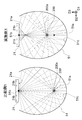
- FIG. 7 is a drawing schematically showing reverse ray tracing diagrams of Comparative Example 1 and Example 1. This drawing schematically shows the result of ray tracing of light emitted from a point light source when a virtual point light source is arranged at the position of the center 200a of the optical fiber 200 in each light irradiation device. Is. By tracing this drawing in reverse, a light beam that can irradiate the center 200a of the optical fiber 200 is determined. In FIG. 7, only light that is emitted from a virtual point light source and reaches the light source 21 after being reflected by the reflecting surface 51 c of the reflector 51 is illustrated.
- the optical fiber 200 is disposed at the position of the first focal point 51a, and the light emitting surface 21a of the light source 21 is disposed at the position of the second focal point 51b.
- the light emitted from the position of the second focal point 51b travels toward the optical fiber 200 after being reflected by the reflecting surface 51c.
- the light source 21 is composed of LED elements and emits light in a planar shape.
- the light emitting surface 21a has an area extending away from the second focal point 51b in the surface direction, that is, the end region 21b in the D2 direction, in addition to the region coinciding with the second focal point 51b.
- the light emitted from the end region 21 b and reflected by the reflecting surface 51 c of the reflector 51 does not reach the optical fiber 200 effectively.
- the optical fiber 200 when the optical fiber 200 is disposed at a position decentered from the first focal point 51a toward the light source 21 as in the first embodiment, the light emitted from the end region 21b of the light emitting surface 21a is reflected on the reflecting surface 51c. It is possible to proceed to the optical fiber 200 via That is, when the position of the optical fiber 200 is shifted from the first focal point 51a, a part of the light emitted from the position of the second focal point 51b on the light emitting surface 21a becomes difficult to reach the optical fiber 200, while on the light emitting surface 21a. The light emitted from the region (end region 21b) away from the second focal point 51b is irradiated on the optical fiber 200 after being reflected by the reflecting surface 51c.
- FIG. 8 is a graph showing the relationship between the amount of eccentricity of the optical fiber 200 from the first focal point 51a of the reflector 51 and the amount of light applied to the optical fiber 200.
- the horizontal axis indicates the value of the eccentricity d1 between the first focal point 51a of the reflector 51 and the center 200a of the optical fiber 200.
- the case where the amount of eccentricity is negative ( ⁇ ) means that the optical fiber 200 is eccentric in the direction approaching the light source 21, and the case where the amount of eccentricity is positive (+). This means that the optical fiber 200 is decentered in the direction away from the light source 21.
- the case where the amount of eccentricity is 0 means that the position of the optical fiber 200 coincides with the position of the first focal point 51a of the reflecting surface 51c of the reflector 51. This is the light irradiation of the first comparative example. Corresponds to the device.
- the position of the optical fiber 200 when the position of the optical fiber 200 is decentered from the first focus 51a toward the light source 21 (corresponding to the first embodiment), the position of the optical fiber 200 matches the position of the first focus 51a. It can be seen that the amount of irradiation light is improved as compared with the case. On the other hand, when the position of the optical fiber 200 is decentered from the first focus 51a to the side opposite to the light source 21, the amount of irradiation light is larger than when the position of the optical fiber 200 matches the position of the first focus 51a. It turns out that falls.
- the amount of the light beam that has been irradiated to the optical fiber 200 is larger than the light beam that is no longer irradiated to the optical fiber 200. It is thought that the amount of irradiation light has improved.
- the light emitted from the position of the second focal point 51b becomes difficult to reach the optical fiber 200 and the second focal point.
- the light emitted from the end region 21b away from 51b also reduces the amount of light flux that is applied to the optical fiber 200. This is because the optical fiber 200 as an irradiation target approaches the reflecting surface 51c of the reflector 51 and is at a position far from the light source 21, and as a result, the divergence angle for the light emitted from the light source 21 to reach the optical fiber 200. This is considered to be because the number of light beams reaching the optical fiber 200 is reduced.
- FIG. 9 is a graph showing the relationship between the amount of eccentricity of the light source 21 from the second focal point 51 b of the reflector 51 and the amount of light applied to the optical fiber 200.
- the horizontal axis indicates the value of the amount of eccentricity d ⁇ b> 2 between the second focal point 51 b of the reflector 51 and the light source 21.
- the vertical axis represents the relative value of the amount of light applied to the optical fiber 200, and corresponds to the ratio to the amount of light applied to the optical fiber 200 in the configuration of the first embodiment shown in FIG.
- the case where the amount of eccentricity is negative ( ⁇ ) means that the light source 21 is eccentric in the direction away from the first focal point 51a, and the case where the amount of eccentricity is positive (+). Means that the light source 21 is decentered in the direction of approaching the first focal point 51a. Moreover, the case where the amount of eccentricity is 0 means that the position of the light source 21 coincides with the position of the second focal point 51b of the reflecting surface 51c of the reflector 51. This is the light irradiation apparatus of the first embodiment.
- the amount of decrease in the amount of irradiation light by shifting the position of the light source 21 from the second focus 51 b to the side opposite to the first focus 51 a is the same as the position of the optical fiber 200.
- the amount of irradiation light is smaller than the amount of increase by shifting from the focal point 51a to the light source 21 side.
- the amount of light applied to the optical fiber 200 increases, and in addition, the position of the light source 21 is changed from the second focus 51b to the first focus 51a. It can be seen that the amount of light applied to the optical fiber 200 further increases by shifting to the side.
- the position of the light source 21 is shifted from the second focal point 51b to the opposite side of the first focal point 51a, the amount of light applied to the optical fiber 200 is reduced as compared with the configuration of the first embodiment, but the comparative example This is an improvement over the first configuration.
- the light source 21 is also arranged at a position decentered from the second focal point 51b, but the light source 21 may be arranged at the position of the second focal point 51b. .
- the first distance d1 between the center 51a of the reflecting surface 51c of the reflector 51 and the center 61a of the insertion path 61 is preferably not less than the radius of the optical fiber 200. More preferably, the diameter is equal to or larger than the diameter of the optical fiber 200. In this case, the center 51 a of the reflecting surface 51 c of the reflector 51 can be positioned outside the optical fiber 200.
- the reflecting surface 51c may be formed of an elliptical arc-shaped curved surface, or a substantially elliptical arc-shaped curved surface may be formed by combining a plurality of planes.
- the light source 21 is composed of a plurality of LED elements, but may be composed of a plurality of LD (laser diode) elements.
- the light irradiation device 1 may include a plurality of light sources 21.
- each light source 21 may be disposed at a position on the opposite side of the insertion path 61, that is, the optical fiber 200 with respect to the opening 53 (see FIG. 5) of the reflector 51.
- each light source 21 is arranged at a position opposite to the reflector 51 with respect to the insertion path 61, that is, the optical fiber 200.
- the insertion path 61 when viewed in the direction D1 is described as being circular, but the shape of the insertion path 61 is arbitrary.
- the insertion path 61 when viewed in the direction D1 may be, for example, a polygonal shape or an elliptical shape.
- the insertion path 61 is described as being configured by the inner portion of the insertion portion 6 made of a cylindrical body.
- the light irradiation device 1 does not include the insertion portion 6 itself, and the inner side of the reflector 51.
- the insertion path 61 may be configured by the partial space.
- the “center of the insertion path 61” means a passing position of the optical fiber 200 in a state in which the optical fiber 200 is inserted, and in a state before the optical fiber 200 is inserted, It means the position where the fiber 200 is to be passed. In the latter case, the center position of the insertion path 61 can be the center position of the inscribed circle of the insertion path 61.
- the optical fiber 200 is inserted with the center 200 a of the optical fiber 200 positioned at the center 61 a of the insertion path 61.
- the optical fiber 200 may be inserted with the center 200 a thereof shifted from the center 61 a of the insertion path 61.
- the center 61a of the insertion path 61 is not necessarily decentered from the first focus 51a.
- the light irradiation device 1 has been described as irradiating the optical fiber 200 to be conveyed with light.
- the present invention is not limited to such a use mode.
- the aspect of irradiating light from the light source 21 to the fixed optical fiber 200 during light irradiation is also within the scope of the present invention.
- the light irradiation device 1 is described as irradiating the optical fiber 200 with light.
- the wire as an object to be irradiated with light is not limited to an optical fiber, and may be, for example, a fiber.
- the fiber By irradiating the fiber with ultraviolet light using the light irradiation device 1, it can be used for surface modification of the fiber.
Landscapes
- Physics & Mathematics (AREA)
- Chemical & Material Sciences (AREA)
- Life Sciences & Earth Sciences (AREA)
- Geochemistry & Mineralogy (AREA)
- General Life Sciences & Earth Sciences (AREA)
- Engineering & Computer Science (AREA)
- Chemical Kinetics & Catalysis (AREA)
- General Chemical & Material Sciences (AREA)
- Electromagnetism (AREA)
- Materials Engineering (AREA)
- Organic Chemistry (AREA)
- General Physics & Mathematics (AREA)
- Optics & Photonics (AREA)
- Optical Fibers, Optical Fiber Cores, And Optical Fiber Bundles (AREA)
- Coating Apparatus (AREA)
- Surface Treatment Of Glass Fibres Or Filaments (AREA)
Abstract
簡易的な構成の下で、高効率で線材に対して光を照射することが可能な光照射装置を提供する。 光照射装置は、線材を挿入するための挿入路と、挿入路の中心から第一距離だけ偏心した位置を第一焦点とした楕円弧状を有し、挿入路に向かう側の面を反射面とするリフレクタと、挿入路に対して、リフレクタとは反対側の位置に配置され、線材に向けて光を照射する光源とを備える。挿入路は、第一焦点に対して光源側に第一距離だけ偏心した位置に配置される。
Description
本発明は、線材に向けて光を照射する光照射装置及び光照射方法に関する。
光ファイバは、プリフォームから線引きされた裸光ファイバ、又は、一度ボビンに巻き取られた光ファイバ素線の、表面上に樹脂が被覆されることで製造される。このとき、光ファイバ(線材)の外周を紫外線硬化樹脂で被覆した後、当該樹脂に紫外光を照射することで、樹脂を硬化させる工程が実行される。より具体的には、所定の速度で移動する線材に対して光源から紫外光が照射される。
従来、この光源としては、水銀ランプが利用されていたが、近年の固体光源素子の技術革新に伴い、水銀ランプに代えてLED素子を利用することが検討されている。しかし、線材の径は、一般的に0.1mm~1.0mm程度と極めて細いため、LED素子から放射される光を効率的に照射させることが困難であった。なお、紫外線硬化樹脂を硬化させるために必要な光量を線材に照射させる一つの方法として、線材の移動速度を低下させることが考えられるが、このような方法を用いると、光ファイバの製造効率が低下するため好ましくない。
このような観点から、下記特許文献1では、線材の周方向にわたって効率的に光を照射する目的で、線材を取り囲むように光源を配置した構成が開示されている。また、下記特許文献2には、楕円リフレクタを用い、一方の焦点に光源を配置し、他方の焦点に照射対象としての光ファイバを配置する構成が開示されている。
特許文献1の構成では、線材を取り囲むように光源を配置する必要があるため、装置構成が複雑化するという課題がある。
また、本発明者らの鋭意研究によれば、特許文献2の構成のように、楕円リフレクタの一方の焦点に光ファイバを配置して、他方の焦点に光源を配置した場合、光ファイバに対して十分な光量の光を照射させるためには、多くのLED素子を配置することで光源のサイズを大きくする必要があることが分かった。
本発明は、簡易的な構成の下で、高効率で線材に対して光を照射することが可能な光照射装置及び光照射方法を提供することを目的とする。
本発明に係る光照射装置は、
線材を挿入するための挿入路と、
前記挿入路の中心から第一距離だけ偏心した位置を第一焦点とした楕円弧状を有し、前記挿入路に向かう側の面を反射面とするリフレクタと、
前記挿入路に対して、前記リフレクタとは反対側の位置に配置され、前記線材に向けて光を照射する光源とを備え、
前記挿入路は、前記第一焦点に対して前記光源側に前記第一距離だけ偏心した位置に配置されることを特徴とする。
線材を挿入するための挿入路と、
前記挿入路の中心から第一距離だけ偏心した位置を第一焦点とした楕円弧状を有し、前記挿入路に向かう側の面を反射面とするリフレクタと、
前記挿入路に対して、前記リフレクタとは反対側の位置に配置され、前記線材に向けて光を照射する光源とを備え、
前記挿入路は、前記第一焦点に対して前記光源側に前記第一距離だけ偏心した位置に配置されることを特徴とする。
本発明者らの鋭意研究によれば、挿入路の中心位置(すなわち線材の中心位置)を、楕円弧状の反射面を有するリフレクタの第一焦点に対して光源側に偏心するように配置した場合、リフレクタの第一焦点を線材の中心と一致させた場合よりも、線材に対して照射される光量が増加することが確認された。この検証結果は、「発明を実施するための形態」の項において後述される。
前記光源は、楕円弧状を有する前記リフレクタの第二焦点から、前記第一焦点側に第二距離だけ偏心した位置に配置されているものとすることができる。
本発明者らの鋭意研究によれば、リフレクタの第二焦点の位置から第一焦点側に偏心させた位置に光源を配置した場合、リフレクタの第二焦点の位置に光源を配置した場合よりも、線材に対して照射される光量が増加することが確認された。この検証結果は、「発明を実施するための形態」の項において後述される。
前記光照射装置において、前記光源は、複数のLED素子で構成されているものとすることができる。
前記光照射装置は、前記光源から放射される光に対する透過性を有した材料で構成され、内部に前記挿入路を形成する挿入部を備え、
前記挿入部の外周が、前記リフレクタの前記反射面に対して、前記リフレクタの楕円弧状の中心に近い側に位置しているものとしても構わない。
前記挿入部の外周が、前記リフレクタの前記反射面に対して、前記リフレクタの楕円弧状の中心に近い側に位置しているものとしても構わない。
前記光照射装置において、前記リフレクタの反射面は、曲面で形成されるものとしても構わないし、複数の平面が楕円弧状に配置されることで形成されるものとしても構わない。
本発明は、光照射装置が線材に向けて光を照射する光照射方法であって、
前記光照射装置は、
楕円弧状を有し内側に向かう面を反射面とするリフレクタと、
前記線材に向けて光を照射する光源とを備え、
前記光照射方法は、
前記線材の中心位置が、前記リフレクタの前記反射面の第一焦点から前記光源側に向かって第一距離だけ偏心するように、前記リフレクタの前記反射面の内側の領域に前記線材を挿入する工程と、
前記線材に対して前記リフレクタとは反対側の位置に配置された前記光源から前記線材に向けて光を照射する工程とを含むことを特徴とする。
前記光照射装置は、
楕円弧状を有し内側に向かう面を反射面とするリフレクタと、
前記線材に向けて光を照射する光源とを備え、
前記光照射方法は、
前記線材の中心位置が、前記リフレクタの前記反射面の第一焦点から前記光源側に向かって第一距離だけ偏心するように、前記リフレクタの前記反射面の内側の領域に前記線材を挿入する工程と、
前記線材に対して前記リフレクタとは反対側の位置に配置された前記光源から前記線材に向けて光を照射する工程とを含むことを特徴とする。
前記光照射方法において、前記光源は、楕円弧状を有する前記リフレクタの第二焦点から、前記第一焦点側に第二距離だけ偏心した位置に配置されているものとすることができる。
本発明の光照射装置によれば、簡易的な構成の下で、高効率で線材に対して光を照射することができる。
本発明に係る光照射装置の実施形態につき、図面を参照して説明する。なお、以下の各図において、図面の寸法比と実際の寸法比は必ずしも一致しない。
[構造]
図1は、光照射装置を含む光ファイバ製造装置の構造を模式的に示す図面である。図1に示すように、光照射装置1は、光ファイバを製造する光ファイバ製造装置100の一部として利用される。以下では、光照射装置1の構成を説明するのに先立って、光ファイバ製造装置100について説明する。
図1は、光照射装置を含む光ファイバ製造装置の構造を模式的に示す図面である。図1に示すように、光照射装置1は、光ファイバを製造する光ファイバ製造装置100の一部として利用される。以下では、光照射装置1の構成を説明するのに先立って、光ファイバ製造装置100について説明する。
光ファイバ製造装置100は、光ファイバ200を搬送する搬送装置110と、搬送される光ファイバ200に紫外線硬化性の樹脂を塗布する塗布装置120とを備えている。光ファイバ200は、例えば、ガラスファイバからなる裸光ファイバで構成され、塗布装置120を通過することで、裸光ファイバの外周に紫外線硬化性樹脂が塗布される。搬送装置110は、光ファイバ200が光照射装置1の内部の所定位置に挿入されるように、光ファイバ200を保持しつつ図1内のD1方向に搬送する搬送部材111,112を、光照射装置1の上流側と下流側にそれぞれ備えている。光ファイバ200は、「線材」に対応する。
図1において、相互に直交するD1、D2、D3の3軸を規定している。以下において、方向を説明する際には、このD1、D2、D3の符号を用いることがある。
光照射装置1は、例えば、毎分1000メートルの速さでD1方向に搬送される光ファイバ200に対して紫外線を照射する。これにより、光ファイバ200の外周に塗布された樹脂が硬化する。この結果、光照射装置1を通過した光ファイバ200は、裸光ファイバの外周に紫外線硬化性樹脂が硬化した被覆膜が覆われた構成となる。
次に、図2~図5を参照して光照射装置1の構造について説明する。図2は、光照射装置1の構造を模式的に示す全体正面図である。図3は、光照射装置1の構造を模式的に示す全体側面図である。図4は、図2内のA1-A1線断面図である。図5は、図4内における領域A2内の拡大図である。
図2~図4に示すように、光照射装置1は、光ファイバ200に向けて光を照射する光源ユニット2と、光ファイバ200が挿入される挿入ユニット3とを備えている。光照射装置1は、光源ユニット2と挿入ユニット3とを回転軸4aで回転可能に接続する接続部4を備えている。
光源ユニット2は、光ファイバ200に向けて光を照射する光源21と、光源21を冷却する光源冷却部22と、光源21等を収容する筐体23とを備えている。光源ユニット2は、光源21に電力を供給するための電力供給部24を備えている。
光源21は、光ファイバ200の搬送方向D1に沿って長尺に形成されており、光ファイバ200に対面するように配置される。本実施形態においては、光源21は、複数のLED素子が実装された基板で構成される。一例として、光源21からは、紫外線硬化性の樹脂を硬化させるために、紫外光(例えば、波長が300nm~400nmの光)が放射される。
光源冷却部22は、光源21に連結されると共に、冷媒(例えば冷却水)が内部を流通する冷却本体22aと、冷却本体22aに冷媒を流入するための流入部22bと、冷却本体22aから冷媒を流出するための流出部22cとを備えている。冷却本体22aは、筐体23の内部に配置され、流入部22b及び流出部22cは、筐体23の外部に配置されている。
筐体23は、光源21から放射された光を透過する透光部23aと、光を遮光する遮光部23bとを備えている。透光部23aは、光ファイバ200の搬送方向D1に沿って長尺に形成されており、光源21と対面するように配置されている。つまり、透光部23aは、光源21と光ファイバ200との間に配置されている。
電力供給部24は、外部からの電力を供給するために、例えば、ケーブル等が接続される電源接続部24aと、電源接続部24aと光源21との間を電気的に接続するために、各種の端子を有する端子台24bとを備えている。電源接続部24aは、筐体23の外部に配置され、端子台24bは、筐体23の内部に配置されている。
固定部7は、挿入部6を挟持する一対の挟持部71,72を備えている。固定部7は、一対の挟持部71,72が挿入部6の長手方向(D1方向)の端部を挟持することで、挿入部6の長手方向の端部と本体部5の長手方向の端部とを固定している。
挿入ユニット3は、光ファイバ200が内部に挿入される本体部5と、光ファイバ200を本体部5の内部に挿入するための挿入路61(図5参照)を内部に形成する挿入部6と、挿入部6を本体部5に固定する固定部7とを備えている。挿入ユニット3は、本体部5を冷却する本体冷却部8を備えている。
本体冷却部8は、本体部5に連結されると共に、冷媒(例えば冷却水)が内部を流通する冷却本体8aと、冷却本体8aに冷却水を流入するための流入部8bと、冷却本体8aから冷却水を流出するための流出部8cとを備えている。本体冷却部8(冷却本体8a)は、本体部5に対して着脱可能に構成されている。
図4及び図5に示すように、本体部5は、光ファイバ200の搬送方向D1に沿って長尺に形成されており、長手方向に沿って、光ファイバ200が内部に挿入される凹状部50を備えている。図5に示すように、凹状部50の内側面は、反射面51cを有するリフレクタ51を有している。凹状部50は、リフレクタ51の周方向の一方側に、開口部53を備えている。
リフレクタ51は、光ファイバ200の搬送方向D1に沿って長尺に形成されている。リフレクタ51の反射面51cは、曲面で形成されている。リフレクタ51の反射面51cは、長手方向に対する直交面(D2-D3平面)による断面において、楕円の一部からなる楕円弧状に形成されている。
開口部53は、光ファイバ200の搬送方向D1に沿って長尺に形成されている。また、開口部53は、透光部23aに覆われており、光源21と対面するように配置されている。
挿入部6は、内部に挿入路61を形成する筒状体で構成されており、光源21から放射される光に対して透光性を有する部材で構成されている。図5に示すように、本実施形態において、挿入路61は、光ファイバ200の搬送方向D1に沿って見たとき、すなわち、D2-D3平面上において、円形状を示す。光源21から放射された光は、透光部23a、開口部53、及び挿入部6を経由して、挿入路61内に挿通される光ファイバ200の外周面に照射される。また、一部の光は、リフレクタ51の反射面51cで一回又は複数回反射した後、挿入路61内に挿通される光ファイバ200の外周面に照射される。
挿入部6は、一例として石英管からなり、その内部に窒素が充填されている。光ファイバ200の外表面の樹脂が硬化する際に、揮発物が生じるため、上記構成によって、当該揮発物が光源ユニット2(透光部23a)及び反射面51cに付着することが防止される。
図5に示すように、リフレクタ51は、楕円弧状を示す反射面51cの第一焦点51aが、挿入路61の中心61aから第一距離d1だけ偏心した位置になるように、配置されている。また、本実施形態において、リフレクタ51は、楕円弧状を示す反射面51cの第二焦点51bが、光源21の発光面21aの位置から第二距離d2だけ偏心した位置になるように、配置されている。この第二距離d2は、第一距離d1とは異なる距離であるが、同じであっても構わない。以下では、第一距離d1のことを、第一焦点51aからの偏心量と呼ぶことがあり、同様に、第二距離d2のことを、第二焦点51bからの偏心量と呼ぶことがある。
このように、リフレクタ51の反射面51cの第一焦点51aを、挿入路61の中心61aから偏心させることで、光ファイバ200に対する照射効率が向上する点、及び、リフレクタ51の反射面51cの第二焦点51bを、光源21の発光面21aの位置から偏心させることで、光ファイバ200に対する照射効率が更に向上する点については、後述される。
[作用]
上述した特許文献2に記載されているように、これまでは、楕円状(楕円弧状)のリフレクタを用いて光を集光する場合、一方の焦点に光源を配置し、他方の焦点に照射対象(本実施形態であれば光ファイバ200)を配置することで、効率的に照射対象に対して光を集光できると考えられていた。
上述した特許文献2に記載されているように、これまでは、楕円状(楕円弧状)のリフレクタを用いて光を集光する場合、一方の焦点に光源を配置し、他方の焦点に照射対象(本実施形態であれば光ファイバ200)を配置することで、効率的に照射対象に対して光を集光できると考えられていた。
図6は、比較例1と実施例1の光照射装置の構成を模式的に示す図面である。比較例1の光照射装置において、楕円弧状の反射面51cを有するリフレクタ51は、光ファイバ200の中心200aの位置に第一焦点51aが位置し、光源21の発光面21aの位置に第二焦点51bが位置するように配置されている。実施例1の光照射装置では、リフレクタ51の第一焦点51aから第一距離d1だけ偏心した位置に、光ファイバ200の中心200aが位置している。なお、実施例1の光照射装置において、光源21の位置は比較例1と同じであり、リフレクタ51の第二焦点51bの位置に一致するように配置されている。
図7は、比較例1及び実施例1の逆光線追跡図を模式的に示した図面である。この図面は、それぞれの光照射装置において、光ファイバ200の中心200aの位置に仮想的な点光源を配置した場合に、この点光源から放射された光の光線追跡結果を、模式的に図示したものである。この図面を逆にたどることで、光ファイバ200の中心200aの位置に光を照射できる光線が確定する。なお、図7では、仮想的な点光源から放射され、リフレクタ51の反射面51cで反射された後に光源21に到達する光のみが図示されている。
比較例1において、第一焦点51aの位置に光ファイバ200が配置され、第二焦点51bの位置に光源21の発光面21aが配置されている。原理的に、第二焦点51bの位置から放射された光は、反射面51cで反射した後に光ファイバ200に向かって進行する。しかし、上述したように、光源21はLED素子で構成されており、面状に発光する。このため、発光面21aは、第二焦点51bに一致する領域以外にも、第二焦点51bとは面方向に離れた領域、すなわちD2方向に係る端部領域21bにも拡がりを有している。比較例1の構成において、この端部領域21bから放射され、リフレクタ51の反射面51cで反射された光は、光ファイバ200に対して有効に到達しない。
これに対し、実施例1のように、第一焦点51aから光源21側に偏心した位置に光ファイバ200を配置した場合、発光面21aの端部領域21bから放射された光を、反射面51cを介して光ファイバ200に進行させることが可能になる。つまり、光ファイバ200の位置が第一焦点51aからずれることで、発光面21a上の第二焦点51bの位置から放射された光の一部は光ファイバ200に届きにくくなる一方、発光面21a上の第二焦点51bから離れた領域(端部領域21b)から放射された光が、反射面51cで反射した後に光ファイバ200に照射されるようになる。
図8は、光ファイバ200の、リフレクタ51の第一焦点51aからの偏心量と、光ファイバ200に照射される光量の関係を示すグラフである。図8において、横軸は、リフレクタ51の第一焦点51aと光ファイバ200の中心200aとの偏心量d1の値を示している。縦軸は、光ファイバ200に照射される光量の相対値であって、d1=0の場合における光量に対する比率に対応する。
なお、図8において、偏心量が負(-)である場合とは、光ファイバ200を光源21に近づく方向に偏心させていることを意味し、偏心量が正(+)である場合とは、光ファイバ200を光源21から離れる方向に偏心させていることを意味する。また、偏心量が0である場合とは、光ファイバ200の位置が、リフレクタ51の反射面51cの第一焦点51aの位置に一致していることを意味し、これは比較例1の光照射装置に対応する。
図8によれば、光ファイバ200の位置を第一焦点51aから光源21側に偏心させた場合(実施例1に対応)、光ファイバ200の位置が第一焦点51aの位置に一致している場合よりも、照射光量が向上することが分かる。一方で、光ファイバ200の位置を第一焦点51aから光源21とは反対側に偏心させた場合は、光ファイバ200の位置が第一焦点51aの位置に一致している場合よりも、照射光量が低下することが分かる。比較例1から実施例1の構成に変更したことで、光ファイバ200に照射されなくなった光束よりも、光ファイバ200に照射されるようになった光束が多くなったことで、光ファイバ200に対する照射光量が向上したものと考えられる。
一方で、光ファイバ200の位置を第一焦点51aから光源21とは反対側に偏心させた場合、第二焦点51bの位置から放射された光が光ファイバ200に届きにくくなる上、第二焦点51bから離れた端部領域21bから放射された光についても、光ファイバ200に照射されるようになる光束が少なくなる。これは、照射対象としての光ファイバ200が、リフレクタ51の反射面51cに近づくと共に、光源21から遠い位置となった結果、光源21から放射された光線が光ファイバ200に到達するための発散角度の制約が厳しくなり、光ファイバ200に到達する光束数が少なくなったことによるものと考えられる。
更に、本発明者の鋭意研究により、実施例1の光照射装置から、光源21の位置を第二焦点51bから偏心させることで、光ファイバ200への照射光量を増加させることができることが分かった。図9は、光源21の、リフレクタ51の第二焦点51bからの偏心量と、光ファイバ200に照射される光量の関係を示すグラフである。図9において、横軸は、リフレクタ51の第二焦点51bと光源21との偏心量d2の値を示している。縦軸は、光ファイバ200に照射される光量の相対値であって、図6に示す実施例1の構成における光ファイバ200への照射光量に対する比率に対応する。
なお、図9において、偏心量が負(-)である場合とは、光源21を第一焦点51aから遠ざける方向に偏心させていることを意味し、偏心量が正(+)である場合とは、光源21を第一焦点51aに近づける方向に偏心させていることを意味する。また、偏心量が0である場合とは、光源21の位置が、リフレクタ51の反射面51cの第二焦点51bの位置に一致していることを意味し、これは実施例1の光照射装置に対応する。
図9によれば、光源21の位置を第二焦点51bから第一焦点51a側に偏心させた場合、光源21の位置が第二焦点51bの位置に一致している場合よりも、照射光量が向上することが分かる。なお、光源21の位置を第二焦点51bから第一焦点51aとは反対側に偏心させた場合は、光源21の位置が第二焦点51bの位置に一致している場合よりも、照射光量が低下することが分かる。ただし、図8及び図9に示されるように、光源21の位置を第二焦点51bから第一焦点51aとは反対側にずらすことによる照射光量の低下量は、光ファイバ200の位置を第一焦点51aから光源21側にずらすことによる照射光量の増加量よりも小さい。
つまり、光ファイバ200の位置を第一焦点51aから光源21側にずらすことによって、光ファイバ200に照射される光量が増加し、加えて、光源21の位置を第二焦点51bから第一焦点51a側にずらすことによって、光ファイバ200に照射される光量が更に増加することが分かる。なお、光源21の位置を第二焦点51bから第一焦点51aとは反対側にずらした場合には、実施例1の構成と比べて光ファイバ200に照射される光量が減少するものの、比較例1の構成よりは向上する。
光源21の位置を第二焦点51bから第一焦点51a側にずらすことによって、光源21の発光面21aから放射された光のうち、光ファイバ200に到達することのできる発散角の制約が緩和された結果、光ファイバ200に到達される光束の量が増加したものと考えられる。
なお、上述したように、光ファイバ200の位置を第一焦点51aから光源21側に偏心させることで、光ファイバ200に対する照射光量を増加させる効果が得られる。図5に示した光照射装置1の構成では、光源21についても、第二焦点51bから偏心した位置に配置されているが、光源21は第二焦点51bの位置に配置されていても構わない。
なお、上述した効果を高める観点からは、リフレクタ51の反射面51cの中心51aと、挿入路61の中心61aとの間の第一距離d1は、光ファイバ200の半径以上であるのが好ましく、光ファイバ200の直径以上であるのがより好ましい。この場合、リフレクタ51の反射面51cの中心51aを、いずれも光ファイバ200よりも外側に位置させることができる。
[別実施形態]
以下、別実施形態につき説明する。
以下、別実施形態につき説明する。
〈1〉リフレクタ51は、反射面51cが楕円弧状の曲面で構成されていても構わないし、複数の平面が組み合わられることで実質的に楕円弧状の曲面を構成しているものとしても構わない。
〈2〉光源21は、複数のLED素子で構成されるものとしたが、複数のLD(レーザダイオード)素子で構成されるものとしても構わない。
また、光照射装置1は、複数の光源21を備えるものとしても構わない。この場合、各光源21は、リフレクタ51の開口部53(図5参照)を基準として、挿入路61、すなわち光ファイバ200よりも反対側の位置に配置されるものとして構わない。この場合、各光源21は、挿入路61、すなわち光ファイバ200に対してリフレクタ51とは反対側の位置に配置される。
〈3〉上記実施形態において、D1方向に見たときの挿入路61は円形であるものとして説明したが、挿入路61の形状は任意である。D1方向に見たときの挿入路61は、例えば多角形状であっても構わないし、楕円形状であっても構わない。
また、上記実施形態では、挿入路61は、筒状体からなる挿入部6の内側部分で構成されるものとして説明したが、光照射装置1が挿入部6自体を備えず、リフレクタ51の内側部分の空間によって挿入路61が構成されるものとしても構わない。なお、「挿入路61の中心」とは、光ファイバ200を挿通している状態の下では、当該光ファイバ200の通過位置を意味し、光ファイバ200を挿通する前の状態の下では、光ファイバ200を通過させる予定の位置を意味する。後者の場合、挿入路61の中心の位置は、挿入路61の内接円の中心の位置とすることができる。
〈4〉上記実施形態では、光照射装置1が挿入路61を備える場合において、挿入路61の中心61aの位置に光ファイバ200の中心200aを位置させた状態で、光ファイバ200が挿通される場合について説明した。しかし、光ファイバ200は、その中心200aが挿入路61の中心61aからずれた状態で挿通されるものとしても構わない。上述したように、光ファイバ200が、リフレクタ51の楕円状の反射面51cの第一焦点51aから偏心するような位置で挿通される場合に、上記実施形態で説明した効果と同様の効果が実現される。この場合、挿入路61の中心61aは、必ずしも第一焦点51aから偏心させる必要はない。
〈5〉上記実施形態において、光照射装置1は、搬送される光ファイバ200に対して光を照射するものとして説明した。しかし、本発明は、このような利用態様に限定されない。例えば、光照射時に、固定された光ファイバ200に対して光源21から光を照射する態様についても、本発明の範囲内である。
また、上記実施形態では、光照射装置1は、光ファイバ200に対して光を照射するものとして説明した。しかし、光を照射する対象物としての線材は、光ファイバに限られず、例えば繊維などであっても構わない。光照射装置1を用いて繊維に紫外光を照射することで、繊維の表面改質に利用することができる。
1 : 光照射装置
2 : 光源ユニット
3 : 挿入ユニット
4 : 接続部
4a : 回転軸
5 : 本体部
6 : 挿入部
7 : 固定部
8 : 本体冷却部
8a : 冷却本体
8b : 流入部
8c : 流出部
21 : 光源
21a : 光源の発光面
21b : 光源の発光面の端部領域
22 : 光源冷却部
22a : 冷却本体
22b : 流入部
22c : 流出部
23 : 筐体
23a : 透光部
23b : 遮光部
24 : 電力供給部
24a : 電源接続部
24b : 端子台
50 : 凹状部
51 : リフレクタ
51a : リフレクタの楕円弧状の第一焦点
51b : リフレクタの楕円弧状の第二焦点
51c : リフレクタの反射面
53 : 開口部
61 : 挿入路
61a : 挿入路の中心
71,72 : 挟持部
100 : 光ファイバ製造装置
110 : 搬送装置
111,112 : 搬送部材
120 : 塗布装置
200 : 光ファイバ
200a : 光ファイバの中心
d1 : 第一距離
d2 : 第二距離
Claims (8)
- 線材を挿入するための挿入路と、
前記挿入路の中心から第一距離だけ偏心した位置を第一焦点とした楕円弧状を有し、前記挿入路に向かう側の面を反射面とするリフレクタと、
前記挿入路に対して、前記リフレクタとは反対側の位置に配置され、前記線材に向けて光を照射する光源とを備え、
前記挿入路は、前記第一焦点に対して前記光源側に前記第一距離だけ偏心した位置に配置されることを特徴とする光照射装置。 - 前記光源は、楕円弧状を有する前記リフレクタの第二焦点から、前記第一焦点側に第二距離だけ偏心した位置に配置されていることを特徴とする請求項1に記載の光照射装置。
- 前記光源は、複数のLED素子で構成されていることを特徴とする請求項1又は2に記載の光照射装置。
- 前記光源から放射される光に対する透過性を有した材料で構成され、内部に前記挿入路を形成する挿入部を備え、
前記挿入部の外周が、前記リフレクタの前記反射面に対して、前記リフレクタの楕円弧状の中心に近い側に位置していることを特徴とする請求項1~3のいずれか1項に記載の光照射装置。 - 前記リフレクタの前記反射面は、曲面で形成されることを特徴とする請求項1~4のいずれか1項に記載の光照射装置。
- 前記リフレクタの前記反射面は、複数の平面が楕円弧状に配置されることで形成されることを特徴とする請求項1~4のいずれか1項に記載の光照射装置。
- 光照射装置が線材に向けて光を照射する光照射方法であって、
前記光照射装置は、
楕円弧状を有し内側に向かう面を反射面とするリフレクタと、
前記線材に向けて光を照射する光源とを備え、
前記光照射方法は、
前記線材の中心位置が、前記リフレクタの前記反射面の第一焦点から前記光源側に向かって第一距離だけ偏心するように、前記リフレクタの前記反射面の内側の領域に前記線材を挿入する工程と、
前記線材に対して前記リフレクタとは反対側の位置に配置された前記光源から前記線材に向けて光を照射する工程とを含むことを特徴とする光照射方法。 - 前記光源は、楕円弧状を有する前記リフレクタの第二焦点から、前記第一焦点側に第二距離だけ偏心した位置に配置されていることを特徴とする請求項7に記載の光照射方法。
Applications Claiming Priority (2)
| Application Number | Priority Date | Filing Date | Title |
|---|---|---|---|
| JP2017-118899 | 2017-06-16 | ||
| JP2017118899A JP6815942B2 (ja) | 2017-06-16 | 2017-06-16 | 光照射装置、光照射方法 |
Publications (1)
| Publication Number | Publication Date |
|---|---|
| WO2018230697A1 true WO2018230697A1 (ja) | 2018-12-20 |
Family
ID=64660922
Family Applications (1)
| Application Number | Title | Priority Date | Filing Date |
|---|---|---|---|
| PCT/JP2018/022873 WO2018230697A1 (ja) | 2017-06-16 | 2018-06-15 | 光照射装置、光照射方法 |
Country Status (2)
| Country | Link |
|---|---|
| JP (1) | JP6815942B2 (ja) |
| WO (1) | WO2018230697A1 (ja) |
Citations (4)
| Publication number | Priority date | Publication date | Assignee | Title |
|---|---|---|---|---|
| JPH05254894A (ja) * | 1992-03-13 | 1993-10-05 | Furukawa Electric Co Ltd:The | 紫外線照射装置 |
| JP2004506932A (ja) * | 2000-06-22 | 2004-03-04 | フュージョン・ユーヴィー・システムズ・インコーポレイテッド | 光ファイバー表面を均一に照射するための楕円形反射器を備えるランプ構造及びその使用方法 |
| JP2013527554A (ja) * | 2009-12-23 | 2013-06-27 | フュージョン ユーブイ システムズ, インコーポレイテッド | 小型硬化用ランプ組立体用uvledを基礎としたランプ |
| JP2016534967A (ja) * | 2013-07-23 | 2016-11-10 | フォセオン テクノロジー, インコーポレイテッドPhoseon Technology, Inc. | 光ファイバー硬化のための組み合わされた楕円反射器 |
Family Cites Families (4)
| Publication number | Priority date | Publication date | Assignee | Title |
|---|---|---|---|---|
| JP4794778B2 (ja) * | 2001-09-14 | 2011-10-19 | 古河電気工業株式会社 | 光ファイバ被覆装置 |
| WO2010077132A1 (en) * | 2008-12-31 | 2010-07-08 | Draka Comteq B.V. | Uvled apparatus for curing glass-fiber coatings |
| US8872137B2 (en) * | 2011-09-15 | 2014-10-28 | Phoseon Technology, Inc. | Dual elliptical reflector with a co-located foci for curing optical fibers |
| JP2016210668A (ja) * | 2015-04-28 | 2016-12-15 | Jsr株式会社 | 光ファイバ製造用紫外線照射装置 |
-
2017
- 2017-06-16 JP JP2017118899A patent/JP6815942B2/ja active Active
-
2018
- 2018-06-15 WO PCT/JP2018/022873 patent/WO2018230697A1/ja active Application Filing
Patent Citations (4)
| Publication number | Priority date | Publication date | Assignee | Title |
|---|---|---|---|---|
| JPH05254894A (ja) * | 1992-03-13 | 1993-10-05 | Furukawa Electric Co Ltd:The | 紫外線照射装置 |
| JP2004506932A (ja) * | 2000-06-22 | 2004-03-04 | フュージョン・ユーヴィー・システムズ・インコーポレイテッド | 光ファイバー表面を均一に照射するための楕円形反射器を備えるランプ構造及びその使用方法 |
| JP2013527554A (ja) * | 2009-12-23 | 2013-06-27 | フュージョン ユーブイ システムズ, インコーポレイテッド | 小型硬化用ランプ組立体用uvledを基礎としたランプ |
| JP2016534967A (ja) * | 2013-07-23 | 2016-11-10 | フォセオン テクノロジー, インコーポレイテッドPhoseon Technology, Inc. | 光ファイバー硬化のための組み合わされた楕円反射器 |
Also Published As
| Publication number | Publication date |
|---|---|
| JP2019003107A (ja) | 2019-01-10 |
| JP6815942B2 (ja) | 2021-01-20 |
Similar Documents
| Publication | Publication Date | Title |
|---|---|---|
| JP6275250B2 (ja) | 放射エネルギーの使用によって被覆を硬化させる装置、及び高アスペクト比基材上のポリマー被覆を硬化させる方法 | |
| JP2008216409A (ja) | 導光体及び2分岐線状光源装置 | |
| JP2017122906A (ja) | 光照射装置 | |
| JP2015055647A (ja) | 偏光光照射装置 | |
| JPH01309204A (ja) | 電磁波集中装置およびその製造方法 | |
| WO2017104292A1 (ja) | 光照射装置及び光照射方法 | |
| WO2018230546A1 (ja) | 光照射装置、光照射方法 | |
| US10274138B2 (en) | Lighting device and lighting system | |
| WO2018230697A1 (ja) | 光照射装置、光照射方法 | |
| JP6878762B2 (ja) | 光照射装置及び光照射方法 | |
| KR101831374B1 (ko) | 광 조사 장치 | |
| JP6816413B2 (ja) | 光照射装置 | |
| JP6763450B2 (ja) | 光照射装置 | |
| JP6857334B2 (ja) | 光照射装置 | |
| JP6853943B2 (ja) | 光照射装置 | |
| WO2016115337A1 (en) | Uv light curing systems and methods of designing and operating uv light curing systems | |
| JP6614413B2 (ja) | 光源装置及びその製造方法 | |
| WO2012002462A1 (ja) | 光源装置およびそれを備えた擬似太陽光照射装置 | |
| WO2018207380A1 (ja) | 光学素子および光学系装置 | |
| WO2018207501A1 (ja) | 光学素子および光学系装置 | |
| JP2015018154A (ja) | 光コネクタ | |
| JP2008275559A (ja) | レーザラインジェネレータ及びレーザラインジェネレータモジュール | |
| JP2019003107A5 (ja) | ||
| JP2015195141A (ja) | 照射装置 | |
| JPH0843637A (ja) | 平行入射式の光分配構造 |
Legal Events
| Date | Code | Title | Description |
|---|---|---|---|
| 121 | Ep: the epo has been informed by wipo that ep was designated in this application |
Ref document number: 18817512 Country of ref document: EP Kind code of ref document: A1 |
|
| NENP | Non-entry into the national phase |
Ref country code: DE |
|
| 122 | Ep: pct application non-entry in european phase |
Ref document number: 18817512 Country of ref document: EP Kind code of ref document: A1 |