WO2018230639A1 - 油圧システム - Google Patents
油圧システム Download PDFInfo
- Publication number
- WO2018230639A1 WO2018230639A1 PCT/JP2018/022720 JP2018022720W WO2018230639A1 WO 2018230639 A1 WO2018230639 A1 WO 2018230639A1 JP 2018022720 W JP2018022720 W JP 2018022720W WO 2018230639 A1 WO2018230639 A1 WO 2018230639A1
- Authority
- WO
- WIPO (PCT)
- Prior art keywords
- pump
- horsepower control
- control line
- flow rate
- tilt angle
- Prior art date
- Legal status (The legal status is an assumption and is not a legal conclusion. Google has not performed a legal analysis and makes no representation as to the accuracy of the status listed.)
- Ceased
Links
Images



Classifications
-
- F—MECHANICAL ENGINEERING; LIGHTING; HEATING; WEAPONS; BLASTING
- F15—FLUID-PRESSURE ACTUATORS; HYDRAULICS OR PNEUMATICS IN GENERAL
- F15B—SYSTEMS ACTING BY MEANS OF FLUIDS IN GENERAL; FLUID-PRESSURE ACTUATORS, e.g. SERVOMOTORS; DETAILS OF FLUID-PRESSURE SYSTEMS, NOT OTHERWISE PROVIDED FOR
- F15B21/00—Common features of fluid actuator systems; Fluid-pressure actuator systems or details thereof, not covered by any other group of this subclass
- F15B21/04—Special measures taken in connection with the properties of the fluid
- F15B21/045—Compensating for variations in viscosity or temperature
-
- F—MECHANICAL ENGINEERING; LIGHTING; HEATING; WEAPONS; BLASTING
- F15—FLUID-PRESSURE ACTUATORS; HYDRAULICS OR PNEUMATICS IN GENERAL
- F15B—SYSTEMS ACTING BY MEANS OF FLUIDS IN GENERAL; FLUID-PRESSURE ACTUATORS, e.g. SERVOMOTORS; DETAILS OF FLUID-PRESSURE SYSTEMS, NOT OTHERWISE PROVIDED FOR
- F15B11/00—Servomotor systems without provision for follow-up action; Circuits therefor
- F15B11/02—Systems essentially incorporating special features for controlling the speed or actuating force of an output member
- F15B11/04—Systems essentially incorporating special features for controlling the speed or actuating force of an output member for controlling the speed
- F15B11/042—Systems essentially incorporating special features for controlling the speed or actuating force of an output member for controlling the speed by means in the feed line, i.e. "meter in"
- F15B11/0423—Systems essentially incorporating special features for controlling the speed or actuating force of an output member for controlling the speed by means in the feed line, i.e. "meter in" by controlling pump output or bypass, other than to maintain constant speed
-
- F—MECHANICAL ENGINEERING; LIGHTING; HEATING; WEAPONS; BLASTING
- F04—POSITIVE - DISPLACEMENT MACHINES FOR LIQUIDS; PUMPS FOR LIQUIDS OR ELASTIC FLUIDS
- F04B—POSITIVE-DISPLACEMENT MACHINES FOR LIQUIDS; PUMPS
- F04B49/00—Control, e.g. of pump delivery, or pump pressure of, or safety measures for, machines, pumps, or pumping installations, not otherwise provided for, or of interest apart from, groups F04B1/00 - F04B47/00
- F04B49/06—Control using electricity
-
- E—FIXED CONSTRUCTIONS
- E02—HYDRAULIC ENGINEERING; FOUNDATIONS; SOIL SHIFTING
- E02F—DREDGING; SOIL-SHIFTING
- E02F9/00—Component parts of dredgers or soil-shifting machines, not restricted to one of the kinds covered by groups E02F3/00 - E02F7/00
- E02F9/20—Drives; Control devices
- E02F9/22—Hydraulic or pneumatic drives
-
- E—FIXED CONSTRUCTIONS
- E02—HYDRAULIC ENGINEERING; FOUNDATIONS; SOIL SHIFTING
- E02F—DREDGING; SOIL-SHIFTING
- E02F9/00—Component parts of dredgers or soil-shifting machines, not restricted to one of the kinds covered by groups E02F3/00 - E02F7/00
- E02F9/20—Drives; Control devices
- E02F9/22—Hydraulic or pneumatic drives
- E02F9/2221—Control of flow rate; Load sensing arrangements
- E02F9/2232—Control of flow rate; Load sensing arrangements using one or more variable displacement pumps
- E02F9/2235—Control of flow rate; Load sensing arrangements using one or more variable displacement pumps including an electronic controller
-
- E—FIXED CONSTRUCTIONS
- E02—HYDRAULIC ENGINEERING; FOUNDATIONS; SOIL SHIFTING
- E02F—DREDGING; SOIL-SHIFTING
- E02F9/00—Component parts of dredgers or soil-shifting machines, not restricted to one of the kinds covered by groups E02F3/00 - E02F7/00
- E02F9/20—Drives; Control devices
- E02F9/22—Hydraulic or pneumatic drives
- E02F9/2278—Hydraulic circuits
- E02F9/2296—Systems with a variable displacement pump
-
- F—MECHANICAL ENGINEERING; LIGHTING; HEATING; WEAPONS; BLASTING
- F04—POSITIVE - DISPLACEMENT MACHINES FOR LIQUIDS; PUMPS FOR LIQUIDS OR ELASTIC FLUIDS
- F04B—POSITIVE-DISPLACEMENT MACHINES FOR LIQUIDS; PUMPS
- F04B35/00—Piston pumps specially adapted for elastic fluids and characterised by the driving means to their working members, or by combination with, or adaptation to, specific driving engines or motors, not otherwise provided for
- F04B35/04—Piston pumps specially adapted for elastic fluids and characterised by the driving means to their working members, or by combination with, or adaptation to, specific driving engines or motors, not otherwise provided for the means being electric
-
- F—MECHANICAL ENGINEERING; LIGHTING; HEATING; WEAPONS; BLASTING
- F04—POSITIVE - DISPLACEMENT MACHINES FOR LIQUIDS; PUMPS FOR LIQUIDS OR ELASTIC FLUIDS
- F04B—POSITIVE-DISPLACEMENT MACHINES FOR LIQUIDS; PUMPS
- F04B49/00—Control, e.g. of pump delivery, or pump pressure of, or safety measures for, machines, pumps, or pumping installations, not otherwise provided for, or of interest apart from, groups F04B1/00 - F04B47/00
- F04B49/06—Control using electricity
- F04B49/065—Control using electricity and making use of computers
-
- F—MECHANICAL ENGINEERING; LIGHTING; HEATING; WEAPONS; BLASTING
- F04—POSITIVE - DISPLACEMENT MACHINES FOR LIQUIDS; PUMPS FOR LIQUIDS OR ELASTIC FLUIDS
- F04B—POSITIVE-DISPLACEMENT MACHINES FOR LIQUIDS; PUMPS
- F04B49/00—Control, e.g. of pump delivery, or pump pressure of, or safety measures for, machines, pumps, or pumping installations, not otherwise provided for, or of interest apart from, groups F04B1/00 - F04B47/00
- F04B49/08—Regulating by delivery pressure
-
- F—MECHANICAL ENGINEERING; LIGHTING; HEATING; WEAPONS; BLASTING
- F15—FLUID-PRESSURE ACTUATORS; HYDRAULICS OR PNEUMATICS IN GENERAL
- F15B—SYSTEMS ACTING BY MEANS OF FLUIDS IN GENERAL; FLUID-PRESSURE ACTUATORS, e.g. SERVOMOTORS; DETAILS OF FLUID-PRESSURE SYSTEMS, NOT OTHERWISE PROVIDED FOR
- F15B11/00—Servomotor systems without provision for follow-up action; Circuits therefor
- F15B11/02—Systems essentially incorporating special features for controlling the speed or actuating force of an output member
-
- F—MECHANICAL ENGINEERING; LIGHTING; HEATING; WEAPONS; BLASTING
- F15—FLUID-PRESSURE ACTUATORS; HYDRAULICS OR PNEUMATICS IN GENERAL
- F15B—SYSTEMS ACTING BY MEANS OF FLUIDS IN GENERAL; FLUID-PRESSURE ACTUATORS, e.g. SERVOMOTORS; DETAILS OF FLUID-PRESSURE SYSTEMS, NOT OTHERWISE PROVIDED FOR
- F15B11/00—Servomotor systems without provision for follow-up action; Circuits therefor
- F15B11/02—Systems essentially incorporating special features for controlling the speed or actuating force of an output member
- F15B11/028—Systems essentially incorporating special features for controlling the speed or actuating force of an output member for controlling the actuating force
-
- E—FIXED CONSTRUCTIONS
- E02—HYDRAULIC ENGINEERING; FOUNDATIONS; SOIL SHIFTING
- E02F—DREDGING; SOIL-SHIFTING
- E02F9/00—Component parts of dredgers or soil-shifting machines, not restricted to one of the kinds covered by groups E02F3/00 - E02F7/00
- E02F9/20—Drives; Control devices
- E02F9/22—Hydraulic or pneumatic drives
- E02F9/2278—Hydraulic circuits
- E02F9/2285—Pilot-operated systems
-
- F—MECHANICAL ENGINEERING; LIGHTING; HEATING; WEAPONS; BLASTING
- F15—FLUID-PRESSURE ACTUATORS; HYDRAULICS OR PNEUMATICS IN GENERAL
- F15B—SYSTEMS ACTING BY MEANS OF FLUIDS IN GENERAL; FLUID-PRESSURE ACTUATORS, e.g. SERVOMOTORS; DETAILS OF FLUID-PRESSURE SYSTEMS, NOT OTHERWISE PROVIDED FOR
- F15B2211/00—Circuits for servomotor systems
- F15B2211/20—Fluid pressure source, e.g. accumulator or variable axial piston pump
- F15B2211/205—Systems with pumps
- F15B2211/2053—Type of pump
- F15B2211/20546—Type of pump variable capacity
-
- F—MECHANICAL ENGINEERING; LIGHTING; HEATING; WEAPONS; BLASTING
- F15—FLUID-PRESSURE ACTUATORS; HYDRAULICS OR PNEUMATICS IN GENERAL
- F15B—SYSTEMS ACTING BY MEANS OF FLUIDS IN GENERAL; FLUID-PRESSURE ACTUATORS, e.g. SERVOMOTORS; DETAILS OF FLUID-PRESSURE SYSTEMS, NOT OTHERWISE PROVIDED FOR
- F15B2211/00—Circuits for servomotor systems
- F15B2211/60—Circuit components or control therefor
- F15B2211/63—Electronic controllers
- F15B2211/6303—Electronic controllers using input signals
- F15B2211/6306—Electronic controllers using input signals representing a pressure
- F15B2211/6309—Electronic controllers using input signals representing a pressure the pressure being a pressure source supply pressure
-
- F—MECHANICAL ENGINEERING; LIGHTING; HEATING; WEAPONS; BLASTING
- F15—FLUID-PRESSURE ACTUATORS; HYDRAULICS OR PNEUMATICS IN GENERAL
- F15B—SYSTEMS ACTING BY MEANS OF FLUIDS IN GENERAL; FLUID-PRESSURE ACTUATORS, e.g. SERVOMOTORS; DETAILS OF FLUID-PRESSURE SYSTEMS, NOT OTHERWISE PROVIDED FOR
- F15B2211/00—Circuits for servomotor systems
- F15B2211/60—Circuit components or control therefor
- F15B2211/63—Electronic controllers
- F15B2211/6303—Electronic controllers using input signals
- F15B2211/6306—Electronic controllers using input signals representing a pressure
- F15B2211/6316—Electronic controllers using input signals representing a pressure the pressure being a pilot pressure
-
- F—MECHANICAL ENGINEERING; LIGHTING; HEATING; WEAPONS; BLASTING
- F15—FLUID-PRESSURE ACTUATORS; HYDRAULICS OR PNEUMATICS IN GENERAL
- F15B—SYSTEMS ACTING BY MEANS OF FLUIDS IN GENERAL; FLUID-PRESSURE ACTUATORS, e.g. SERVOMOTORS; DETAILS OF FLUID-PRESSURE SYSTEMS, NOT OTHERWISE PROVIDED FOR
- F15B2211/00—Circuits for servomotor systems
- F15B2211/60—Circuit components or control therefor
- F15B2211/63—Electronic controllers
- F15B2211/6303—Electronic controllers using input signals
- F15B2211/6343—Electronic controllers using input signals representing a temperature
-
- F—MECHANICAL ENGINEERING; LIGHTING; HEATING; WEAPONS; BLASTING
- F15—FLUID-PRESSURE ACTUATORS; HYDRAULICS OR PNEUMATICS IN GENERAL
- F15B—SYSTEMS ACTING BY MEANS OF FLUIDS IN GENERAL; FLUID-PRESSURE ACTUATORS, e.g. SERVOMOTORS; DETAILS OF FLUID-PRESSURE SYSTEMS, NOT OTHERWISE PROVIDED FOR
- F15B2211/00—Circuits for servomotor systems
- F15B2211/60—Circuit components or control therefor
- F15B2211/63—Electronic controllers
- F15B2211/6303—Electronic controllers using input signals
- F15B2211/6346—Electronic controllers using input signals representing a state of input means, e.g. joystick position
-
- F—MECHANICAL ENGINEERING; LIGHTING; HEATING; WEAPONS; BLASTING
- F15—FLUID-PRESSURE ACTUATORS; HYDRAULICS OR PNEUMATICS IN GENERAL
- F15B—SYSTEMS ACTING BY MEANS OF FLUIDS IN GENERAL; FLUID-PRESSURE ACTUATORS, e.g. SERVOMOTORS; DETAILS OF FLUID-PRESSURE SYSTEMS, NOT OTHERWISE PROVIDED FOR
- F15B2211/00—Circuits for servomotor systems
- F15B2211/60—Circuit components or control therefor
- F15B2211/665—Methods of control using electronic components
- F15B2211/6652—Control of the pressure source, e.g. control of the swash plate angle
-
- F—MECHANICAL ENGINEERING; LIGHTING; HEATING; WEAPONS; BLASTING
- F15—FLUID-PRESSURE ACTUATORS; HYDRAULICS OR PNEUMATICS IN GENERAL
- F15B—SYSTEMS ACTING BY MEANS OF FLUIDS IN GENERAL; FLUID-PRESSURE ACTUATORS, e.g. SERVOMOTORS; DETAILS OF FLUID-PRESSURE SYSTEMS, NOT OTHERWISE PROVIDED FOR
- F15B2211/00—Circuits for servomotor systems
- F15B2211/60—Circuit components or control therefor
- F15B2211/665—Methods of control using electronic components
- F15B2211/6654—Flow rate control
-
- F—MECHANICAL ENGINEERING; LIGHTING; HEATING; WEAPONS; BLASTING
- F15—FLUID-PRESSURE ACTUATORS; HYDRAULICS OR PNEUMATICS IN GENERAL
- F15B—SYSTEMS ACTING BY MEANS OF FLUIDS IN GENERAL; FLUID-PRESSURE ACTUATORS, e.g. SERVOMOTORS; DETAILS OF FLUID-PRESSURE SYSTEMS, NOT OTHERWISE PROVIDED FOR
- F15B2211/00—Circuits for servomotor systems
- F15B2211/80—Other types of control related to particular problems or conditions
- F15B2211/86—Control during or prevention of abnormal conditions
- F15B2211/8613—Control during or prevention of abnormal conditions the abnormal condition being oscillations
Definitions
- the present invention relates to an electric positive control hydraulic system.
- the control device controls the regulator so that the discharge flow rate of the pump becomes the smaller one of the operation request flow rate according to the operation amount of the operation device and the horsepower control flow rate according to the discharge pressure of the pump.
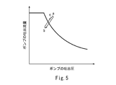
- the pump discharge flow rate repeatedly increases and decreases as shown in FIG. 5, and hunting may occur in the behavior of the hydraulic actuator.
- the operating point determined by the pump discharge pressure and the discharge flow rate exceeds the horsepower control line that defines the relationship between the pump discharge pressure and the horsepower control flow rate (point a in the figure)
- the inclination of the pump The turning angle is reduced.
- the pump discharge flow rate decreases and the pump discharge pressure decreases.
- the tilt angle of the pump is increased.
- an object of the present invention is to provide a hydraulic system that can suppress hunting of the behavior of the hydraulic actuator without causing adverse effects when the temperature of the hydraulic oil is low.
- a hydraulic system includes an operation device that outputs an operation signal corresponding to an operation amount with respect to an operation unit, a variable displacement pump, and a regulator that adjusts a tilt angle of the pump.
- the pressure sensor for detecting the discharge pressure of the pump, the discharge flow rate of the pump to the operation request flow rate according to the operation signal output from the operation device, and the discharge pressure of the pump detected by the pressure sensor.
- a control device that controls the regulator so as to be a smaller one of the corresponding horsepower control flow rates, and the control device defines a relationship between the discharge pressure of the pump and the horsepower control flow rate.
- One horsepower control line and a second horsepower control line lower than the first horsepower control line are stored, and the control device is a case where an operation signal output from the operation device is increased, and from the operation device
- the control device is a case where an operation signal output from the operation device is increased, and from the operation device
- the operation request flow rate according to the operated operation signal is larger than the horsepower control flow rate according to the pump discharge pressure detected by the pressure sensor, the pump discharge pressure detected by the pressure sensor and the pump Until the operating point determined by the discharge flow rate exceeds the first horsepower control line, the tilt angle of the pump is set to the tilt angle corresponding to the operation required flow rate, and the operating point exceeds the first horsepower control line.
- the tilt angle of the pump is reduced to the tilt angle determined by the first horsepower control line.
- the first horsepower control line which is a criterion for reducing the tilt angle of the pump when performing the horsepower control
- the first criterion for determining when the tilt angle of the pump should be increased.
- Hysteresis is provided between the two horsepower control lines. For this reason, when the tilt angle of the pump is changed and the operating point is shifted between the first horsepower control line and the second horsepower control line, the pump tilt angle is not changed any more. Accordingly, with a simple configuration that does not require additional parts, it is possible to suppress the increase and decrease of the pump discharge flow rate and to suppress the hunting of the behavior of the hydraulic actuator.
- this suppression of hunting is performed by electronic control by the control device without using parts such as a throttle whose characteristics change greatly depending on the temperature (especially at low temperatures). There will be no negative effects. Therefore, it is possible to realize a hydraulic system having excellent stability from a temperature lower than the temperature of the hydraulic oil to a normal working temperature (after the warm-up operation is finished).
- the control device When the operation signal output from the operating device increases, the control device is configured to discharge the pump with a pressure required for operation according to the operation signal output from the operating device.
- the hydraulic oil temperature is lower than a predetermined value even when the flow rate is higher than the horsepower control flow rate according to the above, the pump is tilted using the first horsepower control line without using the second horsepower control line.
- the turning angle may be decreased or increased. According to this configuration, it is possible to perform simple control using the first horsepower control line except when the temperature of the hydraulic oil is relatively high and hunting is likely to occur in the behavior of the hydraulic actuator. Can be used more.
- FIG. 1 is a schematic configuration diagram of a hydraulic system according to an embodiment of the present invention. It is a graph which shows the operation request
- FIG. 4A shows the change over time of the operation amount of the operating device
- FIG. 4B shows the change over time of the pump discharge flow rate. It is a graph which shows the motion of the operating point with respect to the horsepower control line in the conventional hydraulic system.
- FIG. 1 shows a hydraulic system 1 according to an embodiment of the present invention.
- the hydraulic system 1 is mounted on, for example, a construction machine such as a hydraulic excavator or a hydraulic crane, a civil engineering machine, an agricultural machine, or an industrial machine.
- the hydraulic system 1 includes a hydraulic actuator 5 and a pump 2 that supplies hydraulic oil to the hydraulic actuator 5 via a control valve 4.
- a hydraulic actuator 5 and a pump 2 that supplies hydraulic oil to the hydraulic actuator 5 via a control valve 4.
- the pump 2 is driven by the engine 21. However, the pump 2 may be driven by an electric motor.
- the pump 2 is a variable displacement pump (swash plate pump or oblique shaft pump) whose tilt angle can be changed. The tilt angle of the pump 2 is adjusted by the regulator 3.
- the pump 2 is connected to the control valve 4 by a supply line 11.
- the discharge pressure of the pump 2 is kept below the relief pressure by a relief valve (not shown).
- the hydraulic actuator 5 is a double-acting cylinder, and the control valve 4 is connected to the hydraulic actuator 5 by a pair of supply / discharge lines 12.
- the hydraulic actuator 5 may be a single-acting cylinder, and the control valve 4 may be connected to the hydraulic actuator 5 by a single supply / discharge line 12.
- the hydraulic actuator 5 may be a hydraulic motor.
- the control valve 4 is moved from the neutral position to the first position (position where the hydraulic actuator 5 is operated in one direction) or the second position (position where the hydraulic actuator 5 is operated in the reverse direction) by operating the operating device 6. Can be switched.
- the control valve 4 is a hydraulic pilot type and has a pair of pilot ports.
- the control valve 4 may be an electromagnetic pilot type.
- the operation device 6 includes an operation unit 61 and outputs an operation signal corresponding to an operation amount with respect to the operation unit 61. That is, the operation signal output from the controller device 6 increases as the operation amount increases.
- the operation unit 61 is, for example, an operation lever, but may be a foot pedal or the like.
- the operation device 6 is a pilot operation valve that outputs a pilot pressure as an operation signal. For this reason, the operating device 6 is connected to the pilot port of the control valve 4 by a pair of pilot lines 13. As the pilot pressure (operation signal) output from the operating device 6 increases, the opening area of the passage through which the control valve 4 supplies hydraulic oil to the hydraulic actuator 5 is increased.
- the regulator 3 described above is operated by an electric signal.
- the regulator 3 may electrically change the hydraulic pressure acting on the servo piston connected to the swash plate of the pump 2, or the swash plate of the pump 2. It may be an electric actuator connected to the.
- the regulator 3 is controlled by the control device 7.
- the control device 7 has a memory such as a ROM and a RAM and a CPU, and a program stored in the ROM is executed by the CPU.
- the control device 7 is electrically connected to the pressure sensor 8 provided in each of the pair of pilot lines 13 described above. However, in FIG. 1, only a part of the signal lines is drawn for simplification of the drawing.
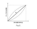
- the pressure sensor 8 detects the pilot pressure output from the operating device 6. Then, as shown in FIG. 2, the control device 7 determines an operation request flow rate Qa corresponding to the pilot pressure (operation signal) detected by the pressure sensor 8. That is, the operation request flow rate Qa increases as the pilot pressure increases.
- the operation request flow rate Qa is proportional to the pilot pressure.
- the relationship line between the operation request flow rate Qa and the operation signal is not necessarily a straight line, and may be a curve convex upward or downward as indicated by a broken line in FIG.
- the control device 7 is also electrically connected to a pressure sensor 9 provided on the supply line 11.
- the pressure sensor 9 detects the discharge pressure of the pump 2. Then, the control device 7 determines a horsepower control flow rate Qb corresponding to the discharge pressure of the pump 2 detected by the pressure sensor 9.
- the control device 7 stores a first horsepower control line L1 that defines the relationship between the discharge pressure of the pump 2 and the horsepower control flow rate Qb.
- the control device 7 determines the horsepower control flow rate Qb based on the first horsepower control line L1.
- the maximum value of the operation request flow rate Qa and the maximum value of the horsepower control flow rate Qb are substantially equal, but they may be different. This relationship is the same when each of the operating devices 6 is operated alone when a plurality of sets of the hydraulic actuator 5, the control valve 4, and the operating device 6 are provided.
- the control device 7 After determining the operation request flow rate Qa and the horsepower control flow rate Qb, the control device 7 controls the regulator 3 so that the discharge flow rate of the pump 2 becomes the smaller one of the operation request flow rate Qa and the horsepower control flow rate Qb.
- the control device 7 stores a second horsepower control line L2 lower than the first horsepower control line L1.
- the second horsepower control line L2 defines a second horsepower control flow rate that is lower than the horsepower control flow rate Qb described above.
- the second horsepower control line L2 is similar to the first horsepower control line L1.
- the second horsepower control line L2 defines a discharge flow rate of 70 to 98% of the first horsepower control line L1.
- the second horsepower control line L2 is not necessarily similar to the first horsepower control line L1.
- the interval between the first horsepower control line L1 and the second horsepower control line L2 may be small on the low discharge pressure side and large on the high discharge pressure side.
- the second horsepower control line L2 is used when the special acceleration condition is satisfied and the temperature of the hydraulic oil is higher than a predetermined value (for example, 40 to 50 ° C.).
- the special acceleration condition is satisfied when the operation signal output from the operation device 6 increases (when the operation amount of the operation device 6 increases to accelerate the hydraulic actuator 5). This is a case where the operation request flow rate Qa corresponding to the output operation signal is larger than the horsepower control flow rate Qb corresponding to the discharge pressure of the pump 2 detected by the pressure sensor 9.
- the first horsepower control line L1 is used. Also, when the special acceleration condition is not satisfied, that is, when the operation signal output from the operation device 6 is constant or decreases, only the first horsepower control line L1 is used. However, the second horsepower control line L2 may always be used regardless of the temperature of the hydraulic oil when the special acceleration condition is satisfied.
- the tilt angle of the pump 2 is decreased or increased so that the operating point determined by is maintained on the first horsepower control line L1.
- the discharge flow rate of the pump 2 is obtained by multiplying the pump discharge capacity per rotation obtained from the tilt angle of the pump 2 and the rotation speed of the engine 21.
- the temperature of the hydraulic oil may be detected by a temperature sensor provided in a tank that stores the hydraulic oil. Or the temperature sensor which detects atmospheric temperature is employ
- the control device 7 When the special acceleration condition is satisfied and the temperature of the hydraulic oil is higher than a predetermined value, the control device 7 operates based on the discharge pressure of the pump 2 detected by the pressure sensor 9 and the discharge flow rate of the pump 2. Until the point exceeds the first horsepower control line L1, the tilt angle of the pump 2 is set to the tilt angle corresponding to the operation request flow rate Qa.
- the control device 7 changes the tilt angle of the pump 2 by the tilt angle determined by the first horsepower control line L1 ( Until the current discharge pressure reaches a tilt angle corresponding to a point on the first horsepower control line L1.
- the control device 7 maintains the tilt angle of the pump 2. .
- the control device 7 changes the tilt angle of the pump 2, The tilt angle is increased until the tilt angle determined by the second horsepower control line L2 (the tilt angle corresponding to a point on the second horsepower control line L2 at the current discharge pressure) is reached.
- the control device 7 maintains the tilt angle of the pump 2. .
- the first horsepower control line L1 and the tilt angle of the pump 2 which are judgment criteria when the tilt angle of the pump 2 when performing horsepower control should be reduced.
- Hysteresis is provided between the second horsepower control line L2 which is a criterion for determining when to increase. For this reason, when the tilt angle of the pump 2 is changed and the operating point is shifted between the first horsepower control line L1 and the second horsepower control line L2, the tilt angle of the pump 2 is not changed any more. Therefore, with a simple configuration that does not require additional parts, it is possible to suppress the increase and decrease of the discharge flow rate of the pump 2 and to suppress the hunting of the behavior of the hydraulic actuator 5.
- the operating device when only the first horsepower control line L1 is used as in the prior art, after the warm-up operation is finished when the atmospheric temperature is low, the operating device is quickly and greatly operated as shown in FIG. As shown by a broken line in FIG. 4B, the discharge flow rate of the pump 2 repeatedly increases and decreases, and hunting occurs in the behavior of the hydraulic actuator.
- the second horsepower control line L2 is used in addition to the first horsepower control line L1 as in this embodiment, the discharge flow rate of the pump 2 is repeatedly increased and decreased as shown by the solid line in FIG. 4B. And hunting of the behavior of the hydraulic actuator 5 can be suppressed.
- the second horsepower control line L2 is not used, so the hydraulic oil temperature is relatively high and the hydraulic actuator 5 Except when hunting is likely to occur in the behavior, simple control using the first horsepower control line L1 can be performed, and more power from the engine 21 and the like can be used.
- the operation device 6 may be an electric joystick that outputs an electric signal as an operation signal to the control device 7.
- the pressure sensor 8 is unnecessary, and each pilot port of the control valve 4 is connected to the secondary pressure port of the electromagnetic proportional valve.
Landscapes
- Engineering & Computer Science (AREA)
- General Engineering & Computer Science (AREA)
- Mechanical Engineering (AREA)
- Physics & Mathematics (AREA)
- Fluid Mechanics (AREA)
- Civil Engineering (AREA)
- Mining & Mineral Resources (AREA)
- Structural Engineering (AREA)
- Chemical & Material Sciences (AREA)
- Analytical Chemistry (AREA)
- Computer Hardware Design (AREA)
- Fluid-Pressure Circuits (AREA)
- Control Of Positive-Displacement Pumps (AREA)
- Operation Control Of Excavators (AREA)
Abstract
Description
本発明は上述した実施形態に限定されるものではなく、本発明の要旨を逸脱しない範囲で種々の変形が可能である。
2 ポンプ
3 レギュレータ
4 制御弁
5 油圧アクチュエータ
6 操作装置
61 操作部
7 制御装置
8,9 圧力センサ
Claims (2)
- 操作部に対する操作量に応じた操作信号を出力する操作装置と、
可変容量型のポンプと、
前記ポンプの傾転角を調整するレギュレータと、
前記ポンプの吐出圧を検出する圧力センサと、
前記ポンプの吐出流量が、前記操作装置から出力される操作信号に応じた操作要求流量と、前記圧力センサで検出される前記ポンプの吐出圧に応じた馬力制御流量のうちの小さい方となるように、前記レギュレータを制御する制御装置と、を備え、
前記制御装置には、前記ポンプの吐出圧と前記馬力制御流量との関係を規定する第1馬力制御線と、これよりも低い第2馬力制御線が格納されており、
前記制御装置は、前記操作装置から出力される操作信号が増加した場合であって、前記操作装置から出力される操作信号に応じた操作要求流量が前記圧力センサで検出される前記ポンプの吐出圧に応じた馬力制御流量よりも大きな場合、前記圧力センサで検出されるポンプの吐出圧と前記ポンプの吐出流量とで定まる作動点が前記第1馬力制御線を超えるまでは前記ポンプの傾転角を前記操作要求流量に対応する傾転角とし、前記作動点が前記第1馬力制御線を越えたときは前記ポンプの傾転角を前記第1馬力制御線により定まる傾転角になるまで減少させ、前記作動点が前記第2馬力制御線を下回ったときは前記ポンプの傾転角を前記第2馬力制御線により定まる傾転角になるまで増加させ、前記第1馬力制御線を越えた前記作動点が前記第1馬力制御線と前記第2馬力制御線の間にシフトしたとき、または前記第2馬力制御線を下回った前記作動点が前記第1馬力制御線と前記第2馬力制御線の間にシフトしたときは、前記ポンプの傾転角を維持する、油圧システム。 - 前記制御装置は、前記操作装置から出力される操作信号が増加した場合であって、前記操作装置から出力される操作信号に応じた操作要求流量が前記圧力センサで検出される前記ポンプの吐出圧に応じた馬力制御流量よりも大きな場合でも、作動油の温度が所定値よりも低いときは、前記第2馬力制御線を使用せずに前記第1馬力制御線を使用して前記ポンプの傾転角を減少または増加させる、請求項1に記載の油圧システム。
Priority Applications (3)
| Application Number | Priority Date | Filing Date | Title |
|---|---|---|---|
| US16/619,007 US11041515B1 (en) | 2017-06-16 | 2018-06-14 | Hydraulic system |
| CN201880034891.9A CN110651123B (zh) | 2017-06-16 | 2018-06-14 | 油压系统 |
| GB2000659.9A GB2578554B (en) | 2017-06-16 | 2018-06-14 | Hydraulic system |
Applications Claiming Priority (2)
| Application Number | Priority Date | Filing Date | Title |
|---|---|---|---|
| JP2017118567A JP6970533B2 (ja) | 2017-06-16 | 2017-06-16 | 油圧システム |
| JP2017-118567 | 2017-06-16 |
Publications (1)
| Publication Number | Publication Date |
|---|---|
| WO2018230639A1 true WO2018230639A1 (ja) | 2018-12-20 |
Family
ID=64658638
Family Applications (1)
| Application Number | Title | Priority Date | Filing Date |
|---|---|---|---|
| PCT/JP2018/022720 Ceased WO2018230639A1 (ja) | 2017-06-16 | 2018-06-14 | 油圧システム |
Country Status (5)
| Country | Link |
|---|---|
| US (1) | US11041515B1 (ja) |
| JP (1) | JP6970533B2 (ja) |
| CN (1) | CN110651123B (ja) |
| GB (1) | GB2578554B (ja) |
| WO (1) | WO2018230639A1 (ja) |
Families Citing this family (1)
| Publication number | Priority date | Publication date | Assignee | Title |
|---|---|---|---|---|
| JP7798616B2 (ja) * | 2022-03-10 | 2026-01-14 | 川崎重工業株式会社 | コントローラおよびキャリブレーションシステム |
Citations (2)
| Publication number | Priority date | Publication date | Assignee | Title |
|---|---|---|---|---|
| JPH0777168A (ja) * | 1993-09-07 | 1995-03-20 | Hitachi Constr Mach Co Ltd | ポンプ制御装置 |
| JPH08121344A (ja) * | 1994-10-26 | 1996-05-14 | Hitachi Constr Mach Co Ltd | 油圧ポンプの傾転角制御装置 |
Family Cites Families (14)
| Publication number | Priority date | Publication date | Assignee | Title |
|---|---|---|---|---|
| KR930010906B1 (ko) * | 1989-12-14 | 1993-11-17 | 니뽄 에어브레이크 가부시끼가이샤 | 유압 모터의 제어 회로 |
| US5758499A (en) * | 1995-03-03 | 1998-06-02 | Hitachi Construction Machinery Co., Ltd. | Hydraulic control system |
| JPH09242707A (ja) * | 1996-03-05 | 1997-09-16 | Kayaba Ind Co Ltd | ロードセンシングシステム |
| JPH09287173A (ja) * | 1996-04-22 | 1997-11-04 | Sumitomo Constr Mach Co Ltd | 建設機械の油圧回路に於ける圧力ハンチング減衰制御装置 |
| JP4272485B2 (ja) * | 2003-08-28 | 2009-06-03 | 日立建機株式会社 | 建設機械のエンジンラグダウン抑制装置 |
| JP4413122B2 (ja) * | 2004-10-13 | 2010-02-10 | 日立建機株式会社 | 油圧建設機械の制御装置 |
| US8322481B2 (en) * | 2006-12-28 | 2012-12-04 | Hitachi Construction Machinery Co., Ltd. | Traveling control apparatus for hydraulic traveling vehicle |
| JP5084295B2 (ja) * | 2007-02-09 | 2012-11-28 | 日立建機株式会社 | 油圧建設機械のポンプトルク制御装置 |
| JP5015091B2 (ja) * | 2008-08-14 | 2012-08-29 | 日立建機株式会社 | 油圧作業機械のエンジンラグダウン抑制装置 |
| JP5585488B2 (ja) * | 2011-02-17 | 2014-09-10 | コベルコ建機株式会社 | ハイブリッド建設機械の動力源装置 |
| JP5736909B2 (ja) * | 2011-03-31 | 2015-06-17 | コベルコ建機株式会社 | 建設機械のポンプ制御装置 |
| JP2013002541A (ja) | 2011-06-15 | 2013-01-07 | Hitachi Constr Mach Co Ltd | 建設機械の制御装置 |
| JP5831830B2 (ja) * | 2011-08-11 | 2015-12-09 | Kyb株式会社 | 鉄道車両用制振装置 |
| JP6335093B2 (ja) * | 2014-10-10 | 2018-05-30 | 川崎重工業株式会社 | 建設機械の油圧駆動システム |
-
2017
- 2017-06-16 JP JP2017118567A patent/JP6970533B2/ja active Active
-
2018
- 2018-06-14 GB GB2000659.9A patent/GB2578554B/en active Active
- 2018-06-14 US US16/619,007 patent/US11041515B1/en active Active
- 2018-06-14 CN CN201880034891.9A patent/CN110651123B/zh not_active Expired - Fee Related
- 2018-06-14 WO PCT/JP2018/022720 patent/WO2018230639A1/ja not_active Ceased
Patent Citations (2)
| Publication number | Priority date | Publication date | Assignee | Title |
|---|---|---|---|---|
| JPH0777168A (ja) * | 1993-09-07 | 1995-03-20 | Hitachi Constr Mach Co Ltd | ポンプ制御装置 |
| JPH08121344A (ja) * | 1994-10-26 | 1996-05-14 | Hitachi Constr Mach Co Ltd | 油圧ポンプの傾転角制御装置 |
Also Published As
| Publication number | Publication date |
|---|---|
| US11041515B1 (en) | 2021-06-22 |
| JP6970533B2 (ja) | 2021-11-24 |
| GB2578554B (en) | 2022-04-27 |
| GB202000659D0 (en) | 2020-03-04 |
| CN110651123B (zh) | 2021-04-20 |
| GB2578554A (en) | 2020-05-13 |
| CN110651123A (zh) | 2020-01-03 |
| US20210189693A1 (en) | 2021-06-24 |
| JP2019002217A (ja) | 2019-01-10 |
Similar Documents
| Publication | Publication Date | Title |
|---|---|---|
| JP5771291B2 (ja) | 油圧閉回路システム | |
| US9546468B2 (en) | Hydraulic system of construction machine | |
| JP6279356B2 (ja) | 作業機械の油圧駆動装置 | |
| US11199260B2 (en) | Work vehicle and control method for work vehicle | |
| JP2019002451A (ja) | 油圧システム | |
| JP2016031125A (ja) | 建設機械の旋回制御装置 | |
| EP3099861A1 (en) | Engine and pump control device and working machine | |
| WO2018230642A1 (ja) | 油圧システム | |
| CN107429714A (zh) | 建筑机械的油压驱动系统 | |
| KR100651695B1 (ko) | 건설장비 제어방법 및 그 시스템 | |
| JP6970533B2 (ja) | 油圧システム | |
| JP6799480B2 (ja) | 油圧システム | |
| CN113286950A (zh) | 工程机械的回转驱动装置 | |
| JP6726127B2 (ja) | 油圧システム | |
| JP7257132B2 (ja) | 作業機械 | |
| JP6367677B2 (ja) | 油圧回路の制御装置及び油圧回路の制御方法 | |
| JP6619939B2 (ja) | 液圧駆動システム | |
| JPH04258505A (ja) | 油圧建設機械の駆動制御装置 | |
| JP2007298130A (ja) | 建設機械の油圧装置 | |
| WO2024161690A1 (ja) | 油圧システム | |
| JP2024007074A (ja) | 油圧ユニット | |
| JP2007298137A (ja) | 建設機械の油圧装置 | |
| JP2003314501A (ja) | 油圧駆動機械の制御装置 | |
| JP2016017594A (ja) | 液圧駆動システム |
Legal Events
| Date | Code | Title | Description |
|---|---|---|---|
| 121 | Ep: the epo has been informed by wipo that ep was designated in this application |
Ref document number: 18818007 Country of ref document: EP Kind code of ref document: A1 |
|
| NENP | Non-entry into the national phase |
Ref country code: DE |
|
| ENP | Entry into the national phase |
Ref document number: 202000659 Country of ref document: GB Kind code of ref document: A Free format text: PCT FILING DATE = 20180614 |
|
| 122 | Ep: pct application non-entry in european phase |
Ref document number: 18818007 Country of ref document: EP Kind code of ref document: A1 |