WO2018230197A1 - 車両搭載機器の制御装置 - Google Patents
車両搭載機器の制御装置 Download PDFInfo
- Publication number
- WO2018230197A1 WO2018230197A1 PCT/JP2018/017867 JP2018017867W WO2018230197A1 WO 2018230197 A1 WO2018230197 A1 WO 2018230197A1 JP 2018017867 W JP2018017867 W JP 2018017867W WO 2018230197 A1 WO2018230197 A1 WO 2018230197A1
- Authority
- WO
- WIPO (PCT)
- Prior art keywords
- cpu
- unit
- communication
- inter
- command signal
- Prior art date
- Legal status (The legal status is an assumption and is not a legal conclusion. Google has not performed a legal analysis and makes no representation as to the accuracy of the status listed.)
- Ceased
Links
Images




Classifications
-
- B—PERFORMING OPERATIONS; TRANSPORTING
- B60—VEHICLES IN GENERAL
- B60R—VEHICLES, VEHICLE FITTINGS, OR VEHICLE PARTS, NOT OTHERWISE PROVIDED FOR
- B60R16/00—Electric or fluid circuits specially adapted for vehicles and not otherwise provided for; Arrangement of elements of electric or fluid circuits specially adapted for vehicles and not otherwise provided for
- B60R16/02—Electric or fluid circuits specially adapted for vehicles and not otherwise provided for; Arrangement of elements of electric or fluid circuits specially adapted for vehicles and not otherwise provided for electric constitutive elements
- B60R16/023—Electric or fluid circuits specially adapted for vehicles and not otherwise provided for; Arrangement of elements of electric or fluid circuits specially adapted for vehicles and not otherwise provided for electric constitutive elements for transmission of signals between vehicle parts or subsystems
- B60R16/0231—Circuits relating to the driving or the functioning of the vehicle
-
- B—PERFORMING OPERATIONS; TRANSPORTING
- B62—LAND VEHICLES FOR TRAVELLING OTHERWISE THAN ON RAILS
- B62D—MOTOR VEHICLES; TRAILERS
- B62D5/00—Power-assisted or power-driven steering
- B62D5/04—Power-assisted or power-driven steering electrical, e.g. using an electric servo-motor connected to, or forming part of, the steering gear
- B62D5/0457—Power-assisted or power-driven steering electrical, e.g. using an electric servo-motor connected to, or forming part of, the steering gear characterised by control features of the drive means as such
- B62D5/0481—Power-assisted or power-driven steering electrical, e.g. using an electric servo-motor connected to, or forming part of, the steering gear characterised by control features of the drive means as such monitoring the steering system, e.g. failures
- B62D5/0484—Power-assisted or power-driven steering electrical, e.g. using an electric servo-motor connected to, or forming part of, the steering gear characterised by control features of the drive means as such monitoring the steering system, e.g. failures for reaction to failures, e.g. limp home
-
- B—PERFORMING OPERATIONS; TRANSPORTING
- B62—LAND VEHICLES FOR TRAVELLING OTHERWISE THAN ON RAILS
- B62D—MOTOR VEHICLES; TRAILERS
- B62D5/00—Power-assisted or power-driven steering
-
- B—PERFORMING OPERATIONS; TRANSPORTING
- B62—LAND VEHICLES FOR TRAVELLING OTHERWISE THAN ON RAILS
- B62D—MOTOR VEHICLES; TRAILERS
- B62D5/00—Power-assisted or power-driven steering
- B62D5/04—Power-assisted or power-driven steering electrical, e.g. using an electric servo-motor connected to, or forming part of, the steering gear
-
- B—PERFORMING OPERATIONS; TRANSPORTING
- B62—LAND VEHICLES FOR TRAVELLING OTHERWISE THAN ON RAILS
- B62D—MOTOR VEHICLES; TRAILERS
- B62D6/00—Arrangements for automatically controlling steering depending on driving conditions sensed and responded to, e.g. control circuits
-
- G—PHYSICS
- G06—COMPUTING OR CALCULATING; COUNTING
- G06F—ELECTRIC DIGITAL DATA PROCESSING
- G06F11/00—Error detection; Error correction; Monitoring
- G06F11/07—Responding to the occurrence of a fault, e.g. fault tolerance
-
- G—PHYSICS
- G06—COMPUTING OR CALCULATING; COUNTING
- G06F—ELECTRIC DIGITAL DATA PROCESSING
- G06F11/00—Error detection; Error correction; Monitoring
- G06F11/07—Responding to the occurrence of a fault, e.g. fault tolerance
- G06F11/0703—Error or fault processing not based on redundancy, i.e. by taking additional measures to deal with the error or fault not making use of redundancy in operation, in hardware, or in data representation
- G06F11/0793—Remedial or corrective actions
-
- G—PHYSICS
- G06—COMPUTING OR CALCULATING; COUNTING
- G06F—ELECTRIC DIGITAL DATA PROCESSING
- G06F11/00—Error detection; Error correction; Monitoring
- G06F11/07—Responding to the occurrence of a fault, e.g. fault tolerance
- G06F11/16—Error detection or correction of the data by redundancy in hardware
- G06F11/20—Error detection or correction of the data by redundancy in hardware using active fault-masking, e.g. by switching out faulty elements or by switching in spare elements
-
- G—PHYSICS
- G06—COMPUTING OR CALCULATING; COUNTING
- G06F—ELECTRIC DIGITAL DATA PROCESSING
- G06F11/00—Error detection; Error correction; Monitoring
- G06F11/30—Monitoring
-
- G—PHYSICS
- G06—COMPUTING OR CALCULATING; COUNTING
- G06F—ELECTRIC DIGITAL DATA PROCESSING
- G06F11/00—Error detection; Error correction; Monitoring
- G06F11/30—Monitoring
- G06F11/3003—Monitoring arrangements specially adapted to the computing system or computing system component being monitored
- G06F11/3024—Monitoring arrangements specially adapted to the computing system or computing system component being monitored where the computing system component is a central processing unit [CPU]
-
- G—PHYSICS
- G06—COMPUTING OR CALCULATING; COUNTING
- G06F—ELECTRIC DIGITAL DATA PROCESSING
- G06F11/00—Error detection; Error correction; Monitoring
- G06F11/30—Monitoring
- G06F11/3058—Monitoring arrangements for monitoring environmental properties or parameters of the computing system or of the computing system component, e.g. monitoring of power, currents, temperature, humidity, position, vibrations
-
- G—PHYSICS
- G07—CHECKING-DEVICES
- G07C—TIME OR ATTENDANCE REGISTERS; REGISTERING OR INDICATING THE WORKING OF MACHINES; GENERATING RANDOM NUMBERS; VOTING OR LOTTERY APPARATUS; ARRANGEMENTS, SYSTEMS OR APPARATUS FOR CHECKING NOT PROVIDED FOR ELSEWHERE
- G07C5/00—Registering or indicating the working of vehicles
- G07C5/006—Indicating maintenance
-
- G—PHYSICS
- G07—CHECKING-DEVICES
- G07C—TIME OR ATTENDANCE REGISTERS; REGISTERING OR INDICATING THE WORKING OF MACHINES; GENERATING RANDOM NUMBERS; VOTING OR LOTTERY APPARATUS; ARRANGEMENTS, SYSTEMS OR APPARATUS FOR CHECKING NOT PROVIDED FOR ELSEWHERE
- G07C5/00—Registering or indicating the working of vehicles
- G07C5/08—Registering or indicating performance data other than driving, working, idle, or waiting time, with or without registering driving, working, idle or waiting time
- G07C5/0808—Diagnosing performance data
-
- H—ELECTRICITY
- H02—GENERATION; CONVERSION OR DISTRIBUTION OF ELECTRIC POWER
- H02P—CONTROL OR REGULATION OF ELECTRIC MOTORS, ELECTRIC GENERATORS OR DYNAMO-ELECTRIC CONVERTERS; CONTROLLING TRANSFORMERS, REACTORS OR CHOKE COILS
- H02P29/00—Arrangements for regulating or controlling electric motors, appropriate for both AC and DC motors
- H02P29/02—Providing protection against overload without automatic interruption of supply
- H02P29/024—Detecting a fault condition, e.g. short circuit, locked rotor, open circuit or loss of load
- H02P29/028—Detecting a fault condition, e.g. short circuit, locked rotor, open circuit or loss of load the motor continuing operation despite the fault condition, e.g. eliminating, compensating for or remedying the fault
-
- B—PERFORMING OPERATIONS; TRANSPORTING
- B60—VEHICLES IN GENERAL
- B60R—VEHICLES, VEHICLE FITTINGS, OR VEHICLE PARTS, NOT OTHERWISE PROVIDED FOR
- B60R16/00—Electric or fluid circuits specially adapted for vehicles and not otherwise provided for; Arrangement of elements of electric or fluid circuits specially adapted for vehicles and not otherwise provided for
- B60R16/02—Electric or fluid circuits specially adapted for vehicles and not otherwise provided for; Arrangement of elements of electric or fluid circuits specially adapted for vehicles and not otherwise provided for electric constitutive elements
-
- B—PERFORMING OPERATIONS; TRANSPORTING
- B62—LAND VEHICLES FOR TRAVELLING OTHERWISE THAN ON RAILS
- B62D—MOTOR VEHICLES; TRAILERS
- B62D5/00—Power-assisted or power-driven steering
- B62D5/04—Power-assisted or power-driven steering electrical, e.g. using an electric servo-motor connected to, or forming part of, the steering gear
- B62D5/0421—Electric motor acting on or near steering gear
- B62D5/0424—Electric motor acting on or near steering gear the axes of motor and final driven element of steering gear, e.g. rack, being parallel
-
- B—PERFORMING OPERATIONS; TRANSPORTING
- B62—LAND VEHICLES FOR TRAVELLING OTHERWISE THAN ON RAILS
- B62D—MOTOR VEHICLES; TRAILERS
- B62D5/00—Power-assisted or power-driven steering
- B62D5/04—Power-assisted or power-driven steering electrical, e.g. using an electric servo-motor connected to, or forming part of, the steering gear
- B62D5/0457—Power-assisted or power-driven steering electrical, e.g. using an electric servo-motor connected to, or forming part of, the steering gear characterised by control features of the drive means as such
-
- G—PHYSICS
- G06—COMPUTING OR CALCULATING; COUNTING
- G06F—ELECTRIC DIGITAL DATA PROCESSING
- G06F11/00—Error detection; Error correction; Monitoring
Definitions
- the present invention relates to a control device for on-vehicle equipment.
- Patent Document 1 As a conventional control device for on-vehicle equipment, one described in Patent Document 1 below is known.
- the present invention has been devised in view of the above-described conventional technical problems, and provides a control device for a vehicle-mounted device capable of determining whether or not a CPU in which communication between CPUs is interrupted is in a reset state. To do.
- the present invention provides a first CPU state determination unit and a second CPU state determination unit that determine the state of one of the CPUs based on the state of communication between CPUs and the voltage value of a power supply or a reset signal. Is provided.
- the present invention it is possible to determine whether or not the CPU in which the inter-CPU communication is interrupted is in a reset state.
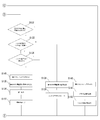
- FIG. 4 is a control block diagram of a first CPU and a second CPU shown in FIG. 3. It is a flowchart which shows the control content of the 1st CPU state judgment part and 2nd CPU state judgment part which are shown in FIG. It is a flowchart which shows the control content of the 1st CPU state judgment part and 2nd CPU state judgment part which are shown in FIG.
- FIG. 8 is a flowchart showing control details of abnormality determination of inter-CPU communication shown in FIGS. 5 to 7.
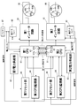
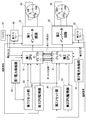
- FIG. 10 is a control block diagram of a first CPU state determination unit and a second CPU state determination unit shown in FIG. 9. It is a system block diagram of the control apparatus of the vehicle mounting apparatus which concerns on 2nd Embodiment of this invention.
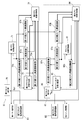
- FIG. 12 is a control block diagram of the first CPU and the second CPU shown in FIG. 11. It is a flowchart which shows the control content of the 1st CPU state judgment part and 2nd CPU state judgment part which are shown in FIG.
- control device for on-vehicle equipment according to the present invention will be described with reference to the drawings.
- the control device is applied to an electric power steering device of an automobile as in the conventional case.
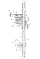
- FIG. 1 shows a system configuration diagram of a power steering apparatus to which the present invention is applied.
- the direction parallel to the rotation axis Z of the steering shaft 1 is “axial direction”
- the direction orthogonal to the rotation axis Z of the steering shaft 1 is “radial direction”
- the rotation axis Z of the steering shaft 1 The surrounding direction is described as “circumferential direction”.
- the “axial direction” will be described with the upper side in FIG. 1 as “one end side” and the lower side as “other end side”.
- the power steering apparatus includes a steering mechanism SM that is used for steering based on an operation by the driver, and a steering assist mechanism AM that assists the steering operation of the driver.
- the steering mechanism SM has a steering shaft 1 linked to a steering wheel (not shown) and a rack bar 2 as a turning shaft linked to a steered wheel (not shown).
- the steering shaft 1 and the rack bar 2 are These are linked via a conversion mechanism (not shown).
- the conversion mechanism is a so-called rack and pinion mechanism including pinion teeth (not shown) formed on the steering shaft 1 (output shaft 12 to be described later) and rack teeth (not shown) formed on the rack bar 2. .
- the steering shaft 1 is configured by connecting an input shaft 11 that rotates integrally with a steering wheel (not shown) and an output shaft 12 linked to the rack bar 2 by a torsion bar (not shown).
- the input shaft 11 has one axial end (upper end in FIG. 1) connected to a steering wheel (not shown) and the other end connected to a torsion bar (not shown).
- the output shaft 12 has one end in the axial direction (the upper end in FIG. 1) connected to a torsion bar (not shown) and the other end linked to the rack bar 2.
- pinion teeth are formed on the outer periphery on the other end side of the output shaft 12, and the pinion teeth mesh with rack teeth (not shown) formed on the outer side of the rack bar 2, so that the output shaft The rotation of 12 is converted into the axial movement of the rack bar 2 and transmitted.
- the rack bar 2 is accommodated on the inner peripheral side of a substantially cylindrical rack housing 20 extending along the axial direction, and both ends in the axial direction are not shown through tie rods 21 and 21 and a knuckle arm (not shown). It is linked to the steered wheels. That is, when the rack bar 2 moves in the axial direction, the knuckle arm (not shown) is pushed and pulled via the tie rods 21 and 21, thereby changing the direction of the steered wheels (not shown).
- the steering assist mechanism AM includes a so-called electromechanical integrated actuator that generates a steering assist force according to the driving state of the vehicle, a transmission mechanism 3 that transmits the steering assist force generated by the actuator to the rack bar 2 while decelerating, Have
- the actuator is based on the detection results of the electric motor 4 used for generating the steering assist force and various sensors (for example, the steering angle sensor AS, the torque sensor TS, and the vehicle speed sensor) used for detecting the driving state of the vehicle. And a control device 5 for controlling the driving of the motor.
- the steering angle sensor AS and the torque sensor TS are integrally configured as one unit and are arranged on the outer peripheral side of the steering shaft 1.
- the steering angle sensor AS detects a steering angle, which is a rotation amount from a neutral position of a steering wheel (not shown), based on a rotation angle difference between a pair of gears (not shown) that rotate as the input shaft 11 rotates.
- the torque sensor TS detects the steering torque input to the steering shaft 1 by the driver based on the relative rotational displacement amount between the input shaft 11 and the output shaft 12.
- the transmission mechanism 3 includes an input pulley 31, an output pulley 32, a belt member 33 wound between the pulleys 31 and 32, and the axial direction of the rack bar 2 while reducing the rotation of the output pulley 32. And a ball screw 34 for converting into motion.
- the input-side pulley 31 is fixed to the output shaft 43 of the electric motor 4 and rotates integrally with the output shaft 43 around a second reference axis A2 corresponding to the rotation axis of the output shaft 43.
- the output-side pulley 32 is disposed on the outer peripheral side of the rack bar 2, is linked to the rack bar 2 via a ball screw 34, and is a nut described later around a first reference axis A ⁇ b> 1 corresponding to the center axis of the rack bar 2. 341 and rotate together.
- the belt member 33 is an endless V-belt in which glass fiber, steel wire or the like is embedded as a core material, and the input-side pulley 31 is rotated by synchronously rotating the input-side pulley 31 and the output-side pulley 32. Is transmitted to the output-side pulley 32.
- the ball screw 34 includes a cylindrical nut 341 disposed on the outer peripheral side of the rack bar 2 and a plurality of balls provided so as to roll in a ball circulation groove 342 formed between the nut 341 and the rack bar 2. 343 and a tube (not shown) for connecting the both ends of the ball circulation groove 342 and for circulation of the ball 343.
- the ball circulation groove 342 includes a spiral shaft side ball screw groove 342 a provided on the outer periphery of the rack bar 2 and a spiral nut side ball screw groove 342 b provided on the inner periphery of the nut 341. .
- the electric motor 4 is a so-called three-phase alternating current surface magnet type synchronous motor, and has a cylindrical stator 41 fixed to the inner peripheral surface of the motor housing 40 and a predetermined radial clearance on the inner peripheral side of the stator 41. And a cylindrical rotor 42, and an output shaft 43 fixed to the inner peripheral side of the rotor 42.
- the motor housing 40 has a substantially cylindrical shape, and one end side is connected to a transmission mechanism housing portion 20a extending in the axial middle portion of the rack housing 20, and the other end side opening is closed by a control housing 50 described later. .
- the distal end side (transmission mechanism 3 side) of the output shaft 43 faces the transmission mechanism accommodating portion 20 a and is connected to the input side pulley 31.
- a motor rotation angle sensor (not shown) for detecting the rotation angle of the output shaft 43 is provided on the base end side (control device 5 side) of the output shaft 43. That is, the electric motor 4 is driven and controlled by the control device 5 by feeding back the detection result of the motor rotation angle sensor to the control device 5.
- a control board 51 on which electronic components such as microcomputers (first CPU 61 and second CPU 81 described later) for controlling the energization of the electric motor 4 are mounted is housed in a rectangular cylindrical control housing 50. And is connected and fixed to the opening on the other end side of the motor housing 40.
- the control board 51 is connected to the electric motor 4 and a motor rotation angle sensor (not shown) between the control housing 50 and the motor housing 40 (transmission mechanism housing portion 20 a) communicating with each other.
- the electric motor 4 is driven and controlled according to the steering torque, the vehicle speed, and the like based on the detection result of the sensor.
- the control housing 50 includes a cylindrical body 50a that covers the other end of the motor housing 40, and a cover 50b that closes the other end side opening of the body 50a.
- First Embodiment 2 to 8 show a first embodiment of the control device for on-vehicle equipment according to the present invention.
- FIG. 2 shows a system configuration diagram of the actuator of the power steering apparatus shown in FIG.
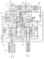
- FIG. 3 shows a first embodiment of the control device for on-vehicle equipment according to the present invention, and shows a system configuration diagram of the control device 5 shown in FIG.
- the actuator includes a first control unit 60 that drives and controls the first three-phase coil 68 surrounded by an alternate long and short dash line in FIG. 2, and a second controller that drives and controls the second three-phase coil 88. It is configured by a dual redundant system having two control units 80.
- the first control unit 60 is driven and controlled by a first CPU 61 that performs various calculations based on the power supply from the first power supply unit 63, and a pre-driver that is not shown, to which a command signal from the first CPU 61 is input.
- a first inverter circuit 62 On the other hand, the second control unit 80 is operated by a second CPU 81 that performs various calculations based on power supply from the second power supply unit 83 and a second pre-driver (not shown) to which a command signal from the second CPU 81 is input.
- a second inverter circuit 82 that is driven and controlled.
- the first CPU 61 is electrically connected to the main and sub sensors of the first torque sensor TS1, and receives first torque signals Tr1 (Main) and Tr1 (Sub) from the respective sensors. Receiving units T11 and T12 are provided.
- the first CPU 61 is electrically connected to the main and sub sensors of the first motor rotation angle sensor MS1, and receives the first motor rotation angle signals ⁇ m1 (Main) and ⁇ m1 (Sub) from the sensors.
- the first CPU 61 includes a vehicle signal receiving unit VS that receives various signals output from the vehicle, such as a vehicle speed signal.
- the second CPU 81 is electrically connected to the main and sub sensors of the second torque sensor TS2, and receives first torque signals Tr2 (Main) and Tr2 (Sub) from the respective sensors. Receiving units T21 and T22 are provided.
- the second CPU 81 is electrically connected to the main and sub sensors of the second motor rotation angle sensor MS2, and receives the first motor rotation angle signals ⁇ m2 (Main) and ⁇ m2 (Sub) from the sensors.
- Two second motor rotation angle signal receivers R21 and R22 are provided.
- first control unit 60 and the second control unit 80 include a first CPU monitoring unit 64 and a second CPU monitoring unit 84 that monitor the operating states of the first CPU 61 and the second CPU 81.
- the first CPU monitoring unit 64 and the second CPU monitoring unit 84 supply power to the first inverter circuit 62 and the second inverter circuit 82 when it is determined that an abnormality has occurred in the first CPU 61 and the second CPU 81 to be monitored, respectively. Has the function of blocking.
- the first CPU monitoring unit 64 outputs a cut-off signal to the first fail-safe relay 65 and the first inverter circuit 62 that are disposed between the on-vehicle battery BT and the first inverter circuit 62, so that the first inverter circuit The power supply to 62 is cut off.
- the second CPU monitoring unit 84 outputs a cut-off signal to the second fail-safe relay 85 and the second inverter circuit 82 disposed between the battery BT and the second inverter circuit 82, whereby the second inverter circuit The power supply to 82 is cut off.
- first control unit 60 and the second control unit 80 output the first reset signal Rs1 and the second reset signal Rs2 to the first CPU 61 and the second CPU 81 as necessary, and the first reset unit 66 and the second reset unit 86.
- the first reset unit 66 and the second reset unit 86 are responsible for initialization of the first CPU 61 and the second CPU 81 at a predetermined timing such as when the power is turned on or when an instantaneous power failure (voltage drop) occurs.
- the first CPU 61 and the second CPU 81 have a first inter-CPU communication unit 67 and a second inter-CPU communication unit 87 that perform inter-CPU communication that is transmission and reception of signals with the counterpart CPUs 61 and 81, respectively. That is, the operating states of the first CPU 61 and the second CPU 81 are mutually monitored by communicating with each other via the first inter-CPU communication unit 67 and the second inter-CPU communication unit 87.
- the first inter-CPU communication unit 67 and the second inter-CPU communication unit 87 employ different communication methods such as serial communication in the first inter-CPU communication unit 67 and parallel communication in the second inter-CPU communication unit 87, for example.
- the first inverter circuit 62 and the second inverter circuit 82 are configured by switching elements such as a MOS-FET, and a direct current supplied from the battery BT in response to a command signal from a corresponding predriver (not shown). Is converted into a three-phase alternating current and supplied to the first three-phase coil 68 and the second three-phase coil 88.
- the first inverter circuit 62 is electrically connected to the first and second first current detection units E11 and E12, and the current of the first inverter circuit 62 detected by the detection units E11 and E12 is the first. 1 is fed back to the CPU 61.
- the second inverter circuit 82 is electrically connected to the first and second second current detection units E21 and E22, and the current of the second inverter circuit 82 detected by the detection units E21 and E22 is detected. Feedback is provided to the second CPU 81.
- the electric motor 4 is a so-called three-phase induction motor that is driven based on three-phase AC power, and a first u-phase coil is formed on a tooth (not shown) formed on the inner peripheral side of the stator 41 (see FIG. 1).
- a first v-phase coil 68v, a first w-phase coil 68w, a second u-phase coil 88u, a second v-phase coil 88v, and a second w-phase coil 88w are wound.
- the stator 41 includes a first three-phase coil 68 composed of first u, v, w-phase coils 68u, 68v, 68w and a second three-phase coil 88 composed of second u, v, w-phase coils 88u, 88v, 88w. And having.
- the rotor 42 and the output shaft 43 are driven by these two systems of three-phase coils 68 and 88.
- FIG. 4 shows a control block diagram of the first CPU 61 and the second CPU 81 shown in FIG.
- the first CPU 61 includes a first CPU failure diagnosis unit 71, a first inter-CPU communication unit 67, a first inter-CPU communication diagnosis unit 72, a second CPU reset state determination unit 73, and a second CPU state determination unit. 74, a first command signal calculation unit 75, and a first reset execution unit 76.
- the first CPU failure diagnosis unit 71 detects an abnormal state of the first CPU 61 and outputs the information to the first CPU monitoring unit 64.
- the first CPU monitoring unit 64 determines that an abnormality has occurred in the first CPU 61, as described above, the first CPU monitoring unit 64 outputs a cutoff signal to the first failsafe relay 65 and the first inverter circuit 62, and supplies power from the battery BT. Shut off.
- the first CPU failure diagnosis unit 71 outputs a diagnosis result to the first inter-CPU communication unit 67 (a first first inter-CPU communication unit 67a and a second first inter-CPU communication unit 67b described later), and the first CPU 61 is abnormal. Is transmitted to the second CPU 81.
- the first inter-CPU communication unit 67 is configured by a duplex system including a first first inter-CPU communication unit 67a and a second first inter-CPU communication unit 67b. Further, when the second CPU state determination unit 74 determines that the second CPU 81 has returned from the reset state by the mutual monitoring, the first inter-CPU communication unit 67 synchronizes the second CPU 81 for synchronizing the mutual control timing. Output a signal.
- the first inter-CPU communication diagnostic unit 72 includes a first first inter-CPU communication diagnostic unit 72a and a second first inter-CPU communication diagnostic unit 72b. Then, normality / abnormality of the first inter-CPU communication through the first first inter-CPU communication unit 67a is judged by the first first inter-CPU communication diagnostic unit 72a, and the second first inter-CPU communication diagnostic unit 72b The normality / abnormality of the second inter-CPU communication through the second first inter-CPU communication unit 67b is determined.
- the second CPU reset state determination unit 73 determines that the second CPU 81 is in the reset state based on a predetermined condition
- the second CPU reset state determination unit 73 outputs the information to the second CPU state determination unit 74.
- the second CPU reset state determination unit 73 detects a state in which the voltage VB supplied from the battery BT is lower than a predetermined value, and the first CPU communication diagnosis unit 72a and the first When the communication stop state of the second first inter-CPU communication diagnostic unit 72b continues for a predetermined time or more, it is determined that the second CPU 81 is in the reset state.
- the second CPU state determination unit 74 determines the state of the communication function of the first CPU 61 based on the diagnosis results of the first first inter-CPU communication diagnosis unit 72a and the second first inter-CPU communication diagnosis unit 72b.
- the normality / abnormality of the second CPU 81 is determined based on information on the first inter-CPU communication and the second inter-CPU communication through the first inter-CPU communication unit 67a and the second first inter-CPU communication unit 67b. That is, this determination is executed when the diagnosis results of the first first inter-CPU communication diagnostic unit 72a and the second first inter-CPU communication diagnostic unit 72b are both normal.
- the second CPU 81 As specific determination criteria for normality / abnormality of the second CPU 81, communication between the CPUs of the first first inter-CPU communication unit 67a and the second first inter-CPU communication unit 67b (the first inter-CPU communication and the second inter-CPU communication) When it is recognized that both the CPU communication is normal, it is determined that the second CPU 81 is normal. On the other hand, it was recognized that each of the first inter-CPU communication units 67a and the second first inter-CPU communication unit 67b (the first inter-CPU communication and the second inter-CPU communication) was abnormal. In this case, it is determined that the second CPU 81 is abnormal.
- one inter-CPU communication is normal. If the determination that the other inter-CPU communication is abnormal is wrong, it is determined that the other inter-CPU communication is abnormal.
- the normality / abnormality of the second CPU 81 is, for example, whether or not a predetermined variable is transmitted from the first first inter-CPU communication unit 67a and the second first inter-CPU communication unit 67b, and the same value is transmitted on the receiving side. Judgment can be made.
- the second CPU state determination unit 74 the reset state of the second CPU 81, the abnormality of the second CPU 81, and the first inter-CPU communication through the first inter-CPU communication unit 67a and the second inter-CPU communication unit 67b.
- the first control unit 60 shifts the drive control of the electric motor 4 to a state of continuing, blocking, or reducing the output, and displays a warning on the vehicle side as necessary.
- the first command signal calculator 75 is fetched from the first and second first torque signal receivers T11 and T12 (see FIG. 3) and the vehicle signal receiver VS (see FIG. 3). Based on the vehicle speed signal, the first basic command signal Ib1 is calculated with reference to a predetermined assist control amount Map (not shown). Moreover, the 1st command signal calculating part 75 calculates the 1st control command signal Ic1 which is a command signal which controls the 1st inverter circuit 62, when the 2nd CPU state judgment part 74 judges that communication between CPUs is abnormal.
- the first command signal calculation unit 75 calculates the first command signal Io1 including the first basic command signal Ib1, the first control command signal Ic1, and the like, and based on the first command signal Io1, the first inverter The electric motor 4 is driven and controlled via the circuit 62.
- the first command signal calculation unit 75 calculates the second command signal Io2 at least until the second CPU 81 returns. That is, when it is determined that the second CPU 81 is in the reset state, the assist control is continued only by the first CPU 61 until the second CPU 81 restarts and returns. Note that after the second CPU 81 returns, the assist control may be continued by both the first CPU 61 and the second CPU 81, or may be shifted to other control.
- the first reset executing unit 76 executes the reset of the first CPU 61 based on the first reset signal Rs1 input to the first reset signal receiving unit R1 of the first CPU 61.
- the CPU reset itself is based on the hardware function of the first CPU 61. Further, when the second CPU state determination unit 74 determines that the second CPU 81 is in the reset state, the first reset execution unit 76 executes the reset of the first CPU 61 along with the reset of the second CPU 81.
- the second CPU 81 is configured similarly to the first CPU 61. That is, the second CPU 81 includes a second CPU failure diagnosis unit 91, a second inter-CPU communication unit 87, a second inter-CPU communication diagnosis unit 92, a first CPU reset state determination unit 93, a first CPU state determination unit 94, and a second CPU. A command signal calculation unit 95 and a second reset execution unit 96 are provided.
- the second CPU failure diagnosis unit 91 detects an abnormal state of the second CPU 81 and outputs the information to the second CPU monitoring unit 84.
- the second CPU monitoring unit 84 determines that an abnormality has occurred in the second CPU 81, as described above, the second CPU monitoring unit 84 outputs a cutoff signal to the second fail-safe relay 85 and the second inverter circuit 82, and supplies power from the battery BT. Shut off.
- the second CPU failure diagnosis unit 91 outputs a diagnosis result to the second inter-CPU communication unit 87 (a first second inter-CPU communication unit 87a and a second second inter-CPU communication unit 87b described later), and the second CPU 81 is abnormal. Is transmitted to the first CPU 61.
- the second inter-CPU communication unit 87 is configured by a duplex system including a first second inter-CPU communication unit 87a and a second second inter-CPU communication unit 87b. Further, when the first CPU state determination unit 94 determines that the first CPU 61 has returned from the reset state by the mutual monitoring, the second inter-CPU communication unit 87 synchronizes the first CPU 61 with the mutual control timing. Output a signal.
- the second inter-CPU communication diagnostic unit 92 includes a first second inter-CPU communication diagnostic unit 92a and a second second inter-CPU communication diagnostic unit 92b. Then, normality / abnormality of the first inter-CPU communication through the first second inter-CPU communication unit 87a is judged by the first second inter-CPU communication diagnostic unit 92a, and the second second inter-CPU communication diagnostic unit 92b The normality / abnormality of the second inter-CPU communication through the second second inter-CPU communication unit 87b is determined.
- the first CPU reset state determination unit 93 determines that the first CPU 61 is in the reset state based on a predetermined condition
- the first CPU reset state determination unit 93 outputs the information to the first CPU state determination unit 94.
- the first CPU reset state determination unit 93 detects a state in which the voltage VB supplied from the battery BT is lower than a predetermined value, and detects the first second inter-CPU communication diagnosis unit 92a and the first CPU When the communication stop state of the second second inter-CPU communication diagnosis unit 92b continues for a predetermined time or more, it is determined that the first CPU 61 is in the reset state.
- the first CPU state determination unit 94 determines the state of the communication function of the second CPU 81 based on the diagnosis results of the first second inter-CPU communication diagnosis unit 92a and the second second inter-CPU communication diagnosis unit 92b.
- the normality / abnormality of the first CPU 61 is determined based on information on the first inter-CPU communication and the second inter-CPU communication through the second inter-CPU communication unit 87a and the second second inter-CPU communication unit 87b. That is, this determination is executed when the diagnosis results of the first second inter-CPU communication diagnostic unit 92a and the second second inter-CPU communication diagnostic unit 92b are both normal.
- the first CPU 61 As specific judgment criteria for normality / abnormality of the first CPU 61, communication between the CPUs of the first second inter-CPU communication unit 87a and the second second inter-CPU communication unit 87b (the first inter-CPU communication and the second inter-CPU communication) When it is recognized that both the CPU communication is normal, it is determined that the first CPU 61 is normal. On the other hand, the inter-CPU communication (the first inter-CPU communication and the second inter-CPU communication) of the first second inter-CPU communication unit 87a and the second second inter-CPU communication unit 87b are recognized as abnormal. In this case, it is determined that the first CPU 61 is abnormal.
- one inter-CPU communication is normal. If the determination is wrong that the other CPU communication is abnormal, it is determined that the other CPU communication is abnormal.
- the normality / abnormality of the first CPU 61 is, for example, whether or not a predetermined variable is transmitted from the first second inter-CPU communication unit 87a and the second second inter-CPU communication unit 87b, and the same value is transmitted on the receiving side. Judgment can be made.
- the second control unit 80 shifts the drive control of the electric motor 4 to a state of continuing, blocking, or reducing the output, and displays a warning on the vehicle side as necessary.
- the second command signal calculation unit 95 is fetched from the first and second torque signal receiving units T21 and T22 (see FIG. 3) and the vehicle signal receiving unit VS (see FIG. 3). Based on the obtained vehicle speed signal, the second basic command signal Ib2 is calculated with reference to a predetermined assist control amount Map (not shown). The second command signal calculation unit 95 calculates a second control command signal Ic2 that is a command signal for controlling the second inverter circuit 82 when the first CPU state determination unit 94 determines that the communication between CPUs is abnormal.
- the second command signal calculation unit 95 calculates the second command signal Io2 including the second basic command signal Ib2, the second control command signal Ic2, and the like, and based on the second command signal Io2, the second inverter The electric motor 4 is driven and controlled via the circuit 82.
- the second command signal calculation unit 95 calculates the second command signal Io2 at least until the first CPU 61 returns. That is, when the first CPU 61 is determined to be in the reset state, the assist control is continued only by the second CPU 81 until the first CPU 61 restarts and returns. After the first CPU 61 returns, the assist control may be continued by both the first CPU 61 and the second CPU 81, or may be shifted to another control.
- the second reset execution unit 96 executes the reset of the second CPU 81 based on the second reset signal Rs2 input to the second reset signal reception unit R2 of the second CPU 81.
- the CPU reset itself is based on the hardware function of the second CPU 81. Further, when the first CPU state determination unit 94 determines that the first CPU 61 is in the reset state, the second reset execution unit 96 executes the reset of the second CPU 81 along with the reset of the first CPU 61.
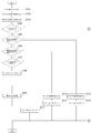
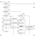
- FIG. 5 to 7 show a series of flowcharts showing the control contents of the first CPU state determination unit 94 and the second CPU state determination unit 74.
- FIG. Here, both control contents of the first CPU state determination unit 94 and the second CPU state determination unit 74 are common. Therefore, in the following, for convenience, only the control content of the second CPU state determination unit 74 will be described, and the detailed description of the control content of the first CPU state determination unit 94 will be omitted.
- step S101 After reading the battery voltage VB (step S101), the information of the first inter-CPU communication is captured (step S102), and further the second inter-CPU communication information. (Step S103).
- step S104 it is determined whether or not the reset flag Fr2 related to the other CPU (second CPU 81 in the present embodiment) is set (step S104). If it is determined Yes, the process proceeds to step S115.
- step S104 it is subsequently determined whether or not the first communication between CPUs, that is, the first CPU communication error flag Fc1 is set (step S105). ).
- the specific contents of the first abnormality determination of communication between the CPUs will be described later in detail using the sub-flowchart shown in FIG. 8 (hereinafter, the same in this control flow).
- step S105 If it is determined No in step S105, the second inter-CPU communication return process is executed (step S113), and then the reset state counter Cr is incremented (step S114), and this program is terminated.
- the second CPU inter-communication return processing includes, for example, initialization of a predetermined RAM, synchronization of a communication cycle, and the like (hereinafter the same in this control flow).
- step S105 it is subsequently determined whether or not the second inter-CPU communication abnormality, that is, the second inter-CPU communication abnormality flag Fc2 is set (step S106).
- the abnormality determination of the second inter-CPU communication is the same as the abnormality determination of the first inter-CPU communication (hereinafter the same in this control flow).
- step S111 the first inter-CPU communication return process is executed (step S111), and then the reset state counter Cr is incremented (step S112), and this program is terminated.
- the first inter-CPU communication return processing is, for example, initialization of a predetermined RAM, synchronization of a communication cycle, etc., as in the first inter-CPU communication return processing (hereinafter the same in this control flow). ).
- step S106 it is subsequently determined whether or not the battery voltage VB is below a predetermined value Vx (step S107).
- the predetermined value Vx is set to “5 to 6 volts”.
- step S107 a reset signal is output, that is, the reset flag Fr2 is set (step S108), and then the state of its own CPU (the first CPU 61 in this embodiment) is detected (step S108). S109), this program ends.
- the reset state of the second CPU 81 is determined based on the information on the first inter-CPU communication and the battery voltage VB.
- step S104 it is determined whether or not the battery voltage VB is equal to or higher than a predetermined value Vx as shown in FIG. 6 (step S115). Ends this program.
- step S115 it is subsequently determined whether or not the first inter-CPU communication abnormality flag Fc1 is set as in step S105 (step S116). If it is determined No, the process proceeds to step S132.
- step S116 it is subsequently determined whether or not the second inter-CPU communication abnormality flag Fc2 is set as in step S106 (step S117).
- step S117 it is subsequently determined whether or not the reset state counter Cr is equal to or greater than a predetermined value Cx (step S125).
- the reset state counter Cr is a so-called timer counter.
- the predetermined value Cx is set to “1 second”.
- step S125 the first inter-CPU communication return process is executed (step S130), and then the reset state counter Cr is incremented (step S131), and this program is terminated.
- step S125 it is subsequently determined whether or not the battery voltage VB is equal to or higher than a predetermined value Vx (step S126). When it is determined No, the program is terminated. To do.
- step S126 If it is determined Yes in step S126, the reset flag Fr2 is released (step S144), then the first abnormality determination of inter-CPU communication is confirmed (step S127), and the assist control is continued. Then, a warning is output about the abnormality in the first inter-CPU communication (step S128), the content of the abnormality is output (step S129), and the program is terminated.
- the assist control is continued, the assist control is continued as it is, and for example, the assist control may be continued by reducing the output of the electric motor 4 (the same applies to the present control flowchart).
- step S118 If it is determined Yes in step S117, it is then determined whether or not the reset state counter Cr is equal to or greater than a predetermined value Cx (step S118).
- step S122 If it is determined No, the first inter-CPU communication return process is executed (step S122), the second inter-CPU communication return process is executed (step S123), and then the reset state counter is executed. Cr is incremented (step S124), and this program ends.
- step S118 if it is determined Yes in step S118, after the reset flag Fr2 is canceled (step S143), the abnormality determination of the first CPU itself is confirmed (step S119), and the assist control is continued. Then, a warning is output about the abnormality of the first CPU itself (step S120), the contents of the abnormality are output (step S121), and the program is terminated.
- step S116 it is determined whether or not the second inter-CPU communication abnormality flag Fc2 is set as shown in FIG. 7 (step S132). If it is determined No, the reset flag Fr2 is canceled (step S140), the normal determination of the first CPU is confirmed (step S141), and then the reset occurrence record is output (step S142). Exit the program.
- step S132 it is subsequently determined whether or not the reset state counter Cr is equal to or greater than a predetermined value Cx (step S133). If it is determined No, the second CPU inter-communication return processing is executed (step S138), and then the reset state counter Cr is incremented (step S139), and the program is terminated.
- step S133 it is subsequently determined whether or not the battery voltage VB is equal to or higher than the predetermined value Vx (step S134). If it is determined No, the program is terminated. To do.
- step S134 If it is determined Yes in step S134, the reset flag Fr2 is released (step S145), then the second CPU communication abnormality determination is confirmed (step S135), and the assist control is continued. Then, a warning is output regarding the abnormality of the second inter-CPU communication (step S136), the content of the abnormality is output (step S137), and the program is terminated.
- FIG. 8 shows a flowchart showing the control contents related to the abnormality determination of the first inter-CPU communication and the second inter-CPU communication.
- the abnormality determination of the first inter-CPU communication and the second inter-CPU communication is common. For this reason, in the following, for the sake of convenience, only the abnormality determination of the second inter-CPU communication will be described, and a specific description of the abnormality determination of the first inter-CPU communication will be omitted.
- step S201 it is first determined whether or not the previous communication data update counter Cb and the current communication data update counter Cn do not match.
- step S210 it is determined whether or not the first timer counter Tm1 is equal to or greater than a predetermined value Tx1 (step S210). If YES is determined, the reset flag Fr2 is set (step S218), the abnormal state of the second inter-CPU communication is determined, and the program is terminated.
- step S210 when it is determined No in step S210, the first timer counter Tm1 is incremented (step S211), and the process proceeds to step S203.
- step S201 If it is determined Yes in step S201, the first timer counter Tm1 is cleared (step S202), and then the process proceeds to step S203.
- step S203 it is determined whether or not the communication data length Dl is equal to or less than a predetermined value Dx (step S203).
- step S212 it is determined whether or not the second timer counter Tm2 is equal to or greater than a predetermined value Tx2 (step S212). If YES is determined, the reset flag Fr2 is set (step S218), the abnormal state of the second inter-CPU communication is determined, and the program is terminated.
- step S212 the second timer counter Tm2 is incremented (step S213), and the process proceeds to step S205.
- step S203 If it is determined Yes in step S203, the second timer counter Tm2 is cleared (step S204), and then the process proceeds to step S205.
- step S205 it is determined whether or not the received CRC matches the transmitted CRC (step S205).
- step S214 it is determined whether or not the third timer counter Tm3 is equal to or greater than a predetermined value Tx3 (step S214). If YES is determined, the reset flag Fr2 is set (step S218), the abnormal state of the second inter-CPU communication is determined, and the program is terminated.
- step S214 if it is determined No in step S214, the third timer counter Tm3 is incremented (step S215), and the process proceeds to step S207.
- step S205 If it is determined Yes in step S205, the third timer counter Tm3 is cleared (step S206), and then the process proceeds to step S207.
- step S207 it is determined whether or not the communication status is normal (step S207).
- the communication self-diagnosis is NG, and subsequently, it is determined whether or not the fourth timer counter Tm4 is equal to or greater than the predetermined value Tx4 (step S216). If YES is determined, the reset flag Fr2 is set (step S218), the abnormal state of the second inter-CPU communication is determined, and the program is terminated.
- step S216 if it is determined No in step S216, the fourth timer counter Tm4 is incremented (step S217), and the process proceeds to step S209.
- step S207 If it is determined Yes in step S207, the fourth timer counter Tm4 is cleared (step S208), and the process proceeds to step S209.
- step S209 the reset flag Fr2 is canceled (step S209), the normal state of the second inter-CPU communication is determined, and this program is terminated.
- the vehicle mounted device control apparatus can solve the problems of the conventional vehicle mounted device control apparatus by providing the following effects.
- control device (control device 5) for on-vehicle equipment is a control device for on-vehicle equipment, and a command signal for controlling the electric motor 4 that is a drive unit of the power steering device that is the on-vehicle equipment.
- the first CPU 61 and the second CPU 81 that calculate the first command signal Io1 and the second command signal Io2), the first reset unit 66 that outputs the first reset signal Rs1 to the first CPU 61, and the second reset signal Rs2 to the second CPU 81 Is provided in the first CPU 61, the first inter-CPU communication unit 67 that performs inter-CPU communication that is transmission and reception of signals performed between the first CPU 61 and the second CPU 81, and the second CPU 81.
- a second inter-CPU communication unit 87 that performs inter-CPU communication, and a first power supply that supplies power to the first CPU 61.
- a second CPU state determination unit 74 that determines the state of the second CPU 81 based on the second reset signal Rs2, and the state of communication between the CPUs and the power supplied from the second power supply unit 83.
- a first CPU state determination unit 94 that determines the state of the first CPU 61 based on the voltage value (battery voltage VB) or the first reset signal Rs1.
- the first CPU state determination unit 94 stops or disables inter-CPU communication, and the voltage value (battery voltage VB) of power supplied from the second power supply unit 83 is equal to or greater than a predetermined value Vx.
- the first reset signal Rs1 is not output, it is determined that the first CPU 61 is abnormal, and the second CPU state determination unit 74 stops or disables inter-CPU communication, and the voltage of power supplied from the first power supply unit 63
- the value (battery voltage VB) is equal to or greater than the predetermined value Vx and the second reset signal Rs2 is not output, it is determined that the second CPU 81 is abnormal.
- the first CPU state determination unit 94 determines whether there is an abnormality in the first CPU 61 based on a signal transmitted from the first CPU 61 when inter-CPU communication is possible, and the second CPU state determination unit 74 When communication between CPUs is possible, the presence / absence of abnormality of the second CPU 81 is determined based on a signal transmitted from the second CPU 81.
- step S109 the result of the self-diagnosis function (see step S109) of each of the CPUs 61 and 81 is reflected on the other CPU by making a determination based on the information on the communication between the CPUs.
- the subsequent processing can be performed appropriately.
- the first CPU 61 includes a first command signal calculation unit 75 that calculates a first command signal Io1 that is a command signal for controlling the electric motor 4 corresponding to the drive unit, and the second CPU 81
- a second command signal calculation unit 95 that calculates a second command signal Io2, which is a command signal for controlling the electric motor 4 corresponding to the drive unit, is provided. 2
- the CPU 81 When determining that the CPU 81 is abnormal, it calculates a command signal (first command signal Io1) for controlling the electric motor 4 corresponding to the drive unit, and the second command signal calculation unit 95 is the first CPU state determination unit 94
- a command signal (second command signal Io2) for controlling the electric motor 4 corresponding to the drive unit is calculated.
- the assist control is continued with the other CPU (see steps S119 to S120), thereby improving the convenience for the driver. it can.
- the first CPU monitoring unit 64 that determines whether or not the first CPU 61 is abnormal is provided, and the second CPU monitoring unit 84 that determines whether or not the second CPU 81 is abnormal.
- the first CPU state determining unit 94 is a CPU. The first CPU 61 when inter-communication is impossible and the voltage value (battery voltage VB) of the power supplied from the second power supply unit 83 is greater than or equal to the predetermined value Vx, or when the first CPU monitoring unit 64 determines that the first CPU 61 is abnormal.
- the second CPU state determination unit 74 determines that the communication between CPUs is impossible and the voltage value of the power supplied from the first power supply unit 63 (battery voltage VB) is equal to or higher than the predetermined value Vx, or the second CPU When the monitoring unit 84 determines that the second CPU 81 is abnormal, it determines that the second CPU 81 is abnormal.
- the first and second CPU state determination units 74 and 94 cannot perform inter-CPU communication, and the battery voltage VB supplied from the first and second power supply units 63 and 83 is a predetermined value.
- Vx or higher it can be determined that one of the CPUs is abnormal. Thereby, subsequent processing in the other CPU can be appropriately performed.
- the first CPU 61 includes a first command signal calculation unit 75 that calculates a first command signal Io1 that is a command signal for controlling the electric motor 4 corresponding to the drive unit, and the second CPU 81 A second command signal calculation unit that calculates a second command signal Io2, which is a command signal for controlling the electric motor 4 corresponding to the drive unit, is provided.
- the first command signal calculation unit 75 includes a second CPU state determination unit 74 and a second CPU 81. Is determined to be abnormal, a command signal (first command signal Io1) for controlling the electric motor 4 corresponding to the drive unit is calculated, and the second command signal calculation unit 95 is configured such that the first CPU state determination unit 94 uses the first CPU 61.
- a command signal (second command signal Io2) for controlling the electric motor 4 corresponding to the drive unit is calculated.
- the assist control is continued with the other CPU (see steps S119 to S120), thereby improving the convenience for the driver. it can.
- the first inter-CPU communication unit 67 includes a first first inter-CPU communication unit 67a and a second first inter-CPU communication unit 67b
- the second inter-CPU communication unit 87 includes the first first CPU inter-communication unit 67b.
- the second inter-CPU communication is performed between the first second inter-CPU communication unit 87a that performs the first inter-CPU communication with the inter-CPU communication unit 67a and the second first inter-CPU communication unit 67b. 2 second inter-CPU communication unit 87b.
- the reliability of the control device 5 can be improved.
- the first CPU monitoring unit 64 that determines whether there is an abnormality in the first CPU 61 and the second CPU monitoring unit 84 that determines whether there is an abnormality in the second CPU 81 are provided.
- the voltage value of the power supplied from the second power supply unit 83 battery voltage VB
- the first CPU monitoring unit 64 When the first CPU 61 is determined to be abnormal and the first inter-CPU communication and the second inter-CPU communication are not possible, the first CPU 61 is determined to be abnormal, and the second CPU state determination unit 74 performs the first inter-CPU communication and the second inter-CPU communication.
- the first and second CPU state determination units 74 and 94 cannot perform inter-CPU communication, and the battery voltage VB supplied from the first and second power supply units 63 and 83 is a predetermined value.
- Vx or higher it can be determined that one of the CPUs is abnormal. Thereby, subsequent processing in the other CPU can be appropriately performed.
- the first CPU state determination unit 94 cannot perform the first inter-CPU communication and the second inter-CPU communication, and the voltage value of the power supplied from the second power supply unit 83 (battery voltage VB). ) Is less than the predetermined value Vx, it is determined that the first CPU 61 is in the reset state, and the second CPU state determination unit 74 cannot perform the first inter-CPU communication and the second inter-CPU communication, and the first power supply unit When the voltage value (battery voltage VB) of the power supplied from 63 is less than the predetermined value Vx, it is determined that the second CPU 81 is in the reset state.
- the first and second CPU state determination units 74 and 94 cannot perform inter-CPU communication, and the battery voltage VB supplied from the first and second power supply units 63 and 83 is less than the predetermined value Vx. At this time, it can be determined that one of the CPUs is in a reset state. Thereby, subsequent processing in the other CPU can be appropriately performed.
- the first CPU state determination unit 94 or the second CPU state determination unit 74 is capable of communicating one of the first inter-CPU communication and the second inter-CPU communication and disabling the other. It is determined that the other is abnormal among the first inter-CPU communication and the second inter-CPU communication.
- both the first and second inter-CPU communications are in a communication disabled state. It can be determined that the communication is abnormal. Thereby, subsequent processing can be performed appropriately.
- the first inter-CPU communication unit 67 and the second inter-CPU communication unit 87 have different communication methods.
- the first inter-CPU communication unit 67 and the second inter-CPU communication unit 87 have different communication methods, so that the simultaneous failure of the first inter-CPU communication unit 67 and the second inter-CPU communication unit 87 due to a common cause can be prevented. Can be suppressed.
- the first CPU 61 includes a first command signal calculation unit 75 that calculates a first command signal Io1 that is a command signal for controlling the electric motor 4 corresponding to the drive unit, and the second CPU 81
- a second command signal calculation unit 95 that calculates a second command signal Io2, which is a command signal for controlling the electric motor 4 corresponding to the drive unit, is provided. 2
- the second command signal calculation unit 95 calculates a command signal (first command signal Io1) for controlling the electric motor 4 corresponding to the drive unit at least until the second CPU 81 returns.
- the first CPU state determination unit 94 determines that the first CPU 61 is in a reset state, it corresponds to the drive unit until at least the first CPU 61 returns. Calculating a control signal for controlling the electric motor 4 (the second command signal Io2).
- the assist control is continued by the other CPU until the CPU is restarted and returned to improve the convenience of the driver. be able to.
- the first CPU 61 resets the first CPU 61 when the second CPU state determination unit 74 determines that the second CPU 81 is in the reset state, and the second CPU 81 resets the first CPU when the first CPU 61 is in the reset state.
- the state determination unit 94 determines, the second CPU 81 is reset.
- both CPUs can be driven in a stable state by resetting their own CPUs.
- the other CPU outputs a synchronization signal for synchronizing the control timing to the one returned CPU.
- the synchronization signal is output to the CPU that has returned from the reset, so that the period shifted by the reset can be synchronized.
- Modification 9 and 10 show a modification of the first embodiment of the control device for on-vehicle equipment according to the present invention.
- information from one CPU monitoring unit is configured to be directly input to the other CPU, and the other configuration is the same as in the first embodiment. Therefore, about the same structure as the said 1st Embodiment, the description is abbreviate
- FIG. 9 shows a system configuration diagram of the control device 5
- FIG. 10 shows a control block diagram of the first CPU 61 and the second CPU 81.
- the abnormality determination information of the second CPU 81 output from the second CPU monitoring unit 84 is directly input to the second CPU state determination unit 74 of the first CPU 61 and the first CPU
- the abnormality determination information of the first CPU 61 output from the monitoring unit 64 is directly input to the first CPU state determination unit 94 of the second CPU 81.
- the second CPU state determination unit 74 directly receives the abnormality determination information from the second CPU monitoring unit 84, and when the second CPU monitoring unit 84 determines that the second CPU 81 is abnormal, the second CPU monitoring unit Based on the abnormality determination information from 84, the second CPU state determination unit 74 determines that the second CPU 81 is abnormal.
- the first CPU state determination unit 94 directly receives the abnormality determination information from the first CPU monitoring unit 64 and the first CPU monitoring unit 64 determines that the first CPU 61 is abnormal, the abnormality determination from the first CPU monitoring unit 64 is performed. Based on the information, the first CPU state determination unit 94 determines that the first CPU 61 is abnormal.
- the second CPU state determination unit 74 cannot perform the first inter-CPU communication and the second inter-CPU communication, and the second CPU monitoring unit 84 determines that the second CPU 81 is abnormal
- the second CPU state determination unit 74 2 It is determined that the CPU 81 is abnormal.
- the first CPU state determination unit 94 cannot perform the first inter-CPU communication and the second inter-CPU communication and the first CPU monitoring unit 64 determines that the first CPU 61 is abnormal, to decide.
- the second CPU monitoring unit 84 determines that the second CPU 81 is abnormal
- the second CPU state determining unit 74 determines that the second CPU 81 is abnormal
- the first CPU monitoring unit 64 is the first CPU 61.
- the first CPU state determination unit 94 determines that the first CPU 61 is abnormal.
- the second CPU monitoring unit 84 determines that the second CPU 81 is abnormal
- the second CPU 81 is determined to be abnormal.
- the first and second inter-CPU communication is not possible and the first CPU monitoring unit 64 determines that the first CPU 61 is abnormal, it determines that the first CPU 61 is abnormal.
- the detection accuracy of the abnormality of the CPU on the other side is further improved, and it is used for further optimization of the subsequent processing in its own CPU.
- [Second Embodiment] 11 to 13 show a second embodiment of the control device for on-vehicle equipment according to the present invention.
- the determination of the reset state of the first CPU 61 and the second CPU 81 in the first embodiment, which has been performed based on the information on the first and second inter-CPU communication and the battery voltage VB, 2 is performed based on a reset signal from the reset unit 86, and other configurations are the same as those in the first embodiment. Therefore, about the same structure as the said 1st Embodiment, the description is abbreviate
- FIG. 11 shows a system configuration diagram of the control device 5
- FIG. 12 shows a control block diagram of the first CPU 61 and the second CPU 81.
- FIG. 13 is a flowchart showing the control contents of the first CPU state determination unit 94 and the second CPU state determination unit 74.
- FIG. 13 is a part of a flowchart showing the control contents of the first and second CPU state determination units 74 and 94, and a series of control flowcharts is configured by FIG. 6, FIG. 7, and FIG. .
- the first reset signal Rs1 is directly input to the first CPU reset state determination unit 93 of the second CPU 81, and the second reset signal Rs2 is input to the first CPU 61.
- the 2CPU reset state determination unit 73 is directly input. Then, the first CPU 61 and the second CPU 81 determine the reset state of the other CPU based on the reset signal directly input from the other CPU.
- step S146 it is determined whether or not the second reset signal Rs2 is received in step S146 corresponding to step S107 of the CPU state determination flowchart of the first embodiment (step S146). ). That is, when it is determined Yes in step S106, it is determined whether the second reset signal Rs2 is received (step S146).
- step S110 the reset state counter Cr is incremented (step S110), and this program is terminated.
- step S146 the reset flag Fr2 is set (step S108), and then the state of its own CPU (first CPU 61 in this embodiment) is detected (step S109), and this program Exit.
- the reset state of the second CPU 81 is determined based on the information of the first reset signal Rs1.
- a specific description is omitted by assigning step numbers common to FIG. 13 to FIG.
- the determination of the reset state of the first CPU 61 is the same as the determination of the reset state of the second CPU 81, a specific description is omitted.
- the present invention is not limited to the configuration of the above-described embodiment and the like, and can be freely changed according to the specifications of the on-vehicle equipment to be applied, as long as the operational effects of the present invention can be achieved.
- the first and second three-phase coils 68 and 88 are configured to drive the same electric motor (electric motor 4) in cooperation.
- the three-phase coils 68 and 88 may be configured to drive separate electric motors.
- the 2nd command signal calculating part 95 controls the command signal (2nd command) which controls the electric motor 4 corresponded to the said drive part.
- the command signal Io2 was calculated.
- the second command signal calculation unit 95 controls the command signal (second command signal Io2) for controlling the electric motor 4 corresponding to the drive unit. May not be calculated.
- the first CPU 61 is a first command that is a command signal for controlling the vehicle signal receiving unit VS that receives a signal transmitted from the vehicle and the electric motor 4 that corresponds to the drive unit.
- a second command signal calculation unit 75 that calculates a second command signal Io2 that is a command signal for controlling the electric motor 4 corresponding to the drive unit. 95, the first command signal calculation unit 75 controls the electric motor 4 corresponding to the drive unit (first command signal Io1) when the second CPU state determination unit 74 determines that communication between CPUs is abnormal. ), And the second command signal calculation unit 95 controls the electric motor 4 corresponding to the drive unit when the first CPU state determination unit 94 determines that the communication between CPUs is abnormal. Second command signal Io2) may not be computed for.
- the second CPU 81 when the second CPU 81 does not have the vehicle signal receiving unit VS and receives a signal from the vehicle via the first CPU 61 by inter-CPU communication, an abnormality has occurred in the second CPU 81 itself. Although there is no communication between the CPUs, the second CPU 81 may not be able to receive a signal from the vehicle due to an abnormal communication between the CPUs. Therefore, the reliability of the control device 5 can be improved by stopping the control by the second CPU 81 and performing the continuous control only on the first CPU 61 that can receive a signal from the vehicle.
- the first command signal calculation unit 75 generates a first command signal Io1 that is a command signal for controlling the electric motor 4 corresponding to the drive unit when the second CPU state determination unit 74 determines that communication between CPUs is abnormal.
- the output may be decreased.
- control device for a vehicle-mounted device based on the embodiment described above, for example, the following modes can be considered.
- the control device for the vehicle-mounted device is a first CPU and a second CPU that calculate a command signal for controlling a drive unit of the vehicle-mounted device;
- a first reset unit that outputs a first reset signal to the first CPU
- a second reset unit that outputs a second reset signal to the second CPU, and the first CPU, between the first CPU and the second CPU.
- a first inter-CPU communication unit that performs inter-CPU communication that is transmission and reception of signals performed in the second CPU, a second inter-CPU communication unit that is provided in the second CPU and performs inter-CPU communication, and a first that supplies power to the first CPU
- a power supply unit a second power supply unit that supplies power to the second CPU; and a state of communication between the CPUs and the first power supply unit provided in the first CPU.
- a second CPU state determination unit that determines the state of the second CPU based on a voltage value of the supplied power or the second reset signal; and a state of communication between the CPUs and the second power provided in the second CPU.
- a first CPU state determination unit configured to determine a state of the first CPU based on a voltage value of power supplied from the supply unit or the first reset signal.
- the first CPU state determination unit is configured to stop or disable communication between the CPUs, and a voltage value of power supplied from the second power supply unit is a predetermined value or more.
- the first reset signal is not output, it is determined that the first CPU is abnormal, and the second CPU state determination unit stops or disables the inter-CPU communication, and the power supplied from the first power supply unit. Is not less than a predetermined value and the second reset signal is not output, it is determined that the second CPU is abnormal.
- the first CPU state determination unit is configured to perform the first CPU based on a signal transmitted from the first CPU when the inter-CPU communication is possible.
- the second CPU state determination unit determines whether the second CPU is abnormal based on a signal transmitted from the second CPU when communication between the CPUs is possible.
- the first CPU includes a first command signal calculation unit that calculates a command signal for controlling the drive unit
- the second CPU includes And a second command signal calculation unit that calculates a command signal for controlling the drive unit
- the first command signal calculation unit is configured such that when the second CPU state determination unit determines that the second CPU is abnormal, the drive unit When the first CPU state determination unit determines that the first CPU is abnormal, the second command signal calculation unit calculates a command signal for controlling the drive unit.
- the first CPU monitoring unit that determines whether or not the first CPU is abnormal and the second CPU monitoring that determines whether or not the second CPU is abnormal
- the first CPU state determination unit is configured such that the inter-CPU communication is impossible and the voltage value of the power supplied from the second power supply unit is a predetermined value or more, or the first CPU monitoring unit is the first CPU monitoring unit.
- the first CPU is determined to be abnormal, and the second CPU state determination unit is unable to communicate between the CPUs and the voltage value of the power supplied from the first power supply unit is a predetermined value or more.
- the second CPU monitoring unit determines that the second CPU is abnormal, it determines that the second CPU is abnormal.
- the first CPU includes a first command signal calculation unit that calculates a command signal for controlling the drive unit
- the second CPU includes And a second command signal calculation unit that calculates a command signal for controlling the drive unit
- the first command signal calculation unit is configured such that when the second CPU state determination unit determines that the second CPU is abnormal, the drive unit When the first CPU state determination unit determines that the first CPU is abnormal, the second command signal calculation unit calculates a command signal for controlling the drive unit.
- the first inter-CPU communication unit includes a first first inter-CPU communication unit and a second first inter-CPU communication unit
- the second inter-CPU communication unit includes a first second inter-CPU communication unit that performs first inter-CPU communication with the first first inter-CPU communication unit, and the second first inter-CPU communication unit.
- a second second inter-CPU communication unit that performs second inter-CPU communication.
- the first CPU monitoring unit that determines whether or not the first CPU is abnormal and the second CPU monitoring that determines whether or not the second CPU is abnormal
- the first CPU state determination unit is incapable of performing the first inter-CPU communication and the second inter-CPU communication, and a voltage value of power supplied from the second power supply unit is greater than or equal to a predetermined value.
- the first CPU monitoring unit determines that the first CPU is abnormal and the first inter-CPU communication and the second inter-CPU communication are not possible, the first CPU is determined to be abnormal and the second CPU
- the state determination unit is configured such that when the first inter-CPU communication and the second inter-CPU communication are not possible and the voltage value of the power supplied from the first power supply unit is a predetermined value or more, or the second CP
- the monitoring section determines that the abnormality of the first 2CPU and between said first inter-CPU communication and the second CPU communication impossible, it is determined that the abnormality of the first 2CPU.
- the first CPU state determination unit cannot perform the first inter-CPU communication and the second inter-CPU communication, and 2 When the voltage value of the power supplied from the power supply unit is less than a predetermined value, the first CPU is determined to be in a reset state, and the second CPU state determination unit is configured to perform the first inter-CPU communication and the second CPU. When the inter-CPU communication is impossible and the voltage value of the power supplied from the first power supply unit is less than a predetermined value, it is determined that the second CPU is in a reset state.
- the first CPU state determination unit or the second CPU state determination unit is configured to perform communication between the first inter-CPU communication and the second CPU.
- the first CPU state determination unit or the second CPU state determination unit is configured to perform communication between the first inter-CPU communication and the second CPU.
- the first CPU receives a vehicle signal receiving unit that receives a signal transmitted from the vehicle, and a command signal that controls the driving unit.
- a first command signal computing unit for computing the second CPU comprising a second command signal computing unit for computing a command signal for controlling the drive unit, wherein the first command signal computing unit is in the second CPU state.
- the first command signal calculation unit is configured to perform the driving when the second CPU state determination unit determines that the inter-CPU communication is abnormal. Reduce the output of the command signal that controls the unit
- the first inter-CPU communication unit and the second inter-CPU communication unit have different communication methods.
- the first CPU includes a first command signal calculation unit that calculates a command signal for controlling the drive unit
- the second CPU includes A second command signal calculation unit for calculating a command signal for controlling the drive unit, wherein the first command signal calculation unit determines that the second CPU state determination unit is in a reset state of the second CPU;
- a command signal for controlling the drive unit is calculated at least until the second CPU returns, and the second command signal calculation unit is configured to at least when the first CPU state determination unit determines that the first CPU is in a reset state.
- a control signal for controlling the drive unit is calculated until the first CPU returns.
- the first CPU determines the first CPU when the second CPU state determination unit determines that the second CPU is in a reset state.
- the second CPU resets the second CPU when the first CPU state determination unit determines that the first CPU is in a reset state.
- any one of the aspects of the control device of the vehicle-mounted device after one of the first CPU or the second CPU returns from the reset state, the other CPU transfers to the returned one CPU.
- a synchronization signal for synchronizing the control timing is output.
Landscapes
- Engineering & Computer Science (AREA)
- Theoretical Computer Science (AREA)
- Physics & Mathematics (AREA)
- General Physics & Mathematics (AREA)
- Quality & Reliability (AREA)
- General Engineering & Computer Science (AREA)
- Computing Systems (AREA)
- Mechanical Engineering (AREA)
- Chemical & Material Sciences (AREA)
- Transportation (AREA)
- Combustion & Propulsion (AREA)
- Mathematical Physics (AREA)
- Power Engineering (AREA)
- Automation & Control Theory (AREA)
- Power Steering Mechanism (AREA)
- Steering Control In Accordance With Driving Conditions (AREA)
- Hardware Redundancy (AREA)
- Debugging And Monitoring (AREA)
- Safety Devices In Control Systems (AREA)
Abstract
Description
図1は、本発明を適用するパワーステアリング装置のシステム構成図を示している。なお、本図の説明では、操舵軸1の回転軸線Zに平行な方向を「軸方向」、操舵軸1の回転軸線Zに直交する方向を「径方向」、そして操舵軸1の回転軸線Z周りの方向を「周方向」として説明する。また、「軸方向」については、図1中の上側を「一端側」、下側を「他端側」として説明する。
図2~図8は、本発明に係る車両搭載機器の制御装置の第1実施形態を示している。
図2は、図1に示すパワーステアリング装置の前記アクチュエータのシステム構成図を示している。図3は、本発明に係る車両搭載機器の制御装置の第1実施形態を示し、図2に示す制御装置5のシステム構成図を示している。
また、前記ステップS117においてYesと判断された場合には、続いて、リセット状態カウンタCrが所定値Cx以上であるか否かを判断する(ステップS118)。
前記従来の車両搭載機器の制御装置(電動パワーステアリング装置)のように、常に第1CPU及び第2CPUを同時にリセットさせてしまうと、当該リセット中は電動パワーステアリング装置のアシスト制御を介入できない問題があった。
図9、図10は、本発明に係る車両搭載機器の制御装置の第1実施形態の変形例を示している。なお、本変形例では、一方のCPU監視部からの情報が他方のCPUに直接入力されるように構成したものであって、他の構成については前記第1実施形態と同様である。よって、前記第1実施形態と同じ構成については、同一の符号を付すことにより、その説明を省略する。
図11~図13は、本発明に係る車両搭載機器の制御装置の第2実施形態を示している。なお、本実施形態では、第1、第2CPU間通信とバッテリ電圧VBの情報に基づき行っていた前記第1実施形態における第1CPU61及び第2CPU81のリセット状態の判断を、第1リセット部66及び第2リセット部86からのリセット信号に基づいて行うようにしたものであり、他の構成については前記第1実施形態と同様である。よって、前記第1実施形態と同じ構成については、同一の符号を付すことにより、その説明を省略する。
Claims (16)
- 車両搭載機器の制御装置であって、
前記車両搭載機器の駆動部を制御する指令信号を演算する第1CPU及び第2CPUと、
前記第1CPUに第1リセット信号を出力する第1リセット部と、
前記第2CPUに第2リセット信号を出力する第2リセット部と、
前記第1CPUに設けられ、前記第1CPUと前記第2CPUとの間で行われる信号の送受信であるCPU間通信を行う第1CPU間通信部と、
前記第2CPUに設けられ、前記CPU間通信を行う第2CPU間通信部と、
前記第1CPUに電力を供給する第1電力供給部と、
前記第2CPUに電力を供給する第2電力供給部と、
前記第1CPUに設けられ、前記CPU間通信の状態及び前記第1電力供給部から供給される電力の電圧値、又は前記第2リセット信号に基づき、前記第2CPUの状態を判断する第2CPU状態判断部と、
前記第2CPUに設けられ、前記CPU間通信の状態及び前記第2電力供給部から供給される電力の電圧値、又は前記第1リセット信号に基づき、前記第1CPUの状態を判断する第1CPU状態判断部と、
を有することを特徴とする車両搭載機器の制御装置。 - 請求項1に記載の車両搭載機器の制御装置において、
前記第1CPU状態判断部は、前記CPU間通信が停止又は不能、及び前記第2電力供給部から供給される電力の電圧値が所定値以上、かつ前記第1リセット信号が出力されていないとき、前記第1CPUの異常と判断し、
前記第2CPU状態判断部は、前記CPU間通信が停止又は不能、及び前記第1電力供給部から供給される電力の電圧値が所定値以上、かつ前記第2リセット信号が出力されていないとき、前記第2CPUの異常と判断することを特徴とする車両搭載機器の制御装置。 - 請求項2に記載の車両搭載機器の制御装置において、
前記第1CPU状態判断部は、前記CPU間通信が可能なとき、前記第1CPUから送信される信号に基づき前記第1CPUの異常の有無を判断し、
前記第2CPU状態判断部は、前記CPU間通信が可能なとき、前記第2CPUから送信される信号に基づき前記第2CPUの異常の有無を判断することを特徴とする車両搭載機器の制御装置。 - 請求項3に記載の車両搭載機器の制御装置において、
前記第1CPUは、前記駆動部を制御する指令信号を演算する第1指令信号演算部を備え、
前記第2CPUは、前記駆動部を制御する指令信号を演算する第2指令信号演算部を備え、
前記第1指令信号演算部は、前記第2CPU状態判断部が前記第2CPUの異常と判断するとき、前記駆動部を制御する指令信号を演算し、
前記第2指令信号演算部は、前記第1CPU状態判断部が前記第1CPUの異常と判断するとき、前記駆動部を制御する指令信号を演算することを特徴とする車両搭載機器の制御装置。 - 請求項1に記載の車両搭載機器の制御装置は、
前記第1CPUの異常の有無を判断する第1CPU監視部と、前記第2CPUの異常の有無を判断する第2CPU監視部とを備え、
前記第1CPU状態判断部は、前記CPU間通信が不能かつ前記第2電力供給部から供給される電力の電圧値が所定値以上のとき、又は前記第1CPU監視部が前記第1CPUの異常と判断するとき、前記第1CPUの異常と判断し、
前記第2CPU状態判断部は、前記CPU間通信が不能かつ前記第1電力供給部から供給される電力の電圧値が所定値以上のとき、又は前記第2CPU監視部が前記第2CPUの異常と判断するとき、前記第2CPUの異常と判断することを特徴とする車両搭載機器の制御装置。 - 請求項5に記載の車両搭載機器の制御装置において、
前記第1CPUは、前記駆動部を制御する指令信号を演算する第1指令信号演算部を備え、
前記第2CPUは、前記駆動部を制御する指令信号を演算する第2指令信号演算部を備え、
前記第1指令信号演算部は、前記第2CPU状態判断部が前記第2CPUの異常と判断するとき、前記駆動部を制御する指令信号を演算し、
前記第2指令信号演算部は、前記第1CPU状態判断部が前記第1CPUの異常と判断するとき、前記駆動部を制御する指令信号を演算することを特徴とする車両搭載機器の制御装置。 - 請求項1に記載の車両搭載機器の制御装置において、
前記第1CPU間通信部は、第1の第1CPU間通信部と第2の第1CPU間通信部とを備え、
前記第2CPU間通信部は、前記第1の第1CPU間通信部との間で第1のCPU間通信を行う第1の第2CPU間通信部と、前記第2の第1CPU間通信部との間で第2のCPU間通信を行う第2の第2CPU間通信部と、を備えることを特徴とする車両搭載機器の制御装置。 - 請求項7に記載の車両搭載機器の制御装置は、
前記第1CPUの異常の有無を判断する第1CPU監視部と、前記第2CPUの異常の有無を判断する第2CPU監視部とを備え、
前記第1CPU状態判断部は、前記第1のCPU間通信及び前記第2のCPU間通信が不能かつ前記第2電力供給部から供給される電力の電圧値が所定値以上のとき、又は前記第1CPU監視部が前記第1CPUの異常と判断しかつ前記第1のCPU間通信及び前記第2のCPU間通信が不能のとき、前記第1CPUの異常と判断し、
前記第2CPU状態判断部は、前記第1のCPU間通信及び前記第2のCPU間通信が不能かつ前記第1電力供給部から供給される電力の電圧値が所定値以上のとき、又は前記第2CPU監視部が前記第2CPUの異常と判断しかつ前記第1のCPU間通信及び前記第2のCPU間通信が不能のとき、前記第2CPUの異常と判断することを特徴とする車両搭載機器の制御装置。 - 請求項7に記載の車両搭載機器の制御装置において、
前記第1CPU状態判断部は、前記第1のCPU間通信及び前記第2のCPU間通信が不能、かつ前記第2電力供給部から供給される電力の電圧値が所定値未満のとき、前記第1CPUがリセット状態であると判断し、
前記第2CPU状態判断部は、前記第1のCPU間通信及び前記第2のCPU間通信が不能、かつ前記第1電力供給部から供給される電力の電圧値が所定値未満のとき、前記第2CPUがリセット状態であると判断することを特徴とする車両搭載機器の制御装置。 - 請求項7に記載の車両搭載機器の制御装置において、
前記第1CPU状態判断部又は前記第2CPU状態判断部は、前記第1のCPU間通信と前記第2のCPU間通信のうち、一方が通信可能であり他方が不能のとき、前記第1のCPU間通信と前記第2のCPU間通信のうち前記他方の異常と判断することを特徴とする車両搭載機器の制御装置。 - 請求項10に記載の車両搭載機器の制御装置において、
前記第1CPUは、車両から送信される信号を受信する車両信号受信部と、前記駆動部を制御する指令信号を演算する第1指令信号演算部とを備え、
前記第2CPUは、前記駆動部を制御する指令信号を演算する第2指令信号演算部を備え、
前記第1指令信号演算部は、前記第2CPU状態判断部が前記CPU間通信の異常と判断するとき、前記駆動部を制御する指令信号を演算し、
前記第2指令信号演算部は、前記第1CPU状態判断部が前記CPU間通信の異常と判断するとき、前記駆動部を制御する指令信号を演算しないことを特徴とする車両搭載機器の制御装置。 - 請求項11に記載の車両搭載機器の制御装置において、
前記第1指令信号演算部は、前記第2CPU状態判断部が前記CPU間通信の異常と判断するとき、前記駆動部を制御する指令信号の出力を減少させることを特徴とする車両搭載機器の制御装置。 - 請求項7に記載の車両搭載機器の制御装置において、
前記第1CPU間通信部と前記第2CPU間通信部は、互いに通信方式が異なることを特徴とする車両搭載機器の制御装置。 - 請求項1に記載の車両搭載機器の制御装置において、
前記第1CPUは、前記駆動部を制御する指令信号を演算する第1指令信号演算部を備え、
前記第2CPUは、前記駆動部を制御する指令信号を演算する第2指令信号演算部を備え、
前記第1指令信号演算部は、前記第2CPU状態判断部が前記第2CPUのリセット状態であると判断するとき、少なくとも前記第2CPUが復帰するまで前記駆動部を制御する指令信号を演算し、
前記第2指令信号演算部は、前記第1CPU状態判断部が前記第1CPUのリセット状態であると判断するとき、少なくとも前記第1CPUが復帰するまで前記駆動部を制御する制御信号を演算することを特徴とする車両搭載機器の制御装置。 - 請求項1に記載の車両搭載機器の制御装置において、
前記第1CPUは、前記第2CPUがリセット状態であると前記第2CPU状態判断部が判断するとき、前記第1CPUをリセットし、
前記第2CPUは、前記第1CPUがリセット状態であると前記第1CPU状態判断部が判断するとき、前記第2CPUをリセットすることを特徴とする車両搭載機器の制御装置。 - 請求項1に記載の車両搭載機器の制御装置において、
前記第1CPU又は前記第2CPUの一方がリセット状態から復帰した後、他方のCPUは、前記復帰した一方のCPUに対して制御タイミングを同期させるための同期信号を出力することを特徴とする車両搭載機器の制御装置。
Priority Applications (5)
| Application Number | Priority Date | Filing Date | Title |
|---|---|---|---|
| US16/622,153 US11560106B2 (en) | 2017-06-14 | 2018-05-09 | Control device for vehicle-mounted apparatus |
| CN201880031441.4A CN110651259B (zh) | 2017-06-14 | 2018-05-09 | 车载设备的控制装置 |
| JP2019525201A JP6781344B2 (ja) | 2017-06-14 | 2018-05-09 | 車両搭載機器の制御装置 |
| DE112018003011.3T DE112018003011T5 (de) | 2017-06-14 | 2018-05-09 | Steuervorrichtung für fahrzeugmontierte Einrichtung |
| KR1020197036245A KR102237925B1 (ko) | 2017-06-14 | 2018-05-09 | 차량 탑재 기기의 제어 장치 |
Applications Claiming Priority (2)
| Application Number | Priority Date | Filing Date | Title |
|---|---|---|---|
| JP2017116363 | 2017-06-14 | ||
| JP2017-116363 | 2017-06-14 |
Publications (1)
| Publication Number | Publication Date |
|---|---|
| WO2018230197A1 true WO2018230197A1 (ja) | 2018-12-20 |
Family
ID=64660896
Family Applications (1)
| Application Number | Title | Priority Date | Filing Date |
|---|---|---|---|
| PCT/JP2018/017867 Ceased WO2018230197A1 (ja) | 2017-06-14 | 2018-05-09 | 車両搭載機器の制御装置 |
Country Status (6)
| Country | Link |
|---|---|
| US (1) | US11560106B2 (ja) |
| JP (1) | JP6781344B2 (ja) |
| KR (1) | KR102237925B1 (ja) |
| CN (1) | CN110651259B (ja) |
| DE (1) | DE112018003011T5 (ja) |
| WO (1) | WO2018230197A1 (ja) |
Families Citing this family (1)
| Publication number | Priority date | Publication date | Assignee | Title |
|---|---|---|---|---|
| JP7516070B2 (ja) * | 2020-02-25 | 2024-07-16 | ニデックエレシス株式会社 | モータ制御装置 |
Citations (5)
| Publication number | Priority date | Publication date | Assignee | Title |
|---|---|---|---|---|
| JPH0656045A (ja) * | 1992-07-28 | 1994-03-01 | Koyo Seiko Co Ltd | 電動パワーステアリング装置 |
| JP2004516575A (ja) * | 2000-12-21 | 2004-06-03 | レガート システムズ インコーポレイテッド | コンピュータ・クラスタリング・システムにおいて「スプリット・ブレイン」を防止する方法 |
| JP2004328488A (ja) * | 2003-04-25 | 2004-11-18 | Denso Corp | 車両用通信システム |
| WO2011114493A1 (ja) * | 2010-03-18 | 2011-09-22 | トヨタ自動車株式会社 | マイコン相互監視システム及びマイコン相互監視方法 |
| JP2013232142A (ja) * | 2012-05-01 | 2013-11-14 | Hitachi Ltd | 二重化装置および電源停止方法 |
Family Cites Families (7)
| Publication number | Priority date | Publication date | Assignee | Title |
|---|---|---|---|---|
| US5360077A (en) * | 1992-06-01 | 1994-11-01 | Koyo Seiko Co., Ltd. | Electric power steering apparatus |
| JP4578542B2 (ja) * | 2008-07-02 | 2010-11-10 | 三菱電機株式会社 | 車載電子制御装置 |
| JP5185065B2 (ja) * | 2008-10-23 | 2013-04-17 | トヨタ自動車株式会社 | 制御装置及び制御方法 |
| JP2011095837A (ja) * | 2009-10-27 | 2011-05-12 | Toshiba Corp | フェールセーフシステム |
| JP5643526B2 (ja) * | 2010-03-18 | 2014-12-17 | 株式会社ダイヘン | 機械の操作装置 |
| JP5223945B2 (ja) * | 2011-05-10 | 2013-06-26 | 日本精工株式会社 | 電動パワーステアリング装置の制御方法及び制御装置 |
| JP5968501B1 (ja) * | 2015-06-01 | 2016-08-10 | 三菱電機株式会社 | 車載電子制御装置 |
-
2018
- 2018-05-09 CN CN201880031441.4A patent/CN110651259B/zh active Active
- 2018-05-09 US US16/622,153 patent/US11560106B2/en active Active
- 2018-05-09 KR KR1020197036245A patent/KR102237925B1/ko active Active
- 2018-05-09 DE DE112018003011.3T patent/DE112018003011T5/de active Pending
- 2018-05-09 WO PCT/JP2018/017867 patent/WO2018230197A1/ja not_active Ceased
- 2018-05-09 JP JP2019525201A patent/JP6781344B2/ja active Active
Patent Citations (5)
| Publication number | Priority date | Publication date | Assignee | Title |
|---|---|---|---|---|
| JPH0656045A (ja) * | 1992-07-28 | 1994-03-01 | Koyo Seiko Co Ltd | 電動パワーステアリング装置 |
| JP2004516575A (ja) * | 2000-12-21 | 2004-06-03 | レガート システムズ インコーポレイテッド | コンピュータ・クラスタリング・システムにおいて「スプリット・ブレイン」を防止する方法 |
| JP2004328488A (ja) * | 2003-04-25 | 2004-11-18 | Denso Corp | 車両用通信システム |
| WO2011114493A1 (ja) * | 2010-03-18 | 2011-09-22 | トヨタ自動車株式会社 | マイコン相互監視システム及びマイコン相互監視方法 |
| JP2013232142A (ja) * | 2012-05-01 | 2013-11-14 | Hitachi Ltd | 二重化装置および電源停止方法 |
Also Published As
| Publication number | Publication date |
|---|---|
| JPWO2018230197A1 (ja) | 2020-04-09 |
| CN110651259B (zh) | 2023-12-01 |
| KR20200005623A (ko) | 2020-01-15 |
| US11560106B2 (en) | 2023-01-24 |
| US20200130615A1 (en) | 2020-04-30 |
| KR102237925B1 (ko) | 2021-04-08 |
| DE112018003011T5 (de) | 2020-03-05 |
| CN110651259A (zh) | 2020-01-03 |
| JP6781344B2 (ja) | 2020-11-04 |
Similar Documents
| Publication | Publication Date | Title |
|---|---|---|
| RU2630569C2 (ru) | Устройство управления рулением и способ управления рулением | |
| JP6714088B2 (ja) | 車両搭載機器のアクチュエータ及びパワーステアリング装置 | |
| CN111376972B (zh) | 电机控制器和具有电机控制器的电机控制系统 | |
| JP7205352B2 (ja) | 回転電機制御装置、および、これを用いた電動パワーステアリング装置 | |
| US11136064B2 (en) | Rotation detection device and steering system | |
| JP7067405B2 (ja) | 回転検出装置、操舵システム | |
| US11770089B2 (en) | Rotary electric machine control device | |
| CN111406365B (zh) | 马达控制装置、马达驱动系统、以及马达控制方法 | |
| CN108886336B (zh) | 电动机促动器、以及使用它的动力转向装置 | |
| US11479291B2 (en) | Control apparatus | |
| JP2020092583A (ja) | ステアリングシステム | |
| JP7052347B2 (ja) | モータ制御装置、モータ駆動システム、及び、モータ制御方法 | |
| JP7346993B2 (ja) | 制御装置 | |
| US11541930B2 (en) | Rotary electric machine control device | |
| JP7205373B2 (ja) | 回転電機制御装置 | |
| JP7139616B2 (ja) | 操舵制御装置 | |
| US11949360B2 (en) | Control device | |
| JP6781344B2 (ja) | 車両搭載機器の制御装置 | |
| KR20240018605A (ko) | 전동 파워 스티어링 장치, 전동 파워 스티어링 장치의 제어 방법 및 조타 제어 장치 | |
| JP2019041171A (ja) | 車両の制御装置 | |
| JP7605668B2 (ja) | 操舵制御装置 | |
| JP2004276834A (ja) | 車両用操舵装置 | |
| CN117360613A (zh) | 转向控制系统 | |
| WO2002092380A2 (en) | Electric power assisted steering system having a single integrated circuit with two processors | |
| JP4997747B2 (ja) | 伝達比可変装置 |
Legal Events
| Date | Code | Title | Description |
|---|---|---|---|
| 121 | Ep: the epo has been informed by wipo that ep was designated in this application |
Ref document number: 18817331 Country of ref document: EP Kind code of ref document: A1 |
|
| ENP | Entry into the national phase |
Ref document number: 2019525201 Country of ref document: JP Kind code of ref document: A |
|
| ENP | Entry into the national phase |
Ref document number: 20197036245 Country of ref document: KR Kind code of ref document: A |
|
| 122 | Ep: pct application non-entry in european phase |
Ref document number: 18817331 Country of ref document: EP Kind code of ref document: A1 |