WO2018230153A1 - Support d'antenne et unité d'antenne - Google Patents
Support d'antenne et unité d'antenne Download PDFInfo
- Publication number
- WO2018230153A1 WO2018230153A1 PCT/JP2018/016203 JP2018016203W WO2018230153A1 WO 2018230153 A1 WO2018230153 A1 WO 2018230153A1 JP 2018016203 W JP2018016203 W JP 2018016203W WO 2018230153 A1 WO2018230153 A1 WO 2018230153A1
- Authority
- WO
- WIPO (PCT)
- Prior art keywords
- antenna
- subject
- shield member
- attached
- main body
- Prior art date
Links
Images


Classifications
-
- H—ELECTRICITY
- H01—ELECTRIC ELEMENTS
- H01Q—ANTENNAS, i.e. RADIO AERIALS
- H01Q1/00—Details of, or arrangements associated with, antennas
- H01Q1/27—Adaptation for use in or on movable bodies
- H01Q1/273—Adaptation for carrying or wearing by persons or animals
-
- A—HUMAN NECESSITIES
- A61—MEDICAL OR VETERINARY SCIENCE; HYGIENE
- A61B—DIAGNOSIS; SURGERY; IDENTIFICATION
- A61B1/00—Instruments for performing medical examinations of the interior of cavities or tubes of the body by visual or photographical inspection, e.g. endoscopes; Illuminating arrangements therefor
- A61B1/00002—Operational features of endoscopes
- A61B1/00011—Operational features of endoscopes characterised by signal transmission
- A61B1/00016—Operational features of endoscopes characterised by signal transmission using wireless means
-
- A—HUMAN NECESSITIES
- A61—MEDICAL OR VETERINARY SCIENCE; HYGIENE
- A61B—DIAGNOSIS; SURGERY; IDENTIFICATION
- A61B1/00—Instruments for performing medical examinations of the interior of cavities or tubes of the body by visual or photographical inspection, e.g. endoscopes; Illuminating arrangements therefor
- A61B1/04—Instruments for performing medical examinations of the interior of cavities or tubes of the body by visual or photographical inspection, e.g. endoscopes; Illuminating arrangements therefor combined with photographic or television appliances
- A61B1/041—Capsule endoscopes for imaging
-
- H—ELECTRICITY
- H01—ELECTRIC ELEMENTS
- H01Q—ANTENNAS, i.e. RADIO AERIALS
- H01Q21/00—Antenna arrays or systems
- H01Q21/06—Arrays of individually energised antenna units similarly polarised and spaced apart
-
- H—ELECTRICITY
- H01—ELECTRIC ELEMENTS
- H01Q—ANTENNAS, i.e. RADIO AERIALS
- H01Q9/00—Electrically-short antennas having dimensions not more than twice the operating wavelength and consisting of conductive active radiating elements
- H01Q9/04—Resonant antennas
- H01Q9/0407—Substantially flat resonant element parallel to ground plane, e.g. patch antenna
-
- H—ELECTRICITY
- H05—ELECTRIC TECHNIQUES NOT OTHERWISE PROVIDED FOR
- H05K—PRINTED CIRCUITS; CASINGS OR CONSTRUCTIONAL DETAILS OF ELECTRIC APPARATUS; MANUFACTURE OF ASSEMBLAGES OF ELECTRICAL COMPONENTS
- H05K9/00—Screening of apparatus or components against electric or magnetic fields
-
- A—HUMAN NECESSITIES
- A61—MEDICAL OR VETERINARY SCIENCE; HYGIENE
- A61B—DIAGNOSIS; SURGERY; IDENTIFICATION
- A61B1/00—Instruments for performing medical examinations of the interior of cavities or tubes of the body by visual or photographical inspection, e.g. endoscopes; Illuminating arrangements therefor
- A61B1/00147—Holding or positioning arrangements
-
- H—ELECTRICITY
- H01—ELECTRIC ELEMENTS
- H01Q—ANTENNAS, i.e. RADIO AERIALS
- H01Q1/00—Details of, or arrangements associated with, antennas
- H01Q1/52—Means for reducing coupling between antennas; Means for reducing coupling between an antenna and another structure
- H01Q1/526—Electromagnetic shields
Definitions
- the present invention relates to an antenna holder and an antenna unit for holding a receiving antenna for receiving a radio signal.
- capsule endoscope devices that incorporate an imaging function, a wireless communication function, and the like in a capsule-shaped casing that is formed in a size that can be introduced into the digestive tract of a subject such as a patient.
- This capsule endoscope apparatus is swallowed from the mouth of the subject, and then moves inside the subject such as in the digestive tract by peristaltic motion, etc., and sequentially captures the inside of the subject to generate image data.
- Image data is transmitted wirelessly sequentially.
- the image data wirelessly transmitted by the capsule endoscope apparatus in this way is received by the receiving apparatus via a plurality of receiving antennas provided outside the subject.
- Each of the plurality of receiving antennas is held by an antenna holder and fixed to the body surface of the subject (for example, see Patent Document 1).
- the subject wears an electromagnetic wave protective suit woven with conductive fibers in a state where the receiving antenna is fixed to the body surface, thereby suppressing deterioration in communication quality due to external noise. ing.
- Patent Document 1 requires a large amount of protective conductive fibers, and a technique for suppressing deterioration in communication quality with a simple configuration has been desired.
- the present invention has been made in view of the above, and an object of the present invention is to provide an antenna holder and an antenna unit that can suppress deterioration in communication quality while suppressing the amount of material required.
- an antenna holder includes a receiving antenna having at least one receiving unit that receives a radio signal transmitted from a medical device introduced into a subject.
- the antenna holder according to the present invention is the above invention, wherein the receiving antenna includes a plurality of receiving units and a plurality of substrate members on which the plurality of receiving units are respectively arranged, and the shield member is , And covering a side opposite to a side attached to the subject in all of the plurality of substrate members.
- the antenna holder according to the present invention is characterized in that, in the above invention, the shield member is composed of one member.
- the antenna holder according to the present invention is characterized in that, in the above invention, the shield member comprises a plurality of members respectively covering the plurality of substrate members.
- the reception antenna includes a substrate member on which a plurality of the reception units are formed, and the shield member is formed of a single member, and the substrate member includes the substrate member. It is characterized by covering the side opposite to the side attached to the subject.
- the antenna holder according to the present invention is the above invention, wherein the antenna holder has a main body portion to which the receiving antenna and the shield member are detachably attached, and the receiving antenna and the shield member are attached to the main body portion.
- the antenna holder has a main body portion to which the receiving antenna and the shield member are detachably attached, and the receiving antenna and the shield member are attached to the main body portion.
- the antenna holder includes a main body portion to which the receiving antenna is detachably attached, and the shield member is a side of the main body portion attached to the subject.
- the receiving antenna and the shield member are attached to the main body portion, the portion of the main body portion that is attached to the subject, in order from the subject side, An antenna, a portion of the main body portion opposite to a side attached to the subject, and the shield member are arranged.
- the antenna holder includes a main body portion to which the receiving antenna is detachably attached, and the shield member is a side of the main body portion attached to the subject.
- the receiving antenna is attached to the main body portion
- the portion of the main body portion that is attached to the subject, the receiving antenna, and the shield member are sequentially installed from the subject side. Is arranged.
- the antenna holder according to the present invention is the antenna holder according to the above invention, wherein the antenna holder has a main body portion that is detachably attached to the subject, and the shield member detachably holds the receiving antenna, When the receiving antenna is attached to the shield member, a portion of the main body that is attached to the subject, the receiving antenna, and the shield member are sequentially arranged from the subject side.
- the shield member is formed using a conductive fiber, an electromagnetic wave shielding material, or a conductive metal.
- the antenna holder according to the present invention is characterized in that, in the above invention, the shield member is subjected to at least one of a corrosion prevention process and a water-resistant process.
- the antenna holder according to the present invention is characterized in that, in the above invention, the medical device is a capsule endoscope.
- an antenna unit includes a receiving antenna having at least one receiving unit that receives a radio signal transmitted from a medical device introduced into a subject, and holds the receiving antenna.
- An antenna holder to be attached, and the antenna holder is provided on the opposite side of the receiving antenna from the side of the antenna holder attached to the subject and from the side opposite to the side attached to the subject. It has the shielding member which reduces the electromagnetic waves to propagate, It is characterized by the above-mentioned.
- the reception antenna includes a substrate member on which the receiving unit is provided, and the shield member is attached to the subject on the surface of the substrate member. It is characterized by having a size that covers a surface opposite to the subject side in the state.
- FIG. 1 is a schematic diagram showing a schematic configuration of a capsule endoscope system including an antenna holder according to Embodiment 1 of the present invention.
- FIG. 2 is a schematic diagram illustrating a schematic configuration of the antenna holder illustrated in FIG. 1.
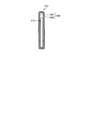
- FIG. 3 is a schematic diagram showing a schematic configuration of the receiving antenna shown in FIG.
- FIG. 4 is an enlarged view of the antenna unit of FIG.
- FIG. 5 is a partial sectional view taken along line AA in FIG.
- FIG. 6 is a partial cross-sectional view schematically showing the configuration of the main part of the antenna holder according to Modification 1 of Embodiment 1 of the present invention.
- FIG. 1 is a schematic diagram showing a schematic configuration of a capsule endoscope system including an antenna holder according to Embodiment 1 of the present invention.
- FIG. 2 is a schematic diagram illustrating a schematic configuration of the antenna holder illustrated in FIG. 1.
- FIG. 3 is a schematic diagram showing a schematic configuration of the receiving antenna shown
- FIG. 7 is a partial cross-sectional view schematically showing the configuration of the main part of the antenna holder according to Modification 2 of Embodiment 1 of the present invention.
- FIG. 8 is a diagram schematically illustrating a configuration of a main part of the antenna holder according to the third modification of the first embodiment of the present invention.
- FIG. 9 is a schematic diagram showing a configuration of an antenna holder according to Embodiment 2 of the present invention.
- 10 is a partial cross-sectional view taken along line BB of FIG.
- FIG. 11 is a partial cross-sectional view schematically showing the configuration of the main part of the antenna holder according to Modification 1 of Embodiment 2 of the present invention.
- FIG. 12 is a partial cross-sectional view schematically showing the configuration of the main part of the antenna holder according to the second modification of the second embodiment of the present invention.
- FIG. 13 is a diagram schematically showing the configuration of the main part of the antenna holder according to Modification 3 of Embodiment 2 of the present invention.
- FIG. 14 is a schematic diagram showing a schematic configuration of an antenna holder according to Embodiment 3 of the present invention.
- FIG. 15 is a partial cross-sectional view schematically showing the configuration of the antenna holder according to Embodiment 3 of the present invention.
- FIG. 16 is a partial cross-sectional view schematically showing the configuration of the main part of the antenna holder according to Modification 1 of Embodiment 3 of the present invention.
- FIG. 17 is a partial cross-sectional view schematically showing a configuration of a main part of an antenna holder according to Modification 2 of Embodiment 3 of the present invention.
- FIG. 18 is a schematic diagram showing a schematic configuration of an antenna holder according to Embodiment 4 of the present invention.
- 19 is a partial cross-sectional view taken along the line CC of FIG.
- FIG. 20 is a partial cross-sectional view schematically showing the configuration of the main part of the antenna holder according to Modification 1 of Embodiment 4 of the present invention.
- FIG. 21 is a partial cross-sectional view schematically showing a configuration of a main part of an antenna holder according to Modification 2 of Embodiment 4 of the present invention.
- FIG. 1 is a schematic diagram showing a schematic configuration of a capsule endoscope system including an antenna holder according to Embodiment 1 of the present invention.
- a capsule endoscope system 1 shown in FIG. 1 includes a capsule endoscope device 3 as a medical device introduced into a subject 2, and an antenna holder that is attached to the subject 2 and holds a plurality of receiving antennas.
- an antenna device 5 which is attached to the antenna holder 4 and has a plurality of receiving antennas for receiving radio signals transmitted from the capsule endoscope device 3 introduced into the subject 2, and the antenna device 5 Are detachably connected to the receiving device 6 that records and displays the radio signal received by the antenna device 5 by performing predetermined processing, and the image data in the subject 2 imaged by the capsule endoscope device 3.
- An antenna unit is configured by the antenna holder 4 and the reception antenna provided in the antenna device 5.
- the capsule endoscope apparatus 3 has an imaging function for imaging the inside of the subject 2 and a wireless function for transmitting a radio signal including image data obtained by imaging the inside of the subject 2 to the receiving antenna 51. .
- the capsule endoscope apparatus 3 passes through the esophagus in the subject 2 by being swallowed into the subject 2, and moves in the subject 2 by peristaltic movement of the digestive tract cavity.
- the capsule endoscope apparatus 3 sequentially images the inside of the subject 2 at a minute time interval, for example, 0.5 second interval (for example, 2 fps) while moving in the subject 2, and the image in the subject 2 is taken. Data is generated and sequentially transmitted to the antenna device 5.
- the capsule endoscope apparatus 3 outputs a radio signal having a frequency of 300 MHz to 450 MHz, for example.
- FIG. 2 is a schematic diagram showing a schematic configuration of the antenna holder shown in FIG. 1 and shows a state in which the antenna holder 4 is mounted on the subject 2.
- the antenna holder 4 includes a belt portion 41 that fixes the antenna holder 4 to the subject 2, an antenna attachment portion 42 that is supported by the belt portion 41 and to which a plurality of receiving antennas 51 are attached. Is provided.
- FIG. 3 is a schematic diagram showing a schematic configuration of the receiving apparatus shown in FIG.
- the antenna device 5 includes a plurality of receiving antennas 51 that receive wireless signals from the capsule endoscope device 3, and an antenna cable that propagates the wireless signals received by the plurality of receiving antennas 51 to the receiving device 6. 52 and a connector portion 53 connected to the receiving device 6.
- the receiving antenna 51 includes an antenna pattern 511 as a receiving unit that receives a radio signal from the capsule endoscope apparatus 3, and a substrate member 512 on which a wiring pattern is formed.
- the wiring pattern formed on the substrate member 512 outputs a radio signal received by the antenna pattern 511 to the receiving device 6.
- the substrate member 512 may be configured using a flexible substrate that can be bent, or may be configured using a rigid substrate having rigidity.
- the belt portion 41 of the antenna holder 4 is attached to the subject 2 to fix the antenna holder 4 along the body surface of the subject 2.
- the belt portion 41 is preferably formed using a stretchable material such as rubber or polyurethane elastic fiber so that the antenna holder 4 can be fixed according to the physique of the subject.
- FIG. 4 is an enlarged view of the antenna mounting portion 42 of FIG.
- FIG. 5 is a partial cross-sectional view taken along line AA of the antenna mounting portion 42 shown in FIG.
- the subject 2 is disposed on the left side of the antenna mounting portion 42.
- the antenna mounting portion 42 is provided in the main body portion 421 that houses the plurality of receiving antennas 51 and the shield member 54, and each holds one receiving antenna 51.
- the antenna fixing portions 422 for fixing the position.
- the number of antenna fixing units 422 is six and six receiving antennas 51 are attached.
- the number of antenna fixing units 422 and receiving antennas 51 is not limited to six. Further, the number of the antenna fixing units 422 and the receiving antennas 51 is not necessarily the same.
- the main body 421 has a bag shape formed using cloth or the like.
- the main body 421 has an openable and closable opening formed using, for example, a point fastener, a wire fastener, or a hook-and-loop fastener.
- the antenna fixing portion 422 is formed of a pocket-shaped cloth or the like, and accommodates one receiving antenna 51 therein. Each antenna fixing part 422 is provided corresponding to the position where the receiving antenna 51 is arranged.
- the shield member 54 reduces the passage of electromagnetic waves.
- “reduction of electromagnetic waves” includes complete shielding that does not transmit electromagnetic waves completely.
- the shield member 54 is produced, for example, by braiding conductive fibers into a mesh shape.
- the shield member 54 may be formed using an electromagnetic shielding material in addition to the conductive fiber.
- the shield member 54 may be a conductive metal plate, sheet, or non-woven cloth.
- the shield member 54 may reduce electromagnetic waves in a specific frequency band.
- the shield member 54 may be subjected to at least one of corrosion prevention processing and water resistance processing.
- corrosion prevention processing for example, a surface treatment is performed to prevent rust.
- water-resistant processing a treatment that prevents the conductive fibers from touching water is performed by a surface treatment such as coating. Since the shield member 54 is subjected to corrosion prevention processing and water resistance processing, the main body portion 421 can be washed with water even while the shield member 54 remains in the main body portion 421. At this time, the receiving antenna 51 is removed.
- the shield member 54 has a size that can cover one surface of the substrate members 512 of all the receiving antennas 51 when accommodated in the main body 421.
- the shield member 54 is larger in size than the surface where the shield member 54 covers the substrate member 512.
- the shield member 54 may be larger than the surface covering the substrate member 512.
- the “size that can be covered” refers to a size that is greater than or equal to the size of the surface to be covered.
- the shield member 54 has a size that includes the substrate member 512 in the projection region when the surface of the shield member 54 is projected onto the substrate member 512.
- the shield member 54 When the antenna holder 4 is attached to the subject 2, the shield member 54 is disposed on the opposite side of the subject 2 with respect to the receiving antenna 51. That is, the shield member 54 covers the surface of each receiving antenna 51 opposite to the subject 2 side. In a state where the antenna holder 4 is mounted on the subject 2, the portion of the main body 421 that is attached to the subject 2, the receiving antenna 51, the shield member 54, and the subject 2 of the main body 421 in order from the subject 2 side. A portion opposite to the side to be attached to is disposed.
- the receiving device 6 records the image data in the subject 2 included in the wireless signal transmitted from the capsule endoscope device 3 via the plurality of receiving antennas 51 or corresponds to the image data in the subject 2. Display an image.
- the reception device 6 includes a reception display unit 61 that displays an image corresponding to the image data, and an operation unit 62 that receives an input of an instruction signal for operating the reception device 6 and information regarding the position of each reception antenna 51. .
- the receiving device 6 receives the radio signal transmitted from the capsule endoscope device 3 via each receiving antenna 51, and the reception antenna 51 receives the reception intensity (reception electric field strength) of the received radio signal. While calculating and recording every time, the position of the capsule endoscope apparatus 3 in the subject 2 is estimated.
- the receiving device 6 includes image data included in the wireless signal received from the capsule endoscope device 3, reception intensity of the wireless signal received by each receiving antenna 51, and image data generated by the capsule endoscope device 3. Are recorded in association with each other.
- the image processing device 7 displays an image corresponding to the image data in the subject 2 acquired via the receiving device 6.
- the image processing device 7 includes a cradle 71 that reads image data and the like from the receiving device 6, an operation input unit 72 such as a mouse 72a and a keyboard 72b, and a display unit 73 that displays an image corresponding to the image data.
- the cradle 71 receives image data from the receiving device 6, reception intensity of each receiving antenna 51 associated with the image data, and time of image data generated by the capsule endoscope device 3.
- Information and identification information of the capsule endoscope apparatus 3 are acquired, and the acquired various information is transferred to the image processing apparatus 7.
- the operation input unit 72 receives input from the user.
- the user While operating the operation input unit 72, the user observes a living body part inside the subject 2, such as the esophagus, stomach, small intestine, large intestine, and the like, while sequentially viewing images in the subject 2 displayed by the image processing apparatus 7.
- the subject 2 is diagnosed.
- each antenna fixing portion 422 holds the plurality of receiving antennas 51, and shield members so as to cover one surface of the substrate members 512 of all the receiving antennas 51. 54 was held.
- the surface of the receiving antenna 51 opposite to the subject 2 is shielded by the shield member 54, and is necessary as compared with the amount of fiber required for the protective clothing in order to reduce noise from the outside.
- the deterioration of communication quality can be suppressed while suppressing the amount of material.
- Even when the shield member 54 is made of a material different from fibers, such as a metal plate, the shield area is smaller than the shield area by the protective clothing, so the amount of the material is equivalent to the protective clothing. It can be suppressed compared with the amount of material.
- the shield member 54 can be produced with a small amount of fibers compared to the amount of fibers required for production of protective clothing, it is possible to reduce the manufacturing and distribution costs compared to the case of using protective clothing.
- FIG. 6 is a partial cross-sectional view schematically showing the configuration of the main part of the antenna holder according to Modification 1 of Embodiment 1 of the present invention.
- the partial cross-sectional view shown in FIG. 6 corresponds to the cross section along line AA shown in FIG.
- the shield member 54 has been described as being housed in the main body 421. However, in the first modification, the shield member 54 is provided outside the main body 421.
- the antenna holder according to the first modification includes the above-described belt portion 41 and the antenna attachment portion 42A.
- the antenna attachment portion 42A includes the main body portion 421 described above and six antenna fixing portions 422 that are provided in the main body portion 421 and each hold one receiving antenna 51 and fix its position.
- the shield member 54 is attached to the outer surface of the main body 421 and to the outer surface opposite to the subject 2 side when the antenna holder is attached to the subject 2.
- the shield member 54 is attached to the main body 421 by a known fixing means such as an adhesive or a button.
- the shield member 54 is arranged.
- the plurality of antenna fixing portions 422 hold the plurality of reception antennas 51 and the shield member 54 is provided so as to cover one surface of the substrate members 512 of all the reception antennas 51.
- the surface opposite to the subject 2 side of the antenna 51 is shielded by the shield member 54, and deterioration of communication quality can be suppressed with a simple configuration while suppressing the amount of material required.
- FIG. 7 is a partial cross-sectional view schematically showing the configuration of the main part of the antenna holder according to Modification 2 of Embodiment 1 of the present invention.
- the partial cross-sectional view shown in FIG. 7 corresponds to the cross section along line AA shown in FIG.
- the shield member 54 has been described as being separate from the main body 421.
- the shield member forms part of the main body.
- the antenna holder according to the second modification includes the above-described belt portion 41 and the antenna attachment portion 42B.
- the antenna attachment portion 42B includes a main body portion 421A that accommodates a plurality of reception antennas 51, and six antenna fixing portions 422 that are provided in the main body portion 421, each holding one reception antenna 51 and fixing its position. Have.
- the main body 421A has a bag shape.
- the main body portion 421A includes a partial main body portion 4211 that forms a part of a bag shape and is provided with an antenna fixing portion 422, and a shield portion 4212 that reduces the passage of electromagnetic waves and forms a bag shape together with the partial main body portion 4211.
- the partial main body 4211 is arranged on the subject 2 side.
- the shield part 4212 is formed using, for example, conductive fibers, similarly to the shield member 54 described above.
- the shield part 4212 is located on the surface opposite to the subject 2 side of the receiving antenna 51 and covers the surface opposite to the subject 2 side of the substrate members 512 of all the receiving antennas 51. Yes.
- the shield part 4212 corresponds to a shield member.
- a partial main body portion 4211 that is a portion attached to the subject 2 of the main body portion 421 A in order from the subject 2 side, the receiving antenna 51, A shield part 4212 common to the part of the main body part 421A opposite to the side attached to the subject 2 is arranged.
- the plurality of antenna fixing portions 422 hold the plurality of receiving antennas 51 and the shield portion 4212 is provided so as to cover one surface of the substrate member 512 of all the receiving antennas 51.
- the surface of the antenna 51 opposite to the subject 2 side is shielded by the shield part 4212, and the deterioration of communication quality can be suppressed with a simple configuration while suppressing the amount of material required.
- FIG. 8 is a diagram schematically illustrating a configuration of a main part of the antenna holder according to the third modification of the first embodiment of the present invention.
- each antenna fixing portion 422 is described as holding one receiving antenna 51.
- the antenna mounting portion 42C according to Modification 3 is provided with two antenna fixing portions 422a.
- Each antenna fixing portion 422a accommodates a plurality (three in FIG. 8) of receiving antennas 51. Even in such a configuration, the above-described effects can be obtained by providing the shield member 54.
- each antenna fixing portion 422a accommodates different receiving antennas 51.
- FIG. 9 is a schematic diagram showing a configuration of an antenna holder according to Embodiment 2 of the present invention.
- FIG. 10 is a partial cross-sectional view taken along line BB of the antenna mounting portion shown in FIG.
- one shield member 54 has been described as collectively covering a plurality of reception antennas 51.
- the plurality of shield members 54A individually receive the reception antennas 51. Cover each one.
- the antenna holder according to the second embodiment includes the belt portion 41 and the antenna attachment portion 42D described above. As shown in FIGS. 9 and 10, the antenna attachment portion 42 ⁇ / b> D is provided in the main body portion 421 ⁇ / b> B that accommodates the plurality of receiving antennas 51 and the plurality of shield members 54 ⁇ / b> A, and each receiving antenna 51. And six antenna fixing portions 425 for holding the shield member 54A and fixing the position thereof.
- the main body 421B has a bag shape formed using a cloth or the like.
- the main body 421B has an openable and closable opening formed using, for example, a point fastener, a line fastener, or a hook-and-loop fastener.
- the antenna fixing part 425 is a cloth or the like formed in a pocket shape, and accommodates one receiving antenna 51 and one shield member 54A therein. Each antenna fixing portion 425 is provided corresponding to the arrangement of the receiving antenna 51.
- the shield member 54A has a mesh shape formed using conductive fibers.
- the shield member 54A is formed using the same material as the shield member 54 described above.
- the shield member 54 ⁇ / b> A has a size that can cover the substrate member 512 of the receiving antenna 51.
- the shield member 54 ⁇ / b> A has a size capable of covering one surface of the substrate member 512 of the receiving antenna 51 accommodated in the same antenna fixing portion 425 when accommodated in the antenna fixing portion 425.
- the shield member 54 ⁇ / b> A is disposed on the opposite side of the subject 2 with respect to the receiving antenna 51. That is, each shield member 54A covers the surface of each receiving antenna 51 opposite to the subject 2 side.
- the plurality of antenna fixing portions 425 accommodate the plurality of reception antennas 51 and the plurality of shield members 54A, respectively, and each shield member 54A is one of the substrate members 512 of each reception antenna 51. Each side was covered. According to the second embodiment, the surface of the receiving antenna 51 opposite to the subject 2 side is shielded by the shield member 54A to reduce noise from the outside. Communication quality deterioration can be suppressed with a simple configuration.
- the discomfort of the subject due to the close contact of the protective clothing is reduced, and compared with the case where the protective clothing is used.
- distribution costs can be reduced.
- the shield member 54A may be attached to the outer surface of the pocket formed by the antenna fixing portion 425.
- FIG. 11 is a partial cross-sectional view schematically showing the configuration of the main part of the antenna holder according to Modification 1 of Embodiment 2 of the present invention.
- the partial cross-sectional view shown in FIG. 11 corresponds to the cross section taken along line BB shown in FIG.
- each shield member 54A has been described as being housed in the main body 421B.
- the shield member 54A is provided outside the main body 421B.
- the antenna holder according to the first modification includes the above-described belt portion 41 and the antenna attachment portion 42E.
- the antenna attachment portion 42E includes the main body portion 421 described above and six antenna fixing portions 422 that are provided in the main body portion 421 and each hold one receiving antenna 51 and fix its position.
- Each shield member 54A is attached to the outer surface of the main body 421, which is the outer surface opposite to the subject side when the antenna holder is attached to the subject 2, according to the arrangement of the receiving antenna 51. .
- Each shield member 54A is attached to the main body 421 by a known fixing means such as an adhesive or a button.
- the plurality of antenna fixing portions 422 hold the plurality of reception antennas 51 and a plurality of shields so as to cover the surface of each reception antenna 51 (substrate member 512) opposite to the subject 2 side. Since the member 54A is provided, the surface opposite to the subject 2 side of the receiving antenna 51 is shielded by the shield member 54A, and the deterioration of communication quality is suppressed with a simple configuration while suppressing the amount of material required. Can do.
- FIG. 12 is a partial cross-sectional view schematically showing the configuration of the main part of the antenna holder according to the second modification of the second embodiment of the present invention.
- the partial cross-sectional view shown in FIG. 12 corresponds to the cross section taken along line BB shown in FIG.
- the shield member 54A has been described as being separate from the antenna fixing portion 425.
- the shield member is provided as the antenna fixing portion.
- the antenna holder according to the second modification includes the belt portion 41 and the antenna attachment portion 42F described above.
- the antenna attachment portion 42F includes the main body portion 421 described above and six shield members 54B that are provided in the main body portion 421 and each hold one receiving antenna 51 and fix its position.
- the shield member 54B is formed in a pocket shape using conductive fibers and accommodates one receiving antenna 51 therein.
- the shield member 54B has a function of an antenna fixing unit that fixes the reception antenna 51 and a shield function that shields the surface of the reception antenna 51 opposite to the subject 2 side.
- the shield member 54B is preferably subjected to corrosion prevention processing and water resistance processing.
- the portion corresponding to the lower surface of the pocket may be formed of cloth, and only the portion of the receiving antenna 51 facing the surface opposite to the subject 2 may be formed of conductive fibers or the like.
- the plurality of shield members 54B detachably hold the plurality of reception antennas 51, thereby shielding the surface of each reception antenna 51 (substrate member 512) opposite to the subject 2 side. Since it did in this way, deterioration of communication quality can be suppressed with a simple structure, suppressing the amount of required materials.
- FIG. 13 is a diagram schematically showing the configuration of the main part of the antenna holder according to Modification 3 of Embodiment 2 of the present invention.
- each antenna fixing portion 425 has been described as holding one receiving antenna 51.
- the antenna mounting portion 42G according to Modification 3 is provided with two antenna fixing portions 422a.
- Each antenna fixing portion 422a accommodates a plurality (three in FIG. 13) of receiving antennas 51.
- the third modification includes two shield members 54 ⁇ / b> C provided in each antenna fixing portion 422 a.
- Each shield member 54 ⁇ / b> C covers different receiving antennas 51.
- the shield member 54C according to the third modification has a size that can cover the substrate members 512 of the three receiving antennas 51 held by the antenna fixing portion 422a. Even in the configuration of the third modification, the above-described effects can be obtained by the arrangement of the shield member 54.
- FIG. 14 is a schematic diagram showing the configuration of the antenna holder according to Embodiment 3 of the present invention, and shows a state in which the antenna holder is attached to the subject 2.
- FIG. 15 is a partial cross-sectional view of the antenna holder, and is a partial cross-sectional view in which a plane orthogonal to a surface attached to the subject 2 (for example, a surface facing the subject 2 in the substrate member 512) is a cut surface.
- the capsule endoscope system includes a capsule endoscope apparatus 3, a plurality of antenna holders 40A that are mounted on the subject 2 and hold a plurality of receiving antennas 51, and each antenna holder. 40A, the antenna device 5 having a plurality of receiving antennas 51 for receiving radio signals transmitted from the capsule endoscope device 3 introduced into the subject 2, the receiving device 6, and image processing And a device 7 (see FIG. 1).
- the antenna holder 40 ⁇ / b> A is composed of a main body 426 having a bag shape formed using a cloth or the like.
- the main body 426 accommodates one receiving antenna 51 and one shield member 54A.
- the plurality of antenna holders 40 ⁇ / b> A are independent from each other and are respectively attached to predetermined positions of the subject 2.
- the shield member 54A has a size capable of covering one surface of the receiving antenna 51 accommodated in the same antenna holder 40A when accommodated in the antenna holder 40A.
- the shield member 54A is disposed on the opposite side of the subject 2 with respect to the receiving antenna 51. That is, each shield member 54A covers the surface of each receiving antenna 51 opposite to the subject 2 side.
- the plurality of antenna holders 40A accommodate the plurality of reception antennas 51 and the plurality of shield members 54A, respectively, and each shield member 54A is one surface of the substrate member 512 of each reception antenna 51. Each was covered. According to the third embodiment, the surface of the receiving antenna 51 opposite to the subject 2 side is shielded by the shield member 54A to reduce noise from the outside. Quality deterioration can be suppressed.
- the discomfort of the subject due to close contact of the protective clothing is reduced, and compared with the case where the protective clothing is used.
- distribution costs can be reduced.
- FIG. 16 is a partial cross-sectional view schematically showing the configuration of the main part of the antenna holder according to Modification 1 of Embodiment 3 of the present invention.
- each shield member 54A has been described as being housed in the antenna holder 40A.
- the shield member 54A is provided outside the antenna holder 40B.
- the receiving antenna 51 is accommodated, and the shield member 54A is attached to the outer surface opposite to the subject side when the subject 2 is attached to the antenna holder.
- Each shield member 54A is attached to the main body 426 by a known fixing means such as an adhesive or a button.
- the plurality of antenna holders 40B hold the plurality of reception antennas 51, respectively, and the plurality of shields so as to cover the surface of the reception antenna 51 opposite to the subject side on the outer surface of the antenna holder 40B. Since the member 54A is provided, the surface of the reception antenna 51 (substrate member 512) opposite to the subject 2 is shielded by the shield member 54A, and the deterioration of communication quality is suppressed while suppressing the amount of necessary material. be able to.
- FIG. 17 is a partial cross-sectional view schematically showing a configuration of a main part of an antenna holder according to Modification 2 of Embodiment 3 of the present invention.
- the shield member 54A has been described as being separate from the antenna holder 40A.
- the shield member is provided as the main body.
- the antenna holder 40 ⁇ / b> C according to the second modification has a main body portion 427 that accommodates the reception antenna 51.
- the main body 427 has a bag shape.
- the main body portion 427 is formed using a cloth or the like, and includes a partial main body portion 4271 that forms a part of a bag shape, and a shield portion 4272 that reduces electromagnetic waves and forms a bag shape together with the partial main body portion 4271.
- the main body 427 has the partial main body 4271 disposed on the subject 2 side when the antenna holder 40 ⁇ / b> C is attached to the subject 2.
- the shield part 4272 is formed using, for example, conductive fibers, in the same manner as the shield member 54 described above.
- the shield portion 4272 is located on the surface opposite to the subject 2 side of the receiving antenna 51, and covers the surface opposite to the subject 2 side of all the receiving antennas 51 (substrate member 512). ing.
- the shield part 4272 corresponds to a shield member.
- the plurality of antenna holders 40C respectively hold the plurality of reception antennas 51 and the shield portion 4272 is provided so as to cover the surface of the reception antenna 51 opposite to the subject side.
- the surface of 51 opposite to the subject 2 side is shielded by the shield part 4272, and the deterioration of communication quality can be suppressed while suppressing the amount of material required.
- FIG. 18 is a schematic diagram showing the configuration of the antenna holder according to Embodiment 4 of the present invention, and shows a state where the antenna holder is attached to the subject 2.
- FIG. 19 is a partial cross-sectional view taken along line CC of the antenna mounting portion shown in FIG.
- the capsule endoscope system according to the fourth embodiment includes a capsule endoscope apparatus 3, an antenna holder 4A that is mounted on the subject 2 and holds a substrate member 513 on which a plurality of antenna patterns 511 are formed.
- the antenna device 5A is attached to the antenna holder 4A and includes a substrate member 513, a receiving device 6, and an image processing device 7 (see FIG. 1).
- the antenna holder 4A includes the belt portion 41 and the antenna attachment portion 42H described above.
- the antenna attachment portion 42H includes a substrate member 513 on which a plurality of reception antennas 51 are formed, and a main body portion 428 that accommodates the shield member 54D.
- the antenna device 5A has an antenna cable 52 and a connector portion 53, and a substrate member 513 instead of the plurality of reception antennas 51 described above.
- the board member 513 includes a plurality of antenna patterns 511 that receive radio signals from the capsule endoscope apparatus 3 and transmission patterns (not shown) for transmitting electric signals from the antenna patterns 511 to the antenna cable 52. ) And are formed.
- the capsule endoscope apparatus 3 since the arrangement of the antenna pattern 511 on the board member 513 is determined in advance, the capsule endoscope apparatus 3 is based on the radio signal acquired by itself and the arrangement of the board member 513 with respect to the subject 2. Position detection can be performed.
- the main body 428 has a bag shape formed using cloth or the like.
- the main body 428 houses the substrate member 513 and the shield member 54D.
- the main body 428 has an openable and closable opening formed using, for example, a point fastener, a line fastener, or a hook-and-loop fastener.
- the shield member 54D has a size that can cover all the antenna patterns 511 formed on the substrate member 513 when accommodated in the main body 428.
- the shield member 54D according to the fourth embodiment has a size capable of covering the substrate member 513.
- the shield member 54D is disposed on the opposite side of the subject 2 with respect to the substrate member 513. That is, the shield member 54D covers all the antenna patterns 511 by covering the surface of the substrate member 513 opposite to the subject 2 side.
- the main body 428 accommodates the substrate member 513 on which the plurality of antenna patterns 511 are formed and the shield member 54D, and the shield member 54D is opposite to the subject side of the substrate member 513.
- the side surface was covered.
- the antenna pattern 511 formed on the board member 513 is shielded to reduce noise from the outside, and thus the deterioration of communication quality is suppressed while suppressing the amount of necessary material. be able to.
- the discomfort of the subject due to the close contact of the protective clothing is reduced, and compared with the case where the protective clothing is used.
- distribution costs can be reduced.
- FIG. 20 is a partial cross-sectional view schematically showing the configuration of the main part of the antenna holder according to Modification 1 of Embodiment 4 of the present invention.
- the shield member 54D has been described as being housed in the main body 428.
- the shield member 54D is provided outside the main body 428.
- the antenna holder according to the first modification includes the belt portion 41 and the antenna attachment portion 42I described above.
- the antenna attachment portion 42I accommodates the reception antenna 51 and has a main body portion 428 to which a shield member 54D is attached on the outer surface opposite to the subject side when the subject 2 is attached to the antenna holder.
- the shield member 54D is attached to the main body 428 by a known fixing means such as an adhesive or a button.
- the main body 428 holds the substrate member 513 on which the plurality of antenna patterns 511 are formed, and covers the surface of the substrate member 513 opposite to the subject side on the outer surface of the main body 428. Since the shield member 54D is provided, the antenna patterns 511 are shielded by the shield member 54D, and the deterioration of communication quality can be suppressed while suppressing the amount of material required.
- FIG. 21 is a partial cross-sectional view schematically showing a configuration of an antenna holder according to Modification 2 of Embodiment 4 of the present invention.
- the shield member 54D has been described as being separate from the main body 428.
- the shield member forms part of the main body.
- the antenna attachment portion 42J according to the second modification includes a main body portion 429 that accommodates the board member 513.
- the main body 429 has a bag shape.
- the main body portion 429 is formed using a cloth or the like, has a partial main body portion 4291 that forms part of a bag shape, and a mesh shape formed using conductive fibers, and forms a bag shape together with the partial main body portion 4291.
- a shield part 4292 that has In the main body 429, the partial main body 4291 is arranged on the subject 2 side when the antenna holder is attached to the subject 2.
- the shield part 4292 is located on the surface of the receiving antenna 51 opposite to the subject 2 side and covers the surface of all the receiving antennas 51 opposite to the subject 2 side.
- the shield part 4292 corresponds to a shield member.
- the main body portion 429 holds the substrate member 513 on which the plurality of antenna patterns 511 are formed, and the shield portion 4292 forms an outer surface opposite to the subject side of the main body portion 429. Since the surface of the substrate member 513 opposite to the subject side is covered, the surface of the substrate member 513 opposite to the subject 2 side is shielded, and the communication quality is reduced while suppressing the required amount of material. Deterioration can be suppressed.
- the shield member is described as covering the substrate member on which the antenna pattern is formed. However, if the shield member covers at least the region where the antenna pattern is formed, the effect can be obtained. Obtainable. For this reason, the shield member can be applied as long as at least a portion corresponding to the antenna pattern formation region can obtain a shielding effect with conductive fibers or the like.
- the capsule endoscope apparatus 3 has been described as an example of the medical apparatus, but the medical apparatus is not limited to this.
- the medical apparatus may be a device that is introduced into a subject, acquires pH information, and outputs it as a radio signal.
- the antenna holder and the antenna unit according to the present invention are useful for suppressing deterioration of communication quality while suppressing the amount of necessary material.
- Capsule-type endoscope system 2 Subject 3 Capsule-type endoscope apparatus 4, 4A, 40A, 40B, 40C Antenna holder 41 Belt part 42, 42A, 42B, 42C, 42D, 42E, 42F, 42G, 42H, 42I , 42J Antenna mounting portion 5 Antenna device 6 Reception device 7 Image processing device 51 Reception antenna 52 Antenna cable 53 Connector portion 54, 54A, 54C, 54D Shield member 54B, 4212, 4272, 4292 Shield portion 61 Reception display portion 62 Operation portion 71 Cradle 72 Operation input unit 72a Mouse 72b Keyboard 73 Display unit
Landscapes
- Life Sciences & Earth Sciences (AREA)
- Health & Medical Sciences (AREA)
- Surgery (AREA)
- Engineering & Computer Science (AREA)
- Heart & Thoracic Surgery (AREA)
- Medical Informatics (AREA)
- Nuclear Medicine, Radiotherapy & Molecular Imaging (AREA)
- Optics & Photonics (AREA)
- Pathology (AREA)
- Radiology & Medical Imaging (AREA)
- Physics & Mathematics (AREA)
- Biomedical Technology (AREA)
- Veterinary Medicine (AREA)
- Biophysics (AREA)
- Molecular Biology (AREA)
- Animal Behavior & Ethology (AREA)
- General Health & Medical Sciences (AREA)
- Public Health (AREA)
- Computer Networks & Wireless Communication (AREA)
- Microelectronics & Electronic Packaging (AREA)
- Endoscopes (AREA)
- Signal Processing (AREA)
- Variable-Direction Aerials And Aerial Arrays (AREA)
- Details Of Aerials (AREA)
Abstract
Le support d'antenne selon l'invention supporte une antenne de réception présentant au moins une unité de réception pour recevoir un signal sans fil transmis à partir d'un dispositif médical introduit dans un sujet et est pourvu d'un élément de blindage qui est disposé sur un côté opposé au côté du support d'antenne fixé au sujet et qui réduit les ondes électromagnétiques reçues par l'antenne de réception à partir du côté opposé au côté fixé au sujet.
Priority Applications (3)
| Application Number | Priority Date | Filing Date | Title |
|---|---|---|---|
| JP2018545505A JP6483335B1 (ja) | 2017-06-13 | 2018-04-19 | アンテナホルダ及びアンテナユニット |
| CN201880035653.XA CN110708998A (zh) | 2017-06-13 | 2018-04-19 | 天线支架及天线单元 |
| US16/683,865 US20200083597A1 (en) | 2017-06-13 | 2019-11-14 | Antenna holder and antenna unit |
Applications Claiming Priority (2)
| Application Number | Priority Date | Filing Date | Title |
|---|---|---|---|
| JP2017-116179 | 2017-06-13 | ||
| JP2017116179 | 2017-06-13 |
Related Child Applications (1)
| Application Number | Title | Priority Date | Filing Date |
|---|---|---|---|
| US16/683,865 Continuation US20200083597A1 (en) | 2017-06-13 | 2019-11-14 | Antenna holder and antenna unit |
Publications (1)
| Publication Number | Publication Date |
|---|---|
| WO2018230153A1 true WO2018230153A1 (fr) | 2018-12-20 |
Family
ID=64659151
Family Applications (1)
| Application Number | Title | Priority Date | Filing Date |
|---|---|---|---|
| PCT/JP2018/016203 WO2018230153A1 (fr) | 2017-06-13 | 2018-04-19 | Support d'antenne et unité d'antenne |
Country Status (4)
| Country | Link |
|---|---|
| US (1) | US20200083597A1 (fr) |
| JP (1) | JP6483335B1 (fr) |
| CN (1) | CN110708998A (fr) |
| WO (1) | WO2018230153A1 (fr) |
Cited By (2)
| Publication number | Priority date | Publication date | Assignee | Title |
|---|---|---|---|---|
| WO2021181701A1 (fr) * | 2020-03-13 | 2021-09-16 | オリンパス株式会社 | Support d'antenne |
| JP7429921B2 (ja) | 2020-05-08 | 2024-02-09 | 国立大学法人信州大学 | カプセル内視鏡位置検出装置 |
Citations (4)
| Publication number | Priority date | Publication date | Assignee | Title |
|---|---|---|---|---|
| JP2006078699A (ja) * | 2004-09-08 | 2006-03-23 | Olympus Corp | 表示装置 |
| JP2006075365A (ja) * | 2004-09-09 | 2006-03-23 | Olympus Corp | 受信装置および被検体内導入システム |
| WO2007074888A1 (fr) * | 2005-12-27 | 2007-07-05 | Olympus Corporation | Systeme de guidage de dispositif medical de type capsule et son procede de commande |
| JP2007307005A (ja) * | 2006-05-17 | 2007-11-29 | Pentax Corp | 2次元拡散通信用基板及び通信装置 |
Family Cites Families (7)
| Publication number | Priority date | Publication date | Assignee | Title |
|---|---|---|---|---|
| JP4409258B2 (ja) * | 2003-11-20 | 2010-02-03 | オリンパス株式会社 | カプセル型内視鏡およびその製造方法 |
| JP2005245938A (ja) * | 2004-03-08 | 2005-09-15 | Pentax Corp | 診断用着衣、診断用着衣システム、及び内視鏡システム |
| WO2012165426A1 (fr) * | 2011-05-30 | 2012-12-06 | オリンパスメディカルシステムズ株式会社 | Dispositif d'antenne, antenne et support d'antennes |
| CN202821355U (zh) * | 2012-08-31 | 2013-03-27 | 安翰光电技术(武汉)有限公司 | 一种可控胶囊内窥镜定位天线功能服 |
| EP3178368A1 (fr) * | 2014-08-07 | 2017-06-14 | Olympus Corporation | Support d'antenne, dispositif d'antenne, et système d'inspection |
| JP2016182215A (ja) * | 2015-03-25 | 2016-10-20 | メディカル・エイド株式会社 | カプセル内視鏡用電磁波防護服及びその製造方法 |
| CN204794287U (zh) * | 2015-06-02 | 2015-11-18 | 介面光电股份有限公司 | 吊挂式可挠无线充电装置 |
-
2018
- 2018-04-19 WO PCT/JP2018/016203 patent/WO2018230153A1/fr active Application Filing
- 2018-04-19 JP JP2018545505A patent/JP6483335B1/ja active Active
- 2018-04-19 CN CN201880035653.XA patent/CN110708998A/zh active Pending
-
2019
- 2019-11-14 US US16/683,865 patent/US20200083597A1/en not_active Abandoned
Patent Citations (5)
| Publication number | Priority date | Publication date | Assignee | Title |
|---|---|---|---|---|
| JP2006078699A (ja) * | 2004-09-08 | 2006-03-23 | Olympus Corp | 表示装置 |
| JP2006075365A (ja) * | 2004-09-09 | 2006-03-23 | Olympus Corp | 受信装置および被検体内導入システム |
| WO2007074888A1 (fr) * | 2005-12-27 | 2007-07-05 | Olympus Corporation | Systeme de guidage de dispositif medical de type capsule et son procede de commande |
| WO2007077896A1 (fr) * | 2005-12-27 | 2007-07-12 | Olympus Medical Systems Corp. | Systeme de guidage d’un dispositif medical encapsule et son procede de commande |
| JP2007307005A (ja) * | 2006-05-17 | 2007-11-29 | Pentax Corp | 2次元拡散通信用基板及び通信装置 |
Cited By (2)
| Publication number | Priority date | Publication date | Assignee | Title |
|---|---|---|---|---|
| WO2021181701A1 (fr) * | 2020-03-13 | 2021-09-16 | オリンパス株式会社 | Support d'antenne |
| JP7429921B2 (ja) | 2020-05-08 | 2024-02-09 | 国立大学法人信州大学 | カプセル内視鏡位置検出装置 |
Also Published As
| Publication number | Publication date |
|---|---|
| CN110708998A (zh) | 2020-01-17 |
| US20200083597A1 (en) | 2020-03-12 |
| JPWO2018230153A1 (ja) | 2019-06-27 |
| JP6483335B1 (ja) | 2019-03-13 |
Similar Documents
| Publication | Publication Date | Title |
|---|---|---|
| JP6483335B1 (ja) | アンテナホルダ及びアンテナユニット | |
| JP4610975B2 (ja) | 表示装置 | |
| JP2005198789A (ja) | カプセル型内視鏡装置 | |
| JP2007130263A (ja) | 生体内画像取得装置 | |
| KR101045746B1 (ko) | 수신 시스템 | |
| JP2007143648A (ja) | 生体内画像表示装置 | |
| JP5525780B2 (ja) | 電子内視鏡装置 | |
| EP2399522B1 (fr) | Système de surveillance | |
| EP1922978A1 (fr) | Dispositif à introduire dans un sujet | |
| US20210091451A1 (en) | Receiving antenna system and capsule endoscope system | |
| JP5948523B1 (ja) | アンテナホルダー、アンテナ装置、及び検査システム | |
| US20190387957A1 (en) | Antenna holder and antenna attachment portion | |
| JP5548324B1 (ja) | 基板構造 | |
| JP5490328B1 (ja) | 電子内視鏡装置 | |
| JP2008237842A (ja) | 超音波内視鏡 | |
| JP6392038B2 (ja) | アンテナ装置 | |
| US20210401269A1 (en) | Antenna holder and capsule endoscope system | |
| JP4624815B2 (ja) | 受信装置 | |
| JP2007190067A (ja) | ワイヤレス超音波診断装置 | |
| JP4398203B2 (ja) | 無線型被検体内情報取得装置の保護装置 | |
| WO2021181701A1 (fr) | Support d'antenne | |
| WO2020246006A1 (fr) | Dispositif d'antenne et système d'antenne | |
| JP3965176B2 (ja) | 内視鏡形状検出装置 | |
| JP2005342436A (ja) | 医療機器用収納ベルト | |
| JP2005342438A (ja) | 医療機器用収納ベルト |
Legal Events
| Date | Code | Title | Description |
|---|---|---|---|
| ENP | Entry into the national phase |
Ref document number: 2018545505 Country of ref document: JP Kind code of ref document: A |
|
| 121 | Ep: the epo has been informed by wipo that ep was designated in this application |
Ref document number: 18817986 Country of ref document: EP Kind code of ref document: A1 |
|
| NENP | Non-entry into the national phase |
Ref country code: DE |
|
| 122 | Ep: pct application non-entry in european phase |
Ref document number: 18817986 Country of ref document: EP Kind code of ref document: A1 |