WO2018229838A1 - 極端紫外光センサユニット及び極端紫外光生成装置 - Google Patents
極端紫外光センサユニット及び極端紫外光生成装置 Download PDFInfo
- Publication number
- WO2018229838A1 WO2018229838A1 PCT/JP2017/021678 JP2017021678W WO2018229838A1 WO 2018229838 A1 WO2018229838 A1 WO 2018229838A1 JP 2017021678 W JP2017021678 W JP 2017021678W WO 2018229838 A1 WO2018229838 A1 WO 2018229838A1
- Authority
- WO
- WIPO (PCT)
- Prior art keywords
- ultraviolet light
- extreme ultraviolet
- purge gas
- light sensor
- sensor unit
- Prior art date
- Legal status (The legal status is an assumption and is not a legal conclusion. Google has not performed a legal analysis and makes no representation as to the accuracy of the status listed.)
- Ceased
Links
Images



Classifications
-
- H—ELECTRICITY
- H05—ELECTRIC TECHNIQUES NOT OTHERWISE PROVIDED FOR
- H05G—X-RAY TECHNIQUE
- H05G2/00—Apparatus or processes specially adapted for producing X-rays, not involving X-ray tubes, e.g. involving generation of a plasma
- H05G2/001—Production of X-ray radiation generated from plasma
- H05G2/009—Auxiliary arrangements not involved in the plasma generation
-
- G—PHYSICS
- G01—MEASURING; TESTING
- G01J—MEASUREMENT OF INTENSITY, VELOCITY, SPECTRAL CONTENT, POLARISATION, PHASE OR PULSE CHARACTERISTICS OF INFRARED, VISIBLE OR ULTRAVIOLET LIGHT; COLORIMETRY; RADIATION PYROMETRY
- G01J1/00—Photometry, e.g. photographic exposure meter
- G01J1/02—Details
- G01J1/04—Optical or mechanical part supplementary adjustable parts
- G01J1/0488—Optical or mechanical part supplementary adjustable parts with spectral filtering
-
- G—PHYSICS
- G01—MEASURING; TESTING
- G01J—MEASUREMENT OF INTENSITY, VELOCITY, SPECTRAL CONTENT, POLARISATION, PHASE OR PULSE CHARACTERISTICS OF INFRARED, VISIBLE OR ULTRAVIOLET LIGHT; COLORIMETRY; RADIATION PYROMETRY
- G01J1/00—Photometry, e.g. photographic exposure meter
- G01J1/42—Photometry, e.g. photographic exposure meter using electric radiation detectors
- G01J1/429—Photometry, e.g. photographic exposure meter using electric radiation detectors applied to measurement of ultraviolet light
-
- G—PHYSICS
- G03—PHOTOGRAPHY; CINEMATOGRAPHY; ANALOGOUS TECHNIQUES USING WAVES OTHER THAN OPTICAL WAVES; ELECTROGRAPHY; HOLOGRAPHY
- G03F—PHOTOMECHANICAL PRODUCTION OF TEXTURED OR PATTERNED SURFACES, e.g. FOR PRINTING, FOR PROCESSING OF SEMICONDUCTOR DEVICES; MATERIALS THEREFOR; ORIGINALS THEREFOR; APPARATUS SPECIALLY ADAPTED THEREFOR
- G03F7/00—Photomechanical, e.g. photolithographic, production of textured or patterned surfaces, e.g. printing surfaces; Materials therefor, e.g. comprising photoresists; Apparatus specially adapted therefor
- G03F7/20—Exposure; Apparatus therefor
Definitions
- This disclosure relates to an extreme ultraviolet light sensor unit and an extreme ultraviolet light generator.
- an LPP Laser Produced Plasma
- DPP discharge Produced Plasma
- An extreme ultraviolet light sensor unit includes a mirror that reflects extreme ultraviolet light, a wavelength filter that selectively transmits extreme ultraviolet light reflected by the mirror, and extreme ultraviolet light that has passed through the wavelength filter. And a purge gas supply unit arranged to supply a purge gas between the wavelength filter and the optical sensor.
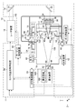
- FIG. 1 is a diagram schematically showing a configuration of an exemplary LPP type EUV light generation system.
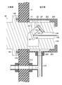
- FIG. 2 is a diagram schematically showing a configuration example of the EUV light sensor unit.
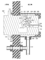
- FIG. 3 is a cross-sectional view schematically showing the configuration of the EUV light sensor unit according to the first embodiment.
- 4 is a cross-sectional view taken along line 4-4 in FIG.
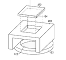
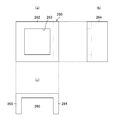
- FIG. 5 is a perspective view showing an example of a spacer. 6A and 6B are three views of the spacer, wherein FIG. 6A is a plan view, FIG. 6B is a side view, and FIG. 6C is a front view.
- FIG. 6A is a plan view
- FIG. 6B is a side view
- FIG. 6C is a front view.
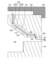
- FIG. 7 is a cross-sectional view of the second photosensor fixed to the sensor holding member.
- FIG. 8 is a cross-sectional view of the filter fixed to the filter holding member.
- FIG. 9 is a cross-sectional view schematically showing the configuration of the EUV light sensor unit according to the second embodiment.
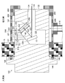
- FIG. 10 is a cross-sectional view schematically showing a main configuration of an EUV light sensor unit according to the third embodiment.
- FIG. 11 is a cross-sectional view schematically showing a configuration of an EUV light sensor unit according to the fourth embodiment.
- Target is an object to be irradiated with laser light introduced into a chamber.
- the target irradiated with the laser light is turned into plasma and emits EUV light.
- the target is a plasma generation source.
- a droplet formed of a liquid target material is one form of the target.
- Pulse laser light may mean laser light including a plurality of pulses.
- Laser light may mean not only pulsed laser light but general laser light.
- Laser optical path means the optical path of laser light.
- Pulsma light is radiation light emitted from a plasma target.
- the emitted light includes EUV light.
- EUV light is an abbreviation for “extreme ultraviolet light”.
- optical component is synonymous with an optical element or an optical member.
- FIG. 1 schematically shows a configuration of an exemplary LPP type EUV light generation system 10.
- the EUV light generation apparatus 11 may be used with at least one laser apparatus 12.
- a system including the EUV light generation apparatus 11 and the laser apparatus 12 is referred to as an EUV light generation system 10.
- the EUV light generation device 11 includes a laser light transmission device 14, a laser light condensing optical system 16, a chamber 18, and an EUV light generation control device 20.
- the target control device 22 and the gas control device 24 are included.
- the laser apparatus 12 may be a MOPA (Master Oscillator Power Amplifier) system.
- the laser device 12 may include a master oscillator (not shown), an optical isolator (not shown), and a plurality of CO 2 laser amplifiers (not shown).
- the wavelength of the laser beam output from the master oscillator is, for example, 10.59 ⁇ m, and the predetermined repetition frequency is, for example, 100 kHz.
- a solid-state laser can be adopted as the master oscillator.
- the laser beam transmission device 14 includes an optical component for defining the traveling direction of the laser beam and an actuator for adjusting the position, posture, and the like of the optical component.
- the laser light transmission device 14 shown in FIG. 1 includes a first high reflection mirror 31 and a second high reflection mirror 32 as optical components for defining the traveling direction of the laser light.
- the laser beam condensing optical system 16 includes a condensing lens 34, a condensing lens holder 35, and a triaxial stage 36.
- the triaxial stage 36 is a stage that can move in directions of three axes orthogonal to each other, that is, the X axis, the Y axis, and the Z axis.
- the direction in which EUV light is derived from the chamber 18 toward the exposure apparatus 100 is taken as the Z axis.
- the direction perpendicular to the paper surface of FIG. 1 is the X axis, and the vertical direction parallel to the paper surface is the Y axis.
- the laser light condensing optical system 16 is configured to condense the laser light transmitted by the laser light transmission device 14 onto the plasma generation region 64 in the chamber 18.
- the chamber 18 is a container that can be sealed.
- the chamber 18 may be formed in, for example, a hollow spherical shape or a cylindrical shape.
- the chamber 18 includes an EUV light collector mirror 40, a plate 41, an EUV light collector mirror holder 42, a first window 44, and a first cover 45.
- the chamber 18 includes a target supply unit 50, a biaxial stage 51, a droplet receiver 52, a droplet detection device 54, an EUV light sensor unit 60, a gas supply device 61, an exhaust device 62, and a pressure. Sensor 63.
- the wall of the chamber 18 is provided with at least one through hole.
- the through hole is closed by the first window 44.
- the pulsed laser light 48 output from the laser device 12 passes through the first window 44 via the condenser lens 34.
- the EUV light collector mirror 40 has, for example, a spheroidal reflecting surface, and has a first focus and a second focus.
- a multilayer reflective film in which molybdenum and silicon are alternately stacked is formed on the surface of the EUV light collector mirror 40.
- the EUV light collector mirror 40 is disposed, for example, such that the first focal point thereof is located in the plasma generation region 64 and the second focal point thereof is located in an intermediate focusing point (IF) 66. .
- IF intermediate focusing point
- a through hole 68 is provided at the center of the EUV light collector mirror 40, and the pulse laser beam 48 passes through the through hole 68.
- the plate 41 and the EUV light collector mirror holder 42 are members that hold the EUV light collector mirror 40.
- the plate 41 is fixed to the chamber 18.
- the EUV light collector mirror 40 is held on the plate 41 via an EUV light collector mirror holder 42.
- the first cover 45 is a shroud that covers an optical path that guides the pulsed laser light 48 from the first window 44 through the through hole 68 to the plasma generation region 64.
- the first cover 45 is configured in a substantially truncated cone shape that tapers from the first window 44 toward the plasma generation region 64.
- the target supply unit 50 is configured to supply a target material into the chamber 18 and is attached so as to penetrate the wall of the chamber 18, for example.
- the target supply unit 50 is attached to the wall of the chamber 18 via the biaxial stage 51.
- the biaxial stage 51 is an XZ axis stage movable in each direction of the X axis and the Z axis.
- the target supply unit 50 can adjust the position in the XZ plane by the biaxial stage 51.
- the material of the target substance may include, but is not limited to, tin, terbium, gadolinium, lithium, xenon, or any combination of two or more thereof.
- the target supply unit 50 is configured to output the droplet 56 formed of the target material toward the plasma generation region 64 inside the chamber 18.
- the target control device 22 is connected to each of the EUV light generation control device 20, the laser device 12, the target supply unit 50, and the droplet detection device 54.
- the target control device 22 controls the operation of the target supply unit 50 in accordance with a command from the EUV light generation control device 20. Further, the target control device 22 controls the output timing of the pulse laser beam 48 of the laser device 12 based on the detection signal from the droplet detection device 54.
- the droplet detection device 54 is configured to detect one or more of the presence, trajectory, position, and speed of the droplet 56.
- the droplet detection device 54 is arranged so as to detect a change in the trajectory in the X direction.
- the droplet detection device 54 includes a light source unit 70 and a light receiving unit 75.
- the light source unit 70 includes a light source 71, an illumination optical system 72, a second window 73, and a second cover 74.
- the light source 71 may be a lamp, a semiconductor laser, or the like.
- the illumination optical system 72 may be a condenser lens that illuminates the droplet trajectory with the light output from the light source 71.
- the light receiving unit 75 includes a transfer optical system 76, a first optical sensor 77, a third window 78, and a third cover 79.
- the transfer optical system 76 may be a lens that transfers the image of the illuminated droplet 56 onto the element of the first optical sensor 77.
- the first optical sensor 77 may be a two-dimensional image sensor such as a CCD (Charge-coupled device).
- the chamber 18 includes another droplet detection device (not shown), and detects the deviation of the trajectory of the droplet 56 in the Z direction by another droplet detection device (not shown).
- the droplet receiver 52 is disposed on an extension line in the direction in which the droplet 56 output from the target supply unit 50 into the chamber 18 travels.
- the droplet 56 is dropped in a direction parallel to the Y axis, and the droplet receiver 52 is disposed at a position facing the target supply unit 50 in the Y direction with respect to the target supply unit 50.
- the EUV light generation apparatus 11 includes a connection portion 82 that allows communication between the inside of the chamber 18 and the inside of the exposure apparatus 100.
- a wall 86 in which an aperture 84 is formed is provided inside the connecting portion 82.
- the wall 86 is arranged such that its aperture 84 is located at the second focal position of the EUV light collector mirror 40.
- the exposure apparatus 100 includes an exposure apparatus controller 102, and the exposure apparatus controller 102 is connected to the EUV light generation control apparatus 20.
- the EUV light sensor unit 60 is a sensor unit that detects EUV light generated in the chamber 18.
- the EUV light sensor unit 60 is connected to the EUV light generation controller 20. There may be a plurality of EUV light sensor units 60 so that plasma can be observed from a plurality of different positions. Although one EUV light sensor unit 60 is shown in FIG. 1, a form in which the EUV light sensor units 60 are installed at a plurality of locations around the chamber 18 is preferable.
- the gas supply device 61 is connected to a space in the first cover 45, the second cover 74, the third cover 79, and the EUV light sensor unit 60 via the pipe 90. Further, the gas supply device 61 is connected to a pipe 91 configured to flow a gas on the surface of the EUV light collector mirror 40.
- the gas supply device 61 is a gas supply source that supplies gas to the pipes 90 and 91.
- the gas supply device 61 can be, for example, a hydrogen gas supply device that supplies hydrogen gas.
- Hydrogen gas is an example of a purge gas.
- the purge gas is not limited to hydrogen gas, and may be a gas containing hydrogen.
- the purge gas is preferably a gas that can react with the material of the target substance to generate a gas that is a compound.
- the kind of purge gas is selected in relation to the material of the target substance.
- the gas control device 24 is connected to each of the EUV light generation control device 20, the gas supply device 61, the exhaust device 62, and the pressure sensor 63.
- the exhaust device 62 exhausts the gas in the chamber 18 to the outside of the chamber 18.
- the pressure sensor 63 detects the pressure in the chamber 18. A detection signal of the pressure sensor 63 is sent to the gas control device 24.
- the gas control device 24 controls the operations of the gas supply device 61 and the exhaust device 62 in accordance with a command from the EUV light generation control device 20.
- the EUV light generation controller 20 is configured to control the entire EUV light generation system 10.
- the EUV light generation controller 20 processes the detection result of the EUV light sensor unit 60.
- the EUV light generation controller 20 may be configured to control, for example, the timing at which the droplet 56 is output, the output direction of the droplet 56, and the like based on the detection result of the droplet detector 54.
- the EUV light generation control device 20 may be configured to control, for example, the oscillation timing of the laser device 12, the traveling direction of the pulse laser light 48, the focusing position of the pulse laser light 48, and the like.
- the various controls described above are merely examples, and other controls may be added as necessary, and some control functions may be omitted.
- control devices such as the EUV light generation control device 20, the target control device 22, the gas control device 24, and the exposure device controller 102 can be realized by a combination of hardware and software of one or a plurality of computers. Is possible. Software is synonymous with program. It is also possible to realize the functions of a plurality of control devices with a single control device. Further, in the present disclosure, the EUV light generation control device 20, the target control device 22, the gas control device 24, the exposure device controller 102, and the like may be connected to each other via a communication network such as a local area network or the Internet. In a distributed computing environment, program units may be stored in both local and remote memory storage devices.
- FIG. 2 is a schematic configuration diagram showing an example of the EUV light sensor unit 60.
- the EUV light sensor unit 60 is mounted through the wall of the chamber 18 that generates EUV light.
- the right side of the wall of the chamber 18 is the inside of the chamber 18, that is, the low pressure side, and the left side of the chamber 18 wall is the atmosphere side.
- the EUV light sensor unit 60 includes an EUV light reflection mirror 121, a filter 122, and a second light sensor 124.
- the EUV light reflection mirror 121 is a mirror made of a multilayer reflection film that selectively reflects light including EUV light among light emitted from plasma.
- the EUV light reflecting mirror 121 can be a mirror made of, for example, a Mo / Si multilayer film in which molybdenum (Mo) and silicon (Si) are alternately stacked.
- the filter 122 is a wavelength filter that selectively transmits the wavelength of the EUV light among the light reflected by the EUV light reflecting mirror 121.
- the wavelength of the EUV light transmitted through the filter 122 is, for example, 13.5 nm.
- the filter 122 is, for example, a metal thin film filter having a film thickness of 300 to 600 nm.
- a metal thin film filter of zirconium (Zr) can be used as an example of the filter 122.
- the film thickness of the filter 122 is 350 nm, for example.
- the filter 122 is disposed so as to cover the light receiving surface of the second optical sensor 124.
- EUV light reflection mirror 121 By combining the reflection characteristics of the EUV light reflection mirror 121 and the transmission characteristics of the filter 122, EUV light having a desired wavelength can be incident on the second optical sensor 124.
- the second optical sensor 124 is a sensor that detects the energy of incident light, such as a photodiode.
- the second optical sensor 124 outputs an electrical signal corresponding to the amount of received light.
- a signal output from the second optical sensor 124 is sent to the EUV light generation controller 20.
- the EUV light sensor unit 60 includes a hollow case 130 that houses the EUV light reflection mirror 121, the filter 122, and the second light sensor 124.
- the case 130 includes an optical component housing part 132, a cylindrical part 134, and a first gas supply part 140.
- the optical component housing part 132 is a space in which the EUV light reflecting mirror 121, the filter 122, and the second optical sensor 124 are housed.
- the EUV light reflecting mirror 121 is held by a mirror holding member (not shown).
- the second optical sensor 124 is attached to a part of the wall surface of the case 130 that defines the optical component housing part 132.
- the filter 122 is held by the filter holding member 123 and is disposed on the front surface of the second optical sensor 124.
- the cylindrical portion 134 has an opening 135 serving as a light incident port for plasma light including EUV light. A part of the cylindrical portion 134 including the opening 135 is disposed inside the chamber 18. The plasma light incident from the opening 135 passes through the cylindrical portion 134 and enters the EUV light reflection mirror 121.
- the first gas supply unit 140 is a gas supply path arranged to supply a purge gas between the EUV light reflection mirror 121 and the filter 122.
- the first gas supply unit 140 includes a first gas inlet 141 and a first gas outlet 142.
- the purge gas introduced into the case 130 from the first gas inlet 141 is ejected from the first gas outlet 142 of the first gas supply unit 140, passes through the cylindrical part 134, and enters the chamber 18 from the opening 135. Spill into.
- the arrow which passes through the 1st gas supply part 140 and the cylindrical-shaped part 134, and exits from the opening part 135 represents gas flow.
- An arrow that passes through the cylindrical portion 134 from the opening 135 and is turned back by the EUV light reflecting mirror 121 and toward the filter 122 and the second optical sensor 124 indicates an optical path of plasma light or EUV light.
- the case 130 includes a flange portion 144.
- the EUV light sensor unit 60 is inserted from the atmosphere side into a through hole provided in the wall of the chamber 18, and is fixed to the chamber 18 via the flange portion 144. That is, the flange portion 144 of the case 130 is disposed outside the chamber 18 and is fixed to the wall of the chamber 18 via the gasket 146.
- the socket 200 into which the case 130 of the EUV light sensor unit 60 is inserted is disposed inside the chamber 18, that is, on the low pressure side.
- the socket 200 is formed so as to cover the low pressure side of the case 130 of the EUV light sensor unit 60.
- the case 130 of the EUV light sensor unit 60 can be inserted into the socket 200 from the atmosphere side of the chamber 18 and the case 130 can be fitted into the socket 200 in the chamber 18. Further, the case 130 can be pulled out to the atmosphere side from the fitting state shown in FIG.
- the socket 200 is configured such that a gap 202 is formed between the outer wall of the case 130 and the inner wall of the socket 200 when the case 130 of the EUV light sensor unit 60 is joined.
- the gap 202 may be formed over the entire inner wall of the socket 200.
- a gap 202 between the inner wall of the socket 200 and the outer wall of the case 130 is formed, and this gap 202 functions as a gas path.
- the inner wall of the socket 200 and the outer wall of the case 130 do not have to be completely sealed, and need not have a sealing structure.
- the concave portion 203 on the inner wall of the socket 200 that can form the gap 202 corresponds to one form of the “gas path forming portion”.
- the socket 200 is provided with a pipe connection portion 206.
- a pipe 210 for supplying gas is connected to the pipe connection portion 206.
- the pipe 210 is stretched around the inner wall of the chamber 18.
- the interior of the pipe 210 connected to the pipe connection portion 206 and the gap 202 communicate with each other.
- a pipe 210 stretched around the inner wall of the chamber 18 may supply gas to a plurality of EUV light sensor units.
- the piping 210 is connected to the gas supply device 61 through the feedthrough 212.
- the feedthroughs 212 for sending gas from the atmosphere side of the chamber 18 to the piping 210 on the vacuum side may be concentrated in one place.
- a first gas inlet 141 is formed in a portion of the EUV light sensor unit 60 facing the gap 202 on the outer wall of the case 130.
- the first gas supply unit 140 connected from the first gas inlet 141 to the first gas outlet 142 is formed so that the gas introduced into the case 130 is blown toward the EUV light reflection mirror 121. . Further, the first gas supply unit 140 is configured not to spray gas directly on the filter 122.
- the first gas outlet 142 opens toward the EUV light reflecting mirror 121, and the gas flowing out from the first gas outlet 142 is blown onto the EUV light reflecting mirror 121. That is, the first gas outlet 142 is provided at a position where the purge gas is blown directly onto the EUV light reflecting mirror 121.
- the first gas outlet 142 is provided at a non-facing position with respect to the filter 122 so as not to blow gas directly to the filter 122. Since the filter 122 is very thin as described above, it is for suppressing deformation and breakage due to the gas to be blown.
- the EUV light generation control device 20 transmits a control signal to the gas control device 24.
- the gas control device 24 controls the gas supply device 61 and the exhaust device 62 so that the pressure in the chamber 18 is within a predetermined range based on the detection value of the pressure sensor 63.
- the predetermined range of the pressure in the chamber 18 is a value between several to several hundreds Pa, for example.
- the hydrogen gas sent out from the gas supply device 61 is supplied through the pipe 90 into each of the first cover 45, the second cover 74, and the third cover 79, and into the EUV light sensor unit 60.
- the The hydrogen gas sent out from the gas supply device 61 is supplied to the reflecting surface of the EUV light collector mirror 40 through the pipe 91.
- the hydrogen gas supplied into the first cover 45 is ejected from the opening 45A of the first cover 45.
- the hydrogen gas supplied into the second cover 74 is ejected from the opening 74 ⁇ / b> A of the second cover 74.
- the hydrogen gas supplied into the third cover 79 is ejected from the opening 79 ⁇ / b> A of the third cover 45.
- the hydrogen gas supplied into the EUV light sensor unit 60 is ejected from the opening 135 of the EUV light sensor unit 60.
- the gas control device 24 transmits a signal to the EUV light generation control device 20 when the internal pressure of the chamber 18 reaches a pressure within a predetermined range. After receiving the signal sent from the gas control device 24, the EUV light generation control device 20 transmits a droplet output instruction signal that instructs the target control device 22 to output a droplet.
- the target control device 22 When the target control device 22 receives the droplet output instruction signal, the target control device 22 transmits the droplet output signal to the target supply unit 50 to output the droplet 56.
- the droplet 56 may be a molten tin (Sn) droplet.
- the trajectory of the droplet 56 output from the target supply unit 50 is detected by the droplet detection device 54.
- a detection signal detected by the droplet detection device 54 is sent to the target control device 22.
- the target control device 22 may transmit a feedback signal to the biaxial stage 51 based on the detection signal obtained from the droplet detection device 54 so that the trajectory of the droplet 56 becomes a desired trajectory.
- the target control device 22 When the trajectory of the droplet 56 is stabilized, the target control device 22 outputs a trigger signal delayed by a predetermined time to the laser device 12 in synchronization with the output signal of the droplet 56. This delay time is set so that the laser beam is irradiated onto the droplet 56 when the droplet 56 reaches the plasma generation region 64.
- the laser device 12 outputs laser light in synchronization with the trigger signal.
- the power of the laser beam output from the laser device 12 reaches several kW to several tens kW.
- Laser light output from the laser device 12 is incident on the condensing lens 34 of the laser light condensing optical system 16 via the laser light transmission device 14.
- the laser light incident on the condenser lens 34 is condensed by the condenser lens 34, passes through the first window 44, and is input to the chamber 18.
- the laser beam condensed by the condenser lens 34 and incident on the chamber 18 is irradiated to the droplet 56 that has reached the plasma generation region 64.
- the droplet 56 is irradiated with at least one pulse included in the pulse laser beam 48.
- the droplets 56 irradiated with the pulsed laser light are turned into plasma, and radiation light 106 is emitted from the plasma.
- the EUV light 108 included in the radiation light 106 is selectively reflected by the EUV light collector mirror 40.
- the EUV light 108 reflected by the EUV light condensing mirror 40 is condensed at the intermediate condensing point 66 and output to the exposure apparatus 100.
- a single droplet 56 may be irradiated with a plurality of pulses included in the pulse laser beam 48.
- the droplet receiver 52 collects a droplet 56 that has passed through the plasma generation region 64 without being irradiated with laser light, or a part of the droplet that has not diffused even when irradiated with laser light.
- plasma When the droplet 56 is irradiated with laser light, plasma can be generated.
- the energy of the generated plasma may be measured by the EUV light sensor unit 60, and the energy of the EUV light included in the generated plasma light may be measured.
- a part of the radiation light 106 that is plasma light enters the EUV light sensor unit 60 from the opening 135, passes through the cylindrical portion 134, and enters the EUV light reflection mirror 121.
- the EUV light reflection mirror 121 reflects EUV light included in the radiation light 106 toward the filter 122. Of the light incident on the filter 122, only light in the EUV wavelength region passes through the filter 122.
- the EUV light transmitted through the filter 122 reaches the light receiving surface of the second photosensor 124.
- the photodiode of the second optical sensor 124 outputs a signal corresponding to the energy of the received EUV light. The energy of the EUV light can be detected based on the signal output from the second optical sensor 124.
- the plasma position can be calculated from the detection position of each EUV light sensor unit and each detection energy.
- Sn debris In the case of the Sn droplet in which the droplet 56 is melted, Sn debris is generated along with the generation of plasma and can be diffused into the chamber 18. In this case, Sn debris refers to Sn fine particles.
- the diffused Sn debris can reach the opening 45A of the first cover 45, the opening 74A of the second cover 74, the opening of the third cover 79, and the opening 135 of the EUV light sensor unit 60.
- Hydrogen gas is emitted from the openings 45A of the first cover 45, the openings 74A of the second cover 74, the openings 79A of the third cover 79, and the openings 135 of the EUV light sensor unit 60. Erupting. For this reason, Sn debris can be prevented from reaching the first window 44, the second window 73, the third window 78, and the EUV light reflecting mirror 121 in the EUV light sensor unit 60.
- the first window 44, the second window 73, and the third window 78 are supplied. Accumulation of Sn debris on 78 is suppressed.
- hydrogen gas is ejected from the first gas outlet 142 of the first gas supply unit 140 in the EUV light sensor unit 60, and hydrogen gas is blown onto the EUV light reflection mirror 121. That is, the purge gas is supplied to the space between the EUV light reflection mirror 121 and the filter 122 from the reflection light path side of the EUV light reflection mirror 121.
- the optical path along which the EUV light reflected by the EUV light reflecting mirror 121 travels toward the filter 122 is the reflected light path of the EUV light reflecting mirror 121.
- the optical path of plasma light that passes through the cylindrical portion 134 from the opening 135 and enters the EUV light reflecting mirror 121 mirror is the incident light path of the EUV light reflecting mirror 121.
- An incident optical path of plasma light to the EUV light reflecting mirror 121 is a first optical path.
- the reflected light path of the EUV light from the EUV light reflecting mirror 121 toward the filter 122 is defined as a second light path.
- the first gas outlet 142 of the first gas supply unit 140 is provided at a position close to the second optical path among the first optical path and the second optical path.
- the axis of the gas supply passage of the first gas supply unit 140 intersects the second optical path, and the gas blown out from the first gas outlet 142 intersects the second optical path. It flows toward the first optical path.
- the first gas supply unit 140 supplies a purge gas between the EUV light reflection mirror 121 and the filter 122 from the second optical path of the first optical path and the second optical path.
- the hydrogen gas ejected from the first gas outlet 142 flows between the EUV light reflection mirror 121 and the filter 122, passes through the cylindrical portion 134, and flows out into the chamber 18 from the opening 135.
- the EUV light reflecting mirror 121 corresponds to one form of a “mirror that reflects extreme ultraviolet light”.
- the second optical sensor 124 corresponds to one form of “an optical sensor that detects extreme ultraviolet light transmitted through a wavelength filter”.
- the cylindrical portion 134 corresponds to one form of a “tube portion”.
- the EUV light sensor unit 60 shown in FIG. 2 supplies gas to the inside of the case 130 and ejects the gas from the opening 135 through the cylindrical portion 134, so that Sn debris reflects EUV light. Reaching the mirror 121 can be suppressed.
- the EUV light sensor unit 60 is limited in size in order to be mounted in the chamber 18 and must have a space-saving design. Further, the EUV light propagates with the beam diameter expanding, and the EUV light is contained within the photodiode effective range in the second optical sensor 124, so that the gap between the filter 122 and the second optical sensor 124 is narrow. It has become.
- an adhesive containing carbon is used for the filter 122 and the second optical sensor 124. Residual carbon in the atmosphere or carbon volatilized from the adhesive used for the filter 122 and the second photosensor 124 can be deposited in the EUV illumination area between the filter 122 and the second photosensor 124 during the EUV illumination. The detection sensitivity of the second optical sensor 124 is lowered due to the influence of carbon deposited on the surface of the filter 122 and / or the second optical sensor 124, which hinders energy measurement.
- FIG. 3 is a cross-sectional view schematically showing the configuration of the EUV light sensor unit according to the first embodiment. Differences from the configuration described in FIG. 2 with respect to the first embodiment illustrated in FIG. 3 will be described. Instead of the EUV light sensor unit 60 described in FIG. 2, an EUV light sensor unit 160 shown in FIG. 3 can be used. 4 is a cross-sectional view taken along line 4-4 in FIG.
- the EUV light sensor unit 160 includes a second gas supply unit 240 arranged to supply a purge gas between the filter 122 and the second light sensor 124.
- the second gas supply unit 240 is a gas supply path that includes a second gas inlet 241 and a second gas outlet 242.
- the case 130 includes a flow path structure unit that is the second gas supply unit 240.
- the second gas inlet 241 is formed in a portion facing the gap 202 on the outer wall of the case 130.
- the second gas outlet 242 is a gas outlet that blows out purge gas between the EUV light reflection mirror 121 and the filter 122.
- the second gas supply unit 240 connected from the second gas inlet 241 to the second gas outlet 242 passes the gas introduced into the case 130 into the gap between the filter 122 and the second photosensor 124. Shaped to guide.
- the gas introduced into the case 130 from the second gas introduction port 241 is ejected from the second gas outlet 242 of the second gas supply unit 240 and passes through the gap between the filter 122 and the second optical sensor 124. And flows out from the opening 135 into the chamber 18.
- a gap space 250 formed between the filter 122 and the second optical sensor 124 serves as a gas flow path through which purge gas flows.
- Both the first gas supply unit 140 and the second gas supply unit 240 communicate with the gap 202 between the socket 200 and the outer wall of the case 130, and the first gas supply unit 140 and the second gas supply are supplied through the gap 202. Gas flows through each of the parts 240.
- the ratio between the flow rate of the first gas supply unit 140 and the flow rate of the second gas supply unit 240 can be realized by adjusting the conductance of each gas flow path.
- the first gas supply unit 140 can be configured using, for example, a pipe having a constant flow path cross-sectional area.
- the 2nd gas supply part 240 can be comprised using the pipe
- the area ratio of the channel cross sections of the first gas supply unit 140 and the second gas supply unit 240 may be, for example, in the range of 5: 1 to 15: 1.
- the filter 122 and the second optical sensor so that the gas supplied between the filter 122 and the second optical sensor 124 from the second gas supply unit 240 flows in one direction without diffusing.
- the side surface 251 of the gas flow path constituted by the space 250 between 124 is closed by the wall member 252.
- the wall member 252 may be a part of a spacer that separates the filter 122 and the second optical sensor 124 by a predetermined distance.
- FIG. 5 is a perspective view showing an example of a spacer.
- FIG. 6 is a three-side view of the spacer 260 shown in FIG. 6A is a plan view, FIG. 6B is a side view, and FIG. 6C is a front view.
- the spacer 260 has a structure in which a first plate 262 in contact with the sensor holding member 270 of the second optical sensor 124, and a second plate 264 and a third plate 265 in contact with the filter holding member 123 are combined in a U shape.
- the first plate 262 is formed with a through hole 263 through which EUV light passes.
- the second optical sensor 124 is fixed to the sensor holding member 270.
- the sensor holding member 270 holding the second optical sensor 124 abuts on the first plate 262 in a state where the positions of the through holes 263 of the first plate 262 and the second optical sensor 124 are matched.
- the second plate 264 and the third plate 265 correspond to the wall member 252 described in FIG.
- the filter 122 and the second optical sensor 124 are arranged in a state of being separated by a predetermined distance by the spacer 260.
- the distance between the filter 122 and the light receiving surface of the second optical sensor 124 can be designed to a desired distance.
- the distance between the filter 122 and the light receiving surface of the second optical sensor 124 is 1.5 mm, whereas in the first embodiment shown in FIG. 3, the distance is 4.0 mm. Composed.
- the space 266 having the second plate 264 and the third plate 265 as side wall surfaces is a space 250 through which purge gas flows.
- FIG. 7 is a cross-sectional view of the second optical sensor 124 held by the sensor holding member 270.
- the second optical sensor 124 is fixed to the sensor holding member 270.
- the sensor holding member 270 is a frame that covers the back surface and side surfaces of the second optical sensor 124.
- the second optical sensor 124 is fixed to the sensor holding member 270 using an adhesive 272.
- the adhesive 272 contains carbon.
- the adhesive 272 is used between the back surface of the second optical sensor 124 and the sensor holding member 270.
- a signal line 124 ⁇ / b> A is connected to the back surface of the second photosensor 124.
- the signal line 124A is drawn through a through hole formed in the sensor holding member 270, and is connected to an electric circuit (not shown).
- the sensor holding member 270 is an example of a holding member that holds the second optical sensor 124.
- FIG. 8 is a cross-sectional view of the filter 122 fixed to the filter holding member 123.
- the filter holding member 123 includes a holding frame 123A and a pressing member 123B.
- the filter 122 is fixed to the holding frame 123A using an adhesive 274 and a pressing member 123B.
- the adhesive 274 contains carbon.
- the adhesive 274 may be the same type of adhesive as the adhesive 272 shown in FIG. 7 or may be a different type of adhesive.
- the adhesive 274 is used between the filter 122 and the pressing member 123B.
- the filter 122 is fixed to the filter holding member 123 while being sandwiched between the holding frame 123A and the pressing member 123B.
- the carbon existing between the filter 122 and the second optical sensor 124 is removed by this purge gas flow.
- the pressure difference between both surfaces of the filter 122 can be made difficult to occur by appropriately setting the channel cross-sectional area and the channel length of the second gas supply unit 240.
- the pressure difference between both surfaces of the filter 122 is preferably 3 kPa or less.
- the flow rate ratio between the first gas supply unit 140 and the second gas supply unit 240 is preferably in the range of 8: 1 to 12: 1.
- the EUV light sensor unit 160 is an example of an “extreme ultraviolet light sensor unit”.
- the first gas supply unit 140 is an example of a “first purge gas supply unit”.
- the purge gas supplied from the first gas supply unit 140 is an example of “first purge gas”.
- the second gas supply unit 240 is an example of a “purge gas supply unit” and a “second purge gas supply unit”.
- the purge gas supplied from the second gas supply unit 240 is an example of a “second purge gas”.
- the EUV light generation apparatus 11 including the EUV light sensor unit 160 is an example of an “extreme ultraviolet light generation apparatus”.
- FIG. 9 is a cross-sectional view schematically showing a configuration of an EUV light sensor unit according to the second embodiment. The difference between the second embodiment shown in FIG. 9 and the configuration of the first embodiment described in FIG. 3 will be described.
- the second gas supply unit 240 of the EUV light sensor unit 160 has a flow path structure that does not blow the purge gas directly toward the surface of the filter 122. As shown in FIG. 9, the second gas supply unit 240 is provided at a position that does not face the filter 122.
- the EUV optical sensor unit 160 has a third flow path that guides the gas that has passed through the space 250 between the filter 122 and the second optical sensor 124 in a direction that is not parallel to the surface of the filter 122.
- the third flow path portion 280 in this example has a flow path structure that guides gas along the horizontal direction of FIG.
- the third flow path portion 280 communicates with the space 250 between the filter 122 and the second photosensor 124, and purge gas that guides the purge gas that has passed between the filter 122 and the second photosensor 124 to the gas outlet 282. Functions as a discharge channel.
- the gas outlet 282 of the third flow path part 280 is provided at a position away from the second optical sensor 124.
- the gas outlet 282 opens downward in FIG.
- the third flow path part 280 is connected to the cylindrical part 134 via the gas outlet 282.
- the purge gas discharge flow path constituted by the third flow path portion 280 is a flow in which the gas flow path from the space 250 between the filter 122 and the second optical sensor 124 to the gas outlet 282 is a non-linear path. Includes road structures.
- the third flow path portion 280 including the flow path structure that constitutes this non-linear path also functions as a shielding structure that suppresses the scattered light including visible light from entering the second optical sensor 124. That is, the flow path wall 284 of the third flow path unit 280 functions as a shielding member that suppresses the entry of scattered light into the space 250 between the filter 122 and the second optical sensor 124. Further, the flow path structure constituting the non-linear path is a structure in which scattered light entering from the gas outlet 282 hardly reaches the light receiving surface of the second photosensor 124.
- the gas introduced from the second gas introduction port 241 is ejected from the second gas outlet 242 through the second gas supply unit 240.
- the gas flowing out from the second gas outlet 242 strikes the wall of the filter holding member 123 or the flow path structure member connected to the filter holding member 123 to change the direction of the flow, and between the filter 122 and the second optical sensor 124. It flows to.
- the gas flowing between the filter 122 and the second photosensor 124 passes through the third flow path portion 280 and is discharged from the gas outlet 282.
- the same actions and effects as in the first embodiment can be obtained. Further, according to the second embodiment, since the second gas supply unit 240 has a flow path structure that does not blow the purge gas directly toward the filter 122, the damage of the filter 122 can be suppressed. In addition, according to the second embodiment, a structure in which scattered light does not easily enter the second optical sensor 124 through the purge gas flow path is provided, and more accurate energy measurement is possible.
- FIG. 10 is a cross-sectional view schematically illustrating a main configuration of an EUV light sensor unit according to the third embodiment.
- FIG. 10 shows a flow path structure portion for flowing purge gas between the filter 122 and the second photosensor 124.
- the difference between the third embodiment shown in FIG. 10 and the configuration of the second embodiment described in FIG. 9 will be described.
- the flow of purge gas flowing between the filter 122 and the second optical sensor 124 is indicated by arrows.
- the second gas supply unit 240 in the third embodiment includes a first flow path part 240A and a second flow path part 240B.
- the first flow path portion 240A is a gas supply path that guides gas from the second gas introduction port 241 downward in FIG.
- the direction of the gas flow passing through the first flow path portion 240A is referred to as a first direction.
- the second flow path portion 240B is a gas supply path that is connected to the first flow path portion 240A and guides the gas toward the diagonally lower right direction in FIG.
- the direction of the gas flow passing through the second flow path portion 240B is referred to as the second direction.
- the second direction is a direction that intersects the first direction and is parallel to the surface of the filter 122.
- the second gas supply unit 240 is configured such that the direction of gas flow is bent at the connection portion between the first flow path portion 240A and the second flow path portion 240B.
- the second flow path portion 240B is connected to the space 250 between the filter 122 and the second photosensor 124.
- a connection part between the second flow path part 240 ⁇ / b> B and the space 250 corresponds to the second gas outlet 242.
- the second gas outlet 242 is provided at a position not facing the filter 122. The purge gas flowing out from the second gas outlet 242 flows along the second direction.
- the gas introduced from the second gas inlet 241 hits the flow path wall of the second flow path part 240B at the connection part of the first flow path part 240A and the second flow path part 240B.
- the flow direction is changed, and the flow flows to the second flow path portion 240B.
- the gas that has passed through the second flow path 240B flows from the second gas outlet 242 to the space 250 between the filter 122 and the second photosensor 124.
- FIG. 11 is a cross-sectional view schematically showing a configuration of an EUV light sensor unit according to the fourth embodiment. The difference between the fourth embodiment shown in FIG. 11 and the configuration of the first embodiment described in FIG. 3 will be described.
- the EUV light sensor unit 160 includes a first diaphragm 301 in the first gas supply unit 140.
- the EUV light sensor unit 160 includes a second diaphragm 302 in the second gas supply unit 240.
- both the first gas supply unit 140 and the second gas supply unit 240 are provided with a restriction, but either the first gas supply unit 140 or the second gas supply unit 240 is provided. It is good also as a form which provides an aperture stop.
- the first restrictor 301 is fixed to the flow path of the first gas supply unit 140 by a first restrictor 311 so as to be replaceable.
- the second restrictor 302 is fixed to the flow path of the second gas supply unit 240 by a second restrictor 322 in a replaceable manner.
- the first gas supply unit 140 includes a first throttle mounting part 315 including a support surface for mounting the first throttle 301.
- the second gas supply unit 240 includes a second throttle mounting part 325 including a support surface for mounting the second throttle 302.
- the flow rate of the gas flowing through the first gas supply unit 140 is adjusted by the first throttle 301.
- the flow rate of the gas flowing through the second gas supply unit 240 is adjusted by the second throttle 302.
- the gas flow rate of each flow path can be adjusted by combining a plurality of types of throttles.
- the first diaphragm 301 and the second diaphragm 302 are examples of “aperture”.
- the type of purge gas supplied between the filter 122 and the second optical sensor 124 may be different from the type of purge gas supplied between the EUV light reflection mirror 121 and the filter 122.
- the purge gas supplied from the second gas supply unit 240 is not limited to hydrogen gas, and may be an inert gas.
Landscapes
- Physics & Mathematics (AREA)
- Spectroscopy & Molecular Physics (AREA)
- General Physics & Mathematics (AREA)
- Optics & Photonics (AREA)
- Engineering & Computer Science (AREA)
- Plasma & Fusion (AREA)
- Exposure And Positioning Against Photoresist Photosensitive Materials (AREA)
- X-Ray Techniques (AREA)
Abstract
本開示の一観点に係る極端紫外光センサユニットは、極端紫外光を反射するミラーと、ミラーによって反射された極端紫外光を選択的に透過する波長フィルタと、波長フィルタを透過した極端紫外光を検出する光センサと、波長フィルタと光センサとの間にパージガスを供給するよう配置されたパージガス供給部と、を備える。
Description
本開示は、極端紫外光センサユニット及び極端紫外光生成装置に関する。
近年、半導体プロセスの微細化に伴って、半導体プロセスの光リソグラフィにおける転写パターンの微細化が急速に進展している。次世代においては、20nm以下の微細加工が要求されるようになる。このため、波長13nm程度の極端紫外(EUV:Extreme Ultra Violet)光を生成するための装置と縮小投影反射光学系とを組み合わせた露光装置の開発が期待されている。
EUV光生成装置としては、ターゲット物質にレーザ光を照射することによって生成されるプラズマが用いられるLPP(Laser Produced Plasma)式の装置と、放電によって生成されるプラズマが用いられるDPP(Discharge Produced Plasma)式の装置と、軌道放射光が用いられるSR(Synchrotron Radiation)式の装置との3種類の装置が提案されている。
本開示の1つの観点に係る極端紫外光センサユニットは、極端紫外光を反射するミラーと、ミラーによって反射された極端紫外光を選択的に透過する波長フィルタと、波長フィルタを透過した極端紫外光を検出する光センサと、波長フィルタと光センサとの間にパージガスを供給するよう配置されたパージガス供給部と、を備える。
本開示のいくつかの実施形態を、単なる例として、添付の図面を参照して以下に説明する。
図1は例示的なLPP式のEUV光生成システムの構成を概略的に示す図である。
図2はEUV光センサユニットの構成例を概略的に示す図である。
図3は実施形態1に係るEUV光センサユニットの構成を概略的に示す断面図である。
図4は図3中の4-4線を切断線とする断面図である。
図5はスペーサの例を示す斜視図である。
図6はスペーサの三面図であり、(a)は平面図、(b)は側面図、(c)は正面図である。
図7はセンサ保持部材に固定された第2の光センサの断面図である。
図8はフィルタ保持部材に固定されたフィルタの断面図である。
図9は実施形態2に係るEUV光センサユニットの構成を概略的に示す断面図である。
図10は実施形態3に係るEUV光センサユニットの要部構成を概略的に示す断面図である。
図11は実施形態4に係るEUV光センサユニットの構成を概略的に示す断面図である。
-目次-
1.用語の説明
2.極端紫外光生成システムの全体説明
2.1 構成
2.2 動作
3.課題
4.実施形態1
4.1 構成
4.2 動作
4.3 作用・効果
5.実施形態2
5.1 構成
5.2 動作
5.3 作用・効果
6.実施形態3
6.1 構成
6.2 動作
6.3 作用・効果
7.実施形態4
7.1 構成
7.2 動作
7.3 作用・効果
8.変形例
以下、本開示の実施形態について、図面を参照しながら詳しく説明する。
1.用語の説明
2.極端紫外光生成システムの全体説明
2.1 構成
2.2 動作
3.課題
4.実施形態1
4.1 構成
4.2 動作
4.3 作用・効果
5.実施形態2
5.1 構成
5.2 動作
5.3 作用・効果
6.実施形態3
6.1 構成
6.2 動作
6.3 作用・効果
7.実施形態4
7.1 構成
7.2 動作
7.3 作用・効果
8.変形例
以下、本開示の実施形態について、図面を参照しながら詳しく説明する。
以下に説明される実施形態は、本開示のいくつかの例を示すものであって、本開示の内容を限定するものではない。また、各実施形態で説明される構成及び動作の全てが本開示の構成及び動作として必須であるとは限らない。なお、同一の構成要素には同一の参照符号を付して、重複する説明を省略する。
1.用語の説明
「ターゲット」は、チャンバに導入されたレーザ光の被照射物である。レーザ光が照射されたターゲットは、プラズマ化してEUV光を放射する。ターゲットは、プラズマの発生源となる。液状のターゲット物質によって形成されるドロップレットは、ターゲットの一形態である。
「ターゲット」は、チャンバに導入されたレーザ光の被照射物である。レーザ光が照射されたターゲットは、プラズマ化してEUV光を放射する。ターゲットは、プラズマの発生源となる。液状のターゲット物質によって形成されるドロップレットは、ターゲットの一形態である。
「パルスレーザ光」は、複数のパルスを含むレーザ光を意味し得る。
「レーザ光」は、パルスレーザ光に限らずレーザ光一般を意味し得る。
「レーザ光路」は、レーザ光の光路を意味する。
「プラズマ光」は、プラズマ化したターゲットから放射された放射光である。当該放射光にはEUV光が含まれている。
「EUV光」という表記は、「極端紫外光」の略語表記である。
「光学部品」という用語は、光学素子、若しくは光学部材と同義である。
2.極端紫外光生成システムの全体説明
2.1 構成
図1に例示的なLPP式のEUV光生成システム10の構成を概略的に示す。EUV光生成装置11は、少なくとも1つのレーザ装置12と共に用いられる場合がある。本開示においては、EUV光生成装置11とレーザ装置12を含むシステムを、EUV光生成システム10と称する。
2.1 構成
図1に例示的なLPP式のEUV光生成システム10の構成を概略的に示す。EUV光生成装置11は、少なくとも1つのレーザ装置12と共に用いられる場合がある。本開示においては、EUV光生成装置11とレーザ装置12を含むシステムを、EUV光生成システム10と称する。
図1に示し、かつ、以下に詳細に説明するように、EUV光生成装置11は、レーザ光伝送装置14と、レーザ光集光光学系16と、チャンバ18と、EUV光生成制御装置20と、ターゲット制御装置22と、ガス制御装置24と、を含んで構成される。
レーザ装置12は、MOPA(Master Oscillator Power Amplifier)システムであってよい。レーザ装置12は、図示せぬマスターオシレータと、図示せぬ光アイソレータと、複数台の図示せぬCO2レーザ増幅器とを含んで構成され得る。マスターオシレータが出力するレーザ光の波長は例えば10.59μmであり、所定の繰り返し周波数は例えば100kHzである。マスターオシレータには固体レーザを採用することができる。
レーザ光伝送装置14は、レーザ光の進行方向を規定するための光学部品と、この光学部品の位置や姿勢等を調整するためのアクチュエータとを備えている。図1に示したレーザ光伝送装置14は、レーザ光の進行方向を規定するための光学部品として、第1の高反射ミラー31と第2の高反射ミラー32とを含む。
レーザ光集光光学系16は、集光レンズ34と集光レンズホルダ35と三軸ステージ36とを含んで構成される。三軸ステージ36は、X軸、Y軸及びZ軸の互いに直交する三軸の方向に移動可能なステージである。図1においてチャンバ18から露光装置100に向かってEUV光を導出する方向をZ軸とする。図1の紙面に垂直な方向をX軸とし、紙面に平行な縦方向をY軸とする。レーザ光集光光学系16は、レーザ光伝送装置14によって伝送されたレーザ光をチャンバ18内のプラズマ生成領域64に集光するよう構成されている。
チャンバ18は密閉可能な容器である。チャンバ18は、例えば、中空の球形状又は筒形状に形成されてもよい。チャンバ18は、EUV光集光ミラー40と、プレート41と、EUV光集光ミラーホルダ42と、第1のウインドウ44と、第1の覆い45と、を備えている。また、チャンバ18は、ターゲット供給部50と、二軸ステージ51と、ドロップレット受け52と、ドロップレット検出装置54と、EUV光センサユニット60と、ガス供給装置61と、排気装置62と、圧力センサ63と、を備えている。
チャンバ18の壁には、少なくとも1つの貫通孔が設けられている。その貫通孔は第1のウインドウ44によって塞がれる。レーザ装置12から出力されるパルスレーザ光48が集光レンズ34を介して第1のウインドウ44を透過する。
EUV光集光ミラー40は、例えば、回転楕円面形状の反射面を有し、第1の焦点及び第2の焦点を有する。EUV光集光ミラー40の表面には、例えば、モリブデンとシリコンとが交互に積層された多層反射膜が形成される。EUV光集光ミラー40は、例えば、その第1の焦点がプラズマ生成領域64に位置し、その第2の焦点が中間集光点(IF:Intermediate Focusing point)66に位置するように配置される。EUV光集光ミラー40の中央部には貫通孔68が設けられ、貫通孔68をパルスレーザ光48が通過する。
プレート41とEUV光集光ミラーホルダ42は、EUV光集光ミラー40を保持する部材である。プレート41はチャンバ18に固定される。EUV光集光ミラー40はEUV光集光ミラーホルダ42を介してプレート41に保持される。
第1の覆い45は、第1のウインドウ44から貫通孔68を通ってプラズマ生成領域64へとパルスレーザ光48を導く光路を覆うシュラウド(shroud)である。第1の覆い45は、第1のウインドウ44からプラズマ生成領域64に向かって先細りする略円錐台形の筒形状に構成されている。
ターゲット供給部50は、ターゲット物質をチャンバ18内部に供給するよう構成され、例えば、チャンバ18の壁を貫通するように取り付けられる。ターゲット供給部50は二軸ステージ51を介してチャンバ18の壁に取り付けられる。二軸ステージ51はX軸及びZ軸の各方向に移動可能なXZ軸ステージである。ターゲット供給部50は二軸ステージ51により、XZ平面内の位置を調整することができる。
ターゲット物質の材料は、スズ、テルビウム、ガドリニウム、リチウム、キセノン、又は、それらの内のいずれか2つ以上の組合せを含んでもよいが、これらに限定されない。ターゲット供給部50は、ターゲット物質により形成されたドロップレット56をチャンバ18内部のプラズマ生成領域64に向けて出力するよう構成される。
ターゲット制御装置22は、EUV光生成制御装置20、レーザ装置12、ターゲット供給部50及びドロップレット検出装置54の各々と接続されている。ターゲット制御装置22は、EUV光生成制御装置20の指令に従い、ターゲット供給部50の動作を制御する。また、ターゲット制御装置22は、ドロップレット検出装置54からの検出信号を基にレーザ装置12のパルスレーザ光48の出力タイミングを制御する。
ドロップレット検出装置54は、ドロップレット56の存在、軌跡、位置、及び速度のうちいずれか又は複数を検出するよう構成される。ドロップレット検出装置54は、X方向の軌道の変化を検出できるように配置される。ドロップレット検出装置54は、光源部70と受光部75を含んでいる。
光源部70は、光源71と、照明光学系72と、第2のウインドウ73と、第2の覆い74とを含んで構成される。光源71は、ランプや半導体レーザ等であってもよい。照明光学系72は、光源71から出力された光によってドロップレット軌道を照明する集光レンズであってもよい。
受光部75は、転写光学系76と、第1の光センサ77と、第3のウインドウ78と、第3の覆い79とを含んで構成される。転写光学系76は照明されたドロップレット56の像を第1の光センサ77の素子上に転写するレンズであってもよい。第1の光センサ77は、CCD(Charge-coupled device)等の2次元のイメージセンサであってもよい。
チャンバ18は、図示しないもう1つのドロップレット検出装置を備えており、図示しないもう1つのドロップレット検出装置によって、ドロップレット56のZ方向の軌道のずれを検出する。
ドロップレット受け52は、ターゲット供給部50からチャンバ18内に出力されたドロップレット56が進行する方向の延長線上に配置される。図1ではドロップレット56の滴下方向がY軸と平行な方向であり、ドロップレット受け52はターゲット供給部50に対してY方向を向いてターゲット供給部50と対向する位置に配置される。
また、EUV光生成装置11は、チャンバ18の内部と露光装置100の内部とを連通させる接続部82を含む。接続部82の内部には、アパーチャ84が形成された壁86が設けられる。壁86は、そのアパーチャ84がEUV光集光ミラー40の第2の焦点位置に位置するように配置される。
露光装置100は露光装置コントローラ102を含んでおり、露光装置コントローラ102はEUV光生成制御装置20と接続される。
EUV光センサユニット60は、チャンバ18内で生成されるEUV光を検出するセンサユニットである。EUV光センサユニット60はEUV光生成制御装置20に接続されている。EUV光センサユニット60は、異なる複数の位置からプラズマを観測できるように複数台あってもよい。図1では1つのEUV光センサユニット60が示されているがチャンバ18の周りの複数箇所にEUV光センサユニット60が設置される形態が好ましい。
ガス供給装置61は、配管90を介して第1の覆い45、第2の覆い74、第3の覆い79、及びEUV光センサユニット60の中の空間に接続されている。さらに、ガス供給装置61は、EUV光集光ミラー40の表面にガスを流すよう構成された配管91に接続されている。ガス供給装置61は配管90、91にガスを供給するガス供給源である。ガス供給装置61は例えば、水素ガスを供給する水素ガス供給装置とすることができる。
水素ガスはパージガスの一例である。パージガスは水素ガスに限らず、水素を含むガスであってもよい。パージガスは、ターゲット物質の材料と反応して化合物である気体を生成し得るガスであることが好ましい。パージガスの種類はターゲット物質の材料との関係で選択される。
ガス制御装置24は、EUV光生成制御装置20、ガス供給装置61、排気装置62及び圧力センサ63の各々と接続される。排気装置62は、チャンバ18内の気体をチャンバ18の外部に排出する。圧力センサ63はチャンバ18内の圧力を検出する。圧力センサ63の検出信号はガス制御装置24に送られる。ガス制御装置24は、EUV光生成制御装置20の指令に従い、ガス供給装置61及び排気装置62の動作を制御する。
EUV光生成制御装置20は、EUV光生成システム10全体の制御を統括するよう構成される。EUV光生成制御装置20は、EUV光センサユニット60の検出結果を処理する。EUV光生成制御装置20は、ドロップレット検出装置54の検出結果に基づいて、例えば、ドロップレット56が出力されるタイミングやドロップレット56の出力方向等を制御するよう構成されてもよい。さらに、EUV光生成制御装置20は、例えば、レーザ装置12の発振タイミング、パルスレーザ光48の進行方向、パルスレーザ光48の集光位置等を制御するよう構成されてもよい。上述の様々な制御は単なる例示に過ぎず、必要に応じて他の制御が追加されてもよいし、一部の制御機能を省略してもよい。
本開示において、EUV光生成制御装置20、ターゲット制御装置22、ガス制御装置24及び露光装置コントローラ102等の制御装置は、1台又は複数台のコンピュータのハードウェア及びソフトウェアの組み合わせによって実現することが可能である。ソフトウェアはプログラムと同義である。また、複数の制御装置の機能を一台の制御装置で実現することも可能である。さらに本開示において、EUV光生成制御装置20、ターゲット制御装置22、ガス制御装置24及び露光装置コントローラ102等は、ローカルエリアネットワークやインターネットといった通信ネットワークを介して互いに接続されてもよい。分散コンピューティング環境において、プログラムユニットは、ローカル及びリモート両方のメモリストレージデバイスに保存されてもよい。
図2はEUV光センサユニット60の一例を示す概略構成図である。EUV光センサユニット60は、EUV光を発生させるチャンバ18の壁を貫通して取り付けられる。図2においてチャンバ18の壁の右側がチャンバ18の内側、つまり低圧側であり、チャンバ18の壁の左側が大気側である。
EUV光センサユニット60は、EUV光反射ミラー121と、フィルタ122と、第2の光センサ124とを含んで構成される。EUV光反射ミラー121は、プラズマから放射される光のうちEUV光を含む光を選択的に反射する多層反射膜によるミラーである。EUV光反射ミラー121は、例えば、モリブデン(Mo)とシリコン(Si)とを交互に積層してなるMo/Si多層膜によるミラーとすることができる。
フィルタ122は、EUV光反射ミラー121によって反射された光のうちEUV光の波長を選択的に透過する波長フィルタである。フィルタ122が透過するEUV光の波長は、例えば13.5nmである。フィルタ122は例えば、膜厚300~600nmの金属薄膜フィルタである。フィルタ122の一例として、ジルコニウム(Zr)の金属薄膜フィルタを用いることができる。フィルタ122の膜厚は、例えば、350nmである。
フィルタ122は、第2の光センサ124の受光面を覆うように配置される。EUV光反射ミラー121の反射特性とフィルタ122の透過特性の組み合わせにより、所望の波長のEUV光を第2の光センサ124に入射させることができる。
第2の光センサ124は、フォトダイオード等、入射した光のエネルギを検出するセンサである。第2の光センサ124は受光量に応じた電気信号を出力する。第2の光センサ124から出力される信号はEUV光生成制御装置20に送られる。
EUV光センサユニット60は、EUV光反射ミラー121と、フィルタ122と、第2の光センサ124とを収容する中空のケース130を備える。ケース130は、光学部品収容部132と円筒形状部134と第1のガス供給部140とを有する。
光学部品収容部132は、EUV光反射ミラー121と、フィルタ122と、第2の光センサ124とが収容される空間である。EUV光反射ミラー121は図示せぬミラー保持部材に保持される。第2の光センサ124は光学部品収容部132を画成するケース130の壁面の一部に取り付けられる。フィルタ122は、フィルタ保持部材123に保持され、第2の光センサ124の前面に配置される。
円筒形状部134は、EUV光を含むプラズマ光の光入射口となる開口部135を有する。開口部135を含む円筒形状部134の一部はチャンバ18の内側に配置される。開口部135から入射したプラズマ光は円筒形状部134を通過してEUV光反射ミラー121に入射する。
第1のガス供給部140は、EUV光反射ミラー121とフィルタ122との間にパージガスを供給するよう配置されたガス供給路である。第1のガス供給部140は、第1のガス導入口141と、第1のガス流出口142とを含む。第1のガス導入口141からケース130に導入されたパージガスは、第1のガス供給部140の第1のガス流出口142から噴出し、円筒形状部134を通って開口部135からチャンバ18内へと流出する。
図2において、第1のガス供給部140及び円筒形状部134を通過して開口部135から出る矢印はガス流を表している。また、開口部135から円筒形状部134を通過してEUV光反射ミラー121によって折り返され、フィルタ122及び第2の光センサ124へと向かう矢印はプラズマ光又はEUV光の光路を表している。
ケース130はフランジ部144を含む。EUV光センサユニット60はチャンバ18の壁に設けられた貫通孔に対して大気側から挿入され、フランジ部144を介してチャンバ18に固定される。すなわち、ケース130のフランジ部144はチャンバ18の外側に配置され、ガスケット146を介してチャンバ18の壁に固定される。
チャンバ18の内側、つまり、低圧側には、EUV光センサユニット60のケース130を挿入するソケット200が配置される。ソケット200は、EUV光センサユニット60のケース130の低圧側を覆うように形成される。
EUV光センサユニット60のケース130をチャンバ18の大気側からソケット200に挿入してケース130をチャンバ18内においてソケット200に嵌合させることができる。また、図2に示された嵌合状態からケース130を大気側に引き抜き、ソケット200からケース130を離脱させることができる。
ソケット200は、EUV光センサユニット60のケース130が接合した際に、ケース130の外壁とソケット200内壁との間に隙間202が形成されるよう構成される。隙間202はソケット200内壁全周に亘って形成されてもよい。チャンバ18の大気側からEUV光センサユニット60のケース130を挿入すると、ソケット200内壁とケース130の外壁との隙間202が形成され、この隙間202がガス経路として機能する。この時、ソケット200の内壁とケース130の外壁は完全に密封された状態でなくても良く、特にシール構造を備えなくともよい。隙間202を形成し得るソケット200の内壁の凹部203が「ガス経路形成部」の一形態に相当する。
ソケット200には配管接続部206が設けられる。この配管接続部206にガスを供給するための配管210が接続される。配管210はチャンバ18の内壁に張り巡らされる。配管接続部206に接続された配管210の内部と隙間202は連通する。チャンバ18の内壁に張り巡らされた配管210は複数のEUV光センサユニットにガスを供給してもよい。
配管210はフィードスルー212を介してガス供給装置61と接続される。チャンバ18の大気側から真空側の配管210にガスを送り込むフィードスルー212は一箇所に集約されてよい。
EUV光センサユニット60のケース130外壁の隙間202に面する部分には第1のガス導入口141が形成される。第1のガス導入口141から第1のガス流出口142へと繋がる第1のガス供給部140は、ケース130内に導入したガスがEUV光反射ミラー121に向けて吹き付けられるように形成される。また、第1のガス供給部140は、フィルタ122に直接ガスを吹き付けないよう構成される。
すなわち、第1のガス流出口142はEUV光反射ミラー121に向かって開口しており、第1のガス流出口142から流出するガスはEUV光反射ミラー121に吹き付けられる。つまり、パージガスがEUV光反射ミラー121に直接吹きつけられる位置に第1のガス流出口142が設けられる。第1のガス流出口142はフィルタ122に対して直接ガスを吹き付けないように、フィルタ122に対して非対面の位置に設けられる。フィルタ122は、既述のように非常に薄いため、吹き付けるガスによる変形や破損を抑制するためである。
2.2 動作
図1及び図2を参照して、例示的なLPP式のEUV光生成システム10の動作を説明する。EUV光生成システム10がEUV光を出力する場合、露光装置100の露光装置コントローラ102からEUV光生成制御装置20にEUV光出力指令が送られる。
図1及び図2を参照して、例示的なLPP式のEUV光生成システム10の動作を説明する。EUV光生成システム10がEUV光を出力する場合、露光装置100の露光装置コントローラ102からEUV光生成制御装置20にEUV光出力指令が送られる。
EUV光生成制御装置20は、ガス制御装置24に制御信号を送信する。ガス制御装置24は、圧力センサ63の検出値に基づいて、チャンバ18内の圧力が所定の範囲内となるように、ガス供給装置61と排気装置62とを制御する。
チャンバ18内の圧力の所定の範囲とは、例えば、数~数百Paの間の値である。ガス供給装置61から送り出された水素ガスは、配管90を通じて第1の覆い45、第2の覆い74及び第3の覆い79の各々の覆いの中、並びにEUV光センサユニット60の中に供給される。また、ガス供給装置61から送り出された水素ガスは、配管91を通じてEUV光集光ミラー40の反射面に供給される。
第1の覆い45の中に供給された水素ガスは、第1の覆い45の開口部45Aから噴出する。第2の覆い74の中に供給された水素ガスは、第2の覆い74の開口部74Aから噴出する。第3の覆い79の中に供給された水素ガスは、第3の覆い45の開口部79Aから噴出する。EUV光センサユニット60の中に供給された水素ガスはEUV光センサユニット60の開口部135から噴出する。
ガス制御装置24は、チャンバ18の内圧が所定の範囲内の圧力となったら、EUV光生成制御装置20に信号を送信する。EUV光生成制御装置20は、ガス制御装置24から送られてくる信号を受信後、ターゲット制御装置22にドロップレット出力を指示するドロップレット出力指示信号を送信する。
ターゲット制御装置22は、ドロップレット出力指示信号を受信すると、ターゲット供給部50にドロップレット出力信号を送信してドロップレット56を出力させる。ドロップレット56は溶融したスズ(Sn)の液滴であってもよい。
ターゲット供給部50から出力したドロップレット56の軌道はドロップレット検出装置54によって検出される。ドロップレット検出装置54による検出された検出信号はターゲット制御装置22に送られる。
ターゲット制御装置22は、ドロップレット検出装置54から得られる検出信号を基に、ドロップレット56の軌道が所望の軌道となるように、二軸ステージ51にフィードバック信号を送信してもよい。
ターゲット制御装置22は、ドロップレット56の軌道が安定したら、ドロップレット56の出力信号に同期して、所定時間遅延したトリガ信号をレーザ装置12に出力する。この遅延時間は、ドロップレット56がプラズマ生成領域64に到達した時にレーザ光がドロップレット56に照射されるように、設定しておく。
レーザ装置12はトリガ信号に同期してレーザ光を出力する。レーザ装置12から出力されるレーザ光のパワーは、数kW~数十kWに達する。レーザ装置12から出力されたレーザ光はレーザ光伝送装置14を介してレーザ光集光光学系16の集光レンズ34に入射する。集光レンズ34に入射したレーザ光は集光レンズ34によって集光され、第1のウインドウ44を通過してチャンバ18に入力される。集光レンズ34によって集光され、チャンバ18に入射したレーザ光は、プラズマ生成領域64に到達したドロップレット56に照射される。
ドロップレット56には、パルスレーザ光48に含まれる少なくとも1つのパルスが照射される。パルスレーザ光が照射されたドロップレット56はプラズマ化し、そのプラズマから放射光106が放射される。放射光106に含まれるEUV光108は、EUV光集光ミラー40によって選択的に反射される。EUV光集光ミラー40によって反射されたEUV光108は、中間集光点66で集光され、露光装置100に出力される。なお、1つのドロップレット56に、パルスレーザ光48に含まれる複数のパルスが照射されてもよい。
ドロップレット受け52は、レーザ光が照射されずにプラズマ生成領域64を通過したドロップレット56や、レーザ光の照射によっても拡散しなかったドロップレットの一部分を回収する。
ドロップレット56にレーザ光が照射されると、プラズマが生成し得る。この生成したプラズマのエネルギをEUV光センサユニット60で計測して、生成したプラズマ光に含まれるEUV光のエネルギを計測してもよい。
プラズマ光である放射光106の一部は、開口部135からEUV光センサユニット60に進入し、円筒形状部134を通過してEUV光反射ミラー121に入射する。EUV光反射ミラー121は放射光106に含まれるEUV光をフィルタ122に向けて反射する。フィルタ122に入射した光のうちEUV波長領域の光のみがフィルタ122を透過する。フィルタ122を透過したEUV光は、第2の光センサ124の受光面に達する。第2の光センサ124のフォトダイオードは、受光したEUV光のエネルギに対応する信号を出力する。第2の光センサ124から出力される信号に基づきEUV光のエネルギを検出することができる。
EUV光センサユニット60を複数配置する場合は、各EUV光センサユニットの検出位置と各検出エネルギからプラズマの位置が計算できる。
ドロップレット56が溶融したSn液滴の場合、プラズマ生成に伴って、Snデブリが生成し、チャンバ18中に拡散し得る。この場合、SnデブリはSn微粒子を指す。拡散したSnデブリは、第1の覆い45の開口部45A、第2の覆い74の開口部74A、第3の覆い79の開口部、及びEUV光センサユニット60の開口部135に到達し得る。
第1の覆い45の開口部45A、第2の覆い74の開口部74A、第3の覆い79の開口部79A、及びEUV光センサユニット60の開口部135の各開口部からは、水素ガスが噴出している。このため、Snデブリが第1のウインドウ44、第2のウインドウ73及び第3のウインドウ78並びにEUV光センサユニット60内のEUV光反射ミラー121に到達するのを抑制し得る。
EUV光集光ミラー40の表面に供給されたガスが水素を含む場合、EUV光集光ミラー40に堆積したSnデブリと水素が反応してスタナンガス(SnH4)を生成する。スタナンガスは排気装置62によってチャンバ18外に排気される。
同様に、第1のウインドウ44、第2のウインドウ73及び第3のウインドウ78の周囲に水素を含むガスが供給されることにより、第1のウインドウ44、第2のウインドウ73及び第3のウインドウ78へのSnデブリの堆積が抑制される。
少なくともEUV光の生成中、EUV光センサユニット60内における第1のガス供給部140の第1のガス流出口142から水素ガスを噴出させ、EUV光反射ミラー121に水素ガスを吹き付ける。すなわち、EUV光反射ミラー121とフィルタ122の間の空間に対し、EUV光反射ミラー121の反射光路側からパージガスを供給する。
EUV光反射ミラー121によって反射されたEUV光がフィルタ122に向かって進行する光路がEUV光反射ミラー121の反射光路である。開口部135から円筒形状部134を通過してEUV光反射ミラー121ミラーに入射するプラズマ光の光路がEUV光反射ミラー121の入射光路である。EUV光反射ミラー121へのプラズマ光の入射光路を第1の光路とする。EUV光反射ミラー121からフィルタ122に向かうEUV光の反射光路を第2の光路とする。第1のガス供給部140の第1のガス流出口142は、第1の光路と第2の光路のうち、第2の光路に近い位置に設けられている。
すなわち、第1のガス供給部140のガス供給通路の軸は、第2の光路と交差しており、第1のガス流出口142から吹き出されたガスは、第2の光路と交差してから第1の光路の方へと流れる。第1のガス供給部140は、第1の光路と第2の光路のうち、第2の光路の方からEUV光反射ミラー121とフィルタ122の間にパージガスを供給する。
第1のガス流出口142から噴出した水素ガスは、EUV光反射ミラー121とフィルタ122の間を流れ、円筒形状部134を通過して開口部135からチャンバ18内へと流出する。
EUV光反射ミラー121は「極端紫外光を反射するミラー」の一形態に相当する。第2の光センサ124は「波長フィルタを透過した極端紫外光を検出する光センサ」の一形態に相当する。円筒形状部134は「管部」の一形態に相当する。
3.課題
図2に示したEUV光センサユニット60は、ケース130の内部にガスを供給し、円筒形状部134を経由して開口部135からガスを噴出させることにより、SnデブリがEUV光反射ミラー121に到達するのを抑制することができる。
図2に示したEUV光センサユニット60は、ケース130の内部にガスを供給し、円筒形状部134を経由して開口部135からガスを噴出させることにより、SnデブリがEUV光反射ミラー121に到達するのを抑制することができる。
円筒形状部134の内径が小さく、円筒形状部134の長さLが長ければ長いほど、Snデブリが進入してきた場合に、水素とSnが反応する可能性が高くなり、より確実にSnデブリをスタナンガス化することができる。その一方で、次のような課題がある。
[課題1]EUV光センサユニット60は、チャンバ18に搭載するために大きさの制限を受け、省スペースな設計でなければならない。また、EUV光はビーム径が拡がりながら伝搬しており、第2の光センサ124におけるフォトダイオード有効範囲内にEUV光を収めるため、フィルタ122と第2の光センサ124との間の隙間が狭くなっている。
[課題2]フィルタ122と第2の光センサ124と間の隙間が狭く、第1のガス供給部140を通じてEUV光センサユニット60内に供給したガスが、フィルタ122と第2の光センサ124と間の隙間に流れることは殆ど無い。
[課題3]フィルタ122や第2の光センサ124には、炭素を含む接着剤が使用されている。大気中の残留炭素又はフィルタ122や第2の光センサ124に使用された接着剤から揮発した炭素がEUV照射中にフィルタ122及び第2の光センサ124間のEUV照射領域内に堆積し得る。このフィルタ122及び/又は第2の光センサ124の表面に堆積した炭素の影響によって第2の光センサ124の検出感度が低下し、エネルギ計測に支障をきたす。
[課題4]課題3に示した炭素の堆積を抑制するために、フィルタ122と第2の光センサ124の付近にガスをパージする場合、フィルタ122の両面での圧力差があるとフィルタ122が損傷し、エネルギ計測に支障をきたす。
4.実施形態1
4.1 構成
図3は実施形態1に係るEUV光センサユニットの構成を概略的に示す断面図である。図3に示す実施形態1に関して図2で説明した構成との相違点を説明する。図2で説明したEUV光センサユニット60に代えて、図3に示すEUV光センサユニット160を用いることができる。図4は図3中の4-4線を切断線とする断面図である。
4.1 構成
図3は実施形態1に係るEUV光センサユニットの構成を概略的に示す断面図である。図3に示す実施形態1に関して図2で説明した構成との相違点を説明する。図2で説明したEUV光センサユニット60に代えて、図3に示すEUV光センサユニット160を用いることができる。図4は図3中の4-4線を切断線とする断面図である。
実施形態1に係るEUV光センサユニット160は、フィルタ122と第2の光センサ124の間にパージガスを供給するよう配置された第2のガス供給部240を備える。第2のガス供給部240は、第2のガス導入口241と第2のガス流出口242とを含むガス供給路である。ケース130は、第2のガス供給部240である流路構造部を備える。
第2のガス導入口241は、ケース130外壁の隙間202に面する部分に形成される。第2のガス流出口242は、EUV光反射ミラー121とフィルタ122との間に向かってパージガスを吹き出すガス流出口である。第2のガス導入口241から第2のガス流出口242へと繋がる第2のガス供給部240は、ケース130内に導入したガスをフィルタ122と第2の光センサ124の間の隙間へと導くよう形成される。
第2のガス導入口241からケース130に導入されたガスは、第2のガス供給部240の第2のガス流出口242から噴出し、フィルタ122と第2の光センサ124の間の隙間を通って開口部135からチャンバ18内へと流出する。フィルタ122と第2の光センサ124の間に形成される隙間の空間250は、パージガスが流れるガス流路となる。
第1のガス供給部140と第2のガス供給部240は共に、ソケット200とケース130外壁との隙間202に連通しており、隙間202を通じて第1のガス供給部140と第2のガス供給部240の各々にガスが流れる。第1のガス供給部140の流量と、第2のガス供給部240の流量の比率は、それぞれのガス流路のコンダクタンスを調整することにより所望の比率を実現できる。
第1のガス供給部140は、例えば、流路断面積が一定である管を用いて構成することができる。同様に、第2のガス供給部240は、流路断面積が一定である管を用いて構成することができる。この場合、第1のガス供給部140と第2のガス供給部240の流路断面の面積比は、例えば、5:1から15:1の範囲でもよい。
図4に示すように、第2のガス供給部240からフィルタ122と第2の光センサ124の間に供給されたガスが拡散せず一方向に流れるように、フィルタ122と第2の光センサ124の間の空間250によって構成されるガス流路の側面251は、壁部材252によって塞がれている。この壁部材252は、フィルタ122と第2の光センサ124とを、所定の距離を離して離間させるスペーサの一部であってよい。
図5はスペーサの例を示す斜視図である。図6は図5に示したスペーサ260の三面図である。図6の(a)は平面図、図6の(b)は側面図、図6の(c)は正面図である。スペーサ260は、第2の光センサ124のセンサ保持部材270と接する第1のプレート262と、フィルタ保持部材123と接する第2のプレート264及び第3のプレート265がU字状に組み合わされた構造を有する。
第1のプレート262には、EUV光を通過させる貫通穴263が形成されている。第2の光センサ124はセンサ保持部材270に固定されている。第2の光センサ124を保持したセンサ保持部材270は、第1のプレート262の貫通穴263と第2の光センサ124の位置を一致させた状態で第1のプレート262に当接する。
第2のプレート264及び第3のプレート265は、図3で説明した壁部材252に相当する。フィルタ122と第2の光センサ124は、スペーサ260によって所定の距離だけ離れた状態で配置される。スペーサ260を用いることにより、フィルタ122と第2の光センサ124の受光面の距離を所望の距離に設計することができる。例えば、図2に示した例では、フィルタ122と第2の光センサ124の受光面の距離が1.5mmであるのに対し、図3に示す実施形態1では、その距離が4.0mmに構成される。
図6の(c)に示した第2のプレート264と第3のプレート265を側壁面とする空間266は、パージガスが流れる空間250となる。
図7はセンサ保持部材270に保持された第2の光センサ124の断面図である。第2の光センサ124は、センサ保持部材270に固定されている。センサ保持部材270は、第2の光センサ124の背面及び側面を覆う枠体である。第2の光センサ124は接着剤272を用いてセンサ保持部材270に固定されている。接着剤272は、炭素を含有する。接着剤272は、第2の光センサ124の背面とセンサ保持部材270の間に用いられる。第2の光センサ124の背面には、信号線124Aが接続されている。信号線124Aは、センサ保持部材270に形成された貫通穴を通して引き出されており、図示せぬ電気回路と接続される。センサ保持部材270は、第2の光センサ124を保持する保持部材の一例である。
図8はフィルタ保持部材123に固定されたフィルタ122の断面図である。フィルタ保持部材123は、保持枠123Aと押さえ部材123Bとを含む。フィルタ122は、接着剤274と押さえ部材123Bとを用いて保持枠123Aに固定される。
接着剤274は、炭素を含有する。接着剤274は、図7に示した接着剤272と同種の接着剤であってもよいし、異なる種類の接着剤であってもよい。接着剤274は、フィルタ122と押さえ部材123Bの間に用いられる。フィルタ122は、保持枠123Aと押さえ部材123Bとの間に挟まれた状態でフィルタ保持部材123に固定される。
4.2 動作
少なくともEUV光の生成中、EUV光センサユニット60内の第2のガス供給部240の第2のガス流出口242から水素ガスを噴出させ、フィルタ122と第2の光センサ124の間にパージガスを供給する。パージガスは、フィルタ122と第2の光センサ124の間の空間250を流れる。
少なくともEUV光の生成中、EUV光センサユニット60内の第2のガス供給部240の第2のガス流出口242から水素ガスを噴出させ、フィルタ122と第2の光センサ124の間にパージガスを供給する。パージガスは、フィルタ122と第2の光センサ124の間の空間250を流れる。
このパージガスの流れによって、フィルタ122と第2の光センサ124の間に存在する炭素が除去される。
第2のガス供給部240の流路断面積及び流路長さを適切に設定することで、フィルタ122の両面での圧力差が生じにくいようにすることができる。フィルタ122の両面の圧力差は3kPa以下であることが好ましい。第1のガス供給部140と第2のガス供給部240の流量比は8:1から12:1の範囲であることが好ましい。
EUV光センサユニット160は、「極端紫外光センサユニット」の一例である。第1のガス供給部140は、「第1のパージガス供給部」の一例である。第1のガス供給部140から供給されるパージガスは「第1のパージガス」の一例である。第2のガス供給部240は、「パージガス供給部」及び「第2のパージガス供給部」の一例である。第2のガス供給部240から供給されるパージガスは「第2のパージガス」の一例である。EUV光センサユニット160を備えたEUV光生成装置11は「極端紫外光生成装置」の一例である。
4.3 作用・効果
実施形態1によれば、フィルタ122及び第2の光センサ124への炭素の付着による透過率の低下や感度低下を抑制することができる。
実施形態1によれば、フィルタ122及び第2の光センサ124への炭素の付着による透過率の低下や感度低下を抑制することができる。
5.実施形態2
5.1 構成
図9は実施形態2に係るEUV光センサユニットの構成を概略的に示す断面図である。図9に示す実施形態2に関して図3で説明した実施形態1の構成との相違点を説明する。
5.1 構成
図9は実施形態2に係るEUV光センサユニットの構成を概略的に示す断面図である。図9に示す実施形態2に関して図3で説明した実施形態1の構成との相違点を説明する。
実施形態2に係るEUV光センサユニット160の第2のガス供給部240は、フィルタ122の表面に向かって直接にパージガスを吹き出さない流路構造となっている。図9に示すように、第2のガス供給部240は、フィルタ122に対して非対面の位置に設けられている。
また、実施形態2に係るEUV光センサユニット160は、フィルタ122と第2の光センサ124の間の空間250を通過したガスを、フィルタ122の表面と非平行な方向に導く第3の流路部280を備える。本例における第3の流路部280は、図9の横方向に沿ってガスを導く流路構造を有する。第3の流路部280は、フィルタ122と第2の光センサ124の間の空間250と連通し、フィルタ122と第2の光センサ124の間を通過したパージガスをガス出口282へと導くパージガス排出流路として機能する。第3の流路部280のガス出口282は、第2の光センサ124から離れた位置に設けられている。ガス出口282は、図9の下方向に向かって開口している。第3の流路部280は、ガス出口282を介して円筒形状部134と繋がっている。
第3の流路部280によって構成されるパージガス排出流路は、フィルタ122と第2の光センサ124の間の空間250からガス出口282までのガスの流れの経路が非直線の経路となる流路構造を含んでいる。
この非直線の経路を構成する流路構造を含む第3の流路部280は、第2の光センサ124に可視光を含む散乱光が入射するのを抑制する遮蔽構造としても機能する。すなわち、第3の流路部280の流路壁284は、フィルタ122と第2の光センサ124の間の空間250への散乱光の進入を抑制する遮蔽部材として機能する。また、非直線の経路を構成する流路構造は、ガス出口282から進入した散乱光が第2の光センサ124の受光面に到達し難い構造である。
5.2 動作
第2のガス導入口241から導入されたガスは、第2のガス供給部240を通って第2のガス流出口242から噴出される。第2のガス流出口242から流れ出たガスは、フィルタ保持部材123又はフィルタ保持部材123に連結された流路構造部材の壁に当たって流れの向きを変え、フィルタ122と第2の光センサ124の間へと流れる。
第2のガス導入口241から導入されたガスは、第2のガス供給部240を通って第2のガス流出口242から噴出される。第2のガス流出口242から流れ出たガスは、フィルタ保持部材123又はフィルタ保持部材123に連結された流路構造部材の壁に当たって流れの向きを変え、フィルタ122と第2の光センサ124の間へと流れる。
フィルタ122と第2の光センサ124の間を流れたガスは、第3の流路部280を通って、ガス出口282から排出される。
5.3 作用・効果
実施形態2によれば、第1実施形態と同様の作用及び効果が得られる。また、実施形態2によれば、第2のガス供給部240がフィルタ122に向けて直接パージガスを吹き出さない流路構造を有しているため、フィルタ122の破損を抑制することができる。また、実施形態2によれば、パージガスの流路を通じて第2の光センサ124に散乱光が入射し難い構造を備えており、より正確なエネルギ計測が可能である。
実施形態2によれば、第1実施形態と同様の作用及び効果が得られる。また、実施形態2によれば、第2のガス供給部240がフィルタ122に向けて直接パージガスを吹き出さない流路構造を有しているため、フィルタ122の破損を抑制することができる。また、実施形態2によれば、パージガスの流路を通じて第2の光センサ124に散乱光が入射し難い構造を備えており、より正確なエネルギ計測が可能である。
6.実施形態3
6.1 構成
図10は実施形態3に係るEUV光センサユニットの要部構成を概略的に示す断面図である。図10は、フィルタ122と第2の光センサ124の間にパージガスを流すための流路構造部分を示している。図10に示す実施形態3に関して図9で説明した実施形態2の構成との相違点を説明する。図10において、フィルタ122と第2の光センサ124の間を流れるパージガスの流れを矢印によって示した。
6.1 構成
図10は実施形態3に係るEUV光センサユニットの要部構成を概略的に示す断面図である。図10は、フィルタ122と第2の光センサ124の間にパージガスを流すための流路構造部分を示している。図10に示す実施形態3に関して図9で説明した実施形態2の構成との相違点を説明する。図10において、フィルタ122と第2の光センサ124の間を流れるパージガスの流れを矢印によって示した。
実施形態3における第2のガス供給部240は、第1の流路部240Aと第2の流路部240Bを含んで構成される。第1の流路部240Aは、第2のガス導入口241から図10の下方向に向かってガスを導くガス供給路である。第1の流路部240Aを通るガス流の方向を第1の方向という。第2の流路部240Bは、第1の流路部240Aに接続され、図10の右斜め下方向に向かってガスを導くガス供給路である。第2の流路部240Bを通るガス流の方向を第2の方向という。第2の方向は、第1の方向と交差する方向であり、フィルタ122の表面に平行な方向である。
第2のガス供給部240は、第1の流路部240Aと第2の流路部240Bの接続部においてガスの流れの向きが屈曲するよう構成される。第2の流路部240Bは、フィルタ122と第2の光センサ124との間の空間250に接続されている。第2の流路部240Bと空間250との接続部が第2のガス流出口242に相当する。第2のガス流出口242は、フィルタ122に対して非対面の位置に設けられている。第2のガス流出口242から流れ出るパージガスは、第2の方向に沿って流れる。
6.2 動作
第2のガス導入口241から導入されたガスは、第1の流路部240Aと第2の流路部240Bの接続部において、第2の流路部240Bの流路壁に当たって流れの向きを変え、第2の流路部240Bへと流れる。第2の流路部240Bを通過したガスは、第2のガス流出口242からフィルタ122と第2の光センサ124の間の空間250に流れる。
第2のガス導入口241から導入されたガスは、第1の流路部240Aと第2の流路部240Bの接続部において、第2の流路部240Bの流路壁に当たって流れの向きを変え、第2の流路部240Bへと流れる。第2の流路部240Bを通過したガスは、第2のガス流出口242からフィルタ122と第2の光センサ124の間の空間250に流れる。
6.3 作用・効果
第3実施形態によれば、第2実施形態と同様の効果が得られる。
第3実施形態によれば、第2実施形態と同様の効果が得られる。
7.実施形態4
7.1 構成
図11は実施形態4に係るEUV光センサユニットの構成を概略的に示す断面図である。図11に示す実施形態4に関して図3で説明した実施形態1の構成との相違点を説明する。
7.1 構成
図11は実施形態4に係るEUV光センサユニットの構成を概略的に示す断面図である。図11に示す実施形態4に関して図3で説明した実施形態1の構成との相違点を説明する。
実施形態4に係るEUV光センサユニット160は、第1のガス供給部140に第1の絞り301を備える。また、EUV光センサユニット160は、第2のガス供給部240に第2の絞り302を備える。図11の例では、第1のガス供給部140と第2のガス供給部240の両方に絞りを設けたが、第1のガス供給部140と第2のガス供給部240のいずれか一方に絞りを設ける形態としてもよい。
第1の絞り301は、第1の絞り押さえ311によって、第1のガス供給部140の流路に交換可能に固定される。第2の絞り302は、第2の絞り押さえ322によって、第2のガス供給部240の流路に交換可能に固定される。第1のガス供給部140は、第1の絞り301を取り付けるための支持面を含む第1の絞り取付部315を備える。
第2のガス供給部240は、第2の絞り302を取り付けるための支持面を含む第2の絞り取付部325を備える。
7.2 動作
第1の絞り301によって第1のガス供給部140を流れるガスの流量が調整される。第2の絞り302によって第2のガス供給部240を流れるガスの流量が調整される。複数種の絞りを組み合わせて各流路のガス流量を調整することができる。第1の絞り301と第2の絞り302は「絞り」の一例である。
第1の絞り301によって第1のガス供給部140を流れるガスの流量が調整される。第2の絞り302によって第2のガス供給部240を流れるガスの流量が調整される。複数種の絞りを組み合わせて各流路のガス流量を調整することができる。第1の絞り301と第2の絞り302は「絞り」の一例である。
7.3 作用・効果
実施形態4によれば、実施形態1と同様の効果が得られる。また、実施形態4によれば、装置のアップグレード等によりチャンバ内圧やガス供給装置61の供給圧が変更されても、適切なパージ条件に調整できる。
実施形態4によれば、実施形態1と同様の効果が得られる。また、実施形態4によれば、装置のアップグレード等によりチャンバ内圧やガス供給装置61の供給圧が変更されても、適切なパージ条件に調整できる。
8.変形例
上述の実施形態では、ソケット200を利用して、第1のガス供給部140と第2のガス供給部240に同種のガス(水素ガス)を導入する例を説明したが、第1のガス供給部140にガスを導入する経路と、第2のガス供給部240にガスを導入する経路とをそれぞれ独立に設ける形態としてもよい。
上述の実施形態では、ソケット200を利用して、第1のガス供給部140と第2のガス供給部240に同種のガス(水素ガス)を導入する例を説明したが、第1のガス供給部140にガスを導入する経路と、第2のガス供給部240にガスを導入する経路とをそれぞれ独立に設ける形態としてもよい。
また、フィルタ122と第2の光センサ124の間に供給するパージガスの種類は、EUV光反射ミラー121とフィルタ122の間に供給するパージガスの種類と異なる種類であってもよい。例えば、第2のガス供給部240から供給するパージガスは、水素ガスに限らず、不活性ガスであってもよい。
上記の説明は、制限ではなく単なる例示を意図している。従って、添付の特許請求の範囲を逸脱することなく本開示の実施形態に変更を加えることができることは、当業者には明らかであろう。
本明細書及び添付の特許請求の範囲全体で使用される用語は、「限定的でない」用語と解釈されるべきである。例えば、「含む」又は「含まれる」という用語は、「含まれるものとして記載されたものに限定されない」と解釈されるべきである。「有する」という用語は、「有するものとして記載されたものに限定されない」と解釈されるべきである。また、本明細書、及び添付の特許請求の範囲に記載される不定冠詞「1つの」は、「少なくとも1つ」又は「1又はそれ以上」を意味すると解釈されるべきである。
Claims (20)
- 極端紫外光を反射するミラーと、
前記ミラーによって反射された極端紫外光を選択的に透過する波長フィルタと、
前記波長フィルタを透過した前記極端紫外光を検出する光センサと、
前記波長フィルタと前記光センサとの間にパージガスを供給するよう配置されたパージガス供給部と、
を備える極端紫外光センサユニット。 - 請求項1に記載の極端紫外光センサユニットであって、
前記波長フィルタと前記光センサとを、所定の距離を離して離間させるスペーサを備え、
前記スペーサによって前記波長フィルタと前記光センサとの間に形成された隙間に、前記パージガス供給部から前記パージガスが供給される極端紫外光センサユニット。 - 請求項2に記載の極端紫外光センサユニットであって、
前記スペーサは、前記波長フィルタと前記光センサの隙間を流れる前記パージガスの拡散を抑制し、前記パージガスが一方向に向かって流れるよう前記パージガスの流路の側面を塞ぐ壁部材を含む極端紫外光センサユニット。 - 請求項1に記載の極端紫外光センサユニットであって、
前記波長フィルタ及び前記光センサは、炭素を含有する接着剤を用いて、それぞれ保持部材に固定されている極端紫外光センサユニット。 - 請求項1に記載の極端紫外光センサユニットであって、
前記ミラーと前記波長フィルタとの間に前記パージガスと同種又は異種の第1のパージガスを供給するよう配置された第1のパージガス供給部と、
前記波長フィルタと前記光センサとの間に前記パージガスである第2のパージガスを供給するよう配置された前記パージガス供給部である第2のパージガス供給部と、
を含む極端紫外光センサユニット。 - 請求項5に記載の極端紫外光センサユニットであって、
前記第1のパージガス供給部を通じて前記ミラーと前記波長フィルタとの間に供給される前記第1のパージガスと、前記第2のパージガス供給部を通じて前記波長フィルタと前記光センサとの間に供給される前記第2のパージガスとによる前記波長フィルタの両面の圧力差が3kPa以下である極端紫外光センサユニット。 - 請求項5に記載の極端紫外光センサユニットであって、
前記第1のパージガス供給部と前記第2のパージガス供給部の流路断面の面積比が5:1から15:1の範囲である極端紫外光センサユニット。 - 請求項5に記載の極端紫外光センサユニットであって、
前記第1のパージガス供給部と前記第2のパージガス供給部の流量比が8:1から12:1の範囲である極端紫外光センサユニット。 - 請求項5に記載の極端紫外光センサユニットであって、
前記第1のパージガス供給部及び前記第2のパージガス供給部の少なくとも一方は、ガス流量を調整するための絞りを含む極端紫外光センサユニット。 - 請求項9に記載の極端紫外光センサユニットであって、
前記第1のパージガス供給部及び前記第2のパージガス供給部の少なくとも一方は、前記絞りを交換可能に固定する絞り取付部を含む極端紫外光センサユニット。 - 請求項1に記載の極端紫外光センサユニットであって、
前記パージガス供給部は、前記波長フィルタの表面に向かって直接に前記パージガスを吹き出さない流路構造を含む極端紫外光センサユニット。 - 請求項1に記載の極端紫外光センサユニットであって、
前記パージガス供給部は、前記波長フィルタと前記光センサの隙間に前記パージガスを流出させるガス流出口を含み、
前記ガス流出口は、前記波長フィルタに対して非対面の位置に設けられている極端紫外光センサユニット。 - 請求項1に記載の極端紫外光センサユニットであって、
前記パージガス供給部は、
ガス導入口と、
前記ガス導入口から第1の方向に向かって前記パージガスを導く第1の流路部と、
前記第1の流路部に接続され、前記第1の方向と交差する第2の方向に前記パージガスを導く第2の流路部と、を含み、
前記第2の方向は、前記波長フィルタの表面に平行な方向であり、
前記第1の流路部と前記第2の流路部との接続部にて前記パージガスの流れの向きを屈曲させて、前記第2の流路部を通して前記第2の方向から前記波長フィルタと前記光センサとの間に前記パージガスを供給する極端紫外光センサユニット。 - 請求項1に記載の極端紫外光センサユニットであって、
前記パージガスのガス流路から前記光センサに可視光を含む散乱光が入射するのを抑制する遮蔽構造を備える極端紫外光センサユニット。 - 請求項1に記載の極端紫外光センサユニットであって、
前記波長フィルタと前記光センサの間の空間に連通し、前記波長フィルタと前記光センサの間を通過した前記パージガスを前記波長フィルタの表面と非平行な方向に導く第3の流路部を備える極端紫外光センサユニット。 - 請求項1に記載の極端紫外光センサユニットであって、
前記波長フィルタと前記光センサの間の空間と連通し、前記波長フィルタと前記光センサの間を通過した前記パージガスを、前記光センサから離れた位置のガス出口へと導くパージガス排出流路を備え、
前記パージガス排出流路は、前記波長フィルタと前記光センサの間の空間から前記ガス出口までのガスの流れの経路が非直線の経路となる流路構造を含む極端紫外光センサユニット。 - 請求項1に記載の極端紫外光センサユニットであって、
前記ミラーに入射させる前記極端紫外光を含むプラズマ光及び前記パージガス供給部から供給された前記パージガスを通過させる管部であって、前記プラズマ光の光入射口となる開口部を有し、前記開口部から入射する前記プラズマ光を前記ミラーに向けて通過させるとともに、前記ミラーと前記波長フィルタとの間を流れた前記パージガスを前記開口部から流出させる管部を含む極端紫外光センサユニット。 - 請求項17に記載の極端紫外光センサユニットであって、
前記ミラー、前記波長フィルタ、及び前記光センサを収容するケースを備え、
前記ケースに前記管部と前記パージガス供給部とが設けられている極端紫外光センサユニット。 - 請求項18に記載の極端紫外光センサユニットであって、
前記ケースの外側に嵌合するソケットを備え、
前記ソケットは、前記ケースの外壁と前記ソケットの内壁との間にガス経路となる隙間を形成するガス経路形成部と、
前記ガス経路形成部に連通する配管接続部と、
を有し、
前記ケースの外壁と前記ソケットの内壁との間に形成される前記隙間を通じて前記ケースの中に前記パージガスが供給される極端紫外光センサユニット。 - 請求項1に記載の極端紫外光センサユニットと、
レーザ光が内部に導入されるチャンバと、
前記チャンバ内にターゲットを供給するターゲット供給部と、
を備え、
前記ターゲット供給部から前記チャンバ内に供給された前記ターゲットに前記レーザ光を照射することにより前記ターゲットをプラズマ化して極端紫外光を生成する極端紫外光生成装置。
Priority Applications (3)
| Application Number | Priority Date | Filing Date | Title |
|---|---|---|---|
| PCT/JP2017/021678 WO2018229838A1 (ja) | 2017-06-12 | 2017-06-12 | 極端紫外光センサユニット及び極端紫外光生成装置 |
| JP2019524574A JP6895518B2 (ja) | 2017-06-12 | 2017-06-12 | 極端紫外光センサユニット |
| US16/673,548 US11125613B2 (en) | 2017-06-12 | 2019-11-04 | Extreme ultraviolet light sensor unit and extreme ultraviolet light generation apparatus |
Applications Claiming Priority (1)
| Application Number | Priority Date | Filing Date | Title |
|---|---|---|---|
| PCT/JP2017/021678 WO2018229838A1 (ja) | 2017-06-12 | 2017-06-12 | 極端紫外光センサユニット及び極端紫外光生成装置 |
Related Child Applications (1)
| Application Number | Title | Priority Date | Filing Date |
|---|---|---|---|
| US16/673,548 Continuation US11125613B2 (en) | 2017-06-12 | 2019-11-04 | Extreme ultraviolet light sensor unit and extreme ultraviolet light generation apparatus |
Publications (1)
| Publication Number | Publication Date |
|---|---|
| WO2018229838A1 true WO2018229838A1 (ja) | 2018-12-20 |
Family
ID=64660362
Family Applications (1)
| Application Number | Title | Priority Date | Filing Date |
|---|---|---|---|
| PCT/JP2017/021678 Ceased WO2018229838A1 (ja) | 2017-06-12 | 2017-06-12 | 極端紫外光センサユニット及び極端紫外光生成装置 |
Country Status (3)
| Country | Link |
|---|---|
| US (1) | US11125613B2 (ja) |
| JP (1) | JP6895518B2 (ja) |
| WO (1) | WO2018229838A1 (ja) |
Cited By (1)
| Publication number | Priority date | Publication date | Assignee | Title |
|---|---|---|---|---|
| US11272608B2 (en) * | 2018-11-15 | 2022-03-08 | Gigaphoton Inc. | Extreme ultraviolet light generation apparatus and electronic device manufacturing method |
Families Citing this family (3)
| Publication number | Priority date | Publication date | Assignee | Title |
|---|---|---|---|---|
| JP7471906B2 (ja) * | 2020-05-11 | 2024-04-22 | ギガフォトン株式会社 | 極端紫外光生成装置、ターゲット制御方法、及び電子デバイスの製造方法 |
| US11650508B2 (en) * | 2020-06-12 | 2023-05-16 | Taiwan Semiconductor Manufacturing Co., Ltd. | Plasma position control for extreme ultraviolet lithography light sources |
| US20240369939A1 (en) * | 2023-05-03 | 2024-11-07 | Taiwan Semiconductor Manufacturing Company Ltd. | Extreme ultraviolet (euv) radiation source apparatus, euv lithography system, and method for generating extreme ultraviolet radiation |
Citations (5)
| Publication number | Priority date | Publication date | Assignee | Title |
|---|---|---|---|---|
| JPH1161081A (ja) * | 1997-08-27 | 1999-03-05 | Hitachi Chem Co Ltd | 光学接着剤及びこれを用いた光学部品 |
| JP2005069854A (ja) * | 2003-08-25 | 2005-03-17 | Canon Inc | Euv光源スペクトル計測装置 |
| JP2007109451A (ja) * | 2005-10-12 | 2007-04-26 | Komatsu Ltd | 極端紫外光源装置の初期アライメント方法 |
| JP2010147138A (ja) * | 2008-12-17 | 2010-07-01 | Ushio Inc | 極端紫外光光源装置および極端紫外光光源装置の保守方法 |
| JP2012119099A (ja) * | 2010-11-29 | 2012-06-21 | Komatsu Ltd | 極端紫外光源装置及びチャンバ装置 |
Family Cites Families (8)
| Publication number | Priority date | Publication date | Assignee | Title |
|---|---|---|---|---|
| JP2004103773A (ja) | 2002-09-09 | 2004-04-02 | Nikon Corp | X線発生装置、x線露光装置及びx線フィルター |
| US7196342B2 (en) | 2004-03-10 | 2007-03-27 | Cymer, Inc. | Systems and methods for reducing the influence of plasma-generated debris on the internal components of an EUV light source |
| TWI305296B (en) | 2004-07-27 | 2009-01-11 | Cymer Inc | Systems and methods for reducing the influence of plasma-generated debris on the internal components of an euv light source |
| US7355672B2 (en) | 2004-10-04 | 2008-04-08 | Asml Netherlands B.V. | Method for the removal of deposition on an optical element, method for the protection of an optical element, device manufacturing method, apparatus including an optical element, and lithographic apparatus |
| US8445876B2 (en) * | 2008-10-24 | 2013-05-21 | Gigaphoton Inc. | Extreme ultraviolet light source apparatus |
| JP2010123929A (ja) * | 2008-10-24 | 2010-06-03 | Gigaphoton Inc | 極端紫外光光源装置 |
| JP2012216743A (ja) * | 2010-06-16 | 2012-11-08 | Gigaphoton Inc | スペクトル純度フィルタ及びそれを備える極端紫外光生成装置 |
| CN207074170U (zh) * | 2016-06-02 | 2018-03-06 | 汉高(中国)投资有限公司 | 便携式紫外光激发荧光检测仪 |
-
2017
- 2017-06-12 JP JP2019524574A patent/JP6895518B2/ja active Active
- 2017-06-12 WO PCT/JP2017/021678 patent/WO2018229838A1/ja not_active Ceased
-
2019
- 2019-11-04 US US16/673,548 patent/US11125613B2/en active Active
Patent Citations (5)
| Publication number | Priority date | Publication date | Assignee | Title |
|---|---|---|---|---|
| JPH1161081A (ja) * | 1997-08-27 | 1999-03-05 | Hitachi Chem Co Ltd | 光学接着剤及びこれを用いた光学部品 |
| JP2005069854A (ja) * | 2003-08-25 | 2005-03-17 | Canon Inc | Euv光源スペクトル計測装置 |
| JP2007109451A (ja) * | 2005-10-12 | 2007-04-26 | Komatsu Ltd | 極端紫外光源装置の初期アライメント方法 |
| JP2010147138A (ja) * | 2008-12-17 | 2010-07-01 | Ushio Inc | 極端紫外光光源装置および極端紫外光光源装置の保守方法 |
| JP2012119099A (ja) * | 2010-11-29 | 2012-06-21 | Komatsu Ltd | 極端紫外光源装置及びチャンバ装置 |
Cited By (1)
| Publication number | Priority date | Publication date | Assignee | Title |
|---|---|---|---|---|
| US11272608B2 (en) * | 2018-11-15 | 2022-03-08 | Gigaphoton Inc. | Extreme ultraviolet light generation apparatus and electronic device manufacturing method |
Also Published As
| Publication number | Publication date |
|---|---|
| JP6895518B2 (ja) | 2021-06-30 |
| US20200064184A1 (en) | 2020-02-27 |
| US11125613B2 (en) | 2021-09-21 |
| JPWO2018229838A1 (ja) | 2020-04-16 |
Similar Documents
| Publication | Publication Date | Title |
|---|---|---|
| US8263953B2 (en) | Systems and methods for target material delivery protection in a laser produced plasma EUV light source | |
| JP5876711B2 (ja) | チャンバ装置および極端紫外光生成装置 | |
| US7453077B2 (en) | EUV light source | |
| JP6895518B2 (ja) | 極端紫外光センサユニット | |
| CN110771268B (zh) | 用于极紫外光源的供应系统 | |
| WO2017216847A1 (ja) | チャンバ装置及び極端紫外光生成装置 | |
| JP5301165B2 (ja) | レーザ生成プラズマeuv光源 | |
| JP2013084807A (ja) | アライメントシステム | |
| JP6751163B2 (ja) | 極端紫外光生成装置 | |
| JP6751138B2 (ja) | 極端紫外光センサユニット及び極端紫外光生成装置 | |
| TWI853024B (zh) | 用於極紫外線光(euv)源之目標遞送系統及用於保護目標材料遞送系統之孔口之方法 | |
| US10455679B2 (en) | Extreme ultraviolet light generation device | |
| US11337292B1 (en) | Tin trap device, extreme ultraviolet light generation apparatus, and electronic device manufacturing method | |
| JP2022077612A (ja) | 極端紫外光生成システム、及び電子デバイスの製造方法 | |
| US12309908B2 (en) | Extreme ultraviolet light generation apparatus and electronic device manufacturing method | |
| US12432839B2 (en) | Extreme ultraviolet light generation chamber device and electronic device manufacturing method | |
| US20250193992A1 (en) | Extreme ultraviolet light generation apparatus and electronic device manufacturing method |
Legal Events
| Date | Code | Title | Description |
|---|---|---|---|
| 121 | Ep: the epo has been informed by wipo that ep was designated in this application |
Ref document number: 17913441 Country of ref document: EP Kind code of ref document: A1 |
|
| ENP | Entry into the national phase |
Ref document number: 2019524574 Country of ref document: JP Kind code of ref document: A |
|
| NENP | Non-entry into the national phase |
Ref country code: DE |
|
| 122 | Ep: pct application non-entry in european phase |
Ref document number: 17913441 Country of ref document: EP Kind code of ref document: A1 |