WO2018225688A1 - 多層断熱材 - Google Patents
多層断熱材 Download PDFInfo
- Publication number
- WO2018225688A1 WO2018225688A1 PCT/JP2018/021380 JP2018021380W WO2018225688A1 WO 2018225688 A1 WO2018225688 A1 WO 2018225688A1 JP 2018021380 W JP2018021380 W JP 2018021380W WO 2018225688 A1 WO2018225688 A1 WO 2018225688A1
- Authority
- WO
- WIPO (PCT)
- Prior art keywords
- heat insulating
- insulating member
- sheet
- locking
- locking sheet
- Prior art date
- Legal status (The legal status is an assumption and is not a legal conclusion. Google has not performed a legal analysis and makes no representation as to the accuracy of the status listed.)
- Ceased
Links
Images


Classifications
-
- B—PERFORMING OPERATIONS; TRANSPORTING
- B64—AIRCRAFT; AVIATION; COSMONAUTICS
- B64G—COSMONAUTICS; VEHICLES OR EQUIPMENT THEREFOR
- B64G1/00—Cosmonautic vehicles
- B64G1/22—Parts of, or equipment specially adapted for fitting in or to, cosmonautic vehicles
- B64G1/52—Protection, safety or emergency devices; Survival aids
- B64G1/58—Thermal protection, e.g. heat shields
-
- F—MECHANICAL ENGINEERING; LIGHTING; HEATING; WEAPONS; BLASTING
- F16—ENGINEERING ELEMENTS AND UNITS; GENERAL MEASURES FOR PRODUCING AND MAINTAINING EFFECTIVE FUNCTIONING OF MACHINES OR INSTALLATIONS; THERMAL INSULATION IN GENERAL
- F16L—PIPES; JOINTS OR FITTINGS FOR PIPES; SUPPORTS FOR PIPES, CABLES OR PROTECTIVE TUBING; MEANS FOR THERMAL INSULATION IN GENERAL
- F16L59/00—Thermal insulation in general
- F16L59/02—Shape or form of insulating materials, with or without coverings integral with the insulating materials
- F16L59/029—Shape or form of insulating materials, with or without coverings integral with the insulating materials layered
-
- B—PERFORMING OPERATIONS; TRANSPORTING
- B32—LAYERED PRODUCTS
- B32B—LAYERED PRODUCTS, i.e. PRODUCTS BUILT-UP OF STRATA OF FLAT OR NON-FLAT, e.g. CELLULAR OR HONEYCOMB, FORM
- B32B27/00—Layered products comprising a layer of synthetic resin
- B32B27/06—Layered products comprising a layer of synthetic resin as the main or only constituent of a layer, which is next to another layer of the same or of a different material
- B32B27/08—Layered products comprising a layer of synthetic resin as the main or only constituent of a layer, which is next to another layer of the same or of a different material of synthetic resin
-
- B—PERFORMING OPERATIONS; TRANSPORTING
- B32—LAYERED PRODUCTS
- B32B—LAYERED PRODUCTS, i.e. PRODUCTS BUILT-UP OF STRATA OF FLAT OR NON-FLAT, e.g. CELLULAR OR HONEYCOMB, FORM
- B32B27/00—Layered products comprising a layer of synthetic resin
- B32B27/28—Layered products comprising a layer of synthetic resin comprising synthetic resins not wholly covered by any one of the sub-groups B32B27/30 - B32B27/42
- B32B27/281—Layered products comprising a layer of synthetic resin comprising synthetic resins not wholly covered by any one of the sub-groups B32B27/30 - B32B27/42 comprising polyimides
-
- B—PERFORMING OPERATIONS; TRANSPORTING
- B32—LAYERED PRODUCTS
- B32B—LAYERED PRODUCTS, i.e. PRODUCTS BUILT-UP OF STRATA OF FLAT OR NON-FLAT, e.g. CELLULAR OR HONEYCOMB, FORM
- B32B27/00—Layered products comprising a layer of synthetic resin
- B32B27/30—Layered products comprising a layer of synthetic resin comprising vinyl (co)polymers; comprising acrylic (co)polymers
- B32B27/302—Layered products comprising a layer of synthetic resin comprising vinyl (co)polymers; comprising acrylic (co)polymers comprising aromatic vinyl (co)polymers, e.g. styrenic (co)polymers
-
- B—PERFORMING OPERATIONS; TRANSPORTING
- B32—LAYERED PRODUCTS
- B32B—LAYERED PRODUCTS, i.e. PRODUCTS BUILT-UP OF STRATA OF FLAT OR NON-FLAT, e.g. CELLULAR OR HONEYCOMB, FORM
- B32B27/00—Layered products comprising a layer of synthetic resin
- B32B27/32—Layered products comprising a layer of synthetic resin comprising polyolefins
- B32B27/322—Layered products comprising a layer of synthetic resin comprising polyolefins comprising halogenated polyolefins, e.g. PTFE
-
- B—PERFORMING OPERATIONS; TRANSPORTING
- B32—LAYERED PRODUCTS
- B32B—LAYERED PRODUCTS, i.e. PRODUCTS BUILT-UP OF STRATA OF FLAT OR NON-FLAT, e.g. CELLULAR OR HONEYCOMB, FORM
- B32B3/00—Layered products comprising a layer with external or internal discontinuities or unevennesses, or a layer of non-planar shape; Layered products comprising a layer having particular features of form
- B32B3/02—Layered products comprising a layer with external or internal discontinuities or unevennesses, or a layer of non-planar shape; Layered products comprising a layer having particular features of form characterised by features of form at particular places, e.g. in edge regions
-
- B—PERFORMING OPERATIONS; TRANSPORTING
- B32—LAYERED PRODUCTS
- B32B—LAYERED PRODUCTS, i.e. PRODUCTS BUILT-UP OF STRATA OF FLAT OR NON-FLAT, e.g. CELLULAR OR HONEYCOMB, FORM
- B32B3/00—Layered products comprising a layer with external or internal discontinuities or unevennesses, or a layer of non-planar shape; Layered products comprising a layer having particular features of form
- B32B3/10—Layered products comprising a layer with external or internal discontinuities or unevennesses, or a layer of non-planar shape; Layered products comprising a layer having particular features of form characterised by a discontinuous layer, i.e. formed of separate pieces of material
- B32B3/12—Layered products comprising a layer with external or internal discontinuities or unevennesses, or a layer of non-planar shape; Layered products comprising a layer having particular features of form characterised by a discontinuous layer, i.e. formed of separate pieces of material characterised by a layer of regularly- arranged cells, e.g. a honeycomb structure
-
- B—PERFORMING OPERATIONS; TRANSPORTING
- B32—LAYERED PRODUCTS
- B32B—LAYERED PRODUCTS, i.e. PRODUCTS BUILT-UP OF STRATA OF FLAT OR NON-FLAT, e.g. CELLULAR OR HONEYCOMB, FORM
- B32B5/00—Layered products characterised by the non- homogeneity or physical structure, i.e. comprising a fibrous, filamentary, particulate or foam layer; Layered products characterised by having a layer differing constitutionally or physically in different parts
- B32B5/02—Layered products characterised by the non- homogeneity or physical structure, i.e. comprising a fibrous, filamentary, particulate or foam layer; Layered products characterised by having a layer differing constitutionally or physically in different parts characterised by structural features of a fibrous or filamentary layer
- B32B5/028—Net structure, e.g. spaced apart filaments bonded at the crossing points
-
- B—PERFORMING OPERATIONS; TRANSPORTING
- B32—LAYERED PRODUCTS
- B32B—LAYERED PRODUCTS, i.e. PRODUCTS BUILT-UP OF STRATA OF FLAT OR NON-FLAT, e.g. CELLULAR OR HONEYCOMB, FORM
- B32B7/00—Layered products characterised by the relation between layers; Layered products characterised by the relative orientation of features between layers, or by the relative values of a measurable parameter between layers, i.e. products comprising layers having different physical, chemical or physicochemical properties; Layered products characterised by the interconnection of layers
- B32B7/04—Interconnection of layers
- B32B7/08—Interconnection of layers by mechanical means
- B32B7/09—Interconnection of layers by mechanical means by stitching, needling or sewing
-
- B—PERFORMING OPERATIONS; TRANSPORTING
- B32—LAYERED PRODUCTS
- B32B—LAYERED PRODUCTS, i.e. PRODUCTS BUILT-UP OF STRATA OF FLAT OR NON-FLAT, e.g. CELLULAR OR HONEYCOMB, FORM
- B32B2250/00—Layers arrangement
- B32B2250/42—Alternating layers, e.g. ABAB(C), AABBAABB(C)
-
- B—PERFORMING OPERATIONS; TRANSPORTING
- B32—LAYERED PRODUCTS
- B32B—LAYERED PRODUCTS, i.e. PRODUCTS BUILT-UP OF STRATA OF FLAT OR NON-FLAT, e.g. CELLULAR OR HONEYCOMB, FORM
- B32B2255/00—Coating on the layer surface
- B32B2255/10—Coating on the layer surface on synthetic resin layer or on natural or synthetic rubber layer
-
- B—PERFORMING OPERATIONS; TRANSPORTING
- B32—LAYERED PRODUCTS
- B32B—LAYERED PRODUCTS, i.e. PRODUCTS BUILT-UP OF STRATA OF FLAT OR NON-FLAT, e.g. CELLULAR OR HONEYCOMB, FORM
- B32B2255/00—Coating on the layer surface
- B32B2255/20—Inorganic coating
- B32B2255/205—Metallic coating
-
- B—PERFORMING OPERATIONS; TRANSPORTING
- B32—LAYERED PRODUCTS
- B32B—LAYERED PRODUCTS, i.e. PRODUCTS BUILT-UP OF STRATA OF FLAT OR NON-FLAT, e.g. CELLULAR OR HONEYCOMB, FORM
- B32B2307/00—Properties of the layers or laminate
- B32B2307/30—Properties of the layers or laminate having particular thermal properties
- B32B2307/304—Insulating
-
- B—PERFORMING OPERATIONS; TRANSPORTING
- B32—LAYERED PRODUCTS
- B32B—LAYERED PRODUCTS, i.e. PRODUCTS BUILT-UP OF STRATA OF FLAT OR NON-FLAT, e.g. CELLULAR OR HONEYCOMB, FORM
- B32B2307/00—Properties of the layers or laminate
- B32B2307/50—Properties of the layers or laminate having particular mechanical properties
- B32B2307/546—Flexural strength; Flexion stiffness
-
- B—PERFORMING OPERATIONS; TRANSPORTING
- B32—LAYERED PRODUCTS
- B32B—LAYERED PRODUCTS, i.e. PRODUCTS BUILT-UP OF STRATA OF FLAT OR NON-FLAT, e.g. CELLULAR OR HONEYCOMB, FORM
- B32B2605/00—Vehicles
- B32B2605/18—Aircraft
-
- B—PERFORMING OPERATIONS; TRANSPORTING
- B64—AIRCRAFT; AVIATION; COSMONAUTICS
- B64C—AEROPLANES; HELICOPTERS
- B64C1/00—Fuselages; Constructional features common to fuselages, wings, stabilising surfaces or the like
- B64C1/06—Frames; Stringers; Longerons ; Fuselage sections
- B64C1/066—Interior liners
Definitions
- the present invention relates to a multi-layered heat insulating material used for a spacecraft which travels in space or a device mounted on the spacecraft.
- Thermal management is an important factor in spacecraft that travel through space, especially rockets, satellites and their onboard equipment.
- Spacecraft in space are exposed to sunlight in vacuum, so the radiation from sunlight raises the temperature of the exposed area.
- the portion where sunlight does not reach dissipates heat by radiation and becomes low temperature. For this reason, it is necessary to take measures to suppress the heat input and maintain the temperature around the on-board equipment so that the temperature around the on-board equipment becomes an appropriate operating temperature range over the operation period of the rocket and satellite.
- a multilayer heat insulating material also called "thermal blanket".
- a multilayer heat insulating material is formed by laminating a low emissivity heat insulating sheet.
- heat conduction due to contact between the heat insulating sheets is prevented, and the heat insulating effect is enhanced.
- covering the spacecraft or the spacecraft-mounted device with such a multilayer heat insulating material while suppressing the heat input due to the radiation from the spacecraft exterior, the heat dissipation due to the radiation from the spacecraft interior is suppressed. Thereby, the temperature environment of the spacecraft can be maintained in an appropriate operating temperature range.
- Such a multilayer insulation material is mounted on the spacecraft main body so as to cover the spacecraft and the spacecraft-mounted equipment, but mounting / removal and position adjustment of the multi-layered insulation material installed for adjustment work of the spacecraft are repeated It may be necessary to do.
- Such work can be efficiently performed by adopting a detachable mounting means for the multilayer heat insulating material.
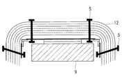
- a detachable mounting means for the multilayer heat insulating material For example, as shown in FIG. 12, there is known a method of attaching a multilayer thermal insulator (thermal blanket) 102 to a mounting surface using a surface fastener 104 or the like.
- Patent Document 1 below discloses a method of attaching a thermal blanket to a mounting surface using a surface fastener (Velcro (registered trademark) tape).
- the multilayer heat insulating material causes a heat leak due to heat conduction at that portion, which causes the heat insulating performance to be deteriorated.
- Such crimped points tend to occur around the mounting means of the multilayer insulation.
- the conventional hook-and-loop fastener 104 is used as a mounting means, the multi-layered heat insulating material 102 is sewn to the hook-and-loop fastener 104 by the suture thread 103. Crimping of 102b will occur.
- the multilayer heat insulating material 102 is formed by being laminated with the spacer 102 b interposed between the heat insulating sheets 102 a, so it is difficult to handle as it is separated as it is.
- it is integrated by sewing in order to make it easy to handle, it becomes difficult to deform it into a desired shape.
- the spacecraft-mounted device is covered, it may not be easy to deform at a predetermined location along the three-dimensional shape.
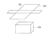
- FIG. 13 it is possible to easily bend the target object 109 to be attached at a predetermined location by sewing in advance a line to be a crease to form a stitched portion.
- the heat insulating sheet 102a and the spacer 102b are crimped at the seamed portion, resulting in deterioration of the heat insulating performance.
- the present invention has been made in view of such circumstances, and it is an object of the present invention to provide a multilayer heat insulating material which suppresses the deterioration of the heat insulating performance around the mounting means and facilitates the deformation to a desired shape. Do.
- a multilayer heat insulating material includes a heat insulating member in which a heat insulating sheet and a spacer are stacked, a locking sheet provided adjacent to the heat insulating member, the heat insulating member and the lock A heat insulating member stop which penetrates and locks the seat for the seat, and a mounting member which is provided on the stop sheet and which is attachable to and detachable from an object to be mounted; And locking the respective layers of the heat insulating member so as not to be in close contact with each other.
- the heat insulating member and the locking sheet are locked by the heat insulating member locking tool such that the heat insulating sheet and the spacer are not in close contact with each other.
- the heat insulating member and the locking sheet are detachably attached to the mounting object by the mounting member provided on the locking sheet. Since the mounting member is provided on the locking sheet, it is not directly attached to the heat insulating member. And since the heat insulating member stopper is locked so that the layers of the heat insulating member do not contact closely, it is possible to prevent the deterioration of the heat insulating performance due to the contact of the layers of the heat insulating member.
- the heat insulating member locking device is provided at a shaft portion penetrating the heat insulating member and the locking sheet in the stacking direction, and at both ends of the shaft portion And a length of the shaft portion is longer than a thickness when the heat insulating member and the locking sheet are brought into contact in a state where no load is applied. .
- the layers of the heat insulating member are not brought into close contact by making the length of the shaft portion of the heat insulating member locking tool longer than the thickness when the heat insulating member and the locking sheet are in contact with each other without load applied. Can be locked.
- the locking sheet is a mesh or porous sheet.
- the locking sheet is characterized by including a bent portion in which a bending line can be formed along a predetermined direction.
- a bending portion is provided on the locking sheet, and a bending line is formed along a predetermined direction. Thereby, a multilayer heat insulating material can be mounted according to the shape of the mounting target.
- the locking sheet includes a plurality of locking sheet pieces and a sheet connection portion that connects the locking sheet pieces, and the bending is performed.
- the part is formed by the sheet connection part.
- the locking sheet is divided into a plurality of locking sheet pieces, and a sheet connection portion for connecting the locking sheet pieces is provided.
- the sheet connection portion forms a bent portion.
- a sheet seat connection part, an adhesive tape, a resin film, etc. are mentioned, for example.
- the plurality of locking sheet pieces are characterized in that they have shapes corresponding to the respective surfaces of the mounting object.
- the multilayer heat insulating material can be mounted according to the shape of the mounting object.
- Deterioration of the heat insulating performance around the mounting means of the multilayer heat insulating material can be suppressed, and deformation to a desired shape can be facilitated.
- FIG. 2 is a cross-sectional view taken along the line A-A ′ of FIG.
- FIG. 2 is a cross-sectional view taken along the line A-A ′ of FIG.
- the manufacturing method of the multilayer heat insulating material which concerns on 1st Embodiment of this invention it is a figure which shows latching of the laminated body by insertion of a heat insulating material latching tool.
- the manufacturing method of the multilayer heat insulating material which concerns on 1st Embodiment of this invention it is a figure which shows stitching
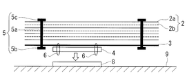
- the multilayer heat insulating material 1 according to the present embodiment is fastened to the heat insulating member 2, the locking sheet 3 provided adjacent to the heat insulating member, and the locking sheet 3, as shown in FIGS. 1 and 2.
- the mounting member 4 and the heat insulating member fastener 5 are provided.
- the heat insulating member 2 is formed by stacking 10 to 20 layers of the heat insulating sheet 2a with the spacer 2b interposed.
- An example of a thermal insulation sheet is a low emissivity film, such as a metal film deposited on a 10-20 micrometer thick resin film.
- a metal film deposited on a 10-20 micrometer thick resin film.
- a metal Al, Ag, Au, etc.
- Kapton film having a thickness of 10 to 20 micrometers can be mentioned.
- a mounting object 9 such as a rocket or a spacecraft such as an artificial satellite, or a device mounted on a spacecraft
- a mounting object 9 such as a rocket or a spacecraft such as an artificial satellite, or a device mounted on a spacecraft
- the spacer 2b a net-like member made of a heat insulating material or a porous sheet-like member can be mentioned, and in particular, one made of a material having a thermal conductivity lower than that of the film used for the heat insulating sheet 2a is preferable.
- the locking sheet 3 is fastened by the mounting member 4 and the suture thread 6.
- the mounting member 4 is used when mounting the multilayer heat insulating material 1 to the mounting object 9.
- the mounting member 8 is provided on the surface of the mounting object 9 and the mounting member 4 is mounted on the mounting member 8.
- the mounting member 4 is not fastened to the heat insulating member 2.
- the mounting member 4 is preferably a mounting means that can be repeatedly removed, and in particular it is desirable that the mounting member 4 can be removed by an operation from the outside of the multilayer heat insulating material 1.
- An example of the mounting member 4 is a hook and loop fastener, but fasteners such as snaps and hooks can also be used.
- the locking sheet 3 can be repeatedly attached to and detached from the spacecraft and devices mounted on the spacecraft.
- the locking sheet 3 has such a strength that it does not break even if it is repeatedly attached and detached.
- Preferred examples of the locking sheet 3 include styrene, polyethylene, polypropylene, polytetrafluoroethylene, and sheets obtained by processing these foams.
- Other suitable examples of the locking sheet 3 include a reticulated sheet or a porous sheet made of styrene, polyethylene, polypropylene, polytetrafluoroethylene.
- the heat insulating member fasteners 5 are dispersedly provided in the in-plane direction of the laminate including the heat insulating member 2 and the locking sheet 3.
- the heat insulating member stopper 5 includes a shaft 5 a and a pair of locking parts 5 b and 5 c provided at both ends of the shaft 5 a.
- the locking portion 5b is provided on the outside of the locking sheet 3 of the laminated body, and the locking portion 5c is provided on the outside of the heat insulating member 2 of the laminated body.
- a tag pin attached by a tag gun is raised.
- Examples of the material of the heat insulating member stopper 5 include nylon.
- the shaft 5 a is provided so as to penetrate the layers (the heat insulating sheet 2 a and the spacer 2 b stacked) and the locking sheet 3 of the heat insulating member 2.
- the heat insulating member locking tool 5 is formed such that the length of the shaft portion 5 a is equal to or more than the sum of the thickness of the heat insulating member 2 formed by laminating and the thickness of the locking sheet 3. For this reason, the interlayer distance of each layer of the heat insulating member 2 is not narrowed by the heat insulating member locking tool 5 without being greatly narrowed. Therefore, the heat insulation performance does not deteriorate due to the pressure bonding of each layer of the heat insulation member.
- the sum of the thickness of the heat insulating member 2 formed by lamination and the thickness of the locking sheet 3 is the thickness when the heat insulating member is in contact in a state where no load is applied, ie, the heat insulating member 2 It means the thickness of the state where and and the seat 3 for locking overlap by dead weight.
- the shaft portion 5a does not restrain the layers of the heat insulating member 2 and the locking sheet 3 in the stacking direction in the penetrating portion of the laminate, and the shaft portion 5a and the layers of the heat insulating member 2 and the locking sheet 3 are of the shaft portion 5a.
- the relative position can be changed in the extending direction.
- the locking portions 5b and 5c are each formed so as to have a portion longer than the diameter of the hole formed in the through portion of the laminate through which the shaft portion 5a passes in a direction intersecting the shaft portion 5a.
- the locking portions 5b and 5c are each rod-like or plate-like, and are connected to the shaft 5a at central portions in the respective longitudinal directions, and are longer than the diameter of the hole in the direction intersecting the shaft 5a from the connecting portion To extend. This prevents the heat insulating member stopper 5 from falling out of the laminate.
- the locking portions 5b and 5c are each formed of a material and in a shape such that the locked state can be maintained even when a force is applied to the heat insulating member locking tool 5 when the multilayer heat insulating material 1 is attached and detached.
- the heat insulating member fasteners 5 are dispersedly provided in the surface direction of the laminate. For example, as shown in FIG. 1, they are provided dispersedly at the four corners of the laminate.
- each layer of the heat insulating member 2 It is possible to suppress the decrease in heat insulation performance due to the pressure bonding of
- a spacer 2 b is interposed between the heat insulating sheet 2 a and the heat insulating sheet 2 a, and a predetermined number of sheets are stacked to form the heat insulating member 2.
- the heat insulating sheet 2a is formed, for example, by forming a film in which metal is vapor-deposited on a resin film such as Kapton, in a predetermined shape.
- the locking sheet 3 is placed adjacent to the heat insulating member 2 to form a laminate.
- the heat insulating member 2 is placed on the locking sheet 3 so that the lower surface of the heat insulating member 2 and the upper surface of the locking sheet 3 are adjacent to each other.
- the mounting member 4 is fastened to the locking sheet 3 by sewing or the like.
- the mounting member 4 is fastened to the opposite side of the surface where the locking sheet 3 is adjacent to the heat insulating member 2.
- the heat insulating member stopper 5 is inserted from the upper surface of the heat insulating member 2 of the laminate so as to penetrate the layers of the heat insulating member 2 and the locking sheet 3.
- a tag pin is used as the heat insulating member stopper 5, and the tag pin is inserted from the upper surface of the heat insulating member 2 using a tag gun.
- insertion may be made while forming a through hole in the heat insulating member 2 and the locking sheet 3, or in the case where a hole is formed in advance in at least a part of the heat insulating member 2 and the locking sheet 3. May be inserted through the holes and through them.
- the inserted heat insulating member locking tool 5 penetrates the heat insulating member 2 and the locking sheet 3 and then, below the locking sheet 3, the locking portion 5b is centered on the connecting portion with the shaft portion 5a, It deforms into a shape extending longer than the diameter of the hole in the direction intersecting the shaft 5a from the connection.
- the heat insulating member 2 and the locking sheet 3 are locked so that the heat insulating member locking tool 5 does not fall out of the laminated body.
- the locking portion 5b is folded so as to be substantially parallel to the shaft portion 5a.
- the heat insulating member 2 is fixed by being inserted into the heat insulating member 2 and the locking sheet 3 so as to penetrate, and then the fixed state is released below the locking sheet 3.
- the shape may be recovered by elasticity, and the heat insulating member 2 and the locking sheet 3 may be locked.
- each layer of the laminated body can slide on the shaft portion 5a and can be easily deformed into a desired shape.
- Steps 1-3 and 1-4 described above are repeated, and the heat insulating member 2 is locked to the locking sheet 3 by providing a predetermined number of the heat insulating member fasteners 5 in a distributed manner in the surface direction of the laminate. And integrate the multi-layered heat insulating material 1.
- the heat insulating member 2 has a polygonal shape in plan view
- one or more heat insulating member fasteners 5 may be dispersedly provided in the vicinity of each vertex, or the sides of the polygon may be provided. It may be provided in the peripheral part in a distributed manner along a part or all of.
- the integrated multi-layered heat insulating material 1 is mounted on the mounting object 9 through the mounting member 4 fastened to the locking sheet 3 and the mounting member 8.
- the mounting member 4 and the mounting member 8 appropriately select the position and the number according to the shape of the mounting object 9.
- the mounting object is a rocket tank
- the pairs of mounting members 4 and mounting members 8 are formed in consideration of the required shape of the multilayer heat insulating material 1 and the direction of stress applied during flight. It should be arranged.
- Step 1-1 As shown in FIG. 4, after the heat insulating sheet 2a and the spacer 2b are stacked to form the heat insulating member 2, the step of sewing and integrating the peripheral portion is further provided. Good (step 1-1 '). Thereby, the handleability at the time of manufacturing the multilayer heat insulating material 1 can be improved. In this step, it is preferable that the heat insulating member 2 be formed larger than the locking sheet 3 and the peripheral edge to be sewn be extended outward from the locking sheet 3 in the surface direction.
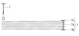
- the some heat insulation member peripheral part is formed in the peripheral part. It may further comprise the step of providing the fasteners 7 in a distributed manner and integrating them (step 1-1 ′ ′).
- the heat insulating member peripheral edge locking tool 7 is provided through the heat insulating member 2 and has a heat insulating member peripheral edge locking tool shaft 7 a having a length equal to or greater than the thickness of the heat insulating member 2 formed by stacking.
- the heat insulating member peripheral edge fastener 7 is inserted from the upper surface of the heat insulating member 2 so as to penetrate each layer of the heat insulating member 2, and the heat insulating member peripheral edge fastener is engaged below the heat insulating member 2.
- a shape in which the stop portion 7b extends longer than the diameter of the hole in the direction in which the stop portion 7b intersects the heat insulating member peripheral locking portion shaft portion 7a from the connecting portion centering on the connection portion with the heat insulating member peripheral portion locking shaft portion 7a Transform into This is repeated, and the heat insulating member 2 is integrated by dispersing and providing a predetermined number of heat insulating member peripheral edge fasteners 7 in the surface direction of the heat insulating member 2.
- the length of the heat insulating member peripheral portion engaging tool shaft 7a is longer than the thickness of the heat insulating member 2 formed by laminating, even if the heat insulating member 2 is integrated by the heat insulating member peripheral edge engaging member 7, the heat insulating member There is no need to greatly reduce the distance between the two layers. Thereby, the handleability can be improved without deteriorating the heat insulating performance due to the close contact of the layers of the heat insulating member 2.
- the heat insulation member peripheral part latching tool 7 you may make it insert in the heat insulation member 2 by the same means as the heat insulation member fastener 5 using the same thing as the above-mentioned heat insulation member fastener 5.
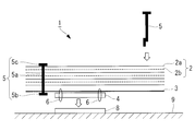
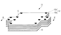
- the multilayer heat insulating material 11 which concerns on this embodiment is shown in FIG. 6 thru
- the multilayer heat insulating material 11 according to the present embodiment is fastened to the heat insulating member 12, the locking sheet 13 provided adjacent to the heat insulating member 12, and the locking sheet 13, as shown in FIGS. Mounting member 4 and the heat insulating member fastener 5.
- the laminated body consisting of the heat insulating member 12 and the locking sheet 13 is integrated by the heat insulating member locking tool 5.
- the locking sheet 13 includes a plurality of locking sheet pieces 13a and a flexible sheet connecting portion (bending portion) 13b that connects the plurality of locking sheet pieces.
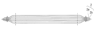
- the locking sheet 13 has at least a part of a surface constituting a developed view in which a predetermined three-dimensional shape 13 ′ surrounding the mounting object 9 is developed. That is, each locking sheet piece 13 a has a shape corresponding to each surface of the mounting object 9. Specifically, it has a shape that can form a predetermined three-dimensional shape 13 ′ surrounding the mounting object 9 by bending the locking sheet 13 at the sheet connection portion 13 b.
- the locking sheet 13 shown in FIG. 11 does not have a portion corresponding to the bottom surface and is shaped to cover the mounting object 9 from above, it is also configured to have the bottom surface and cover the entire mounting object 9 Good.
- the locking sheet piece 13a is made of, for example, styrene, polyolefin, polypropylene, polytetrafluoroethylene or the like, and is a sheet piece on a flat plate having rigidity.
- the multi-layered heat insulating material 11 is deformed along the shape of the mounting object 9, the shape of the locking sheet 13 is maintained, and the locking portions 5b and 5c of the heat insulating member locking tool 5 are not broken. It is desirable to determine the thickness and material so that it can be locked.
- Each of the locking sheet pieces 13a has at least one shape of surfaces constituting a developed view in which a predetermined three-dimensional shape 13 'surrounding the mounting object 9 is developed. The thickness and material of the locking sheet 13 may be locally changed.
- the sheet connection portion 13b is a flexible material that connects the peripheral edge portion and the peripheral edge portion of the locking sheet piece 13a, and connects the locking sheet piece 13a so that the relative position can be deformed.
- the sheet connection portion 13 b is formed more flexibly than the locking sheet piece 13 a having rigidity. Thereby, when making the multilayer heat insulating material 11 deform
- the sheet connecting portion 13 b preferably has a structure in which the sheet connecting portion 13 b is bonded to the inside in the bending direction of the locking sheet 13.
- the heat insulating member 12 is formed by overlapping 10 to 20 layers of the heat insulating sheet 12 a with the spacer 12 b interposed therebetween.
- the heat insulating member 12 is larger than the locking sheet 13 in plan view, and has a shape that covers the entire locking sheet in a state where the locking sheet 13 is bent inward.
- the peripheral shape of the locking sheet 13 is substantially the same as the locking sheet 13 and extends outward from the locking sheet in the surface direction.
- the multi-layered heat insulating material 11 is bent at the sheet connection portion 13 b and deformed along the shape of the mounting object 9, no gap is generated and the pressure bonding of each layer of the heat insulating member 12 is performed.
- the object to be mounted can be covered with the heat insulating member 12 without causing the deterioration of the heat insulating performance due to the above.
- the peripheral portions of the heat insulating member 12 may be in abutment or may be in an overlapping state.
- the heat insulating member fasteners 5 are dispersedly provided in the in-plane direction of the laminate including the heat insulating member 12 and the locking sheet 13.
- the shaft portion 5 a of the heat insulating member locking tool 5 is provided so as to penetrate through the layers (the stacked heat insulating sheet 12 a and the spacer 12 b) of the heat insulating member 12 and the locking sheet 13.
- the heat insulating member locking tool 5 is formed such that the length of the shaft portion 5 a is equal to or more than the sum of the thickness of the heat insulating member 12 formed by stacking and the thickness of the locking sheet 13.
- the interlayer distance of each layer of the heat insulating member 2 is not greatly narrowed by the heat insulating member fastener 5, and hence the heat insulating performance is not deteriorated due to the pressure bonding of each layer of the heat insulating member.
- the sum of the thickness of the heat insulating member 12 formed by laminating and the thickness of the locking sheet 13 is the thickness when the heat insulating member is in contact with no load applied, ie, the heat insulating member 12 It means the thickness of the state where and and the seat 13 for locking overlap by dead weight.
- the length of the shaft 5a may be locally changed beforehand in advance.
- the shaft portion 5a does not restrain the layers of the heat insulating member 12 and the locking sheet 13 in the stacking direction in the penetrating portion of the laminate, and the shaft portion 5a and the layers of the heat insulating member 12 and the locking sheet 13 are of the shaft portion 5a.
- the relative position can be changed in the extending direction.
- the locking portions 5b and 5c are each formed so as to have a portion longer than the diameter of the hole formed in the through portion of the laminate through which the shaft portion 5a passes in a direction intersecting the shaft portion 5a. There is.
- the locking portions 5b and 5c are each rod-like or plate-like, and are connected to the shaft 5a at central portions in the respective longitudinal directions, and are longer than the diameter of the hole in the direction intersecting the shaft 5a from the connecting portion To extend.
- the locking portions 5b and 5c are each formed of a material and in a shape such that the locked state can be maintained even when a force is applied to the heat insulating member locking tool 5 when the multilayer heat insulating material 11 is attached and detached.
- the heat insulating member fasteners 5 be dispersedly provided in the surface direction so as to penetrate the peripheral portion of the fastening sheet piece 13a.
- the position where the heat insulating member locking tool 5 is provided is determined on the assumption that the locking sheet 13 is bent at the sheet connecting portion 13 b to form a predetermined three-dimensional shape 13 ′ surrounding the object 9 to be mounted.
- the heat insulating member fasteners 5 are provided at the four corners of the locking sheet piece 13 a corresponding to the top plate of the three-dimensional shape 13 ′.
- the locking sheet piece 13a corresponding to the top plate of the three-dimensional shape 13 ' is located at the center of bending the locking sheet 13 at the sheet connection portion 13b, and the positional variation at the time of bending is small.
- the variation in the relative position between each layer of the heat insulating member 12 and the locking sheet 13 is a small part. Therefore, the heat insulating member is efficiently fixed by fixing the relative position with the locking sheet 13 by first providing the heat insulating member locking tool 5 at the four corners of the locking sheet piece 13a corresponding to the top plate of the three-dimensional shape 13 '. 12 can be locked to the locking sheet 13.
- the heat insulating member fasteners 5 are also provided on the peripheral portions (peripheral portions on the opposite side of the sheet connection portion 13b) of the respective locking sheet pieces 13a connected at the peripheral portions.
- the multilayer heat insulating material can be integrated regardless of the change of the relative position at the time of bending.
- each locking sheet piece 13a is formed into a shape as shown in FIG. 11 based on the shape of each surface constituting this developed view.
- the locking sheet piece 13a maintains the shape and is not broken It selects so that the latching
- the peripheral edge portions of the respective locking sheet pieces 13a are connected by the sheet connecting portion 13b so as to form a developed view (see FIG. 7), and the locking sheet 13 is formed.
- the locking sheet 13 is adhered to the peripheral portion of the locking sheet piece 13a from the inner side when the locking sheet 13 is bent.
- the mounting member 4 is fastened to the locking sheet 13 by sewing or the like.
- the mounting member 4 is fastened to the locking sheet piece 13a positioned at the center when the locking sheet 13 is folded.
- the plurality of attachment members 4 may be attached to the plurality of locking sheet pieces 13 a for attachment of the multilayer heat insulating material.
- a predetermined number of sheets are laminated by interposing the spacer 12b between the heat insulating sheet 12a and the heat insulating sheet 12a.
- the heat insulation member 12 is formed.
- the heat insulating sheet 12a is formed by, for example, forming a film in which metal is vapor-deposited on a resin film such as Kapton, in a predetermined shape.
- the shape of the heat insulating sheet 12 a is substantially the same as the shape of the locking sheet 13, and the peripheral edge portion of the heat insulating sheet 12 a extends outward in the plane direction from the locking sheet.
- the locking sheet 13 is placed adjacent to the heat insulating member 12 to form a laminate.
- the heat insulating member 12 is placed on the locking sheet 13 so that the lower surface of the heat insulating member 12 and the upper surface of the locking sheet 13 are adjacent to each other.
- the mounting member 4 is disposed on the opposite side of the surface where the locking sheet 13 is adjacent to the heat insulating member 12.
- each layer of the heat insulating member 12 and the locking sheet 13 from the upper surface of the heat insulating member 12 of the laminate are inserted so as to penetrate the
- a tag pin is used as the heat insulating member stopper 5, and the tag pin is inserted from the upper surface of the heat insulating member 12 using a tag gun.
- insertion may be made while forming a through hole in the heat insulating member 12 and the locking sheet 13, or in the case where a hole is formed in advance in at least a part of the heat insulating member 12 and the locking sheet 13. May be inserted through the holes and through them.
- the inserted heat insulating member locking tool 5 penetrates the heat insulating member 12 and the locking sheet 13 and then, below the locking sheet 13, the locking portion 5b is centered on the connecting portion with the shaft portion 5a, It deforms into a shape extending longer than the diameter of the hole in the direction intersecting the shaft 5a from the connection. As a result, the heat insulating member locking tool 5 is locked from the laminated body so that the heat insulating member 12 and the locking sheet 13 are locked.
- the shaft portion 5a By forming the shaft portion 5a to have a smooth surface shape in the extension direction of the shaft portion, each layer of the laminated body can slide on the shaft portion 5a and can be easily deformed into a desired shape. (Step 2-5)
- Steps 2-4 and 2-5 are repeated, and the heat insulating member 12 is locked to the locking sheet 13 by dispersing the predetermined number of heat insulating member fasteners 5 in the surface direction of the laminate.
- the multi-layered heat insulating material 11 is integrated.
- the heat insulating member stoppers 5 are provided at the four corners of the locking sheet piece 13a corresponding to the top plate of the three-dimensional shape 13 ', and further, the peripheral portions of the respective locking sheet pieces 13a connected by the peripheral portion
- the heat insulating member stopper 5 is also provided on the (peripheral portion on the opposite side to the sheet connection portion 13b).
- the heat insulating member stopper 5 is provided, assuming that the outer layer of the heat insulating member 12 has a larger radius of curvature than the inner layer when the locking sheet 13 is bent in a shape convex outward at the inner side. Decide.
- the heat insulating member fasteners 5 are provided in the substantially vertical direction (stacking direction) at the four corners of the fastening sheet piece 13a corresponding to the top plate of the three-dimensional shape 13 ′.
- the heat insulating member stopper 5 ′ having the longer shaft portion 5 a ′ is disposed in the stacking direction so as to penetrate the position (a spaced position) advanced from the bending planned position toward the outer layer. It is installed diagonally.
- heat insulation member fastener 5 ' is extended in the part extended from a bending plan position. It may be provided substantially vertically.
- the integrated multi-layered heat insulating material 11 is mounted on the mounting object 9 by connecting the mounting member 4 fastened to the locking sheet 13 and the mounting member 8 on the other side. At the time of mounting, the multi-layer heat insulating material 11 is deformed according to the shape of the mounting object 9 by bending the locking sheet 13 so as to form a predetermined three-dimensional shape 13 ′. The mounting member 4 and the mounting member 8 appropriately select the position and the number according to the shape of the mounting object 9.
- the peripheral portions are sewn together It may further comprise the step of integrating (step 2-2 ').
- the step of integrating it is preferable that the heat insulating member 12 be formed larger than the locking sheet 13 and the peripheral edge to be sewn be extended outward from the locking sheet 13 in the surface direction.
- the portion extending from the locking sheet may be cut out together with the sewn portion. In this case, the contact state of each layer of the heat insulating member caused by the sewed peripheral portion is alleviated.
- the heat insulating member peripheral portion fastener 7 may be provided in a distributed manner and integrated (step 2-2 ′ ′).
- the heat insulating member peripheral edge locking member 7 is inserted from the upper surface of the heat insulating member 12 so as to penetrate each layer of the heat insulating member 12, and the heat insulating member peripheral edge locking member locking portion 7 b is below the heat insulating member 2.
- the heat insulating member 2 is integrated by dispersing and providing a predetermined number of heat insulating member peripheral edge fasteners 7 in the surface direction of the heat insulating member 2.
- the heat insulating member peripheral edge engaging member 7 the same one as the above-described heat insulating member engaging member 5 may be used, and the heat insulating member engaging member 5 may be inserted into the heat insulating member 12 by the same means.
- the locking sheet 13 is not divided, You may make a line which becomes a crease by a cut and a hollow.
Landscapes
- Engineering & Computer Science (AREA)
- Mechanical Engineering (AREA)
- Physics & Mathematics (AREA)
- Thermal Sciences (AREA)
- Health & Medical Sciences (AREA)
- Critical Care (AREA)
- Emergency Medicine (AREA)
- General Health & Medical Sciences (AREA)
- Remote Sensing (AREA)
- Aviation & Aerospace Engineering (AREA)
- General Engineering & Computer Science (AREA)
- Thermal Insulation (AREA)
Priority Applications (2)
| Application Number | Priority Date | Filing Date | Title |
|---|---|---|---|
| US16/498,096 US20200094996A1 (en) | 2017-06-09 | 2018-06-04 | Multilayer heat-insulating material |
| EP18813436.5A EP3587890A4 (en) | 2017-06-09 | 2018-06-04 | MULTI-LAYER THERMAL INSULATION MATERIAL |
Applications Claiming Priority (2)
| Application Number | Priority Date | Filing Date | Title |
|---|---|---|---|
| JP2017-114553 | 2017-06-09 | ||
| JP2017114553A JP6862289B2 (ja) | 2017-06-09 | 2017-06-09 | 多層断熱材 |
Publications (1)
| Publication Number | Publication Date |
|---|---|
| WO2018225688A1 true WO2018225688A1 (ja) | 2018-12-13 |
Family
ID=64565820
Family Applications (1)
| Application Number | Title | Priority Date | Filing Date |
|---|---|---|---|
| PCT/JP2018/021380 Ceased WO2018225688A1 (ja) | 2017-06-09 | 2018-06-04 | 多層断熱材 |
Country Status (4)
| Country | Link |
|---|---|
| US (1) | US20200094996A1 (enExample) |
| EP (1) | EP3587890A4 (enExample) |
| JP (1) | JP6862289B2 (enExample) |
| WO (1) | WO2018225688A1 (enExample) |
Families Citing this family (5)
| Publication number | Priority date | Publication date | Assignee | Title |
|---|---|---|---|---|
| CN111891408A (zh) * | 2020-06-30 | 2020-11-06 | 北京空间飞行器总体设计部 | 一种用于航天器增加隔热效果的多层隔热组件系统 |
| CN112208802B (zh) * | 2020-09-09 | 2022-07-12 | 航天科工空间工程发展有限公司 | 一种多层隔热组件 |
| CN112265862B (zh) * | 2020-10-26 | 2024-05-31 | 徐正强 | 一种保温棉及同类产品的折叠使用结构 |
| CN113071718B (zh) * | 2021-02-26 | 2023-06-02 | 北京空间飞行器总体设计部 | 月面起飞上升器热防护装置及其隔热性能计算方法 |
| EP4402706A4 (en) | 2022-08-05 | 2025-01-22 | Zenno Astronautics Limited | IMPROVED SATELLITE SYSTEM |
Citations (6)
| Publication number | Priority date | Publication date | Assignee | Title |
|---|---|---|---|---|
| JPH04134000U (ja) * | 1991-06-03 | 1992-12-14 | 日本電気エンジニアリング株式会社 | サーマルブランケツト |
| JPH09152088A (ja) | 1995-12-04 | 1997-06-10 | Nec Eng Ltd | サーマルブランケット |
| JP2000072100A (ja) * | 1998-08-27 | 2000-03-07 | Ishikawajima Harima Heavy Ind Co Ltd | 多層断熱材の接地構造 |
| JP2007210618A (ja) * | 2006-02-07 | 2007-08-23 | Sekisui Plastics Co Ltd | 断熱性カバーとそれを用いた物品の保管方法および配送方法 |
| JP2013238305A (ja) * | 2012-05-17 | 2013-11-28 | Nagoya Oil Chem Co Ltd | 保温保冷吸音材 |
| JP2017078470A (ja) * | 2015-10-21 | 2017-04-27 | 株式会社トスカバノック | 断熱材の構造と断熱材の止着固定方法及びその構造 |
Family Cites Families (13)
| Publication number | Priority date | Publication date | Assignee | Title |
|---|---|---|---|---|
| JPS6135832U (ja) * | 1984-08-03 | 1986-03-05 | 積水化成品工業株式会社 | 合成樹脂製積層断熱材 |
| JPH056115Y2 (enExample) * | 1988-02-26 | 1993-02-17 | ||
| GB9020428D0 (en) * | 1990-09-19 | 1990-10-31 | Gore W L & Ass Uk | Thermal control materials |
| AUPP483298A0 (en) * | 1998-07-23 | 1998-08-13 | Bains Harding Limited | Insulation module for vessels |
| JP4155347B2 (ja) * | 1998-09-04 | 2008-09-24 | Necエンジニアリング株式会社 | サーマルブランケットの電気的導通加工方法 |
| JP2002337800A (ja) * | 2001-05-21 | 2002-11-27 | Nec Corp | サーマルブランケット |
| JP4261966B2 (ja) * | 2003-04-16 | 2009-05-13 | Nbc株式会社 | エアコン室外機遮熱用カバー |
| JP4549909B2 (ja) * | 2005-03-25 | 2010-09-22 | 三菱電機株式会社 | 人工衛星用のサーマルブランケットおよびその取付方法 |
| JP2008082039A (ja) * | 2006-09-28 | 2008-04-10 | Mimo Material Kk | 断熱材 |
| JP5351112B2 (ja) * | 2009-09-02 | 2013-11-27 | ニチアス株式会社 | 断熱材 |
| JP2012132494A (ja) * | 2010-12-21 | 2012-07-12 | Ihi Aerospace Co Ltd | 多層断熱材 |
| JP2014184875A (ja) * | 2013-03-25 | 2014-10-02 | Mitsubishi Electric Corp | 多層断熱材 |
| CN106626676A (zh) * | 2017-01-23 | 2017-05-10 | 江苏泛亚微透科技股份有限公司 | 绝热隔音气凝胶层复合透气膜的复合材料及其制造方法 |
-
2017
- 2017-06-09 JP JP2017114553A patent/JP6862289B2/ja not_active Expired - Fee Related
-
2018
- 2018-06-04 WO PCT/JP2018/021380 patent/WO2018225688A1/ja not_active Ceased
- 2018-06-04 US US16/498,096 patent/US20200094996A1/en not_active Abandoned
- 2018-06-04 EP EP18813436.5A patent/EP3587890A4/en not_active Withdrawn
Patent Citations (6)
| Publication number | Priority date | Publication date | Assignee | Title |
|---|---|---|---|---|
| JPH04134000U (ja) * | 1991-06-03 | 1992-12-14 | 日本電気エンジニアリング株式会社 | サーマルブランケツト |
| JPH09152088A (ja) | 1995-12-04 | 1997-06-10 | Nec Eng Ltd | サーマルブランケット |
| JP2000072100A (ja) * | 1998-08-27 | 2000-03-07 | Ishikawajima Harima Heavy Ind Co Ltd | 多層断熱材の接地構造 |
| JP2007210618A (ja) * | 2006-02-07 | 2007-08-23 | Sekisui Plastics Co Ltd | 断熱性カバーとそれを用いた物品の保管方法および配送方法 |
| JP2013238305A (ja) * | 2012-05-17 | 2013-11-28 | Nagoya Oil Chem Co Ltd | 保温保冷吸音材 |
| JP2017078470A (ja) * | 2015-10-21 | 2017-04-27 | 株式会社トスカバノック | 断熱材の構造と断熱材の止着固定方法及びその構造 |
Non-Patent Citations (1)
| Title |
|---|
| See also references of EP3587890A4 |
Also Published As
| Publication number | Publication date |
|---|---|
| EP3587890A1 (en) | 2020-01-01 |
| JP2018204781A (ja) | 2018-12-27 |
| EP3587890A4 (en) | 2021-01-20 |
| JP6862289B2 (ja) | 2021-04-21 |
| US20200094996A1 (en) | 2020-03-26 |
Similar Documents
| Publication | Publication Date | Title |
|---|---|---|
| WO2018225688A1 (ja) | 多層断熱材 | |
| US7954301B2 (en) | Integrated multilayer insulation | |
| WO1999061719A1 (en) | Laminate bulkhead with flared edges | |
| EP3196113B1 (en) | Barrier structure for corner portion of cargo hold and method for installing barrier for corner portion of cargo hold | |
| US8424463B2 (en) | Interior structure for railway vehicle | |
| US20210046725A1 (en) | Core material for composite structures | |
| US10183702B2 (en) | Sidewall assembly for trailers | |
| JP6238168B2 (ja) | 複合材構造 | |
| US20170349297A1 (en) | Structural composite component and method for configuring a structural composite component | |
| US10819094B2 (en) | Protector-equipped electric wire and protector-equipped wire arrangement structure | |
| EP2707606B1 (en) | Connecting device, assembly and method for manufacturing an assembly | |
| EP3336405B1 (en) | Heat insulation structure | |
| CN112208802B (zh) | 一种多层隔热组件 | |
| US20170136728A1 (en) | Composite material structure | |
| JP2023010995A (ja) | 配線部材 | |
| JPH07229999A (ja) | 遮蔽用鉛板積層マット | |
| JP2019098926A (ja) | 宇宙機の熱制御用被覆部材 | |
| EP3581842B1 (en) | Heat insulation structure | |
| US20250276778A1 (en) | Flat bulkheads, an aircraft, and a method of producing a flat bulkhead | |
| US20250369468A1 (en) | Mli fastening system | |
| JP4388430B2 (ja) | Icチップ実装体 | |
| US9610658B2 (en) | Reel feed clinching tack pins | |
| CN119957812A (zh) | 立式罐 | |
| JP6244166B2 (ja) | 積層部材およびその製造方法 | |
| JP2005059793A (ja) | 太陽電池の取付方法および連結構造 |
Legal Events
| Date | Code | Title | Description |
|---|---|---|---|
| 121 | Ep: the epo has been informed by wipo that ep was designated in this application |
Ref document number: 18813436 Country of ref document: EP Kind code of ref document: A1 |
|
| ENP | Entry into the national phase |
Ref document number: 2018813436 Country of ref document: EP Effective date: 20190925 |
|
| NENP | Non-entry into the national phase |
Ref country code: DE |