WO2018225643A1 - 視野角制御体及びその製造方法、並びに視野角制御画像表示体 - Google Patents
視野角制御体及びその製造方法、並びに視野角制御画像表示体 Download PDFInfo
- Publication number
- WO2018225643A1 WO2018225643A1 PCT/JP2018/021168 JP2018021168W WO2018225643A1 WO 2018225643 A1 WO2018225643 A1 WO 2018225643A1 JP 2018021168 W JP2018021168 W JP 2018021168W WO 2018225643 A1 WO2018225643 A1 WO 2018225643A1
- Authority
- WO
- WIPO (PCT)
- Prior art keywords
- light transmission
- viewing angle
- angle control
- average value
- transmission band
- Prior art date
- Legal status (The legal status is an assumption and is not a legal conclusion. Google has not performed a legal analysis and makes no representation as to the accuracy of the status listed.)
- Ceased
Links
Images



Classifications
-
- G—PHYSICS
- G09—EDUCATION; CRYPTOGRAPHY; DISPLAY; ADVERTISING; SEALS
- G09F—DISPLAYING; ADVERTISING; SIGNS; LABELS OR NAME-PLATES; SEALS
- G09F19/00—Advertising or display means not otherwise provided for
- G09F19/12—Advertising or display means not otherwise provided for using special optical effects
-
- G—PHYSICS
- G02—OPTICS
- G02B—OPTICAL ELEMENTS, SYSTEMS OR APPARATUS
- G02B5/00—Optical elements other than lenses
-
- G—PHYSICS
- G09—EDUCATION; CRYPTOGRAPHY; DISPLAY; ADVERTISING; SEALS
- G09F—DISPLAYING; ADVERTISING; SIGNS; LABELS OR NAME-PLATES; SEALS
- G09F9/00—Indicating arrangements for variable information in which the information is built-up on a support by selection or combination of individual elements
Definitions
- the present invention relates to a viewing angle control body that controls the viewing angle of an image displayed by an image display device or the like, a manufacturing method thereof, and a viewing angle control image display body that includes the viewing angle control body.
- an information input / output device including an image display device with a touch panel is widely used.
- the display surface of the image display device has the right and left sides without impairing the visibility from the front side.
- a sheet-like viewing angle control body for preventing peeping from the opposite side is provided.
- the viewing angle control body for preventing peeping includes a louver layer in which light transmission bands and light shielding bands are alternately provided, a transparent protective layer provided on one surface of the louver layer, and the other of the louver layers.
- a laminate in which a transparent adhesive layer provided on a surface is laminated is known (Patent Document 1).
- a louver layer that controls the viewing angle is known in which the width of the light transmission band is gradually changed to limit the viewing angle of the entire viewing angle control body (Patent Documents 2 and 3).
- the present invention is displayed in the end region of the display surface of the image display body while having an anti-peeping property even if the image displayed by an image display body such as an image display device is peeped.
- Another object of the present invention is to provide a viewing angle control body capable of ensuring the visibility of a captured image and a method for manufacturing the same.
- a sheet-like viewing angle control body including a louver layer in which a plurality of light transmission bands and light shielding bands are alternately provided, A first end region including one end portion of the viewing angle control body in the direction A along the surface direction of the viewing angle control body, and a second end including the other end portion of the viewing angle control body in the direction A. And a central region formed between the first end region and the second end region, The width along the direction A of the light transmission band provided in the first end region and the second end region is larger than the width along the direction A of the light transmission band provided in the central region. Wide viewing angle control body.
- the width of the light transmission band provided in the central region is 50 ⁇ m or more and 200 ⁇ m or less, and the width of the light transmission band provided in the first end region and the second end region is in the central region.
- a first intermediate region is provided between the first end region and the central region, and a second intermediate region is provided between the second end region and the central region.
- the width of the light transmission band provided in the intermediate region is narrower than the width of the light transmission band provided in the first end region and wider than the width of the light transmission band provided in the central region. 2
- the width of the light transmission band provided in the intermediate region is narrower than the width of the light transmission band provided in the second end region and wider than the width of the light transmission band provided in the central region,
- the viewing angle control body according to [1] or [2]. [5]
- the width of the light transmission band provided in the central region is 50 ⁇ m or more and 200 ⁇ m or less
- the width of the light transmission band provided in the first intermediate region is the width of the light transmission band provided in the central region.
- the width of the light transmission band provided in the first end region is 1 ⁇ m or more and 30 ⁇ m or less than the width of the light transmission band provided in the first intermediate region.
- the width of the light transmission band provided in the second intermediate region is made wider in the range of 1 ⁇ m to 30 ⁇ m than the width of the light transmission band provided in the central region, and the second end region is The viewing angle control body according to [4], wherein the width of the light transmission band provided is wider in the range of 1 ⁇ m to 30 ⁇ m than the width of the light transmission band provided in the second intermediate region.
- Control body [7] The viewing angle control body according to any one of [1] to [6], wherein the width of the light transmission band in each region is the same.
- the laminated body forming step includes a first laminated unit forming step of forming a first laminated unit by alternately laminating a plurality of first light transmitting band sheets and light shielding band sheets, and a first light transmitting band sheet.
- a second laminated unit forming step of forming a second laminated unit by alternately laminating a plurality of thin second light transmitting band sheets and light shielding band sheets; and a third light transmitting band thicker than the second light transmitting band sheet A second laminated unit between the first laminated unit and the third laminated unit, and a third laminated unit forming step of forming a third laminated unit by alternately laminating a plurality of sheets and a light shielding band sheet.
- the thickness of the second light transmission band sheet is 50 ⁇ m or more and 200 ⁇ m or less, and the thickness of the first light transmission band sheet and the thickness of the third light transmission band sheet are the second light transmission.
- the laminated body forming step includes alternately stacking a plurality of fourth light transmission band sheets and light shielding band sheets that are thinner than the first light transmission band sheet and thicker than the second light transmission band sheet.
- the thickness of the second light transmission band sheet is 50 ⁇ m or more and 200 ⁇ m or less, and the thickness of the fourth light transmission band sheet is 1 ⁇ m or more and 30 ⁇ m or less than the thickness of the second light transmission band sheet.
- the thickness of the first light transmission band sheet is increased in the range of 1 ⁇ m to 30 ⁇ m from the thickness of the fourth light transmission band sheet, and the thickness of the fifth light transmission band sheet is increased. Is made thicker in the range of 1 ⁇ m or more and 30 ⁇ m or less than the thickness of the second light transmission band sheet, and the thickness of the second light transmission band sheet is 1 ⁇ m or more and 30 ⁇ m larger than the thickness of the fifth light transmission band sheet.
- a viewing angle control image display body comprising an image display body and the viewing angle control body according to any one of [1] to [7] provided on the image display side of the image display body.
- the viewing angle control image display body according to [12] wherein secret information is displayed on the image display body, and a central region of the viewing angle control body is superimposed on the display of the secret information.
- a viewing angle control body including a louver layer in which a plurality of light transmission bands and a plurality of light shielding bands are alternately provided, A first end region including one end of a viewing angle control body in a direction A in which the plurality of light transmission bands and the plurality of light shielding bands are alternately provided; and a viewing angle control body in the direction A.
- a second end region including the other end, and a central region between the first end region and the second end region; The average value of the widths of the plurality of light transmission bands provided in the first end region and the second end region is larger than the average value of the widths of the plurality of light transmission bands provided in the central region.
- Wide viewing angle control body Wide viewing angle control body.
- the average value of the widths of the plurality of light transmission bands provided in the central region is 50 ⁇ m or more and 200 ⁇ m or less, and the plurality of lights provided in the first end region and the second end region.
- the first intermediate region includes a first intermediate region between the first end region and the central region, and a second intermediate region between the second end region and the central region.
- An average value of the widths of the plurality of light transmission bands provided in the first region is narrower than an average value of the widths of the plurality of light transmission bands provided in the first end region, and is provided in the central region.
- the average value of the widths of the plurality of light transmission bands provided in the second intermediate region is wider than the average value of the widths of the plurality of light transmission bands, and the plurality of light provided in the second end region.
- the viewing angle control body which is narrower than an average value of the width of the transmission band and wider than an average value of the widths of the plurality of light transmission bands provided in the central region.
- An average value of the widths of the plurality of light transmission bands provided in the central region is 50 ⁇ m or more and 200 ⁇ m or less
- an average value of the widths of the plurality of light transmission bands provided in the first intermediate region is The average value of the widths of the plurality of light transmission bands provided in the first end region, which is wider than the average value of the widths of the plurality of light transmission bands provided in the central region, in a range of 1 ⁇ m to 30 ⁇ m.
- Is wider in the range of 1 ⁇ m to 30 ⁇ m than the average value of the widths of the plurality of light transmission bands provided in the first intermediate region, and the width of the plurality of light transmission bands provided in the second intermediate region is The average value is wider in the range of 1 ⁇ m to 30 ⁇ m than the average width of the plurality of light transmission bands provided in the central region, and the width of the plurality of light transmission bands provided in the second end region.
- the average value of the plurality of light transmissions provided in the second intermediate region Wide by 30 ⁇ m or less the range of 1 ⁇ m than the average value of the width of the band, the viewing angle control element according to [4].
- the difference between the viewing angle of the first end region and the viewing angle of the central region is 15 ° or less
- the widths of the plurality of light transmission bands in the first end region are the same, The widths of the plurality of light transmission bands in the second end region are the same;
- the width of the central region is preferably 20% or more and 80% or less, and more preferably 30% or more and 60% or less, with respect to the entire length in the longitudinal direction of the viewing angle control body.
- the viewing angle control body according to any one of [7] to [7].
- the width of the first end region and the width of the second end region are preferably 10% or more and 40% or less, and 20% or more with respect to the total length in the longitudinal direction of the viewing angle control body.
- the viewing angle control body according to any one of [1] to [8], which is more preferably 35% or less.
- the average value of the widths of the plurality of light-shielding bands is preferably 1 ⁇ m or more and 50 ⁇ m or less, more preferably 10 ⁇ m or more and 30 ⁇ m or less, according to any one of [1] to [9]. Viewing angle control body.
- Forming a laminated body by alternately laminating a plurality of light transmission band sheets and a plurality of light shielding band sheets, pressurizing the laminated body to form a block body, and the block body And cutting along the direction in which the plurality of light transmission band sheets and the plurality of light shielding band sheets are alternately laminated, Forming the laminated body includes forming a first laminated unit by alternately laminating a plurality of first light transmitting band sheets and a plurality of first light shielding band sheets, and the first light transmitting band.
- a second laminated unit by alternately laminating a plurality of second light transmission band sheets and a plurality of second light shielding band sheets that are thinner than the sheet for the second sheet, and a plurality of thicker sheets than the second light transmission band sheet
- a third light transmission band sheet and a plurality of third light shielding band sheets are alternately laminated to form a third laminated unit, and the first laminated unit and the third laminated unit between the first laminated unit and the third laminated unit.
- the manufacturing method of the viewing angle control body including arrange
- An average value of the thicknesses of the plurality of second light transmission band sheets is 50 ⁇ m or more and 200 ⁇ m or less, and an average value of the thicknesses of the plurality of first light transmission band sheets and the plurality of third lights.
- Forming the laminated body further includes a plurality of fourth light transmission band sheets and a plurality of fourth light shielding sheets which are thinner than the first light transmission band sheet and thicker than the second light transmission band sheet.
- a plurality of fifth light transmission band sheets that are thinner than the third light transmission band sheet and thicker than the second light transmission band sheet; Alternately stacking a plurality of fifth light shielding strip sheets to form a fifth stacked unit, disposing the fourth stacked unit between the first stacked unit and the second stacked unit, Disposing the fifth stacked unit between the second stacked unit and the third stacked unit; and disposing the second stacked unit between the fourth stacked unit and the fifth stacked unit.
- the average value of the thickness of the plurality of second light transmission band sheets is 50 ⁇ m or more and 200 ⁇ m or less, and the average value of the thickness of the plurality of fourth light transmission band sheets is the plurality of second light beams. Thickness in the range of 1 ⁇ m or more and 30 ⁇ m or less than the average thickness of the transmission band sheet, and the average thickness of the plurality of first light transmission band sheets is the thickness of the plurality of fourth light transmission band sheets.
- the average value of the thicknesses of the plurality of fifth light transmission band sheets is larger than the average value of the thicknesses of the plurality of second light transmission band sheets.
- a viewing angle control image display body comprising an image display body and the viewing angle control body according to any one of [1] to [10] provided on the image display side of the image display body.
- the installation angle of the light shielding band is the same throughout the viewing angle control body.
- the installation angle is an angle of the light shielding band with respect to the vertical direction of the surface of the viewing angle control body, and is an angle in a range of 0 ° or more and less than 90 °.
- the thickness of the louver layer is constant.
- the width of the light shielding band is the same throughout the viewing angle control body 1. In the manufacturing method of the viewing angle control body of this aspect, it is preferable to cut the block body so that the thickness of the louver layer is constant.
- the viewing angle control body of the present invention is displayed in the end region of the display surface of the image display body while having an anti-peep property that makes it difficult for the image to be viewed even if the image displayed by the image display body is viewed.
- the visibility of the displayed image can be secured.
- a viewing angle control body having the above-described effects can be easily manufactured.
- the viewing angle control image display body of the present invention has a peep prevention property and ensures the visibility of the image displayed in the end region of the image display body display surface.
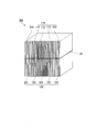
- FIG. 1 shows a viewing angle control body of the present embodiment.
- the viewing angle control body 1 of the present embodiment has a rectangular sheet shape, a louver layer 10 in which a plurality of light transmission bands 11 and a plurality of light shielding bands 12 are alternately provided, and one surface of the louver layer 10.
- the first transparent protective layer 20 provided on the whole and the second transparent protective layer 30 provided on the entire other surface of the louver layer 10.
- the viewing angle control body 1 is provided on the image display surface of the image display body and is preferably used as a peep prevention body.
- the second transparent protective layer 30 is disposed on the light incident side, that is, the image display body side, and the first transparent protective layer 20 is disposed on the light emitting side.
- the longitudinal direction of the rectangular viewing angle control body 1 is the X direction (in FIG. 1, the horizontal direction of the paper surface), and the short side direction of the viewing angle control body 1 (the vertical direction of the paper surface in FIG. 1) is Y.
- the direction and the vertical direction of the surface of the viewing angle control body 1 (that is, the thickness direction of the viewing angle control body 1) are defined as the Z direction.
- the rectangle in this embodiment should just be a rectangle when the schematic shape of an external shape sees the viewing angle control body 1 from a Z direction (in planar view).
- the rectangular right corners may be cut.
- a notch may be formed in any part of the periphery of a rectangle, and the protrusion part which protrudes partially from a rectangle side may be formed.
- the rectangular side may be partially non-linear (for example, curved, zigzag, etc.).
- the light transmittance of the entire viewing angle control body 1 is preferably 45% or more, and more preferably 55% or more.
- the upper limit of the light transmittance is preferably higher, but about 80% is the limit in order to ensure sufficient peeping prevention. Specifically, 45% to 80% is preferable, and 55% to 80% is more preferable.
- the value of light transmittance is D65 as defined in JIS Z 8720 as a light source, and a device that measures the intensity of inspection light emitted from the light source with a light receiving sensor is provided on the optical path of the inspection light.
- the output value of the light receiving sensor when there is no measured object is A
- the output value when the measured object is set on the optical path of the inspection light is B
- the transmitted light transmitted through the measured object is received by the light receiving sensor is B.
- the light transmittance (B / A) ⁇ 100 (unit:%).
- the viewing angle control body 1 of the present embodiment includes a first end region 1 a including one end portion in the longitudinal direction of the viewing angle control body 1 and the other end portion in the longitudinal direction of the viewing angle control body 1. It has the 2nd edge part area
- the average values of the widths of the plurality of light transmission bands 11 are different between the first end region 1a and the second end region 1b and the central region 1c.
- the first end region 1a, the second end region 1b, and the central region 1c are each preferably quadrangular in plan view.
- the width Wc of the central region 1c varies depending on the object to be used of the viewing angle control body 1, but in many objects to be used, the width Wc is 20% or more with respect to the total length in the longitudinal direction of the viewing angle control body 1. % Or less, more preferably 30% or more and 60% or less. If the width W c of the central region 1c is the range, the viewing angle control element 1 of the present embodiment is suitable as a preventive peep, images displayed in the end region of the image display display surface Visibility can be further improved.
- Width W b of width W a and a second end region 1b of the first end region 1a is preferably the longitudinal direction of the length of the viewing angle control element 1 is 10% to 40% or less, 20 % To 35% is more preferable.
- the width W a of the first end region 1a and the width W b of the second end region 1b may be the same or different, but usually are identical.
- the width ratio (%) is obtained from the equation: (100 ⁇ the ratio (%) of the width W c of the central region 1c) / 2.
- the widths W a , W b , and W c of the respective regions are the lengths of the respective regions in the longitudinal direction of the viewing angle control body 1.
- the length in the longitudinal direction of the viewing angle control body 1 is not limited and is, for example, 120 mm or more and 1500 mm or less.
- the effect of the viewing angle control body of the present invention is particularly useful for an image display body having a large display surface.
- the viewing angle control body 1 has a length in the longitudinal direction of, for example, 250 mm or more, and a 300 mm or more is particularly useful.
- the length in the longitudinal direction of the viewing angle control body 1 is preferably 600 mm or less, and more preferably 500 mm or less.
- the length in the longitudinal direction of the viewing angle control body 1 is preferably 250 mm or more and 600 mm or less, and more preferably 300 mm or more and 500 mm or less.
- the length in the short direction of the viewing angle control body 1 is preferably 50 mm or more, more preferably 150 mm or more, and further preferably 175 mm or more.
- the length in the short direction of the viewing angle control body 1 is practically preferably 1000 mm or less, more preferably 500 mm or less, and further preferably 300 mm or less.
- the length of the viewing angle control body 1 in the short direction is preferably 50 mm or greater and 1000 mm or less, more preferably 150 mm or greater and 500 mm or less, and even more preferably 175 mm or greater and 300 mm or less.
- the louver layer 10 includes a plurality of linear light transmission bands 11 and linear light shielding bands 12, and the light transmission bands 11 and the light shielding bands 12 are alternately and repeatedly arranged.
- the light transmission band 11 and the light shielding band 12 are formed along the Y direction.
- FIG. 1 is a schematic view of the viewing angle control body of the present embodiment, in which the number of light transmission bands 11 and light shielding bands 12 is reduced.
- the average value of the widths of the plurality of light transmission bands 11 provided in the first end region 1a is wider than the average value of the widths of the plurality of light transmission bands provided in the center region 1c.
- the average value of the widths of the plurality of light transmission bands 11 provided in the second end region 1b is made wider than the average value of the widths of the plurality of light transmission bands 11 provided in the center region 1c.
- the width of each of the plurality of light transmission bands 11 provided in the first end region 1a is wider than the width of each of the plurality of light transmission bands provided in the center region 1c.
- the width of each of the plurality of light transmission bands 11 provided in the second end region 1b is wider than the width of each of the plurality of light transmission bands 11 provided in the center region 1c.
- the widths of the plurality of light transmission bands 11 provided in the first end region 1a are preferably the same.
- the widths of the plurality of light transmission bands 11 provided in the second end region 1b are preferably the same.
- the widths of the plurality of light transmission bands 11 provided in the central region 1c are preferably the same.
- the widths of the plurality of light transmission bands 11 are the same in each region. If the width of the light transmission band 11 is the same in each region, the viewing angle control body 1 can be easily manufactured.
- all the light shielding bands 12 provided in the first end region 1a, the second end region 1b, and the central region 1c have the same width.
- the width of each light transmission band 11 and the length of each light shielding band 12 are the same.
- the “width” refers to the length in the X direction of the light transmission band 11 or the light shielding band 12 on the light emitting side surface of the louver layer 10.
- the X direction is a direction in which a plurality of light transmission bands 11 and a plurality of light shielding bands 12 are alternately provided.
- the “width of each light transmission band 11 and the length of each light shielding band 12” are the lengths in the Y direction of the light transmission band 11 or the light shielding band 12 on the light emitting side surface of the louver layer 10.
- the above-mentioned “same” of the width of the light transmission band 11 and the width of the light shielding band 12 allows a slight difference, and includes a range within ⁇ 5% of the width design value.
- the viewing angle is controlled by providing the light shielding band 12 in any of the first end region 1a, the second end region 1b, and the central region 1c.
- the central region 1c has a narrower viewing angle than the first end region 1a and the second end region 1b because the light transmission band 11 is narrower than the first end region 1a and the second end region 1b. ing. Accordingly, the central region 1c is a region with higher peep prevention properties.
- the first end region 1a and the second end region 1b have a wide viewing angle because the light transmission band 11 is wider than the central region 1c, but the viewing angle is controlled. It is secured.
- the average value of the widths of the plurality of light transmission bands 11 provided in the central region 1c is preferably 50 ⁇ m or more and 200 ⁇ m or less, and more preferably 100 ⁇ m or more and 150 ⁇ m or less. If the average value of the widths of the plurality of light transmission bands 11 provided in the central region 1c is equal to or greater than the lower limit value, sufficient light transmission can be ensured, and if the average value is less than the upper limit value, peep prevention is more effective. Get higher.
- the average value of the widths of the plurality of light transmission bands 11 provided in the first end region 1a and the second end region 1b is larger than the average value of the widths of the plurality of light transmission bands 11 provided in the central region 1c.
- the width is preferably in the range of 1 ⁇ m to 30 ⁇ m, and more preferably in the range of 5 ⁇ m to 15 ⁇ m.
- Difference between the average value of the widths of the plurality of light transmission bands 11 provided in the first end region 1a and the second end region 1b and the average value of the widths of the plurality of light transmission bands 11 provided in the central region 1c Is higher than the lower limit value, the visibility of the image in the first end region 1a and the second end region 1b is higher, and if it is equal to or lower than the upper limit value, the light transmittance between the adjacent regions is higher. The difference becomes smaller and the difference in visual shading becomes smaller.
- the average value of the widths of the plurality of light transmission bands 11 provided in the first end region 1a is the same as the average value of the widths of the plurality of light transmission bands 11 provided in the second end region 1b. It may be different or different.
- the width of each of the plurality of light transmission bands 11 provided in the central region 1c is preferably 50 ⁇ m or more and 200 ⁇ m or less, and more preferably 100 ⁇ m or more and 150 ⁇ m or less. If the width of each of the plurality of light transmission bands 11 provided in the central region 1c is equal to or greater than the lower limit value, sufficient light transmission can be ensured, and if the width is less than the upper limit value, the peep prevention property is higher. Become.
- the width of each of the plurality of light transmission bands 11 provided in the first end region 1a and the second end region 1b is 1 ⁇ m or more than the width of each of the plurality of light transmission bands 11 provided in the central region 1c.
- It is preferably widened in the range of 30 ⁇ m or less, and more preferably widened in the range of 5 ⁇ m or more and 15 ⁇ m or less.
- the difference between the width of each of the plurality of light transmission bands 11 provided in the first end region 1a and the second end region 1b and the width of each of the plurality of light transmission bands 11 provided in the center region 1c is described above. If it is at least the lower limit value, the visibility of the image in the first end region 1a and the second end region 1b will be higher, and if it is not more than the upper limit value, the difference in light transmittance between the adjacent regions will be increased. It becomes smaller and the difference in visual shading becomes smaller.
- the difference between the average value of the width of the transmission band 11 and the average value of the widths of the plurality of light transmission bands 11 in the central region 1c is preferably a difference in viewing angle of 15 ° or less, more preferably 0.5 ° or more and 10 It is adjusted to be not more than °, more preferably not less than 1 ° and not more than 5 °.
- the light transmittance increases. If the viewing angle difference is large, the difference in light transmittance between adjacent regions increases, and the difference in lightness appears visually. The appearance of the viewing angle control body 1 is impaired. If the difference in viewing angle is equal to or less than the upper limit value, the difference in light transmittance between adjacent regions becomes small, and the difference in visual shading decreases.
- the maximum angle ⁇ 1 of transmitted light in the light transmission band 11 is arctan (average value of widths of the plurality of light transmission bands 11 / light transmission band 11). (Thickness of)).
- the thickness of the light transmission band 11 is the length in the Z direction.
- the average value of the widths of the plurality of light shielding bands 12 is preferably in the range of 1 ⁇ m to 50 ⁇ m, and more preferably in the range of 10 ⁇ m to 30 ⁇ m.
- the width of each of the light shielding bands 12 is preferably in the range of 1 ⁇ m to 50 ⁇ m, and more preferably in the range of 10 ⁇ m to 30 ⁇ m.
- the thickness of the louver layer 10 in this embodiment is constant.
- the “thickness” here is the length of the louver layer 10 in the Z direction.
- the thickness of the louver layer 10 can be obtained by measurement with a cross-sectional photograph of a single body of the viewing angle control body 1 or the louver layer 10, and is an average value of values obtained by measuring 10 or more locations.
- “constant” in the thickness includes a range within the design value ⁇ 5% of the thickness.
- the thickness of the louver layer 10 is preferably 100 ⁇ m or more and 5000 ⁇ m or less, more preferably 120 ⁇ m or more and 1000 ⁇ m or less, and further preferably 150 ⁇ m or more and 500 ⁇ m or less. If the thickness of the louver layer 10 is within the above range, the viewing angle can be easily adjusted and can be easily manufactured.
- “length”, “thickness”, and “width” are values obtained by measuring the length, thickness, or width with respect to an arbitrary 10 locations with a measuring microscope and averaging the measured values. It is.
- the average value of the widths of the plurality of light transmission bands 11 is a value obtained by measuring the widths of the plurality of light transmission bands 11 by the above-described width measurement method and averaging the obtained values.
- the average value of the widths of the plurality of light shielding bands 12 is a value obtained by measuring the widths of the plurality of light shielding bands 12 by the above-described width measurement method and averaging the obtained values.
- the installation angles of the light shielding bands 12 provided in the first end region 1a, the second end region 1b, and the central region 1c are all the same.
- the installation angle is an angle of the light shielding band 12 with respect to the vertical direction of the surface of the viewing angle control body 1 and is an angle in a range of 0 ° or more and less than 90 °.
- “same” of installation angles includes a range of design values ⁇ 2 ° of installation angles.
- the specific installation angle of the light shielding band 12 is preferably 0 ° or more and 3 ° or less, and more preferably 0 ° or more and 1 ° or less.
- the installation angle of the light shielding band 12 provided in the first end region 1a, the second end region 1b, and the central region 1c is equal to or less than the upper limit value, the peep prevention property is further improved.
- the installation angle of the light shielding band 12 is based on the center line of the light shielding band 12 and the vertical direction of the surface in the cross-sectional photograph of the viewing angle control body 1 or the louver layer 10 on the light emitting side of the louver layer 10 as a reference. It can be measured as an angle formed by
- a resin material that transmits the wavelength of the target visible light As a material constituting the light transmission band 11, a resin material that transmits the wavelength of the target visible light is used.
- the wavelength of light transmitted through the light transmission band 11 may be 380 nm or more and 830 nm or less of the entire visible light range, or may be a part thereof.
- a resin material constituting the light transmission band 11 a highly transparent thermoplastic resin or thermosetting resin is used.
- cellulose resin, polyolefin resin, polyester resin, silicone resin, polystyrene resin, polychlorinated resin A vinyl resin, an acrylic resin, a polycarbonate resin, etc. are mentioned.
- a silicone resin is preferable, and a silicone rubber is more preferable in terms of high flexibility, heat resistance, and transparency.
- silicone rubber examples include a silicone rubber composition generally called a millable rubber composed of a diorganopolysiloxane whose molecular chain end is blocked with a hydroxysilyl group or a vinylsilyl group and an organic peroxide; bonded to a silicon atom in the molecule.
- a diorganopolysiloxane having at least two vinyl groups is mixed with an organohydrogenpolysiloxane having at least three hydrogen atoms bonded to silicon atoms (ie, SiH bonds) and a platinum-based catalyst in the molecule.
- examples include a reactive organosilicone rubber composition.
- the light transmission band 11 preferably has a light transmittance of 75% or more when light is incident on only the light transmission band 11 along the Z direction, and more preferably 85% or more. Specifically, it is preferably 75% or more and 100% or less, and more preferably 85% or more and 100% or less.
- a colored resin is used in which a resin material constituting the light transmission band 11 is used as a base material and a colorant such as a pigment or a dye is added thereto.
- the resin material included in the light shielding band 12 the same resin material as that included in the light transmission band 11 can be used.
- the resin material included in the light shielding band 12 may be the same as or different from the resin material included in the light transmission band 11.
- the resin material included in the light-shielding band 12 is preferably the same as the resin material included in the light-transmitting band 11 in that the adhesiveness between the light-transmitting band 11 and the light-shielding band 12 is increased.
- the color tone of the light shielding band 12 is not particularly limited as long as a preferable light shielding property is obtained in the light shielding band 12, and can be, for example, black, red, yellow, green, blue, light blue, or the like.
- the color tone of the light-shielding band 12 can be adjusted by the type and addition amount of the colorant. Since the color tone of the light-shielding band 12 constitutes a color tone recognized when the louver layer 10 is viewed, it is preferable to design in consideration of the design of the viewing angle control body 1.
- the light shielding band 12 preferably has a light transmittance of 40% or less when light is incident on only the light shielding band 12 along the X direction, and more preferably 10% or less. Specifically, 0% to 40% is preferable, and 0% to 10% is more preferable. Such light transmittance has sufficient light blocking properties.
- the colorant contained in the light shielding band 12 include general organic pigments or inorganic pigments such as carbon black, iron oxide, titanium oxide, yellow iron oxide, disazo yellow, and phthalocyanine blue.
- a coloring agent may be used individually by 1 type, and may use 2 or more types together. When a black pigment is not used as the colorant, it is preferable to use a white pigment in combination in order to ensure light shielding properties.
- the first transparent protective layer 20 and the second transparent protective layer 30 are layers made of a transparent resin material, and are provided on the light emitting side surface of the louver layer 10 and function as protective layers for the louver layer 10.
- the first transparent protective layer 20 and the second transparent protective layer 30 preferably have a light transmittance of 75% or more when light is incident along the Z direction, and more preferably 85% or more. Specifically, it is preferably 75% or more and 100% or less, and more preferably 85% or more and 100% or less.
- the transparent resin material constituting the first transparent protective layer 20 and the second transparent protective layer 30 examples include polycarbonate resins, polyester resins, acrylic resins, polyolefin resins (particularly cycloolefin polymers), and cellulose resins. Can be mentioned. Among these transparent resin materials, polycarbonate or polyester resin is preferable because of high transparency and heat resistance. A transparent resin material may be used individually by 1 type, and may use 2 or more types together.
- the thickness of the first transparent protective layer 20 and the second transparent protective layer 30 is preferably 0.01 mm or more and 0.5 mm or less, and more preferably 0.1 mm or more and 0.2 mm or less.
- the louver layer 10 can be sufficiently protected, and if the thickness is not more than the upper limit value, sufficient light transmittance can be ensured.
- the first transparent protective layer 20 and the second transparent protective layer 30 may be the same or different.
- the viewing angle control body 1 of this embodiment can be manufactured by the method which has a louver layer formation process, a 1st transparent protective layer lamination process, and a 2nd transparent protective layer lamination process. Furthermore, the louver layer forming step includes a laminated body forming step, a block body forming step, and a cutting step.
- the laminated body forming step is a step of forming a laminated body by alternately laminating a plurality of light transmission band sheets and a plurality of light shielding band sheets.
- a laminated body having three laminated units is formed. That is, the laminated body formation process in this embodiment has a 1st lamination
- the first laminated unit forming step is a step of forming a first laminated unit by alternately laminating a plurality of first light transmission band sheets and a plurality of first light shielding band sheets.
- the second laminated unit forming step a plurality of second light transmitting band sheets and a plurality of second light shielding band sheets thinner than the first light transmitting band sheet are alternately laminated to form a second laminated unit. It is.
- the third laminated unit forming step a plurality of third light transmitting band sheets and a plurality of third light shielding band sheets that are thicker than the second light transmitting band sheet are alternately laminated to form a third laminated unit. It is.
- the second stacked unit is disposed between the first stacked unit and the third stacked unit. The first stacked unit becomes the first end region 1a, the second stacked unit becomes the central region 1c, and the third stacked unit becomes the second end region 1b.
- the laminate forming step includes the following methods.
- First, the first stacked unit, the second stacked unit, and the third stacked unit are separately prepared in advance. That is, a plurality of first light transmission band sheets and a plurality of first light shielding band sheets are alternately stacked to form a first stacked unit.
- a plurality of second light transmission band sheets and a plurality of second light shielding band sheets are alternately stacked to form a second stacked unit.
- a plurality of third light transmission band sheets and a plurality of third light shielding band sheets are alternately stacked to form a third stacked unit.
- the light transmission band sheet and the light shielding band sheet may be bonded using an adhesive.
- the first stacked unit is stacked on one surface of the second stacked unit, and the third stacked unit is stacked on the other surface of the second stacked unit to form a stacked body.
- An adhesive may be used when stacking the stacked units.
- the following method is mentioned as another specific method of the said laminated body formation process. That is, first, a plurality of first light transmission band sheets and a plurality of first light shielding band sheets are alternately stacked to form a first stacked unit. Next, a plurality of second light transmission band sheets and a plurality of second light shielding band sheets are alternately stacked on one surface of the first lamination unit to form a second lamination unit. Next, a plurality of third light transmission band sheets and a plurality of second light shielding band sheets are alternately stacked on the other surface of the second stack unit to form a third stack unit, Form.
- the average value of the thicknesses of the plurality of second light transmission band sheets is preferably in the range of 50 ⁇ m to less than 200 ⁇ m, and more preferably in the range of 100 ⁇ m to 150 ⁇ m. If the average value of the thicknesses of the plurality of second light transmission band sheets is equal to or higher than the lower limit value, the light transmittance in the central region 1c can be sufficiently secured. Get higher.
- seat is the value which measured the thickness of each of the some sheet
- the thickness of the second light transmission band sheet corresponds to the width of the light transmission band 11 in the central region 1c.
- the average value of the thicknesses of the plurality of first light transmission band sheets and the average value of the thicknesses of the plurality of third light transmission band sheets are based on the average value of the thicknesses of the plurality of second light transmission band sheets. Is preferably in the range of 1 ⁇ m to 30 ⁇ m, more preferably in the range of 5 ⁇ m to 15 ⁇ m.
- the difference between the average value of the thicknesses of the plurality of first light transmission band sheets and the average value of the thicknesses of the plurality of third light transmission band sheets and the average value of the thicknesses of the plurality of second light transmission band sheets If the value is equal to or higher than the lower limit value, the visibility of the image in the first end region 1a and the second end region 1b is further increased.
- the average value of the thicknesses of the plurality of first light transmission band sheets may be the same as or different from the average value of the thicknesses of the plurality of third light transmission band sheets.
- the thickness of the first light transmission band sheet corresponds to the width of the light transmission band 11 in the first end region 1a
- the thickness of the third light transmission band sheet is the light transmission in the second end region 1b. This corresponds to the width of the band 11.
- the thickness of each of the plurality of second light transmission band sheets is preferably in the range of 50 ⁇ m to less than 200 ⁇ m, and more preferably in the range of 100 ⁇ m to 150 ⁇ m. If the thickness of each of the plurality of second light transmission band sheets is equal to or greater than the lower limit value, the light transmittance in the central region 1c can be sufficiently secured, and if the thickness is less than the upper limit value, the peep prevention property is further improved. Get higher.
- the thickness of the second light transmission band sheet corresponds to the width of the light transmission band 11 in the central region 1c.
- the thickness of each of the plurality of first light transmission band sheets and the thickness of each of the plurality of third light transmission band sheets are 1 ⁇ m or more and 30 ⁇ m than the thickness of each of the plurality of second light transmission band sheets.
- the thickness is preferably in the following range, and more preferably in the range of 5 ⁇ m to 15 ⁇ m.
- the difference between the thicknesses of the plurality of first light transmission band sheets and the thicknesses of the plurality of third light transmission band sheets and the thicknesses of the plurality of second light transmission band sheets is equal to or greater than the lower limit value.
- the thickness of the first light transmission band sheet corresponds to the width of the light transmission band 11 in the first end region 1a, and the thickness of the third light transmission band sheet is the light transmission in the second end region 1b. This corresponds to the width of the band 11.
- each of the plurality of first light shielding belt sheets is preferably in the range of 1 ⁇ m to 50 ⁇ m, and more preferably in the range of 10 ⁇ m to 30 ⁇ m.
- the light transmission band sheet can be manufactured by molding a resin material constituting the light transmission band 11 into a sheet shape.
- the light shielding band sheet can be manufactured by molding the resin material constituting the light shielding band 12 into a sheet shape.
- Each of the light transmission band sheet and the light shielding band sheet is formed to have a constant thickness.
- a molding method for molding the resin material into a sheet for example, extrusion molding, calendar molding, press molding, or the like can be applied.
- a block body formation process is a process of pressurizing the layered product to form a block body.
- pressurization of the laminate for example, a roll or a press machine can be used.
- heating is preferably performed in order to increase the adhesion between the sheets.
- the heating temperature is appropriately selected according to the material to be used. When the heating temperature is too high, the uniformity of the thickness of the sheet is impaired, and when the heating temperature is too low, the adhesive force between the sheets may be weakened.
- a cutting process is a process of cut
- the block body 100 is cut so that the thickness of the louver layer 10 is constant.
- a light transmission band sheet 110 first light transmission band sheet 111, second light transmission band sheet 112, third light transmission band sheet 113) and light shielding band sheet 120 are used.
- a cutting blade is cut perpendicularly to the direction in which the first light shielding band sheet 121, the second light shielding band sheet 122, and the third light shielding band sheet 123 are alternately arranged, and the light transmission band sheet 110 and the light shielding layer.
- a method of simultaneously cutting the belt sheet 120 is exemplified. Further, as another cutting method, a cutting blade is cut vertically from one surface of the block body 100 where only the light transmission band sheet 110 or only the light shielding band sheet 120 is exposed, and the cutting blade or the block body is moved so that the light A method of alternately cutting the transmission band sheet 110 and the light shielding band sheet 120 may be used.
- the first transparent protective layer laminating step is a step of laminating the first transparent protective layer on the light emitting side surface of the louver layer obtained by the cutting step.
- a method of laminating the first transparent protective layer for example, there is a method in which the material constituting the first transparent protective layer is previously formed into a sheet shape, and the obtained transparent sheet is adhered to one surface of the louver layer. Can be mentioned.
- an adhesive may be used, or thermocompression bonding may be performed without using the adhesive.
- the adhesive preferably has a high light transmittance after curing.
- those having a light transmittance of preferably 65% or more, more preferably 80% or more in the adhesive layer alone after curing are used. Specifically, it is preferably 65% or more and 100% or less, and more preferably 80% or more and 100% or less.
- adhesives include epoxy adhesives, urethane adhesives, acrylic adhesives, melamine adhesives, polyester adhesives, and silicone adhesives.
- the adhesive may be any one of a thermosetting adhesive, a multi-component reaction adhesive, an ultraviolet curable adhesive, and the like.
- the second transparent protective layer laminating step is a step of laminating the second transparent protective layer on the light incident side surface of the louver layer obtained by the cutting step.
- the method of laminating the second transparent protective layer on the louver layer is the same as the method of laminating the first transparent protective layer on the louver layer.
- the viewing angle control image display body of this embodiment includes an image display body and the viewing angle control body provided on the image display surface of the image display body.
- the size and shape of the viewing angle control body is preferably set to a size and shape corresponding to the display surface of the image display body.
- Examples of the image display body include an image display device that displays a video signal, such as a liquid crystal display device or an organic electroluminescence display device.
- the display surface (screen) of the image display apparatus is a rectangle whose longitudinal direction is the left-right direction with respect to the user. Therefore, the viewing angle control body of the present embodiment that is rectangular is arranged so that its longitudinal direction is along the longitudinal direction of the display surface of the image display device.
- the image display body may be a printed matter printed on paper or a plastic sheet.
- the shape of the printed material is not particularly limited, but the viewing angle control body of the present embodiment is suitable for a rectangular printed material.
- the length of the display surface of the image display body in the longitudinal direction is preferably 600 mm or less, and more preferably 500 mm or less.
- the length in the longitudinal direction of the display surface of the image display body is preferably 250 mm or more and 600 mm or less, and more preferably 300 mm or more and 500 mm or less.
- the length of the display surface of the image display body in the short direction is preferably 50 mm or more, more preferably 150 mm or more, and further preferably 175 mm or more.
- the length of the display surface of the image display body in the short direction is preferably 1000 mm or less, more preferably 500 mm or less, and further preferably 300 mm or less.
- the length of the display surface of the image display body in the short direction is preferably 50 mm to 1000 mm, more preferably 150 mm to 500 mm, and still more preferably 175 mm to 300 mm.
- the viewing angle control body of the present embodiment is particularly suitably used for an information input / output device including an image display device with a touch sensor. This is because information input / output devices often display and input confidential information and are often required to prevent peeping.
- the central region of the viewing angle control body of the present embodiment is controlled so that the viewing angle is narrow, and is a region with particularly high peeping prevention properties. Therefore, it is preferable that the central area of the viewing angle control body is overlaid on the area where the confidential information is displayed.
- the width of the area in which the confidential information is displayed is preferably 20% or more and 80% or less, and more preferably 30% or more and 60% or less with respect to the length in the width direction of the image display body.
- the width of the area where the confidential information is displayed is preferably 10% or more and 100% or less, and more preferably 10% or more and 90% or less with respect to the width of the central area of the viewing angle control body.
- secret information is usually displayed near the center of the display surface of an image display. Therefore, when the viewing angle control body of the present embodiment is provided on the display surface of the image display body, the central area of the viewing angle control body can be easily overlapped with the display of the confidential information, and the confidential information can be viewed. Can be prevented.
- the conventional viewing angle control body is provided on the display surface of the image display body, the image displayed in the end region in the longitudinal direction of the display surface is displayed by the louver layer for the user located in front of the central region.
- the viewing angle may not fall within the viewing angle range. Therefore, it is difficult for the user located in front of the central area to visually recognize the image displayed in the end area of the display surface.
- the average value of the widths of the plurality of light transmission bands in the first end region and the second end region is larger than the average value of the widths of the plurality of light transmission bands in the central region.
- the viewing angle in the first end region and the second end region is wide. Therefore, when a user located in front of the central area views an image displayed in the end area of the display surface, the image falls within the viewing angle range by viewing angle control, and can be easily viewed. Moreover, since the viewing angle is controlled to be narrow in the first end region and the second end region, peep prevention is ensured.
- FIG. 3 shows the viewing angle control body of the present embodiment.
- the viewing angle control body 2 of the present embodiment is the same as that of the first embodiment except that the form of the louver layer is different. That is, the louver layer 40 used in the present embodiment includes the first end region 2a, the second end region 2b, and the central region 2c, and the first louver layer 40 between the first end region 2a and the central region 2c.
- the second intermediate region 2e is provided between the second end region 2b and the central region 2c.
- the average value of the widths of the plurality of light transmission bands 11 provided in the first intermediate region 2d is narrower than the average value of the widths of the plurality of light transmission bands 11 provided in the first end region 2a and the central region 2c. It is made wider than the average value of the widths of the plurality of light transmission bands 11 provided in.
- the average value of the widths of the plurality of light transmission bands 11 provided in the second intermediate region 2e is narrower than the average value of the widths of the plurality of light transmission bands 11 provided in the second end region 2b, and the central region 2c. It is made wider than the average value of the widths of the plurality of light transmission bands 11 provided in.
- the width of each of the plurality of light transmission bands 11 provided in the first end region 2a, the width of each of the plurality of light transmission bands 11 provided in the second end region 2b, and the central region 2c are constant in each region.
- the widths of each of these are constant in each region.
- Each of the plurality of light transmission bands 11 provided in the first end region 2a and the second end region 2b is wider than each of the plurality of light transmission bands 11 provided in the central region 2c. Is the same as the louver layer 10 in the first embodiment.
- the thickness, the material constituting the light transmission band 11, the width of the light shielding band 12, and the material constituting the light shielding band 12 are the same as those in the louver layer 10 in the first embodiment. .
- the width W c of the central region 2c varies depending on the object to be used of the viewing angle control body 2, but in many objects to be used, the width W c is 20% or more with respect to the total length in the longitudinal direction of the viewing angle control body 2. % Or less, more preferably 30% or more and 60% or less. If the width W c of the central region 2c is in the range, the viewing angle control member 2 of the present embodiment is suitable as a preventive peep, images displayed in the end region of the image display display surface Visibility can be further improved.
- Width W e of the width W d and the second intermediate region 2e of the first intermediate region 2d may vary depending on use object of the viewing angle control member 2, in many applications the object, the viewing angle control member 2 It is preferably 5% or more and 20% or less, and more preferably 10% or more and 17.5% or less with respect to the total length in the longitudinal direction. If the width W d and the width W e of the second intermediate region 2e of the first intermediate region 2d is the lower limit or more, it is possible to reduce the difference in light transmittance between the neighboring regions, reduce the difference between the visual shade it can.
- the width W a of the first end region 2 a and the width W b of the second end region 2 b are preferably 5% or more and 20% or less with respect to the total length in the longitudinal direction of the viewing angle control body 2. % To 17.5% is more preferable.
- the width W a of the first end region 2a and the width W b of the second end region 2b may be the same or different, but usually are identical.
- the width W d of the first intermediate region 2d and the width W e of the second intermediate region 2e may be the same or different, but usually are identical.
- ratio of width (%) is (100 - ratio of the width W c of the central region 2c (%) - the percentage of the width W d of the first intermediate region 2d (%) - the width W e of the second intermediate region 2e It is calculated
- the width W a of each region, W b, W c, and W d, W e is that the length of each region in the longitudinal direction of the viewing angle control member 2.
- the average value of the widths of the plurality of light transmission bands 11 provided in the central region 2c is preferably 50 ⁇ m or more and 200 ⁇ m or less, and more preferably 100 ⁇ m or more and 150 ⁇ m or less. If the average value of the widths of the plurality of light transmission bands 11 provided in the central region 2c is equal to or greater than the lower limit value, sufficient light transmission can be ensured, and if the average value is less than the upper limit value, peep prevention is more effective. Get higher.
- the average value of the widths of the plurality of light transmission bands 11 provided in the first intermediate region 2d is wider in the range of 1 ⁇ m or more and 30 ⁇ m or less than the average value of the widths of the plurality of light transmission bands 11 provided in the center region 2c. It is preferable that it is widened in the range of 5 ⁇ m or more and 15 ⁇ m or less.
- the average value of the widths of the plurality of light transmission bands 11 provided in the first end region 2a is 1 ⁇ m or more and 30 ⁇ m or less than the average value of the widths of the plurality of light transmission bands 11 provided in the first intermediate region 2d.
- the difference between the average value of the widths of the plurality of light transmission bands 11 provided in the first end region 2a and the average value of the widths of the plurality of light transmission bands 11 provided in the first intermediate region 2d is equal to or greater than the lower limit value. If so, the visibility of the image in the first end region 2a is higher, and if it is equal to or less than the upper limit value, the difference in light transmittance between adjacent regions becomes smaller, and the difference in visual shading is reduced. Get smaller.
- the average value of the widths of the plurality of light transmission bands 11 provided in the second intermediate region 2e is wider in the range of 1 ⁇ m to 30 ⁇ m than the average value of the widths of the plurality of light transmission bands 11 provided in the center region 2c. It is preferable that it is widened in the range of 5 ⁇ m or more and 15 ⁇ m or less.
- the average value of the widths of the plurality of light transmission bands 11 provided in the second end region 2b is 1 ⁇ m or more and 30 ⁇ m or less than the average value of the widths of the plurality of light transmission bands 11 provided in the second intermediate region 2e.
- the difference between the average value of the widths of the plurality of light transmission bands 11 provided in the second end region 2b and the average value of the widths of the plurality of light transmission bands 11 provided in the second intermediate region 2e is equal to or greater than the lower limit value. If so, the visibility of the image in the second end region 2b is higher, and if it is equal to or less than the upper limit value, the difference in light transmittance between adjacent regions becomes smaller, and the difference in visual shading is reduced. Get smaller.
- the width of each of the light transmission bands 11 provided in the central region 2c is preferably 50 ⁇ m or more and 200 ⁇ m or less, and more preferably 100 ⁇ m or more and 150 ⁇ m or less. If the width of each of the plurality of light transmission bands 11 provided in the central region 2c is equal to or greater than the lower limit value, sufficient light transmittance can be secured, and if the width is less than the upper limit value, the peep prevention property is higher. Become.
- the width of each of the plurality of light transmission bands 11 provided in the first intermediate region 2d is made wider in the range of 1 ⁇ m to 30 ⁇ m than the width of each of the plurality of light transmission bands 11 provided in the center region 2c.
- each of the plurality of light transmission bands 11 provided in the first intermediate region 2d and the width of each of the plurality of light transmission bands 11 provided in the center region 2c is equal to or greater than the lower limit value, If the visibility of the image in the intermediate region 2d is higher and is equal to or less than the upper limit value, the difference in light transmittance between adjacent regions becomes smaller, and the difference in visual shading becomes smaller.
- the width of each of the plurality of light transmission bands 11 provided in the first end region 2a is within a range of 1 ⁇ m or more and 30 ⁇ m or less than the width of each of the plurality of light transmission bands 11 provided in the first intermediate region 2d.
- the difference between the width of each of the plurality of light transmission bands 11 provided in the first end region 2a and the width of each of the plurality of light transmission bands 11 provided in the first intermediate region 2d is greater than or equal to the lower limit value. For example, the visibility of the image in the first end region 2a is higher, and if it is equal to or less than the upper limit value, the difference in light transmittance between adjacent regions is reduced, and the difference in visual shading is reduced. .
- the width of each of the plurality of light transmission bands 11 provided in the second intermediate region 2e is wider than the width of each of the plurality of light transmission bands 11 provided in the center region 2c in a range of 1 ⁇ m to 30 ⁇ m. It is preferable that it is widened in the range of 5 ⁇ m to 15 ⁇ m. If the difference between the width of each of the plurality of light transmission bands 11 provided in the second intermediate region 2e and the width of each of the plurality of light transmission bands 11 provided in the center region 2c is equal to or greater than the lower limit value, If the visibility of the image in the second intermediate region 2e is higher and is equal to or less than the upper limit value, the difference in light transmittance between adjacent regions becomes smaller, and the difference in visual shading becomes smaller.
- the width of each of the plurality of light transmission bands 11 provided in the second end region 2b is within a range of 1 ⁇ m or more and 30 ⁇ m or less than the width of each of the plurality of light transmission bands 11 provided in the second intermediate region 2e. It is preferably widened, and more preferably widened in the range of 5 ⁇ m to 15 ⁇ m.
- the difference between the width of each of the plurality of light transmission bands 11 provided in the second end region 2b and the width of each of the plurality of light transmission bands 11 provided in the second intermediate region 2e is greater than or equal to the lower limit value. For example, the visibility of the image in the second end region 2b becomes higher, and if it is equal to or less than the upper limit value, the difference in light transmittance between adjacent regions becomes smaller and the difference in visual shading becomes smaller. .
- the difference in viewing angle is adjusted so that the difference in viewing angle is preferably 15 ° or less, more preferably 0.5 ° or more and 10 ° or less, and further preferably 1 ° or more and 5 ° or less.
- the difference in viewing angle increases. If the viewing angle difference is large, the difference in light transmittance between adjacent regions increases, and the difference in lightness appears visually. The appearance of the viewing angle control body 2 is impaired. If the difference in viewing angle is equal to or less than the upper limit value, the difference in light transmittance between adjacent regions becomes small, and the difference in visual shading decreases.
- the installation angles of the light shielding bands 12 provided in the first end region 2a, the second end region 2b, the central region 2c, the first intermediate region 2d, and the second intermediate region 2e are all the same.
- the “same” installation angle here includes a range of the design value ⁇ 2 ° of the installation angle.
- the specific installation angle of the light shielding band 12 is preferably 0 ° or more and 3 ° or less, and more preferably 0 ° or more and 1 ° or less. If the installation angle of the light shielding band 12 provided in the first end region 2a, the second end region 2b, the central region 2c, the first intermediate region 2d, and the second intermediate region 2e is equal to or less than the upper limit value, More preventive.
- the manufacturing method which manufactures the viewing angle control body 2 of this embodiment is demonstrated.
- the manufacturing method of the viewing angle control body 2 of this embodiment is the same as that of 1st Embodiment except a laminated body formation process and a cutting process differing.
- the laminated body forming step is a step of alternately laminating a plurality of light transmitting band sheets and a plurality of light shielding band sheets to form a laminated body, and forms a laminated body having five laminated units. That is, the laminated body forming process in the present embodiment includes a first laminated unit forming process, a second laminated unit forming process, a third laminated unit forming process, a fourth laminated unit forming process, and a fifth laminated unit forming process.
- the first laminated unit forming step is a step of forming a first laminated unit by alternately laminating a plurality of first light transmission band sheets and a plurality of first light shielding band sheets.
- the second laminated unit forming step a plurality of second light transmitting band sheets and a plurality of second light shielding band sheets thinner than the first light transmitting band sheet are alternately laminated to form a second laminated unit. It is.
- the third laminated unit forming step a plurality of third light transmitting band sheets and a plurality of third light shielding band sheets that are thicker than the second light transmitting band sheet are alternately laminated to form a third laminated unit.
- a plurality of fourth light transmission band sheets and a plurality of fourth light shielding band sheets are alternately laminated which are thinner than the first light transmission band sheet and thicker than the second light transmission band sheet. And forming a fourth laminated unit.
- the fifth laminated unit forming step a plurality of fifth light transmission band sheets and a plurality of fifth light shielding band sheets that are thinner than the third light transmission band sheet and thicker than the second light transmission band sheet are alternately laminated. And forming a fifth laminated unit.
- the fourth laminated unit is arranged between the first laminated unit and the second laminated unit, and the fifth laminated unit is arranged between the second laminated unit and the third laminated unit. Then, the second stacked unit is disposed between the fourth stacked unit and the fifth stacked unit.
- the first stacked unit is the first end region 2a
- the second stacked unit is the central region 2c
- the third stacked unit is the second end region 2b
- the fourth stacked unit is the first end region 2c. It becomes the intermediate region 2d
- the fifth stacked unit becomes the second intermediate region 2e.
- a first laminated unit, a second laminated unit, a third laminated unit, a fourth laminated unit, and a fifth laminated unit are separately prepared in advance. That is, a plurality of first light transmission band sheets and a plurality of light shielding band sheets are alternately stacked to form a first stacked unit. A plurality of second light transmission band sheets and a plurality of second light shielding band sheets are alternately stacked to form a second stacked unit. A plurality of third light transmission band sheets and a plurality of third light shielding band sheets are alternately stacked to form a third stacked unit.
- a plurality of fourth light transmission band sheets and a plurality of fourth light shielding band sheets are alternately stacked to form a fourth stacked unit.
- a plurality of fifth light transmission band sheets and a plurality of fifth light shielding band sheets are alternately stacked to form a fifth stacked unit.
- the light transmission band sheet and the light shielding band sheet may be bonded using an adhesive.
- the fourth stacked unit is stacked on one surface of the second stacked unit.
- the fifth stacked unit is stacked on the other surface of the second stacked unit.
- the first laminated unit is laminated on the surface of the fourth laminated unit opposite to the second laminated unit.
- a third laminate unit is laminated on the surface of the fifth laminate unit opposite to the second laminate unit to form a laminate.
- An adhesive may be used when stacking the stacked units.
- the following method is mentioned as another specific method of the said laminated body formation process. That is, first, a plurality of first light transmission band sheets and a plurality of first light shielding band sheets are alternately stacked to form a first stacked unit. Next, a plurality of fourth light transmission band sheets and a plurality of fourth light shielding band sheets are alternately stacked on one surface of the first lamination unit to form a fourth lamination unit. Next, a plurality of second light transmission band sheets and a plurality of second light shielding band sheets are alternately stacked on the surface of the fourth lamination unit opposite to the first lamination unit, and the second lamination unit is formed. Form.
- a plurality of fifth light transmission band sheets and a plurality of fifth light shielding band sheets are alternately stacked on the surface of the second lamination unit opposite to the fourth lamination unit, and the fifth lamination unit is formed.
- a plurality of third light transmission band sheets and a plurality of third light shielding band sheets are alternately laminated on the surface of the fourth lamination unit opposite to the second lamination unit, and the third lamination unit is formed. To form a laminate.
- the average value of the thicknesses of the plurality of second light transmission band sheets is preferably in the range of 50 ⁇ m to less than 200 ⁇ m, and more preferably in the range of 100 ⁇ m to 150 ⁇ m. If the average value of the thicknesses of the plurality of second light transmission band sheets is equal to or higher than the lower limit value, the light transmittance in the central region 2c can be sufficiently secured. Get higher.
- the thickness of the second light transmission band sheet corresponds to the width of the light transmission band 11 in the central region 2c.
- the average value of the thicknesses of the plurality of fourth light transmission band sheets is preferably thicker in the range of 1 ⁇ m to 30 ⁇ m than the average value of the thicknesses of the plurality of second light transmission band sheets. It is more preferable that the thickness is in the range of. If the difference between the average value of the thicknesses of the plurality of fourth light transmission band sheets and the average value of the thicknesses of the plurality of second light transmission band sheets is equal to or greater than the lower limit value, the image in the first intermediate region 2d is displayed. If the visibility is further reduced to the upper limit value or less, the difference in light transmittance between adjacent areas becomes small, and the difference in visual shading decreases.
- the thickness of the fourth light transmission band sheet corresponds to the width of the light transmission band 11 in the first intermediate region 2d.
- the average thickness of the plurality of first light transmission band sheets is preferably thicker in the range of 1 ⁇ m to 30 ⁇ m than the average thickness of the plurality of fourth light transmission band sheets, and is preferably 5 ⁇ m to 15 ⁇ m. It is more preferable that the thickness is in the range of.
- the first end region 2a If the difference between the average value of the thicknesses of the plurality of first light transmission band sheets and the average value of the thicknesses of the plurality of fourth light transmission band sheets is equal to or greater than the lower limit value, the first end region 2a If the visibility of the image is further increased and the value is not more than the upper limit value, the difference in light transmittance between adjacent regions becomes small, and the difference in visual shading decreases.
- the thickness of the first light transmission band sheet corresponds to the width of the light transmission band 11 in the first end region 2a.
- the average thickness of the plurality of fifth light transmission band sheets is preferably thicker in the range of 1 ⁇ m to 30 ⁇ m than the average thickness of the plurality of second light transmission band sheets, and is 5 ⁇ m to 15 ⁇ m.
- the thickness is in the range of. If the difference between the average value of the thicknesses of the plurality of fifth light transmission band sheets and the average value of the thicknesses of the plurality of second light transmission band sheets is greater than or equal to the lower limit value, the image in the second intermediate region 2e If the visibility is further reduced to the upper limit value or less, the difference in light transmittance between adjacent areas becomes small, and the difference in visual shading decreases.
- the thickness of the fifth light transmission band sheet corresponds to the width of the light transmission band 11 in the second intermediate region 2e.
- the average thickness of the plurality of third light transmission band sheets is preferably thicker in the range of 1 ⁇ m to 30 ⁇ m than the average thickness of the plurality of fifth light transmission band sheets, and is 5 ⁇ m to 15 ⁇ m. It is more preferable that the thickness is in the range of. If the difference between the average value of the thicknesses of the plurality of third light transmission band sheets and the average value of the thicknesses of the plurality of fifth light transmission band sheets is equal to or greater than the lower limit value, the second end region 2b If the visibility of the image is further increased and the value is not more than the upper limit value, the difference in light transmittance between adjacent regions becomes small, and the difference in visual shading decreases.
- the thickness of the third light transmission band sheet corresponds to the width of the light transmission band 11 in the second end region 2b.
- the average value of the thicknesses of the plurality of first light transmission band sheets and the average value of the thicknesses of the plurality of third light transmission band sheets may be the same or different, or may be the plurality of fourth light transmissions.
- the average value of the thickness of the band sheet and the average value of the thicknesses of the plurality of fifth light transmission band sheets may be the same or different.
- the thickness of each of the plurality of second light transmission band sheets is preferably in the range of 50 ⁇ m to less than 200 ⁇ m, and more preferably in the range of 100 ⁇ m to 150 ⁇ m. If the thickness of each of the plurality of second light transmission band sheets is equal to or greater than the lower limit value, the light transmittance in the central region 2c can be sufficiently secured, and if the thickness is less than the upper limit value, the peep prevention property is further improved. Get higher.
- the thickness of the second light transmission band sheet corresponds to the width of the light transmission band 11 in the central region 2c.
- Each of the plurality of fourth light transmission band sheets is preferably thicker in the range of 1 ⁇ m to 30 ⁇ m than the thickness of each of the plurality of second light transmission band sheets, and in the range of 5 ⁇ m to 15 ⁇ m. More preferably, it is thick. If the difference between the thickness of each of the plurality of fourth light transmission band sheets and the thickness of each of the plurality of second light transmission band sheets is equal to or greater than the lower limit value, the visibility of the image in the first intermediate region 2d is improved. If it is higher and is less than or equal to the upper limit value, the difference in light transmittance between adjacent regions becomes smaller, and the difference in visual shading becomes smaller.
- the thickness of the fourth light transmission band sheet corresponds to the width of the light transmission band 11 in the first intermediate region 2d.
- Each of the plurality of first light transmission band sheets is preferably thicker in the range of 1 ⁇ m to 30 ⁇ m than the thickness of each of the plurality of fourth light transmission band sheets, and in the range of 5 ⁇ m to 15 ⁇ m. More preferably, it is thick. If the difference between the thickness of each of the plurality of first light transmission band sheets and the thickness of each of the plurality of fourth light transmission band sheets is equal to or greater than the lower limit value, the visibility of the image in the first end region 2a is increased.
- the thickness of the first light transmission band sheet corresponds to the width of the light transmission band 11 in the first end region 2a.
- Each of the plurality of fifth light transmission band sheets is preferably thicker in the range of 1 ⁇ m to 30 ⁇ m than the thickness of each of the plurality of second light transmission band sheets, and in the range of 5 ⁇ m to 15 ⁇ m. More preferably, it is thick.
- the difference between the thicknesses of the plurality of fifth light transmission band sheets and the thicknesses of the plurality of second light transmission band sheets is equal to or greater than the lower limit value, the visibility of the image in the second intermediate region 2e is improved. If it is higher and is less than or equal to the upper limit value, the difference in light transmittance between adjacent regions becomes smaller, and the difference in visual shading becomes smaller.
- the thickness of the fifth light transmission band sheet corresponds to the width of the light transmission band 11 in the second intermediate region 2e.
- Each of the plurality of third light transmission band sheets is preferably thicker in the range of 1 ⁇ m to 30 ⁇ m than the thickness of each of the plurality of fifth light transmission band sheets, and in the range of 5 ⁇ m to 15 ⁇ m.
- the thickness of each of the plurality of third light transmission band sheets and the thickness of each of the plurality of fifth light transmission band sheets is equal to or greater than the lower limit value, the visibility of the image in the second end region 2b is increased. If the value becomes higher and is not more than the above upper limit value, the difference in light transmittance between adjacent regions becomes smaller, and the difference in visual shading becomes smaller.
- the thickness of the third light transmission band sheet corresponds to the width of the light transmission band 11 in the second end region 2b.
- the block body 100 is cut so that the thickness of the louver layer 40 is constant.
- a light transmission band sheet 110 first light transmission band sheet 111, second light transmission band sheet 112, third light transmission band sheet 113, fourth light transmission band) Sheet 114, fifth light transmission band sheet 115
- light shielding band sheet 120 first light shielding band sheet 121, second light shielding band sheet 122, third light shielding band sheet 123, and fourth light shielding band sheet 124.
- a method of cutting the light transmission band sheet 110 and the light shielding band sheet 120 at the same time by cutting a cutting blade perpendicular to the direction in which the fifth light shielding band sheets 125) are alternately arranged by cutting a cutting blade perpendicular to the direction in which the fifth light shielding band sheets 125) are alternately arranged.
- a cutting blade is cut vertically from one surface of the block body 100 where only the light transmission band sheet 110 or only the light shielding band sheet 120 is exposed, and the cutting blade or the block body is moved so that the light
- the louver layer 40 having five regions having different widths of the light transmission band 11 can be formed by the above cutting step.
- the usage form of the viewing angle control body of this embodiment is the same as that of the first embodiment. Therefore, by providing the viewing angle control body of the present embodiment on the display surface of the image display body, it is possible to ensure peep prevention. Also in this embodiment, the average value of the widths of the plurality of light transmission bands in the first end region and the second end region is wider than the average value of the widths of the plurality of light transmission bands in the central region. The viewing angles in the first end region and the second end region are wide. Therefore, when a user located in front of the central area views an image displayed in the end area of the display surface, the image falls within the viewing angle range of viewing angle control, and thus can be easily viewed.
- the viewing angle control body since the viewing angle control body has an intermediate region, the width of the light transmission band can be finely adjusted as compared to the viewing angle control body of the first embodiment, and the field of view between adjacent regions can be adjusted. The difference in corners can be reduced.
- the display surface of an image display device tends to increase in size, and when a viewing angle control body is provided on the display surface, the visibility of an image displayed on the end region of the display surface tends to be low.
- the viewing angle control body of the present embodiment that can finely adjust the viewing angle and easily reduce the difference in viewing angle between adjacent regions is used, it can be used even for an image display device with a large display surface. Both the prevention and the visibility of the end region can be easily achieved.
- FIG. 5 shows the viewing angle control body of this embodiment.
- the viewing angle control body 3 of this embodiment is the same as that of the first embodiment except that the form of the louver layer is different.
- the louver layer 50 in the present embodiment also has a first end region 3a, a second end region 3b, and a central region 3c.
- the width of the light transmission band 11 is gradually increased from the center in the longitudinal direction (X direction) of the viewing angle control body 3 toward the end. Therefore, the width of the light transmission band 11 is not the same in each of the first end region 3a, the second end region 3b, and the central region 3c, but gradually changes.
- the width W c of the central region 3c is preferably 20% or more and 80% or less with respect to the total length in the longitudinal direction of the viewing angle control body 3, and 30 % To 60% is more preferable.
- the width W a of the first end region 3 a and the width W b of the second end region 3 b are preferably 5% or more and 20% or less with respect to the total length in the longitudinal direction of the viewing angle control body 3. % To 17.5% is more preferable.
- the width of the light transmission band 11 is gradually changed and it is not easy to visually divide the region, for example, in the region near the center, the longitudinal direction of the viewing angle control body 3
- the region of 80% of the length is the central region 3c, and among the remaining regions, the region of 10% of the length in the longitudinal direction of the viewing angle control body 3 is the first end region 3a.
- the width of the region may be determined as appropriate, for example, a region of 10% of the length in the longitudinal direction is set as the second end region 3b.
- the average value of the widths of the plurality of light transmission bands 11 provided in the central region 3c is preferably 50 ⁇ m or more and 200 ⁇ m or less, and is 100 ⁇ m or more and 150 ⁇ m or less. It is more preferable.
- the average value of the widths of the plurality of light transmission bands 11 provided in the first end region 3a and the second end region 3b is larger than the average value of the widths of the plurality of light transmission bands 11 provided in the center region 3c.
- the width is preferably in the range of 1 ⁇ m to 30 ⁇ m, and more preferably in the range of 5 ⁇ m to 15 ⁇ m.
- the width of each of the plurality of light transmission bands 11 provided in the central region 3c is preferably 50 ⁇ m or more and 200 ⁇ m or less, and more preferably 100 ⁇ m or more and 150 ⁇ m or less.
- the width of each of the light transmission bands 11 provided in the first end region 3a and the second end region 3b is within a range of 1 ⁇ m or more and 30 ⁇ m or less than the width of each of the light transmission bands 11 provided in the central region 3c. It is preferably widened, and more preferably widened in the range of 5 ⁇ m to 15 ⁇ m.
- the difference between the average value of the widths of the plurality of light transmission bands 11 in the first end region 3a and the average value of the widths of the plurality of light transmission bands 11 in the center region 3c, and the second end portion is preferably a difference in viewing angle of 15 ° or less, more preferably It is adjusted to be 0.5 ° to 10 °, more preferably 1 ° to 5 °.
- the thickness, the material constituting the light transmission band 11, the installation angle of the light shielding band 12, the width of the light shielding band 12, and the material constituting the light shielding band 12 are the same as in the first embodiment. Similar to the louver layer 10.
- the manufacturing method which manufactures the viewing angle control body 3 of this embodiment is demonstrated.
- the manufacturing method of the viewing angle control body 3 of this embodiment is the same as that of 1st Embodiment except a laminated body formation process differing.
- a laminated body is formed using the several light transmission band sheet
- a plurality of light transmitting band sheets and a plurality of light shielding band sheets are alternately laminated to form a laminated body, and the target thickness of the laminated body
- the thickness of the light transmission band sheet to be laminated on the light shielding band sheet is gradually reduced until the thickness becomes half of the thickness, and then the light transmission to be laminated on the light shielding band sheet until the target thickness of the laminate is reached.
- the thickness of the band sheet is gradually increased.
- the manufacturing method of the viewing angle control body 3 of the present embodiment includes the step (a) of laminating the light shielding band sheet a on the light transmission band sheet a, and the light on the light shielding band sheet a.
- step (a) laminating a light-shielding band sheet a 1 on the light transmission band sheet a 1, a thin light transmission band than the light transmission band sheet a 1 on the light-shielding band sheet a 1 laminating the use sheet a 2, and laminating a light-shielding band sheet a 2 on the optical transmission band sheet a 2, including.
- step (c) a light transmission band sheet c 1 thinner than the light transmission band sheet a 2 is laminated on the light shielding band sheet a 2 , and light shielding is performed on the light transmission band sheet c 1.
- the usage form of the viewing angle control body of this embodiment is the same as that of the first embodiment. Therefore, by providing the viewing angle control body of the present embodiment on the image display body display surface, it is possible to ensure peep prevention. Also in the present embodiment, the average value of the plurality of light transmission bands in the first end region and the second end region is wider than the average value of the plurality of light transmission bands in the central region, The viewing angles in the first end region and the second end region are wide. Therefore, when a user located in front of the central area views an image displayed in the end area of the display surface, the image falls within the viewing angle range of the viewing angle control, and thus can be easily viewed.
- the viewing angle control body of the present embodiment has a light transmission band whose width gradually increases from the center in the longitudinal direction toward the end, so that the viewing angle gradually increases from the center in the longitudinal direction toward the end. It has become. Therefore, it is easier to achieve both the peep prevention and the visibility of the image displayed in the end region. Further, the difference in shading between adjacent regions can be reduced, and the appearance of the viewing angle control body is improved.
- the present invention is not limited to the above embodiment.
- the light transmission band and the light shielding band may not be formed along the Y direction, and may be formed obliquely with respect to the Y direction.
- the inclination angle is, for example, 1 ° or more and 20 ° or less with respect to the Y direction.
- the viewing angle control body is provided on the surface of the liquid crystal display device, the use of a light transmission band and a light shielding band formed obliquely with respect to the Y direction can easily suppress the occurrence of interference fringes.
- the shape of each region is a trapezoid or a parallelogram.
- the short direction Y
- the viewing angle control body may be provided on the screen so that the light transmission band and the light shielding band are arranged obliquely with respect to (direction).
- the inclination angle in that case is also set to, for example, 1 ° or more and 20 ° or less with respect to the Y direction.
- the installation angles of the light shielding bands in each region may not be the same.
- the installation angle of the light shielding band in the first end region may be different from the installation angle of the light shielding band in the central region, or the installation angle of the light shielding band in the second end region and the installation angle of the light shielding band in the central region.
- the installation angle of the light shielding band in the first intermediate area may be different from the installation angle of the light shielding band in the central area, or the installation angle of the light shielding band in the second intermediate area is different from the installation angle of the light shielding band in the central area. Also good.
- the installation angle of the light shielding band in the first intermediate region may be different from the installation angle of the light shielding band in the first end region, or the installation angle of the light shielding band in the second intermediate region and the light shielding band in the second end region.
- the installation angle may be different.
- the installation angle of the light shielding band is the same throughout the viewing angle control body.
- the width of the light transmission band is the same in each region.
- a region where the width of the light transmission band gradually changes and a region where the width of the light transmission band is the same may be mixed.
- the width of the light transmission band may gradually increase as the distance from the central region increases.
- the width of the light transmission band may gradually increase as the distance from the central region increases.
- the width of the light transmission band may gradually increase as the distance from the central region increases.
- the width of the light transmission band may be the same in the first end region and the second end region of the third embodiment.
- the first intermediate region and the second intermediate region of the third embodiment may be further divided into a plurality of regions, and the width of the light transmission band may be different in each of the divided regions.
- the width of the light transmission band provided in the region far from the center region is made larger than the width of the light transmission band provided in the region near the center region.
- the width of the light transmission band in each divided area may be the same or may gradually change.
- the viewing angle control body does not have to be a rectangle, and may be, for example, a square or another shape (such as a rhombus, a polygon other than a rectangle, a perfect circle, an ellipse, or the like).
- the viewing angle control body of the present invention is preferably rectangular as in the above embodiment.
- the first end region is a region including one end of the viewing angle control body in any one direction A along the surface direction of the viewing angle control body
- the partial region is a region including the other end of the viewing angle control body in the direction A.
- the central region is a region between the first end region and the second end region.
- the direction A is appropriately determined depending on the shape of the viewing angle control body, the shape of the image display body, or the like.
- the direction A can be a direction perpendicular to the light shading band and the longitudinal direction of the light shielding band.
- an adhesive layer may be provided on at least one of the surface of the transparent protective layer on the light emitting side and the surface of the transparent protective layer on the light incident side.
- This adhesive layer is a layer composed of a highly transparent pressure-sensitive adhesive or adhesive, and is a layer for fixing the viewing angle control body to an adherend such as an image display body or a touch panel.
- the adhesive layer preferably has a light transmittance of 75% or more when light is incident along the Z direction, and more preferably 85% or more. Specifically, it is preferably 75% or more and 100% or less, and more preferably 85% or more and 100% or less.
- an adhesive layer is comprised with an adhesive
- an acrylic adhesive, a urethane type adhesive, a rubber-type adhesive etc. can be used, for example.
- an elastomer can be used as an adhesive.
- Specific examples of the elastomer include silicone rubber, silicone gel, urethane rubber, urethane gel, and the like. Among these, silicone rubber is preferable in that there is little adhesive residue and high transparency.
- the adhesive may be re-peelable.
- the removable adhesive a commercially available one can be used without limitation as long as it is transparent.
- an adhesive layer is comprised with an adhesive agent
- an acrylic adhesive a urethane type adhesive agent, etc.
- an acrylic adhesive is preferable because of its high adhesive strength.
- the pressure-sensitive adhesive and the adhesive may be used alone or in combination of two or more.
- a method of laminating the adhesive layer for example, a method of laminating the adhesive layer on the transparent protective layer after applying the adhesive on the surface of the release sheet to form the adhesive layer. Can be mentioned.
- the adhesive layer forming adhesive is directly applied to the transparent protective layer to form the adhesive layer, and if necessary, a release sheet is applied to the adhesive layer. The method of laminating is mentioned.
- the viewing angle control body of the present invention does not include at least one of the first transparent protective layer and the second transparent protective layer, and may include an adhesive layer instead. That is, the viewing angle control body in which the first transparent protective layer is provided on the light emitting side surface of the louver layer and the adhesive layer is provided on the light incident side surface, and the light emitting side surface of the louver layer is attached to the light emitting side surface.
- a viewing angle control body may be provided in which a deposition layer is provided and a second transparent protective layer is provided on the light incident side surface. Moreover, in this invention, it does not need to have at least one of a 1st transparent protective layer and a sticking layer.
- the viewing angle control body of the present invention When the viewing angle control body of the present invention is used for an information input / output device including an image display device with a touch sensor, the viewing angle control body is usually disposed between the image display device and the touch panel.
- the viewing angle control body When manufacturing the information input / output device, the viewing angle control body may be attached to the image display body and then the touch panel may be attached to the viewing angle control body, or the viewing angle control body may be attached to the touch panel and then viewed.
- An image display body may be attached to the body. At the time of attachment, an adhesive layer provided on the viewing angle control body may or may not be used.
- a region that is 80% of the length in the longitudinal direction of the rectangular viewing angle control body is the central region, and among the remaining regions, the longitudinal direction of the viewing angle control body is
- the area width is determined for convenience, the area of 10% of the length is the first end area and the area of 10% of the length in the longitudinal direction of the viewing angle control body is the second end area.
- the average width of the light transmission band provided in the first end region and the second end region is wider than the average width of the light transmission band provided in the center region.
- the average width of the light transmission band can be obtained by measuring the widths of all the light transmission bands in each region and averaging those values in a cross-sectional photograph of a single body of the viewing angle control body or louver layer. .
- Example 1 A viewing angle control body having the configuration shown in FIG. 1 was manufactured. First, a first light transmission band sheet and a third light transmission band sheet having a thickness of 190 ⁇ m made of transparent silicone rubber (manufactured by Shin-Etsu Chemical Co., Ltd., trade name: KE153U) were prepared. Also, a second light transmission band sheet having a thickness of 150 ⁇ m made of transparent silicone rubber (trade name: KE153U, manufactured by Shin-Etsu Chemical Co., Ltd.) was prepared.
- a sheet for a light-shielding band having a thickness of 20 ⁇ m made of a material obtained by adding 15 parts by mass of carbon black to 100 parts by mass of transparent silicone rubber (manufactured by Shin-Etsu Chemical Co., Ltd .; trade name: KE153U) was prepared. This was used as a first light shielding sheet, a second light shielding sheet, and a third light shielding sheet.
- a plurality of first light transmission band sheets and a plurality of first light shielding band sheets were alternately stacked to form a first stacked unit.
- a plurality of second light transmission band sheets and a plurality of second light shielding band sheets were alternately stacked to form a second stacked unit.
- a plurality of third light transmission band sheets and a plurality of third light shielding band sheets were alternately stacked to form a third stacked unit.
- the three laminated units were bonded to form a laminated body so that the second laminated unit was disposed between the first laminated unit and the third laminated unit.
- the laminated body was pressurized while heating to obtain a block body in which three laminated units were integrated.
- the block body was sliced perpendicularly to the surface of each sheet to obtain a louver layer 10.
- a polycarbonate sheet (first transparent protective layer 20) coated with a thermosetting adhesive (manufactured by Shin-Etsu Chemical Co., Ltd., trade name: KE1825) is bonded to the surface of the obtained louver layer 10 on the light emitting side.
- the adhesive was heat cured.
- a polycarbonate sheet (second transparent protective layer 30) coated with a thermosetting adhesive (manufactured by Shin-Etsu Chemical Co., Ltd., trade name: KE1825) is bonded to the surface of the obtained louver layer 10 on the light incident side.
- the adhesive was heat cured.
- a viewing angle control body having a rectangular shape in plan view, a length in the longitudinal direction of 340 mm, and a length in the lateral direction of 200 mm was obtained.
- the obtained viewing angle control body was placed on a sheet of paper on which an image was printed on the entire surface, and visually observed and evaluated for peeping prevention and visibility of the image on the display surface edge region. At that time, the distance between the eyes and the paper surface was 300 mm.
- the viewing angle control body of this example has a peep prevention property not only in the central region but also in the end region, and moreover, the image of the display surface end region can be sufficiently visually recognized.
- Example 1 A viewing angle control body was obtained in the same manner as in Example 1 except that the thickness of the first light transmission band sheet and the thickness of the third light transmission band sheet were both 150 mm. Similarly to Example 1, the viewing angle control body of this example was evaluated by visually observing the peeping prevention property and the visibility of the image on the display surface edge region. Although the viewing angle control body of this example had a peep prevention property in the center region and the end region, the image of the display surface end region could not be visually recognized.
- the viewing angle control body of the present invention is displayed in the end region of the display surface of the image display body while having an anti-peep property that makes it difficult for the image to be viewed even if the image displayed by the image display body is viewed.
- the visibility of the displayed image can be secured.
- a viewing angle control body having the above-described effects can be easily manufactured.
- the viewing angle control image display body of the present invention has a peep prevention property and ensures the visibility of the image displayed in the end region of the image display body display surface.
- Second intermediate regions 10 1, 2, 3 Viewing angle control bodies 1a, 2a, 3a First end regions 1b, 2b, 3b Second end regions 1c, 2c, 3c Central region 2d First intermediate region 2e Second intermediate regions 10, 40, 50 louver layer 11 light transmission band 12 light shielding band 20 first transparent protective layer 30 second transparent protective layer 100 block body 110 light transmission band sheet 111 first light transmission band sheet 112 second light transmission band sheet 113 third Light transmission band sheet 114 Fourth light transmission band sheet 115 Fifth light transmission band sheet 120 Light shielding band sheet 121 First light shielding band sheet 122 Second light shielding band sheet 123 Third light shielding band sheet 124 Fourth Light shielding band sheet 125 Fifth light shielding sheet
Landscapes
- Physics & Mathematics (AREA)
- General Physics & Mathematics (AREA)
- Engineering & Computer Science (AREA)
- Theoretical Computer Science (AREA)
- Business, Economics & Management (AREA)
- Accounting & Taxation (AREA)
- Marketing (AREA)
- Optics & Photonics (AREA)
- Optical Elements Other Than Lenses (AREA)
- Liquid Crystal (AREA)
- Devices For Indicating Variable Information By Combining Individual Elements (AREA)
Abstract
本発明の視野角制御体(1)は、複数の光透過帯(11)と複数の遮光帯(12)とが交互に設けられているルーバー層(10)を備え、前記複数の光透過帯(11)と前記複数の遮光帯(12)とが交互に設けられている方向Aにおける視野角制御体(1)の一方の端部を含む第1端部領域(1a)と、前記方向Aにおける視野角制御体(1)の他方の端部を含む第2端部領域(1b)と、第1端部領域(1a)及び第2端部領域(1b)の間の中央領域(1c)とを有し、第1端部領域(1a)及び第2端部領域(1b)に設けられた複数の光透過帯(11)の幅の平均値が、前記中央領域(1c)に設けられた複数の光透過帯(11)の幅の平均値よりも広い。
Description
本発明は、画像表示装置等によって表示される画像の視野角を制御する視野角制御体及びその製造方法、並びに、視野角制御体を備えた視野角制御画像表示体に関する。
本願は、2017年6月5日に、日本に出願された特願2017-110879号に基づき優先権を主張し、その内容をここに援用する。
本願は、2017年6月5日に、日本に出願された特願2017-110879号に基づき優先権を主張し、その内容をここに援用する。
情報を表示すると共に入力するための装置として、タッチパネル付きの画像表示装置を備えた情報入出力機器が広く普及している。この情報入出力機器においては、画像表示装置に表示される画像に秘匿情報が含まれることがあるため、画像表示装置の表示面には、手前側からの視認性を損なうことなく、左右側及び向かい側からの覗き見を防止するためのシート状の視野角制御体が設けられている。
覗き見防止用の視野角制御体としては、光透過帯と遮光帯とが交互に設けられたルーバー層と、ルーバー層の一方の面に設けられた透明保護層と、前記ルーバー層の他方の面に設けられた透明性の粘着層とが積層された積層体が知られている(特許文献1)。また、視野角を制御するルーバー層において、光透過帯の幅を漸次変化させて、視野角制御体全体の視野角を制限するものが知られている(特許文献2,3)。
覗き見防止用の視野角制御体としては、光透過帯と遮光帯とが交互に設けられたルーバー層と、ルーバー層の一方の面に設けられた透明保護層と、前記ルーバー層の他方の面に設けられた透明性の粘着層とが積層された積層体が知られている(特許文献1)。また、視野角を制御するルーバー層において、光透過帯の幅を漸次変化させて、視野角制御体全体の視野角を制限するものが知られている(特許文献2,3)。
しかし、画像表示装置の表示面に、特許文献1~3に記載されているような視野角制御体を設けると、表示面端部領域にて表示された画像の視認性が低下することがある。特に、近年では画像表示装置の表示面が大型化される傾向にあり、大型の表示面の場合には端部領域に表示された画像の視認性低下が顕著である。
本発明は、画像表示装置等の画像表示体により表示された画像を覗き見されても画像が視認されにくい覗き見防止性を有しながらも、画像表示体表示面の端部領域に表示された画像の視認性を確保できる視野角制御体及びその製造方法を提供することを目的とする。
また、本発明は、覗き見防止性を有すると共に、画像表示体表示面の端部領域に表示された画像の視認性が確保されている視野角制御画像表示体を提供することを目的とする。
また、本発明は、覗き見防止性を有すると共に、画像表示体表示面の端部領域に表示された画像の視認性が確保されている視野角制御画像表示体を提供することを目的とする。
本発明は、以下の態様を包含する。
[1]光透過帯と遮光帯とが交互に複数設けられているルーバー層を備えるシート状の視野角制御体であって、
該視野角制御体の面方向に沿った方向Aにおける視野角制御体の一方の端部を含む第1端部領域と、前記方向Aにおける視野角制御体の他方の端部を含む第2端部領域と、前記第1端部領域及び前記第2端部領域の間に形成された中央領域とを有し、
前記第1端部領域及び前記第2端部領域に設けられた光透過帯の、前記方向Aに沿う幅が、前記中央領域に設けられた光透過帯の、前記方向Aに沿う幅よりも広い、視野角制御体。
[2]前記視野角制御体が長方形であり、前記方向Aが視野角制御体の長手方向である、[1]に記載の視野角制御体。
[3]前記中央領域に設けられた光透過帯の幅が50μm以上200μm以下であり、前記第1端部領域及び前記第2端部領域に設けられた光透過帯の幅が前記中央領域に設けられた光透過帯の幅よりも1μm以上30μm以下の範囲で広くなっている、[1]又は[2]に記載の視野角制御体。
[4]前記第1端部領域と前記中央領域との間に第1中間領域を有すると共に、前記第2端部領域と前記中央領域との間に第2中間領域を有し、前記第1中間領域に設けられた光透過帯の幅は、前記第1端部領域に設けられた光透過帯の幅よりも狭く且つ前記中央領域に設けられた光透過帯の幅よりも広く、前記第2中間領域に設けられた光透過帯の幅は、前記第2端部領域に設けられた光透過帯の幅よりも狭く且つ前記中央領域に設けられた光透過帯の幅よりも広い、[1]又は[2]に記載の視野角制御体。
[5]前記中央領域に設けられた光透過帯の幅が50μm以上200μm以下であり、前記第1中間領域に設けられた光透過帯の幅が前記中央領域に設けられた光透過帯の幅よりも1μm以上30μm以下の範囲で広くされ、前記第1端部領域に設けられた光透過帯の幅が前記第1中間領域に設けられた光透過帯の幅よりも1μm以上30μm以下の範囲で広くされ、前記第2中間領域に設けられた光透過帯の幅が前記中央領域に設けられた光透過帯の幅よりも1μm以上30μm以下の範囲で広くされ、前記第2端部領域に設けられた光透過帯の幅が前記第2中間領域に設けられた光透過帯の幅よりも1μm以上30μm以下の範囲で広くされている、[4]に記載の視野角制御体。
[6]互いに隣接する領域の視野角の差が15°以下になるように各領域の光透過帯の幅が調整されている、[1]~[5]のいずれか一に記載の視野角制御体。
[7]各領域内での光透過帯の幅が同一とされている、[1]~[6]のいずれか一に記載の視野角制御体。
[1]光透過帯と遮光帯とが交互に複数設けられているルーバー層を備えるシート状の視野角制御体であって、
該視野角制御体の面方向に沿った方向Aにおける視野角制御体の一方の端部を含む第1端部領域と、前記方向Aにおける視野角制御体の他方の端部を含む第2端部領域と、前記第1端部領域及び前記第2端部領域の間に形成された中央領域とを有し、
前記第1端部領域及び前記第2端部領域に設けられた光透過帯の、前記方向Aに沿う幅が、前記中央領域に設けられた光透過帯の、前記方向Aに沿う幅よりも広い、視野角制御体。
[2]前記視野角制御体が長方形であり、前記方向Aが視野角制御体の長手方向である、[1]に記載の視野角制御体。
[3]前記中央領域に設けられた光透過帯の幅が50μm以上200μm以下であり、前記第1端部領域及び前記第2端部領域に設けられた光透過帯の幅が前記中央領域に設けられた光透過帯の幅よりも1μm以上30μm以下の範囲で広くなっている、[1]又は[2]に記載の視野角制御体。
[4]前記第1端部領域と前記中央領域との間に第1中間領域を有すると共に、前記第2端部領域と前記中央領域との間に第2中間領域を有し、前記第1中間領域に設けられた光透過帯の幅は、前記第1端部領域に設けられた光透過帯の幅よりも狭く且つ前記中央領域に設けられた光透過帯の幅よりも広く、前記第2中間領域に設けられた光透過帯の幅は、前記第2端部領域に設けられた光透過帯の幅よりも狭く且つ前記中央領域に設けられた光透過帯の幅よりも広い、[1]又は[2]に記載の視野角制御体。
[5]前記中央領域に設けられた光透過帯の幅が50μm以上200μm以下であり、前記第1中間領域に設けられた光透過帯の幅が前記中央領域に設けられた光透過帯の幅よりも1μm以上30μm以下の範囲で広くされ、前記第1端部領域に設けられた光透過帯の幅が前記第1中間領域に設けられた光透過帯の幅よりも1μm以上30μm以下の範囲で広くされ、前記第2中間領域に設けられた光透過帯の幅が前記中央領域に設けられた光透過帯の幅よりも1μm以上30μm以下の範囲で広くされ、前記第2端部領域に設けられた光透過帯の幅が前記第2中間領域に設けられた光透過帯の幅よりも1μm以上30μm以下の範囲で広くされている、[4]に記載の視野角制御体。
[6]互いに隣接する領域の視野角の差が15°以下になるように各領域の光透過帯の幅が調整されている、[1]~[5]のいずれか一に記載の視野角制御体。
[7]各領域内での光透過帯の幅が同一とされている、[1]~[6]のいずれか一に記載の視野角制御体。
[8]光透過帯用シートと遮光帯用シートとを交互に複数積層して積層体を形成する積層体形成工程と、前記積層体を加圧してブロック体を形成するブロック体形成工程と、前記ブロック体を前記各シート表面に対して垂直に切断する切断工程とを有し、
前記積層体形成工程は、第1光透過帯用シートと遮光帯用シートとを交互に複数積層して第1積層ユニットを形成する第1積層ユニット形成工程と、第1光透過帯用シートより薄い第2光透過帯用シートと遮光帯用シートとを交互に複数積層して第2積層ユニットを形成する第2積層ユニット形成工程と、第2光透過帯用シートより厚い第3光透過帯用シートと遮光帯用シートとを交互に複数積層して第3積層ユニットを形成する第3積層ユニット形成工程とを有し、第1積層ユニットと第3積層ユニットとの間に第2積層ユニットを配置する、視野角制御体の製造方法。
[9]前記第2光透過帯用シートの厚さを50μm以上200μm以下とし、前記第1光透過帯用シートの厚さ及び前記第3光透過帯用シートの厚さを前記第2光透過帯用シートの厚さよりも1μm以上30μm以下の範囲で厚くする、[8]に記載の視野角制御体の製造方法。
[10]前記積層体形成工程は、第1光透過帯用シートより薄く且つ第2光透過帯用シートより厚い第4光透過帯用シートと遮光帯用シートとを交互に複数積層して第4積層ユニットを形成する第4積層ユニット形成工程と、第3光透過帯用シートより薄く且つ第2光透過帯用シートより厚い第5光透過帯用シートと遮光帯用シートとを積層して第5積層ユニットを形成する第5積層ユニット形成工程とをさらに有し、第1積層ユニットと第2積層ユニットとの間に第4積層ユニットを配置し、第2積層ユニットと第3積層ユニットとの間に第5積層ユニットを配置し、第4積層ユニットと第5積層ユニットとの間に第2積層ユニットを配置する、[8]に記載の視野角制御体の製造方法。
[11]前記第2光透過帯用シートの厚さを50μm以上200μm以下とし、前記第4光透過帯用シートの厚さを前記第2光透過帯用シートの厚さよりも1μm以上30μm以下の範囲で厚くし、前記第1光透過帯用シートの厚さを前記第4光透過帯用シートの厚さよりも1μm以上30μm以下の範囲で厚くし、前記第5光透過帯用シートの厚さを前記第2光透過帯用シートの厚さよりも1μm以上30μm以下の範囲で厚くし、前記第2光透過帯用シートの厚さを前記第5光透過帯用シートの厚さよりも1μm以上30μm以下の範囲で厚くする、[10]に記載の視野角制御体の製造方法。
前記積層体形成工程は、第1光透過帯用シートと遮光帯用シートとを交互に複数積層して第1積層ユニットを形成する第1積層ユニット形成工程と、第1光透過帯用シートより薄い第2光透過帯用シートと遮光帯用シートとを交互に複数積層して第2積層ユニットを形成する第2積層ユニット形成工程と、第2光透過帯用シートより厚い第3光透過帯用シートと遮光帯用シートとを交互に複数積層して第3積層ユニットを形成する第3積層ユニット形成工程とを有し、第1積層ユニットと第3積層ユニットとの間に第2積層ユニットを配置する、視野角制御体の製造方法。
[9]前記第2光透過帯用シートの厚さを50μm以上200μm以下とし、前記第1光透過帯用シートの厚さ及び前記第3光透過帯用シートの厚さを前記第2光透過帯用シートの厚さよりも1μm以上30μm以下の範囲で厚くする、[8]に記載の視野角制御体の製造方法。
[10]前記積層体形成工程は、第1光透過帯用シートより薄く且つ第2光透過帯用シートより厚い第4光透過帯用シートと遮光帯用シートとを交互に複数積層して第4積層ユニットを形成する第4積層ユニット形成工程と、第3光透過帯用シートより薄く且つ第2光透過帯用シートより厚い第5光透過帯用シートと遮光帯用シートとを積層して第5積層ユニットを形成する第5積層ユニット形成工程とをさらに有し、第1積層ユニットと第2積層ユニットとの間に第4積層ユニットを配置し、第2積層ユニットと第3積層ユニットとの間に第5積層ユニットを配置し、第4積層ユニットと第5積層ユニットとの間に第2積層ユニットを配置する、[8]に記載の視野角制御体の製造方法。
[11]前記第2光透過帯用シートの厚さを50μm以上200μm以下とし、前記第4光透過帯用シートの厚さを前記第2光透過帯用シートの厚さよりも1μm以上30μm以下の範囲で厚くし、前記第1光透過帯用シートの厚さを前記第4光透過帯用シートの厚さよりも1μm以上30μm以下の範囲で厚くし、前記第5光透過帯用シートの厚さを前記第2光透過帯用シートの厚さよりも1μm以上30μm以下の範囲で厚くし、前記第2光透過帯用シートの厚さを前記第5光透過帯用シートの厚さよりも1μm以上30μm以下の範囲で厚くする、[10]に記載の視野角制御体の製造方法。
[12]画像表示体と、前記画像表示体の画像表示側に設けられた[1]~[7]のいずれか一に記載の視野角制御体とを備える、視野角制御画像表示体。
[13]前記画像表示体に秘匿情報が表示され、前記秘匿情報の表示に前記視野角制御体の中央領域が重ねられている、[12]に記載の視野角制御画像表示体。
[13]前記画像表示体に秘匿情報が表示され、前記秘匿情報の表示に前記視野角制御体の中央領域が重ねられている、[12]に記載の視野角制御画像表示体。
また、本発明は、以下の態様を包含する。
[1] 複数の光透過帯と複数の遮光帯とが交互に設けられているルーバー層を備える視野角制御体であって、
前記複数の光透過帯と前記複数の遮光帯とが交互に設けられている方向Aにおける視野角制御体の一方の端部を含む第1端部領域と、前記方向Aにおける視野角制御体の他方の端部を含む第2端部領域と、前記第1端部領域及び前記第2端部領域の間の中央領域とを有し、
前記第1端部領域及び前記第2端部領域に設けられた前記複数の光透過帯の幅の平均値が、前記中央領域に設けられた前記複数の光透過帯の幅の平均値よりも広い、視野角制御体。
[2] 前記視野角制御体が平面視で長方形であり、前記方向Aが視野角制御体の長手方向である、[1]に記載の視野角制御体。
[3] 前記中央領域に設けられた前記複数の光透過帯の幅の平均値が50μm以上200μm以下であり、前記第1端部領域及び前記第2端部領域に設けられた前記複数の光透過帯の幅の平均値が前記中央領域に設けられた前記複数の光透過帯の幅の平均値よりも1μm以上30μm以下の範囲で広い、[1]又は[2]に記載の視野角制御体。
[4] 前記第1端部領域と前記中央領域との間に第1中間領域、及び前記第2端部領域と前記中央領域との間に第2中間領域を有し、前記第1中間領域に設けられた前記複数の光透過帯の幅の平均値は、前記第1端部領域に設けられた前記複数の光透過帯の幅の平均値よりも狭く且つ前記中央領域に設けられた前記複数の光透過帯の幅の平均値よりも広く、前記第2中間領域に設けられた前記複数の光透過帯の幅の平均値は、前記第2端部領域に設けられた前記複数の光透過帯の幅の平均値よりも狭く且つ前記中央領域に設けられた前記複数の光透過帯の幅の平均値よりも広い、[1]又は[2]に記載の視野角制御体。
[5] 前記中央領域に設けられた前記複数の光透過帯の幅の平均値が50μm以上200μm以下であり、前記第1中間領域に設けられた前記複数の光透過帯の幅の平均値が前記中央領域に設けられた前記複数の光透過帯の幅の平均値よりも1μm以上30μm以下の範囲で広く、前記第1端部領域に設けられた前記複数の光透過帯の幅の平均値が前記第1中間領域に設けられた前記複数の光透過帯の幅の平均値よりも1μm以上30μm以下の範囲で広く、前記第2中間領域に設けられた前記複数の光透過帯の幅の平均値が前記中央領域に設けられた前記複数の光透過帯の幅の平均値よりも1μm以上30μm以下の範囲で広く、前記第2端部領域に設けられた前記複数の光透過帯の幅の平均値が前記第2中間領域に設けられた前記複数の光透過帯の幅の平均値よりも1μm以上30μm以下の範囲で広い、[4]に記載の視野角制御体。
[6] 前記第1端部領域の視野角と、前記中央領域の視野角との差が15°以下であり、
前記中央領域の視野角と、前記第2端部領域の視野角との差が15°以下である、請求項1~5のいずれか一項に記載の視野角制御体。
[7] 前記第1端部領域内での前記複数の光透過帯の幅がそれぞれ同一であり、
前記第2端部領域内での前記複数の光透過帯の幅がそれぞれ同一であり、
前記中央領域内での前記複数の光透過帯の幅がそれぞれ同一である、[1]~[6]のいずれか一項に記載の視野角制御体。
[8] 前記中央領域の幅が、視野角制御体の長手方向の全長に対して、20%以上80%以下であることが好ましく、30%以上60%以下であることがより好ましい、[1]~[7]のいずれか一項に記載の視野角制御体。
[9] 前記第1端部領域の幅及び前記第2端部領域の幅が、視野角制御体の長手方向の全長に対して、10%以上40%以下であることが好ましく、20%以上35%以下であることがより好ましい、[1]~[8]のいずれか一項に記載の視野角制御体。
[10] 前記複数の遮光帯の幅の平均値が、1μm以上50μm以であることが好ましく、10μm以上30μm以下であることがより好ましい、[1]~[9]のいずれか一項に記載の視野角制御体。
[11] 複数の光透過帯用シートと複数の遮光帯用シートとを交互に積層して積層体を形成することと、前記積層体を加圧してブロック体を形成することと、前記ブロック体を前記複数の光透過帯用シートと前記複数の遮光帯用シートとを交互に積層した方向に沿って切断することとを有し、
前記積層体を形成することは、複数の第1光透過帯用シートと複数の第1遮光帯用シートとを交互に積層して第1積層ユニットを形成することと、前記第1光透過帯用シートより薄い複数の第2光透過帯用シートと複数の第2遮光帯用シートとを交互に積層して第2積層ユニットを形成することと、前記第2光透過帯用シートより厚い複数の第3光透過帯用シートと複数の第3遮光帯用シートとを交互に積層して第3積層ユニットを形成すること、及び前記第1積層ユニットと前記第3積層ユニットとの間に前記第2積層ユニットを配置することを含む、視野角制御体の製造方法。
[12] 前記複数の第2光透過帯用シートの厚さの平均値が50μm以上200μm以下であり、前記複数の第1光透過帯用シートの厚さの平均値及び前記複数の第3光透過帯用シートの厚さの平均値が前記複数の第2光透過帯用シートの厚さの平均値よりも1μm以上30μm以下の範囲で厚い、[11]に記載の視野角制御体の製造方法。
[13] 前記積層体を形成することは、さらに、前記第1光透過帯用シートより薄く且つ前記第2光透過帯用シートより厚い複数の第4光透過帯用シートと複数の第4遮光帯用シートとを交互に積層して第4積層ユニットを形成すること、前記第3光透過帯用シートより薄く且つ前記第2光透過帯用シートより厚い複数の第5光透過帯用シートと複数の第5遮光帯用シートとを交互に積層して第5積層ユニットを形成すること、前記第1積層ユニットと前記第2積層ユニットとの間に前記第4積層ユニットを配置すること、前記第2積層ユニットと前記第3積層ユニットとの間に前記第5積層ユニットを配置すること、及び前記第4積層ユニットと前記第5積層ユニットとの間に前記第2積層ユニットを配置することを含む、[11]に記載の視野角制御体の製造方法。
[14] 前記複数の第2光透過帯用シートの厚さの平均値が50μm以上200μm以下であり、前記複数の第4光透過帯用シートの厚さの平均値が前記複数の第2光透過帯用シートの厚さの平均値よりも1μm以上30μm以下の範囲で厚く、前記複数の第1光透過帯用シートの厚さの平均値が前記複数の第4光透過帯用シートの厚さの平均値よりも1μm以上30μm以下の範囲で厚く、前記複数の第5光透過帯用シートの厚さの平均値が前記複数の第2光透過帯用シートの厚さの平均値よりも1μm以上30μm以下の範囲で厚く、前記複数の第2光透過帯用シートの厚さの平均値が前記複数の第5光透過帯用シートの厚さの平均値よりも1μm以上30μm以下の範囲で厚い、[13]に記載の視野角制御体の製造方法。
[15] 画像表示体と、前記画像表示体の画像表示側に設けられた[1]~[10]のいずれか一項に記載の視野角制御体とを備える、視野角制御画像表示体。
[16] 前記画像表示体に秘匿情報が表示され、前記秘匿情報が表示される領域に前記視野角制御体の中央領域が重ねられている、[15]に記載の視野角制御画像表示体。
[1] 複数の光透過帯と複数の遮光帯とが交互に設けられているルーバー層を備える視野角制御体であって、
前記複数の光透過帯と前記複数の遮光帯とが交互に設けられている方向Aにおける視野角制御体の一方の端部を含む第1端部領域と、前記方向Aにおける視野角制御体の他方の端部を含む第2端部領域と、前記第1端部領域及び前記第2端部領域の間の中央領域とを有し、
前記第1端部領域及び前記第2端部領域に設けられた前記複数の光透過帯の幅の平均値が、前記中央領域に設けられた前記複数の光透過帯の幅の平均値よりも広い、視野角制御体。
[2] 前記視野角制御体が平面視で長方形であり、前記方向Aが視野角制御体の長手方向である、[1]に記載の視野角制御体。
[3] 前記中央領域に設けられた前記複数の光透過帯の幅の平均値が50μm以上200μm以下であり、前記第1端部領域及び前記第2端部領域に設けられた前記複数の光透過帯の幅の平均値が前記中央領域に設けられた前記複数の光透過帯の幅の平均値よりも1μm以上30μm以下の範囲で広い、[1]又は[2]に記載の視野角制御体。
[4] 前記第1端部領域と前記中央領域との間に第1中間領域、及び前記第2端部領域と前記中央領域との間に第2中間領域を有し、前記第1中間領域に設けられた前記複数の光透過帯の幅の平均値は、前記第1端部領域に設けられた前記複数の光透過帯の幅の平均値よりも狭く且つ前記中央領域に設けられた前記複数の光透過帯の幅の平均値よりも広く、前記第2中間領域に設けられた前記複数の光透過帯の幅の平均値は、前記第2端部領域に設けられた前記複数の光透過帯の幅の平均値よりも狭く且つ前記中央領域に設けられた前記複数の光透過帯の幅の平均値よりも広い、[1]又は[2]に記載の視野角制御体。
[5] 前記中央領域に設けられた前記複数の光透過帯の幅の平均値が50μm以上200μm以下であり、前記第1中間領域に設けられた前記複数の光透過帯の幅の平均値が前記中央領域に設けられた前記複数の光透過帯の幅の平均値よりも1μm以上30μm以下の範囲で広く、前記第1端部領域に設けられた前記複数の光透過帯の幅の平均値が前記第1中間領域に設けられた前記複数の光透過帯の幅の平均値よりも1μm以上30μm以下の範囲で広く、前記第2中間領域に設けられた前記複数の光透過帯の幅の平均値が前記中央領域に設けられた前記複数の光透過帯の幅の平均値よりも1μm以上30μm以下の範囲で広く、前記第2端部領域に設けられた前記複数の光透過帯の幅の平均値が前記第2中間領域に設けられた前記複数の光透過帯の幅の平均値よりも1μm以上30μm以下の範囲で広い、[4]に記載の視野角制御体。
[6] 前記第1端部領域の視野角と、前記中央領域の視野角との差が15°以下であり、
前記中央領域の視野角と、前記第2端部領域の視野角との差が15°以下である、請求項1~5のいずれか一項に記載の視野角制御体。
[7] 前記第1端部領域内での前記複数の光透過帯の幅がそれぞれ同一であり、
前記第2端部領域内での前記複数の光透過帯の幅がそれぞれ同一であり、
前記中央領域内での前記複数の光透過帯の幅がそれぞれ同一である、[1]~[6]のいずれか一項に記載の視野角制御体。
[8] 前記中央領域の幅が、視野角制御体の長手方向の全長に対して、20%以上80%以下であることが好ましく、30%以上60%以下であることがより好ましい、[1]~[7]のいずれか一項に記載の視野角制御体。
[9] 前記第1端部領域の幅及び前記第2端部領域の幅が、視野角制御体の長手方向の全長に対して、10%以上40%以下であることが好ましく、20%以上35%以下であることがより好ましい、[1]~[8]のいずれか一項に記載の視野角制御体。
[10] 前記複数の遮光帯の幅の平均値が、1μm以上50μm以であることが好ましく、10μm以上30μm以下であることがより好ましい、[1]~[9]のいずれか一項に記載の視野角制御体。
[11] 複数の光透過帯用シートと複数の遮光帯用シートとを交互に積層して積層体を形成することと、前記積層体を加圧してブロック体を形成することと、前記ブロック体を前記複数の光透過帯用シートと前記複数の遮光帯用シートとを交互に積層した方向に沿って切断することとを有し、
前記積層体を形成することは、複数の第1光透過帯用シートと複数の第1遮光帯用シートとを交互に積層して第1積層ユニットを形成することと、前記第1光透過帯用シートより薄い複数の第2光透過帯用シートと複数の第2遮光帯用シートとを交互に積層して第2積層ユニットを形成することと、前記第2光透過帯用シートより厚い複数の第3光透過帯用シートと複数の第3遮光帯用シートとを交互に積層して第3積層ユニットを形成すること、及び前記第1積層ユニットと前記第3積層ユニットとの間に前記第2積層ユニットを配置することを含む、視野角制御体の製造方法。
[12] 前記複数の第2光透過帯用シートの厚さの平均値が50μm以上200μm以下であり、前記複数の第1光透過帯用シートの厚さの平均値及び前記複数の第3光透過帯用シートの厚さの平均値が前記複数の第2光透過帯用シートの厚さの平均値よりも1μm以上30μm以下の範囲で厚い、[11]に記載の視野角制御体の製造方法。
[13] 前記積層体を形成することは、さらに、前記第1光透過帯用シートより薄く且つ前記第2光透過帯用シートより厚い複数の第4光透過帯用シートと複数の第4遮光帯用シートとを交互に積層して第4積層ユニットを形成すること、前記第3光透過帯用シートより薄く且つ前記第2光透過帯用シートより厚い複数の第5光透過帯用シートと複数の第5遮光帯用シートとを交互に積層して第5積層ユニットを形成すること、前記第1積層ユニットと前記第2積層ユニットとの間に前記第4積層ユニットを配置すること、前記第2積層ユニットと前記第3積層ユニットとの間に前記第5積層ユニットを配置すること、及び前記第4積層ユニットと前記第5積層ユニットとの間に前記第2積層ユニットを配置することを含む、[11]に記載の視野角制御体の製造方法。
[14] 前記複数の第2光透過帯用シートの厚さの平均値が50μm以上200μm以下であり、前記複数の第4光透過帯用シートの厚さの平均値が前記複数の第2光透過帯用シートの厚さの平均値よりも1μm以上30μm以下の範囲で厚く、前記複数の第1光透過帯用シートの厚さの平均値が前記複数の第4光透過帯用シートの厚さの平均値よりも1μm以上30μm以下の範囲で厚く、前記複数の第5光透過帯用シートの厚さの平均値が前記複数の第2光透過帯用シートの厚さの平均値よりも1μm以上30μm以下の範囲で厚く、前記複数の第2光透過帯用シートの厚さの平均値が前記複数の第5光透過帯用シートの厚さの平均値よりも1μm以上30μm以下の範囲で厚い、[13]に記載の視野角制御体の製造方法。
[15] 画像表示体と、前記画像表示体の画像表示側に設けられた[1]~[10]のいずれか一項に記載の視野角制御体とを備える、視野角制御画像表示体。
[16] 前記画像表示体に秘匿情報が表示され、前記秘匿情報が表示される領域に前記視野角制御体の中央領域が重ねられている、[15]に記載の視野角制御画像表示体。
本態様の視野角制御体においては、視野角制御体全体にわたって遮光帯の設置角が同一とされていることが好ましい。ここで、設置角とは、視野角制御体表面の垂直方向に対する遮光帯の角度であって、0°以上90°未満の範囲の角度である。
本態様の視野角制御体においては、ルーバー層の厚さが一定とされていることが好ましい。
本態様の視野角制御体においては、遮光帯の幅が、視野角制御体1の全体にわたって同一であることが好ましい。
本態様の視野角制御体の製造方法においては、ルーバー層の厚さが一定になるようにブロック体を切断することが好ましい。
本態様の視野角制御体においては、ルーバー層の厚さが一定とされていることが好ましい。
本態様の視野角制御体においては、遮光帯の幅が、視野角制御体1の全体にわたって同一であることが好ましい。
本態様の視野角制御体の製造方法においては、ルーバー層の厚さが一定になるようにブロック体を切断することが好ましい。
本発明の視野角制御体は、画像表示体により表示された画像を覗き見されても画像が視認されにくい覗き見防止性を有しながらも、画像表示体表示面の端部領域に表示された画像の視認性を確保できる。
本発明の視野角制御体の製造方法によれば、上記の効果を有する視野角制御体を容易に製造できる。
本発明の視野角制御画像表示体は、覗き見防止性を有する共に、画像表示体表示面の端部領域に表示された画像の視認性が確保されている。
本発明の視野角制御体の製造方法によれば、上記の効果を有する視野角制御体を容易に製造できる。
本発明の視野角制御画像表示体は、覗き見防止性を有する共に、画像表示体表示面の端部領域に表示された画像の視認性が確保されている。
<第1実施形態>
本発明の第1実施形態の視野角制御体について説明する。
図1に、本実施形態の視野角制御体を示す。本実施形態の視野角制御体1は、長方形のシート状であり、複数の光透過帯11と複数の遮光帯12とが交互に設けられているルーバー層10と、ルーバー層10の一方の面の全体に設けられた第1透明保護層20と、ルーバー層10の他方の面の全面に設けられた第2透明保護層30とを備える。前記視野角制御体1は、画像表示体の画像表示面に設けられ、覗き見防止体として好適に使用される。
視野角制御体1においては、第2透明保護層30が光入射側、すなわち画像表示体側に配置され、第1透明保護層20が光出射側に配置される。
本実施形態では、長方形の視野角制御体1の長手方向をX方向(図1においては紙面の左右方向)、視野角制御体1の短手方向(図1においては紙面の垂直方向)をY方向、視野角制御体1の表面の垂直方向(すなわち視野角制御体1の厚さ方向)をZ方向とする。
なお、本実施形態における長方形は、外形の概略形状が、Z方向から視野角制御体1を見たときに(平面視で)、長方形になっていればよい。例えば、長方形の直角の角の少なくとも1つが隅切り加工されてもよい。また、長方形の周縁のいずれかの部分に切り欠きが形成されてもよいし、長方形の辺から部分的に突出する突出部が形成されてもよい。また、長方形の辺が部分的に非直線状(例えば、曲線状、ジグザグ状等)になっていてもよい。
本発明の第1実施形態の視野角制御体について説明する。
図1に、本実施形態の視野角制御体を示す。本実施形態の視野角制御体1は、長方形のシート状であり、複数の光透過帯11と複数の遮光帯12とが交互に設けられているルーバー層10と、ルーバー層10の一方の面の全体に設けられた第1透明保護層20と、ルーバー層10の他方の面の全面に設けられた第2透明保護層30とを備える。前記視野角制御体1は、画像表示体の画像表示面に設けられ、覗き見防止体として好適に使用される。
視野角制御体1においては、第2透明保護層30が光入射側、すなわち画像表示体側に配置され、第1透明保護層20が光出射側に配置される。
本実施形態では、長方形の視野角制御体1の長手方向をX方向(図1においては紙面の左右方向)、視野角制御体1の短手方向(図1においては紙面の垂直方向)をY方向、視野角制御体1の表面の垂直方向(すなわち視野角制御体1の厚さ方向)をZ方向とする。
なお、本実施形態における長方形は、外形の概略形状が、Z方向から視野角制御体1を見たときに(平面視で)、長方形になっていればよい。例えば、長方形の直角の角の少なくとも1つが隅切り加工されてもよい。また、長方形の周縁のいずれかの部分に切り欠きが形成されてもよいし、長方形の辺から部分的に突出する突出部が形成されてもよい。また、長方形の辺が部分的に非直線状(例えば、曲線状、ジグザグ状等)になっていてもよい。
視野角制御体1の全体における光透過率は45%以上であることが好ましく、55%以上であることがより好ましい。前記光透過率の上限は高い方が好ましいが、充分な覗き見防止性を確保するためには80%程度が限界である。具体的には、45%以上80%以下が好ましく、55%以上80%以下がより好ましい。
本明細書における光透過率の値は、光源としてJIS Z 8720に規定されるD65を用い、光源から出射された検査光の強度を受光センサーで測定する装置において、前記検査光の光路上に被測定物が無い状態での受光センサーの出力値をA、検査光の光路上に被測定物をセットし、被測定物を透過した透過光が受光センサーで受光される状態での出力値をBとするとき、光透過率=(B/A)×100(単位;%)で求められる値とする。
本明細書における光透過率の値は、光源としてJIS Z 8720に規定されるD65を用い、光源から出射された検査光の強度を受光センサーで測定する装置において、前記検査光の光路上に被測定物が無い状態での受光センサーの出力値をA、検査光の光路上に被測定物をセットし、被測定物を透過した透過光が受光センサーで受光される状態での出力値をBとするとき、光透過率=(B/A)×100(単位;%)で求められる値とする。
本実施形態の視野角制御体1においては、視野角制御体1の長手方向の一方の端部を含む第1端部領域1aと、視野角制御体1の長手方向の他方の端部を含む第2端部領域1bと、第1端部領域1a及び第2端部領域1bの間に形成された中央領域1cとを有する。
後述するように、第1端部領域1a及び第2端部領域1bと、中央領域1cとでは、複数の光透過帯11の幅の平均値が異なっている。本実施形態にて示されるように、第1端部領域1a、第2端部領域1b及び中央領域1cは、各々、平面視で四角形であることが好ましい。
中央領域1cの幅Wcは、視野角制御体1の使用対象物に応じて異なるが、多くの使用対象物においては、視野角制御体1の長手方向の全長に対して、20%以上80%以下であることが好ましく、30%以上60%以下であることがより好ましい。中央領域1cの幅Wcが前記範囲にあれば、本実施形態の視野角制御体1が覗き見防止体として好適なものとなると共に、画像表示体表示面の端部領域に表示された画像の視認性をより高めることができる。
第1端部領域1aの幅Wa及び第2端部領域1bの幅Wbは、視野角制御体1の長手方向の全長に対して、10%以上40%以下であることが好ましく、20%以上35%以下であることがより好ましい。
第1端部領域1aの幅Waと第2端部領域1bの幅Wbとは同一でも異なってもよいが、通常は、同一である。第1端部領域1a及び第2端部領域1bの幅Wa,Wbが同一である場合、視野角制御体1の長手方向の全長に対する第1端部領域1a又は第2端部領域1bの幅の割合(%)は、(100-中央領域1cの幅Wcの割合(%))/2の式より求められる。
ここでいう、各領域の幅Wa,Wb,Wcとは、視野角制御体1の長手方向における各領域の長さのことである。
後述するように、第1端部領域1a及び第2端部領域1bと、中央領域1cとでは、複数の光透過帯11の幅の平均値が異なっている。本実施形態にて示されるように、第1端部領域1a、第2端部領域1b及び中央領域1cは、各々、平面視で四角形であることが好ましい。
中央領域1cの幅Wcは、視野角制御体1の使用対象物に応じて異なるが、多くの使用対象物においては、視野角制御体1の長手方向の全長に対して、20%以上80%以下であることが好ましく、30%以上60%以下であることがより好ましい。中央領域1cの幅Wcが前記範囲にあれば、本実施形態の視野角制御体1が覗き見防止体として好適なものとなると共に、画像表示体表示面の端部領域に表示された画像の視認性をより高めることができる。
第1端部領域1aの幅Wa及び第2端部領域1bの幅Wbは、視野角制御体1の長手方向の全長に対して、10%以上40%以下であることが好ましく、20%以上35%以下であることがより好ましい。
第1端部領域1aの幅Waと第2端部領域1bの幅Wbとは同一でも異なってもよいが、通常は、同一である。第1端部領域1a及び第2端部領域1bの幅Wa,Wbが同一である場合、視野角制御体1の長手方向の全長に対する第1端部領域1a又は第2端部領域1bの幅の割合(%)は、(100-中央領域1cの幅Wcの割合(%))/2の式より求められる。
ここでいう、各領域の幅Wa,Wb,Wcとは、視野角制御体1の長手方向における各領域の長さのことである。
視野角制御体1の長手方向の長さは制限されず、例えば、120mm以上1500mm以下とされる。本発明の視野角制御体の効果は、表示面が大きい画像表示体に対して特に有用である。そのため、視野角制御体1は、その長手方向の長さが、例えば、250mm以上のものが有用であり、300mm以上のものが特に有用である。実用上、視野角制御体1の長手方向の長さは、600mm以下であることが好ましく、500mm以下であることがより好ましい。具体的には、視野角制御体1の長手方向の長さは、250mm以上600mm以下が好ましく、300mm以上500mm以下であることがより好ましい。視野角制御体1の短手方向の長さは、50mm以上であることが好ましく、150mm以上であることがより好ましく、175mm以上であることがさらに好ましい。一方、実用上、視野角制御体1の短手方向の長さは、1000mm以下であることが好ましく、500mm以下であることがより好ましく、300mm以下であることがさらに好ましい。具体的には、視野角制御体1の短手方向の長さは、50mm以上1000mm以下が好ましく、150mm以上500mm以下がより好ましく、175mm以上300mm以下がさらに好ましい。
(ルーバー層)
ルーバー層10は、直線状の光透過帯11と、直線状の遮光帯12とを各々複数含み、光透過帯11と遮光帯12とが交互に繰り返し配置されている。本実施形態においては、光透過帯11及び遮光帯12がY方向に沿って形成されている。なお、図1は、本実施形態の視野角制御体の概略図であり、光透過帯11及び遮光帯12の数を少なく記載している。
本発明では、第1端部領域1aに設けられた複数の光透過帯11の幅の平均値が、中央領域1cに設けられた複数の光透過帯の幅の平均値よりも広くされていると共に、第2端部領域1bに設けられた複数の光透過帯11の幅の平均値が、中央領域1cに設けられた複数の光透過帯11の幅の平均値よりも広くされている。
本実施形態においては、第1端部領域1aに設けられた複数の光透過帯11のそれぞれの幅が、中央領域1cに設けられた複数の光透過帯のそれぞれの幅よりも広くされていると共に、第2端部領域1bに設けられた複数の光透過帯11のそれぞれの幅が、中央領域1cに設けられた複数の光透過帯11のそれぞれの幅よりも広くされている。
第1端部領域1aに設けられた複数の光透過帯11のそれぞれの幅は同一であることが好ましい。第2端部領域1bに設けられた複数の光透過帯11のそれぞれの幅は同一であることが好ましい。中央領域1cに設けられた複数の光透過帯11のそれぞれの幅は同一であることが好ましい。
本実施形態において、複数の光透過帯11のそれぞれの幅は、各領域内で同一とされている。各領域内で光透過帯11の幅が同一であれば、視野角制御体1を容易に作製できる。
本実施形態において、第1端部領域1a、第2端部領域1b及び中央領域1cに設けられている全ての遮光帯12の幅は同一とされている。
本実施形態において、各光透過帯11の幅及び各遮光帯12の長さは共に、同一とされている。
前記「幅」とは、ルーバー層10の光出射側の面における光透過帯11又は遮光帯12のX方向の長さのことである。X方向とは、複数の光透過帯11と複数の遮光帯12とが交互に設けられた方向のことである。
前記「各光透過帯11の幅及び各遮光帯12の長さ」とは、ルーバー層10の光出射側の面における光透過帯11又は遮光帯12のY方向の長さのことである。
上述した光透過帯11の幅及び遮光帯12の幅の「同一」は、若干の相違を許容し、幅の設計値±5%以内の範囲も含まれる。
ルーバー層10は、直線状の光透過帯11と、直線状の遮光帯12とを各々複数含み、光透過帯11と遮光帯12とが交互に繰り返し配置されている。本実施形態においては、光透過帯11及び遮光帯12がY方向に沿って形成されている。なお、図1は、本実施形態の視野角制御体の概略図であり、光透過帯11及び遮光帯12の数を少なく記載している。
本発明では、第1端部領域1aに設けられた複数の光透過帯11の幅の平均値が、中央領域1cに設けられた複数の光透過帯の幅の平均値よりも広くされていると共に、第2端部領域1bに設けられた複数の光透過帯11の幅の平均値が、中央領域1cに設けられた複数の光透過帯11の幅の平均値よりも広くされている。
本実施形態においては、第1端部領域1aに設けられた複数の光透過帯11のそれぞれの幅が、中央領域1cに設けられた複数の光透過帯のそれぞれの幅よりも広くされていると共に、第2端部領域1bに設けられた複数の光透過帯11のそれぞれの幅が、中央領域1cに設けられた複数の光透過帯11のそれぞれの幅よりも広くされている。
第1端部領域1aに設けられた複数の光透過帯11のそれぞれの幅は同一であることが好ましい。第2端部領域1bに設けられた複数の光透過帯11のそれぞれの幅は同一であることが好ましい。中央領域1cに設けられた複数の光透過帯11のそれぞれの幅は同一であることが好ましい。
本実施形態において、複数の光透過帯11のそれぞれの幅は、各領域内で同一とされている。各領域内で光透過帯11の幅が同一であれば、視野角制御体1を容易に作製できる。
本実施形態において、第1端部領域1a、第2端部領域1b及び中央領域1cに設けられている全ての遮光帯12の幅は同一とされている。
本実施形態において、各光透過帯11の幅及び各遮光帯12の長さは共に、同一とされている。
前記「幅」とは、ルーバー層10の光出射側の面における光透過帯11又は遮光帯12のX方向の長さのことである。X方向とは、複数の光透過帯11と複数の遮光帯12とが交互に設けられた方向のことである。
前記「各光透過帯11の幅及び各遮光帯12の長さ」とは、ルーバー層10の光出射側の面における光透過帯11又は遮光帯12のY方向の長さのことである。
上述した光透過帯11の幅及び遮光帯12の幅の「同一」は、若干の相違を許容し、幅の設計値±5%以内の範囲も含まれる。
視野角制御体1においては、第1端部領域1a、第2端部領域1b及び中央領域1cのいずれにおいても、遮光帯12が設けられていることによって視野角が制御されている。
中央領域1cは、第1端部領域1a及び第2端部領域1bよりも光透過帯11の幅が狭いため、第1端部領域1a及び第2端部領域1bよりも視野角が狭くなっている。したがって、中央領域1cは、覗き見防止性がより高い領域となっている。
第1端部領域1a及び第2端部領域1bは、中央領域1cよりも光透過帯11の幅が広いため、視野角が広いものの、視野角が制御されているため、覗き見防止性は確保されている。
中央領域1cは、第1端部領域1a及び第2端部領域1bよりも光透過帯11の幅が狭いため、第1端部領域1a及び第2端部領域1bよりも視野角が狭くなっている。したがって、中央領域1cは、覗き見防止性がより高い領域となっている。
第1端部領域1a及び第2端部領域1bは、中央領域1cよりも光透過帯11の幅が広いため、視野角が広いものの、視野角が制御されているため、覗き見防止性は確保されている。
中央領域1cに設けられた複数の光透過帯11の幅の平均値は、50μm以上200μm以下であることが好ましく、100μm以上150μm以下であることがより好ましい。中央領域1cに設けられた複数の光透過帯11の幅の平均値が前記下限値以上であれば、充分な光透過性を確保でき、前記上限値未満であれば、覗き見防止性がより高くなる。
第1端部領域1a及び第2端部領域1bに設けられた複数の光透過帯11の幅の平均値は、中央領域1cに設けられた複数の光透過帯11の幅の平均値よりも1μm以上30μm以下の範囲で広くされていることが好ましく、5μm以上15μm以下の範囲で広くされていることがより好ましい。
第1端部領域1a及び第2端部領域1bに設けられた複数の光透過帯11の幅の平均値と中央領域1cに設けられた複数の光透過帯11の幅の平均値との差が前記下限値以上であれば、第1端部領域1a及び第2端部領域1bにおける画像の視認性がより高くなり、前記上限値以下であれば、互いに隣接する領域間の光透過率の差が小さくなり、視覚的な濃淡の差が小さくなる。
第1端部領域1aに設けられた複数の光透過帯11の幅の平均値と第2端部領域1bに設けられた複数の光透過帯11の幅の平均値とは、同一であってもよいし、異なってもよい。
第1端部領域1a及び第2端部領域1bに設けられた複数の光透過帯11の幅の平均値は、中央領域1cに設けられた複数の光透過帯11の幅の平均値よりも1μm以上30μm以下の範囲で広くされていることが好ましく、5μm以上15μm以下の範囲で広くされていることがより好ましい。
第1端部領域1a及び第2端部領域1bに設けられた複数の光透過帯11の幅の平均値と中央領域1cに設けられた複数の光透過帯11の幅の平均値との差が前記下限値以上であれば、第1端部領域1a及び第2端部領域1bにおける画像の視認性がより高くなり、前記上限値以下であれば、互いに隣接する領域間の光透過率の差が小さくなり、視覚的な濃淡の差が小さくなる。
第1端部領域1aに設けられた複数の光透過帯11の幅の平均値と第2端部領域1bに設けられた複数の光透過帯11の幅の平均値とは、同一であってもよいし、異なってもよい。
中央領域1cに設けられた複数の光透過帯11のそれぞれの幅は、50μm以上200μm以下であることが好ましく、100μm以上150μm以下であることがより好ましい。中央領域1cに設けられた複数の光透過帯11のそれぞれの幅が前記下限値以上であれば、充分な光透過性を確保でき、前記上限値未満であれば、覗き見防止性がより高くなる。
第1端部領域1a及び第2端部領域1bに設けられた複数の光透過帯11のそれぞれの幅は、中央領域1cに設けられた複数の光透過帯11のそれぞれの幅よりも1μm以上30μm以下の範囲で広くされていることが好ましく、5μm以上15μm以下の範囲で広くされていることがより好ましい。
第1端部領域1a及び第2端部領域1bに設けられた複数の光透過帯11のそれぞれの幅と中央領域1cに設けられた複数の光透過帯11のそれぞれの幅との差が前記下限値以上であれば、第1端部領域1a及び第2端部領域1bにおける画像の視認性がより高くなり、前記上限値以下であれば、互いに隣接する領域間の光透過率の差が小さくなり、視覚的な濃淡の差が小さくなる。
第1端部領域1a及び第2端部領域1bに設けられた複数の光透過帯11のそれぞれの幅は、中央領域1cに設けられた複数の光透過帯11のそれぞれの幅よりも1μm以上30μm以下の範囲で広くされていることが好ましく、5μm以上15μm以下の範囲で広くされていることがより好ましい。
第1端部領域1a及び第2端部領域1bに設けられた複数の光透過帯11のそれぞれの幅と中央領域1cに設けられた複数の光透過帯11のそれぞれの幅との差が前記下限値以上であれば、第1端部領域1a及び第2端部領域1bにおける画像の視認性がより高くなり、前記上限値以下であれば、互いに隣接する領域間の光透過率の差が小さくなり、視覚的な濃淡の差が小さくなる。
第1端部領域1aにおける複数の光透過帯11の幅の平均値と中央領域1cにおける複数の光透過帯11の幅の平均値との差、及び、第2端部領域1bにおける複数の光透過帯11の幅の平均値と中央領域1cにおける複数の光透過帯11の幅の平均値との差は、視野角の差が、好ましくは15°以下、より好ましくは0.5°以上10°以下、さらに好ましくは1°以上5°以下になるように調整されている。視野角が大きくなる程、光透過率が増加するため、前記視野角の差が大きいと、互いに隣接する領域間の光透過率の差が大きくなり、視覚的には濃淡の差が大きく見え、視野角制御体1の見栄えが損なわれる。前記視野角の差が前記上限値以下であれば、互いに隣接する領域間の光透過率の差が小さくなり、視覚的な濃淡の差も小さくなる。
視野角は、まず、光透過帯11における透過光の最大角度θ1(ルーバー層10表面の法線に対する最大角度)を、arctan(複数の光透過帯11の幅の平均値/光透過帯11の厚さ)の式より求める。光透過帯11の厚さとは、Z方向の長さのことである。視野角は、光透過帯11の屈折率n1、第1透明保護層20の屈折率n2、空気の屈折率n3が影響する。光透過帯11と第1透明保護層20との光の屈折は、sinθ1/sinθ2=n2/n1で表される(θ2は第1透明保護層20への光の出射角)。また、第1透明保護層20と空気との光の屈折は、sinθ2/sinθ3=n3/n2で表される(θ3はルーバー層10表面の法線に対する空気中への光の出射角)。
これらのことから、sinθ3=((n1×sinθ1)/n3)となり、この式にθ1,n1,n3の値を代入し、逆三角関数を利用して、θ3を求める。視野角は、2×θ3で求められる。
視野角は、まず、光透過帯11における透過光の最大角度θ1(ルーバー層10表面の法線に対する最大角度)を、arctan(複数の光透過帯11の幅の平均値/光透過帯11の厚さ)の式より求める。光透過帯11の厚さとは、Z方向の長さのことである。視野角は、光透過帯11の屈折率n1、第1透明保護層20の屈折率n2、空気の屈折率n3が影響する。光透過帯11と第1透明保護層20との光の屈折は、sinθ1/sinθ2=n2/n1で表される(θ2は第1透明保護層20への光の出射角)。また、第1透明保護層20と空気との光の屈折は、sinθ2/sinθ3=n3/n2で表される(θ3はルーバー層10表面の法線に対する空気中への光の出射角)。
これらのことから、sinθ3=((n1×sinθ1)/n3)となり、この式にθ1,n1,n3の値を代入し、逆三角関数を利用して、θ3を求める。視野角は、2×θ3で求められる。
複数の遮光帯12の幅の平均値は1μm以上50μm以下の範囲内にあることが好ましく、10μm以上30μm以下の範囲内にあることがより好ましい。
複数の遮光帯12のそれぞれの幅は1μm以上50μm以下の範囲内にあることが好ましく、10μm以上30μm以下の範囲内にあることがより好ましい。
本実施形態におけるルーバー層10の厚さは一定にされている。ここでいう「厚さ」とは、ルーバー層10のZ方向の長さのことである。ルーバー層10の厚さは、視野角制御体1又はルーバー層10の単体の断面写真にて計測することで求めることができ、10か所以上計測して得た値の平均値である。また、厚さにおける「一定」とは、厚さの設計値±5%以内の範囲も含まれる。
ルーバー層10の厚さは、100μm以上5000μm以下が好ましく、120μm以上1000μm以下がより好ましく、150μm以上500μm以下がさらに好ましい。
ルーバー層10の厚さが前記範囲内であれば、視野角を容易に調整でき、また、容易に作製できる。
なお、本明細書において、「長さ」、「厚さ」、及び「幅」は、任意の10箇所について長さ、厚さ、又は幅を測定顕微鏡によって測定し、その測定値を平均した値である。
複数の光透過帯11の幅の平均値は、上記幅の測定方法により複数の光透過帯11の幅をそれぞれ測定し、得られた値を平均した値である。
複数の遮光帯12の幅の平均値は、上記幅の測定方法により複数の遮光帯12の幅をそれぞれ測定し、得られた値を平均した値である。
複数の遮光帯12のそれぞれの幅は1μm以上50μm以下の範囲内にあることが好ましく、10μm以上30μm以下の範囲内にあることがより好ましい。
本実施形態におけるルーバー層10の厚さは一定にされている。ここでいう「厚さ」とは、ルーバー層10のZ方向の長さのことである。ルーバー層10の厚さは、視野角制御体1又はルーバー層10の単体の断面写真にて計測することで求めることができ、10か所以上計測して得た値の平均値である。また、厚さにおける「一定」とは、厚さの設計値±5%以内の範囲も含まれる。
ルーバー層10の厚さは、100μm以上5000μm以下が好ましく、120μm以上1000μm以下がより好ましく、150μm以上500μm以下がさらに好ましい。
ルーバー層10の厚さが前記範囲内であれば、視野角を容易に調整でき、また、容易に作製できる。
なお、本明細書において、「長さ」、「厚さ」、及び「幅」は、任意の10箇所について長さ、厚さ、又は幅を測定顕微鏡によって測定し、その測定値を平均した値である。
複数の光透過帯11の幅の平均値は、上記幅の測定方法により複数の光透過帯11の幅をそれぞれ測定し、得られた値を平均した値である。
複数の遮光帯12の幅の平均値は、上記幅の測定方法により複数の遮光帯12の幅をそれぞれ測定し、得られた値を平均した値である。
本実施形態では、第1端部領域1a、第2端部領域1b及び中央領域1cに設けられた遮光帯12の設置角が全て同一である。ここでいう設置角とは、視野角制御体1の表面の垂直方向に対する遮光帯12の角度であって、0°以上90°未満の範囲の角度である。
また、設置角の「同一」は、設置角の設計値±2°の範囲も含まれる。
遮光帯12の具体的な設置角は、0°以上3°以下であることが好ましく、0°以上1°以下であることがより好ましい。第1端部領域1a、第2端部領域1b及び中央領域1cに設けられた遮光帯12の設置角が前記上限値以下であれば、覗き見防止性がより高くなる。
遮光帯12の設置角は、視野角制御体1又はルーバー層10の単体の断面写真において、ルーバー層10の光出射側の表面を基準とし、遮光帯12の中心線と前記表面の垂直方向とのなす角として計測できる。
また、設置角の「同一」は、設置角の設計値±2°の範囲も含まれる。
遮光帯12の具体的な設置角は、0°以上3°以下であることが好ましく、0°以上1°以下であることがより好ましい。第1端部領域1a、第2端部領域1b及び中央領域1cに設けられた遮光帯12の設置角が前記上限値以下であれば、覗き見防止性がより高くなる。
遮光帯12の設置角は、視野角制御体1又はルーバー層10の単体の断面写真において、ルーバー層10の光出射側の表面を基準とし、遮光帯12の中心線と前記表面の垂直方向とのなす角として計測できる。
[光透過帯]
光透過帯11を構成する材料としては、目的の可視光の波長を透過させる樹脂材料が用いられる。光透過帯11を透過する光の波長は可視光の全範囲380nm以上830nm以下であってもよいし、その一部であってもよい。
光透過帯11を構成する樹脂材料としては、透明性が高い熱可塑性樹脂又は熱硬化性樹脂が使用され、例えば、セルロース系樹脂、ポリオレフィン系樹脂、ポリエステル系樹脂、シリコーン樹脂、ポリスチレン樹脂、ポリ塩化ビニル樹脂、アクリル樹脂、ポリカーボネート樹脂等が挙げられる。これらのなかでもシリコーン樹脂が好ましく、柔軟性、耐熱性及び透明性が高い点でシリコーンゴムがより好ましい。
シリコーンゴムとしては、例えば、分子鎖末端がヒドロキシシリル基又はビニルシリル基で封鎖されたジオルガノポリシロキサンと有機過酸化物とからなる、一般にミラブルゴムと呼ばれるシリコーンゴム組成物;分子中にケイ素原子に結合したビニル基を少なくとも2個有するジオルガノポリシロキサンに、分子中にケイ素原子に結合した水素原子(すなわち、SiH結合)を少なくとも3個有するオルガノハイドロジェンポリシロキサンと白金系触媒を配合した、いわゆる付加反応型のオルガノシリコーンゴム組成物等が挙げられる。
光透過帯11は、Z方向に沿って光透過帯11のみに対して光を入射させたときの光透過率が75%以上であることが好ましく、85%以上であることがより好ましい。具体的には、75%以上100%以下が好ましく、85%以上100%以下がより好ましい。
光透過帯11を構成する材料としては、目的の可視光の波長を透過させる樹脂材料が用いられる。光透過帯11を透過する光の波長は可視光の全範囲380nm以上830nm以下であってもよいし、その一部であってもよい。
光透過帯11を構成する樹脂材料としては、透明性が高い熱可塑性樹脂又は熱硬化性樹脂が使用され、例えば、セルロース系樹脂、ポリオレフィン系樹脂、ポリエステル系樹脂、シリコーン樹脂、ポリスチレン樹脂、ポリ塩化ビニル樹脂、アクリル樹脂、ポリカーボネート樹脂等が挙げられる。これらのなかでもシリコーン樹脂が好ましく、柔軟性、耐熱性及び透明性が高い点でシリコーンゴムがより好ましい。
シリコーンゴムとしては、例えば、分子鎖末端がヒドロキシシリル基又はビニルシリル基で封鎖されたジオルガノポリシロキサンと有機過酸化物とからなる、一般にミラブルゴムと呼ばれるシリコーンゴム組成物;分子中にケイ素原子に結合したビニル基を少なくとも2個有するジオルガノポリシロキサンに、分子中にケイ素原子に結合した水素原子(すなわち、SiH結合)を少なくとも3個有するオルガノハイドロジェンポリシロキサンと白金系触媒を配合した、いわゆる付加反応型のオルガノシリコーンゴム組成物等が挙げられる。
光透過帯11は、Z方向に沿って光透過帯11のみに対して光を入射させたときの光透過率が75%以上であることが好ましく、85%以上であることがより好ましい。具体的には、75%以上100%以下が好ましく、85%以上100%以下がより好ましい。
[遮光帯]
遮光帯12を構成する材料としては、光透過帯11を構成する樹脂材料を基材とし、これに顔料や染料等の着色剤を添加した着色樹脂が使用される。
遮光帯12に含まれる樹脂材料は、光透過帯11に含まれる樹脂材料と同等のものを使用することができる。遮光帯12に含まれる樹脂材料は、光透過帯11に含まれる樹脂材料と同一のものであってもよいし、異なるものであってもよい。光透過帯11と遮光帯12との接着性が高くなる点からは、遮光帯12に含まれる樹脂材料は、光透過帯11に含まれる樹脂材料と同一であることが好ましい。
遮光帯12を構成する材料としては、光透過帯11を構成する樹脂材料を基材とし、これに顔料や染料等の着色剤を添加した着色樹脂が使用される。
遮光帯12に含まれる樹脂材料は、光透過帯11に含まれる樹脂材料と同等のものを使用することができる。遮光帯12に含まれる樹脂材料は、光透過帯11に含まれる樹脂材料と同一のものであってもよいし、異なるものであってもよい。光透過帯11と遮光帯12との接着性が高くなる点からは、遮光帯12に含まれる樹脂材料は、光透過帯11に含まれる樹脂材料と同一であることが好ましい。
遮光帯12の色調は、遮光帯12において好ましい遮光性が得られればよく、例えば黒、赤、黄、緑、青、水色等とすることができる。遮光帯12の色調は、着色剤の種類及び添加量によって調整できる。
遮光帯12の色調は、ルーバー層10を見たときに認識される色調を構成するため、視野角制御体1の意匠性も考慮して設計することが好ましい。
遮光帯12は、X方向に沿って遮光帯12のみに対して光を入射させたときの光透過率が40%以下であることが好ましく、10%以下であることがより好ましい。具体的には、0%以上40%以下が好ましく、0%以上10%以下がより好ましい。このような光透過率であれば、充分な遮光性を有する。
遮光帯12の色調は、ルーバー層10を見たときに認識される色調を構成するため、視野角制御体1の意匠性も考慮して設計することが好ましい。
遮光帯12は、X方向に沿って遮光帯12のみに対して光を入射させたときの光透過率が40%以下であることが好ましく、10%以下であることがより好ましい。具体的には、0%以上40%以下が好ましく、0%以上10%以下がより好ましい。このような光透過率であれば、充分な遮光性を有する。
遮光帯12に含まれる着色剤の具体例としては、カーボンブラック、酸化鉄、酸化チタン、黄色酸化鉄、ジスアゾイエロー、フタロシアニンブルー等の一般的な有機顔料あるいは無機顔料が挙げられる。着色剤は1種を単独で使用してもよいし、2種以上を併用してもよい。
着色剤として黒色顔料を用いない場合には、遮光性を確保するために白色顔料を併用することが好ましい。
着色剤として黒色顔料を用いない場合には、遮光性を確保するために白色顔料を併用することが好ましい。
(第1透明保護層、第2透明保護層)
第1透明保護層20及び第2透明保護層30は、透明樹脂材料から構成された層であり、ルーバー層10の光出射側の面に設けられてルーバー層10の保護層として機能する。
第1透明保護層20及び第2透明保護層30は、Z方向に沿って光を入射させたときの光透過率が75%以上であることが好ましく、85%以上であることがより好ましい。具体的には、75%以上100%以下が好ましく、85%以上100%以下がより好ましい。
第1透明保護層20及び第2透明保護層30を構成する透明樹脂材料としては、例えば、ポリカーボネート樹脂、ポリエステル系樹脂、アクリル樹脂、ポリオレフィン系樹脂(特に、シクロオレフィンポリマー)、セルロース系樹脂等が挙げられる。これら透明樹脂材料のなかでも、透明性及び耐熱性が高いことから、ポリカーボネート又はポリエステル樹脂が好ましい。
透明樹脂材料は1種を単独で使用してもよいし、2種以上を併用してもよい。
第1透明保護層20及び第2透明保護層30の厚さは、0.01mm以上0.5mm以下であることが好ましく、0.1mm以上0.2mm以下であることがより好ましい。第1透明保護層20及び第2透明保護層30の厚さが前記下限値以上であれば、ルーバー層10を充分に保護でき、前記上限値以下であれば、充分な光透過率を確保できる。
第1透明保護層20と第2透明保護層30とは同一のものであってもよいし、異なるものであってもよい。
第1透明保護層20及び第2透明保護層30は、透明樹脂材料から構成された層であり、ルーバー層10の光出射側の面に設けられてルーバー層10の保護層として機能する。
第1透明保護層20及び第2透明保護層30は、Z方向に沿って光を入射させたときの光透過率が75%以上であることが好ましく、85%以上であることがより好ましい。具体的には、75%以上100%以下が好ましく、85%以上100%以下がより好ましい。
第1透明保護層20及び第2透明保護層30を構成する透明樹脂材料としては、例えば、ポリカーボネート樹脂、ポリエステル系樹脂、アクリル樹脂、ポリオレフィン系樹脂(特に、シクロオレフィンポリマー)、セルロース系樹脂等が挙げられる。これら透明樹脂材料のなかでも、透明性及び耐熱性が高いことから、ポリカーボネート又はポリエステル樹脂が好ましい。
透明樹脂材料は1種を単独で使用してもよいし、2種以上を併用してもよい。
第1透明保護層20及び第2透明保護層30の厚さは、0.01mm以上0.5mm以下であることが好ましく、0.1mm以上0.2mm以下であることがより好ましい。第1透明保護層20及び第2透明保護層30の厚さが前記下限値以上であれば、ルーバー層10を充分に保護でき、前記上限値以下であれば、充分な光透過率を確保できる。
第1透明保護層20と第2透明保護層30とは同一のものであってもよいし、異なるものであってもよい。
(視野角制御体の製造方法)
本実施形態の視野角制御体1は、ルーバー層形成工程と第1透明保護層積層工程と第2透明保護層積層工程とを有する方法により製造することができる。さらに、ルーバー層形成工程は、積層体形成工程とブロック体形成工程と切断工程とを有する。
本実施形態の視野角制御体1は、ルーバー層形成工程と第1透明保護層積層工程と第2透明保護層積層工程とを有する方法により製造することができる。さらに、ルーバー層形成工程は、積層体形成工程とブロック体形成工程と切断工程とを有する。
[積層体形成工程]
積層体形成工程は、複数の光透過帯用シートと複数の遮光帯用シートとをそれぞれ交互に積層して積層体を形成する工程である。
本実施形態における積層体形成工程では、3つの積層ユニットを有する積層体を形成する。すなわち、本実施形態における積層体形成工程は、第1積層ユニット形成工程と第2積層ユニット形成工程と第3積層ユニット形成工程とを有する。
第1積層ユニット形成工程は、複数の第1光透過帯用シートと複数の第1遮光帯用シートとを交互に積層して第1積層ユニットを形成する工程である。
第2積層ユニット形成工程は、第1光透過帯用シートより薄い複数の第2光透過帯用シートと複数の第2遮光帯用シートとを交互に積層して第2積層ユニットを形成する工程である。
第3積層ユニット形成工程は、第2光透過帯用シートより厚い複数の第3光透過帯用シートと複数の第3遮光帯用シートとを交互に積層して第3積層ユニットを形成する工程である。
本実施形態における積層体形成工程では、第1積層ユニットと第3積層ユニットとの間に第2積層ユニットを配置する。
第1積層ユニットは上記第1端部領域1aになり、第2積層ユニットは上記中央領域1cになり、第3積層ユニットは上記第2端部領域1bになる。
積層体形成工程は、複数の光透過帯用シートと複数の遮光帯用シートとをそれぞれ交互に積層して積層体を形成する工程である。
本実施形態における積層体形成工程では、3つの積層ユニットを有する積層体を形成する。すなわち、本実施形態における積層体形成工程は、第1積層ユニット形成工程と第2積層ユニット形成工程と第3積層ユニット形成工程とを有する。
第1積層ユニット形成工程は、複数の第1光透過帯用シートと複数の第1遮光帯用シートとを交互に積層して第1積層ユニットを形成する工程である。
第2積層ユニット形成工程は、第1光透過帯用シートより薄い複数の第2光透過帯用シートと複数の第2遮光帯用シートとを交互に積層して第2積層ユニットを形成する工程である。
第3積層ユニット形成工程は、第2光透過帯用シートより厚い複数の第3光透過帯用シートと複数の第3遮光帯用シートとを交互に積層して第3積層ユニットを形成する工程である。
本実施形態における積層体形成工程では、第1積層ユニットと第3積層ユニットとの間に第2積層ユニットを配置する。
第1積層ユニットは上記第1端部領域1aになり、第2積層ユニットは上記中央領域1cになり、第3積層ユニットは上記第2端部領域1bになる。
前記積層体形成工程の具体的な方法としては、以下の方法が挙げられる。
まず、あらかじめ第1積層ユニット、第2積層ユニット及び第3積層ユニットを個別に作製する。すなわち、複数の第1光透過帯用シートと複数の第1遮光帯用シートとを交互に積層して第1積層ユニットを形成する。複数の第2光透過帯用シートと複数の第2遮光帯用シートとを交互に積層して第2積層ユニットを形成する。複数の第3光透過帯用シートと複数の第3遮光帯用シートとを交互に積層して第3積層ユニットを形成する。その際、光透過帯用シートと遮光帯用シートとを接着剤を用いて接着してもよい。
次いで、第2積層ユニットの一方の面に第1積層ユニットを積層し、第2積層ユニットの他方の面に第3積層ユニットを積層して、積層体を形成する。積層ユニット同士を積層する際には接着剤を使用してもよい。
まず、あらかじめ第1積層ユニット、第2積層ユニット及び第3積層ユニットを個別に作製する。すなわち、複数の第1光透過帯用シートと複数の第1遮光帯用シートとを交互に積層して第1積層ユニットを形成する。複数の第2光透過帯用シートと複数の第2遮光帯用シートとを交互に積層して第2積層ユニットを形成する。複数の第3光透過帯用シートと複数の第3遮光帯用シートとを交互に積層して第3積層ユニットを形成する。その際、光透過帯用シートと遮光帯用シートとを接着剤を用いて接着してもよい。
次いで、第2積層ユニットの一方の面に第1積層ユニットを積層し、第2積層ユニットの他方の面に第3積層ユニットを積層して、積層体を形成する。積層ユニット同士を積層する際には接着剤を使用してもよい。
前記積層体形成工程の他の具体的な方法としては、以下の方法が挙げられる。
すなわち、まず、複数の第1光透過帯用シートと複数の第1遮光帯用シートとを交互に積層して第1積層ユニットを形成する。次いで、第1積層ユニットの一方の面にて、複数の第2光透過帯用シートと複数の第2遮光帯用シートとを交互に積層して第2積層ユニットを形成する。次いで、第2積層ユニットの他方の面にて、複数の第3光透過帯用シートと複数の第2遮光帯用シートとを交互に積層して第3積層ユニットを形成して、積層体を形成する。
すなわち、まず、複数の第1光透過帯用シートと複数の第1遮光帯用シートとを交互に積層して第1積層ユニットを形成する。次いで、第1積層ユニットの一方の面にて、複数の第2光透過帯用シートと複数の第2遮光帯用シートとを交互に積層して第2積層ユニットを形成する。次いで、第2積層ユニットの他方の面にて、複数の第3光透過帯用シートと複数の第2遮光帯用シートとを交互に積層して第3積層ユニットを形成して、積層体を形成する。
前記積層体形成工程では、複数の第2光透過帯用シートの厚さの平均値を50μm以上200μm未満の範囲内にすることが好ましく、100μm以上150μm以下の範囲内にすることがより好ましい。複数の第2光透過帯用シートの厚さの平均値を前記下限値以上にすれば、中央領域1cにおける光透過性を充分に確保でき、前記上限値未満にすれば、覗き見防止性がより高くなる。
本明細書において、複数のシートの厚さの平均値は、上述した厚さの測定方法により複数のシートの厚さをそれぞれ測定し、得られた値を平均した値である。
第2光透過帯用シートの厚さは上記中央領域1cにおける光透過帯11の幅に対応する。
複数の第1光透過帯用シートの厚さの平均値及び複数の第3光透過帯用シートの厚さの平均値は、前記複数の第2光透過帯用シートの厚さの平均値よりも1μm以上30μm以下の範囲で厚いことが好ましく、5μm以上15μm以下の範囲で厚いことがより好ましい。複数の第1光透過帯用シートの厚さの平均値及び複数の第3光透過帯用シートの厚さの平均値と複数の第2光透過帯用シートの厚さの平均値との差を前記下限値以上にすれば、第1端部領域1a及び第2端部領域1bにおける画像の視認性がより高くなり、前記上限値以下にすれば、互いに隣接する領域間の光透過率の差が小さくなり、視覚的な濃淡の差が小さくなる。複数の第1光透過帯用シートの厚さの平均値と複数の第3光透過帯用シートの厚さの平均値とは同一でもよいし、異なってもよい。第1光透過帯用シートの厚さは上記第1端部領域1aにおける光透過帯11の幅に対応し、第3光透過帯用シートの厚さは上記第2端部領域1bにおける光透過帯11の幅に対応する。
本明細書において、複数のシートの厚さの平均値は、上述した厚さの測定方法により複数のシートの厚さをそれぞれ測定し、得られた値を平均した値である。
第2光透過帯用シートの厚さは上記中央領域1cにおける光透過帯11の幅に対応する。
複数の第1光透過帯用シートの厚さの平均値及び複数の第3光透過帯用シートの厚さの平均値は、前記複数の第2光透過帯用シートの厚さの平均値よりも1μm以上30μm以下の範囲で厚いことが好ましく、5μm以上15μm以下の範囲で厚いことがより好ましい。複数の第1光透過帯用シートの厚さの平均値及び複数の第3光透過帯用シートの厚さの平均値と複数の第2光透過帯用シートの厚さの平均値との差を前記下限値以上にすれば、第1端部領域1a及び第2端部領域1bにおける画像の視認性がより高くなり、前記上限値以下にすれば、互いに隣接する領域間の光透過率の差が小さくなり、視覚的な濃淡の差が小さくなる。複数の第1光透過帯用シートの厚さの平均値と複数の第3光透過帯用シートの厚さの平均値とは同一でもよいし、異なってもよい。第1光透過帯用シートの厚さは上記第1端部領域1aにおける光透過帯11の幅に対応し、第3光透過帯用シートの厚さは上記第2端部領域1bにおける光透過帯11の幅に対応する。
前記積層体形成工程では、複数の第2光透過帯用シートのそれぞれの厚さを50μm以上200μm未満の範囲内にすることが好ましく、100μm以上150μm以下の範囲内にすることがより好ましい。複数の第2光透過帯用シートのそれぞれの厚さを前記下限値以上にすれば、中央領域1cにおける光透過性を充分に確保でき、前記上限値未満にすれば、覗き見防止性がより高くなる。
第2光透過帯用シートの厚さは上記中央領域1cにおける光透過帯11の幅に対応する。
複数の第1光透過帯用シートのそれぞれの厚さ及び複数の第3光透過帯用シートのそれぞれの厚さは、前記複数の第2光透過帯用シートのそれぞれの厚さよりも1μm以上30μm以下の範囲で厚いことが好ましく、5μm以上15μm以下の範囲で厚いことがより好ましい。複数の第1光透過帯用シートのそれぞれの厚さ及び複数の第3光透過帯用シートのそれぞれの厚さと複数の第2光透過帯用シートのそれぞれの厚さとの差を前記下限値以上にすれば、第1端部領域1a及び第2端部領域1bにおける画像の視認性がより高くなり、前記上限値以下にすれば、互いに隣接する領域間の光透過率の差が小さくなり、視覚的な濃淡の差が小さくなる。第1光透過帯用シートの厚さは上記第1端部領域1aにおける光透過帯11の幅に対応し、第3光透過帯用シートの厚さは上記第2端部領域1bにおける光透過帯11の幅に対応する。
第2光透過帯用シートの厚さは上記中央領域1cにおける光透過帯11の幅に対応する。
複数の第1光透過帯用シートのそれぞれの厚さ及び複数の第3光透過帯用シートのそれぞれの厚さは、前記複数の第2光透過帯用シートのそれぞれの厚さよりも1μm以上30μm以下の範囲で厚いことが好ましく、5μm以上15μm以下の範囲で厚いことがより好ましい。複数の第1光透過帯用シートのそれぞれの厚さ及び複数の第3光透過帯用シートのそれぞれの厚さと複数の第2光透過帯用シートのそれぞれの厚さとの差を前記下限値以上にすれば、第1端部領域1a及び第2端部領域1bにおける画像の視認性がより高くなり、前記上限値以下にすれば、互いに隣接する領域間の光透過率の差が小さくなり、視覚的な濃淡の差が小さくなる。第1光透過帯用シートの厚さは上記第1端部領域1aにおける光透過帯11の幅に対応し、第3光透過帯用シートの厚さは上記第2端部領域1bにおける光透過帯11の幅に対応する。
また、複数の第1遮光帯用シートの厚さの平均値を1μm以上50μm以下の範囲内にすることが好ましく、10μm以上30μm以下の範囲内にすることがより好ましい。
複数の第1遮光帯用シートのそれぞれの厚さを1μm以上50μm以下の範囲内にすることが好ましく、10μm以上30μm以下の範囲内にすることがより好ましい。
複数の第1遮光帯用シートのそれぞれの厚さを1μm以上50μm以下の範囲内にすることが好ましく、10μm以上30μm以下の範囲内にすることがより好ましい。
光透過帯用シートは、光透過帯11を構成する樹脂材料をシート状に成形することにより製造することができる。遮光帯用シートは、遮光帯12を構成する樹脂材料をシート状に成形することにより製造することができる。光透過帯用シート及び遮光帯用シートは、各々、一定厚さになるように成形される。樹脂材料をシート状に成形する成形方法としては、例えば、押出成形、カレンダ成形、プレス成形等を適用することができる。
[ブロック体形成工程]
ブロック体形成工程は、前記積層体を加圧してブロック体を形成する工程である。
積層体の加圧では、例えば、ロール又はプレス機等を使用することができる。加圧の際には、シート同士の接着力を高めるために加熱することが好ましい。加熱温度は、使用する材料に応じて適宜選択される。加熱温度が高すぎると、シートの厚さの均一性が損なわれ、加熱温度が低すぎると、シート同士の接着力が弱くなることがある。
ブロック体形成工程は、前記積層体を加圧してブロック体を形成する工程である。
積層体の加圧では、例えば、ロール又はプレス機等を使用することができる。加圧の際には、シート同士の接着力を高めるために加熱することが好ましい。加熱温度は、使用する材料に応じて適宜選択される。加熱温度が高すぎると、シートの厚さの均一性が損なわれ、加熱温度が低すぎると、シート同士の接着力が弱くなることがある。
[切断工程]
切断工程は、ブロック体形成工程によって得られたブロック体を切断してルーバー層を得る工程である。本実施形態では、図2に示すように、ルーバー層10の厚さが一定になるようにブロック体100を切断する。
切断工程における切断方法としては、例えば、光透過帯用シート110(第1光透過帯用シート111、第2光透過帯用シート112、第3光透過帯用シート113)及び遮光帯用シート120(第1遮光帯用シート121、第2遮光帯用シート122、第3遮光帯用シート123)が交互に並んだ方向に対して垂直に切断刃を切り込んで、光透過帯用シート110及び遮光帯用シート120を同時に切断する方法が挙げられる。
また、他の切断方法として、光透過帯用シート110のみ又は遮光帯用シート120のみが露出したブロック体100の一表面から垂直に切断刃を切り込み、切断刃又はブロック体を移動させて、光透過帯用シート110と遮光帯用シート120を交互に切断する方法が挙げられる。
切断工程は、ブロック体形成工程によって得られたブロック体を切断してルーバー層を得る工程である。本実施形態では、図2に示すように、ルーバー層10の厚さが一定になるようにブロック体100を切断する。
切断工程における切断方法としては、例えば、光透過帯用シート110(第1光透過帯用シート111、第2光透過帯用シート112、第3光透過帯用シート113)及び遮光帯用シート120(第1遮光帯用シート121、第2遮光帯用シート122、第3遮光帯用シート123)が交互に並んだ方向に対して垂直に切断刃を切り込んで、光透過帯用シート110及び遮光帯用シート120を同時に切断する方法が挙げられる。
また、他の切断方法として、光透過帯用シート110のみ又は遮光帯用シート120のみが露出したブロック体100の一表面から垂直に切断刃を切り込み、切断刃又はブロック体を移動させて、光透過帯用シート110と遮光帯用シート120を交互に切断する方法が挙げられる。
[第1透明保護層積層工程]
第1透明保護層積層工程は、切断工程によって得られたルーバー層の光出射側の面に第1透明保護層を積層する工程である。
第1透明保護層を積層する方法としては、例えば、第1透明保護層を構成する材料をあらかじめシート状に成形し、得られた透明シートを、ルーバー層の一方の面に貼着する方法が挙げられる。透明シートの貼着の際には、接着剤を使用してもよいし、接着剤を使用せずに熱圧着してもよい。
接着剤を使用する場合、接着剤としては、硬化後における光透過率が高いものが好ましい。具体的には、硬化後の接着剤層単体における光透過率が好ましくは65%以上、より好ましくは80%以上になるものが使用される。具体的には65%以上100%以下が好ましく、80%以上100%以下がより好ましい。
このような接着剤としては、例えば、エポキシ系接着剤、ウレタン系接着剤、アクリル系接着剤、メラミン系接着剤、ポリエステル系接着剤、シリコーン系接着剤等が挙げられる。また、接着剤は、熱硬化型接着剤、多液反応型接着剤、紫外線硬化型接着剤等のいずれであってもよい。
第1透明保護層積層工程は、切断工程によって得られたルーバー層の光出射側の面に第1透明保護層を積層する工程である。
第1透明保護層を積層する方法としては、例えば、第1透明保護層を構成する材料をあらかじめシート状に成形し、得られた透明シートを、ルーバー層の一方の面に貼着する方法が挙げられる。透明シートの貼着の際には、接着剤を使用してもよいし、接着剤を使用せずに熱圧着してもよい。
接着剤を使用する場合、接着剤としては、硬化後における光透過率が高いものが好ましい。具体的には、硬化後の接着剤層単体における光透過率が好ましくは65%以上、より好ましくは80%以上になるものが使用される。具体的には65%以上100%以下が好ましく、80%以上100%以下がより好ましい。
このような接着剤としては、例えば、エポキシ系接着剤、ウレタン系接着剤、アクリル系接着剤、メラミン系接着剤、ポリエステル系接着剤、シリコーン系接着剤等が挙げられる。また、接着剤は、熱硬化型接着剤、多液反応型接着剤、紫外線硬化型接着剤等のいずれであってもよい。
[第2透明保護層積層工程]
第2透明保護層積層工程は、切断工程によって得られたルーバー層の光入射側の面に第2透明保護層を積層する工程である。
第2透明保護層をルーバー層に積層する方法は、第1透明保護層をルーバー層に積層する方法と同様である。
第2透明保護層積層工程は、切断工程によって得られたルーバー層の光入射側の面に第2透明保護層を積層する工程である。
第2透明保護層をルーバー層に積層する方法は、第1透明保護層をルーバー層に積層する方法と同様である。
(視野角制御画像表示体)
本実施形態の視野角制御画像表示体は、画像表示体と、前記画像表示体の画像表示面に設けられた上記視野角制御体とを備える。視野角制御体の大きさ及び形状は、画像表示体の表示面に対応する大きさ及び形状とすることが好ましい。
画像表示体としては、液晶表示装置又は有機エレクトロルミネッセンス表示装置等の、映像信号を表示する画像表示装置が挙げられる。通常、画像表示装置の表示面(画面)は、使用者に対して左右方向が長手方向となる長方形である。そのため、長方形である本実施形態の視野角制御体は、その長手方向が画像表示装置の表示面の長手方向に沿うように配置される。
画像表示体は、紙又はプラスチックシートに印刷された印刷物であってもよい。印刷物の形状は特に制限されないが、本実施形態の視野角制御体は、長方形の印刷物の場合に適している。
画像表示体の表示面が長方形である場合、その長手方向の長さが250mm以上のものが有用であり、300mm以上のものが特に有用である。実用上、画像表示体の表示面の長手方向の長さは、600mm以下であることが好ましく、500mm以下であることがより好ましい。具体的には、画像表示体の表示面の長手方向の長さは、250mm以上600mm以下が好ましく、300mm以上500mm以下がより好ましい。画像表示体の表示面の短手方向の長さは、50mm以上であることが好ましく、150mm以上であることがより好ましく、175mm以上であることがさらに好ましい。一方、実用上、画像表示体の表示面の短手方向の長さは、1000mm以下であることが好ましく、500mm以下であることがより好ましく、300mm以下であることがさらに好ましい。具体的には、画像表示体の表示面の短手方向の長さは、50mm以上1000mm以下が好ましく、150mm以上500mm以下がより好ましく、175mm以上300mm以下がさらに好ましい。
本実施形態の視野角制御画像表示体は、画像表示体と、前記画像表示体の画像表示面に設けられた上記視野角制御体とを備える。視野角制御体の大きさ及び形状は、画像表示体の表示面に対応する大きさ及び形状とすることが好ましい。
画像表示体としては、液晶表示装置又は有機エレクトロルミネッセンス表示装置等の、映像信号を表示する画像表示装置が挙げられる。通常、画像表示装置の表示面(画面)は、使用者に対して左右方向が長手方向となる長方形である。そのため、長方形である本実施形態の視野角制御体は、その長手方向が画像表示装置の表示面の長手方向に沿うように配置される。
画像表示体は、紙又はプラスチックシートに印刷された印刷物であってもよい。印刷物の形状は特に制限されないが、本実施形態の視野角制御体は、長方形の印刷物の場合に適している。
画像表示体の表示面が長方形である場合、その長手方向の長さが250mm以上のものが有用であり、300mm以上のものが特に有用である。実用上、画像表示体の表示面の長手方向の長さは、600mm以下であることが好ましく、500mm以下であることがより好ましい。具体的には、画像表示体の表示面の長手方向の長さは、250mm以上600mm以下が好ましく、300mm以上500mm以下がより好ましい。画像表示体の表示面の短手方向の長さは、50mm以上であることが好ましく、150mm以上であることがより好ましく、175mm以上であることがさらに好ましい。一方、実用上、画像表示体の表示面の短手方向の長さは、1000mm以下であることが好ましく、500mm以下であることがより好ましく、300mm以下であることがさらに好ましい。具体的には、画像表示体の表示面の短手方向の長さは、50mm以上1000mm以下が好ましく、150mm以上500mm以下がより好ましく、175mm以上300mm以下がさらに好ましい。
本実施形態の視野角制御体は、特に、タッチセンサ付きの画像表示装置を備えた情報入出力機器に好適に使用される。情報入出力機器においては、秘匿情報を表示及び入力することが多く、覗き見防止が求められることが多いためである。
本実施形態の視野角制御体の中央領域は、視野角が狭くなるように制御されており、覗き見防止性が特に高い領域である。そのため、視野角制御体の中央領域は、秘匿情報が表示される領域に重ねられることが好ましい。
秘匿情報が表示される領域の幅は、画像表示体の幅方向の長さに対して、20%以上80%以下であることが好ましく、30%以上60%以下であることがより好ましい。
秘匿情報が表示される領域の幅は、視野角制御体の中央領域の幅に対して、10%以上100%以下であることが好ましく、10%以上90%以下であることがより好ましい。
情報入出力機器においては、通常、秘匿情報は、画像表示体の表示面の中央付近に表示されることが多い。そのため、本実施形態の視野角制御体を画像表示体の表示面に設けた際には、秘匿情報の表示に視野角制御体の中央領域を容易に重ねることができ、秘匿情報の覗き見を防止することができる。
従来の視野角制御体を画像表示体表示面に設けた場合には、中央領域の正面に位置する使用者に対し、表示面の長手方向の端部領域に表示された画像が、ルーバー層による視野角制御の視野角範囲内に入らないことがある。そのため、中央領域の正面に位置する使用者にとっては、表示面の端部領域に表示された画像を視認しにくい。しかし、本実施形態の視野角制御体では、第1端部領域及び第2端部領域の複数の光透過帯の幅の平均値が中央領域の複数の光透過帯の幅の平均値よりも広く、第1端部領域及び第2端部領域における視野角が広くなっている。そのため、中央領域の正面に位置する使用者が、表示面の端部領域に表示された画像を見た際、その画像は視野角制御による視野角範囲内に入るため、容易に視認できる。しかも、第1端部領域及び第2端部領域においても視野角が狭くなるように制御されているから、覗き見防止性は確保されている。
本実施形態の視野角制御体の中央領域は、視野角が狭くなるように制御されており、覗き見防止性が特に高い領域である。そのため、視野角制御体の中央領域は、秘匿情報が表示される領域に重ねられることが好ましい。
秘匿情報が表示される領域の幅は、画像表示体の幅方向の長さに対して、20%以上80%以下であることが好ましく、30%以上60%以下であることがより好ましい。
秘匿情報が表示される領域の幅は、視野角制御体の中央領域の幅に対して、10%以上100%以下であることが好ましく、10%以上90%以下であることがより好ましい。
情報入出力機器においては、通常、秘匿情報は、画像表示体の表示面の中央付近に表示されることが多い。そのため、本実施形態の視野角制御体を画像表示体の表示面に設けた際には、秘匿情報の表示に視野角制御体の中央領域を容易に重ねることができ、秘匿情報の覗き見を防止することができる。
従来の視野角制御体を画像表示体表示面に設けた場合には、中央領域の正面に位置する使用者に対し、表示面の長手方向の端部領域に表示された画像が、ルーバー層による視野角制御の視野角範囲内に入らないことがある。そのため、中央領域の正面に位置する使用者にとっては、表示面の端部領域に表示された画像を視認しにくい。しかし、本実施形態の視野角制御体では、第1端部領域及び第2端部領域の複数の光透過帯の幅の平均値が中央領域の複数の光透過帯の幅の平均値よりも広く、第1端部領域及び第2端部領域における視野角が広くなっている。そのため、中央領域の正面に位置する使用者が、表示面の端部領域に表示された画像を見た際、その画像は視野角制御による視野角範囲内に入るため、容易に視認できる。しかも、第1端部領域及び第2端部領域においても視野角が狭くなるように制御されているから、覗き見防止性は確保されている。
<第2実施形態>
本発明の第2実施形態の視野角制御体について説明する。
図3に、本実施形態の視野角制御体を示す。本実施形態の視野角制御体2は、ルーバー層の形態が異なること以外は第1実施形態と同様である。
すなわち、本実施形態において使用されるルーバー層40は、第1端部領域2a、第2端部領域2b及び中央領域2cに加え、第1端部領域2aと中央領域2cとの間に第1中間領域2dを有すると共に第2端部領域2bと中央領域2cとの間に第2中間領域2eを有する。第1中間領域2dに設けられた複数の光透過帯11の幅の平均値は、第1端部領域2aに設けられた複数の光透過帯11の幅の平均値よりも狭く且つ中央領域2cに設けられた複数の光透過帯11の幅の平均値よりも広くされている。第2中間領域2eに設けられた複数の光透過帯11の幅の平均値は、第2端部領域2bに設けられた複数の光透過帯11の幅の平均値よりも狭く且つ中央領域2cに設けられた複数の光透過帯11の幅の平均値よりも広くされている。
本実施形態において、第1端部領域2aに設けられた複数の光透過帯11のそれぞれの幅、第2端部領域2bに設けられた複数の光透過帯11のそれぞれの幅、中央領域2cに設けられた複数の光透過帯11のそれぞれの幅、第1中間領域2dに設けられた複数の光透過帯11のそれぞれの幅、第2中間領域2eに設けられた複数の光透過帯11のそれぞれの幅は、各々、各領域内で一定とされている。第1端部領域2a及び第2端部領域2bに設けられた複数の光透過帯11のそれぞれの幅が、中央領域2cに設けられた複数の光透過帯11のそれぞれの幅よりも広いことは第1実施形態におけるルーバー層10と同様である。
本実施形態におけるルーバー層40において、その厚さ、光透過帯11を構成する材料、遮光帯12の幅、遮光帯12を構成する材料についても、第1実施形態におけるルーバー層10と同様である。
本発明の第2実施形態の視野角制御体について説明する。
図3に、本実施形態の視野角制御体を示す。本実施形態の視野角制御体2は、ルーバー層の形態が異なること以外は第1実施形態と同様である。
すなわち、本実施形態において使用されるルーバー層40は、第1端部領域2a、第2端部領域2b及び中央領域2cに加え、第1端部領域2aと中央領域2cとの間に第1中間領域2dを有すると共に第2端部領域2bと中央領域2cとの間に第2中間領域2eを有する。第1中間領域2dに設けられた複数の光透過帯11の幅の平均値は、第1端部領域2aに設けられた複数の光透過帯11の幅の平均値よりも狭く且つ中央領域2cに設けられた複数の光透過帯11の幅の平均値よりも広くされている。第2中間領域2eに設けられた複数の光透過帯11の幅の平均値は、第2端部領域2bに設けられた複数の光透過帯11の幅の平均値よりも狭く且つ中央領域2cに設けられた複数の光透過帯11の幅の平均値よりも広くされている。
本実施形態において、第1端部領域2aに設けられた複数の光透過帯11のそれぞれの幅、第2端部領域2bに設けられた複数の光透過帯11のそれぞれの幅、中央領域2cに設けられた複数の光透過帯11のそれぞれの幅、第1中間領域2dに設けられた複数の光透過帯11のそれぞれの幅、第2中間領域2eに設けられた複数の光透過帯11のそれぞれの幅は、各々、各領域内で一定とされている。第1端部領域2a及び第2端部領域2bに設けられた複数の光透過帯11のそれぞれの幅が、中央領域2cに設けられた複数の光透過帯11のそれぞれの幅よりも広いことは第1実施形態におけるルーバー層10と同様である。
本実施形態におけるルーバー層40において、その厚さ、光透過帯11を構成する材料、遮光帯12の幅、遮光帯12を構成する材料についても、第1実施形態におけるルーバー層10と同様である。
中央領域2cの幅Wcは、視野角制御体2の使用対象物に応じて異なるが、多くの使用対象物においては、視野角制御体2の長手方向の全長に対して、20%以上80%以下であることが好ましく、30%以上60%以下であることがより好ましい。中央領域2cの幅Wcが前記範囲にあれば、本実施形態の視野角制御体2が覗き見防止体として好適なものとなると共に、画像表示体表示面の端部領域に表示された画像の視認性をより高めることができる。
第1中間領域2dの幅Wd及び第2中間領域2eの幅Weは、視野角制御体2の使用対象物に応じて異なるが、多くの使用対象物においては、視野角制御体2の長手方向の全長に対して、5%以上20%以下であることが好ましく、10%以上17.5%以下であることがより好ましい。第1中間領域2dの幅Wd及び第2中間領域2eの幅Weが前記下限値以上であれば、隣接する領域間の光透過率の差を小さくでき、視覚的な濃淡の差を小さくできる。第1中間領域2dの幅Wd及び第2中間領域2eの幅Weが前記上限値以下であれば、覗き見防止性と端部領域に表示された画像の視認性を充分に確保できる。
第1端部領域2aの幅Wa及び第2端部領域2bの幅Wbは、視野角制御体2の長手方向の全長に対して、5%以上20%以下であることが好ましく、10%以上17.5%以下であることがより好ましい。
第1端部領域2aの幅Waと第2端部領域2bの幅Wbとは同一でも異なってもよいが、通常は、同一である。第1中間領域2dの幅Wdと第2中間領域2eの幅Weとは同一でも異なってもよいが、通常は、同一である。
第1端部領域2a及び第2端部領域2bの幅Wa,Wbが同一である場合、視野角制御体2の長手方向の全長に対する第1端部領域2a又は第2端部領域2bの幅の割合(%)は、(100-中央領域2cの幅Wcの割合(%)-第1中間領域2dの幅Wdの割合(%)-第2中間領域2eの幅Weの割合(%))/2の式より求められる。
ここでいう、各領域の幅Wa,Wb,Wc,Wd,Weとは、視野角制御体2の長手方向における各領域の長さのことである。
第1中間領域2dの幅Wd及び第2中間領域2eの幅Weは、視野角制御体2の使用対象物に応じて異なるが、多くの使用対象物においては、視野角制御体2の長手方向の全長に対して、5%以上20%以下であることが好ましく、10%以上17.5%以下であることがより好ましい。第1中間領域2dの幅Wd及び第2中間領域2eの幅Weが前記下限値以上であれば、隣接する領域間の光透過率の差を小さくでき、視覚的な濃淡の差を小さくできる。第1中間領域2dの幅Wd及び第2中間領域2eの幅Weが前記上限値以下であれば、覗き見防止性と端部領域に表示された画像の視認性を充分に確保できる。
第1端部領域2aの幅Wa及び第2端部領域2bの幅Wbは、視野角制御体2の長手方向の全長に対して、5%以上20%以下であることが好ましく、10%以上17.5%以下であることがより好ましい。
第1端部領域2aの幅Waと第2端部領域2bの幅Wbとは同一でも異なってもよいが、通常は、同一である。第1中間領域2dの幅Wdと第2中間領域2eの幅Weとは同一でも異なってもよいが、通常は、同一である。
第1端部領域2a及び第2端部領域2bの幅Wa,Wbが同一である場合、視野角制御体2の長手方向の全長に対する第1端部領域2a又は第2端部領域2bの幅の割合(%)は、(100-中央領域2cの幅Wcの割合(%)-第1中間領域2dの幅Wdの割合(%)-第2中間領域2eの幅Weの割合(%))/2の式より求められる。
ここでいう、各領域の幅Wa,Wb,Wc,Wd,Weとは、視野角制御体2の長手方向における各領域の長さのことである。
中央領域2cに設けられた複数の光透過帯11の幅の平均値は、50μm以上200μm以下であることが好ましく、100μm以上150μm以下であることがより好ましい。中央領域2cに設けられた複数の光透過帯11の幅の平均値が前記下限値以上であれば、充分な光透過性を確保でき、前記上限値未満であれば、覗き見防止性がより高くなる。
第1中間領域2dに設けられた複数の光透過帯11の幅の平均値は、中央領域2cに設けられた複数の光透過帯11の幅の平均値よりも1μm以上30μm以下の範囲で広くされていることが好ましく、5μm以上15μm以下の範囲で広くされていることがより好ましい。第1中間領域2dに設けられた複数の光透過帯11の幅の平均値と中央領域2cに設けられた複数の光透過帯11の幅の平均値との差が前記下限値以上であれば、第1中間領域2dにおける画像の視認性がより高くなり、前記上限値以下であれば、互いに隣接する領域間の光透過率の差が小さくなり、視覚的な濃淡の差が小さくなる。
第1端部領域2aに設けられた複数の光透過帯11の幅の平均値は、第1中間領域2dに設けられた複数の光透過帯11の幅の平均値よりも1μm以上30μm以下の範囲で広くされていることが好ましく、5μm以上15μm以下の範囲で広くされていることがより好ましい。第1端部領域2aに設けられた複数の光透過帯11の幅の平均値と第1中間領域2dに設けられた複数の光透過帯11の幅の平均値との差が前記下限値以上であれば、第1端部領域2aにおける画像の視認性がより高くなり、前記上限値以下であれば、互いに隣接する領域間の光透過率の差が小さくなり、視覚的な濃淡の差が小さくなる。
第2中間領域2eに設けられた複数の光透過帯11の幅の平均値は、中央領域2cに設けられた複数の光透過帯11の幅の平均値よりも1μm以上30μm以下の範囲で広くされていることが好ましく、5μm以上15μm以下の範囲で広くされていることがより好ましい。第2中間領域2eに設けられた複数の光透過帯11の幅の平均値と中央領域2cに設けられた複数の光透過帯11の幅の平均値との差が前記下限値以上であれば、第2中間領域2eにおける画像の視認性がより高くなり、前記上限値以下であれば、互いに隣接する領域間の光透過率の差が小さくなり、視覚的な濃淡の差が小さくなる。
第2端部領域2bに設けられた複数の光透過帯11の幅の平均値は、第2中間領域2eに設けられた複数の光透過帯11の幅の平均値よりも1μm以上30μm以下の範囲で広くされていることが好ましく、5μm以上15μm以下の範囲で広くされていることがより好ましい。第2端部領域2bに設けられた複数の光透過帯11の幅の平均値と第2中間領域2eに設けられた複数の光透過帯11の幅の平均値との差が前記下限値以上であれば、第2端部領域2bにおける画像の視認性がより高くなり、前記上限値以下であれば、互いに隣接する領域間の光透過率の差が小さくなり、視覚的な濃淡の差が小さくなる。
第1中間領域2dに設けられた複数の光透過帯11の幅の平均値は、中央領域2cに設けられた複数の光透過帯11の幅の平均値よりも1μm以上30μm以下の範囲で広くされていることが好ましく、5μm以上15μm以下の範囲で広くされていることがより好ましい。第1中間領域2dに設けられた複数の光透過帯11の幅の平均値と中央領域2cに設けられた複数の光透過帯11の幅の平均値との差が前記下限値以上であれば、第1中間領域2dにおける画像の視認性がより高くなり、前記上限値以下であれば、互いに隣接する領域間の光透過率の差が小さくなり、視覚的な濃淡の差が小さくなる。
第1端部領域2aに設けられた複数の光透過帯11の幅の平均値は、第1中間領域2dに設けられた複数の光透過帯11の幅の平均値よりも1μm以上30μm以下の範囲で広くされていることが好ましく、5μm以上15μm以下の範囲で広くされていることがより好ましい。第1端部領域2aに設けられた複数の光透過帯11の幅の平均値と第1中間領域2dに設けられた複数の光透過帯11の幅の平均値との差が前記下限値以上であれば、第1端部領域2aにおける画像の視認性がより高くなり、前記上限値以下であれば、互いに隣接する領域間の光透過率の差が小さくなり、視覚的な濃淡の差が小さくなる。
第2中間領域2eに設けられた複数の光透過帯11の幅の平均値は、中央領域2cに設けられた複数の光透過帯11の幅の平均値よりも1μm以上30μm以下の範囲で広くされていることが好ましく、5μm以上15μm以下の範囲で広くされていることがより好ましい。第2中間領域2eに設けられた複数の光透過帯11の幅の平均値と中央領域2cに設けられた複数の光透過帯11の幅の平均値との差が前記下限値以上であれば、第2中間領域2eにおける画像の視認性がより高くなり、前記上限値以下であれば、互いに隣接する領域間の光透過率の差が小さくなり、視覚的な濃淡の差が小さくなる。
第2端部領域2bに設けられた複数の光透過帯11の幅の平均値は、第2中間領域2eに設けられた複数の光透過帯11の幅の平均値よりも1μm以上30μm以下の範囲で広くされていることが好ましく、5μm以上15μm以下の範囲で広くされていることがより好ましい。第2端部領域2bに設けられた複数の光透過帯11の幅の平均値と第2中間領域2eに設けられた複数の光透過帯11の幅の平均値との差が前記下限値以上であれば、第2端部領域2bにおける画像の視認性がより高くなり、前記上限値以下であれば、互いに隣接する領域間の光透過率の差が小さくなり、視覚的な濃淡の差が小さくなる。
中央領域2cに設けられた複数の光透過帯11のそれぞれの幅は、50μm以上200μm以下であることが好ましく、100μm以上150μm以下であることがより好ましい。中央領域2cに設けられた複数の光透過帯11のそれぞれの幅が前記下限値以上であれば、充分な光透過性を確保でき、前記上限値未満であれば、覗き見防止性がより高くなる。
第1中間領域2dに設けられた複数の光透過帯11のそれぞれの幅は、中央領域2cに設けられた複数の光透過帯11のそれぞれの幅よりも1μm以上30μm以下の範囲で広くされていることが好ましく、5μm以上15μm以下の範囲で広くされていることがより好ましい。第1中間領域2dに設けられた複数の光透過帯11のそれぞれの幅と中央領域2cに設けられた複数の光透過帯11のそれぞれの幅との差が前記下限値以上であれば、第1中間領域2dにおける画像の視認性がより高くなり、前記上限値以下であれば、互いに隣接する領域間の光透過率の差が小さくなり、視覚的な濃淡の差が小さくなる。
第1端部領域2aに設けられた複数の光透過帯11のそれぞれの幅は、第1中間領域2dに設けられた複数の光透過帯11のそれぞれの幅よりも1μm以上30μm以下の範囲で広くされていることが好ましく、5μm以上15μm以下の範囲で広くされていることがより好ましい。第1端部領域2aに設けられた複数の光透過帯11のそれぞれの幅と第1中間領域2dに設けられた複数の光透過帯11のそれぞれの幅との差が前記下限値以上であれば、第1端部領域2aにおける画像の視認性がより高くなり、前記上限値以下であれば、互いに隣接する領域間の光透過率の差が小さくなり、視覚的な濃淡の差が小さくなる。
第2中間領域2eに設けられた複数の光透過帯11のそれぞれの幅は、中央領域2cに設けられた複数の光透過帯11のそれぞれの幅よりも1μm以上30μm以下の範囲で広くされていることが好ましく、5μm以上15μm以下の範囲で広くされていることがより好ましい。第2中間領域2eに設けられた複数の光透過帯11のそれぞれの幅と中央領域2cに設けられた複数の光透過帯11のそれぞれの幅との差が前記下限値以上であれば、第2中間領域2eにおける画像の視認性がより高くなり、前記上限値以下であれば、互いに隣接する領域間の光透過率の差が小さくなり、視覚的な濃淡の差が小さくなる。
第2端部領域2bに設けられた複数の光透過帯11のそれぞれの幅は、第2中間領域2eに設けられた複数の光透過帯11のそれぞれの幅よりも1μm以上30μm以下の範囲で広くされていることが好ましく、5μm以上15μm以下の範囲で広くされていることがより好ましい。第2端部領域2bに設けられた複数の光透過帯11のそれぞれの幅と第2中間領域2eに設けられた複数の光透過帯11のそれぞれの幅との差が前記下限値以上であれば、第2端部領域2bにおける画像の視認性がより高くなり、前記上限値以下であれば、互いに隣接する領域間の光透過率の差が小さくなり、視覚的な濃淡の差が小さくなる。
第1中間領域2dに設けられた複数の光透過帯11のそれぞれの幅は、中央領域2cに設けられた複数の光透過帯11のそれぞれの幅よりも1μm以上30μm以下の範囲で広くされていることが好ましく、5μm以上15μm以下の範囲で広くされていることがより好ましい。第1中間領域2dに設けられた複数の光透過帯11のそれぞれの幅と中央領域2cに設けられた複数の光透過帯11のそれぞれの幅との差が前記下限値以上であれば、第1中間領域2dにおける画像の視認性がより高くなり、前記上限値以下であれば、互いに隣接する領域間の光透過率の差が小さくなり、視覚的な濃淡の差が小さくなる。
第1端部領域2aに設けられた複数の光透過帯11のそれぞれの幅は、第1中間領域2dに設けられた複数の光透過帯11のそれぞれの幅よりも1μm以上30μm以下の範囲で広くされていることが好ましく、5μm以上15μm以下の範囲で広くされていることがより好ましい。第1端部領域2aに設けられた複数の光透過帯11のそれぞれの幅と第1中間領域2dに設けられた複数の光透過帯11のそれぞれの幅との差が前記下限値以上であれば、第1端部領域2aにおける画像の視認性がより高くなり、前記上限値以下であれば、互いに隣接する領域間の光透過率の差が小さくなり、視覚的な濃淡の差が小さくなる。
第2中間領域2eに設けられた複数の光透過帯11のそれぞれの幅は、中央領域2cに設けられた複数の光透過帯11のそれぞれの幅よりも1μm以上30μm以下の範囲で広くされていることが好ましく、5μm以上15μm以下の範囲で広くされていることがより好ましい。第2中間領域2eに設けられた複数の光透過帯11のそれぞれの幅と中央領域2cに設けられた複数の光透過帯11のそれぞれの幅との差が前記下限値以上であれば、第2中間領域2eにおける画像の視認性がより高くなり、前記上限値以下であれば、互いに隣接する領域間の光透過率の差が小さくなり、視覚的な濃淡の差が小さくなる。
第2端部領域2bに設けられた複数の光透過帯11のそれぞれの幅は、第2中間領域2eに設けられた複数の光透過帯11のそれぞれの幅よりも1μm以上30μm以下の範囲で広くされていることが好ましく、5μm以上15μm以下の範囲で広くされていることがより好ましい。第2端部領域2bに設けられた複数の光透過帯11のそれぞれの幅と第2中間領域2eに設けられた複数の光透過帯11のそれぞれの幅との差が前記下限値以上であれば、第2端部領域2bにおける画像の視認性がより高くなり、前記上限値以下であれば、互いに隣接する領域間の光透過率の差が小さくなり、視覚的な濃淡の差が小さくなる。
第1端部領域2aにおける複数の光透過帯11の幅の平均値と第1中間領域2dにおける複数の光透過帯11の幅の平均値の差、第1中間領域2dにおける複数の光透過帯11の幅の平均値と中央領域2cにおける複数の光透過帯11の幅の平均値との差、第2端部領域2bにおける複数の光透過帯11の幅の平均値と第2中間領域2eにおける複数の光透過帯11の幅の平均値との差、第2中間領域2eにおける複数の光透過帯11の幅の平均値と中央領域2cにおける複数の光透過帯11の幅の平均値との差は、視野角の差が、好ましくは15°以下、より好ましくは0.5°以上10°以下、さらに好ましくは1°以上5°以下になるように調整されている。視野角が大きくなる程、光透過率が増加するため、前記視野角の差が大きいと、互いに隣接する領域間の光透過率の差が大きくなり、視覚的には濃淡の差が大きく見え、視野角制御体2の見栄えが損なわれる。前記視野角の差が前記上限値以下であれば、互いに隣接する領域間の光透過率の差が小さくなり、視覚的な濃淡の差も小さくなる。
本実施形態では、第1端部領域2a、第2端部領域2b、中央領域2c、第1中間領域2d及び第2中間領域2eに設けられた遮光帯12の設置角が全て同一である。ここでいう設置角の「同一」は、設置角の設計値±2°の範囲も含む。
遮光帯12の具体的な設置角は0°以上3°以下であることが好ましく、0°以上1°以下であることがより好ましい。第1端部領域2a、第2端部領域2b、中央領域2c、第1中間領域2d及び第2中間領域2eに設けられた遮光帯12の設置角が前記上限値以下であれば、覗き見防止性がより高くなる。
遮光帯12の具体的な設置角は0°以上3°以下であることが好ましく、0°以上1°以下であることがより好ましい。第1端部領域2a、第2端部領域2b、中央領域2c、第1中間領域2d及び第2中間領域2eに設けられた遮光帯12の設置角が前記上限値以下であれば、覗き見防止性がより高くなる。
本実施形態の視野角制御体2を製造する製造方法について説明する。
本実施形態の視野角制御体2の製造方法は、積層体形成工程及び切断工程が異なること以外は第1実施形態と同様である。
本実施形態の視野角制御体2の製造方法は、積層体形成工程及び切断工程が異なること以外は第1実施形態と同様である。
積層体形成工程は、複数の光透過帯用シートと複数の遮光帯用シートとを交互に積層して積層体を形成する工程であって、5つの積層ユニットを有する積層体を形成する。すなわち、本実施形態における積層体形成工程は、第1積層ユニット形成工程と第2積層ユニット形成工程と第3積層ユニット形成工程と第4積層ユニット形成工程と第5積層ユニット形成工程とを有する。
第1積層ユニット形成工程は、複数の第1光透過帯用シートと複数の第1遮光帯用シートとを交互に積層して第1積層ユニットを形成する工程である。
第2積層ユニット形成工程は、第1光透過帯用シートより薄い複数の第2光透過帯用シートと複数の第2遮光帯用シートとを交互に積層して第2積層ユニットを形成する工程である。
第3積層ユニット形成工程は、第2光透過帯用シートより厚い複数の第3光透過帯用シートと複数の第3遮光帯用シートとを交互に積層して第3積層ユニットを形成する工程である。
第4積層ユニット形成工程は、第1光透過帯用シートより薄く且つ第2光透過帯用シートより厚い複数の第4光透過帯用シートと複数の第4遮光帯用シートとを交互に積層して第4積層ユニットを形成する工程である。
第5積層ユニット形成工程は、第3光透過帯用シートより薄く且つ第2光透過帯用シートより厚い複数の第5光透過帯用シートと複数の第5遮光帯用シートとを交互に積層して第5積層ユニットを形成する工程である。
本実施形態における積層体形成工程では、第1積層ユニットと第2積層ユニットとの間に第4積層ユニットを配置し、第2積層ユニットと第3積層ユニットとの間に第5積層ユニットを配置し、第4積層ユニットと第5積層ユニットとの間に第2積層ユニットを配置する。
第1積層ユニットは上記第1端部領域2aになり、第2積層ユニットは上記中央領域2cになり、第3積層ユニットは上記第2端部領域2bになり、第4積層ユニットは上記第1中間領域2dになり、第5積層ユニットは上記第2中間領域2eになる。
第1積層ユニット形成工程は、複数の第1光透過帯用シートと複数の第1遮光帯用シートとを交互に積層して第1積層ユニットを形成する工程である。
第2積層ユニット形成工程は、第1光透過帯用シートより薄い複数の第2光透過帯用シートと複数の第2遮光帯用シートとを交互に積層して第2積層ユニットを形成する工程である。
第3積層ユニット形成工程は、第2光透過帯用シートより厚い複数の第3光透過帯用シートと複数の第3遮光帯用シートとを交互に積層して第3積層ユニットを形成する工程である。
第4積層ユニット形成工程は、第1光透過帯用シートより薄く且つ第2光透過帯用シートより厚い複数の第4光透過帯用シートと複数の第4遮光帯用シートとを交互に積層して第4積層ユニットを形成する工程である。
第5積層ユニット形成工程は、第3光透過帯用シートより薄く且つ第2光透過帯用シートより厚い複数の第5光透過帯用シートと複数の第5遮光帯用シートとを交互に積層して第5積層ユニットを形成する工程である。
本実施形態における積層体形成工程では、第1積層ユニットと第2積層ユニットとの間に第4積層ユニットを配置し、第2積層ユニットと第3積層ユニットとの間に第5積層ユニットを配置し、第4積層ユニットと第5積層ユニットとの間に第2積層ユニットを配置する。
第1積層ユニットは上記第1端部領域2aになり、第2積層ユニットは上記中央領域2cになり、第3積層ユニットは上記第2端部領域2bになり、第4積層ユニットは上記第1中間領域2dになり、第5積層ユニットは上記第2中間領域2eになる。
前記積層体形成工程の具体的な方法としては、以下の方法が挙げられる。
まず、あらかじめ第1積層ユニット、第2積層ユニット、第3積層ユニット、第4積層ユニット及び第5積層ユニットを個別に作製する。すなわち、複数の第1光透過帯用シートと複数の遮光帯用シートとを交互に積層して第1積層ユニットを形成する。複数の第2光透過帯用シートと複数の第2遮光帯用シートとを交互に積層して第2積層ユニットを形成する。複数の第3光透過帯用シートと複数の第3遮光帯用シートとを交互に積層して第3積層ユニットを形成する。複数の第4光透過帯用シートと複数の第4遮光帯用シートとを交互に積層して第4積層ユニットを形成する。複数の第5光透過帯用シートと複数の第5遮光帯用シートとを交互に積層して第5積層ユニットを形成する。その際、光透過帯用シートと遮光帯用シートとを接着剤を用いて接着してもよい。
次いで、第2積層ユニットの一方の面に第4積層ユニットを積層する。また、第2積層ユニットの他方の面に第5積層ユニットを積層する。また、第2積層ユニットとは反対側の第4積層ユニットの面に第1積層ユニットを積層する。第2積層ユニットとは反対側の第5積層ユニットの面に第3積層ユニットを積層して、積層体を形成する。積層ユニット同士を積層する際には接着剤を使用してもよい。
まず、あらかじめ第1積層ユニット、第2積層ユニット、第3積層ユニット、第4積層ユニット及び第5積層ユニットを個別に作製する。すなわち、複数の第1光透過帯用シートと複数の遮光帯用シートとを交互に積層して第1積層ユニットを形成する。複数の第2光透過帯用シートと複数の第2遮光帯用シートとを交互に積層して第2積層ユニットを形成する。複数の第3光透過帯用シートと複数の第3遮光帯用シートとを交互に積層して第3積層ユニットを形成する。複数の第4光透過帯用シートと複数の第4遮光帯用シートとを交互に積層して第4積層ユニットを形成する。複数の第5光透過帯用シートと複数の第5遮光帯用シートとを交互に積層して第5積層ユニットを形成する。その際、光透過帯用シートと遮光帯用シートとを接着剤を用いて接着してもよい。
次いで、第2積層ユニットの一方の面に第4積層ユニットを積層する。また、第2積層ユニットの他方の面に第5積層ユニットを積層する。また、第2積層ユニットとは反対側の第4積層ユニットの面に第1積層ユニットを積層する。第2積層ユニットとは反対側の第5積層ユニットの面に第3積層ユニットを積層して、積層体を形成する。積層ユニット同士を積層する際には接着剤を使用してもよい。
前記積層体形成工程の他の具体的な方法としては、以下の方法が挙げられる。
すなわち、まず、複数の第1光透過帯用シートと複数の第1遮光帯用シートとを交互に積層して第1積層ユニットを形成する。次いで、第1積層ユニットの一方の面にて、複数の第4光透過帯用シートと複数の第4遮光帯用シートとを交互に積層して第4積層ユニットを形成する。次いで、第1積層ユニットとは反対側の第4積層ユニットの面にて、複数の第2光透過帯用シートと複数の第2遮光帯用シートとを交互に積層して第2積層ユニットを形成する。次いで、第4積層ユニットとは反対側の第2積層ユニットの面にて、複数の第5光透過帯用シートと複数の第5遮光帯用シートとを交互に積層して第5積層ユニットを形成する。次いで、第2積層ユニットとは反対側の第4積層ユニットの面にて、複数の第3光透過帯用シートと複数の第3遮光帯用シートとを交互に積層して第3積層ユニットを形成して、積層体を形成する。
すなわち、まず、複数の第1光透過帯用シートと複数の第1遮光帯用シートとを交互に積層して第1積層ユニットを形成する。次いで、第1積層ユニットの一方の面にて、複数の第4光透過帯用シートと複数の第4遮光帯用シートとを交互に積層して第4積層ユニットを形成する。次いで、第1積層ユニットとは反対側の第4積層ユニットの面にて、複数の第2光透過帯用シートと複数の第2遮光帯用シートとを交互に積層して第2積層ユニットを形成する。次いで、第4積層ユニットとは反対側の第2積層ユニットの面にて、複数の第5光透過帯用シートと複数の第5遮光帯用シートとを交互に積層して第5積層ユニットを形成する。次いで、第2積層ユニットとは反対側の第4積層ユニットの面にて、複数の第3光透過帯用シートと複数の第3遮光帯用シートとを交互に積層して第3積層ユニットを形成して、積層体を形成する。
前記積層体形成工程では、複数の第2光透過帯用シートの厚さの平均値を50μm以上200μm未満の範囲内にすることが好ましく、100μm以上150μm以下の範囲内にすることがより好ましい。複数の第2光透過帯用シートの厚さの平均値を前記下限値以上にすれば、中央領域2cにおける光透過性を充分に確保でき、前記上限値未満にすれば、覗き見防止性がより高くなる。
第2光透過帯用シートの厚さは上記中央領域2cにおける光透過帯11の幅に対応する。
複数の第4光透過帯用シートの厚さの平均値は、複数の第2光透過帯用シートの厚さの平均値よりも1μm以上30μm以下の範囲で厚いことが好ましく、5μm以上15μm以下の範囲で厚いことがより好ましい。複数の第4光透過帯用シートの厚さの平均値と複数の第2光透過帯用シートの厚さの平均値との差を前記下限値以上にすれば、第1中間領域2dにおける画像の視認性がより高くなり、前記上限値以下にすれば、互いに隣接する領域間の光透過率の差が小さくなり、視覚的な濃淡の差が小さくなる。第4光透過帯用シートの厚さは上記第1中間領域2dにおける光透過帯11の幅に対応する。
複数の第1光透過帯用シートの厚さの平均値は、複数の第4光透過帯用シートの厚さの平均値よりも1μm以上30μm以下の範囲で厚いことが好ましく、5μm以上15μm以下の範囲で厚いことがより好ましい。複数の第1光透過帯用シートの厚さの平均値と複数の第4光透過帯用シートの厚さの平均値との差を前記下限値以上にすれば、第1端部領域2aにおける画像の視認性がより高くなり、前記上限値以下にすれば、互いに隣接する領域間の光透過率の差が小さくなり、視覚的な濃淡の差が小さくなる。第1光透過帯用シートの厚さは上記第1端部領域2aにおける光透過帯11の幅に対応する。
複数の第5光透過帯用シートの厚さの平均値は、複数の第2光透過帯用シートの厚さの平均値よりも1μm以上30μm以下の範囲で厚いことが好ましく、5μm以上15μm以下の範囲で厚いことがより好ましい。複数の第5光透過帯用シートの厚さの平均値と複数の第2光透過帯用シートの厚さの平均値との差を前記下限値以上にすれば、第2中間領域2eにおける画像の視認性がより高くなり、前記上限値以下にすれば、互いに隣接する領域間の光透過率の差が小さくなり、視覚的な濃淡の差が小さくなる。第5光透過帯用シートの厚さは上記第2中間領域2eにおける光透過帯11の幅に対応する。
複数の第3光透過帯用シートの厚さの平均値は、複数の第5光透過帯用シートの厚さの平均値よりも1μm以上30μm以下の範囲で厚いことが好ましく、5μm以上15μm以下の範囲で厚いことがより好ましい。複数の第3光透過帯用シートの厚さの平均値と複数の第5光透過帯用シートの厚さの平均値との差を前記下限値以上にすれば、第2端部領域2bにおける画像の視認性がより高くなり、前記上限値以下にすれば、互いに隣接する領域間の光透過率の差が小さくなり、視覚的な濃淡の差が小さくなる。第3光透過帯用シートの厚さは上記第2端部領域2bにおける光透過帯11の幅に対応する。
複数の第1光透過帯用シートの厚さの平均値と複数の第3光透過帯用シートの厚さの平均値とは同一でもよいし、異なってもよいし、複数の第4光透過帯用シートの厚さの平均値と複数の第5光透過帯用シートの厚さの平均値とは同一でもよいし、異なってもよい。
第2光透過帯用シートの厚さは上記中央領域2cにおける光透過帯11の幅に対応する。
複数の第4光透過帯用シートの厚さの平均値は、複数の第2光透過帯用シートの厚さの平均値よりも1μm以上30μm以下の範囲で厚いことが好ましく、5μm以上15μm以下の範囲で厚いことがより好ましい。複数の第4光透過帯用シートの厚さの平均値と複数の第2光透過帯用シートの厚さの平均値との差を前記下限値以上にすれば、第1中間領域2dにおける画像の視認性がより高くなり、前記上限値以下にすれば、互いに隣接する領域間の光透過率の差が小さくなり、視覚的な濃淡の差が小さくなる。第4光透過帯用シートの厚さは上記第1中間領域2dにおける光透過帯11の幅に対応する。
複数の第1光透過帯用シートの厚さの平均値は、複数の第4光透過帯用シートの厚さの平均値よりも1μm以上30μm以下の範囲で厚いことが好ましく、5μm以上15μm以下の範囲で厚いことがより好ましい。複数の第1光透過帯用シートの厚さの平均値と複数の第4光透過帯用シートの厚さの平均値との差を前記下限値以上にすれば、第1端部領域2aにおける画像の視認性がより高くなり、前記上限値以下にすれば、互いに隣接する領域間の光透過率の差が小さくなり、視覚的な濃淡の差が小さくなる。第1光透過帯用シートの厚さは上記第1端部領域2aにおける光透過帯11の幅に対応する。
複数の第5光透過帯用シートの厚さの平均値は、複数の第2光透過帯用シートの厚さの平均値よりも1μm以上30μm以下の範囲で厚いことが好ましく、5μm以上15μm以下の範囲で厚いことがより好ましい。複数の第5光透過帯用シートの厚さの平均値と複数の第2光透過帯用シートの厚さの平均値との差を前記下限値以上にすれば、第2中間領域2eにおける画像の視認性がより高くなり、前記上限値以下にすれば、互いに隣接する領域間の光透過率の差が小さくなり、視覚的な濃淡の差が小さくなる。第5光透過帯用シートの厚さは上記第2中間領域2eにおける光透過帯11の幅に対応する。
複数の第3光透過帯用シートの厚さの平均値は、複数の第5光透過帯用シートの厚さの平均値よりも1μm以上30μm以下の範囲で厚いことが好ましく、5μm以上15μm以下の範囲で厚いことがより好ましい。複数の第3光透過帯用シートの厚さの平均値と複数の第5光透過帯用シートの厚さの平均値との差を前記下限値以上にすれば、第2端部領域2bにおける画像の視認性がより高くなり、前記上限値以下にすれば、互いに隣接する領域間の光透過率の差が小さくなり、視覚的な濃淡の差が小さくなる。第3光透過帯用シートの厚さは上記第2端部領域2bにおける光透過帯11の幅に対応する。
複数の第1光透過帯用シートの厚さの平均値と複数の第3光透過帯用シートの厚さの平均値とは同一でもよいし、異なってもよいし、複数の第4光透過帯用シートの厚さの平均値と複数の第5光透過帯用シートの厚さの平均値とは同一でもよいし、異なってもよい。
前記積層体形成工程では、複数の第2光透過帯用シートのそれぞれの厚さを50μm以上200μm未満の範囲内にすることが好ましく、100μm以上150μm以下の範囲内にすることがより好ましい。複数の第2光透過帯用シートのそれぞれの厚さを前記下限値以上にすれば、中央領域2cにおける光透過性を充分に確保でき、前記上限値未満にすれば、覗き見防止性がより高くなる。
第2光透過帯用シートの厚さは上記中央領域2cにおける光透過帯11の幅に対応する。
複数の第4光透過帯用シートのそれぞれの厚さは、複数の第2光透過帯用シートのそれぞれの厚さよりも1μm以上30μm以下の範囲で厚いことが好ましく、5μm以上15μm以下の範囲で厚いことがより好ましい。複数の第4光透過帯用シートのそれぞれの厚さと複数の第2光透過帯用シートのそれぞれの厚さとの差を前記下限値以上にすれば、第1中間領域2dにおける画像の視認性がより高くなり、前記上限値以下にすれば、互いに隣接する領域間の光透過率の差が小さくなり、視覚的な濃淡の差が小さくなる。第4光透過帯用シートの厚さは上記第1中間領域2dにおける光透過帯11の幅に対応する。
複数の第1光透過帯用シートのそれぞれの厚さは、複数の第4光透過帯用シートのそれぞれの厚さよりも1μm以上30μm以下の範囲で厚いことが好ましく、5μm以上15μm以下の範囲で厚いことがより好ましい。複数の第1光透過帯用シートのそれぞれの厚さと複数の第4光透過帯用シートのそれぞれの厚さとの差を前記下限値以上にすれば、第1端部領域2aにおける画像の視認性がより高くなり、前記上限値以下にすれば、互いに隣接する領域間の光透過率の差が小さくなり、視覚的な濃淡の差が小さくなる。第1光透過帯用シートの厚さは上記第1端部領域2aにおける光透過帯11の幅に対応する。
複数の第5光透過帯用シートのそれぞれの厚さは、複数の第2光透過帯用シートのそれぞれの厚さよりも1μm以上30μm以下の範囲で厚いことが好ましく、5μm以上15μm以下の範囲で厚いことがより好ましい。複数の第5光透過帯用シートのそれぞれの厚さと複数の第2光透過帯用シートのそれぞれの厚さとの差を前記下限値以上にすれば、第2中間領域2eにおける画像の視認性がより高くなり、前記上限値以下にすれば、互いに隣接する領域間の光透過率の差が小さくなり、視覚的な濃淡の差が小さくなる。第5光透過帯用シートの厚さは上記第2中間領域2eにおける光透過帯11の幅に対応する。
複数の第3光透過帯用シートのそれぞれの厚さは、複数の第5光透過帯用シートのそれぞれの厚さよりも1μm以上30μm以下の範囲で厚いことが好ましく、5μm以上15μm以下の範囲で厚いことがより好ましい。複数の第3光透過帯用シートのそれぞれの厚さと複数の第5光透過帯用シートのそれぞれの厚さとの差を前記下限値以上にすれば、第2端部領域2bにおける画像の視認性がより高くなり、前記上限値以下にすれば、互いに隣接する領域間の光透過率の差が小さくなり、視覚的な濃淡の差が小さくなる。第3光透過帯用シートの厚さは上記第2端部領域2bにおける光透過帯11の幅に対応する。
第2光透過帯用シートの厚さは上記中央領域2cにおける光透過帯11の幅に対応する。
複数の第4光透過帯用シートのそれぞれの厚さは、複数の第2光透過帯用シートのそれぞれの厚さよりも1μm以上30μm以下の範囲で厚いことが好ましく、5μm以上15μm以下の範囲で厚いことがより好ましい。複数の第4光透過帯用シートのそれぞれの厚さと複数の第2光透過帯用シートのそれぞれの厚さとの差を前記下限値以上にすれば、第1中間領域2dにおける画像の視認性がより高くなり、前記上限値以下にすれば、互いに隣接する領域間の光透過率の差が小さくなり、視覚的な濃淡の差が小さくなる。第4光透過帯用シートの厚さは上記第1中間領域2dにおける光透過帯11の幅に対応する。
複数の第1光透過帯用シートのそれぞれの厚さは、複数の第4光透過帯用シートのそれぞれの厚さよりも1μm以上30μm以下の範囲で厚いことが好ましく、5μm以上15μm以下の範囲で厚いことがより好ましい。複数の第1光透過帯用シートのそれぞれの厚さと複数の第4光透過帯用シートのそれぞれの厚さとの差を前記下限値以上にすれば、第1端部領域2aにおける画像の視認性がより高くなり、前記上限値以下にすれば、互いに隣接する領域間の光透過率の差が小さくなり、視覚的な濃淡の差が小さくなる。第1光透過帯用シートの厚さは上記第1端部領域2aにおける光透過帯11の幅に対応する。
複数の第5光透過帯用シートのそれぞれの厚さは、複数の第2光透過帯用シートのそれぞれの厚さよりも1μm以上30μm以下の範囲で厚いことが好ましく、5μm以上15μm以下の範囲で厚いことがより好ましい。複数の第5光透過帯用シートのそれぞれの厚さと複数の第2光透過帯用シートのそれぞれの厚さとの差を前記下限値以上にすれば、第2中間領域2eにおける画像の視認性がより高くなり、前記上限値以下にすれば、互いに隣接する領域間の光透過率の差が小さくなり、視覚的な濃淡の差が小さくなる。第5光透過帯用シートの厚さは上記第2中間領域2eにおける光透過帯11の幅に対応する。
複数の第3光透過帯用シートのそれぞれの厚さは、複数の第5光透過帯用シートのそれぞれの厚さよりも1μm以上30μm以下の範囲で厚いことが好ましく、5μm以上15μm以下の範囲で厚いことがより好ましい。複数の第3光透過帯用シートのそれぞれの厚さと複数の第5光透過帯用シートのそれぞれの厚さとの差を前記下限値以上にすれば、第2端部領域2bにおける画像の視認性がより高くなり、前記上限値以下にすれば、互いに隣接する領域間の光透過率の差が小さくなり、視覚的な濃淡の差が小さくなる。第3光透過帯用シートの厚さは上記第2端部領域2bにおける光透過帯11の幅に対応する。
本実施形態における切断工程は、図4に示すように、ルーバー層40の厚さが一定になるようにブロック体100を切断する。
切断工程における切断方法としては、例えば、光透過帯用シート110(第1光透過帯用シート111、第2光透過帯用シート112、第3光透過帯用シート113、第4光透過帯用シート114、第5光透過帯用シート115)及び遮光帯用シート120(第1遮光帯用シート121、第2遮光帯用シート122、第3遮光帯用シート123、第4遮光帯用シート124、第5遮光帯用シート125)が交互に並んだ方向に対して、垂直に切断刃を切り込んで、光透過帯用シート110及び遮光帯用シート120を同時に切断する方法が挙げられる。
また、他の切断方法として、光透過帯用シート110のみ又は遮光帯用シート120のみが露出したブロック体100の一表面から垂直に切断刃を切り込み、切断刃又はブロック体を移動させて、光透過帯用シート110と遮光帯用シート120を交互に切断する方法が挙げられる。
上記の切断工程により、光透過帯11の幅が異なる5つの領域を有するルーバー層40を形成できる。
切断工程における切断方法としては、例えば、光透過帯用シート110(第1光透過帯用シート111、第2光透過帯用シート112、第3光透過帯用シート113、第4光透過帯用シート114、第5光透過帯用シート115)及び遮光帯用シート120(第1遮光帯用シート121、第2遮光帯用シート122、第3遮光帯用シート123、第4遮光帯用シート124、第5遮光帯用シート125)が交互に並んだ方向に対して、垂直に切断刃を切り込んで、光透過帯用シート110及び遮光帯用シート120を同時に切断する方法が挙げられる。
また、他の切断方法として、光透過帯用シート110のみ又は遮光帯用シート120のみが露出したブロック体100の一表面から垂直に切断刃を切り込み、切断刃又はブロック体を移動させて、光透過帯用シート110と遮光帯用シート120を交互に切断する方法が挙げられる。
上記の切断工程により、光透過帯11の幅が異なる5つの領域を有するルーバー層40を形成できる。
本実施形態の視野角制御体の使用形態は第1実施形態と同様である。したがって、本実施形態の視野角制御体を画像表示体の表示面に設けることにより、覗き見防止性を確保できる。また、本実施形態においても、第1端部領域及び第2端部領域の複数の光透過帯の幅の平均値が中央領域の複数の光透過帯の幅の平均値よりも広いため、第1端部領域及び第2端部領域における視野角が広くなっている。そのため、中央領域の正面に位置する使用者が、表示面の端部領域に表示された画像を見た際に、その画像は視野角制御の視野角範囲内に入るため、容易に視認できる。
さらに、本実施形態においては、視野角制御体が中間領域を有することによって、第1実施形態の視野角制御体に比べて、光透過帯の幅を細やかに調整でき、隣接する領域間の視野角の差を小さくできる。
近年、画像表示装置の表示面が大型化する傾向にあり、表示面に視野角制御体を設けた場合には、表示面の端部領域に表示される画像の視認性が低くなる傾向にある。しかし、視野角を細やかに調整でき且つ隣接する領域間の視野角の差を容易に小さくできる本実施形態の視野角制御体を用いれば、大型表示面の画像表示装置に使用しても覗き見防止性と端部領域の視認性とを容易に両立できる。
さらに、本実施形態においては、視野角制御体が中間領域を有することによって、第1実施形態の視野角制御体に比べて、光透過帯の幅を細やかに調整でき、隣接する領域間の視野角の差を小さくできる。
近年、画像表示装置の表示面が大型化する傾向にあり、表示面に視野角制御体を設けた場合には、表示面の端部領域に表示される画像の視認性が低くなる傾向にある。しかし、視野角を細やかに調整でき且つ隣接する領域間の視野角の差を容易に小さくできる本実施形態の視野角制御体を用いれば、大型表示面の画像表示装置に使用しても覗き見防止性と端部領域の視認性とを容易に両立できる。
<第3実施形態>
本発明の第3実施形態の視野角制御体について説明する。
図5に、本実施形態の視野角制御体を示す。本実施形態の視野角制御体3は、ルーバー層の形態が異なること以外は第1実施形態と同様である。
本実施形態におけるルーバー層50においても、第1実施形態と同様に、第1端部領域3a、第2端部領域3b及び中央領域3cを有する。
また、本実施形態におけるルーバー層50は、光透過帯11の幅が、視野角制御体3の長手方向(X方向)の中央から端部に向うにつれて漸次大きくされている。したがって、第1端部領域3a、第2端部領域3b及び中央領域3cの各領域内においても、光透過帯11の幅は同一ではなく、漸次変化している。
本発明の第3実施形態の視野角制御体について説明する。
図5に、本実施形態の視野角制御体を示す。本実施形態の視野角制御体3は、ルーバー層の形態が異なること以外は第1実施形態と同様である。
本実施形態におけるルーバー層50においても、第1実施形態と同様に、第1端部領域3a、第2端部領域3b及び中央領域3cを有する。
また、本実施形態におけるルーバー層50は、光透過帯11の幅が、視野角制御体3の長手方向(X方向)の中央から端部に向うにつれて漸次大きくされている。したがって、第1端部領域3a、第2端部領域3b及び中央領域3cの各領域内においても、光透過帯11の幅は同一ではなく、漸次変化している。
本実施形態においても、第1実施形態と同様に、中央領域3cの幅Wcは、視野角制御体3の長手方向の全長に対して、20%以上80%以下であることが好ましく、30%以上60%以下であることがより好ましい。
第1端部領域3aの幅Wa及び第2端部領域3bの幅Wbは、視野角制御体3の長手方向の全長に対して、5%以上20%以下であることが好ましく、10%以上17.5%以下であることがより好ましい。
但し、本実施形態においては、光透過帯11の幅が漸次変化しており、視覚的には領域の区分が容易ではないため、例えば、中央付近の領域において、視野角制御体3の長手方向の長さの80%の領域を中央領域3cとし、残りの領域のうち、視野角制御体3の長手方向の長さの10%の領域を第1端部領域3aとし、視野角制御体3の長手方向の長さの10%の領域を第2端部領域3bとするなど、領域の幅を適宜決定してもよい。
第1端部領域3aの幅Wa及び第2端部領域3bの幅Wbは、視野角制御体3の長手方向の全長に対して、5%以上20%以下であることが好ましく、10%以上17.5%以下であることがより好ましい。
但し、本実施形態においては、光透過帯11の幅が漸次変化しており、視覚的には領域の区分が容易ではないため、例えば、中央付近の領域において、視野角制御体3の長手方向の長さの80%の領域を中央領域3cとし、残りの領域のうち、視野角制御体3の長手方向の長さの10%の領域を第1端部領域3aとし、視野角制御体3の長手方向の長さの10%の領域を第2端部領域3bとするなど、領域の幅を適宜決定してもよい。
本実施形態においても、第1実施形態と同様に、中央領域3cに設けられた複数の光透過帯11の幅の平均値は、50μm以上200μm以下であることが好ましく、100μm以上150μm以下であることがより好ましい。第1端部領域3a及び第2端部領域3bに設けられた複数の光透過帯11の幅の平均値は、中央領域3cに設けられた複数の光透過帯11の幅の平均値よりも1μm以上30μm以下の範囲で広くされていることが好ましく、5μm以上15μm以下の範囲で広くされていることがより好ましい。
また、中央領域3cに設けられた複数の光透過帯11のそれぞれ幅は、50μm以上200μm以下であることが好ましく、100μm以上150μm以下であることがより好ましい。第1端部領域3a及び第2端部領域3bに設けられた光透過帯11のそれぞれ幅は、中央領域3cに設けられた光透過帯11のそれぞれの幅よりも1μm以上30μm以下の範囲で広くされていることが好ましく、5μm以上15μm以下の範囲で広くされていることがより好ましい。
本実施形態においても、第1端部領域3aにおける複数の光透過帯11の幅の平均値と中央領域3cにおける複数の光透過帯11の幅の平均値との差、及び、第2端部領域3bにおける複数の光透過帯11の幅の平均値と中央領域3cにおける複数の光透過帯11の幅の平均値との差は、視野角の差が、好ましくは15°以下、より好ましくは0.5°以上10°以下、さらに好ましくは1°以上5°以下になるように調整されている。
また、中央領域3cに設けられた複数の光透過帯11のそれぞれ幅は、50μm以上200μm以下であることが好ましく、100μm以上150μm以下であることがより好ましい。第1端部領域3a及び第2端部領域3bに設けられた光透過帯11のそれぞれ幅は、中央領域3cに設けられた光透過帯11のそれぞれの幅よりも1μm以上30μm以下の範囲で広くされていることが好ましく、5μm以上15μm以下の範囲で広くされていることがより好ましい。
本実施形態においても、第1端部領域3aにおける複数の光透過帯11の幅の平均値と中央領域3cにおける複数の光透過帯11の幅の平均値との差、及び、第2端部領域3bにおける複数の光透過帯11の幅の平均値と中央領域3cにおける複数の光透過帯11の幅の平均値との差は、視野角の差が、好ましくは15°以下、より好ましくは0.5°以上10°以下、さらに好ましくは1°以上5°以下になるように調整されている。
本実施形態におけるルーバー層50において、その厚さ、光透過帯11を構成する材料、遮光帯12の設置角、遮光帯12の幅、遮光帯12を構成する材料については、第1実施形態におけるルーバー層10と同様である。
本実施形態の視野角制御体3を製造する製造方法について説明する。
本実施形態の視野角制御体3の製造方法は、積層体形成工程が異なること以外は第1実施形態と同様である。
本実施形態の積層体形成工程では、厚さが漸次異なる複数の光透過帯用シートを使用して積層体を形成する。すなわち、本実施形態における積層体形成工程では、複数の光透過帯用シートと複数の遮光帯用シートとを交互に積層して積層体を形成する工程であって、前記積層体の目的厚さの半分の厚さになるまで、遮光帯用シートに積層する光透過帯用シートの厚さを漸次薄くした後、前記積層体の目的厚さになるまで、遮光帯用シートに積層する光透過帯用シートの厚さを漸次厚くする。これにより、光透過帯用シートの厚さが、積層体の中央から端部にむかうにつれて厚くなる積層体を形成する。
具体的には、本実施形態の視野角制御体3の製造方法は、光透過帯用シートa上に遮光帯用シートaを積層する工程(a)、前記遮光帯用シートa上に前記光透過帯用シートaよりも薄い光透過帯用シートcを積層し、続いて前記光透過帯用シートc上に遮光帯用シートcを積層する工程(c)、前記遮光帯用シートc上に前記光透過帯用シートcよりも厚い光透過帯用シートbを積層し、続いて前記光透過帯用シートb上に遮光帯用シートbを積層する工程(b)、を含む。
前記工程(a)は、光透過帯用シートa1上に遮光帯用シートa1を積層すること、前記遮光帯用シートa1上に前記光透過帯用シートa1よりも薄い光透過帯用シートa2を積層すること、及び前記光透過帯用シートa2上に遮光帯用シートa2を積層すること、を含む。
前記工程(c)は、前記遮光帯用シートa2上に前記光透過帯用シートa2よりも薄い光透過帯用シートc1を積層すること、前記光透過帯用シートc1上に遮光帯用シートc1を積層すること、前記遮光帯用シートc1上に前記光透過帯用シートc1よりも薄い光透過帯用シートc2を積層すること、前記光透過帯用シートc2上に遮光帯用シートc2を積層すること、前記遮光帯用シートc2上に前記光透過帯用シートc2よりも厚い光透過帯用シートc3を積層すること、及び前記光透過帯用シートc3上に遮光帯用シートc3を積層すること、を含む。
前記工程(b)は、前記遮光帯用シートc3上に前記光透過帯用シートc3よりも厚い光透過帯用シートb1を積層すること、前記光透過帯用シートb1上に遮光帯用シートb1を積層すること、前記遮光帯用シートb1上に前記光透過帯用シートb1よりも厚い光透過帯用シートb2を積層すること、及び光透過帯用シートb2上に遮光帯用シートb2を積層すること、を含む。
このようにして得た積層体を切断工程により切断することにより、光透過帯11の幅がX方向の中央から端部に向うにつれて漸次大きくされたルーバー層50を形成できる。
本実施形態の視野角制御体3の製造方法は、積層体形成工程が異なること以外は第1実施形態と同様である。
本実施形態の積層体形成工程では、厚さが漸次異なる複数の光透過帯用シートを使用して積層体を形成する。すなわち、本実施形態における積層体形成工程では、複数の光透過帯用シートと複数の遮光帯用シートとを交互に積層して積層体を形成する工程であって、前記積層体の目的厚さの半分の厚さになるまで、遮光帯用シートに積層する光透過帯用シートの厚さを漸次薄くした後、前記積層体の目的厚さになるまで、遮光帯用シートに積層する光透過帯用シートの厚さを漸次厚くする。これにより、光透過帯用シートの厚さが、積層体の中央から端部にむかうにつれて厚くなる積層体を形成する。
具体的には、本実施形態の視野角制御体3の製造方法は、光透過帯用シートa上に遮光帯用シートaを積層する工程(a)、前記遮光帯用シートa上に前記光透過帯用シートaよりも薄い光透過帯用シートcを積層し、続いて前記光透過帯用シートc上に遮光帯用シートcを積層する工程(c)、前記遮光帯用シートc上に前記光透過帯用シートcよりも厚い光透過帯用シートbを積層し、続いて前記光透過帯用シートb上に遮光帯用シートbを積層する工程(b)、を含む。
前記工程(a)は、光透過帯用シートa1上に遮光帯用シートa1を積層すること、前記遮光帯用シートa1上に前記光透過帯用シートa1よりも薄い光透過帯用シートa2を積層すること、及び前記光透過帯用シートa2上に遮光帯用シートa2を積層すること、を含む。
前記工程(c)は、前記遮光帯用シートa2上に前記光透過帯用シートa2よりも薄い光透過帯用シートc1を積層すること、前記光透過帯用シートc1上に遮光帯用シートc1を積層すること、前記遮光帯用シートc1上に前記光透過帯用シートc1よりも薄い光透過帯用シートc2を積層すること、前記光透過帯用シートc2上に遮光帯用シートc2を積層すること、前記遮光帯用シートc2上に前記光透過帯用シートc2よりも厚い光透過帯用シートc3を積層すること、及び前記光透過帯用シートc3上に遮光帯用シートc3を積層すること、を含む。
前記工程(b)は、前記遮光帯用シートc3上に前記光透過帯用シートc3よりも厚い光透過帯用シートb1を積層すること、前記光透過帯用シートb1上に遮光帯用シートb1を積層すること、前記遮光帯用シートb1上に前記光透過帯用シートb1よりも厚い光透過帯用シートb2を積層すること、及び光透過帯用シートb2上に遮光帯用シートb2を積層すること、を含む。
このようにして得た積層体を切断工程により切断することにより、光透過帯11の幅がX方向の中央から端部に向うにつれて漸次大きくされたルーバー層50を形成できる。
本実施形態の視野角制御体の使用形態は第1実施形態と同様である。したがって、本実施形態の視野角制御体を画像表示体表示面に設けることにより、覗き見防止性を確保できる。また、本実施形態においても、第1端部領域及び第2端部領域における複数の光透過帯の幅の平均値が中央領域における複数の光透過帯の幅の平均値より広くされており、第1端部領域及び第2端部領域における視野角が広くなっている。そのため、中央領域の正面に位置する使用者が、表示面の端部領域に表示された画像を見た際、その画像は視野角制御の視野角範囲内に入るため、容易に視認できる。
特に本実施形態の視野角制御体は、その長手方向の中央から端部に向うにつれて光透過帯の幅が漸次大きくなっているため、長手方向の中央から端部に向うにつれて視野角が漸次広くなっている。そのため、覗き見防止性と端部領域に表示された画像の視認性とをより両立しやすくなっている。また、隣接する領域間の濃淡の差を小さくでき、視野角制御体の見栄えが良好になる。
特に本実施形態の視野角制御体は、その長手方向の中央から端部に向うにつれて光透過帯の幅が漸次大きくなっているため、長手方向の中央から端部に向うにつれて視野角が漸次広くなっている。そのため、覗き見防止性と端部領域に表示された画像の視認性とをより両立しやすくなっている。また、隣接する領域間の濃淡の差を小さくでき、視野角制御体の見栄えが良好になる。
<その他の実施形態>
なお、本発明は、上記実施形態に限定されるものではない。
例えば、光透過帯及び遮光帯はY方向に沿って形成されなくてもよく、Y方向に対して斜めに形成されていてもよい。光透過帯及び遮光帯がY方向に対して斜めに形成される場合、その傾斜角は、例えば、Y方向に対して1°以上20°以下とされる。視野角制御体を液晶表示装置の表面に設けた場合には、Y方向に対して斜めに形成された光透過帯及び遮光帯を用いると、干渉縞の発生を容易に抑制することができる。
光透過帯及び遮光帯をY方向に対して斜めに形成した場合には、各領域の形状が台形又は平行四辺形になる。
また、上記実施形態のように、光透過帯及び遮光帯はY方向に沿って形成されている場合には、干渉縞の発生を防止するために、液晶表示装置の画面の短手方向(Y方向)に対して、光透過帯及び遮光帯が斜めに配置されるように視野角制御体を画面に設けてもよい。その場合の傾斜角も、例えば、Y方向に対して1°以上20°以下とされる。
なお、本発明は、上記実施形態に限定されるものではない。
例えば、光透過帯及び遮光帯はY方向に沿って形成されなくてもよく、Y方向に対して斜めに形成されていてもよい。光透過帯及び遮光帯がY方向に対して斜めに形成される場合、その傾斜角は、例えば、Y方向に対して1°以上20°以下とされる。視野角制御体を液晶表示装置の表面に設けた場合には、Y方向に対して斜めに形成された光透過帯及び遮光帯を用いると、干渉縞の発生を容易に抑制することができる。
光透過帯及び遮光帯をY方向に対して斜めに形成した場合には、各領域の形状が台形又は平行四辺形になる。
また、上記実施形態のように、光透過帯及び遮光帯はY方向に沿って形成されている場合には、干渉縞の発生を防止するために、液晶表示装置の画面の短手方向(Y方向)に対して、光透過帯及び遮光帯が斜めに配置されるように視野角制御体を画面に設けてもよい。その場合の傾斜角も、例えば、Y方向に対して1°以上20°以下とされる。
各領域における遮光帯の設置角は同一でなくてもよい。例えば、第1端部領域における遮光帯の設置角と中央領域における遮光帯の設置角とが異なってもよいし、第2端部領域における遮光帯の設置角と中央領域における遮光帯の設置角とが異なってもよい。第1中間領域における遮光帯の設置角と中央領域における遮光帯の設置角とが異なってもよいし、第2中間領域における遮光帯の設置角と中央領域における遮光帯の設置角とが異なってもよい。第1中間領域における遮光帯の設置角と第1端部領域における遮光帯の設置角とが異なってもよいし、第2中間領域における遮光帯の設置角と第2端部領域における遮光帯の設置角とが異なってもよい。
しかし、視野角制御体を容易に製造できることから、視野角制御体の全体にわたって遮光帯の設置角が同一であることが好ましい。
しかし、視野角制御体を容易に製造できることから、視野角制御体の全体にわたって遮光帯の設置角が同一であることが好ましい。
上記第1実施形態及び第2実施形態においては、各領域内で光透過帯の幅が同一とされている。しかし、本発明においては、光透過帯の幅が漸次変化する領域と、光透過帯の幅が同一の領域とが混在してもよい。例えば、第1実施形態及び第2実施形態の第1端部領域及び第2端部領域において、中央領域から離間するにつれて光透過帯の幅が漸次大きくなってもよい。同様に、第2実施形態の第1端部領域及び第2端部領域において、中央領域から離間するにつれて光透過帯の幅が漸次大きくなってもよい。また、第2実施形態の第1中間領域及び第2中間領域において、中央領域から離間するにつれて光透過帯の幅が漸次大きくなってもよい。第3実施形態の第1端部領域及び第2端部領域において、光透過帯の幅が同一であってもよい。
また、第3実施形態の第1中間領域及び第2中間領域は、さらに複数の領域に分割され、分割された各領域内で光透過帯の幅が異なってもよい。ただし、その場合でも、中央領域に近い領域に設けられた光透過帯の幅よりも、中央領域から遠い領域に設けられた光透過帯の幅が大きくされる。分割された各領域内の光透過帯の幅は同一でもよいし、漸次変化してもよい。
また、第3実施形態の第1中間領域及び第2中間領域は、さらに複数の領域に分割され、分割された各領域内で光透過帯の幅が異なってもよい。ただし、その場合でも、中央領域に近い領域に設けられた光透過帯の幅よりも、中央領域から遠い領域に設けられた光透過帯の幅が大きくされる。分割された各領域内の光透過帯の幅は同一でもよいし、漸次変化してもよい。
本発明において、視野角制御体は長方形でなくてもよく、例えば、正方形でもよいし、他の形状(菱形、四角形以外の多角形、真円、楕円等)であってもよい。しかし、通常、画像表示装置の画面は長方形であるから、それに対応して、本発明の視野角制御体は上記実施形態のように長方形のものが好適である。
視野角制御体が長方形でない場合、第1端部領域は、視野角制御体の面方向に沿った任意の一方向Aにおける視野角制御体の一方の端部を含む領域であり、第2端部領域は、前記方向Aにおける視野角制御体の他方の端部を含む領域である。中央領域は、第1端部領域と第2端部領域との間の領域である。方向Aは視野角制御体の形状又は画像表示体の形状等によって適宜決定され、例えば、光遮光帯及び遮光帯の長手方向に対して垂直方向を方向Aとすることができる。
視野角制御体が長方形でない場合、第1端部領域は、視野角制御体の面方向に沿った任意の一方向Aにおける視野角制御体の一方の端部を含む領域であり、第2端部領域は、前記方向Aにおける視野角制御体の他方の端部を含む領域である。中央領域は、第1端部領域と第2端部領域との間の領域である。方向Aは視野角制御体の形状又は画像表示体の形状等によって適宜決定され、例えば、光遮光帯及び遮光帯の長手方向に対して垂直方向を方向Aとすることができる。
本発明の視野角制御体は、光出射側の透明保護層の面及び光入射側の透明保護層の面の少なくとも一方に貼着層が設けられていてもよい。この貼着層は、透明性が高い粘着剤又は接着剤により構成された層であり、画像表示体、タッチパネル等の被着体に視野角制御体を固定するための層である。
貼着層は、Z方向に沿って光を入射させたときの光透過率が75%以上であることが好ましく、85%以上であることがより好ましい。具体的には、75%以上100%以下が好ましく、85%以上100%以下がより好ましい。
貼着層が粘着剤で構成される場合、粘着剤としては、例えば、アクリル系粘着剤、ウレタン系粘着剤、ゴム系粘着剤等を使用できる。また、粘着剤としてエラストマーを使用することができる。エラストマーの具体例としては、シリコーンゴム、シリコーンゲル、ウレタンゴム、ウレタンゲル等が挙げられ、これらの中でも、糊残りが少なく、透明性が高い点でシリコーンゴムが好ましい。
粘着剤は再剥離性のものでもよい。再剥離性粘着剤としては、透明なものであれば市販のものを制限なく使用できる。
粘着剤がエラストマーからなる場合には、貼着層の表面が鏡面加工されることで再剥離性が得られる。
貼着層が接着剤で構成される場合、接着剤としては、例えば、アクリル系接着剤、ウレタン系接着剤等を使用できる。これら接着剤のなかでも、接着力が高いことから、アクリル系接着剤が好ましい。
粘着剤及び接着剤は1種を単独で使用してもよいし、2種以上を併用してもよい。
貼着層を積層する方法としては、例えば、離型シート表面に貼着剤を塗工して貼着層を形成した後、その貼着層を透明保護層に貼合して積層する方法が挙げられる。また、貼着層を積層する他の方法として、透明保護層に貼着層形成用貼着剤を直接塗工して貼着層を形成し、必要に応じて貼着層に離型シートを積層する方法が挙げられる。
貼着層は、Z方向に沿って光を入射させたときの光透過率が75%以上であることが好ましく、85%以上であることがより好ましい。具体的には、75%以上100%以下が好ましく、85%以上100%以下がより好ましい。
貼着層が粘着剤で構成される場合、粘着剤としては、例えば、アクリル系粘着剤、ウレタン系粘着剤、ゴム系粘着剤等を使用できる。また、粘着剤としてエラストマーを使用することができる。エラストマーの具体例としては、シリコーンゴム、シリコーンゲル、ウレタンゴム、ウレタンゲル等が挙げられ、これらの中でも、糊残りが少なく、透明性が高い点でシリコーンゴムが好ましい。
粘着剤は再剥離性のものでもよい。再剥離性粘着剤としては、透明なものであれば市販のものを制限なく使用できる。
粘着剤がエラストマーからなる場合には、貼着層の表面が鏡面加工されることで再剥離性が得られる。
貼着層が接着剤で構成される場合、接着剤としては、例えば、アクリル系接着剤、ウレタン系接着剤等を使用できる。これら接着剤のなかでも、接着力が高いことから、アクリル系接着剤が好ましい。
粘着剤及び接着剤は1種を単独で使用してもよいし、2種以上を併用してもよい。
貼着層を積層する方法としては、例えば、離型シート表面に貼着剤を塗工して貼着層を形成した後、その貼着層を透明保護層に貼合して積層する方法が挙げられる。また、貼着層を積層する他の方法として、透明保護層に貼着層形成用貼着剤を直接塗工して貼着層を形成し、必要に応じて貼着層に離型シートを積層する方法が挙げられる。
また、本発明の視野角制御体は、第1透明保護層及び第2透明保護層の少なくとも一方を備えず、その代わりに、貼着層を備えてもよい。すなわち、ルーバー層の光出射側の面に第1透明保護層が設けられていると共に光入射側の面に貼着層が設けられた視野角制御体、ルーバー層の光出射側の面に貼着層が設けられていると共に光入射側の面に第2透明保護層が設けられた視野角制御体であってもよい。
また、本発明においては、第1透明保護層及び貼着層の少なくとも一方を有していなくてもよい。
また、本発明においては、第1透明保護層及び貼着層の少なくとも一方を有していなくてもよい。
本発明の視野角制御体を、タッチセンサ付きの画像表示装置を備えた情報入出力機器に使用する場合、通常、視野角制御体は画像表示装置とタッチパネルとの間に配置される。
前記情報入出力機器を作製する際には、視野角制御体を画像表示体に取り付けた後に視野角制御体にタッチパネルを取り付けてもよいし、視野角制御体をタッチパネルに取り付けた後に視野角制御体に画像表示体を取り付けてもよい。
取り付けに際しては、視野角制御体に設けた貼着層を使用してもよいし、使用しなくてもよい。
前記情報入出力機器を作製する際には、視野角制御体を画像表示体に取り付けた後に視野角制御体にタッチパネルを取り付けてもよいし、視野角制御体をタッチパネルに取り付けた後に視野角制御体に画像表示体を取り付けてもよい。
取り付けに際しては、視野角制御体に設けた貼着層を使用してもよいし、使用しなくてもよい。
また、本発明は、例えば、中央付近の領域において、長方形の視野角制御体の長手方向の長さの80%の領域を中央領域とし、残りの領域のうち、視野角制御体の長手方向の長さの10%の領域を第1端部領域とし、視野角制御体の長手方向の長さの10%の領域を第2端部領域とするなど、便宜上領域幅を決定した際に、第1端部領域及び第2端部領域に設けられた光透過帯の平均幅が、中央領域に設けられた光透過帯の平均幅よりも広いものも含まれる。
光透過帯の平均幅は、視野角制御体又はルーバー層の単体の断面写真にて、各領域内の全ての光透過帯の幅を計測し、それらの値を平均することで求めることができる。
光透過帯の平均幅は、視野角制御体又はルーバー層の単体の断面写真にて、各領域内の全ての光透過帯の幅を計測し、それらの値を平均することで求めることができる。
以下に実施例を示すが、本発明はこの実施例に限定されるものではない。
(実施例1)
図1に示す構成の視野角制御体を製造した。
まず、透明シリコーンゴム(信越化学工業社製、商品名;KE153U)からなる厚さ190μmの第1光透過帯用シート及び第3光透過帯用シートを用意した。また、透明シリコーンゴム(信越化学工業社製、商品名;KE153U)からなる厚さ150μmの第2光透過帯用シートを用意した。
これとは別に、透明シリコーンゴム(信越化学工業社製、商品名;KE153U)100質量部に対してカーボンブラックを15質量部添加した材料からなる厚さ20μmの遮光帯用シートを用意した。これを第1遮光帯用シート、第2遮光帯用シート、及び第3遮光帯用シートとして用いた。
複数の第1光透過帯用シートと複数の第1遮光帯用シートとを交互に積層して第1積層ユニットを形成した。複数の第2光透過帯用シートと複数の第2遮光帯用シートとを交互に積層して第2積層ユニットを形成した。複数の第3光透過帯用シートと複数の第3遮光帯用シートとを交互に積層して第3積層ユニットを形成した。
次いで、第1積層ユニットと第3積層ユニットとの間に第2積層ユニットが配置されるように、3つの積層ユニットを接着して積層体を形成した。その積層体を加熱しながら加圧して、3つの積層ユニットが一体化したブロック体を得た。次いで、前記ブロック体を、各シート表面に対して垂直にスライスしてルーバー層10を得た。
次いで、得られたルーバー層10の光出射側になる面に、熱硬化型接着剤(信越化学工業社製、商品名;KE1825)を塗布したポリカーボネートシート(第1透明保護層20)を貼り合わせ、接着剤を熱硬化させた。
次いで、得られたルーバー層10の光入射側になる面に、熱硬化型接着剤(信越化学工業社製、商品名;KE1825)を塗布したポリカーボネートシート(第2透明保護層30)を貼り合わせ、接着剤を熱硬化させた。これにより、平面視の形状が長方形で、長手方向の長さが340mm、短手方向の長さが200mmの視野角制御体を得た。
得られた視野角制御体を、画像が全面に印刷された紙面の上に置き、目視によって、覗き見防止性と、表示面端部領域の画像の視認性とを観察し、評価した。その際、目と紙面との距離を300mmとした。
本例の視野角制御体は、中央領域だけでなく端部領域においても覗き見防止性を有しており、しかも、表示面端部領域の画像を充分に視認することができた。
(実施例1)
図1に示す構成の視野角制御体を製造した。
まず、透明シリコーンゴム(信越化学工業社製、商品名;KE153U)からなる厚さ190μmの第1光透過帯用シート及び第3光透過帯用シートを用意した。また、透明シリコーンゴム(信越化学工業社製、商品名;KE153U)からなる厚さ150μmの第2光透過帯用シートを用意した。
これとは別に、透明シリコーンゴム(信越化学工業社製、商品名;KE153U)100質量部に対してカーボンブラックを15質量部添加した材料からなる厚さ20μmの遮光帯用シートを用意した。これを第1遮光帯用シート、第2遮光帯用シート、及び第3遮光帯用シートとして用いた。
複数の第1光透過帯用シートと複数の第1遮光帯用シートとを交互に積層して第1積層ユニットを形成した。複数の第2光透過帯用シートと複数の第2遮光帯用シートとを交互に積層して第2積層ユニットを形成した。複数の第3光透過帯用シートと複数の第3遮光帯用シートとを交互に積層して第3積層ユニットを形成した。
次いで、第1積層ユニットと第3積層ユニットとの間に第2積層ユニットが配置されるように、3つの積層ユニットを接着して積層体を形成した。その積層体を加熱しながら加圧して、3つの積層ユニットが一体化したブロック体を得た。次いで、前記ブロック体を、各シート表面に対して垂直にスライスしてルーバー層10を得た。
次いで、得られたルーバー層10の光出射側になる面に、熱硬化型接着剤(信越化学工業社製、商品名;KE1825)を塗布したポリカーボネートシート(第1透明保護層20)を貼り合わせ、接着剤を熱硬化させた。
次いで、得られたルーバー層10の光入射側になる面に、熱硬化型接着剤(信越化学工業社製、商品名;KE1825)を塗布したポリカーボネートシート(第2透明保護層30)を貼り合わせ、接着剤を熱硬化させた。これにより、平面視の形状が長方形で、長手方向の長さが340mm、短手方向の長さが200mmの視野角制御体を得た。
得られた視野角制御体を、画像が全面に印刷された紙面の上に置き、目視によって、覗き見防止性と、表示面端部領域の画像の視認性とを観察し、評価した。その際、目と紙面との距離を300mmとした。
本例の視野角制御体は、中央領域だけでなく端部領域においても覗き見防止性を有しており、しかも、表示面端部領域の画像を充分に視認することができた。
(比較例1)
第1光透過帯用シートの厚さ及び第3光透過帯用シートの厚さを共に150mmにした以外は実施例1と同様にして視野角制御体を得た。
本例の視野角制御体についても実施例1と同様に、覗き見防止性と、表示面端部領域の画像の視認性とを目視観察し、評価した。
本例の視野角制御体は、中央領域及び端部領域において覗き見防止性を有していたが、表示面端部領域の画像を視認することができなかった。
第1光透過帯用シートの厚さ及び第3光透過帯用シートの厚さを共に150mmにした以外は実施例1と同様にして視野角制御体を得た。
本例の視野角制御体についても実施例1と同様に、覗き見防止性と、表示面端部領域の画像の視認性とを目視観察し、評価した。
本例の視野角制御体は、中央領域及び端部領域において覗き見防止性を有していたが、表示面端部領域の画像を視認することができなかった。
本発明の視野角制御体は、画像表示体により表示された画像を覗き見されても画像が視認されにくい覗き見防止性を有しながらも、画像表示体表示面の端部領域に表示された画像の視認性を確保できる。
本発明の視野角制御体の製造方法によれば、上記の効果を有する視野角制御体を容易に製造できる。
本発明の視野角制御画像表示体は、覗き見防止性を有する共に、画像表示体表示面の端部領域に表示された画像の視認性が確保されている。
本発明の視野角制御体の製造方法によれば、上記の効果を有する視野角制御体を容易に製造できる。
本発明の視野角制御画像表示体は、覗き見防止性を有する共に、画像表示体表示面の端部領域に表示された画像の視認性が確保されている。
1,2,3 視野角制御体
1a,2a,3a 第1端部領域
1b,2b,3b 第2端部領域
1c,2c,3c 中央領域
2d 第1中間領域
2e 第2中間領域
10,40,50 ルーバー層
11 光透過帯
12 遮光帯
20 第1透明保護層
30 第2透明保護層
100 ブロック体
110 光透過帯用シート
111 第1光透過帯用シート
112 第2光透過帯用シート
113 第3光透過帯用シート
114 第4光透過帯用シート
115 第5光透過帯用シート
120 遮光帯用シート
121 第1遮光帯用シート
122 第2遮光帯用シート
123 第3遮光帯用シート
124 第4遮光帯用シート
125 第5遮光帯用シート
1a,2a,3a 第1端部領域
1b,2b,3b 第2端部領域
1c,2c,3c 中央領域
2d 第1中間領域
2e 第2中間領域
10,40,50 ルーバー層
11 光透過帯
12 遮光帯
20 第1透明保護層
30 第2透明保護層
100 ブロック体
110 光透過帯用シート
111 第1光透過帯用シート
112 第2光透過帯用シート
113 第3光透過帯用シート
114 第4光透過帯用シート
115 第5光透過帯用シート
120 遮光帯用シート
121 第1遮光帯用シート
122 第2遮光帯用シート
123 第3遮光帯用シート
124 第4遮光帯用シート
125 第5遮光帯用シート
Claims (13)
- 複数の光透過帯と複数の遮光帯とが交互に設けられているルーバー層を備える視野角制御体であって、
前記複数の光透過帯と前記複数の遮光帯とが交互に設けられている方向Aにおける視野角制御体の一方の端部を含む第1端部領域と、前記方向Aにおける視野角制御体の他方の端部を含む第2端部領域と、前記第1端部領域及び前記第2端部領域の間の中央領域とを有し、
前記第1端部領域及び前記第2端部領域に設けられた前記複数の光透過帯の幅が、前記中央領域に設けられた前記複数の光透過帯の幅よりも広い、視野角制御体。 - 前記視野角制御体が平面視で長方形であり、前記方向Aが視野角制御体の長手方向である、請求項1に記載の視野角制御体。
- 前記中央領域に設けられた前記複数の光透過帯の幅の平均値が50μm以上200μm以下であり、前記第1端部領域及び前記第2端部領域に設けられた前記複数の光透過帯の幅の平均値が前記中央領域に設けられた前記複数の光透過帯の幅の平均値よりも1μm以上30μm以下の範囲で広い、請求項1又は2に記載の視野角制御体。
- 前記第1端部領域と前記中央領域との間に第1中間領域、及び前記第2端部領域と前記中央領域との間に第2中間領域を有し、前記第1中間領域に設けられた前記複数の光透過帯の幅の平均値は、前記第1端部領域に設けられた前記複数の光透過帯の幅の平均値よりも狭く且つ前記中央領域に設けられた前記複数の光透過帯の幅の平均値よりも広く、前記第2中間領域に設けられた前記複数の光透過帯の幅の平均値は、前記第2端部領域に設けられた前記複数の光透過帯の幅の平均値よりも狭く且つ前記中央領域に設けられた前記複数の光透過帯の幅の平均値よりも広い、請求項1又は2に記載の視野角制御体。
- 前記中央領域に設けられた前記複数の光透過帯の幅の平均値が50μm以上200μm以下であり、前記第1中間領域に設けられた前記複数の光透過帯の幅の平均値が前記中央領域に設けられた前記複数の光透過帯の幅の平均値よりも1μm以上30μm以下の範囲で広く、前記第1端部領域に設けられた前記複数の光透過帯の幅の平均値が前記第1中間領域に設けられた前記複数の光透過帯の幅の平均値よりも1μm以上30μm以下の範囲で広く、前記第2中間領域に設けられた前記複数の光透過帯の幅の平均値が前記中央領域に設けられた前記複数の光透過帯の幅の平均値よりも1μm以上30μm以下の範囲で広く、前記第2端部領域に設けられた前記複数の光透過帯の幅の平均値が前記第2中間領域に設けられた前記複数の光透過帯の幅の平均値よりも1μm以上30μm以下の範囲で広い、請求項4に記載の視野角制御体。
- 前記第1端部領域の視野角と、前記中央領域の視野角との差が15°以下であり、
前記中央領域の視野角と、前記第2端部領域の視野角との差が15°以下である、請求項1~5のいずれか一項に記載の視野角制御体。 - 前記第1端部領域内での前記複数の光透過帯の幅がそれぞれ同一であり、
前記第2端部領域内での前記複数の光透過帯の幅がそれぞれ同一であり、
前記中央領域内での前記複数の光透過帯の幅がそれぞれ同一である、請求項1~6のいずれか一項に記載の視野角制御体。 - 複数の光透過帯用シートと複数の遮光帯用シートとを交互に積層して積層体を形成することと、前記積層体を加圧してブロック体を形成することと、前記ブロック体を前記複数の光透過帯用シートと前記複数の遮光帯用シートとを交互に積層した方向に沿って切断することとを有し、
前記積層体を形成することは、複数の第1光透過帯用シートと複数の第1遮光帯用シートとを交互に積層して第1積層ユニットを形成することと、前記第1光透過帯用シートより薄い複数の第2光透過帯用シートと複数の第2遮光帯用シートとを交互に積層して第2積層ユニットを形成することと、前記第2光透過帯用シートより厚い複数の第3光透過帯用シートと複数の第3遮光帯用シートとを交互に積層して第3積層ユニットを形成すること、及び前記第1積層ユニットと前記第3積層ユニットとの間に前記第2積層ユニットを配置することを含む、視野角制御体の製造方法。 - 前記複数の第2光透過帯用シートの厚さの平均値が50μm以上200μm以下であり、前記複数の第1光透過帯用シートの厚さの平均値及び前記複数の第3光透過帯用シートの厚さの平均値が前記複数の第2光透過帯用シートの厚さの平均値よりも1μm以上30μm以下の範囲で厚い、請求項8に記載の視野角制御体の製造方法。
- 前記積層体を形成することは、さらに、前記第1光透過帯用シートより薄く且つ前記第2光透過帯用シートより厚い複数の第4光透過帯用シートと複数の第4遮光帯用シートとを交互に積層して第4積層ユニットを形成すること、前記第3光透過帯用シートより薄く且つ前記第2光透過帯用シートより厚い複数の第5光透過帯用シートと複数の第5遮光帯用シートとを交互に積層して第5積層ユニットを形成すること、前記第1積層ユニットと前記第2積層ユニットとの間に前記第4積層ユニットを配置すること、前記第2積層ユニットと前記第3積層ユニットとの間に前記第5積層ユニットを配置すること、及び前記第4積層ユニットと前記第5積層ユニットとの間に前記第2積層ユニットを配置することを含む、請求項8に記載の視野角制御体の製造方法。
- 前記複数の第2光透過帯用シートの厚さの平均値が50μm以上200μm以下であり、前記複数の第4光透過帯用シートの厚さの平均値が前記複数の第2光透過帯用シートの厚さの平均値よりも1μm以上30μm以下の範囲で厚く、前記複数の第1光透過帯用シートの厚さの平均値が前記複数の第4光透過帯用シートの厚さの平均値よりも1μm以上30μm以下の範囲で厚く、前記複数の第5光透過帯用シートの厚さの平均値が前記複数の第2光透過帯用シートの厚さの平均値よりも1μm以上30μm以下の範囲で厚く、前記複数の第2光透過帯用シートの厚さの平均値が前記複数の第5光透過帯用シートの厚さの平均値よりも1μm以上30μm以下の範囲で厚い、請求項10に記載の視野角制御体の製造方法。
- 画像表示体と、前記画像表示体の画像表示側に設けられた請求項1~7のいずれか一項に記載の視野角制御体とを備える、視野角制御画像表示体。
- 前記画像表示体に秘匿情報が表示され、前記秘匿情報が表示される領域に前記視野角制御体の中央領域が重ねられている、請求項12に記載の視野角制御画像表示体。
Priority Applications (1)
| Application Number | Priority Date | Filing Date | Title |
|---|---|---|---|
| JP2019523504A JPWO2018225643A1 (ja) | 2017-06-05 | 2018-06-01 | 視野角制御体及びその製造方法、並びに視野角制御画像表示体 |
Applications Claiming Priority (2)
| Application Number | Priority Date | Filing Date | Title |
|---|---|---|---|
| JP2017-110879 | 2017-06-05 | ||
| JP2017110879 | 2017-06-05 |
Publications (1)
| Publication Number | Publication Date |
|---|---|
| WO2018225643A1 true WO2018225643A1 (ja) | 2018-12-13 |
Family
ID=64567169
Family Applications (1)
| Application Number | Title | Priority Date | Filing Date |
|---|---|---|---|
| PCT/JP2018/021168 Ceased WO2018225643A1 (ja) | 2017-06-05 | 2018-06-01 | 視野角制御体及びその製造方法、並びに視野角制御画像表示体 |
Country Status (3)
| Country | Link |
|---|---|
| JP (1) | JPWO2018225643A1 (ja) |
| TW (1) | TW201905892A (ja) |
| WO (1) | WO2018225643A1 (ja) |
Cited By (5)
| Publication number | Priority date | Publication date | Assignee | Title |
|---|---|---|---|---|
| JP2021039349A (ja) * | 2020-10-21 | 2021-03-11 | 信越ポリマー株式会社 | 光制御フィルターの製造方法 |
| CN113281925A (zh) * | 2021-05-17 | 2021-08-20 | 深圳市华星光电半导体显示技术有限公司 | 光线控制膜和显示面板 |
| JP2022156824A (ja) * | 2021-03-31 | 2022-10-14 | 株式会社タイカ | 加飾部材 |
| WO2024014236A1 (ja) * | 2022-07-12 | 2024-01-18 | 信越ポリマー株式会社 | 視野角制御体及びその製造方法 |
| WO2025018142A1 (ja) * | 2023-07-18 | 2025-01-23 | 信越ポリマー株式会社 | 光透過方向制御シート及びその製造方法 |
Citations (5)
| Publication number | Priority date | Publication date | Assignee | Title |
|---|---|---|---|---|
| JP2008107404A (ja) * | 2006-10-23 | 2008-05-08 | Nec Lcd Technologies Ltd | 光学素子およびこれを用いた照明光学装置、表示装置、電子機器 |
| JP2009025621A (ja) * | 2007-07-20 | 2009-02-05 | Shin Etsu Polymer Co Ltd | ディスプレイ表面シートおよびその製造方法 |
| JP2010223996A (ja) * | 2009-03-19 | 2010-10-07 | Mitsubishi Electric Corp | 視野角制御光学シートおよびそれを用いた表示装置 |
| JP2014026012A (ja) * | 2012-07-25 | 2014-02-06 | Akira Oba | 裸眼立体(3d)映像装置及びそのアダプター |
| JP2016168252A (ja) * | 2015-03-13 | 2016-09-23 | シャープ株式会社 | 表示装置付学習机 |
-
2018
- 2018-06-01 WO PCT/JP2018/021168 patent/WO2018225643A1/ja not_active Ceased
- 2018-06-01 JP JP2019523504A patent/JPWO2018225643A1/ja active Pending
- 2018-06-04 TW TW107119171A patent/TW201905892A/zh unknown
Patent Citations (5)
| Publication number | Priority date | Publication date | Assignee | Title |
|---|---|---|---|---|
| JP2008107404A (ja) * | 2006-10-23 | 2008-05-08 | Nec Lcd Technologies Ltd | 光学素子およびこれを用いた照明光学装置、表示装置、電子機器 |
| JP2009025621A (ja) * | 2007-07-20 | 2009-02-05 | Shin Etsu Polymer Co Ltd | ディスプレイ表面シートおよびその製造方法 |
| JP2010223996A (ja) * | 2009-03-19 | 2010-10-07 | Mitsubishi Electric Corp | 視野角制御光学シートおよびそれを用いた表示装置 |
| JP2014026012A (ja) * | 2012-07-25 | 2014-02-06 | Akira Oba | 裸眼立体(3d)映像装置及びそのアダプター |
| JP2016168252A (ja) * | 2015-03-13 | 2016-09-23 | シャープ株式会社 | 表示装置付学習机 |
Cited By (10)
| Publication number | Priority date | Publication date | Assignee | Title |
|---|---|---|---|---|
| JP2021039349A (ja) * | 2020-10-21 | 2021-03-11 | 信越ポリマー株式会社 | 光制御フィルターの製造方法 |
| JP7064549B2 (ja) | 2020-10-21 | 2022-05-10 | 信越ポリマー株式会社 | 光制御フィルターの製造方法 |
| JP2022156824A (ja) * | 2021-03-31 | 2022-10-14 | 株式会社タイカ | 加飾部材 |
| JP7650058B2 (ja) | 2021-03-31 | 2025-03-24 | 株式会社タイカ | 加飾部材 |
| CN113281925A (zh) * | 2021-05-17 | 2021-08-20 | 深圳市华星光电半导体显示技术有限公司 | 光线控制膜和显示面板 |
| WO2022241826A1 (zh) * | 2021-05-17 | 2022-11-24 | 深圳市华星光电半导体显示技术有限公司 | 光线控制膜和显示面板 |
| US12259612B2 (en) | 2021-05-17 | 2025-03-25 | Shenzhen China Star Optoelectronics Semiconductor Display Technology Co., Ltd. | Light control film and display panel |
| WO2024014236A1 (ja) * | 2022-07-12 | 2024-01-18 | 信越ポリマー株式会社 | 視野角制御体及びその製造方法 |
| JP2024010360A (ja) * | 2022-07-12 | 2024-01-24 | 信越ポリマー株式会社 | 視野角制御体及びその製造方法 |
| WO2025018142A1 (ja) * | 2023-07-18 | 2025-01-23 | 信越ポリマー株式会社 | 光透過方向制御シート及びその製造方法 |
Also Published As
| Publication number | Publication date |
|---|---|
| JPWO2018225643A1 (ja) | 2020-04-16 |
| TW201905892A (zh) | 2019-02-01 |
Similar Documents
| Publication | Publication Date | Title |
|---|---|---|
| WO2018225714A1 (ja) | 視野角制御体及びその製造方法、並びに視野角制御画像表示体 | |
| WO2018225643A1 (ja) | 視野角制御体及びその製造方法、並びに視野角制御画像表示体 | |
| KR20150038709A (ko) | 디스플레이 장치용 가식 필름 및 보호 패널 | |
| JP6783413B2 (ja) | 表示パネル及びその製造方法 | |
| WO2018101325A1 (ja) | ルーバーフィルム | |
| JP6751566B2 (ja) | 光透過方向制御シート | |
| JP6624714B2 (ja) | 光透過方向制御シート、照明装置及び光センサー装置 | |
| KR20210056917A (ko) | 양면 점착 시트 및 화상 표시 장치 | |
| JP2019191259A (ja) | 視野角制御シート | |
| KR20140148204A (ko) | 표시장치용 윈도우 및 이를 포함하는 표시 장치 | |
| JP2020091337A (ja) | 視野角制御シート、視野角制御方法、表示装置及びその製造方法 | |
| JP2012163905A (ja) | フォトクロミック機能付遮光フィルム | |
| KR20170023376A (ko) | 양자점 광변환 시트 | |
| JP2008102278A (ja) | 電卓用視野角制御フィルム及び電卓 | |
| TWI661024B (zh) | 密封膠帶、螢光體片、照明裝置、液晶顯示裝置、螢光體片的製造方法以及密封方法 | |
| TWI731139B (zh) | 光透過方向控制片 | |
| JP2007212507A (ja) | 覗き見防止体 | |
| WO2024014236A1 (ja) | 視野角制御体及びその製造方法 | |
| JP7536104B2 (ja) | 拡散光照射装置 | |
| JP7632174B2 (ja) | 低反射部材、低反射部材付き表示装置 | |
| JP2021099437A (ja) | ルーバーフィルム、ルーバーフィルム連結体、ルーバーフィルム積層体 | |
| JP2008062562A (ja) | 表示用フィルム | |
| JP7782146B2 (ja) | 加飾部材、加飾部材付き表示装置 | |
| JP4509876B2 (ja) | 光学フィルター | |
| JP2007140027A (ja) | 覗き見防止体およびその製造方法 |
Legal Events
| Date | Code | Title | Description |
|---|---|---|---|
| 121 | Ep: the epo has been informed by wipo that ep was designated in this application |
Ref document number: 18814256 Country of ref document: EP Kind code of ref document: A1 |
|
| ENP | Entry into the national phase |
Ref document number: 2019523504 Country of ref document: JP Kind code of ref document: A |
|
| NENP | Non-entry into the national phase |
Ref country code: DE |
|
| 122 | Ep: pct application non-entry in european phase |
Ref document number: 18814256 Country of ref document: EP Kind code of ref document: A1 |