WO2018225503A1 - コネクタ装置、及びコネクタシステム - Google Patents
コネクタ装置、及びコネクタシステム Download PDFInfo
- Publication number
- WO2018225503A1 WO2018225503A1 PCT/JP2018/019754 JP2018019754W WO2018225503A1 WO 2018225503 A1 WO2018225503 A1 WO 2018225503A1 JP 2018019754 W JP2018019754 W JP 2018019754W WO 2018225503 A1 WO2018225503 A1 WO 2018225503A1
- Authority
- WO
- WIPO (PCT)
- Prior art keywords
- connector
- contact
- contacts
- vehicle
- actual use
- Prior art date
- Legal status (The legal status is an assumption and is not a legal conclusion. Google has not performed a legal analysis and makes no representation as to the accuracy of the status listed.)
- Ceased
Links
Images








Classifications
-
- H—ELECTRICITY
- H01—ELECTRIC ELEMENTS
- H01R—ELECTRICALLY-CONDUCTIVE CONNECTIONS; STRUCTURAL ASSOCIATIONS OF A PLURALITY OF MUTUALLY-INSULATED ELECTRICAL CONNECTING ELEMENTS; COUPLING DEVICES; CURRENT COLLECTORS
- H01R13/00—Details of coupling devices of the kinds covered by groups H01R12/70 or H01R24/00 - H01R33/00
- H01R13/02—Contact members
- H01R13/04—Pins or blades for co-operation with sockets
-
- H—ELECTRICITY
- H01—ELECTRIC ELEMENTS
- H01R—ELECTRICALLY-CONDUCTIVE CONNECTIONS; STRUCTURAL ASSOCIATIONS OF A PLURALITY OF MUTUALLY-INSULATED ELECTRICAL CONNECTING ELEMENTS; COUPLING DEVICES; CURRENT COLLECTORS
- H01R12/00—Structural associations of a plurality of mutually-insulated electrical connecting elements, specially adapted for printed circuits, e.g. printed circuit boards [PCB], flat or ribbon cables, or like generally planar structures, e.g. terminal strips, terminal blocks; Coupling devices specially adapted for printed circuits, flat or ribbon cables, or like generally planar structures; Terminals specially adapted for contact with, or insertion into, printed circuits, flat or ribbon cables, or like generally planar structures
- H01R12/70—Coupling devices
- H01R12/71—Coupling devices for rigid printing circuits or like structures
- H01R12/712—Coupling devices for rigid printing circuits or like structures co-operating with the surface of the printed circuit or with a coupling device exclusively provided on the surface of the printed circuit
- H01R12/716—Coupling device provided on the PCB
-
- H—ELECTRICITY
- H04—ELECTRIC COMMUNICATION TECHNIQUE
- H04N—PICTORIAL COMMUNICATION, e.g. TELEVISION
- H04N23/00—Cameras or camera modules comprising electronic image sensors; Control thereof
- H04N23/57—Mechanical or electrical details of cameras or camera modules specially adapted for being embedded in other devices
-
- H—ELECTRICITY
- H01—ELECTRIC ELEMENTS
- H01R—ELECTRICALLY-CONDUCTIVE CONNECTIONS; STRUCTURAL ASSOCIATIONS OF A PLURALITY OF MUTUALLY-INSULATED ELECTRICAL CONNECTING ELEMENTS; COUPLING DEVICES; CURRENT COLLECTORS
- H01R12/00—Structural associations of a plurality of mutually-insulated electrical connecting elements, specially adapted for printed circuits, e.g. printed circuit boards [PCB], flat or ribbon cables, or like generally planar structures, e.g. terminal strips, terminal blocks; Coupling devices specially adapted for printed circuits, flat or ribbon cables, or like generally planar structures; Terminals specially adapted for contact with, or insertion into, printed circuits, flat or ribbon cables, or like generally planar structures
- H01R12/50—Fixed connections
- H01R12/59—Fixed connections for flexible printed circuits, flat or ribbon cables or like structures
- H01R12/592—Fixed connections for flexible printed circuits, flat or ribbon cables or like structures connections to contact elements
-
- H—ELECTRICITY
- H01—ELECTRIC ELEMENTS
- H01R—ELECTRICALLY-CONDUCTIVE CONNECTIONS; STRUCTURAL ASSOCIATIONS OF A PLURALITY OF MUTUALLY-INSULATED ELECTRICAL CONNECTING ELEMENTS; COUPLING DEVICES; CURRENT COLLECTORS
- H01R12/00—Structural associations of a plurality of mutually-insulated electrical connecting elements, specially adapted for printed circuits, e.g. printed circuit boards [PCB], flat or ribbon cables, or like generally planar structures, e.g. terminal strips, terminal blocks; Coupling devices specially adapted for printed circuits, flat or ribbon cables, or like generally planar structures; Terminals specially adapted for contact with, or insertion into, printed circuits, flat or ribbon cables, or like generally planar structures
- H01R12/70—Coupling devices
- H01R12/77—Coupling devices for flexible printed circuits, flat or ribbon cables or like structures
- H01R12/81—Coupling devices for flexible printed circuits, flat or ribbon cables or like structures connecting to another cable except for flat or ribbon cable
-
- H—ELECTRICITY
- H01—ELECTRIC ELEMENTS
- H01R—ELECTRICALLY-CONDUCTIVE CONNECTIONS; STRUCTURAL ASSOCIATIONS OF A PLURALITY OF MUTUALLY-INSULATED ELECTRICAL CONNECTING ELEMENTS; COUPLING DEVICES; CURRENT COLLECTORS
- H01R2201/00—Connectors or connections adapted for particular applications
- H01R2201/26—Connectors or connections adapted for particular applications for vehicles
Definitions
- the present technology relates to a connector device and a connector system, and more particularly, to a connector device and a connector system that can realize a reduction in manufacturing cost.
- an image captured by a vehicle-mounted camera can be shown to a driver or other passengers on a monitor screen in a vehicle cabin, or can be recorded on a drive recorder.
- image processing such as image recognition is applied to the image captured by the in-vehicle camera to detect road white lines (lanes), traffic lights, road signs, oncoming vehicles, pedestrians around the vehicle, etc. Based on the detection result, driving support and visibility support can be performed.
- the in-vehicle camera is attached as a front view camera, a rear view camera, or a side view camera, for example, to the front, rear, or side of the vehicle via a dedicated connector.
- the dedicated connector By using the dedicated connector, the on-vehicle camera can be easily attached at the time of manufacture.
- a technique related to the connector for example, a technique disclosed in Patent Document 1 is known.
- connectors used for in-vehicle cameras often require severe restrictions on their sizes for the convenience of routing in the vehicle.
- in-vehicle cameras need to write parameter information via contacts (communication core) at the time of manufacture, but in actual use (when using products), there must be extra contacts used only at the time of manufacture. become.
- the present technology has been made in view of such a situation, and enables a reduction in manufacturing cost to be realized in a connector device such as an in-vehicle camera provided with a connector.
- a connector device includes a first contact that is used during actual use and a second contact that is used only during manufacturing, and the first contact and the second contact are The connector device has different core lengths when viewed from the connection target side.
- the length of the core when the first contact used in actual use and the second contact used only during manufacture are viewed from the connection target side. Formed differently.
- a connector system is a connector system including a first connector device and a second connector device, and the first connector device is a first contact used in actual use. And a second contact used only at the time of manufacture, and the first contact and the second contact have different core lengths when viewed from the connection target side, and the second contact
- the connector device is a connector system including a connection portion corresponding to the first contact.
- the first contact used during actual use and the second contact used only during manufacture are viewed from the connection target side.
- the second connector device is provided with a connection portion corresponding to the first contact.
- FIG. 1 is a perspective view showing the camera device 10.
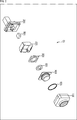
- FIG. 2 is an exploded perspective view of the camera device 10 as viewed from the front side.
- the configuration of the camera apparatus 10 will be described with reference to FIGS. 1 and 2.
- the camera device 10 is mounted on a vehicle and constitutes an in-vehicle camera system.
- the camera device 10 is attached, for example, as a front view camera, a rear view camera, or a side view camera to the front, rear, or side of the vehicle via a dedicated connector.
- the front view camera is provided, for example, in the vicinity of the front grill of the vehicle, and images a region that is a blind spot from the driver in front of the vehicle.
- the front view camera captures an image used in an upper region for displaying a video image (around view monitor (AVM)) as if looking down from above the vehicle.
- AVM around view monitor
- the rear view camera is attached, for example, near the tailgate of the vehicle. Specific mounting positions include the side of the handle portion of the tail gate and the vicinity of the license plate.
- the rear view camera captures an image of a blind spot from the driver behind the vehicle, and also captures an image used in a lower region for displaying an around view monitor (AVM).
- AVM around view monitor
- the side view camera is disposed, for example, in the case of the side mirror or in the vicinity of the side mirror.
- the side view camera captures an image of a blind spot from left and right drivers of the vehicle, and captures images used for the left and right regions for displaying an around view monitor (AVM).
- AVM around view monitor
- the captured image captured by the camera device 10 is basically used for image display purposes in the vehicle interior, but it recognizes objects such as surrounding vehicles, pedestrians, roads (lanes), road signs, It can also be used for other purposes such as recording on a drive recorder.
- the camera device 10 includes a lens barrel 104 in which an imaging lens fitted in a housing 100 including a front case 101 and a rear case 102 is incorporated, and light incident through the imaging lens.
- An image pickup mechanism 106 having an image pickup element for taking A sealing O-ring 103 is attached to the lens barrel 104.
- a dust-proof sheet 105 is provided between the lens barrel 104 and the imaging mechanism 106.
- a shield chassis 107 that blocks unnecessary electromagnetic waves generated inside and outside the camera device 10 is provided in the housing 100.
- the shield chassis 107 is larger than the area of the substrate of the imaging mechanism 106, but is slightly smaller than the housing 100, is disposed along the inner surface of the rear case 102, and covers the periphery of the substrate. Further, the shield chassis 107 is open on both the front surface and the back surface.
- the board of the imaging mechanism 106 and the flexible wiring board (FPC: Flexible Printed Circuits) in the rear case 102 are electrically connected through the opening on the back side of the shield chassis 107.
- the flexible wiring board is also connected to the connector portion on the rear case 102 side, the substrate of the imaging mechanism 106 and the connector portion of the rear case 102 are electrically connected. Note that the substrate of the imaging mechanism 106 is fixed by a spacer 108.
- FIG. 3 shows an exploded perspective view when the camera device 20 is viewed from the front side, as in FIG.
- the camera device 20 is different in model from the camera device 10, but the front case 201 to the spacer 208 in FIG. 3 is basically configured in the same manner as the front case 101 to the spacer 108 in FIG. In the following description, the camera device 10 will be described.
- connectors used for in-vehicle cameras often require severe restrictions on their sizes for the convenience of routing in the vehicle.
- the in-vehicle camera needs to write parameter information via a contact (communication core) at the time of manufacture, but in actual use (at the time of product use), there are surplus contacts used only at the time of manufacture. It will be.
- the length of the core of the contact used in actual use is different from that of the contact used only in manufacturing, and a dedicated jig connector is used during manufacturing.
- the parameter information is written through a contact used only at the time of manufacture.
- the number of contacts (cores) used in actual use can be reduced, so that it is possible to realize a reduction in manufacturing cost due to the reduction in the number of cores and miniaturization of the connector itself.
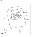
- FIG. 4 is a front view showing the connector portion 121 of the rear case 102.
- the rear case 102 is provided with a connector portion 121 on the connection side (connection target side) with a vehicle connector (vehicle connector 30 in FIG. 10 described later) provided on the vehicle side.
- the connector portion 121 is provided with four actual contacts 141-1 to 141-4 and two manufacturing contacts 142-1 and 142-2.
- the four actual use contacts 141-1 to 141-4 are connected to the connector part on the vehicle connector side (for example, actual use) when the connector part 121 and the vehicle connector are connected in actual use. It is provided at a position corresponding to a concave connector corresponding to the convex shape of the core of the contacts 141-1 to 141-4.
- the actual use contacts 141-1 to 141-4 provided on the connector part 121 of the camera device 10 are fitted and electrically connected to the connector part on the vehicle connector side, Signal is exchanged.
- the two manufacturing contacts 142-1 and 142-2 are arranged on the jig connector side when the connector part 121 and the jig connector (not shown) are connected at the time of manufacture. It is provided at a position corresponding to the terminal to be provided.
- the jig connector is prepared for writing various parameter information to the camera device 10 through the manufacturing contacts 142-1 and 142-2 provided in the connector 121 at the time of manufacturing. It is a dedicated connector and is electrically connected to equipment used at the time of manufacture.
- the manufacturing contacts 142-1 and 142-2 are electrically connected to each other by contacting the terminals of the jig connector, and devices used during manufacturing can write parameter information to the camera device 10. It becomes possible.
- the manufacturing contacts 142-1 and 142-2 of the connector portion 121 in the camera device 10 are connected to and electrically connected to the terminals of the jig connector, and are built in the camera device 10. Parameter information is written to the non-volatile memory.
- parameter information includes, for example, information necessary for imaging. Details of the jig connector will be described later.
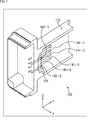
- FIG. 5 shows a perspective view of the connector portion 121 when the rectangular tubular member 122 is removed.
- each of the four actually used contacts 141-1 to 141-4 has the same core length, while two manufacturing contacts.
- Each of 142-1 and 142-2 has the same core length.
- the actually used contacts 141-1 to 141-4 have a longer core length than the manufacturing contacts 142-1 and 142-2, and have different core lengths. Further, if the shapes of the actual contacts 141-1 to 141-4 are compared with the shapes of the contacts 142-1 and 142-2 for manufacturing, those shapes are different.
- the two manufacturing contacts 142-1 and 142-2 are regions excluding the region where the four actual use contacts 141-1 to 141-4 are disposed (-Z in the figure). Are disposed at predetermined intervals.
- the manufacturing contacts 142-1 and 142-2 are in contrast to the four actually used contacts 141-1 to 141-4 arranged side by side in the horizontal direction when viewed from the vehicle connector side to be connected. These are arranged side by side at a predetermined interval in the same horizontal direction.
- the arrangement of the actual use contacts 141-1 to 141-4 is determined by the shape of the connector part on the vehicle connector side, so the actual use contacts 141-1 to 141-4 are arranged.
- the region excluding the region (the remaining region) is used as a region for arranging the manufacturing contacts 142-1 and 142-2.
- the contacts 142-1 and 142-2 for manufacturing are arranged in the remaining region, for example, the strength of the contact (core) can be taken into consideration, and the contacts can be arranged at arbitrary positions. .
- the distance between the actual use contact 141 and the manufacturing contact 142 is considered.
- the ease of making contacts disposed in the connector unit 121 may be considered.
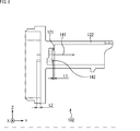
- FIG. 6 shows a cross-sectional view of the connector portion 121 of the rear case 102.
- the vehicle connector is inserted into and fitted into the rectangular tube-shaped member 122 of the rear case 102, whereby the respective connector portions are electrically connected.
- the actual contacts 141-1 to 141-4 are electrically connected to the connector portion on the vehicle connector side, but the manufacturing contacts 142-1 and 142-2 are not electrically connected. It is said.
- the manufacturing contacts 142-1 and 142- The tip of the second core is made to have a distance of length L1 with respect to the tip surface of the vehicle connector. In other words, the tips of the cores of the manufacturing contacts 142-1 and 142-2 do not contact the tip of the vehicle connector during actual use.
- the manufacturing contacts 142-1 and 142-2 also protrude through the connection surface side (the back surface side of the connector portion 121) connected to the flexible board.
- the length of the protruding core is the length L2, and can be a length different from the length L1.
- L2 > L1.
- FIG. 7 is a cross-sectional view including cross sections of manufacturing contacts 142-1 and 142-2 disposed in the connector 121.
- FIG. 8 is a cross-sectional view including the cross sections of the actual use contacts 141-1 to 141-4 disposed in the connector part 121.
- the actual use contacts 141-1 to 141-4 and the manufacturing contacts 142-1 and 142-2 pass through, respectively. Yes.
- the manufacturing contacts 142-1 and 142-2 are actually used contacts 141-1 to 141-4 when viewed from the vehicle connector side (connection target side) provided on the vehicle side. In comparison, the length of the core is shorter.
- the connector portion 121 is provided with two types of contacts, that is, the actual use contact 141 used during actual use and the production contact 142 used only during production. In actual use, it is prevented from being connected to the vehicle connector, while in manufacture, it is in contact with the jig connector connected to the device to be electrically connected.
- the manufacturing cost can be reduced by the amount obtained by multiplying the price per core by the reduced number of cores.
- the connector portion 121 the number of cores of the actual use contacts 141 can be reduced by providing the manufacturing contacts 142. Since the minimum number can be used, the connector itself can be downsized by reducing the number of cores. For example, as described above, a connector used for an in-vehicle camera often requires severe restrictions on its size for the convenience of routing in the vehicle. However, in the camera device 10 (FIG. 1), the vehicle By applying the connector portion 121 as a connector connected to the connector, such a request can be met.
- FIG. 9 shows the structure of the connector portion 921 provided in the current rear case 902. 9, a front view of the connector portion 921 is shown on the left side in the drawing, and a cross-sectional view of the connector portion 921 is shown on the right side in the drawing.
- the contacts 941-1 to 941-6 provided on the connector portion 921 in the rectangular tube-shaped member 922 have the same core shape and the same core length. That is, in the connector portion 921, a contact that is used only at the time of manufacture (in other words, a contact that is not used at the time of actual use) has the same core shape as that of a contact that is used at the time of actual use and has the same core. It is length.
- the contacts 941-1 to 941-6 provided in the connector portion 921 when the contacts 941-4 and 941-6 are used only at the time of manufacture, the contacts 941-4 used only at the time of manufacture.
- 941-6 and contacts 941-1, 941-2, 941-3, and 941-5 used in actual use have the same core shape and the same core length.
- the connector portion 121 is provided with two types of contacts, that is, an actual use contact 141 used during actual use and a production contact 142 used only during production. Therefore, the manufacturing cost is reduced and the size is reduced.
- the number of contacts required for actual use is determined according to the shape of the connector portion on the vehicle connector side, but in the current connector portion 921 described above, four of the six contacts are actual. Although used at the time of use, two are used only at the time of manufacture, and are unnecessary at the time of actual use.
- the four contacts used in actual use are used for the purpose of, for example, ground (GND), video signal, power supply, etc., while the two contacts used only in manufacturing are For example, it is used for communication purposes.
- the number of contacts (number of cores) to be connected in actual use can be reduced from six to four, so that the cost can be reduced.
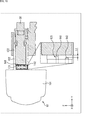
- FIG. 10 is a cross-sectional view showing an example of the structure of the camera device 10 and the vehicle connector 30 during actual use.
- the vehicle connector 30 is inserted into and fitted into a rectangular tube-shaped member 122 formed in the rear case 102 of the camera device 10. Thereby, the connector part 121 provided in the rear case 102 of the camera apparatus 10 and the vehicle connector 30 (connector part) provided in the vehicle are electrically connected.
- FIG 10 shows an enlarged view of the vicinity of the connector portion 121 when the camera device 10 and the vehicle connector 30 are connected. As shown in the enlarged view, among the contacts provided in the connector portion 121 in actual use, the actual use contact 141 is electrically connected to the vehicle connector 30, but the manufacturing contact 142 is electrically connected. Left unconnected.
- the length of the lead is adjusted so that the tip of the lead of the manufacturing contact 142 is separated from the tip surface of the vehicle connector 30 by the length L1. . That is, here, the connector 121 is designed so that it does not interfere with the two manufacturing contacts 142-1 and 142-2 when the vehicle connector 30 is inserted into the rectangular tubular member 122. Is going.
- the manufacturing contacts 142-1 and 142-2 have different core shapes and lengths from the current core, but here, for example, the current core is processed and used. Thus, the manufacturing cost can be further reduced.
- FIG. 11 is a cross-sectional view showing an example of the structure of the actual use contact 141 in actual use.
- FIG. 11 shows an enlarged view of the actual use contact 141-1 among the contacts constituting the connector portion 121.
- a stopper portion 141A and a barb portion 141B are formed on the actual use contact 141-1.
- the actual use contact 141-1 disposed in the connector part 121 is prevented from being recessed by the stopper part 141A. Further, the actual use contacts 141-1 disposed in the connector part 121 can be prevented from coming off the rear case 102 by the barb portions 141B formed at four places.
- the terminal (core) is brought into contact with the manufacturing contacts 142-1 and 142-2 provided in the connector portion 121. It is arranged. Therefore, at the time of manufacturing, among the contacts provided on the connector portion 121, the manufacturing contact 142 is electrically connected to the jig connector. Therefore, parameter information can be written to the camera device 10 by a device used at the time of manufacture.
- terminals (cores) corresponding to the actual use contacts 141-1 to 141-4 provided on the connector portion 121 and the contacts 142-1 and 142-2 for manufacturing are provided.
- the length of the terminal (core) can be changed according to the length of the actual use contact 141 and the manufacturing contact 142 (core).
- Various shapes can be adopted as the shape of the jig connector core.
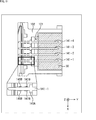
- FIG. 12 is a view showing a first modification of the arrangement of contacts in the connector portion 121.
- the manufacturing contacts 142-1 and 142-2 include the upper region where the actual use contacts 141-1 to 141-3 are provided and the actual use contacts 141-4 to 141-6. Are provided at a predetermined interval in a region (intermediate region) excluding the lower region where is provided.
- the manufacturing contacts 142-1 and 142-2 are actually used contacts 141-1 to 141-3 arranged side by side in the horizontal direction (X direction) in the connector portion 121.
- the actual contacts 141-4 to 141-6 arranged side by side in the horizontal direction are arranged side by side at a predetermined interval in the same horizontal direction.
- the cores of the manufacturing contacts 142-1 and 142-2 are shorter than the cores of the actual contacts 141-1 to 141-6, and are provided for writing parameter information during manufacturing. Is.
- the number of actual contacts 141 can be reduced by providing the manufacturing contacts 142 that are used only during manufacturing, so that the number of actual contacts 141 can be reduced. Manufacturing costs can be reduced.
- the manufacturing contact 142 is disposed in a region other than the region where the actual use contact 141 is disposed, so that a new region for placing the manufacturing contact 142 is secured.
- the connector part 121 can be reduced in size by making the manufacturing contact 142 a contact type. Therefore, not only the manufacturing cost can be reduced, but also the connector itself can be downsized.
- FIG. 13 is a diagram illustrating a second modification of the arrangement of contacts in the connector unit 121.
- the manufacturing contacts 142-1 and 142-2 include the left region where the actual use contacts 141-1 and 141-3 are provided, and the actual use contacts 141-2 and 141-4. Are provided at predetermined intervals in a region (intermediate region) excluding the right region provided with.
- the manufacturing contacts 142-1 and 142-2 are actually used contacts 141-1 and 141-3 arranged in the vertical direction in the middle region in the vertical direction (Y direction) of the connector portion 121.
- the actual contacts 141-2 and 141-4 arranged side by side in the vertical direction are arranged side by side at a predetermined interval in the same vertical direction.
- the number of actual contacts 141 can be reduced by providing the manufacturing contacts 142 that are used only during manufacturing. Manufacturing costs can be reduced.
- the manufacturing contact 142 is disposed in a region other than the region where the actual use contact 141 is disposed. Therefore, a region for arranging the manufacturing contact 142 is newly provided. It is not necessary to secure the connector portion 121, and the connector portion 121 can be reduced in size by making the manufacturing contact 142 a contact type.
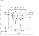
- FIG. 14 is a diagram illustrating a third modification of the arrangement of contacts in the connector portion 121.
- the manufacturing contacts 142-1 and 142-2 and the manufacturing contacts 142-3 and 142-4 are intermediate between the actual use contacts 141-1 to 141-4.
- the upper region and the lower region, which are regions other than the region, are provided at predetermined intervals.
- the manufacturing contacts 142-1 and 142-2 are connected to the actually used contacts 141-1 to 141-4 arranged side by side in the horizontal direction (X direction) upper region of the connector part 121. On the other hand, they are arranged side by side at a predetermined interval in the horizontal direction which is the same direction. Further, the manufacturing contacts 142-3 and 142-4 are actually used contacts 141-1 to 141-4 that are arranged in the horizontal direction in the region below the horizontal direction (X direction) in the connector portion 121. On the other hand, they are arranged side by side at a predetermined interval in the horizontal direction which is the same direction.
- the number of the actual contacts 141 can be reduced by providing the manufacturing contacts 142 that are used only at the time of manufacture. Manufacturing costs can be reduced.
- the manufacturing contact 142 is disposed in a region other than the region in which the actual use contact 141 is disposed. Therefore, a region for arranging the manufacturing contact 142 is newly provided. It is not necessary to secure the connector portion 121, and the connector portion 121 can be reduced in size by making the manufacturing contact 142 a contact type.
- the manufacturing contact 142 is arranged in a region other than the region where the actual use contact 141 is arranged. In this case, for example, other arrangement forms such as two manufacturing contacts 142 are arranged between the two actual use contacts 141 can be adopted.
- the number and arrangement of the actually used contacts 141 are determined according to the shape of the connector portion on the vehicle connector 30 side. Therefore, the connector portion 121 is arranged according to the shape of the connector portion on the vehicle connector 30 side. Based on the arrangement of the actual use contact 141, the manufacturing contact 142 is arranged so as not to obstruct the actual use contact 141.
- the camera device 10 is a connector device including a connector portion 121 provided in the rear case 102.
- the camera device 10 is an example of a connector device including a connector portion 121 having two types of contacts, that is, an actual use contact 141 used during actual use and a production contact 142 used only during production.
- Other electronic devices provided with the connector part 121 can be a connector device to which the present technology is applied.
- the camera device 10 as the first connector device and the vehicle connector 30 (second connector device) connected to the connector portion 121 of the camera device 10 can also be regarded as constituting a connector system.
- the system refers to a logical collection of a plurality of devices.
- the technology (this technology) according to the present disclosure can be applied to various products.
- the technology according to the present disclosure is realized as a device that is mounted on any type of mobile body such as an automobile, an electric vehicle, a hybrid electric vehicle, a motorcycle, a bicycle, personal mobility, an airplane, a drone, a ship, and a robot. May be.
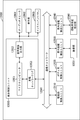
- FIG. 15 is a block diagram illustrating a schematic configuration example of a vehicle control system that is an example of a mobile control system to which the technology according to the present disclosure can be applied.
- the vehicle control system 12000 includes a plurality of electronic control units connected via a communication network 12001.
- the vehicle control system 12000 includes a drive system control unit 12010, a body system control unit 12020, a vehicle exterior information detection unit 12030, a vehicle interior information detection unit 12040, and an integrated control unit 12050.
- a microcomputer 12051, an audio image output unit 12052, and an in-vehicle network I / F (interface) 12053 are illustrated.
- the drive system control unit 12010 controls the operation of the device related to the drive system of the vehicle according to various programs.
- the drive system control unit 12010 includes a driving force generator for generating a driving force of a vehicle such as an internal combustion engine or a driving motor, a driving force transmission mechanism for transmitting the driving force to wheels, and a steering angle of the vehicle. It functions as a control device such as a steering mechanism that adjusts and a braking device that generates a braking force of the vehicle.
- the body system control unit 12020 controls the operation of various devices mounted on the vehicle body according to various programs.
- the body system control unit 12020 functions as a keyless entry system, a smart key system, a power window device, or a control device for various lamps such as a headlamp, a back lamp, a brake lamp, a blinker, or a fog lamp.
- the body control unit 12020 can be input with radio waves transmitted from a portable device that substitutes for a key or signals from various switches.
- the body system control unit 12020 receives input of these radio waves or signals, and controls a door lock device, a power window device, a lamp, and the like of the vehicle.
- the vehicle outside information detection unit 12030 detects information outside the vehicle on which the vehicle control system 12000 is mounted.
- the imaging unit 12031 is connected to the vehicle exterior information detection unit 12030.
- the vehicle exterior information detection unit 12030 causes the imaging unit 12031 to capture an image outside the vehicle and receives the captured image.
- the vehicle outside information detection unit 12030 may perform an object detection process or a distance detection process such as a person, a car, an obstacle, a sign, or a character on a road surface based on the received image.
- the imaging unit 12031 is an optical sensor that receives light and outputs an electrical signal corresponding to the amount of received light.
- the imaging unit 12031 can output an electrical signal as an image, or can output it as distance measurement information. Further, the light received by the imaging unit 12031 may be visible light or invisible light such as infrared rays.
- the vehicle interior information detection unit 12040 detects vehicle interior information.
- a driver state detection unit 12041 that detects a driver's state is connected to the in-vehicle information detection unit 12040.
- the driver state detection unit 12041 includes, for example, a camera that images the driver, and the vehicle interior information detection unit 12040 determines the degree of fatigue or concentration of the driver based on the detection information input from the driver state detection unit 12041. It may be calculated or it may be determined whether the driver is asleep.
- the microcomputer 12051 calculates a control target value of the driving force generator, the steering mechanism, or the braking device based on the information inside / outside the vehicle acquired by the vehicle outside information detection unit 12030 or the vehicle interior information detection unit 12040, and the drive system control unit A control command can be output to 12010.
- the microcomputer 12051 realizes an ADAS (Advanced Driver Assistance System) function including vehicle collision avoidance or impact mitigation, following traveling based on inter-vehicle distance, vehicle speed maintaining traveling, vehicle collision warning, or vehicle lane departure warning, etc. It is possible to perform cooperative control for the purpose.
- ADAS Advanced Driver Assistance System
- the microcomputer 12051 controls the driving force generator, the steering mechanism, the braking device, and the like based on the information around the vehicle acquired by the vehicle exterior information detection unit 12030 or the vehicle interior information detection unit 12040. It is possible to perform cooperative control for the purpose of automatic driving that autonomously travels without depending on the operation.
- the microcomputer 12051 can output a control command to the body system control unit 12020 based on information outside the vehicle acquired by the vehicle outside information detection unit 12030.
- the microcomputer 12051 controls the headlamp according to the position of the preceding vehicle or the oncoming vehicle detected by the outside information detection unit 12030, and performs cooperative control for the purpose of anti-glare, such as switching from a high beam to a low beam. It can be carried out.
- the sound image output unit 12052 transmits an output signal of at least one of sound and image to an output device capable of visually or audibly notifying information to a vehicle occupant or the outside of the vehicle.
- an audio speaker 12061, a display unit 12062, and an instrument panel 12063 are illustrated as output devices.
- the display unit 12062 may include at least one of an on-board display and a head-up display, for example.
- FIG. 16 is a diagram illustrating an example of an installation position of the imaging unit 12031.
- the vehicle 12100 includes imaging units 12101, 12102, 12103, 12104, and 12105 as the imaging unit 12031.
- the imaging units 12101, 12102, 12103, 12104, and 12105 are provided, for example, at positions such as a front nose, a side mirror, a rear bumper, a back door, and an upper part of a windshield in the vehicle interior of the vehicle 12100.
- the imaging unit 12101 provided in the front nose and the imaging unit 12105 provided in the upper part of the windshield in the vehicle interior mainly acquire an image in front of the vehicle 12100.
- the imaging units 12102 and 12103 provided in the side mirror mainly acquire an image of the side of the vehicle 12100.
- the imaging unit 12104 provided in the rear bumper or the back door mainly acquires an image behind the vehicle 12100.
- the forward images acquired by the imaging units 12101 and 12105 are mainly used for detecting a preceding vehicle or a pedestrian, an obstacle, a traffic light, a traffic sign, a lane, or the like.
- FIG. 16 shows an example of the shooting range of the imaging units 12101 to 12104.
- the imaging range 12111 indicates the imaging range of the imaging unit 12101 provided in the front nose
- the imaging ranges 12112 and 12113 indicate the imaging ranges of the imaging units 12102 and 12103 provided in the side mirrors, respectively
- the imaging range 12114 The imaging range of the imaging part 12104 provided in the rear bumper or the back door is shown. For example, by superimposing the image data captured by the imaging units 12101 to 12104, an overhead image when the vehicle 12100 is viewed from above is obtained.
- At least one of the imaging units 12101 to 12104 may have a function of acquiring distance information.
- at least one of the imaging units 12101 to 12104 may be a stereo camera including a plurality of imaging elements, or may be an imaging element having pixels for phase difference detection.
- the microcomputer 12051 based on the distance information obtained from the imaging units 12101 to 12104, the distance to each three-dimensional object in the imaging range 12111 to 12114 and the temporal change in this distance (relative speed with respect to the vehicle 12100).
- a predetermined speed for example, 0 km / h or more
- the microcomputer 12051 can set an inter-vehicle distance to be secured in advance before the preceding vehicle, and can perform automatic brake control (including follow-up stop control), automatic acceleration control (including follow-up start control), and the like.
- automatic brake control including follow-up stop control
- automatic acceleration control including follow-up start control
- cooperative control for the purpose of autonomous driving or the like autonomously traveling without depending on the operation of the driver can be performed.
- the microcomputer 12051 converts the three-dimensional object data related to the three-dimensional object to other three-dimensional objects such as a two-wheeled vehicle, a normal vehicle, a large vehicle, a pedestrian, and a utility pole based on the distance information obtained from the imaging units 12101 to 12104. It can be classified and extracted and used for automatic avoidance of obstacles.
- the microcomputer 12051 identifies obstacles around the vehicle 12100 as obstacles that are visible to the driver of the vehicle 12100 and obstacles that are difficult to see.
- the microcomputer 12051 determines the collision risk indicating the risk of collision with each obstacle, and when the collision risk is equal to or higher than the set value and there is a possibility of collision, the microcomputer 12051 is connected via the audio speaker 12061 or the display unit 12062. By outputting an alarm to the driver and performing forced deceleration or avoidance steering via the drive system control unit 12010, driving assistance for collision avoidance can be performed.
- At least one of the imaging units 12101 to 12104 may be an infrared camera that detects infrared rays.
- the microcomputer 12051 can recognize a pedestrian by determining whether a pedestrian is present in the captured images of the imaging units 12101 to 12104. Such pedestrian recognition is, for example, whether or not the user is a pedestrian by performing a pattern matching process on a sequence of feature points indicating the outline of an object and a procedure for extracting feature points in the captured images of the imaging units 12101 to 12104 as infrared cameras. It is carried out by the procedure for determining.
- the audio image output unit 12052 When the microcomputer 12051 determines that there is a pedestrian in the captured images of the imaging units 12101 to 12104 and recognizes the pedestrian, the audio image output unit 12052 has a rectangular contour line for emphasizing the recognized pedestrian.
- the display unit 12062 is controlled so as to be superimposed and displayed.
- voice image output part 12052 may control the display part 12062 so that the icon etc. which show a pedestrian may be displayed on a desired position.
- the technology according to the present disclosure can be applied to the imaging unit 12031 among the configurations described above.
- the camera device 10 can be applied to the imaging units 12101, 12102, 12103, 12104, and 12105 as the imaging unit 12031. That is, the imaging unit 12101 in FIG. 16 corresponds to the above-described front view camera, the imaging units 12102 and 12103 in FIG. 16 correspond to the above-described side view camera, and the imaging unit 12104 in FIG. This corresponds to the rear view camera described above, and is connected to a vehicle connector provided on the vehicle 12100.
- the connection portion with the vehicle connector can be further downsized.
- the present technology can take the following configurations.
- the first contact is electrically connected to a connector to be connected; The connector device according to any one of (1) to (3), wherein the second contact is not electrically connected to a connector to be connected.
- the second contact is electrically connected to a device used at the time of manufacture through a connector to be connected that is configured to be electrically connectable to the second contact.
- the connector apparatus in any one of. (6) The connector device according to (5), wherein the second contact is electrically connected by contacting a connector to be connected. (7)
- the one or more first contacts and the one or more second contacts are provided in a connector portion formed of a predetermined region when viewed from the connection target side, The one or more second contacts are provided in a region other than a region where the one or more first contacts are provided in a predetermined region.
- Connector device. (8)
- the plurality of second contacts are provided side by side in the horizontal direction or the vertical direction with respect to the plurality of first contacts provided in the horizontal direction or the vertical direction when viewed from the connection target side. (7)
- the connector apparatus as described in.
- the connector device includes a camera device having an imaging function, The said camera apparatus is electrically connected with the vehicle connector provided in the vehicle.
- the connector apparatus as described in said (1) thru
- a connector system comprising a first connector device and a second connector device, The first connector device includes: A first contact used in actual use; A second contact used only during manufacture, The first contact and the second contact have different core lengths when viewed from the connection target side, The second connector device includes a connection portion corresponding to the first contact.
Landscapes
- Engineering & Computer Science (AREA)
- Multimedia (AREA)
- Signal Processing (AREA)
- Studio Devices (AREA)
- Coupling Device And Connection With Printed Circuit (AREA)
- Traffic Control Systems (AREA)
Abstract
本技術は、製造コストの低下を実現することができるようにするコネクタ装置、及びコネクタシステムに関する。 実使用時に使用される第1のコンタクトと、製造時にのみ使用される第2のコンタクトとを備え、第1のコンタクトと、第2のコンタクトとは、その接続対象側から見た場合の芯の長さが異なるコネクタ装置が提供される。本技術は、例えば、車両コネクタと電気的に接続されるカメラ装置に適用することができる。
Description
本技術は、コネクタ装置、及びコネクタシステムに関し、特に、製造コストの低下を実現することができるようにしたコネクタ装置、及びコネクタシステムに関する。
近年、カメラを搭載する自動車が増えてきている。例えば、車載カメラにより撮像された画像は、車室内のモニタ画面で運転者やその他の搭乗者に見せたり、ドライブレコーダに記録したりすることができる。
また、車載カメラにより撮像された画像に対して画像認識などの画像処理を適用して、道路の白線(レーン)や信号機、道路標識、対向車、自車両周辺の歩行者などを検出し、その検出結果に基づき、走行支援や視界支援を行うことができる。
車載カメラは、例えば、フロント・ビュー・カメラや、リア・ビュー・カメラ、サイド・ビュー・カメラとして、車両の前方や後方、側方に、専用のコネクタを介して取り付けられる。専用のコネクタを用いることで、製造時に、車載カメラの取り付けを、容易に行うことが可能となる。コネクタに関する技術としては、例えば、特許文献1に開示されている技術が知られている。
ところで、車載カメラに用いられるコネクタは、車両内の引き回しの都合上、そのサイズに厳しい制約が求められる場合が多い。また、車載カメラは、製造時に、コンタクト(通信芯)を介してパラメータ情報を書き込む必要があるが、実使用時(製品使用時)には、製造時にのみ使用されたコンタクトが余剰に存在することになる。
このように、コネクタにおいて、実使用時に不要なコンタクトが存在していると、製造コストの増加にもつながってしまう。
本技術はこのような状況に鑑みてなされたものであり、コネクタが設けられた車載カメラ等のコネクタ装置において、製造コストの低下を実現することができるようにするものである。
本技術の一側面のコネクタ装置は、実使用時に使用される第1のコンタクトと、製造時にのみ使用される第2のコンタクトとを備え、前記第1のコンタクトと、前記第2のコンタクトとは、その接続対象側から見た場合の芯の長さが異なるコネクタ装置である。
本技術の一側面のコネクタ装置においては、実使用時に使用される第1のコンタクトと、製造時にのみ使用される第2のコンタクトとが、その接続対象側から見た場合の芯の長さが異なるように形成される。
本技術の一側面のコネクタシステムは、第1のコネクタ装置と第2のコネクタ装置とから構成されるコネクタシステムであって、前記第1のコネクタ装置は、実使用時に使用される第1のコンタクトと、製造時にのみ使用される第2のコンタクトとを備え、前記第1のコンタクトと、前記第2のコンタクトとは、その接続対象側から見た場合の芯の長さが異なり、前記第2のコネクタ装置は、前記第1のコンタクトに対応した接続部を備えるコネクタシステムである。
本技術の一側面のコネクタシステムにおいては、第1のコネクタ装置において、実使用時に使用される第1のコンタクトと、製造時にのみ使用される第2のコンタクトとが、その接続対象側から見た場合の芯の長さが異なるように形成され、第2のコネクタ装置において、第1のコンタクトに対応した接続部が設けられる。
本技術の一側面によれば、製造コストの低下を実現することができる。
なお、ここに記載された効果は必ずしも限定されるものではなく、本開示中に記載されたいずれかの効果であってもよい。
以下、図面を参照しながら本技術の実施の形態について説明する。なお、説明は以下の順序で行うものとする。
1.本技術の概要
2.本技術を適用したコネクタ部の構造
3.接続時のコネクタ部の構造
4.変形例
5.移動体への応用例
2.本技術を適用したコネクタ部の構造
3.接続時のコネクタ部の構造
4.変形例
5.移動体への応用例
<1.本技術の概要>
図1は、カメラ装置10を示す斜視図を示している。また、図2には、カメラ装置10を前面側から見た場合の分解斜視図を示している。以下、図1及び図2を参照しながら、カメラ装置10の構成について説明する。
カメラ装置10は、車両に搭載され、車載カメラシステムを構成する。カメラ装置10は、例えば、フロント・ビュー・カメラや、リア・ビュー・カメラ、サイド・ビュー・カメラとして、車両の前方や後方、側方に、専用のコネクタを介して取り付けられる。
ここで、フロント・ビュー・カメラは、例えば車両のフロント・グリル近傍に設けられ、車両前方の運転者から死角となる領域を撮像する。また、フロント・ビュー・カメラは、車両上方から見下ろしたような感覚の映像(アラウンドビューモニタ(AVM))を表示するための上方領域に用いられる画像を撮像する。
リア・ビュー・カメラは、例えば、車両のテール・ゲート付近に取り付けられる。具体的な取り付け位置としては、テール・ゲートのハンドル部分の横や、ナンバープレート近傍を挙げることができる。リア・ビュー・カメラは、車両後方の運転者から死角となる領域を撮像し、また、アラウンドビューモニタ(AVM)を表示するための下方領域に用いられる画像を撮像する。
サイド・ビュー・カメラは、例えばサイドミラーの筐体内、又はサイドミラー近傍に配置される。サイド・ビュー・カメラは、車両の左右の運転者から死角となる領域を撮像し、また、アラウンドビューモニタ(AVM)を表示するための左右の各領域に用いられる画像を撮像する。
カメラ装置10により撮像された撮像画像は、基本的には車室内での画像表示目的で使用されるが、周辺車両や歩行者、道路(レーン)、道路標識などの物体認識(センシング)や、ドライブレコーダへの記録など、その他の目的に使用することもできる。
ここで、図2に示すように、カメラ装置10は、フロントケース101とリアケース102からなるハウジング100に嵌合された撮像レンズが組み込まれたレンズバレル104と、撮像レンズを介して入射した光を取り込む撮像素子を有する撮像機構106を備えている。なお、レンズバレル104に対し、密封用のOリング103が取り付けられる。また、レンズバレル104と撮像機構106との間には、防塵対策用のシート105が設けられる。
さらに、ハウジング100内には、カメラ装置10の内外で発生する不要な電磁波を遮断するシールドシャーシ107が設けられる。このシールドシャーシ107は、撮像機構106の基板の面積よりも大きいが、ハウジング100よりも一回り小さく、リアケース102の内面に沿うように配設され、基板の周囲を覆っている。また、シールドシャーシ107は、前面と背面がともに開口されている。
これにより、シールドシャーシ107の背面側の開口を介して、撮像機構106の基板と、リアケース102内のフレキシブル配線基板(FPC:Flexible Printed Circuits)とが電気的に接続される。また、このフレキシブル配線基板は、リアケース102側のコネクタ部とも接続されているため、撮像機構106の基板と、リアケース102のコネクタ部とが電気的に接続されることになる。なお、撮像機構106の基板は、スペーサ108により固定される。
なお、図3には、図2と同様に、カメラ装置20を前面側から見た場合の分解斜視図を示している。カメラ装置20は、カメラ装置10とは型式が異なっているが、図3のフロントケース201ないしスペーサ208は、図2のフロントケース101ないしスペーサ108と基本的に同様に構成される。以下の説明では、カメラ装置10について説明する。
ところで、車載カメラに用いられるコネクタは、車両内の引き回しの都合上、そのサイズに厳しい制約が求められる場合が多い。一方で、車載カメラは、製造時に、コンタクト(通信芯)を介してパラメータ情報を書き込む必要があるが、実使用時(製品使用時)には、製造時にのみ使用されたコンタクトが余剰に存在することになる。
このように、コネクタにおいて、実使用時に不要なコンタクトが存在していると、製造コストの増加にもつながってしまう。また、実使用時に不要なコンタクトが存在していると、サイズの拡大の一因にもなる。
そこで、本開示に係る技術(本技術)では、実使用時に使用されるコンタクトと、製造時にのみ使用されるコンタクトとの芯の長さが異なるようにし、製造時には専用の治具コネクタを使用して、製造時にのみ使用されるコンタクトを介してパラメータ情報が書き込まれるようにする。これにより、実使用時に使用されるコンタクト(の芯)の数を削減することができるため、芯数の削減による製造コストの低下と、コネクタ自体の小型化を実現することが可能となる。
なお、以下の説明では、実使用時に使用されるコンタクトを、「実使用コンタクト」と称する一方で、製造時にのみ使用されるコンタクトを、「製造時用コンタクト」と称して区別するものとする。
<2.本技術を適用したコネクタ部の構造>
(コネクタ部の構造)
次に、図4ないし図8を参照して、リアケース102に設けられるコネクタ部121の構造について説明する。
次に、図4ないし図8を参照して、リアケース102に設けられるコネクタ部121の構造について説明する。
図4は、リアケース102のコネクタ部121を示す正面図である。図4において、リアケース102には、車両側に設けられる車両コネクタ(後述する図10の車両コネクタ30)との接続側(接続対象側)に、コネクタ部121が配設されている。コネクタ部121には、4本の実使用コンタクト141-1ないし141-4と、2本の製造時用コンタクト142-1,142-2とが配設されている。
すなわち、コネクタ部121において、4本の実使用コンタクト141-1ないし141-4は、実使用時にコネクタ部121と車両コネクタとが接続する際に、当該車両コネクタ側のコネクタ部(例えば、実使用コンタクト141-1ないし141-4の芯の凸形状に対応した凹形状のコネクタ)に対応した位置に設けられる。
これによって、実使用時においては、カメラ装置10におけるコネクタ部121に設けられた実使用コンタクト141-1ないし141-4が、車両コネクタ側のコネクタ部に嵌合されて電気的に接続され、各種の信号がやりとりされる。
また、コネクタ部121において、2本の製造時用コンタクト142-1,142-2は、製造時にコネクタ部121と治具コネクタ(不図示)とが接続する際に、当該治具コネクタ側に配設される端子に対応した位置に設けられる。
ここで、治具コネクタは、製造時に、コネクタ部121に設けられた製造時用コンタクト142-1,142-2を介して、カメラ装置10に対し、各種のパラメータ情報を書き込むために用意される専用のコネクタであって、製造時に用いられる機器と電気的に接続される。
なお、製造時用コンタクト142-1,142-2は、治具コネクタの端子と接触することで、電気的に接続され、カメラ装置10に対し、製造時に用いられる機器がパラメータ情報を書き込むことが可能となる。
これによって、製造時においては、カメラ装置10におけるコネクタ部121の製造時用コンタクト142-1,142-2が、治具コネクタの端子に接続されて電気的に接続され、カメラ装置10に内蔵された不揮発性メモリに対し、パラメータ情報が書き込まれる。
なお、パラメータ情報としては、例えば、撮像を行うために必要となる情報などが含まれる。また、治具コネクタの詳細な内容については、後述する。
また、リアケース102において、コネクタ部121の周囲には、車両コネクタの形状に応じた角筒状の部材122が設けられている。この角筒状の部材122を取り除いたときのコネクタ部121の斜視図を示すと、図5に示すようになる。
図5においては、コネクタ部121に設けられるコンタクトのうち、4本の実使用コンタクト141-1ないし141-4のそれぞれは、芯の長さが同一となる一方で、2本の製造時用コンタクト142-1,142-2のそれぞれは、芯の長さが同一となっている。
すなわち、実使用コンタクト141-1ないし141-4は、製造時用コンタクト142-1,142-2よりも、芯の長さが長くなっており、芯の長さが異なっている。また、実使用コンタクト141-1ないし141-4の形状と、製造時用コンタクト142-1,142-2の形状を比べれば、それらの形状は異なっている。
コネクタ部121において、2本の製造時用コンタクト142-1,142-2は、4本の実使用コンタクト141-1ないし141-4が配設された領域を除いた領域(図中の-Z側の領域)に、所定の間隔で配設される。
すなわち、製造時用コンタクト142-1,142-2は、接続対象となる車両コネクタ側から見た場合の水平方向に並んで配置される4本の実使用コンタクト141-1ないし141-4に対し、同一方向となる水平方向に、所定の間隔で並んで配置されている。
このように、コネクタ部121において、実使用コンタクト141-1ないし141-4の配置は、車両コネクタ側のコネクタ部の形状によって決まってしまうので、実使用コンタクト141-1ないし141-4が配置された領域を除いた領域(残りの領域)を、製造時用コンタクト142-1,142-2を配置するための領域として用いている。
なお、残りの領域に対し、製造時用コンタクト142-1,142-2を配置する際には、例えば、コンタクト(の芯)の強度などを考慮して、任意の位置に配置することができる。
ここでは、例えば、コネクタ部121を加工する際に用いられる材料を考慮して(例えば防水用のポッティング材料の流れやすさを考慮して)、実使用コンタクト141と製造時用コンタクト142との間隔を設計することができる。また、例えば、コネクタ部121に配設されるコンタクトの作りやすさなどを考慮するようにしてもよい。
ここで、図6には、リアケース102のコネクタ部121の断面図を示している。図6においては、リアケース102の角筒状の部材122に対し、車両コネクタが挿入され、嵌合されることで、互いのコネクタ部が電気的に接続される。このとき、車両コネクタ側のコネクタ部に対し、実使用コンタクト141-1ないし141-4は、電気的に接続されるが、製造時用コンタクト142-1,142-2は、電気的に未接続とされる。
具体的には、図6に示すように、リアケース102の部材122と車両コネクタが嵌合され、互いのコネクタ部が電気的に接続された場合に、製造時用コンタクト142-1,142-2の芯の先端が、車両コネクタの先端面に対し、長さL1だけ距離を有するようにする。つまり、実使用時において、製造時用コンタクト142-1,142-2の芯の先端が、車両コネクタの先端面に接触することはない。
なお、リアケース102内で、フレキシブル基板と接続される接続面側(コネクタ部121の裏面側)にも、製造時用コンタクト142-1,142-2は、貫通して突き出しているが、その突き出している芯の長さは、長さL2とされ、長さL1とは異なる長さとすることができる。
ただし、L2 > L1とすることができる。また、車両コネクタの形状などにも影響を受けるが、L1の長さとしては、製造時用コンタクト142が、実使用時に邪魔にならないようにするために、可能な限り長さを確保することが望ましい。例えば、L1 = 0.5mmとし、L2 = 1.2mmとすることができる。
また、図7には、コネクタ部121に配設される製造時用コンタクト142-1,142-2の断面を含む断面図を示している。また、図8には、コネクタ部121に配設される実使用コンタクト141-1ないし141-4の断面を含む断面図を示している。
これらの断面図に示すように、リアケース102に設けられたコネクタ部121においては、実使用コンタクト141-1ないし141-4、及び製造時用コンタクト142-1,142-2がそれぞれ貫通している。そして、コネクタ部121において、製造時用コンタクト142-1,142-2は、車両側に設けられる車両コネクタ側(接続対象側)から見た場合に、実使用コンタクト141-1ないし141-4と比べて、芯の長さが短くなっている。
以上のように、コネクタ部121においては、実使用時に使用される実使用コンタクト141と、製造時にのみ使用される製造時用コンタクト142との2種類のコンタクトを設けて、製造時用コンタクト142は、実使用時に、車両コネクタと接続されないようにする一方で、製造時には、機器と接続された治具コネクタと接触して電気的に接続されるようにしている。
そのため、コネクタ部121における実使用コンタクト141の芯の数を、必要最低限の数とすることができるため、芯数の削減による製造コストの低下を実現することができる。ここでは、例えば、芯一本当たりの価格に対し、削減された芯数を乗じて求められる価格の分だけ、製造コストを下げることができる。
また、実使用時に不要なコンタクトが存在していると、サイズの拡大の一因になるが、コネクタ部121においては、製造時用コンタクト142を設けることで、実使用コンタクト141の芯の数を、必要最低限の数とすることができるため、芯数の削減によって、コネクタ自体の小型化を実現することができる。例えば、車載カメラに用いられるコネクタは、車両内の引き回しの都合上、そのサイズに厳しい制約が求められる場合が多いことは先に述べた通りであるが、カメラ装置10(図1)において、車両コネクタと接続されるコネクタとして、コネクタ部121を適用することで、そのような要求にも応えることができる。
ここで、比較のために、図9には、現状のリアケース902に設けられたコネクタ部921の構造を示している。図9においては、図中の左側に、コネクタ部921の正面図を示し、図中の右側に、コネクタ部921の断面図を示している。
図9において、角筒状の部材922内のコネクタ部921に設けられるコンタクト941-1ないし941-6は、芯の形状が同一で、かつ、芯の長さも同一となっている。すなわち、コネクタ部921においては、製造時のみ使用されるコンタクト(言い換えれば、実使用時には使用されないコンタクト)が、実使用時に使用されるコンタクトと、同一の芯の形状で、かつ、同一の芯の長さとなっている。
例えば、コネクタ部921に設けられるコンタクト941-1ないし941-6のうち、コンタクト941-4とコンタクト941-6が、製造時のみ使用される場合に、製造時のみ使用されるコンタクト941-4,941-6と、実使用時に使用されるコンタクト941-1,941-2,941-3,941-5とは、芯の形状が同一で、かつ、芯の長さも同一となる。
このように、コネクタ部921において、実使用時に不要なコンタクト941-4,941-6が存在していると、製造コストの増加に加えて、サイズの拡大の一因になることは先に述べた通りである。そのため、本開示に係る技術(本技術)では、コネクタ部121において、実使用時に使用される実使用コンタクト141と、製造時にのみ使用される製造時用コンタクト142との2種類のコンタクトを設けることで、製造コストの低下と、小型化を図っているのである。
例えば、実使用時に必要となるコンタクトの数は、車両コネクタ側のコネクタ部の形状に応じて決定されるが、上述した現状のコネクタ部921においては、6本のコンタクトのうち、4本が実使用時に使用されるが、2本が製造時にのみ使用され、実使用時には不要とされる。ここで、実使用時に使用される4本のコンタクトは、例えば、グランド(GND)用やビデオ信号用、電源用等の目的で使用される一方で、製造時にのみ使用される2本のコンタクトは、例えば、通信用等の目的で使用される。このような場合に、本技術を適用すれば、実使用時に接続されるコンタクトの数(芯数)を、6本から4本に減らすことができるため、コストを削減することができる。
<3.接続時のコネクタ部の構造>
(実使用時のコネクタ部の構造)
図10は、実使用時におけるカメラ装置10と車両コネクタ30の構造の例を示す断面図である。
図10は、実使用時におけるカメラ装置10と車両コネクタ30の構造の例を示す断面図である。
図10において、車両コネクタ30は、カメラ装置10のリアケース102に形成された角筒状の部材122に対して挿入され、嵌合されている。これにより、カメラ装置10のリアケース102に設けられたコネクタ部121と、車両に設けられた車両コネクタ30(のコネクタ部)とが電気的に接続される。
また、図10においては、カメラ装置10と車両コネクタ30との接続時におけるコネクタ部121付近の拡大図が示されている。この拡大図に示すように、実使用時において、コネクタ部121に設けられたコンタクトのうち、実使用コンタクト141は、車両コネクタ30と電気的に接続されるが、製造時用コンタクト142は、電気的に未接続とされる。
このとき、製造時用コンタクト142の芯の先端が、車両コネクタ30の先端面に対し、長さL1だけ離れるように、芯の長さを調整しているのは、先に述べた通りである。つまり、ここでは、角筒状の部材122に対し、車両コネクタ30が挿入される際に、2本の製造時用コンタクト142-1,142-2と干渉しないように、コネクタ部121の設計を行っている。
なお、本技術において、製造時用コンタクト142-1,142-2は、その芯の形状や長さが、現行の芯とは異なるが、ここでは、例えば、現行の芯を加工して流用することで、製造コストをさらに低下させることができる。
(実使用時の実使用コンタクトの構造)
図11は、実使用時における実使用コンタクト141の構造の例を示す断面図である。
図11は、実使用時における実使用コンタクト141の構造の例を示す断面図である。
図11においては、コネクタ部121を構成するコンタクトのうち、実使用コンタクト141-1の拡大図が示されている。この拡大図に示すように、実使用コンタクト141-1には、ストッパ部141Aとかえし部141Bが形成されている。コネクタ部121に配設される実使用コンタクト141-1は、ストッパ部141Aにより奥抜けが防止される。また、コネクタ部121に配設される実使用コンタクト141-1は、4箇所に形成されたかえし部141Bによって、リアケース102から抜けるのを防止することができる。
なお、現行のコンタクトには、ストッパ部やかえし部が形成されているものがあるが、本技術では、そのようなストッパ部やかえし部を有するコンタクトをそのまま流用することができる。また、図11の拡大図では、実使用コンタクト141-1の構造を一例に説明したが、他の実使用コンタクト141-2ないし141-4についても同様の構造を有している。さらに、図11の拡大図では、かえし部141Bが4箇所(両サイドに2箇所ずつ)に形成された場合を一例に説明したが、かえし部141Bの個数や取り付け位置は、任意である。
(製造時のコネクタ部の構造)
なお、図示はしていないが、製造時においては、製造時に用いられる機器が接続された治具コネクタが、カメラ装置10のリアケース102に形成された角筒状の部材122に対して挿入される。これにより、カメラ装置10のリアケース102に設けられたコネクタ部121と、治具コネクタとが電気的に接続される。
なお、図示はしていないが、製造時においては、製造時に用いられる機器が接続された治具コネクタが、カメラ装置10のリアケース102に形成された角筒状の部材122に対して挿入される。これにより、カメラ装置10のリアケース102に設けられたコネクタ部121と、治具コネクタとが電気的に接続される。
例えば、治具コネクタは、角筒状の部材122に挿入されたときに、コネクタ部121に設けられた製造時用コンタクト142-1,142-2に対して接触するように端子(芯)が配設されている。したがって、製造時において、コネクタ部121に設けられたコンタクトのうち、製造時用コンタクト142は、治具コネクタと電気的に接続される。そのため、製造時に用いられる機器によって、カメラ装置10に対し、パラメータ情報を書き込むことが可能となる。
より具体的には、治具コネクタにおいては、コネクタ部121に設けられた実使用コンタクト141-1ないし141-4と、製造時用コンタクト142-1,142-2に対応して、端子(芯)を配設することができる。そして、治具コネクタにおいては、例えば、実使用コンタクト141と製造時用コンタクト142(の芯)の長さに応じて、端子(芯)の長さを変えることができる。また、治具コネクタの芯の形状としては、様々な形状を採用することができる。
<4.変形例>
(コンタクト配置の第1の変形例)
図12は、コネクタ部121におけるコンタクトの配置の第1の変形例を示す図である。
図12は、コネクタ部121におけるコンタクトの配置の第1の変形例を示す図である。
図12のコネクタ部121において、製造時用コンタクト142-1,142-2は、実使用コンタクト141-1ないし141-3が設けられた上側の領域と、実使用コンタクト141-4ないし141-6が設けられた下側の領域とを除いた領域(中間の領域)に、所定の間隔で設けられる。
すなわち、製造時用コンタクト142-1,142-2は、コネクタ部121における水平方向(X方向)の中間の領域において、水平方向に並んで配置される実使用コンタクト141-1ないし141-3と、水平方向に並んで配置される実使用コンタクト141-4ないし141-6に対し、同一方向となる水平方向に、所定の間隔で並んで配置される。
図12のコネクタ部121において、製造時用コンタクト142-1,142-2の芯は、実使用コンタクト141-1ないし141-6の芯よりも短く、製造時にパラメータ情報を書き込むために設けられたものである。
このように、図12のコネクタ部121においては、製造時にしか使用しない製造時用コンタクト142を設けることで、実使用コンタクト141の数を減らすことができるので、実使用コンタクト141の削減数に応じて製造コストを低下させることができる。
また、図12のコネクタ部121において、製造時用コンタクト142は、実使用コンタクト141が配置される領域以外の領域に配置されるため、製造時用コンタクト142を配置するための領域を新たに確保する必要がなく、また、製造時用コンタクト142を接触式とすることで、コネクタ部121を小型化することができる。よって、製造コストの低下だけでなく、コネクタ自体の小型化を図ることができる。
(コンタクト配置の第2の変形例)
図13は、コネクタ部121におけるコンタクトの配置の第2の変形例を示す図である。
図13は、コネクタ部121におけるコンタクトの配置の第2の変形例を示す図である。
図13のコネクタ部121において、製造時用コンタクト142-1,142-2は、実使用コンタクト141-1,141-3が設けられた左側の領域と、実使用コンタクト141-2,141-4が設けられた右側の領域と除いた領域(中間の領域)に、所定の間隔で設けられる。
すなわち、製造時用コンタクト142-1,142-2は、コネクタ部121における垂直方向(Y方向)の中間の領域において、垂直方向に並んで配置される実使用コンタクト141-1,141-3と、垂直方向に並んで配置される実使用コンタクト141-2,141-4に対し、同一方向となる垂直方向に、所定の間隔で並んで配置される。
このように、図13のコネクタ部121においては、製造時にしか使用しない製造時用コンタクト142を設けることで、実使用コンタクト141の数を減らすことができるので、実使用コンタクト141の削減数に応じて製造コストを低下させることができる。
また、図13のコネクタ部121においても、製造時用コンタクト142は、実使用コンタクト141が配置される領域以外の領域に配置されるため、製造時用コンタクト142を配置するための領域を新たに確保する必要がなく、また、製造時用コンタクト142を接触式とすることで、コネクタ部121を小型化することができる。
(コンタクト配置の第3の変形例)
図14は、コネクタ部121におけるコンタクトの配置の第3の変形例を示す図である。
図14は、コネクタ部121におけるコンタクトの配置の第3の変形例を示す図である。
図14のコネクタ部121において、製造時用コンタクト142-1,142-2と、製造時用コンタクト142-3,142-4は、実使用コンタクト141-1ないし141-4が設けられた中間の領域を除いた領域である、上側の領域と下側の領域にそれぞれ、所定の間隔で設けられる。
すなわち、製造時用コンタクト142-1,142-2は、コネクタ部121における水平方向(X方向)の上側の領域において、水平方向に並んで配置される実使用コンタクト141-1ないし141-4に対し、同一方向となる水平方向に、所定の間隔で並んで配置される。また、製造時用コンタクト142-3,142-4は、コネクタ部121における水平方向(X方向)の下側の領域において、水平方向に並んで配置される実使用コンタクト141-1ないし141-4に対し、同一方向となる水平方向に、所定の間隔で並んで配置される。
このように、図14のコネクタ部121においては、製造時にしか使用しない製造時用コンタクト142を設けることで、実使用コンタクト141の数を減らすことができるので、実使用コンタクト141の削減数に応じて製造コストを低下させることができる。
また、図14のコネクタ部121においても、製造時用コンタクト142は、実使用コンタクト141が配置される領域以外の領域に配置されるため、製造時用コンタクト142を配置するための領域を新たに確保する必要がなく、また、製造時用コンタクト142を接触式とすることで、コネクタ部121を小型化することができる。
(コンタクト配置の他の変形例)
なお、図12ないし図14に示したコンタクトの配置の形態は一例であって、コネクタ部121において、製造時用コンタクト142が、実使用コンタクト141が配置される領域以外の領域に配置されるようにすれば、例えば、2本の実使用コンタクト141の間に、2本の製造時用コンタクト142が配置されるようにするなど、他の配置の形態を採用することができる。
なお、図12ないし図14に示したコンタクトの配置の形態は一例であって、コネクタ部121において、製造時用コンタクト142が、実使用コンタクト141が配置される領域以外の領域に配置されるようにすれば、例えば、2本の実使用コンタクト141の間に、2本の製造時用コンタクト142が配置されるようにするなど、他の配置の形態を採用することができる。
実際には、実使用コンタクト141の本数や配置は、車両コネクタ30側のコネクタ部の形状に応じて決まるため、コネクタ部121においては、車両コネクタ30側のコネクタ部の形状に応じて配置される実使用コンタクト141の配置に基づき、実使用コンタクト141の邪魔にならないように、製造時用コンタクト142が配置されることになる。
(コネクタ装置の例)
カメラ装置10は、そのリアケース102に設けられるコネクタ部121を備えるコネクタ装置であると言える。また、カメラ装置10は、実使用時に使用される実使用コンタクト141と、製造時にのみ使用される製造時用コンタクト142との2種類のコンタクトを有するコネクタ部121を備えるコネクタ装置の一例であって、コネクタ部121を設けた他の電子機器(カメラ装置10以外の電子機器)を、本技術を適用したコネクタ装置とすることができる。
カメラ装置10は、そのリアケース102に設けられるコネクタ部121を備えるコネクタ装置であると言える。また、カメラ装置10は、実使用時に使用される実使用コンタクト141と、製造時にのみ使用される製造時用コンタクト142との2種類のコンタクトを有するコネクタ部121を備えるコネクタ装置の一例であって、コネクタ部121を設けた他の電子機器(カメラ装置10以外の電子機器)を、本技術を適用したコネクタ装置とすることができる。
また、第1のコネクタ装置としてのカメラ装置10と、カメラ装置10のコネクタ部121に接続される車両コネクタ30(第2のコネクタ装置)とは、コネクタシステムを構成していると捉えることもできる。ここで、システムとは、複数の装置が論理的に集合したものをいう。
<5.移動体への応用例>
本開示に係る技術(本技術)は、様々な製品へ応用することができる。例えば、本開示に係る技術は、自動車、電気自動車、ハイブリッド電気自動車、自動二輪車、自転車、パーソナルモビリティ、飛行機、ドローン、船舶、ロボット等のいずれかの種類の移動体に搭載される装置として実現されてもよい。
図15は、本開示に係る技術が適用され得る移動体制御システムの一例である車両制御システムの概略的な構成例を示すブロック図である。
車両制御システム12000は、通信ネットワーク12001を介して接続された複数の電子制御ユニットを備える。図15に示した例では、車両制御システム12000は、駆動系制御ユニット12010、ボディ系制御ユニット12020、車外情報検出ユニット12030、車内情報検出ユニット12040、及び統合制御ユニット12050を備える。また、統合制御ユニット12050の機能構成として、マイクロコンピュータ12051、音声画像出力部12052、及び車載ネットワークI/F(interface)12053が図示されている。
駆動系制御ユニット12010は、各種プログラムにしたがって車両の駆動系に関連する装置の動作を制御する。例えば、駆動系制御ユニット12010は、内燃機関又は駆動用モータ等の車両の駆動力を発生させるための駆動力発生装置、駆動力を車輪に伝達するための駆動力伝達機構、車両の舵角を調節するステアリング機構、及び、車両の制動力を発生させる制動装置等の制御装置として機能する。
ボディ系制御ユニット12020は、各種プログラムにしたがって車体に装備された各種装置の動作を制御する。例えば、ボディ系制御ユニット12020は、キーレスエントリシステム、スマートキーシステム、パワーウィンドウ装置、あるいは、ヘッドランプ、バックランプ、ブレーキランプ、ウィンカー又はフォグランプ等の各種ランプの制御装置として機能する。この場合、ボディ系制御ユニット12020には、鍵を代替する携帯機から発信される電波又は各種スイッチの信号が入力され得る。ボディ系制御ユニット12020は、これらの電波又は信号の入力を受け付け、車両のドアロック装置、パワーウィンドウ装置、ランプ等を制御する。
車外情報検出ユニット12030は、車両制御システム12000を搭載した車両の外部の情報を検出する。例えば、車外情報検出ユニット12030には、撮像部12031が接続される。車外情報検出ユニット12030は、撮像部12031に車外の画像を撮像させるとともに、撮像された画像を受信する。車外情報検出ユニット12030は、受信した画像に基づいて、人、車、障害物、標識又は路面上の文字等の物体検出処理又は距離検出処理を行ってもよい。
撮像部12031は、光を受光し、その光の受光量に応じた電気信号を出力する光センサである。撮像部12031は、電気信号を画像として出力することもできるし、測距の情報として出力することもできる。また、撮像部12031が受光する光は、可視光であっても良いし、赤外線等の非可視光であっても良い。
車内情報検出ユニット12040は、車内の情報を検出する。車内情報検出ユニット12040には、例えば、運転者の状態を検出する運転者状態検出部12041が接続される。運転者状態検出部12041は、例えば運転者を撮像するカメラを含み、車内情報検出ユニット12040は、運転者状態検出部12041から入力される検出情報に基づいて、運転者の疲労度合い又は集中度合いを算出してもよいし、運転者が居眠りをしていないかを判別してもよい。
マイクロコンピュータ12051は、車外情報検出ユニット12030又は車内情報検出ユニット12040で取得される車内外の情報に基づいて、駆動力発生装置、ステアリング機構又は制動装置の制御目標値を演算し、駆動系制御ユニット12010に対して制御指令を出力することができる。例えば、マイクロコンピュータ12051は、車両の衝突回避あるいは衝撃緩和、車間距離に基づく追従走行、車速維持走行、車両の衝突警告、又は車両のレーン逸脱警告等を含むADAS(Advanced Driver Assistance System)の機能実現を目的とした協調制御を行うことができる。
また、マイクロコンピュータ12051は、車外情報検出ユニット12030又は車内情報検出ユニット12040で取得される車両の周囲の情報に基づいて駆動力発生装置、ステアリング機構又は制動装置等を制御することにより、運転者の操作に拠らずに自律的に走行する自動運転等を目的とした協調制御を行うことができる。
また、マイクロコンピュータ12051は、車外情報検出ユニット12030で取得される車外の情報に基づいて、ボディ系制御ユニット12020に対して制御指令を出力することができる。例えば、マイクロコンピュータ12051は、車外情報検出ユニット12030で検知した先行車又は対向車の位置に応じてヘッドランプを制御し、ハイビームをロービームに切り替える等の防眩を図ることを目的とした協調制御を行うことができる。
音声画像出力部12052は、車両の搭乗者又は車外に対して、視覚的又は聴覚的に情報を通知することが可能な出力装置へ音声及び画像のうちの少なくとも一方の出力信号を送信する。図15の例では、出力装置として、オーディオスピーカ12061、表示部12062及びインストルメントパネル12063が例示されている。表示部12062は、例えば、オンボードディスプレイ及びヘッドアップディスプレイの少なくとも一つを含んでいてもよい。
図16は、撮像部12031の設置位置の例を示す図である。
図16では、車両12100は、撮像部12031として、撮像部12101,12102,12103,12104,12105を有する。
撮像部12101,12102,12103,12104,12105は、例えば、車両12100のフロントノーズ、サイドミラー、リアバンパ、バックドア及び車室内のフロントガラスの上部等の位置に設けられる。フロントノーズに備えられる撮像部12101及び車室内のフロントガラスの上部に備えられる撮像部12105は、主として車両12100の前方の画像を取得する。サイドミラーに備えられる撮像部12102,12103は、主として車両12100の側方の画像を取得する。リアバンパ又はバックドアに備えられる撮像部12104は、主として車両12100の後方の画像を取得する。撮像部12101及び12105で取得される前方の画像は、主として先行車両又は、歩行者、障害物、信号機、交通標識又は車線等の検出に用いられる。
なお、図16には、撮像部12101ないし12104の撮影範囲の一例が示されている。撮像範囲12111は、フロントノーズに設けられた撮像部12101の撮像範囲を示し、撮像範囲12112,12113は、それぞれサイドミラーに設けられた撮像部12102,12103の撮像範囲を示し、撮像範囲12114は、リアバンパ又はバックドアに設けられた撮像部12104の撮像範囲を示す。例えば、撮像部12101ないし12104で撮像された画像データが重ね合わせられることにより、車両12100を上方から見た俯瞰画像が得られる。
撮像部12101ないし12104の少なくとも1つは、距離情報を取得する機能を有していてもよい。例えば、撮像部12101ないし12104の少なくとも1つは、複数の撮像素子からなるステレオカメラであってもよいし、位相差検出用の画素を有する撮像素子であってもよい。
例えば、マイクロコンピュータ12051は、撮像部12101ないし12104から得られた距離情報を基に、撮像範囲12111ないし12114内における各立体物までの距離と、この距離の時間的変化(車両12100に対する相対速度)を求めることにより、特に車両12100の進行路上にある最も近い立体物で、車両12100と略同じ方向に所定の速度(例えば、0km/h以上)で走行する立体物を先行車として抽出することができる。さらに、マイクロコンピュータ12051は、先行車の手前に予め確保すべき車間距離を設定し、自動ブレーキ制御(追従停止制御も含む)や自動加速制御(追従発進制御も含む)等を行うことができる。このように運転者の操作に拠らずに自律的に走行する自動運転等を目的とした協調制御を行うことができる。
例えば、マイクロコンピュータ12051は、撮像部12101ないし12104から得られた距離情報を元に、立体物に関する立体物データを、2輪車、普通車両、大型車両、歩行者、電柱等その他の立体物に分類して抽出し、障害物の自動回避に用いることができる。例えば、マイクロコンピュータ12051は、車両12100の周辺の障害物を、車両12100のドライバが視認可能な障害物と視認困難な障害物とに識別する。そして、マイクロコンピュータ12051は、各障害物との衝突の危険度を示す衝突リスクを判断し、衝突リスクが設定値以上で衝突可能性がある状況であるときには、オーディオスピーカ12061や表示部12062を介してドライバに警報を出力することや、駆動系制御ユニット12010を介して強制減速や回避操舵を行うことで、衝突回避のための運転支援を行うことができる。
撮像部12101ないし12104の少なくとも1つは、赤外線を検出する赤外線カメラであってもよい。例えば、マイクロコンピュータ12051は、撮像部12101ないし12104の撮像画像中に歩行者が存在するか否かを判定することで歩行者を認識することができる。かかる歩行者の認識は、例えば赤外線カメラとしての撮像部12101ないし12104の撮像画像における特徴点を抽出する手順と、物体の輪郭を示す一連の特徴点にパターンマッチング処理を行って歩行者か否かを判別する手順によって行われる。マイクロコンピュータ12051が、撮像部12101ないし12104の撮像画像中に歩行者が存在すると判定し、歩行者を認識すると、音声画像出力部12052は、当該認識された歩行者に強調のための方形輪郭線を重畳表示するように、表示部12062を制御する。また、音声画像出力部12052は、歩行者を示すアイコン等を所望の位置に表示するように表示部12062を制御してもよい。
以上、本開示に係る技術が適用され得る車両制御システムの一例について説明した。本開示に係る技術は、以上説明した構成のうち、撮像部12031に適用され得る。具体的には、カメラ装置10は、撮像部12031としての、撮像部12101,12102,12103,12104,12105に適用することができる。すなわち、図16の撮像部12101は、上述したフロント・ビュー・カメラに相当し、図16の撮像部12102,12103は、上述したサイド・ビュー・カメラに相当し、図16の撮像部12104は、上述したリア・ビュー・カメラに相当し、車両12100に設けられた車両コネクタに対して接続される。撮像部12031に本開示に係る技術を適用することにより、車両コネクタとの接続部分をより小型化することが可能になる。
なお、本技術の実施の形態は、上述した実施の形態に限定されるものではなく、本技術の要旨を逸脱しない範囲において種々の変更が可能である。
また、本技術は、以下のような構成をとることができる。
(1)
実使用時に使用される第1のコンタクトと、
製造時にのみ使用される第2のコンタクトと
を備え、
前記第1のコンタクトと、前記第2のコンタクトとは、その接続対象側から見た場合の芯の長さが異なる
コネクタ装置。
(2)
前記第1のコンタクトの芯は、前記第2のコンタクトの芯よりも長い
前記(1)に記載のコネクタ装置。
(3)
前記第1のコンタクトと、前記第2のコンタクトとは、同一又は異なる形状からなる
前記(1)又は(2)に記載のコネクタ装置。
(4)
実使用時において、
前記第1のコンタクトは、接続対象のコネクタと電気的に接続され、
前記第2のコンタクトは、接続対象のコネクタと電気的に未接続とされる
前記(1)ないし(3)のいずれかに記載のコネクタ装置。
(5)
製造時において、
前記第2のコンタクトは、前記第2のコンタクトと電気的に接続可能に構成された接続対象のコネクタを介して、製造時に用いられる機器と電気的に接続される
前記(1)ないし(4)のいずれかに記載のコネクタ装置。
(6)
前記第2のコンタクトは、接続対象のコネクタと接触することで、電気的に接続される
前記(5)に記載のコネクタ装置。
(7)
1又は複数の前記第1のコンタクトと、1又は複数の前記第2のコンタクトとは、その接続対象側から見た場合の所定の領域からなるコネクタ部に設けられ、
1又は複数の前記第2のコンタクトは、所定の領域における1又は複数の前記第1のコンタクトが設けられた領域を除いた領域に設けられる
前記(1)ないし(6)のいずれかに記載のコネクタ装置。
(8)
複数の前記第2のコンタクトは、その接続対象側から見た場合の水平方向又は垂直方向に並んで設けられた複数の前記第1のコンタクトに対し、水平方向又は垂直方向に並んで設けられる
前記(7)に記載のコネクタ装置。
(9)
1又は複数の前記第2のコンタクトは、その接続対象側から見た場合の水平方向又は垂直方向に並んで設けられた複数の前記第1のコンタクトのうち、2つの前記第1のコンタクトの間に設けられる
前記(7)に記載のコネクタ装置。
(10)
前記コネクタ装置は、撮像機能を有するカメラ装置を含み、
前記カメラ装置は、車両に設けられた車両コネクタと電気的に接続される
前記(1)ないし(9)に記載のコネクタ装置。
(11)
第1のコネクタ装置と第2のコネクタ装置とから構成されるコネクタシステムであって、
前記第1のコネクタ装置は、
実使用時に使用される第1のコンタクトと、
製造時にのみ使用される第2のコンタクトと
を備え、
前記第1のコンタクトと、前記第2のコンタクトとは、その接続対象側から見た場合の芯の長さが異なり、
前記第2のコネクタ装置は、前記第1のコンタクトに対応した接続部を備える
コネクタシステム。
実使用時に使用される第1のコンタクトと、
製造時にのみ使用される第2のコンタクトと
を備え、
前記第1のコンタクトと、前記第2のコンタクトとは、その接続対象側から見た場合の芯の長さが異なる
コネクタ装置。
(2)
前記第1のコンタクトの芯は、前記第2のコンタクトの芯よりも長い
前記(1)に記載のコネクタ装置。
(3)
前記第1のコンタクトと、前記第2のコンタクトとは、同一又は異なる形状からなる
前記(1)又は(2)に記載のコネクタ装置。
(4)
実使用時において、
前記第1のコンタクトは、接続対象のコネクタと電気的に接続され、
前記第2のコンタクトは、接続対象のコネクタと電気的に未接続とされる
前記(1)ないし(3)のいずれかに記載のコネクタ装置。
(5)
製造時において、
前記第2のコンタクトは、前記第2のコンタクトと電気的に接続可能に構成された接続対象のコネクタを介して、製造時に用いられる機器と電気的に接続される
前記(1)ないし(4)のいずれかに記載のコネクタ装置。
(6)
前記第2のコンタクトは、接続対象のコネクタと接触することで、電気的に接続される
前記(5)に記載のコネクタ装置。
(7)
1又は複数の前記第1のコンタクトと、1又は複数の前記第2のコンタクトとは、その接続対象側から見た場合の所定の領域からなるコネクタ部に設けられ、
1又は複数の前記第2のコンタクトは、所定の領域における1又は複数の前記第1のコンタクトが設けられた領域を除いた領域に設けられる
前記(1)ないし(6)のいずれかに記載のコネクタ装置。
(8)
複数の前記第2のコンタクトは、その接続対象側から見た場合の水平方向又は垂直方向に並んで設けられた複数の前記第1のコンタクトに対し、水平方向又は垂直方向に並んで設けられる
前記(7)に記載のコネクタ装置。
(9)
1又は複数の前記第2のコンタクトは、その接続対象側から見た場合の水平方向又は垂直方向に並んで設けられた複数の前記第1のコンタクトのうち、2つの前記第1のコンタクトの間に設けられる
前記(7)に記載のコネクタ装置。
(10)
前記コネクタ装置は、撮像機能を有するカメラ装置を含み、
前記カメラ装置は、車両に設けられた車両コネクタと電気的に接続される
前記(1)ないし(9)に記載のコネクタ装置。
(11)
第1のコネクタ装置と第2のコネクタ装置とから構成されるコネクタシステムであって、
前記第1のコネクタ装置は、
実使用時に使用される第1のコンタクトと、
製造時にのみ使用される第2のコンタクトと
を備え、
前記第1のコンタクトと、前記第2のコンタクトとは、その接続対象側から見た場合の芯の長さが異なり、
前記第2のコネクタ装置は、前記第1のコンタクトに対応した接続部を備える
コネクタシステム。
10,20 カメラ装置, 30 車両コネクタ, 100 ハウジング, 101 フロントケース, 102 リアケース, 103 Oリング, 104 レンズバレル, 105 シート, 106 撮像機構, 107 シールドシャーシ, 108 スペーサ, 121 コネクタ部, 122 部材, 141,141-1ないし141-4 実使用コンタクト, 142,142-1ないし142-2 製造時用コンタクト
Claims (11)
- 実使用時に使用される第1のコンタクトと、
製造時にのみ使用される第2のコンタクトと
を備え、
前記第1のコンタクトと、前記第2のコンタクトとは、その接続対象側から見た場合の芯の長さが異なる
コネクタ装置。 - 前記第1のコンタクトの芯は、前記第2のコンタクトの芯よりも長い
請求項1に記載のコネクタ装置。 - 前記第1のコンタクトと、前記第2のコンタクトとは、同一又は異なる形状からなる
請求項2に記載のコネクタ装置。 - 実使用時において、
前記第1のコンタクトは、接続対象のコネクタと電気的に接続され、
前記第2のコンタクトは、接続対象のコネクタと電気的に未接続とされる
請求項3に記載のコネクタ装置。 - 製造時において、
前記第2のコンタクトは、前記第2のコンタクトと電気的に接続可能に構成された接続対象のコネクタを介して、製造時に用いられる機器と電気的に接続される
請求項3に記載のコネクタ装置。 - 前記第2のコンタクトは、接続対象のコネクタと接触することで、電気的に接続される
請求項5に記載のコネクタ装置。 - 1又は複数の前記第1のコンタクトと、1又は複数の前記第2のコンタクトとは、その接続対象側から見た場合の所定の領域からなるコネクタ部に設けられ、
1又は複数の前記第2のコンタクトは、所定の領域における1又は複数の前記第1のコンタクトが設けられた領域を除いた領域に設けられる
請求項1に記載のコネクタ装置。 - 複数の前記第2のコンタクトは、その接続対象側から見た場合の水平方向又は垂直方向に並んで設けられた複数の前記第1のコンタクトに対し、水平方向又は垂直方向に並んで設けられる
請求項7に記載のコネクタ装置。 - 1又は複数の前記第2のコンタクトは、その接続対象側から見た場合の水平方向又は垂直方向に並んで設けられた複数の前記第1のコンタクトのうち、2つの前記第1のコンタクトの間に設けられる
請求項7に記載のコネクタ装置。 - 前記コネクタ装置は、撮像機能を有するカメラ装置を含み、
前記カメラ装置は、車両に設けられた車両コネクタと電気的に接続される
請求項1に記載のコネクタ装置。 - 第1のコネクタ装置と第2のコネクタ装置とから構成されるコネクタシステムであって、
前記第1のコネクタ装置は、
実使用時に使用される第1のコンタクトと、
製造時にのみ使用される第2のコンタクトと
を備え、
前記第1のコンタクトと、前記第2のコンタクトとは、その接続対象側から見た場合の芯の長さが異なり、
前記第2のコネクタ装置は、前記第1のコンタクトに対応した接続部を備える
コネクタシステム。
Priority Applications (3)
| Application Number | Priority Date | Filing Date | Title |
|---|---|---|---|
| US16/617,815 US11152726B2 (en) | 2017-06-06 | 2018-05-23 | Connector device and connector system |
| JP2019523433A JP7139324B2 (ja) | 2017-06-06 | 2018-05-23 | コネクタ装置、車載カメラ装置、及びコネクタシステム |
| DE112018002867.4T DE112018002867T5 (de) | 2017-06-06 | 2018-05-23 | Verbindereinrichtung und verbindersystem |
Applications Claiming Priority (2)
| Application Number | Priority Date | Filing Date | Title |
|---|---|---|---|
| JP2017111618 | 2017-06-06 | ||
| JP2017-111618 | 2017-06-06 |
Publications (1)
| Publication Number | Publication Date |
|---|---|
| WO2018225503A1 true WO2018225503A1 (ja) | 2018-12-13 |
Family
ID=64567177
Family Applications (1)
| Application Number | Title | Priority Date | Filing Date |
|---|---|---|---|
| PCT/JP2018/019754 Ceased WO2018225503A1 (ja) | 2017-06-06 | 2018-05-23 | コネクタ装置、及びコネクタシステム |
Country Status (4)
| Country | Link |
|---|---|
| US (1) | US11152726B2 (ja) |
| JP (1) | JP7139324B2 (ja) |
| DE (1) | DE112018002867T5 (ja) |
| WO (1) | WO2018225503A1 (ja) |
Cited By (2)
| Publication number | Priority date | Publication date | Assignee | Title |
|---|---|---|---|---|
| JP2019160539A (ja) * | 2018-03-13 | 2019-09-19 | 多摩川精機株式会社 | 防水コネクタ |
| JP2024522496A (ja) * | 2021-05-27 | 2024-06-21 | コノート、エレクトロニクス、リミテッド | 専用レンズヒータを有する自動車用カメラ、ならびに自動車 |
Families Citing this family (2)
| Publication number | Priority date | Publication date | Assignee | Title |
|---|---|---|---|---|
| JP7407017B2 (ja) * | 2020-02-28 | 2023-12-28 | 株式会社東海理化電機製作所 | 設置装置 |
| US12464214B2 (en) * | 2023-02-10 | 2025-11-04 | Panasonic Automotive Systems Co., Ltd. | Vehicular camera |
Citations (5)
| Publication number | Priority date | Publication date | Assignee | Title |
|---|---|---|---|---|
| JPH065153U (ja) * | 1992-06-23 | 1994-01-21 | 日本航空電子工業株式会社 | 挿抜コネクタ |
| JPH10312866A (ja) * | 1997-05-12 | 1998-11-24 | Harness Sogo Gijutsu Kenkyusho:Kk | 車載用ユニットの接続構造とこれに用いるコネクタ |
| JP2002101568A (ja) * | 2000-09-20 | 2002-04-05 | Nec Access Technica Ltd | 接続用端子の瞬断防止方法及び瞬断検出装置 |
| JP2011176757A (ja) * | 2010-02-25 | 2011-09-08 | Ricoh Co Ltd | カメラ、パラメータ読み出し方法 |
| US20160268716A1 (en) * | 2015-03-09 | 2016-09-15 | Magna Electronics Inc. | Vehicle camera with connector system for high speed transmission |
Family Cites Families (21)
| Publication number | Priority date | Publication date | Assignee | Title |
|---|---|---|---|---|
| US5055060A (en) * | 1989-06-02 | 1991-10-08 | Gilbert Engineering Company, Inc. | Tamper-resistant cable terminator system |
| US5179877A (en) * | 1989-06-02 | 1993-01-19 | Gilbert Engineering Company, Inc. | Tamper-resistant cable terminator system |
| JPH0884421A (ja) * | 1994-09-12 | 1996-03-26 | Sumitomo Wiring Syst Ltd | 電気接続箱 |
| US5658158A (en) * | 1995-08-28 | 1997-08-19 | Milan; Henry | Modular surge protection system with interchangeable surge protection modules |
| US6056590A (en) * | 1996-06-25 | 2000-05-02 | Fujitsu Takamisawa Component Limited | Connector having internal switch and fabrication method thereof |
| JPH10149865A (ja) * | 1996-11-18 | 1998-06-02 | Fujitsu Takamizawa Component Kk | コネクタとその製造方法 |
| JP3517089B2 (ja) * | 1997-06-20 | 2004-04-05 | 矢崎総業株式会社 | コネクタの取付構造 |
| US6616468B2 (en) * | 2000-04-17 | 2003-09-09 | Fujikura Ltd. | Connector and electric connection structure |
| KR100486990B1 (ko) * | 2004-12-23 | 2005-05-03 | (주)우주일렉트로닉스 | 무접지형 전기 커넥터 |
| JP4560026B2 (ja) * | 2006-10-04 | 2010-10-13 | セイコーエプソン株式会社 | フレキシブル基板及びこれを備えた電気光学装置、並びに電子機器 |
| JP5227864B2 (ja) | 2009-03-19 | 2013-07-03 | 矢崎総業株式会社 | 通信中継装置及び通信中継コネクタ |
| US7901215B1 (en) * | 2009-10-20 | 2011-03-08 | GM Global Technology Operations LLC | Electrical harness assemblies |
| JP5793366B2 (ja) * | 2011-08-08 | 2015-10-14 | 矢崎総業株式会社 | コネクタ |
| CN104956546B (zh) * | 2012-12-28 | 2018-11-16 | 安费诺富加宜(亚洲)私人有限公司 | 包括电路元件的电连接器 |
| CN203242790U (zh) | 2013-03-19 | 2013-10-16 | 泰科电子(上海)有限公司 | 连接器 |
| JP6133107B2 (ja) | 2013-04-08 | 2017-05-24 | 日本航空電子工業株式会社 | プラグコネクタ |
| JP2016149336A (ja) | 2015-02-09 | 2016-08-18 | 矢崎総業株式会社 | ピン端子、端子群及びコネクタ |
| US9986136B2 (en) * | 2015-10-30 | 2018-05-29 | Magna Electronics Inc. | Vehicle camera with single point imager fixation to lens holder |
| US10313572B2 (en) * | 2016-04-22 | 2019-06-04 | Magna Electronics Inc. | Vehicle camera with electrically conductive fastener attachment of PCB to housing |
| US9853400B1 (en) * | 2016-11-01 | 2017-12-26 | International Business Machines Corporation | Electrical arc protection using a trip jumper |
| US10506141B2 (en) * | 2017-05-19 | 2019-12-10 | Magna Electronics Inc. | Vehicle camera with cast resin sealing |
-
2018
- 2018-05-23 JP JP2019523433A patent/JP7139324B2/ja active Active
- 2018-05-23 US US16/617,815 patent/US11152726B2/en active Active
- 2018-05-23 WO PCT/JP2018/019754 patent/WO2018225503A1/ja not_active Ceased
- 2018-05-23 DE DE112018002867.4T patent/DE112018002867T5/de active Pending
Patent Citations (5)
| Publication number | Priority date | Publication date | Assignee | Title |
|---|---|---|---|---|
| JPH065153U (ja) * | 1992-06-23 | 1994-01-21 | 日本航空電子工業株式会社 | 挿抜コネクタ |
| JPH10312866A (ja) * | 1997-05-12 | 1998-11-24 | Harness Sogo Gijutsu Kenkyusho:Kk | 車載用ユニットの接続構造とこれに用いるコネクタ |
| JP2002101568A (ja) * | 2000-09-20 | 2002-04-05 | Nec Access Technica Ltd | 接続用端子の瞬断防止方法及び瞬断検出装置 |
| JP2011176757A (ja) * | 2010-02-25 | 2011-09-08 | Ricoh Co Ltd | カメラ、パラメータ読み出し方法 |
| US20160268716A1 (en) * | 2015-03-09 | 2016-09-15 | Magna Electronics Inc. | Vehicle camera with connector system for high speed transmission |
Cited By (4)
| Publication number | Priority date | Publication date | Assignee | Title |
|---|---|---|---|---|
| JP2019160539A (ja) * | 2018-03-13 | 2019-09-19 | 多摩川精機株式会社 | 防水コネクタ |
| JP7055293B2 (ja) | 2018-03-13 | 2022-04-18 | 多摩川精機株式会社 | 防水コネクタ |
| JP2024522496A (ja) * | 2021-05-27 | 2024-06-21 | コノート、エレクトロニクス、リミテッド | 専用レンズヒータを有する自動車用カメラ、ならびに自動車 |
| JP7700277B2 (ja) | 2021-05-27 | 2025-06-30 | コノート、エレクトロニクス、リミテッド | 専用レンズヒータを有する自動車用カメラ、ならびに自動車 |
Also Published As
| Publication number | Publication date |
|---|---|
| US20200119474A1 (en) | 2020-04-16 |
| US11152726B2 (en) | 2021-10-19 |
| DE112018002867T5 (de) | 2020-02-27 |
| JPWO2018225503A1 (ja) | 2020-05-21 |
| JP7139324B2 (ja) | 2022-09-20 |
Similar Documents
| Publication | Publication Date | Title |
|---|---|---|
| US10802210B2 (en) | Apparatus and method for a safety system of cameras for advantageously viewing vehicular traffic by the driver | |
| CN108216032B (zh) | 车辆用环视监控装置、车辆运行控制装置以及车辆 | |
| JP6519355B2 (ja) | カメラ装置及び車載システム | |
| CN106101492B (zh) | 摄像机装置及用于生产摄像机装置的方法 | |
| JP6413754B2 (ja) | 撮像装置および撮像装置を備えた車載装置 | |
| CN109421600B (zh) | 车辆用环视提供装置及车辆 | |
| EP2431225B1 (en) | Method for an automotive hazardous detection and information system | |
| CN104842874B (zh) | 利用数字图像传感器的紧急车辆检测 | |
| EP3441725A1 (en) | Electronic device and user interface apparatus for vehicle | |
| CN106488091A (zh) | 捕获车辆前方的图像并且执行车辆控制的车载相机装置 | |
| JP7606894B2 (ja) | 画像処理装置、画像処理方法およびプログラム | |
| JP7139324B2 (ja) | コネクタ装置、車載カメラ装置、及びコネクタシステム | |
| CN109278642B (zh) | 车辆倒车安全性映射 | |
| KR20190031057A (ko) | 차량 운전 보조 장치 및 차량 | |
| US20190135169A1 (en) | Vehicle communication system using projected light | |
| CN108725320A (zh) | 图像显示装置 | |
| US20190100146A1 (en) | Three-dimensional driving image reminder device | |
| CN114523905A (zh) | 一种显示车辆周围目标检测及轨迹预测的系统及方法 | |
| JP2018022953A (ja) | 車載カメラ、車載用カメラ装置、並びに車載カメラの支持方法 | |
| WO2013144998A1 (ja) | 車両用視認支援装置 | |
| CN104553985A (zh) | 汽车转向辅助系统 | |
| CN216069795U (zh) | 一种基于视觉具有盲区监测功能的机动车间接视野装置 | |
| CN113661700B (zh) | 成像装置与成像方法 | |
| WO2014090957A1 (en) | Method for switching a camera system to a supporting mode, camera system and motor vehicle | |
| US12233713B2 (en) | HUD park assist |
Legal Events
| Date | Code | Title | Description |
|---|---|---|---|
| 121 | Ep: the epo has been informed by wipo that ep was designated in this application |
Ref document number: 18812805 Country of ref document: EP Kind code of ref document: A1 |
|
| ENP | Entry into the national phase |
Ref document number: 2019523433 Country of ref document: JP Kind code of ref document: A |
|
| 122 | Ep: pct application non-entry in european phase |
Ref document number: 18812805 Country of ref document: EP Kind code of ref document: A1 |