WO2018221527A1 - 内燃機関の燃料噴射制御装置 - Google Patents
内燃機関の燃料噴射制御装置 Download PDFInfo
- Publication number
- WO2018221527A1 WO2018221527A1 PCT/JP2018/020593 JP2018020593W WO2018221527A1 WO 2018221527 A1 WO2018221527 A1 WO 2018221527A1 JP 2018020593 W JP2018020593 W JP 2018020593W WO 2018221527 A1 WO2018221527 A1 WO 2018221527A1
- Authority
- WO
- WIPO (PCT)
- Prior art keywords
- lift
- injection
- characteristic
- fuel injection
- injection amount
- Prior art date
- Legal status (The legal status is an assumption and is not a legal conclusion. Google has not performed a legal analysis and makes no representation as to the accuracy of the status listed.)
- Ceased
Links
Images


Classifications
-
- F—MECHANICAL ENGINEERING; LIGHTING; HEATING; WEAPONS; BLASTING
- F02—COMBUSTION ENGINES; HOT-GAS OR COMBUSTION-PRODUCT ENGINE PLANTS
- F02D—CONTROLLING COMBUSTION ENGINES
- F02D41/00—Electrical control of supply of combustible mixture or its constituents
- F02D41/30—Controlling fuel injection
- F02D41/38—Controlling fuel injection of the high pressure type
- F02D41/40—Controlling fuel injection of the high pressure type with means for controlling injection timing or duration
- F02D41/401—Controlling injection timing
-
- F—MECHANICAL ENGINEERING; LIGHTING; HEATING; WEAPONS; BLASTING
- F02—COMBUSTION ENGINES; HOT-GAS OR COMBUSTION-PRODUCT ENGINE PLANTS
- F02D—CONTROLLING COMBUSTION ENGINES
- F02D41/00—Electrical control of supply of combustible mixture or its constituents
- F02D41/24—Electrical control of supply of combustible mixture or its constituents characterised by the use of digital means
- F02D41/2406—Electrical control of supply of combustible mixture or its constituents characterised by the use of digital means using essentially read only memories
- F02D41/2425—Particular ways of programming the data
- F02D41/2429—Methods of calibrating or learning
- F02D41/2451—Methods of calibrating or learning characterised by what is learned or calibrated
- F02D41/2464—Characteristics of actuators
- F02D41/2467—Characteristics of actuators for injectors
-
- F—MECHANICAL ENGINEERING; LIGHTING; HEATING; WEAPONS; BLASTING
- F02—COMBUSTION ENGINES; HOT-GAS OR COMBUSTION-PRODUCT ENGINE PLANTS
- F02D—CONTROLLING COMBUSTION ENGINES
- F02D41/00—Electrical control of supply of combustible mixture or its constituents
- F02D41/30—Controlling fuel injection
- F02D41/38—Controlling fuel injection of the high pressure type
- F02D41/40—Controlling fuel injection of the high pressure type with means for controlling injection timing or duration
-
- F—MECHANICAL ENGINEERING; LIGHTING; HEATING; WEAPONS; BLASTING
- F02—COMBUSTION ENGINES; HOT-GAS OR COMBUSTION-PRODUCT ENGINE PLANTS
- F02M—SUPPLYING COMBUSTION ENGINES IN GENERAL WITH COMBUSTIBLE MIXTURES OR CONSTITUENTS THEREOF
- F02M51/00—Fuel-injection apparatus characterised by being operated electrically
-
- F—MECHANICAL ENGINEERING; LIGHTING; HEATING; WEAPONS; BLASTING
- F02—COMBUSTION ENGINES; HOT-GAS OR COMBUSTION-PRODUCT ENGINE PLANTS
- F02M—SUPPLYING COMBUSTION ENGINES IN GENERAL WITH COMBUSTIBLE MIXTURES OR CONSTITUENTS THEREOF
- F02M61/00—Fuel-injectors not provided for in groups F02M39/00 - F02M57/00 or F02M67/00
- F02M61/04—Fuel-injectors not provided for in groups F02M39/00 - F02M57/00 or F02M67/00 having valves, e.g. having a plurality of valves in series
- F02M61/10—Other injectors with elongated valve bodies, i.e. of needle-valve type
-
- F—MECHANICAL ENGINEERING; LIGHTING; HEATING; WEAPONS; BLASTING
- F02—COMBUSTION ENGINES; HOT-GAS OR COMBUSTION-PRODUCT ENGINE PLANTS
- F02D—CONTROLLING COMBUSTION ENGINES
- F02D41/00—Electrical control of supply of combustible mixture or its constituents
- F02D41/20—Output circuits, e.g. for controlling currents in command coils
- F02D2041/202—Output circuits, e.g. for controlling currents in command coils characterised by the control of the circuit
- F02D2041/2055—Output circuits, e.g. for controlling currents in command coils characterised by the control of the circuit with means for determining actual opening or closing time
-
- F—MECHANICAL ENGINEERING; LIGHTING; HEATING; WEAPONS; BLASTING
- F02—COMBUSTION ENGINES; HOT-GAS OR COMBUSTION-PRODUCT ENGINE PLANTS
- F02D—CONTROLLING COMBUSTION ENGINES
- F02D2200/00—Input parameters for engine control
- F02D2200/02—Input parameters for engine control the parameters being related to the engine
- F02D2200/06—Fuel or fuel supply system parameters
- F02D2200/063—Lift of the valve needle
-
- F—MECHANICAL ENGINEERING; LIGHTING; HEATING; WEAPONS; BLASTING
- F02—COMBUSTION ENGINES; HOT-GAS OR COMBUSTION-PRODUCT ENGINE PLANTS
- F02D—CONTROLLING COMBUSTION ENGINES
- F02D41/00—Electrical control of supply of combustible mixture or its constituents
- F02D41/02—Circuit arrangements for generating control signals
- F02D41/14—Introducing closed-loop corrections
-
- F—MECHANICAL ENGINEERING; LIGHTING; HEATING; WEAPONS; BLASTING
- F02—COMBUSTION ENGINES; HOT-GAS OR COMBUSTION-PRODUCT ENGINE PLANTS
- F02D—CONTROLLING COMBUSTION ENGINES
- F02D41/00—Electrical control of supply of combustible mixture or its constituents
- F02D41/20—Output circuits, e.g. for controlling currents in command coils
Definitions
- the present disclosure relates to a fuel injection control device for an internal combustion engine.
- the injection amount characteristic at the time of fuel injection due to the difference in lift behavior of the valve body between the case where the partial lift injection is performed in the fuel injection valve and the case where the full lift injection is performed. Can be different. Therefore, as described in the above-mentioned Patent Document 1, when performing partial lift injection (half lift injection), the fuel injection valve is detected using the opening timing or closing timing of the fuel injection valve detected when performing full lift injection. There is a concern that proper injection amount control cannot be performed in the configuration that controls the energization of the nozzle. In this case, for example, the valve body reaches the full lift position (full open position) in full lift injection, whereas the valve body does not reach the full lift position in partial lift injection. It is conceivable that a difference in quantity characteristics occurs.
- the valve element moves to the valve opening side and reaches the full lift position (fully opened position).
- a linking force adheresive force
- the valve body moves to the valve closing side while being influenced by the linking force after the end of energization.
- the linking force is large, the injection amount increases, and when the linking force is small, the injection amount decreases.
- the valve body does not reach the full lift position after the start of energization, and thus is not affected by the linking force.
- the present disclosure has been made in view of the above problems, and a main object thereof is to provide a fuel injection control device for an internal combustion engine capable of performing proper partial lift injection in a fuel injection valve.
- a fuel injection control device that is applied to an internal combustion engine including a fuel injection valve, and that performs fuel injection by opening a valve body with energization of the fuel injection valve, An injection control unit that performs partial lift injection for opening the fuel injection valve during energization time when the valve element does not reach the full lift position; A characteristic acquisition unit for acquiring an actual lift behavior of the valve body as an actual lift characteristic when the partial lift injection is performed; A fuel injection correction unit that compares the actual lift characteristic acquired by the characteristic acquisition unit with a predetermined reference characteristic, and corrects the fuel injection amount in the partial lift injection based on the comparison result; , Is provided.
- a fuel injection valve injection is performed between full lift injection and partial lift injection due to the difference in whether or not the valve body abuts at the full lift position when full lift injection is performed and when partial lift injection is performed.
- the quantity characteristics are different. That is, in each of these injections, the factors that cause the deviation of the injection amount characteristic are different. Focusing on this point, in the above configuration, when partial lift injection is performed, the actual lift behavior of the valve body is acquired as an actual lift characteristic, and the actual lift characteristic is compared with a predetermined reference characteristic. Based on the comparison result, the fuel injection amount in the partial lift injection is corrected. In other words, based on the actual lift characteristics acquired at the time of performing the partial lift injection, the injection amount correction is also performed at the time of performing the partial lift injection. Thereby, correction of partial lift injection can be appropriately performed while avoiding a decrease in accuracy due to different injection amount characteristics between full lift injection and partial lift injection. As a result, the partial lift injection can be performed with high accuracy in the fuel injection valve.
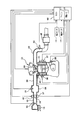
- FIG. 1 is a diagram showing a schematic configuration of an engine control system
- 2A is a diagram showing a full lift state of the fuel injection valve
- FIG. 2B is a diagram showing a partial lift state of the fuel injection valve
- FIG. 3 is a diagram showing a partial lift region and a full lift region
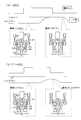
- FIG. 4 is a diagram showing injection pulses and valve lift behavior in partial lift injection
- FIG. 5 is a diagram showing injection pulses and valve lift behavior in full lift injection
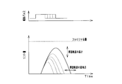
- 6A is a diagram showing lift behavior by partial lift injection for individual fuel injection valves A and B
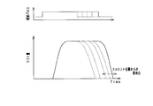
- FIG. 6B is a diagram showing lift behavior of full lift injection for individual fuel injection valves A and B.
- FIG. And FIG. 7 is a diagram showing the relationship between the energization time and the injection amount for the individual fuel injection valves A and B.
- FIG. 8 is a diagram for explaining the relationship between the valve lift behavior and the voltage behavior with respect to the energization time
- FIG. 9 is a functional block diagram showing injection amount correction processing in partial lift injection
- 10A is a diagram showing lift correlation data
- FIG. 10B is a diagram showing injection amount correlation data
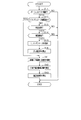
- FIG. 11 is a flowchart showing a processing procedure of fuel injection control.
- FIG. 12 is a functional block diagram showing injection amount correction processing in partial lift injection in the second embodiment.
- 13A is a diagram showing lift correlation data
- FIG. 13B is a diagram showing injection amount correlation data
- FIG. 14 is a flowchart showing a processing procedure of fuel injection control in the second embodiment.
- FIG. 15 is a functional block diagram showing injection amount correction processing in partial lift injection in the third embodiment.
- FIG. 16 is a diagram showing injection amount correlation data
- FIG. 17 is a flowchart showing a processing procedure of fuel injection control in the third embodiment.
- FIG. 18 is a functional block diagram showing injection amount correction processing in partial lift injection in the fourth embodiment.
- FIG. 19 is a diagram showing injection amount correlation data.
- FIG. 20 is a flowchart showing a processing procedure of fuel injection control in the fourth embodiment.
- FIG. 21 is a flowchart showing a processing procedure of fuel injection control in another example.
- This embodiment is embodied as a control system for controlling a gasoline engine for a vehicle.
- parts that are the same or equivalent to each other are given the same reference numerals in the drawings, and the description of the same reference numerals is used.
- An air cleaner 13 is provided at the most upstream portion of the intake pipe 12 of the engine 11 which is a cylinder injection type multi-cylinder internal combustion engine, and an air flow meter 14 for detecting the intake air amount is provided downstream of the air cleaner 13. ing.
- a throttle valve 16 whose opening is adjusted by a motor 15 and a throttle opening sensor 17 for detecting the opening (throttle opening) of the throttle valve 16 are provided on the downstream side of the air flow meter 14.
- a surge tank 18 is provided downstream of the throttle valve 16, and an intake pipe pressure sensor 19 for detecting the intake pipe pressure is provided in the surge tank 18.
- An intake manifold 20 that introduces air into each cylinder 21 of the engine 11 is connected to the surge tank 18.
- An electromagnetically driven fuel injection valve 30 that directly injects fuel into each cylinder is connected to each cylinder 21 of the engine 11. Is attached.
- An ignition plug 22 is attached to the cylinder head of the engine 11 for each cylinder 21, and the air-fuel mixture in the cylinder is ignited by spark discharge of the ignition plug 22 of each cylinder 21.
- the exhaust pipe 23 of the engine 11 is provided with an exhaust sensor 24 such as an air-fuel ratio sensor or an oxygen sensor that detects the air-fuel ratio or rich / lean of the air-fuel mixture based on the exhaust gas.
- a catalyst 25 such as a three-way catalyst for purifying exhaust gas is provided on the downstream side of the exhaust sensor 24.
- the cylinder block of the engine 11 is provided with a cooling water temperature sensor 26 that detects the cooling water temperature and a knock sensor 27 that detects knocking.
- a crank angle sensor 28 that outputs a pulse signal every time the crankshaft rotates a predetermined crank angle is attached to the outer peripheral side of the crankshaft. Based on the crank angle signal of the crank angle sensor 28, the crank angle and the engine rotation speed are determined. Detected. The outputs of these various sensors are sequentially input to the ECU 40.
- the ECU 40 is an electronic control unit mainly composed of a microcomputer, and performs various controls of the engine 11 based on detection signals from various sensors using a control program stored in a built-in ROM (storage medium). To do.
- the ECU 40 corresponds to a fuel injection control device.
- the ECU 40 calculates the fuel injection amount according to the engine operating state, controls the fuel injection of the fuel injection valve 30, and controls the ignition timing of the spark plug 22.
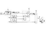
- the ECU 40 includes an engine control microcomputer 41 that performs the fuel injection control, and a drive IC 42 for driving the fuel injection valve.
- the microcomputer 41 calculates the required injection amount based on the engine operating state such as the engine rotation speed and the engine load, calculates the injection pulse width (energization time) based on the required injection amount, and calculates the injection pulse width.
- the driving IC 42 opens the fuel injection valve 30 with an injection pulse generated based on the injection pulse width, and injects fuel for the required injection amount.
- the fuel injection valve 30 is provided with a voltage sensor 43 that detects a negative terminal voltage and a current sensor 44 that detects an energization current flowing through an electromagnetic part (coil). The detection results of the voltage sensor 43 and the current sensor 44 are sequentially output to the ECU 40.
- the fuel injection valve 30 includes a coil 31 as an electromagnetic part that generates an electromagnetic force when energized, a fixed core 32 made of a magnetic material, and a fixed core 32 made of a magnetic material.
- the movable core 33 to be sucked, the needle-like valve body 34 that is driven integrally with the movable core 33, the first spring 35 that biases the valve body 34 toward the valve closing side, and the movable core 33 to be anti-closed And a second spring 36 biased to the side.
- the coil 31 is energized, the valve element 34 moves away from the valve seat and moves to the valve opening side, whereby the fuel injection valve 30 is opened and fuel injection is performed.
- the urging force of the second spring 36 is set smaller than the urging force of the first spring 35.
- the injection pulse width (energization time) is different, and when the injection pulse width is relatively long as shown in FIG. 2A, that is, the valve body lift amount becomes the full lift amount. In this case, the valve body 34 reaches the full lift position where the movable core 33 abuts against the stopper 32a on the fixed core 32 side.
- the injection pulse width becomes relatively short, that is, when the valve body lift amount becomes the partial lift amount, the valve body 34 is in front of the movable core 33 hitting the stopper 32a. This is a partial lift state that does not reach the full lift position.
- the movable core 33 and the valve body 34 return to the valve closing position, whereby the fuel injection valve 30 is closed, and the fuel injection is stopped.
- the valve body 34 is held in the closed position when the valve body 34 reaches the closed position, whereas the movable core 33 33 moves to the tip side more independently.
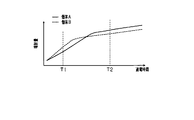
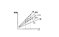
- FIG. 3 is a diagram showing a partial lift region in which partial lift injection is performed and a full lift region in which full lift injection is performed.
- the injection amount tends to increase as the energization time as the injection pulse width increases.
- the characteristics of the injection amount increase / decrease with respect to the energization time are different between the partial lift region and the full lift region, for example, the inclination of the increase in injection amount with respect to the energization time is different.
- the valve body 34 when performing partial lift injection, the valve body 34 does not reach the full lift position (fully open position), and the lift behavior of the valve body 34 forms a parabolic trajectory. At this time, as the energization time (injection pulse width) increases, the height of the trajectory, that is, the peak lift position in the intermediate lift state increases, and the landing point of the trajectory, that is, the valve element 34 is closed. Timing is delayed.
- valve body 34 when full lift injection is performed, the valve body 34 reaches the full lift position, and is temporarily held at the full lift position and then closed. At this time, as the energization time (injection pulse width) increases, the landing point from the full lift position, that is, the valve closing timing of the valve body 34 is delayed.
- the change characteristic of the actual injection amount with respect to the injection pulse width is deteriorated in the partial lift region, and there is a concern that the fuel injection amount varies among individuals. That is, in the partial lift region, the variation in lift behavior of the valve body 34 tends to increase and the variation in injection amount tends to increase. When the variation in injection amount increases, exhaust emission and drivability may deteriorate.
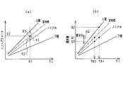
- FIG. 6A is a diagram showing the lift behavior of the valve body 34 when the partial lift injection is performed for the individual fuel injection valves 30 A and B
- FIG. It is a figure which shows the lift behavior of the valve body 34 at the time of implementation of full lift injection about the solid A and B.
- a lift operation is performed by partial lift injection and full lift injection as in lift behavior examples 1 and 2, respectively.
- the injection pulses for the individuals A and B are the same, and the energization time is, for example, T1 in FIG.
- the energization time is, for example, T1 in FIG.
- FIG. 7 is a diagram showing the relationship between the energization time and the injection amount for similar individuals A and B.
- the individual A and B When performing the partial lift injection, the individual A and B have different maximum lift amounts and valve closing timings at the peak lift positions in both the lift behavior example 1 and the lift behavior example 2, and the individual B In this case, the maximum lift amount is larger and the valve closing timing is later. Therefore, as shown in FIG. 7, in the injection amount characteristic in the partial lift region, the injection amount is individual A ⁇ individual B. As shown as lift behavior examples 1 and 2, the difference in lift behavior between individuals A and B occurs as variations in lift amount and valve closing timing.
- the causes include the spring force of springs 35 and 36 and coil energization. Variations in electromagnetic attraction force can be considered.
- the injection amount characteristic in the full lift region is individual A> individual B.
- the injection amount characteristics are different between the partial lift region and the full lift region.
- the injection amount is individual A ⁇ individual B, whereas in the full lift region, the injection amount is individual.
- the variation in the full lift position is considered to be caused by the variation in the position of the fixed core 32 in the fuel injection valve 30.
- the variation in the valve closing timing is caused by the variation in the linking force acting on the valve body 34 in the full lift state. That is, in the full lift state, a linking force (adhesive force) is generated on the contact surface of the valve body 34. Therefore, after the injection pulse is turned off, the valve body 34 moves to the valve closing side while being influenced by the linking force. For example, it is conceivable that the valve closing timing is delayed as the linking force increases.
- the linking force may vary depending on the properties of the fuel (for example, viscosity).
- the injection amount correction in the partial lift injection is performed while paying attention to the difference in the injection amount characteristics between the case where the partial lift injection is performed in the fuel injection valve 30 and the case where the full lift injection is performed.
- the ECU 40 acquires the actual lift behavior of the valve body 34 as an actual lift characteristic when partial lift injection is performed, and compares the actual lift characteristic with a predetermined reference characteristic as a nominal characteristic. Based on the result of the comparison, the fuel injection amount in the partial lift injection is corrected.
- a lift parameter corresponding to the lift behavior of the valve element 34 is acquired in association with the injection pulse width (energization time). Specifically, the valve closing timing of the valve body 34 after the injection pulse is turned off (after the energization is turned off) is detected as a lift parameter, and the actual lift characteristic is grasped from the lift parameter.
- the valve closing timing of the valve element 34 Since the detection method of the valve closing timing of the valve element 34 is already known, it will be briefly described here.
- the minus terminal voltage changes due to the induced electromotive force after the injection pulse is turned off.
- the negative terminal voltage changes due to a change in speed of the valve body 34 when the valve body 34 reaches the valve closing position, and a voltage inflection point occurs at the valve closing timing.
- the valve closing timing of the fuel injection valve 30 can be detected by observing the change of the negative terminal voltage by the voltage sensor 43.
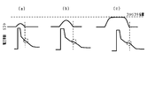
- FIGS. 8A and 8B are diagrams for explaining the relationship between the lift behavior of the valve element 34 and the behavior of the negative terminal voltage with respect to the energization time.
- FIGS. 8A and 8B are behaviors in partial lift injection, and FIG. The behavior in full lift injection is shown.
- the energization time is (a) ⁇ (b) (c).
- the voltage change is stably detected at the valve closing timing of the valve body 34, whereas in (a), the valve body lift amount is too small, and therefore the valve closing timing. It is difficult to detect the voltage change at. Therefore, in the present embodiment, the valve closing timing as the lift parameter is detected on the condition that it is a predetermined high flow rate region in the partial lift region.
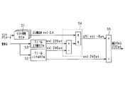
- FIG. 9 is a functional block diagram showing the injection amount correction process in the partial lift injection, and each function of this process is realized by the ECU 40.
- the configuration shown in FIG. 9 corresponds to a “fuel injection correction unit”.
- the injection amount correction in the partial lift injection is performed using the relationship shown in FIGS. 10 (a) and 10 (b).
- FIG. 10A is a diagram showing lift correlation data defining the relationship between the injection pulse width Ti and the lift parameter in the partial lift region
- FIG. 10B is a diagram showing the injection pulse width Ti and the fuel in the partial lift region. It is a figure which shows the injection quantity correlation data which prescribed
- 10A and 10B may be stored in a memory in the ECU 40 as map data, for example.
- 10A and 10B respectively define a nominal characteristic as a reference characteristic, an upper limit characteristic on the side where the lift parameter increases, and a lower limit characteristic on the side where the lift parameter decreases. Yes.
- the upper limit characteristic and the lower limit characteristic are limit characteristics that are an allowable upper limit and an allowable lower limit.
- These nominal characteristics, upper limit characteristics, and lower limit characteristics are model values determined by conformance, and may be determined including environmental differences such as individual differences and temperatures.
- the nominal characteristic, the upper limit characteristic, and the lower limit characteristic may be determined as having different gains (inclinations) of the lift parameter with respect to the injection pulse width Ti.
- the lift characteristic model unit 51 uses the relationship shown in FIG. 10 (a) to change the characteristic deviation with respect to the nominal characteristic based on the injection pulse width Ti (energization time) and the lift parameter in the current partial lift injection. calculate.
- the upper limit side deviation amount ratio with respect to the nominal characteristic is calculated based on the actual characteristic position between the nominal characteristic and the upper limit characteristic as the characteristic deviation.
- the lower limit side deviation amount ratio with respect to the nominal characteristic is calculated based on the actual characteristic position between the nominal characteristic and the lower limit characteristic.
- the lift characteristic model part 51 is good to have multiple lift correlation data of Fig.10 (a) according to a fuel pressure.
- the actual characteristic point is X3 when the injection pulse width Ti in the current partial lift injection is X1 and the lift parameter is X2.
- the actual lift characteristic is shifted to the upper limit side with respect to the nominal characteristic, and in the injection pulse width X1, the difference Y1 between the lift parameter at the upper limit characteristic and the lift parameter at the nominal characteristic, and the actual lift parameter
- the deviation amount ratio is calculated using the lower limit characteristic.
- the deviation ratio as the characteristic deviation may be normalized in the partial lift region.
- the deviation amount ratio may be calculated from a single-point lift parameter or a plurality of lift parameters.
- only one of the upper limit characteristic and the lower limit characteristic is defined in the lift correlation data, the process of calculating the upper limit side deviation amount ratio based on the upper limit characteristic, and the lower limit side deviation amount ratio based on the lower limit characteristic.
- the configuration may be such that only one of the calculation processing is performed.
- the Ti-Q upper / lower limit model unit 53 uses the upper limit characteristic or the lower limit characteristic in the injection amount correlation data of FIG. 10B, and corresponds to either the upper limit characteristic or the lower limit characteristic based on the required injection amount each time.
- the lift characteristic model unit 51 corresponds to a “deviation calculation unit”
- the Ti-Q nominal model unit 52, the Ti-Q upper / lower limit model unit 53, the correction width calculation unit 54, and the correction unit 55 are “correction”.
- the above pulse correction method using the nominal characteristics and the upper and lower limit characteristics is an example. If the injection pulse width can be corrected using the nominal characteristics and the upper and lower limit characteristics, intermediate variables and the like can be arbitrarily changed. Is possible.
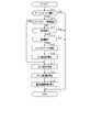
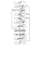
- FIG. 11 is a flowchart showing a processing procedure of fuel injection control, and this processing is performed by the ECU 40 at a predetermined cycle, for example.
- step S11 it is determined whether or not the current fuel injection is partial lift injection, and the process proceeds to subsequent step S12 on condition that the fuel injection is partial lift injection.
- step S12 it is determined whether or not the lift parameter has been acquired. If the lift parameter has not been acquired, the process proceeds to step S13. If the lift parameter has been acquired, the process proceeds to step S17. Note that step S12 may determine whether or not the deviation amount ratio has been calculated.
- step S13 it is determined whether or not the engine 11 is in a predetermined stable state. At this time, it is determined that the engine 11 is in a predetermined stable state based on, for example, that the engine speed and fuel pressure are stable (not in a transient state) and that the engine temperature is within a predetermined range. To do.
- step S14 it is determined whether or not the current partial lift injection is performed in a predetermined high flow rate region within the partial lift region. Specifically, it is determined whether or not the injection pulse width (energization time) is a predetermined value or more.
- the predetermined value may be a value that is 1/2, 2/3, or 3/4 of the maximum energization time set as the partial lift region, for example. If both step S13 and S14 are YES, it will progress to subsequent step S15, and if either of step S13 and S14 is NO, this process will be complete
- step S15 the lift parameter of the fuel injection valve 30 is acquired.
- the lift parameter is associated with the energization time of the current partial lift injection and is acquired as an actual lift characteristic.
- the valve closing timing may be detected based on the behavior of the negative terminal voltage after the injection pulse is turned off, and the valve closing timing may be acquired as a lift parameter.
- count of several injection may be sufficient. For example, an average value of a plurality of valve closing timings is used as the lift parameter.
- the structure which acquires several lift parameters according to the temperature conditions of the fuel injection valve 30 or the engine 11, for example may be sufficient.
- step S16 as the characteristic deviation of the actual lift characteristic, the upper limit side deviation amount ratio with respect to the nominal characteristic or the lower limit side deviation amount ratio with respect to the nominal characteristic is calculated, and the deviation amount ratio is stored in the memory.
- step S18 the pulse correction width ⁇ Ti is calculated by multiplying the pulse difference by the deviation amount ratio.
- step S19 the corrected energization time (injection pulse width TA3) is calculated from the nominal pulse width TA1 and the pulse correction width ⁇ Ti.
- step S12 is YES and the process proceeds from step S12 to step S17, the deviation amount ratio is read from the memory in step S18, and the pulse correction width ⁇ Ti is calculated using the deviation amount ratio. . Therefore, when partial lift injection is performed in a region where the flow rate is lower than a predetermined high flow rate region, based on the deviation amount ratio (actual lift characteristic) acquired when performing partial lift injection in the high flow rate region. The injection amount correction is performed.
- the already acquired deviation amount ratio (actual lift) can be obtained even when partial lift injection is performed at a higher flow rate than the injection amount when the deviation amount ratio (actual lift characteristic) is acquired.
- the injection amount correction can be performed based on the characteristics.
- step S15 when the lift parameter is acquired, the lift parameter is stored in the memory (step S15), and in step S18, the pulse correction width ⁇ Ti is calculated using the lift parameter read from the memory. It may be.
- the full lift injection is different from the partial lift injection.
- the injection amount characteristics are different. That is, in each of these injections, the factors that cause the deviation of the injection amount characteristic are different. Focusing on this point, in the above configuration, when partial lift injection is performed, the actual lift behavior of the valve body 34 is acquired as an actual lift characteristic, and the actual lift characteristic and a predetermined reference characteristic (nominal characteristic) And the correction of the fuel injection amount in the partial lift injection is performed based on the result of the comparison.
- the injection amount correction is also performed at the time of performing the partial lift injection.
- correction of partial lift injection can be appropriately performed while avoiding a decrease in accuracy due to different injection amount characteristics between full lift injection and partial lift injection.
- the partial lift injection can be performed with high accuracy in the fuel injection valve 30.
- partial lift injection fine injection with a short injection pulse width (that is, energization time) is performed.
- the injection pulse width is shorter, the lift amount of the valve element 34 becomes smaller, and accordingly, it becomes difficult to obtain the actual lift characteristics.
- the actual lift characteristics are obtained, and the actual lift characteristics are used to correct the partial lift injection injection amount.
- the injection amount correction can be appropriately performed.
- the lift parameter when the lift parameter is acquired based on the behavior of the minus terminal voltage of the fuel injection valve 30 or the behavior of the coil energization current, if the injection pulse width is too short, the behavior of the minus terminal voltage or the behavior of the coil energization current will be reduced. There is a concern that it will not be possible to observe properly and the lift parameters will not be properly acquired. In this respect, since the lift parameter is acquired on the condition that the partial lift injection is performed in the high flow rate region within the partial lift region, the lift parameter can be appropriately acquired.
- the injection amount is based on the deviation amount ratio calculated when partial lift injection is performed in the high flow rate region. A correction was made. As a result, in the low flow rate region in the partial lift region, even if the lift parameter in the low flow rate region is not acquired, appropriate injection amount correction can be performed. That is, it is possible to avoid using a low-precision lift parameter and perform an appropriate injection amount correction using a high-precision lift parameter acquired in a high flow rate region.
- the characteristic deviation (displacement amount) with respect to the nominal characteristics based on the energization time and lift parameter in the current partial lift injection
- the ratio is calculated, and the injection amount correction is performed based on the characteristic deviation.
- the deviation amount ratio with respect to the nominal characteristic is calculated.
- the deviation amount ratio instead of the absolute amount of deviation. Correction can be performed. That is, it is possible to appropriately correct the injection amount using the deviation amount ratio even in a region other than the injection amount for which the lift parameter is actually acquired.
- the pulse correction width ⁇ Ti (energization time deviation for the nominal characteristics in the injection amount correlation data is used.
- the injection amount is corrected by correcting the injection pulse width Ti on the basis of the pulse correction width ⁇ Ti. In this case, the injection amount correction can be appropriately performed based on the nominal characteristic in the injection amount correlation data.
- the injection amount correlation data defining the relationship between the energization time and the injection amount in the partial lift region is used, and the injection amount deviation width with respect to the nominal characteristic in the injection amount correlation data is based on the characteristic deviation of the fuel injection valve 30. And the energization time is corrected based on the injection amount deviation width.
- FIG. 12 is a functional block diagram showing injection amount correction processing in partial lift injection, and each function of this processing is realized by the ECU 40.
- injection amount correction in partial lift injection is performed using the relationship shown in FIGS.
- FIG. 13 (a) is a diagram showing lift correlation data as in FIG. 10 (a)
- FIG. 13 (b) shows injection quantity correlation data as in FIG. 10 (b).
- FIG. 13A and 13B define a nominal characteristic, an upper limit characteristic, and a lower limit characteristic, respectively.
- the lift characteristic model unit 61 uses the relationship shown in FIG. 13A, and calculates the characteristic deviation from the nominal characteristic based on the injection pulse width Ti (energization time) and the lift parameter in the current partial lift injection. calculate.
- the lift characteristic model unit 61 has the same configuration as the lift characteristic model unit 51 of FIG. 9 described above.
- the injection pulse width Ti in the current partial lift injection is X1 and the lift parameter is X2
- the actual characteristic point is obtained as X3.
- the Ti-Q upper / lower limit model unit 62 uses the upper limit characteristic or the lower limit characteristic shown in FIG. 13 (b), and based on the injection pulse width on the nominal characteristic corresponding to the required injection amount each time, the upper limit characteristic or A limit injection amount corresponding to one of the lower limit characteristics is calculated.
- the required injection amount is Q1
- the injection pulse width on the nominal characteristic according to the required injection amount Q1 is TB1
- the upper limit injection amount on the upper limit characteristic according to the injection pulse width TB1 is Q2. Yes.
- the injection pulse width TB2 is the corrected injection pulse width, and the injection amount control of the partial lift injection is performed based on the injection pulse width TB2.
- the lift characteristic model unit 61 corresponds to a “deviation calculation unit”
- the Ti-Q upper / lower limit model unit 62, the correction width calculation unit 63, and the correction unit 64 correspond to a “correction execution unit”.
- FIG. 14 is a flowchart showing a processing procedure of fuel injection control, and this processing is performed by the ECU 40 at a predetermined cycle, for example. This process is performed in place of the process of FIG. 11 described above. In FIG. 14, the same processing as that in FIG. 11 is given the same step number and its description is omitted.
- steps S11 to S16 are the same processing as FIG. 11, and the deviation amount ratio is calculated based on the lift parameter when performing partial lift injection by steps S11 to S16.
- step S21 an injection amount difference which is a difference between the required injection amount Q1 and the limit injection amount Q2 (upper limit injection amount or lower limit injection amount) is calculated.
- step S22 the injection amount correction width ⁇ Q is calculated by multiplying the injection amount difference by the deviation amount ratio.
- step S23 a corrected required amount Q3 is calculated from the required injection amount Q1 and the injection amount correction width ⁇ Q.
- step S24 the injection pulse width corresponding to the corrected required amount Q3 on the nominal characteristic is calculated as the corrected energization time (injection pulse width TB2).
- the injection amount correction can be appropriately performed based on the nominal characteristic in the injection amount correlation data.
- the energization time deviation width with respect to the nominal characteristics at a plurality of injection amounts based on the characteristic deviation of the fuel injection valve 30 is updated by updating the injection amount correlation data based on the plurality of energization time deviation widths.
- the injection amount correlation data is updated over the entire region of the partial lift region. For this reason, a plurality of injection amounts may be determined over a wide range (for example, the entire region) in the partial lift region.
- FIG. 15 is a functional block diagram showing the characteristic update process in the partial lift injection, and each function of this process is realized by the ECU 40.
- the lift characteristic model unit 71 uses the above-described lift correlation data in FIG. 10A, and based on the actual lift parameters acquired at the time of performing partial lift injection, the characteristic deviation (deviation amount ratio) with respect to the nominal characteristic. ) Is calculated.
- the lift characteristic model unit 71 has the same configuration as the lift characteristic model unit 51 of FIG. 9 described above.
- the Ti-Q nominal model unit 72 stores nominal characteristics in the injection amount correlation data
- the Ti-Q upper / lower limit model unit 73 also stores upper limit characteristics and lower limit characteristics in the injection amount correlation data. (See FIG. 16).
- the correction width calculation unit 74 calculates the difference between the nominal characteristic and the upper limit characteristic or the lower limit characteristic at a plurality of injection amounts over the entire injection amount in the partial lift region as the upper limit side time difference or the lower limit side time difference, and the time difference Based on the deviation amount ratio, a plurality of pulse correction widths ⁇ Ti (energization time deviation widths) are calculated over the entire injection amount in the partial lift region.
- the characteristic updating unit 75 adds the pulse correction width ⁇ Ti at a plurality of injection amounts to the injection pulse width Ti on the nominal characteristics over the entire injection amount in the partial lift region, so that the nominal characteristic of the injection amount correlation data is obtained. Update. In this case, for example, the injection amount correlation data that is map data is updated (rewritten).
- the lift characteristic model unit 71 corresponds to a “deviation calculation unit”
- the Ti-Q nominal model unit 72, the Ti-Q upper / lower limit model unit 73, the correction width calculation unit 74, and the characteristic update unit 75 are “ It corresponds to “Correction Execution Unit”.
- FIG. 17 is a flowchart showing a processing procedure of fuel injection control, and this processing is performed by the ECU 40 at a predetermined cycle, for example. This process is performed in place of the process shown in FIG. In FIG. 17, the same processing as that in FIG. 11 is given the same step number and the description thereof is omitted.
- steps S11 to S16 are the same processing as FIG. 11, and the deviation amount ratio is calculated based on the lift parameters when performing the partial lift injection by steps S11 to S16.
- step S31 the difference in energization time between the nominal characteristic and the upper limit characteristic or the lower limit characteristic is calculated as an upper limit side time difference or a lower limit side time difference at a plurality of injection amounts over the entire injection amount in the partial lift region.
- step S32 the pulse correction width ⁇ Ti is calculated over the entire injection amount in the partial lift region based on the time difference and the deviation amount ratio.
- step S33 the nominal characteristic is updated with the pulse correction width ⁇ Ti for a plurality of injection amounts over the entire injection amount in the partial lift region. Thereby, the corrected characteristic is calculated.
- the injection amount correlation data used in the partial lift region can be updated based on the deviation amount ratio calculated at the time of performing the partial lift injection, and an appropriate fuel injection amount can be obtained by updating the data.
- Control can be implemented. Further, for example, by updating (rewriting) the map data, correction processing is performed collectively in a wide injection range, and the calculation load can be reduced with respect to the correction calculation.
- the injection amount correlation data that defines the relationship between the energization time and the injection amount in the partial lift region
- the injection amount correction is performed by correcting the injection amount correlation data based on the plurality of injection amount deviation widths.
- the injection amount correlation data is updated over the entire region of the partial lift region. For this reason, a plurality of injection amounts may be determined over a wide range (for example, the entire region) in the partial lift region.
- FIG. 18 is a functional block diagram showing the characteristic update process in the partial lift injection, and each function of this process is realized by the ECU 40.
- the lift characteristic model unit 81 uses the above-described lift correlation data in FIG. 10A, and based on the actual lift parameters acquired at the time of performing partial lift injection, the characteristic deviation (deviation amount ratio) with respect to the nominal characteristic. ) Is calculated.
- the lift characteristic model unit 81 has the same configuration as the lift characteristic model unit 51 of FIG. 9 described above.
- the Ti-Q nominal model unit 82 stores nominal characteristics in the injection amount correlation data
- the Ti-Q upper / lower limit model unit 83 similarly stores upper limit characteristics and lower limit characteristics in the injection amount correlation data. (See FIG. 19).
- the correction width calculation unit 84 calculates the difference between the nominal characteristic and the upper limit characteristic or the lower limit characteristic as the upper limit side flow rate difference or the lower limit side flow rate difference at a plurality of energization times in the entire energization time of the partial lift region.
- a plurality of injection amount correction widths ⁇ Q injection amount deviation widths are calculated over the entire energization time in the partial lift region based on the flow rate difference and the deviation amount ratio.
- the characteristic updating unit 85 adds the injection amount correction width ⁇ Q for a plurality of energization times (injection pulse widths) to the injection amount on the nominal characteristic over the entire injection amount in the partial lift region, thereby correcting the injection amount correlation. Update the nominal characteristics of the data. In this case, for example, the injection amount correlation data that is map data is updated (rewritten).
- the lift characteristic model unit 81 corresponds to a “deviation calculation unit”
- the Ti-Q nominal model unit 82, the Ti-Q upper / lower limit value model unit 83, the correction width calculation unit 84, and the characteristic update unit 85 are “ It corresponds to “Correction Execution Unit”.
- the update process will be described more specifically with reference to FIG.
- a case where the actual lift characteristic is shifted to the upper limit side with respect to the nominal characteristic is illustrated.
- FIG. 19 for a plurality of energization times (injection pulse widths), an upper limit side flow rate difference ⁇ Qx between the nominal characteristic and the upper limit characteristic is calculated, and an injection amount correction width ⁇ Q is calculated.
- the nominal characteristic is updated by adding the injection amount correction width ⁇ Q for each energization time. Thereby, a corrected characteristic in accordance with the actual lift characteristic is obtained.
- FIG. 20 is a flowchart showing a processing procedure of fuel injection control, and this processing is performed by the ECU 40 at a predetermined cycle, for example. This process is performed in place of the process shown in FIG. In FIG. 20, the same processes as those in FIG. 11 are given the same step numbers and the description thereof is omitted.
- steps S11 to S16 are the same processing as in FIG. 11, and the deviation amount ratio is calculated based on the lift parameter when performing the partial lift injection by steps S11 to S16.
- step S41 the difference in the injection amount between the nominal characteristic and the upper limit characteristic or the lower limit characteristic is calculated as an upper limit side flow rate difference or a lower limit side flow rate difference over a plurality of energization times throughout the energization time of the partial lift region.
- step S42 the injection amount correction width ⁇ Q is calculated over the entire energization time of the partial lift region based on the flow rate difference and the deviation amount ratio.
- step S43 the nominal characteristic is updated with the injection amount correction width ⁇ Q for a plurality of energization times throughout the energization time in the partial lift region. Thereby, the corrected characteristic is calculated.
- the injection amount correlation data used in the partial lift region can be updated based on the deviation amount ratio calculated at the time of performing the partial lift injection, and an appropriate fuel injection amount can be obtained by updating the data.
- Control can be implemented. Further, for example, by updating (rewriting) the map data, correction processing is performed collectively in a wide injection range, and the calculation load can be reduced with respect to the correction calculation.
- valve body 34 When the valve body 34 unintentionally reaches the full lift position when performing the partial lift injection, a linking force is generated in the valve body 34, so that a desired partial lift injection characteristic may not be obtained. For example, when partial lift injection is performed in a high flow rate region within the partial lift region, it is considered that the valve body 34 may reach the full lift position unexpectedly.
- the ECU 40 determines that the valve body 34 has reached the full lift position after the energization of the fuel injection valve 30 is started when the partial lift injection is performed. And when it determines with the valve body having reached 34 full lift positions, either acquisition of an actual lift characteristic and injection quantity correction
- the ECU 40 performs the process of FIG. 21 in which a part of the process of FIG. 11 is changed, for example.
- the ECU 40 proceeds to step S51 after acquiring the lift parameter of the fuel injection valve 30 when the partial lift injection is performed in the high flow rate region within the partial lift region.
- step S51 it is determined whether or not the valve element 34 has reached the full lift position during the current valve element lift. At this time, for example, it may be determined that the valve element 34 has reached the full lift position based on a change in the coil energization current. That is, the behavior of the valve body that accompanies the valve body 34 reaching the full lift position is determined by the coil energization current.
- the fuel injection valve 30 is configured to detect that the valve body 34 has reached the full lift position by a contact-type sensor provided at the full lift position of the valve body 34, a lift sensor that detects the valve body lift amount, or the like. May be.
- step S51 is NO, it will progress to subsequent step S16, and if step S51 is YES, this process will be complete
- step S51 is YES, that is, when the valve body 34 reaches the full lift position, the lift parameter acquired this time is invalidated.
- valve closing timing of the valve body 34 is acquired as a lift parameter, but this may be changed.
- the structure which acquires the valve opening timing of the valve body 34, and the valve opening period from valve opening to valve closing as a lift parameter may be sufficient.
- the lift behavior of the valve body 34 in the fuel injection valve 30 may be detected by, for example, a lift sensor, and the detection result may be acquired as an actual lift characteristic.
- the actual lift characteristics (lift parameters such as valve closing timing) may be acquired at the time, and the injection amount correction in the partial lift injection may be performed based on the actual lift characteristics. For example, when the actual lift characteristic in the partial lift injection is not acquired, the ECU 40 performs the injection amount correction in the partial lift injection based on the actual lift characteristic in the full lift injection.
- ⁇ Can be applied to diesel engines in addition to gasoline engines. That is, it is good also as a structure which implements partial lift injection control as mentioned above about the fuel injection valve for diesel engines.
Landscapes
- Engineering & Computer Science (AREA)
- Chemical & Material Sciences (AREA)
- Combustion & Propulsion (AREA)
- Mechanical Engineering (AREA)
- General Engineering & Computer Science (AREA)
- Electrical Control Of Air Or Fuel Supplied To Internal-Combustion Engine (AREA)
- Fuel-Injection Apparatus (AREA)
- Combined Controls Of Internal Combustion Engines (AREA)
- Magnetically Actuated Valves (AREA)
Priority Applications (2)
| Application Number | Priority Date | Filing Date | Title |
|---|---|---|---|
| DE112018002791.0T DE112018002791B4 (de) | 2017-05-30 | 2018-05-29 | Kraftstoffeinspritzsteuerungsvorrichtung für Verbrennungskraftmaschine |
| US16/693,745 US11365700B2 (en) | 2017-05-30 | 2019-11-25 | Fuel injection control device for internal combustion engine |
Applications Claiming Priority (2)
| Application Number | Priority Date | Filing Date | Title |
|---|---|---|---|
| JP2017-107027 | 2017-05-30 | ||
| JP2017107027A JP6705427B2 (ja) | 2017-05-30 | 2017-05-30 | 内燃機関の燃料噴射制御装置 |
Related Child Applications (1)
| Application Number | Title | Priority Date | Filing Date |
|---|---|---|---|
| US16/693,745 Continuation US11365700B2 (en) | 2017-05-30 | 2019-11-25 | Fuel injection control device for internal combustion engine |
Publications (1)
| Publication Number | Publication Date |
|---|---|
| WO2018221527A1 true WO2018221527A1 (ja) | 2018-12-06 |
Family
ID=64456205
Family Applications (1)
| Application Number | Title | Priority Date | Filing Date |
|---|---|---|---|
| PCT/JP2018/020593 Ceased WO2018221527A1 (ja) | 2017-05-30 | 2018-05-29 | 内燃機関の燃料噴射制御装置 |
Country Status (4)
| Country | Link |
|---|---|
| US (1) | US11365700B2 (enExample) |
| JP (1) | JP6705427B2 (enExample) |
| DE (1) | DE112018002791B4 (enExample) |
| WO (1) | WO2018221527A1 (enExample) |
Families Citing this family (3)
| Publication number | Priority date | Publication date | Assignee | Title |
|---|---|---|---|---|
| JP7283418B2 (ja) * | 2020-02-25 | 2023-05-30 | 株式会社デンソー | 内燃機関の燃料噴射制御装置 |
| JP7412606B2 (ja) * | 2021-01-12 | 2024-01-12 | 日立Astemo株式会社 | 燃料噴射制御装置 |
| DE102022205308A1 (de) * | 2022-05-27 | 2023-11-30 | Hitachi Astemo, Ltd. | Steuerungsvorrichtung und Verfahren zur Steuerung eines lnjektors |
Citations (3)
| Publication number | Priority date | Publication date | Assignee | Title |
|---|---|---|---|---|
| JP2015096720A (ja) * | 2013-10-11 | 2015-05-21 | 株式会社デンソー | 内燃機関の燃料噴射制御装置 |
| JP2015121231A (ja) * | 2015-04-01 | 2015-07-02 | 日立オートモティブシステムズ株式会社 | 内燃機関の制御装置 |
| JP2017061882A (ja) * | 2015-09-24 | 2017-03-30 | 株式会社デンソー | 内燃機関の燃料噴射制御装置 |
Family Cites Families (8)
| Publication number | Priority date | Publication date | Assignee | Title |
|---|---|---|---|---|
| JP5754357B2 (ja) * | 2011-11-18 | 2015-07-29 | 株式会社デンソー | 内燃機関の燃料噴射制御装置 |
| JP5727395B2 (ja) | 2012-01-16 | 2015-06-03 | 日立オートモティブシステムズ株式会社 | 内燃機関の制御装置 |
| JP6156307B2 (ja) * | 2013-10-11 | 2017-07-05 | 株式会社デンソー | 内燃機関の燃料噴射制御装置 |
| JP6233080B2 (ja) * | 2014-02-10 | 2017-11-22 | 株式会社デンソー | 燃料噴射制御装置 |
| JP6307971B2 (ja) * | 2014-03-27 | 2018-04-11 | 株式会社デンソー | 燃料噴射制御装置 |
| JP6206329B2 (ja) * | 2014-05-30 | 2017-10-04 | 株式会社デンソー | 内燃機関の燃料噴射制御装置 |
| JP6164244B2 (ja) * | 2015-04-23 | 2017-07-19 | トヨタ自動車株式会社 | 内燃機関の燃料噴射制御装置 |
| US10012168B2 (en) | 2015-06-11 | 2018-07-03 | Toyota Jidosha Kabushiki Kaisha | Control system |
-
2017
- 2017-05-30 JP JP2017107027A patent/JP6705427B2/ja active Active
-
2018
- 2018-05-29 DE DE112018002791.0T patent/DE112018002791B4/de active Active
- 2018-05-29 WO PCT/JP2018/020593 patent/WO2018221527A1/ja not_active Ceased
-
2019
- 2019-11-25 US US16/693,745 patent/US11365700B2/en active Active
Patent Citations (3)
| Publication number | Priority date | Publication date | Assignee | Title |
|---|---|---|---|---|
| JP2015096720A (ja) * | 2013-10-11 | 2015-05-21 | 株式会社デンソー | 内燃機関の燃料噴射制御装置 |
| JP2015121231A (ja) * | 2015-04-01 | 2015-07-02 | 日立オートモティブシステムズ株式会社 | 内燃機関の制御装置 |
| JP2017061882A (ja) * | 2015-09-24 | 2017-03-30 | 株式会社デンソー | 内燃機関の燃料噴射制御装置 |
Also Published As
| Publication number | Publication date |
|---|---|
| DE112018002791B4 (de) | 2024-09-26 |
| JP2018204444A (ja) | 2018-12-27 |
| DE112018002791T5 (de) | 2020-04-02 |
| US11365700B2 (en) | 2022-06-21 |
| JP6705427B2 (ja) | 2020-06-03 |
| US20200088124A1 (en) | 2020-03-19 |
Similar Documents
| Publication | Publication Date | Title |
|---|---|---|
| JP6292070B2 (ja) | 燃料噴射制御装置 | |
| JP6307971B2 (ja) | 燃料噴射制御装置 | |
| CN103946522B (zh) | 内燃机的燃料喷射控制设备 | |
| JP6156307B2 (ja) | 内燃機関の燃料噴射制御装置 | |
| JP6477321B2 (ja) | 内燃機関の燃料噴射制御装置 | |
| US10260448B2 (en) | Fuel injection control device for internal combustion engine | |
| US10428755B2 (en) | Control device for internal combustion engine | |
| WO2015052915A1 (ja) | 内燃機関の燃料噴射制御装置 | |
| JP6358163B2 (ja) | 内燃機関の燃料噴射制御装置 | |
| JP6304156B2 (ja) | 内燃機関の燃料噴射制御装置 | |
| WO2018221527A1 (ja) | 内燃機関の燃料噴射制御装置 | |
| JP6981366B2 (ja) | 燃料噴射弁の制御装置およびその方法 | |
| US11060474B2 (en) | Fuel injection control device | |
| JP7006155B2 (ja) | 燃料噴射制御装置 | |
| JP6035583B2 (ja) | 内燃機関の燃料噴射制御装置 | |
| JP7000720B2 (ja) | 内燃機関の燃料噴射制御装置 | |
| JP7035759B2 (ja) | 燃料噴射弁の制御装置およびその方法 |
Legal Events
| Date | Code | Title | Description |
|---|---|---|---|
| 121 | Ep: the epo has been informed by wipo that ep was designated in this application |
Ref document number: 18810832 Country of ref document: EP Kind code of ref document: A1 |
|
| 122 | Ep: pct application non-entry in european phase |
Ref document number: 18810832 Country of ref document: EP Kind code of ref document: A1 |