WO2018221127A1 - リアクトル - Google Patents
リアクトル Download PDFInfo
- Publication number
- WO2018221127A1 WO2018221127A1 PCT/JP2018/017762 JP2018017762W WO2018221127A1 WO 2018221127 A1 WO2018221127 A1 WO 2018221127A1 JP 2018017762 W JP2018017762 W JP 2018017762W WO 2018221127 A1 WO2018221127 A1 WO 2018221127A1
- Authority
- WO
- WIPO (PCT)
- Prior art keywords
- winding
- terminal block
- resin
- reactor
- terminal
- Prior art date
- Legal status (The legal status is an assumption and is not a legal conclusion. Google has not performed a legal analysis and makes no representation as to the accuracy of the status listed.)
- Ceased
Links
Images





Classifications
-
- H—ELECTRICITY
- H01—ELECTRIC ELEMENTS
- H01F—MAGNETS; INDUCTANCES; TRANSFORMERS; SELECTION OF MATERIALS FOR THEIR MAGNETIC PROPERTIES
- H01F27/00—Details of transformers or inductances, in general
- H01F27/28—Coils; Windings; Conductive connections
- H01F27/29—Terminals; Tapping arrangements for signal inductances
- H01F27/292—Surface mounted devices
-
- H—ELECTRICITY
- H01—ELECTRIC ELEMENTS
- H01F—MAGNETS; INDUCTANCES; TRANSFORMERS; SELECTION OF MATERIALS FOR THEIR MAGNETIC PROPERTIES
- H01F27/00—Details of transformers or inductances, in general
- H01F27/28—Coils; Windings; Conductive connections
- H01F27/29—Terminals; Tapping arrangements for signal inductances
-
- H—ELECTRICITY
- H01—ELECTRIC ELEMENTS
- H01F—MAGNETS; INDUCTANCES; TRANSFORMERS; SELECTION OF MATERIALS FOR THEIR MAGNETIC PROPERTIES
- H01F27/00—Details of transformers or inductances, in general
- H01F27/06—Mounting, supporting or suspending transformers, reactors or choke coils not being of the signal type
-
- H—ELECTRICITY
- H01—ELECTRIC ELEMENTS
- H01F—MAGNETS; INDUCTANCES; TRANSFORMERS; SELECTION OF MATERIALS FOR THEIR MAGNETIC PROPERTIES
- H01F27/00—Details of transformers or inductances, in general
- H01F27/24—Magnetic cores
- H01F27/26—Fastening parts of the core together; Fastening or mounting the core on casing or support
- H01F27/263—Fastening parts of the core together
-
- H—ELECTRICITY
- H01—ELECTRIC ELEMENTS
- H01F—MAGNETS; INDUCTANCES; TRANSFORMERS; SELECTION OF MATERIALS FOR THEIR MAGNETIC PROPERTIES
- H01F27/00—Details of transformers or inductances, in general
- H01F27/24—Magnetic cores
- H01F27/26—Fastening parts of the core together; Fastening or mounting the core on casing or support
- H01F27/266—Fastening or mounting the core on casing or support
-
- H—ELECTRICITY
- H01—ELECTRIC ELEMENTS
- H01F—MAGNETS; INDUCTANCES; TRANSFORMERS; SELECTION OF MATERIALS FOR THEIR MAGNETIC PROPERTIES
- H01F27/00—Details of transformers or inductances, in general
- H01F27/28—Coils; Windings; Conductive connections
- H01F27/2823—Wires
- H01F27/2828—Construction of conductive connections, of leads
-
- H—ELECTRICITY
- H01—ELECTRIC ELEMENTS
- H01F—MAGNETS; INDUCTANCES; TRANSFORMERS; SELECTION OF MATERIALS FOR THEIR MAGNETIC PROPERTIES
- H01F27/00—Details of transformers or inductances, in general
- H01F27/28—Coils; Windings; Conductive connections
- H01F27/30—Fastening or clamping coils, windings, or parts thereof together; Fastening or mounting coils or windings on core, casing, or other support
- H01F27/306—Fastening or mounting coils or windings on core, casing or other support
-
- H—ELECTRICITY
- H01—ELECTRIC ELEMENTS
- H01F—MAGNETS; INDUCTANCES; TRANSFORMERS; SELECTION OF MATERIALS FOR THEIR MAGNETIC PROPERTIES
- H01F27/00—Details of transformers or inductances, in general
- H01F27/28—Coils; Windings; Conductive connections
- H01F27/32—Insulating of coils, windings, or parts thereof
- H01F27/327—Encapsulating or impregnating
-
- H—ELECTRICITY
- H01—ELECTRIC ELEMENTS
- H01F—MAGNETS; INDUCTANCES; TRANSFORMERS; SELECTION OF MATERIALS FOR THEIR MAGNETIC PROPERTIES
- H01F27/00—Details of transformers or inductances, in general
- H01F27/40—Structural association with built-in electric component, e.g. fuse
- H01F27/402—Association of measuring or protective means
-
- H—ELECTRICITY
- H01—ELECTRIC ELEMENTS
- H01F—MAGNETS; INDUCTANCES; TRANSFORMERS; SELECTION OF MATERIALS FOR THEIR MAGNETIC PROPERTIES
- H01F37/00—Fixed inductances not covered by group H01F17/00
-
- H—ELECTRICITY
- H01—ELECTRIC ELEMENTS
- H01F—MAGNETS; INDUCTANCES; TRANSFORMERS; SELECTION OF MATERIALS FOR THEIR MAGNETIC PROPERTIES
- H01F27/00—Details of transformers or inductances, in general
- H01F27/40—Structural association with built-in electric component, e.g. fuse
- H01F27/402—Association of measuring or protective means
- H01F2027/406—Temperature sensor or protection
Definitions
- the present invention relates to a reactor.
- This application claims priority based on Japanese Patent Application No. 2017-105287, filed on May 29, 2017, and incorporates all the contents described in the aforementioned Japanese application.
- Patent Documents 1 to 3 include a coil having a winding portion formed by winding a winding, an inner core portion arranged inside the winding portion, and an outer core portion arranged outside the winding portion.
- An annular magnetic core having a reactor is disclosed. Normally, power is supplied to the coil from an external device such as a power supply via external wiring (such as a lead wire or a bus bar).
- a reactor is installed and used for installation objects, such as a converter case, for example.
- Patent Document 1 the outer periphery of a combined body of a coil and a magnetic core is covered with an outer resin portion, and a terminal fitting connected to the end of the winding is formed integrally with the outer resin portion above the outer core portion.
- the terminal block is provided with a nut for fastening the terminal fitting and the terminal of the external wiring with a bolt or the like.
- Patent Documents 2 to 3 describe that a fixing portion for fixing to an installation target with a bolt is formed in the outer resin portion covering the outer core portion (see paragraphs [0047] and Patent Document 2). (See paragraph [0070] of Patent Document 3 and FIG. 1).
- the reactor according to the present disclosure is A coil having a winding portion formed by winding a winding; and a magnetic core having an inner core portion arranged inside the winding portion and an outer core portion arranged outside the winding portion.
- a reactor An outer resin portion covering at least the outer surface of the outer core portion;
- a terminal block having a fastening portion that projects from the outer surface of the outer resin portion and is integrally formed, and that fastens a terminal fitting connected to an end of the winding and a terminal of an external wiring;
- a fixed portion that is integrally formed with the terminal block and fixes the reactor to an installation target;
- the terminal block and the fixed part are integrated, and the thickness of the terminal block is thinner than the fixed part.
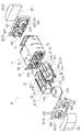
- FIG. 1 is a schematic perspective view of a reactor according to a first embodiment.
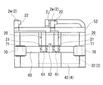
- 1 is a schematic top view of a reactor according to a first embodiment. It is a schematic exploded perspective view of the union body with which the reactor which concerns on Embodiment 1 is equipped.
- FIG. 4 is a schematic cross-sectional view taken along line (IV)-(IV) shown in FIG.
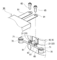
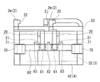
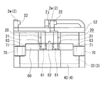
- FIG. 2 is a schematic cross-sectional view taken along line (V)-(V) shown in FIG. 1 is a schematic side view of a reactor according to a first embodiment. It is a figure explaining the fastening method of the terminal metal fitting in the reactor which concerns on Embodiment 1, and the terminal of external wiring.
- FIG. 10 is an enlarged perspective view of a main part showing a wiring locking part in a reactor according to Modification 2.
- the present disclosure provides a reactor that can further reduce the height of the reactor including the terminal block.
- the reactor of the present disclosure can further reduce the height of the reactor including the terminal block.
- the inventors have integrally formed the terminal block so as to protrude from the outer surface of the outer resin portion that covers the outer core portion (the side opposite to the side on which the inner core portion is disposed).
- the connection between the coil and the external wiring is made by fastening the terminal fitting connected to the end of the winding and the terminal of the external wiring to the nut of the terminal block with a bolt or the like. Tightening force acts on the terminal block. If the terminal block protrudes and is molded integrally with the outer surface of the outer resin part, the terminal block may be broken or cracked by the bolt tightening force, so make the terminal block thicker to withstand the bolt tightening force. There is a need. However, if the terminal block is made thick, there is a possibility that it is not possible to secure a space for arranging components arranged in the vicinity of the terminal block. Therefore, it is desired to reduce the thickness of the terminal block while ensuring the strength of the terminal block.
- the present inventors project the terminal block and the fixed portion on the outer surface of the outer resin portion and integrally form the terminal block and the fixed portion so that the terminal block can be made thin. It was found that the strength of the terminal block can be secured. First, embodiments of the present invention will be listed and described.
- a reactor according to an aspect of the present invention is A coil having a winding portion formed by winding a winding; and a magnetic core having an inner core portion arranged inside the winding portion and an outer core portion arranged outside the winding portion.
- a reactor An outer resin portion covering at least the outer surface of the outer core portion;
- a terminal block having a fastening portion that projects from the outer surface of the outer resin portion and is integrally formed, and that fastens a terminal fitting connected to an end of the winding and a terminal of an external wiring;
- a fixed portion that is integrally formed with the terminal block and fixes the reactor to an installation target;
- the terminal block and the fixed part are integrated, and the thickness of the terminal block is thinner than the fixed part.
- the terminal block protrudes and is integrally formed on the outer surface of the outer resin portion that covers the outer core portion, compared to the conventional reactor in which the terminal block is integrally formed above the outer core portion, The height of the reactor including the terminal block can be further reduced.
- the fixed part for fixing the reactor to the installation target is integrally formed with the terminal block, and the terminal block and the fixed part are integrated, thereby improving the strength of the terminal block and the strength of the terminal block. Can be secured. Therefore, it can suppress that a terminal block is damaged when fastening a terminal metal fitting and the terminal of external wiring, making thickness of a terminal block thin. Further, since the thickness of the terminal block is thinner than that of the fixed portion, it is easy to secure an arrangement space for components arranged in the vicinity of the terminal block.
- the terminal block is formed integrally with the outer resin part, there is no need to attach a separately prepared terminal block, the number of parts can be reduced, assembly work can be simplified, and manufacturing costs can be reduced. it can.
- the fastening portion is a nut to which a bolt is fastened, and the nut is embedded in the terminal block.
- the fastening part can be easily configured, and the nut does not fall off from the terminal block. Since the terminal fitting and the terminal of the external wiring can be fastened with bolts, the coil and the external wiring can be easily connected.
- the fixing part may be fixed to the installation target with a metal bolt or the like.
- the object to be installed is a ground potential, and a potential difference is generated between the terminal fitting provided on the terminal block and the bolt.
- the wall part ensures a sufficient creepage distance between the terminal fitting and the bolt and enhances electrical insulation between them. Can do.
- a sensor that measures the physical quantity of the reactor is provided, and a wiring locking portion that locks the wiring of the sensor is formed on the terminal block.
- the wiring of the sensor can be fixed to the wiring locking portion by forming the wiring locking portion on the terminal block. Therefore, for example, when the reactor is installed on the installation target, it is less likely that the sensor wiring is caught or the wiring becomes an obstacle.
- the reactor 1 according to the first embodiment includes a combination 10 of a coil 2 having a winding part 2c and a magnetic core 3 arranged inside and outside the winding part 2c.
- the coil 2 has two winding portions 2c, and both winding portions 2c are arranged side by side.
- the magnetic core 3 includes two inner core portions 31 disposed on the inner side of the winding portion 2c and two outer cores disposed on the outer side of the winding portion 2c and connecting the ends of the inner core portions 31 to each other. Part 32.
- the reactor 1 is provided with the outer side resin part 42 (mold resin part 4) which covers at least the outer surface 32o of the outer core part 32, as shown in FIG. 1, FIG.
- the reactor 1 is provided with the outer side resin part 42 (mold resin part 4) which covers at least the outer surface 32o of the outer core part 32, as shown in FIG. 1, FIG.
- the terminal block 60 and the fixed portion 70 protrude from the outer surface of the outer resin portion 42 and are integrally formed (see also FIG. 6).
- the reactor 1 (combined body 10) includes an insulating interposed member 5 interposed between the coil 2 and the magnetic core 3 as shown in FIG.
- the reactor 1 is installed on an installation target (not shown) such as a converter case, for example.
- the lower side in FIG. 1 and FIG. 6 is the installation side facing the installation target, the installation side is “down”, and the opposite side is “up”.
- the vertical direction is the height direction.
- the direction in which the winding portions 2c (inner core portion 31) are arranged is the horizontal direction, and the direction along the axial direction of the winding portion 2c (inner core portion 31) (the paper surface in FIG. 2).
- the vertical direction is the length direction.
- FIG. 4 is a cross-sectional view cut in a transverse direction perpendicular to the length direction of the winding portion 2c
- FIG. 5 is a plan cross-sectional view cut along a plane that divides the winding portion 2c up and down.
- the coil 2 has two winding portions 2c each formed by spirally winding two windings 2w, and each winding forming both winding portions 2c.
- One ends of the line 2w are connected to each other through the joint 2j.
- Both winding portions 2c are arranged side by side (in parallel) so that their axial directions are parallel to each other.
- the joining portion 2j is formed by joining one end portions of the winding 2w drawn from each winding portion 2c by a joining method such as welding, soldering, or brazing.
- the other end portions of the windings 2w are each drawn out from each winding portion 2c in an appropriate direction (upward in this example).
- a terminal fitting 20 see FIG. 1; not shown in FIG.
- each winding 2w that is, both ends of the coil 2). They are electrically connected via external wiring 90 (see FIG. 7).
- the coil 2 can use a well-known thing, for example, the both winding parts 2c may be formed by one continuous winding.
- Both winding portions 2c are composed of the windings 2w having the same specifications, have the same shape, size, winding direction, and number of turns, and adjacent turns forming the winding portion 2c are in close contact with each other.
- the winding 2w is, for example, a coated wire (so-called enameled wire) having a conductor (copper or the like) and an insulating coating (polyamideimide or the like) on the outer periphery of the conductor.
- each winding part 2c is a square cylindrical (specifically, rectangular cylindrical) edgewise coil obtained by edgewise winding a winding 2w of a covered rectangular wire, and the winding part 2c viewed from the axial direction.
- the end face shape is a rectangular shape with rounded corners (see also FIG. 4).
- the shape of the winding part 2c is not particularly limited, and may be, for example, a cylindrical shape, an elliptical cylindrical shape, a long cylindrical shape (race track shape), or the like.
- the specifications of the winding 2w and the winding part 2c can be changed as appropriate.
- the coil 2 (the winding part 2c) is not covered with a mold resin part 4 to be described later, and when the reactor 1 is configured, the outer peripheral surface of the coil 2 is exposed as shown in FIG. become. Therefore, heat can be easily radiated from the coil 2 to the outside, and the heat dissipation of the coil 2 can be enhanced.
- the coil 2 may be a molded coil molded with a resin having electrical insulation.
- the coil 2 can be protected from the external environment (such as dust and corrosion), and the mechanical strength and electrical insulation of the coil 2 can be increased.
- the electrical insulation between the winding part 2c and the inner core part 31 can be improved because the inner peripheral surface of the winding part 2c is covered with resin.
- the resin for molding the coil 2 include thermosetting resins such as epoxy resins, unsaturated polyester resins, urethane resins, and silicone resins, polyphenylene sulfide (PPS) resins, polytetrafluoroethylene (PTFE) resins, and liquid crystal polymers.
- Thermoplastic resins such as (LCP), polyamide (PA) resin such as nylon 6 and nylon 66, polyimide (PI) resin, polybutylene terephthalate (PBT) resin, acrylonitrile butadiene styrene (ABS) resin, and the like can be used.
- LCP polyamide
- PA polyamide
- PI polyimide
- PBT polybutylene terephthalate
- ABS acrylonitrile butadiene styrene
- the coil 2 may be a heat fusion coil in which a fusion layer is provided between adjacent turns forming the winding portion 2c, and the adjacent turns are thermally fused. In this case, adjacent turns can be brought into closer contact with each other.
- the magnetic core 3 includes two inner core portions 31 disposed inside the winding portion 2c and two outer cores disposed outside the winding portion 2c.
- the inner core portion 31 is a portion where the coil 2 is disposed, positioned inside the winding portions 2c arranged side by side. That is, both the inner core parts 31 are arrange
- the inner core portion 31 may have a part of the end portion in the axial direction protruding from the winding portion 2c.
- the outer core part 32 is a part which is located outside the winding part 2c and where the coil 2 is not substantially disposed (that is, protrudes (exposes) from the winding part 2c).
- the outer core portion 32 is provided so as to connect the end portions of the inner core portions 31 to each other.
- the outer core portions 32 are arranged so as to sandwich the inner core portion 31 from both ends, and the end surfaces of both inner core portions 31 are connected to the inner side surface 32i of the outer core portion 32 so as to face each other.
- An annular magnetic core 3 is configured. In the magnetic core 3, when the coil 2 is energized and excited, a magnetic flux flows and a closed magnetic path is formed.
- the shape of the inner core portion 31 is a shape corresponding to the inner peripheral surface of the winding portion 2c.
- the inner core portion 31 is formed in a quadrangular prism shape (rectangular column shape), and the end surface shape of the inner core portion 31 viewed from the axial direction is a rectangular shape with chamfered corner portions (see also FIG. 4).
- the outer peripheral surface of the inner core portion 31 has four planes (upper surface, lower surface, and two side surfaces) and four corners.
- the inner core part 31 has the some inner core piece 31m, and the inner core piece 31m is comprised in the length direction, and is comprised. .
- the inner core portion 31 is formed of a material containing a soft magnetic material.
- the inner core piece 31m is formed by compression molding, for example, soft magnetic powder such as iron or an iron alloy (Fe-Si alloy, Fe-Si-Al alloy, Fe-Ni alloy, etc.) or a coated soft magnetic powder having an insulating coating. It is formed of a powder compact or a composite material compact including soft magnetic powder and resin.
- a thermosetting resin, a thermoplastic resin, a room temperature curable resin, a low temperature curable resin, or the like can be used.
- the thermosetting resin include unsaturated polyester resin, epoxy resin, urethane resin, and silicone resin.
- thermoplastic resin examples include PPS resin, PTFE resin, LCP, PA resin, PI resin, PBT resin, and ABS resin.
- BMC Bulk molding compound in which calcium carbonate or glass fiber is mixed with unsaturated polyester, millable silicone rubber, millable urethane rubber, or the like can also be used.
- the inner core piece 31m is formed of a green compact.
- the outer core portion 32 is a columnar body having a trapezoidal upper surface, and is composed of one core piece.
- the outer core portion 32 is formed of a material containing a soft magnetic material, similarly to the inner core piece 31m, and the above-described compacted molded body, molded body of composite material, and the like can be used.
- the outer core portion 32 is formed of a green compact.
- the insulating interposition member 5 is interposed between the coil 2 (winding portion 2 c) and the magnetic core 3 (inner core portion 31 and outer core portion 32), and provides electrical insulation between the coil 2 and the magnetic core 3.
- This is a member to be secured, and has an inner interposed member 51 and an end surface interposed member 52.
- the insulating interposing member 5 (the inner interposing member 51 and the end surface interposing member 52) is formed of an electrically insulating resin, such as an epoxy resin, an unsaturated polyester resin, a urethane resin, a silicone resin, a PPS resin, a PTFE resin, or an LCP. , PA resin, PI resin, PBT resin, ABS resin and the like.
- the inner interposed member 51 is interposed between the inner peripheral surface of the winding portion 2 c and the outer peripheral surface of the inner core portion 31, and is formed between the winding portion 2 c and the inner core portion 31. Ensure electrical insulation between.
- the inner interposed member 51 is formed at the rectangular plate portion 510 interposed between the inner core pieces 31 m and the corner portion of the plate portion 510, and adjacent to each other. And a projecting piece 511 extending in the length direction along the corner of the inner core piece 31m.
- a frame portion 512 is formed on the outer edge portion of the plate portion 510 so as to surround the peripheral edge portions of the end surfaces of the adjacent inner core pieces 31m.
- the plate portion 510 functions as a gap while maintaining an interval between the inner core pieces 31m.
- the projecting piece 511 holds the corner portion of the inner core piece 31m and is interposed between the inner peripheral surface of the winding portion 2c and the outer peripheral surface of the inner core piece 31m, so that the inner core piece is placed in the winding portion 2c.
- Position 31m inner core portion 31.
- a gap is formed between the inner peripheral surface of the winding portion 2 c and the outer peripheral surface of the inner core portion 31 by the protrusion 511, and the four surfaces (upper surface, lower surface, and both side surfaces) of the inner core portion 31 are formed. ) Is secured in each case.
- Each gap serves as a resin flow path that forms an inner resin portion 41 (see FIGS. 4 and 5), which will be described later, and the inner resin portion 41 is formed by filling each gap with resin. Further, as shown in FIG. 3, the protruding pieces 511 of the adjacent inner interposed members 51 are butted together and connected.
- the end surface interposed member 52 is interposed between the end surface of the winding part 2 c and the inner side surface 32 i of the outer core part 32, and between the winding part 2 c and the outer core part 32. Ensure electrical insulation.
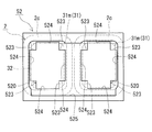
- the end surface interposed members 52 are respectively arranged at both ends of the winding part 2c, and are rectangular frame bodies in which two through holes 520 into which the inner core part 31 is inserted are formed as shown in FIG. In this example, as shown in FIG. 8, when the end surface interposed member 52 is viewed from the outer core portion 32 side (front side), the end surface interposed member 52 is in contact with the corner portion of the end surface of the inner core portion 31 (inner core piece 31m).
- a protrusion 523 that protrudes inward of the through hole 520 is formed. As shown in FIG. 5, the protrusion 523 is interposed between the corner of the end surface of the inner core portion 31 and the inner side surface 32 i of the outer core portion 32, and as shown in FIG. A gap is formed between 32i and 32i. Further, as shown in FIG. 8, each through hole 520 is formed in a cross shape, and in the state of the combined body 10, the through hole 520 includes an inner peripheral surface of the winding portion 2 c and an outer periphery of the inner core portion 31. Resin filling holes 524 communicating with the gaps between the surfaces are formed. Via this resin filling hole 524, it is possible to fill the gaps between the winding part 2c and the inner core part 31 with resin.
- a concave fitting portion 525 is formed to which the inner side surface 32i side of the outer core portion 32 is fitted.
- the outer core portion 32 is positioned with respect to the end surface interposed member 52 by the fitting portion 525.
- the end surface interposed member 52 extends in the length direction along the corner portion of the inner core piece 31 m located at the end portion of the inner core portion 31 on the inner core portion 31 side (rear surface side).
- a protruding piece 521 is formed.
- the projecting piece 521 holds the corner portion of the inner core piece 31m located at the end of the inner core portion 31, and is interposed between the inner peripheral surface of the winding portion 2c and the outer peripheral surface of the inner core piece 31m.
- the inner core piece 31m (inner core portion 31) is positioned in the winding portion 2c.
- the inner core portion 31 is positioned with respect to the end surface interposed member 52 by the projecting piece 521, and as a result, the inner core portion 31 and the outer core portion 32 can be positioned via the end surface interposed member 52.
- the protruding piece 521 of the end surface interposed member 52 is abutted against and connected to the protruding piece 511 of the inner interposed member 51.
- the gap between the inner peripheral surface of the winding portion 2 c and the outer peripheral surface of the inner core portion 31 is caused by the protruding pieces 511 and 521 over the length direction of the inner core portion 31. It is divided in the circumferential direction.
- the outer resin portion 42 is formed so as to cover at least the outer surface 32 o of the outer core portion 32 (surface opposite to the inner surface 32 i on which the inner core portion 31 is disposed). ing.
- the outer resin part 42 is formed so as to cover the entire outer peripheral surface of the outer core part 32 exposed to the outside when the assembled body 10 is assembled, and not only the outer face 32o but also the outer core part 32 The upper surface and the lower surface are also covered with the outer resin portion 42.
- the outer resin portion 42 is formed by coating the outer core portion 32 with resin by injection molding.
- the outer resin portion 42 is formed of a resin having electrical insulation.
- a thermosetting resin such as epoxy resin, unsaturated polyester resin, urethane resin, and silicone resin
- thermoplastic resins such as PPS resin, PTFE resin, LCP, PA resin, PI resin, PBT resin, and ABS resin
- PPS resin PTFE resin
- LCP unsaturated polyester resin
- PA resin PA resin
- PI resin PI resin
- PBT resin polystyrene resin
- ABS resin polystyrene resin
- an inner resin portion 41 filled between the inner peripheral surface of the winding portion 2 c and the outer peripheral surface of the inner core portion 31 is provided.
- the inner resin portion 41 is formed by filling a resin between the winding portion 2c and the inner core portion 31 by injection molding.
- the inner peripheral surface of the winding portion 2c and the outer peripheral surface of the inner core portion 31 are formed. It is in close contact with.
- the inner resin portion 41 and the outer resin portion 42 are integrally formed, and the inner resin portion 41 and the outer resin portion 42 constitute the mold resin portion 4.
- the inner core portion 31 and the outer core portion 32 are integrated by the mold resin portion 4, and the coil 2, the magnetic core 3, and the insulating interposed member 5 constituting the combined body 10 are integrated.
- the gap between the end surface of the inner core portion 31 and the inner side surface 32 i of the outer core portion 32 is also filled with resin.
- the terminal block 60 protrudes from the outer surface of the outer resin portion 42 and is integrally formed.
- the terminal block 60 has terminals 91 (see FIG. 7) of the terminal fitting 20 and the external wiring 90.
- a fastening portion (nut 61) that fastens the joint.
- two fastening portions are provided on the terminal block 60 so as to correspond to the terminal fittings 20 respectively connected to the end portions of the windings 2w (see also FIGS. 6 and 7).
- the terminal block 60 is provided on the outer resin portion 42 that covers one outer core portion 32 where the end of the winding 2w is located.
- the nut 61 is embedded in the terminal block 60, so that a fastening portion is configured.
- the nut 61 has a screw hole in which an internal thread is formed on the inner periphery, and a bolt 65 (see FIG. 7) is fastened.
- a square nut having a polygonal outer shape or a round nut having a circular outer shape can be used. In this example, a hexagonal nut is used (see FIGS. 2 and 5).
- the nut 61 is a so-called cap nut, and as shown in FIG. 6, the bottom on the side opposite to the side into which the bolt 65 is inserted is closed. In FIG. 6, the cross section of the nut 61 is hatched for easy understanding.
- FIG. 6 shows a case where the nut 61 is a cap nut, the nut 61 may be a through nut through which a screw hole passes.
- the terminal fitting 20 is a rod-shaped conductor, and is connected to the end of the winding 2w and wired between the end of the winding 2w and the fastening portion (nut 61), as shown in FIGS. ing.
- the terminal fitting 20 is disposed on a nut 61 embedded in the terminal block 60, and is connected to a terminal portion 21 that is fastened to a terminal 91 (see FIG. 7) of the external wiring 90 and an end portion of the winding 2w. Part 22.
- the terminal portion 21 is formed in an annular plate shape and has a through hole through which the bolt 65 is inserted.
- connection portion 22 is formed in a U shape so as to sandwich the end portion of the winding 2w, and is connected to the end portion of the winding 2w by a joining method such as welding, soldering, or brazing.
- a terminal 91 is provided at a terminal, and a through hole through which the bolt 65 is inserted is formed in the terminal 91.
- the fastening of the terminal fitting 20 and the terminal 91 of the external wiring 90 is performed by superimposing the terminal 91 of the external wiring 90 on the terminal portion 21 of the terminal fitting 20 arranged on the nut 61. This is done by inserting the bolt 65 into the nut 61 and tightening the bolt.
- a commercially available metal can be used for the nut 61 and the bolt 65.
- a partition 62 formed of an outer resin portion 42 is provided on the terminal block 60 so as to separate the terminal fittings 20.
- the creeping distance between the terminal fittings 20 can be lengthened, and the electrical strength between the terminal fittings 20 can be increased. What is necessary is just to set the height of the partition part 62 suitably so that a required creepage distance can be ensured according to the voltage applied to the coil 2, a use environment, etc.
- the fixing portion 70 is for fixing the reactor 1 to an installation target (not shown), and is integrally formed with the terminal block 60 as shown in FIGS. 1 and 2.
- a metal collar 71 (cylindrical body) is embedded in the fixing portion 70, and a through hole through which a bolt used for the fixing tool is inserted is formed.
- the reactor 1 is fixed to the installation target by inserting a bolt (not shown) into the collar 71 of the fixing unit 70 and fastening it to a bolt hole provided in the installation target.
- Commercially available metal can be used for the collar 71 and the bolt used for the fixture.
- the fixing portion 70 is provided on the outer resin portion 42 that covers both the outer core portions 32, and two fixing portions 70 are provided on each outer resin portion 42. Yes.
- the fixing portion 70 is disposed on each of the left and right sides of the outer resin portion 42, and a terminal block 60 is provided so as to be bridged between the fixing portions 70.
- the number and position of the fixing portions 70 can be changed as appropriate, and may be one for each outer resin portion 42.
- the terminal block 60 and the fixing portion 70 integrally protrude from the outer surface of the outer resin portion 42 to form one protruding portion, and the thickness of the terminal block 60 is as follows. It is thinner than the fixed part 70.
- the terminal block 60 and the fixing portion 70 are provided at an intermediate position in the height direction of the outer resin portion 42.
- the positions where the terminal block 60 and the fixing portion 70 are provided can be changed as appropriate, and may be the lower side or the upper side of the outer resin portion 42 in the height direction.
- a rib (not shown) may be formed on the lower side of the terminal block 60. In this case, the rigidity of the fixing portion 70 can be increased by the rib.
- the reactor 1 may be provided with the sensor 8 which measures a physical quantity, as shown in FIG.
- the sensor 8 shown in FIG. 1 includes a wiring 81 that is held by a sensor holder 80 and transmits sensing information (electrical signal) of the sensor 8 to a control device (not shown).
- the sensor 8 can be appropriately selected according to the physical quantity to be measured.
- the sensor 8 is a thermistor that measures the temperature of the coil 2, and is attached so that the sensor holder 80 is inserted between the winding portions 2c and the sensor 8 is disposed on the upper side between the winding portions 2c. .
- ⁇ Reactor manufacturing method> An example of a method for manufacturing the reactor 1 will be described.
- the method for manufacturing a reactor is roughly divided into an assembly assembly process and a resin molding process.
- the combination assembly process In the combination assembly process, the combination 10 of the coil 2, the magnetic core 3, and the insulating interposed member 5 is assembled (see FIG. 3).
- the inner interposition member 51 is disposed between the inner core pieces 31m to produce the inner core portion 31, and the inner core portions 31 are inserted into both winding portions 2c of the coil 2, respectively.
- the end face interposed members 52 are respectively disposed at both ends of the winding portion 2c, and the outer core portions 32 are respectively disposed so as to sandwich the inner core portion 31 from both ends.
- the inner core portion 31 and the outer core portion 32 constitute an annular magnetic core 3 (see FIG. 2).
- the combined body 10 including the coil 2, the magnetic core 3, and the insulating interposed member 5 is assembled.
- the resin molding step resin is injection molded to the outer core portion 32 to form the outer resin portion 42, and the terminal block 60 and the fixing portion 70 are integrally molded to the outer resin portion 42 (see FIGS. 1 and 5).
- the combined body 10 is set in a molding die (not shown), and components such as a nut 61 and a collar 71 are arranged in a space for forming the terminal block 60 and the fixing portion 70 in the molding die.
- resin is inject
- the resin is filled in the gap between the winding portion 2c and the inner core portion 31 via the resin filling hole 524 (see FIG. 8) of the end surface interposed member 52, and the end surface of the inner core portion 31 and the outer core portion 32 are filled.
- the resin is also filled in the gap between the inner side surface 32i of the resin.
- the outer resin portion 42 is formed by solidifying the resin, and at the same time, the terminal block 60 in which the nut 61 is embedded and the fixing portion 70 in which the collar 71 is embedded are integrally formed in the outer resin portion 42.
- the inner side resin part 41 is formed simultaneously with the outer side resin part 42, and the outer side resin part 42 and the inner side resin part 41 are integrally molded. Accordingly, the outer resin portion 42 and the inner resin portion 41 constitute the mold resin portion 4, the inner core portion 31 and the outer core portion 32 are integrated, and the coil 2, the magnetic core 3 and the insulating interposed member 5 are integrated. Turn into.
- the resin may be filled by filling the gap between the winding portion 2c and the inner core portion 31 from the one outer core portion 32 side toward the other outer core portion 32 side, or both outer core portions.
- the gap may be filled from the 32 side.
- the reactor 1 of Embodiment 1 has the following effects. Since the terminal block 60 protrudes and is integrally formed on the outer surface of the outer resin portion 42 covering the outer core portion 32, the height of the reactor 1 including the terminal block 60 can be further reduced. Further, since the terminal block 60 is integrally formed with the outer resin portion 42, it is not necessary to attach a separately prepared terminal block, and the number of parts can be reduced and the assembling work can be simplified.
- the terminal block 60 and the fixing portion 70 are integrally formed on the outer resin portion 42 and are connected to each other so that the strength of the terminal block 60 is improved. Therefore, since the strength of the terminal block 60 can be secured while the thickness of the terminal block 60 can be reduced, the terminal block 60 can be prevented from being damaged when the terminal fitting 20 and the terminal 91 of the external wiring 90 are bolted. . Since the thickness of the terminal block 60 is thinner than the fixed portion 70, it is easy to secure an arrangement space for components arranged in the vicinity of the terminal block 60.
- the fastening part can be easily configured by embedding the nut 61 in the terminal block 60. Since the terminal fitting 20 and the terminal 91 of the external wiring 90 can be fastened with bolts, the coil 2 and the external wiring 90 can be easily connected. Further, since the bottom of the nut 61 is closed, the wear powder (metal powder) generated by the friction between the bolt 65 and the nut 61 does not fall out of the nut 61 when the bolt is tightened. Therefore, troubles such as a short circuit due to wear powder can be avoided, and reliability can be improved.
- a wall 63 may be formed by the outer resin portion 42 between the terminal block 60 and the fixing portion 70.
- the upper surfaces of the terminal block 60 and the fixing portion 70 are substantially the same height, and the wall portion 63 is formed so as to protrude from the upper surface.
- fixed part 70 differs, and the wall part 63 is formed of the level
- the wall portion 63 between the terminal block 60 and the fixing portion 70, the creepage distance between the terminal fitting 20 and the bolt inserted into the fixing portion 70 (collar 71) by the wall portion 63. It is possible to increase the electrical insulation between the two by increasing the length. What is necessary is just to set the height of the wall part 63 suitably so that a required creepage distance can be ensured according to the voltage applied to the coil 2, a use environment, etc.
- a wiring locking portion 64 that locks the wiring 81 of the sensor 8 may be formed on the terminal block 60.
- the wiring latching portion 64 shown in FIG. 11 is integrally formed with the terminal block 60, and is a tongue-like projecting piece extending upward from the partitioning portion 62, and an attachment hole 640 is formed on the tip side thereof. Then, the wiring 81 is locked to the wiring locking portion 64 by binding the wiring 81 by passing the binding band 641 through the mounting hole 640. Since the wiring locking portion 64 is provided on the terminal block 60, the wiring 81 of the sensor 8 can be fixed to the wiring locking portion 64. For example, when the reactor 1 is installed on the installation target, the wiring 81 is connected. It is less likely to get caught or get in the way of the wiring 81.
Landscapes
- Engineering & Computer Science (AREA)
- Power Engineering (AREA)
- Coils Of Transformers For General Uses (AREA)
Abstract
巻線を巻回してなる巻回部を有するコイルと、前記巻回部の内側に配置される内側コア部及び前記巻回部の外側に配置される外側コア部を有する磁性コアと、を備えるリアクトルであって、前記外側コア部の少なくとも外側面を覆う外側樹脂部と、前記外側樹脂部の外側面に突出して一体成形され、前記巻線の端部に接続される端子金具と外部配線の端子とを締結する締結部を有する端子台と、前記端子台に一体成形され、前記リアクトルを設置対象に固定する固定部と、を備え、前記端子台と前記固定部とが一体化され、前記端子台の厚さが前記固定部よりも薄いリアクトル。
Description
本発明は、リアクトルに関する。
本出願は、2017年5月29日付の日本国出願の特願2017-105287に基づく優先権を主張し、前記日本国出願に記載された全ての記載内容を援用するものである。
本出願は、2017年5月29日付の日本国出願の特願2017-105287に基づく優先権を主張し、前記日本国出願に記載された全ての記載内容を援用するものである。
電圧の昇圧動作や降圧動作を行う回路の部品の一つに、リアクトルがある。例えば特許文献1~3には、巻線を巻回してなる巻回部を有するコイルと、巻回部の内側に配置される内側コア部及び巻回部の外側に配置される外側コア部を有する環状の磁性コアと、を備えるリアクトルが開示されている。通常、コイルには、電源などの外部機器から外部配線(リード線やバスバーなど)を介して電力が供給される。また、リアクトルは、例えば、コンバータケースなどの設置対象に設置して使用される。
特許文献1には、コイルと磁性コアとの組合体の外周を外側樹脂部で覆い、外側コア部の上方に、巻線の端部に接続される端子金具を外側樹脂部で一体に成形して端子台を構成することが記載されている(特許文献1の段落[0026]、[0028]及び図2などを参照)。上記端子台には、端子金具と外部配線の端子とをボルトなどで締結するためのナットが設けられている。一方、特許文献2~3には、外側コア部を覆う外側樹脂部に、ボルトで設置対象に固定するための固定部を形成することが記載されている(特許文献2の段落[0047]及び図1など、特許文献3の段落[0070]及び図1などを参照)。
本開示に係るリアクトルは、
巻線を巻回してなる巻回部を有するコイルと、前記巻回部の内側に配置される内側コア部及び前記巻回部の外側に配置される外側コア部を有する磁性コアと、を備えるリアクトルであって、
前記外側コア部の少なくとも外側面を覆う外側樹脂部と、
前記外側樹脂部の外側面に突出して一体成形され、前記巻線の端部に接続される端子金具と外部配線の端子とを締結する締結部を有する端子台と、
前記端子台に一体成形され、前記リアクトルを設置対象に固定する固定部と、を備え、
前記端子台と前記固定部とが一体化され、前記端子台の厚さが前記固定部よりも薄い。
巻線を巻回してなる巻回部を有するコイルと、前記巻回部の内側に配置される内側コア部及び前記巻回部の外側に配置される外側コア部を有する磁性コアと、を備えるリアクトルであって、
前記外側コア部の少なくとも外側面を覆う外側樹脂部と、
前記外側樹脂部の外側面に突出して一体成形され、前記巻線の端部に接続される端子金具と外部配線の端子とを締結する締結部を有する端子台と、
前記端子台に一体成形され、前記リアクトルを設置対象に固定する固定部と、を備え、
前記端子台と前記固定部とが一体化され、前記端子台の厚さが前記固定部よりも薄い。
[本開示が解決しようとする課題]
近年、コンバータの小型化が進み、ケースの薄型化によってリアクトルの高さが制限されたり、コンバータに使用するリアクトルなどの部品の配置密度が高くなる傾向がある。特許文献1に記載のリアクトルでは、外側コア部の上方に外側樹脂部で端子台を一体成形しているが、設置スペースの関係上、外側コア部の上方に端子台を設けることが難しい場合がある。
近年、コンバータの小型化が進み、ケースの薄型化によってリアクトルの高さが制限されたり、コンバータに使用するリアクトルなどの部品の配置密度が高くなる傾向がある。特許文献1に記載のリアクトルでは、外側コア部の上方に外側樹脂部で端子台を一体成形しているが、設置スペースの関係上、外側コア部の上方に端子台を設けることが難しい場合がある。
そこで、本開示は、端子台を含むリアクトルの高さをより低減できるリアクトル提供する。
[本開示の効果]
本開示のリアクトルは、端子台を含むリアクトルの高さをより低減できる。
本開示のリアクトルは、端子台を含むリアクトルの高さをより低減できる。
[本発明の実施形態の説明]
本発明者らは、外側コア部を覆う外側樹脂部の外側面(内側コア部が配置される側とは反対側)から突出するように端子台を一体成形することで、外側コア部の上方に端子台を形成する場合に比較して、リアクトルの高さを低減することを考えた。しかし、この場合は、次のような問題が生じることが分かった。
本発明者らは、外側コア部を覆う外側樹脂部の外側面(内側コア部が配置される側とは反対側)から突出するように端子台を一体成形することで、外側コア部の上方に端子台を形成する場合に比較して、リアクトルの高さを低減することを考えた。しかし、この場合は、次のような問題が生じることが分かった。
通常、コイルと外部配線との接続は、巻線の端部に接続される端子金具と外部配線の端子とをボルトなどで端子台のナットに締結することにより行われるが、その際、ボルトの締め付け力が端子台に作用する。外側樹脂部の外側面に端子台を突出して一体成形した場合、ボルトの締め付け力によって端子台が折れたり、割れたりすることがあるため、ボルトの締め付け力に耐えられるように端子台を厚くする必要がある。しかしながら、端子台を厚くすると、端子台の近傍に配置される部品の配置スペースを確保できなくなる虞がある。したがって、端子台の強度を確保しつつ、端子台の厚さを薄くすることが望まれる。
本発明者らは、外側樹脂部の外側面に端子台と固定部とを突出して一体成形し、端子台と固定部とが連続するように一体化することで、端子台を薄くできつつ、端子台の強度を確保できることを見出した。最初に、本発明の実施態様を列記して説明する。
[本発明の実施形態の説明]
(1)本発明の一態様に係るリアクトルは、
巻線を巻回してなる巻回部を有するコイルと、前記巻回部の内側に配置される内側コア部及び前記巻回部の外側に配置される外側コア部を有する磁性コアと、を備えるリアクトルであって、
前記外側コア部の少なくとも外側面を覆う外側樹脂部と、
前記外側樹脂部の外側面に突出して一体成形され、前記巻線の端部に接続される端子金具と外部配線の端子とを締結する締結部を有する端子台と、
前記端子台に一体成形され、前記リアクトルを設置対象に固定する固定部と、を備え、
前記端子台と前記固定部とが一体化され、前記端子台の厚さが前記固定部よりも薄い。
(1)本発明の一態様に係るリアクトルは、
巻線を巻回してなる巻回部を有するコイルと、前記巻回部の内側に配置される内側コア部及び前記巻回部の外側に配置される外側コア部を有する磁性コアと、を備えるリアクトルであって、
前記外側コア部の少なくとも外側面を覆う外側樹脂部と、
前記外側樹脂部の外側面に突出して一体成形され、前記巻線の端部に接続される端子金具と外部配線の端子とを締結する締結部を有する端子台と、
前記端子台に一体成形され、前記リアクトルを設置対象に固定する固定部と、を備え、
前記端子台と前記固定部とが一体化され、前記端子台の厚さが前記固定部よりも薄い。
上記リアクトルは、外側コア部を覆う外側樹脂部の外側面に端子台が突出して一体成形されていることから、外側コア部の上方に端子台が一体成形された従来のリアクトルに比較して、端子台を含むリアクトルの高さをより低減できる。上記リアクトルによれば、リアクトルを設置対象に固定する固定部が端子台に一体成形され、端子台と固定部とが一体化されていることで、端子台の強度が向上し、端子台の強度を確保できる。よって、端子台の厚さを薄くできながら、端子金具と外部配線の端子とを締結する際に端子台が破損することを抑制できる。また、端子台の厚さが固定部よりも薄いことで、端子台の近傍に配置される部品の配置スペースを確保し易い。
上記リアクトルでは、外側樹脂部に端子台が一体成形されていることから、別途用意した端子台を取り付ける必要がなく、部品点数の削減、組立作業の簡素化を図ることができ、製造コストを低減できる。
(2)上記リアクトルの一形態として、前記締結部はボルトが締結されるナットであり、前記端子台に前記ナットが埋設されていることが挙げられる。
端子台にナットが埋設されていることで、締結部を容易に構成でき、ナットが端子台から脱落することもない。端子金具と外部配線の端子とをボルト締めで締結することができるので、コイルと外部配線との接続を容易に行うことができる。
(3)上記(2)に記載のリアクトルの一形態として、前記ナットは前記ボルトを挿入する側とは反対側の底が閉塞されていることが挙げられる。
ナットの底が閉塞されていることで、ボルト締めする際にボルトとナットとの摩擦によって生じる摩耗粉がナット内から脱落することがなく、摩耗粉の散逸を防止できる。
(4)上記リアクトルの一形態として、前記端子台と前記固定部との間に前記外側樹脂部で形成された壁部を有することが挙げられる。
固定部は、金属製のボルトなどで設置対象に固定することが挙げられる。この場合、設置対象は接地電位であり、端子台に設けられる端子金具とボルトとの間には電位差が生じる。端子台と固定部との間に外側樹脂部で形成された壁部を有することで、壁部により端子金具とボルト間の沿面距離を十分に確保して、両者間の電気的絶縁を高めることができる。
(5)上記リアクトルの一形態として、前記リアクトルの物理量を測定するセンサを備え、前記端子台に前記センサの配線を係止する配線係止部が形成されていることが挙げられる。
リアクトルがセンサを備える場合、端子台に配線係止部が形成されていることで、センサの配線を配線係止部に固定できる。よって、例えば、リアクトルを設置対象に設置する際にセンサの配線を引っ掛けたり、配線が邪魔になることが少ない。
[本発明の実施形態の詳細]
本発明の実施形態に係るリアクトルの具体例を、以下に図面を参照しつつ説明する。図中の同一符号は同一名称物を示す。なお、本発明はこれらの例示に限定されるものではなく、請求の範囲によって示され、請求の範囲と均等の意味および範囲内でのすべての変更が含まれることが意図される。
本発明の実施形態に係るリアクトルの具体例を、以下に図面を参照しつつ説明する。図中の同一符号は同一名称物を示す。なお、本発明はこれらの例示に限定されるものではなく、請求の範囲によって示され、請求の範囲と均等の意味および範囲内でのすべての変更が含まれることが意図される。
[実施形態1]
<リアクトルの構成>
図1~図8を参照して、実施形態1に係るリアクトル1を説明する。実施形態1のリアクトル1は、図1~図3に示すように、巻回部2cを有するコイル2と、巻回部2cの内外に配置される磁性コア3との組合体10を備える。コイル2は、2つの巻回部2cを有し、両巻回部2cが互いに横並びに配置されている。磁性コア3は、巻回部2cの内側に配置される2つの内側コア部31と、巻回部2cの外側に配置されて両内側コア部31の各端部同士を接続する2つの外側コア部32とを有する。また、リアクトル1は、図1、図2に示すように、外側コア部32の少なくとも外側面32oを覆う外側樹脂部42(モールド樹脂部4)を備える。リアクトル1の特徴の1つは、外側樹脂部42の外側面に端子台60と固定部70とが突出して一体成形されている点にある(図6も参照)。
<リアクトルの構成>
図1~図8を参照して、実施形態1に係るリアクトル1を説明する。実施形態1のリアクトル1は、図1~図3に示すように、巻回部2cを有するコイル2と、巻回部2cの内外に配置される磁性コア3との組合体10を備える。コイル2は、2つの巻回部2cを有し、両巻回部2cが互いに横並びに配置されている。磁性コア3は、巻回部2cの内側に配置される2つの内側コア部31と、巻回部2cの外側に配置されて両内側コア部31の各端部同士を接続する2つの外側コア部32とを有する。また、リアクトル1は、図1、図2に示すように、外側コア部32の少なくとも外側面32oを覆う外側樹脂部42(モールド樹脂部4)を備える。リアクトル1の特徴の1つは、外側樹脂部42の外側面に端子台60と固定部70とが突出して一体成形されている点にある(図6も参照)。
リアクトル1(組合体10)は、図3に示すように、コイル2と磁性コア3との間に介在される絶縁介在部材5を備える。
リアクトル1は、例えば、コンバータケースなどの設置対象(図示せず)に設置される。ここでは、リアクトル1(コイル2及び磁性コア3)において、図1や図6における紙面下側が、設置対象に面する設置側であり、設置側を「下」、その反対側を「上」とし、上下方向を高さ方向とする。また、巻回部2c(内側コア部31)の並び方向(図2の紙面左右方向)を横方向とし、巻回部2c(内側コア部31)の軸方向に沿った方向(図2の紙面上下方向)を長さ方向とする。図4は、巻回部2cの長さ方向に直交する横方向に切断した横断面図であり、図5は、巻回部2cを上下に分断する平面で切断した平断面図である。以下、リアクトル1の構成について詳しく説明する。
(コイル)
コイル2は、図1~図3に示すように、2本の巻線2wをそれぞれ螺旋状に巻回してなる2つの巻回部2cを有し、両巻回部2cを形成するそれぞれの巻線2wの一方の端部同士が接合部2jを介して接続されている。両巻回部2cは、互いの軸方向が平行するように横並び(並列)に配置されている。接合部2jは、各巻回部2cから引き出された巻線2wの一方の端部同士を溶接や半田付け、ロウ付けなどの接合方法によって接合することで形成されている。巻線2wの他方の端部はそれぞれ、各巻回部2cから適宜な方向(この例では上方)に引き出されている。各巻線2wの他端部(即ち、コイル2の両端)には、後述する端子金具20(図1参照。図2では図示省略)がそれぞれ取り付けられ、電源などの外部機器(図示せず)に外部配線90(図7参照)を介して電気的に接続される。コイル2は、公知のものを利用でき、例えば、両巻回部2cが1本の連続する巻線で形成されたものでもよい。
コイル2は、図1~図3に示すように、2本の巻線2wをそれぞれ螺旋状に巻回してなる2つの巻回部2cを有し、両巻回部2cを形成するそれぞれの巻線2wの一方の端部同士が接合部2jを介して接続されている。両巻回部2cは、互いの軸方向が平行するように横並び(並列)に配置されている。接合部2jは、各巻回部2cから引き出された巻線2wの一方の端部同士を溶接や半田付け、ロウ付けなどの接合方法によって接合することで形成されている。巻線2wの他方の端部はそれぞれ、各巻回部2cから適宜な方向(この例では上方)に引き出されている。各巻線2wの他端部(即ち、コイル2の両端)には、後述する端子金具20(図1参照。図2では図示省略)がそれぞれ取り付けられ、電源などの外部機器(図示せず)に外部配線90(図7参照)を介して電気的に接続される。コイル2は、公知のものを利用でき、例えば、両巻回部2cが1本の連続する巻線で形成されたものでもよい。
〈巻回部〉
両巻回部2cは、同じ仕様の巻線2wからなり、形状・大きさ・巻回方向・ターン数が同じであり、巻回部2cを形成する隣り合うターン同士が密着している。巻線2wは、例えば、導体(銅など)と、導体の外周に絶縁被覆(ポリアミドイミドなど)とを有する被覆線(いわゆるエナメル線)である。この例では、各巻回部2cが被覆平角線の巻線2wをエッジワイズ巻きした四角筒状(具体的には、矩形筒状)のエッジワイズコイルであり、軸方向から見た巻回部2cの端面形状は角部が丸められた矩形状である(図4も参照)。巻回部2cの形状は、特に限定されるものではなく、例えば、円筒状や楕円筒状、長円筒状(レーストラック形状)などであってもよい。巻線2wや巻回部2cの仕様は適宜変更できる。
両巻回部2cは、同じ仕様の巻線2wからなり、形状・大きさ・巻回方向・ターン数が同じであり、巻回部2cを形成する隣り合うターン同士が密着している。巻線2wは、例えば、導体(銅など)と、導体の外周に絶縁被覆(ポリアミドイミドなど)とを有する被覆線(いわゆるエナメル線)である。この例では、各巻回部2cが被覆平角線の巻線2wをエッジワイズ巻きした四角筒状(具体的には、矩形筒状)のエッジワイズコイルであり、軸方向から見た巻回部2cの端面形状は角部が丸められた矩形状である(図4も参照)。巻回部2cの形状は、特に限定されるものではなく、例えば、円筒状や楕円筒状、長円筒状(レーストラック形状)などであってもよい。巻線2wや巻回部2cの仕様は適宜変更できる。
この例では、コイル2(巻回部2c)が後述するモールド樹脂部4で覆われておらず、リアクトル1を構成したとき、図1に示すように、コイル2の外周面が露出された形態になる。そのため、コイル2から外部に放熱し易く、コイル2の放熱性を高めることができる。
その他、コイル2は、電気絶縁性を有する樹脂でモールドされたモールドコイルであってもよい。この場合、コイル2を外部環境(粉塵や腐食など)から保護したり、コイル2の機械的強度や電気絶縁性を高めることができる。例えば、巻回部2cの内周面が樹脂で覆われていることで、巻回部2cと内側コア部31との間の電気的絶縁を高めることができる。コイル2をモールドする樹脂には、例えば、エポキシ樹脂、不飽和ポリエステル樹脂、ウレタン樹脂、シリコーン樹脂などの熱硬化性樹脂や、ポリフェニレンスルフィド(PPS)樹脂、ポリテトラフルオロエチレン(PTFE)樹脂、液晶ポリマー(LCP)、ナイロン6やナイロン66といったポリアミド(PA)樹脂、ポリイミド(PI)樹脂、ポリブチレンテレフタレート(PBT)樹脂、アクリロニトリル・ブタジエン・スチレン(ABS)樹脂などの熱可塑性樹脂が利用できる。
或いは、コイル2は、巻回部2cを形成する隣り合うターン間に融着層を備え、隣り合うターン同士が熱融着された熱融着コイルであってもよい。この場合、隣り合うターン同士をより密着させることができる。
磁性コア3は、図2、図3及び図5に示すように、巻回部2cの内側に配置される2つの内側コア部31と、巻回部2cの外側に配置される2つの外側コア部32とを有する。内側コア部31は、横並びに配置された巻回部2cの内側に位置し、コイル2が配置される部分である。つまり、両内側コア部31は、巻回部2cと同様に、横並び(並列)に配置される。内側コア部31は、その軸方向の端部の一部が巻回部2cから突出していてもよい。外側コア部32は、巻回部2cの外側に位置し、コイル2が実質的に配置されない(即ち、巻回部2cから突出(露出)する)部分である。外側コア部32は、両内側コア部31の各端部同士を接続するように設けられる。この例では、内側コア部31を両端から挟むように外側コア部32がそれぞれ配置され、両内側コア部31の各端面が外側コア部32の内側面32iにそれぞれ対向して接続されることによって環状の磁性コア3が構成されている。磁性コア3には、コイル2に通電して励磁した際に磁束が流れ、閉磁路が形成される。
〈内側コア部〉
内側コア部31の形状は、巻回部2cの内周面に対応した形状である。この例では、内側コア部31が四角柱状(矩形柱状)に形成されており、軸方向から見た内側コア部31の端面形状は角部が面取りされた矩形状である(図4も参照)。内側コア部31の外周面は、図4に示すように、4つの平面(上面、下面及び2つの側面)と4つの角部とを有する。また、この例では、図2、図3及び図5に示すように、内側コア部31が複数の内コア片31mを有し、内コア片31mが長さ方向に連結されて構成されている。
内側コア部31の形状は、巻回部2cの内周面に対応した形状である。この例では、内側コア部31が四角柱状(矩形柱状)に形成されており、軸方向から見た内側コア部31の端面形状は角部が面取りされた矩形状である(図4も参照)。内側コア部31の外周面は、図4に示すように、4つの平面(上面、下面及び2つの側面)と4つの角部とを有する。また、この例では、図2、図3及び図5に示すように、内側コア部31が複数の内コア片31mを有し、内コア片31mが長さ方向に連結されて構成されている。
内側コア部31(内コア片31m)は、軟磁性材料を含有する材料で形成されている。内コア片31mは、例えば、鉄又は鉄合金(Fe-Si合金、Fe-Si-Al合金、Fe-Ni合金など)といった軟磁性粉末や更に絶縁被覆を有する被覆軟磁性粉末などを圧縮成形した圧粉成形体や、軟磁性粉末と樹脂とを含む複合材料の成形体などで形成されている。複合材料の樹脂には、熱硬化性樹脂、熱可塑性樹脂、常温硬化性樹脂、低温硬化性樹脂などが利用できる。熱硬化性樹脂としては、例えば、不飽和ポリエステル樹脂、エポキシ樹脂、ウレタン樹脂、シリコーン樹脂などが挙げられる。熱可塑性樹脂としては、例えば、PPS樹脂、PTFE樹脂、LCP、PA樹脂、PI樹脂、PBT樹脂、ABS樹脂などが挙げられる。その他、不飽和ポリエステルに炭酸カルシウムやガラス繊維が混合されたBMC(Bulk molding compound)、ミラブル型シリコーンゴム、ミラブル型ウレタンゴムなども利用できる。この例では、内コア片31mが圧粉成形体で形成されている。
〈外側コア部〉
外側コア部32は、図2、図3に示すように、上面が台形状の柱状体であり、1つのコア片で構成されている。外側コア部32は、内コア片31mと同様に、軟磁性材料を含有する材料で形成されており、上述した圧粉成形体や複合材料の成形体などが利用できる。この例では、外側コア部32が圧粉成形体で形成されている。
外側コア部32は、図2、図3に示すように、上面が台形状の柱状体であり、1つのコア片で構成されている。外側コア部32は、内コア片31mと同様に、軟磁性材料を含有する材料で形成されており、上述した圧粉成形体や複合材料の成形体などが利用できる。この例では、外側コア部32が圧粉成形体で形成されている。
(絶縁介在部材)
絶縁介在部材5は、コイル2(巻回部2c)と磁性コア3(内側コア部31及び外側コア部32)との間に介在され、コイル2と磁性コア3との間の電気的絶縁を確保する部材であり、内側介在部材51と端面介在部材52とを有する。絶縁介在部材5(内側介在部材51及び端面介在部材52)は、電気絶縁性を有する樹脂で形成され、例えば、エポキシ樹脂、不飽和ポリエステル樹脂、ウレタン樹脂、シリコーン樹脂、PPS樹脂、PTFE樹脂、LCP、PA樹脂、PI樹脂、PBT樹脂、ABS樹脂などの樹脂で形成することが挙げられる。
絶縁介在部材5は、コイル2(巻回部2c)と磁性コア3(内側コア部31及び外側コア部32)との間に介在され、コイル2と磁性コア3との間の電気的絶縁を確保する部材であり、内側介在部材51と端面介在部材52とを有する。絶縁介在部材5(内側介在部材51及び端面介在部材52)は、電気絶縁性を有する樹脂で形成され、例えば、エポキシ樹脂、不飽和ポリエステル樹脂、ウレタン樹脂、シリコーン樹脂、PPS樹脂、PTFE樹脂、LCP、PA樹脂、PI樹脂、PBT樹脂、ABS樹脂などの樹脂で形成することが挙げられる。
〈内側介在部材〉
内側介在部材51は、図3~図5に示すように、巻回部2cの内周面と内側コア部31の外周面との間に介在され、巻回部2cと内側コア部31との間の電気的絶縁を確保する。この例では、図3、図5に示すように、内側介在部材51は、内コア片31m間に介在される矩形状の板部510と、板部510の角部に形成され、隣接する両内コア片31mの角部に沿って長さ方向に延在する突片511とを有する。更に、この例では、板部510の外縁部に、隣接する両内コア片31mの端面の周縁部を囲む枠部512が形成されている。板部510は、内コア片31m間の間隔を保持してギャップとして機能する。突片511は、内コア片31mの角部を保持すると共に、巻回部2cの内周面と内コア片31mの外周面との間に介在して、巻回部2c内に内コア片31m(内側コア部31)を位置決めする。図4に示すように、突片511により巻回部2cの内周面と内側コア部31の外周面との間に隙間が形成され、内側コア部31の4面(上面、下面及び両側面)にそれぞれ隙間が確保される。各隙間は、後述する内側樹脂部41(図4、図5参照)を形成する樹脂の流路になり、各隙間に樹脂が充填されることで、内側樹脂部41が形成される。また、図3に示すように、隣り合う内側介在部材51の突片511同士が突き合わされて連結される。
内側介在部材51は、図3~図5に示すように、巻回部2cの内周面と内側コア部31の外周面との間に介在され、巻回部2cと内側コア部31との間の電気的絶縁を確保する。この例では、図3、図5に示すように、内側介在部材51は、内コア片31m間に介在される矩形状の板部510と、板部510の角部に形成され、隣接する両内コア片31mの角部に沿って長さ方向に延在する突片511とを有する。更に、この例では、板部510の外縁部に、隣接する両内コア片31mの端面の周縁部を囲む枠部512が形成されている。板部510は、内コア片31m間の間隔を保持してギャップとして機能する。突片511は、内コア片31mの角部を保持すると共に、巻回部2cの内周面と内コア片31mの外周面との間に介在して、巻回部2c内に内コア片31m(内側コア部31)を位置決めする。図4に示すように、突片511により巻回部2cの内周面と内側コア部31の外周面との間に隙間が形成され、内側コア部31の4面(上面、下面及び両側面)にそれぞれ隙間が確保される。各隙間は、後述する内側樹脂部41(図4、図5参照)を形成する樹脂の流路になり、各隙間に樹脂が充填されることで、内側樹脂部41が形成される。また、図3に示すように、隣り合う内側介在部材51の突片511同士が突き合わされて連結される。
〈端面介在部材〉
端面介在部材52は、図3、図5に示すように、巻回部2cの端面と外側コア部32の内側面32iとの間に介在され、巻回部2cと外側コア部32との間の電気的絶縁を確保する。端面介在部材52は、巻回部2cの両端にそれぞれ配置され、図3に示すように、内側コア部31が挿入される2つの貫通孔520が形成された矩形状の枠状体である。この例では、図8に示すように、端面介在部材52を外側コア部32側(正面側)から見たとき、内側コア部31(内コア片31m)の端面の角部に当接するように、貫通孔520の内方に突出する突起523が形成されている。突起523が内側コア部31の端面の角部と外側コア部32の内側面32iとの間に介在して、図5に示すように、内側コア部31の端面と外側コア部32の内側面32iとの間に隙間が形成される。また、図8に示すように、各貫通孔520が十字状に形成されており、組合体10の状態において、貫通孔520には、巻回部2cの内周面と内側コア部31の外周面との各隙間に連通する樹脂充填孔524が形成される。この樹脂充填孔524を介して、巻回部2cと内側コア部31との各隙間に樹脂を充填することが可能である。
端面介在部材52は、図3、図5に示すように、巻回部2cの端面と外側コア部32の内側面32iとの間に介在され、巻回部2cと外側コア部32との間の電気的絶縁を確保する。端面介在部材52は、巻回部2cの両端にそれぞれ配置され、図3に示すように、内側コア部31が挿入される2つの貫通孔520が形成された矩形状の枠状体である。この例では、図8に示すように、端面介在部材52を外側コア部32側(正面側)から見たとき、内側コア部31(内コア片31m)の端面の角部に当接するように、貫通孔520の内方に突出する突起523が形成されている。突起523が内側コア部31の端面の角部と外側コア部32の内側面32iとの間に介在して、図5に示すように、内側コア部31の端面と外側コア部32の内側面32iとの間に隙間が形成される。また、図8に示すように、各貫通孔520が十字状に形成されており、組合体10の状態において、貫通孔520には、巻回部2cの内周面と内側コア部31の外周面との各隙間に連通する樹脂充填孔524が形成される。この樹脂充填孔524を介して、巻回部2cと内側コア部31との各隙間に樹脂を充填することが可能である。
端面介在部材52の外側コア部32側(正面側)には、図3、図8に示すように、外側コア部32の内側面32i側が嵌合される凹状の嵌合部525が形成されており、嵌合部525により端面介在部材52に対して外側コア部32が位置決めされる。端面介在部材52の内側コア部31側(裏面側)には、図3に示すように、内側コア部31の端部に位置する内コア片31mの角部に沿って長さ方向に延在する突片521が形成されている。突片521は、内側コア部31の端部に位置する内コア片31mの角部を保持すると共に、巻回部2cの内周面と内コア片31mの外周面との間に介在して、巻回部2c内に内コア片31m(内側コア部31)を位置決めする。突片521により端面介在部材52に対して内側コア部31が位置決めされ、結果的に、端面介在部材52を介して内側コア部31と外側コア部32とを位置決めできる。また、端面介在部材52の突片521は、図2に示すように、内側介在部材51の突片511と突き合わされて連結される。これにより、内側コア部31の長さ方向に亘って、図4に示すように、巻回部2cの内周面と内側コア部31の外周面との隙間が突片511及び突片521によって周方向に分断されている。
(外側樹脂部)
外側樹脂部42は、図1、図2に示すように、外側コア部32の少なくとも外側面32o(内側コア部31が配置される内側面32iとは反対側の面)を覆うように形成されている。この例では、組合体10を組み立てたときに外部に露出する外側コア部32の外周面全体を覆うように外側樹脂部42が形成されており、外側面32oだけでなく、外側コア部32の上面や下面も外側樹脂部42で覆われている。外側樹脂部42は、外側コア部32に対して樹脂を射出成形により被覆することによって形成されている。
外側樹脂部42は、図1、図2に示すように、外側コア部32の少なくとも外側面32o(内側コア部31が配置される内側面32iとは反対側の面)を覆うように形成されている。この例では、組合体10を組み立てたときに外部に露出する外側コア部32の外周面全体を覆うように外側樹脂部42が形成されており、外側面32oだけでなく、外側コア部32の上面や下面も外側樹脂部42で覆われている。外側樹脂部42は、外側コア部32に対して樹脂を射出成形により被覆することによって形成されている。
外側樹脂部42は、電気絶縁性を有する樹脂で形成されている。外側樹脂部42を形成する樹脂には、熱硬化性樹脂、熱可塑性樹脂、常温硬化性樹脂、低温硬化性樹脂などが利用できる。例えば、エポキシ樹脂、不飽和ポリエステル樹脂、ウレタン樹脂、シリコーン樹脂などの熱硬化性樹脂や、PPS樹脂、PTFE樹脂、LCP、PA樹脂、PI樹脂、PBT樹脂、ABS樹脂などの熱可塑性樹脂が利用できる。
この例では、図4、図5に示すように、巻回部2cの内周面と内側コア部31の外周面との間に充填される内側樹脂部41を有する。この内側樹脂部41は、巻回部2cと内側コア部31との隙間に樹脂を射出成形により充填することによって形成されており、巻回部2cの内周面及び内側コア部31の外周面に密着している。図5に示すように、内側樹脂部41と外側樹脂部42とは一体に形成されており、内側樹脂部41と外側樹脂部42とでモールド樹脂部4が構成されている。このモールド樹脂部4により内側コア部31及び外側コア部32が一体化されると共に、組合体10を構成するコイル2、磁性コア3及び絶縁介在部材5が一体化される。また、図5に示すように、内側コア部31の端面と外側コア部32の内側面32iとの隙間にも樹脂が充填されている。
(端子台)
端子台60は、図1、図2に示すように、外側樹脂部42の外側面に突出して一体成形されており、端子台60には、端子金具20と外部配線90の端子91(図7参照)とを締結する締結部(ナット61)を有する。この例では、各巻線2wの端部にそれぞれ接続される端子金具20に対応するように、2つの締結部が端子台60に設けられている(図6、図7も参照)。端子台60は、巻線2wの端部が位置する一方の外側コア部32を覆う外側樹脂部42に設けられている。
端子台60は、図1、図2に示すように、外側樹脂部42の外側面に突出して一体成形されており、端子台60には、端子金具20と外部配線90の端子91(図7参照)とを締結する締結部(ナット61)を有する。この例では、各巻線2wの端部にそれぞれ接続される端子金具20に対応するように、2つの締結部が端子台60に設けられている(図6、図7も参照)。端子台60は、巻線2wの端部が位置する一方の外側コア部32を覆う外側樹脂部42に設けられている。
この例では、端子台60にナット61が埋設されていることで、締結部が構成されている。ナット61は、内周にめねじが形成されたねじ穴を有しており、ボルト65(図7参照)が締結される。ナット61には、外形が多角形の角ナットや外形が円形の丸ナットを用いることができ、この例では、6角ナットを用いた場合を示している(図2、図5参照)。また、ナット61は所謂袋ナットであり、図6に示すように、ボルト65を挿入する側とは反対側の底が閉塞されている。図6では、分かり易くするために、ナット61の断面にハッチングを施している。図6では、ナット61が袋ナットである場合を示しているが、ナット61は、ねじ穴が貫通している貫通ナットでもよい。
(端子金具)
端子金具20は、棒状の導体であり、図1、図6に示すように、巻線2wの端部に接続され、巻線2wの端部と締結部(ナット61)との間に配線されている。端子金具20は、端子台60に埋設されたナット61上に配置され、外部配線90の端子91(図7参照)と締結される端子部21と、巻線2wの端部に接続される接続部22とを有する。端子部21は、円環板状に形成され、ボルト65が挿通される貫通孔を有する。接続部22は、巻線2wの端部を挟むようにU字状に形成され、巻線2wの端部に溶接や半田付け、ロウ付けなどの接合方法によって接続されている。図7に示す外部配線90は、端末に端子91が設けられており、端子91にはボルト65が挿通される貫通孔が形成されている。
端子金具20は、棒状の導体であり、図1、図6に示すように、巻線2wの端部に接続され、巻線2wの端部と締結部(ナット61)との間に配線されている。端子金具20は、端子台60に埋設されたナット61上に配置され、外部配線90の端子91(図7参照)と締結される端子部21と、巻線2wの端部に接続される接続部22とを有する。端子部21は、円環板状に形成され、ボルト65が挿通される貫通孔を有する。接続部22は、巻線2wの端部を挟むようにU字状に形成され、巻線2wの端部に溶接や半田付け、ロウ付けなどの接合方法によって接続されている。図7に示す外部配線90は、端末に端子91が設けられており、端子91にはボルト65が挿通される貫通孔が形成されている。
端子金具20と外部配線90の端子91との締結は、図7に示すように、ナット61上に配置された端子金具20の端子部21に外部配線90の端子91を重ね合わせ、その上からボルト65をナット61に挿入してボルト締めすることで行う。ナット61及びボルト65には、市販の金属製のものを用いることができる。
この例では、図1、図6に示すように、端子金具20間を隔てるように、端子台60上に外側樹脂部42で形成された仕切り部62を有する。この仕切り部62により端子金具20間の沿面距離を長くして、端子金具20間の電気的強度を高めることができる。仕切り部62の高さは、コイル2への印加電圧や使用環境などに応じて必要な沿面距離を確保できるように適宜設定すればよい。
(固定部)
固定部70は、リアクトル1を設置対象(図示せず)に固定するためのものであり、図1、図2に示すように、端子台60に一体成形されている。固定部70には、金属製のカラー71(筒体)が埋設され、固定具に用いるボルトが挿通される貫通孔が形成されている。設置対象へのリアクトル1の固定は、固定部70のカラー71にボルト(図示せず)を挿入し、設置対象に設けられたボルト孔に締結することで行う。カラー71及び固定具に用いるボルトには、市販の金属製のものを用いることができる。
固定部70は、リアクトル1を設置対象(図示せず)に固定するためのものであり、図1、図2に示すように、端子台60に一体成形されている。固定部70には、金属製のカラー71(筒体)が埋設され、固定具に用いるボルトが挿通される貫通孔が形成されている。設置対象へのリアクトル1の固定は、固定部70のカラー71にボルト(図示せず)を挿入し、設置対象に設けられたボルト孔に締結することで行う。カラー71及び固定具に用いるボルトには、市販の金属製のものを用いることができる。
この例では、図2に示すように、固定部70が、両方の外側コア部32をそれぞれ覆う外側樹脂部42に設けられており、各々の外側樹脂部42に対して2つずつ設けられている。固定部70は、外側樹脂部42の左右両側にそれぞれ配置され、固定部70の間に架け渡されるように端子台60が設けられている。固定部70の数や位置は適宜変更することが可能であり、それぞれの外側樹脂部42に1つであってもよい。
図1、図6に示すように、端子台60と固定部70とは、外側樹脂部42の外側面から一体に突出して、1つの突出部を構成しており、端子台60の厚さが固定部70よりも薄くなっている。この例では、端子台60及び固定部70は、外側樹脂部42の高さ方向の中間位置に設けられている。端子台60及び固定部70を設ける位置は、適宜変更することが可能であり、外側樹脂部42の高さ方向の下側や上側であってもよい。また、端子台60の下側にリブ(図示せず)が形成されていてもよく、この場合、リブによって固定部70の剛性を高めることが可能である。
(センサ)
また、リアクトル1は、図1に示すように、物理量を測定するセンサ8を備えてもよい。図1に示すセンサ8は、センサホルダ80に保持され、センサ8の感知情報(電気信号)を制御装置(図示せず)などに伝達する配線81を有する。センサ8は、測定する物理量に応じて適宜選択できる。この例では、センサ8がコイル2の温度を測定するサーミスタであり、センサホルダ80を巻回部2c間に挿入して、巻回部2c間の上側にセンサ8が配置されるように取り付けられる。
また、リアクトル1は、図1に示すように、物理量を測定するセンサ8を備えてもよい。図1に示すセンサ8は、センサホルダ80に保持され、センサ8の感知情報(電気信号)を制御装置(図示せず)などに伝達する配線81を有する。センサ8は、測定する物理量に応じて適宜選択できる。この例では、センサ8がコイル2の温度を測定するサーミスタであり、センサホルダ80を巻回部2c間に挿入して、巻回部2c間の上側にセンサ8が配置されるように取り付けられる。
<リアクトルの製造方法>
リアクトル1の製造方法の一例を説明する。リアクトルの製造方法は、大別すると、組合体組立工程と、樹脂成形工程とを備える。
リアクトル1の製造方法の一例を説明する。リアクトルの製造方法は、大別すると、組合体組立工程と、樹脂成形工程とを備える。
(組合体組立工程)
組合体組立工程では、コイル2と磁性コア3と絶縁介在部材5との組合体10を組み立てる(図3参照)。
この例では、内コア片31m間に内側介在部材51を配置して内側コア部31を作製して、コイル2の両巻回部2cに内側コア部31をそれぞれ挿入する。その後、巻回部2cの両端に端面介在部材52をそれぞれ配置して、内側コア部31を両端から挟むように外側コア部32をそれぞれ配置する。これにより、内側コア部31と外側コア部32とで環状の磁性コア3(図2参照)を構成する。以上のようにして、コイル2と磁性コア3と絶縁介在部材5とを備える組合体10を組み立てる。
組合体組立工程では、コイル2と磁性コア3と絶縁介在部材5との組合体10を組み立てる(図3参照)。
この例では、内コア片31m間に内側介在部材51を配置して内側コア部31を作製して、コイル2の両巻回部2cに内側コア部31をそれぞれ挿入する。その後、巻回部2cの両端に端面介在部材52をそれぞれ配置して、内側コア部31を両端から挟むように外側コア部32をそれぞれ配置する。これにより、内側コア部31と外側コア部32とで環状の磁性コア3(図2参照)を構成する。以上のようにして、コイル2と磁性コア3と絶縁介在部材5とを備える組合体10を組み立てる。
(樹脂成形工程)
樹脂成形工程では、外側コア部32に樹脂を射出成形して外側樹脂部42を形成すると共に、外側樹脂部42に端子台60及び固定部70を一体成形する(図1、図5参照)。
この例では、組合体10を図示しない成形型にセットすると共に、成形型内の端子台60及び固定部70を形成する空間にナット61やカラー71などの部品を配置する。そして、組合体10の外側コア部32側から樹脂を射出して、外側コア部32を樹脂で覆うと共に、成形型内の端子台60及び固定部70を形成する空間に樹脂を充填する。このとき、端面介在部材52の樹脂充填孔524(図8参照)を介して、巻回部2cと内側コア部31との隙間に樹脂が充填され、内側コア部31の端面と外側コア部32の内側面32iとの隙間にも樹脂が充填される。その後、樹脂を固化させることで、外側樹脂部42を形成すると同時に、ナット61が埋設された端子台60及びカラー71が埋設された固定部70を外側樹脂部42に一体成形する。また、この例では、外側樹脂部42と同時に内側樹脂部41を形成して、外側樹脂部42と内側樹脂部41とを一体成形する。これにより、外側樹脂部42と内側樹脂部41とでモールド樹脂部4を構成し、内側コア部31及び外側コア部32を一体化すると共に、コイル2、磁性コア3及び絶縁介在部材5を一体化する。
樹脂成形工程では、外側コア部32に樹脂を射出成形して外側樹脂部42を形成すると共に、外側樹脂部42に端子台60及び固定部70を一体成形する(図1、図5参照)。
この例では、組合体10を図示しない成形型にセットすると共に、成形型内の端子台60及び固定部70を形成する空間にナット61やカラー71などの部品を配置する。そして、組合体10の外側コア部32側から樹脂を射出して、外側コア部32を樹脂で覆うと共に、成形型内の端子台60及び固定部70を形成する空間に樹脂を充填する。このとき、端面介在部材52の樹脂充填孔524(図8参照)を介して、巻回部2cと内側コア部31との隙間に樹脂が充填され、内側コア部31の端面と外側コア部32の内側面32iとの隙間にも樹脂が充填される。その後、樹脂を固化させることで、外側樹脂部42を形成すると同時に、ナット61が埋設された端子台60及びカラー71が埋設された固定部70を外側樹脂部42に一体成形する。また、この例では、外側樹脂部42と同時に内側樹脂部41を形成して、外側樹脂部42と内側樹脂部41とを一体成形する。これにより、外側樹脂部42と内側樹脂部41とでモールド樹脂部4を構成し、内側コア部31及び外側コア部32を一体化すると共に、コイル2、磁性コア3及び絶縁介在部材5を一体化する。
樹脂の充填は、一方の外側コア部32側から他方の外側コア部32側に向かって巻回部2cと内側コア部31との隙間に樹脂を充填してもよいし、両方の外側コア部32側から隙間に樹脂を充填してもよい。
{作用効果}
実施形態1のリアクトル1は、次の作用効果を奏する。
外側コア部32を覆う外側樹脂部42の外側面に端子台60が突出して一体成形されていることから、端子台60を含むリアクトル1の高さをより低減できる。また、外側樹脂部42に端子台60が一体成形されていることから、別途用意した端子台を取り付ける必要がなく、部品点数の削減、組立作業の簡素化を図ることができる。
実施形態1のリアクトル1は、次の作用効果を奏する。
外側コア部32を覆う外側樹脂部42の外側面に端子台60が突出して一体成形されていることから、端子台60を含むリアクトル1の高さをより低減できる。また、外側樹脂部42に端子台60が一体成形されていることから、別途用意した端子台を取り付ける必要がなく、部品点数の削減、組立作業の簡素化を図ることができる。
外側樹脂部42に端子台60と固定部70とが一体成形され、互いに連結されて一体になっていることで、端子台60の強度が向上する。よって、端子台60の厚さを薄くできつつ、端子台60の強度を確保できるので、端子金具20と外部配線90の端子91とをボルト締めする際に端子台60が破損することを抑制できる。端子台60の厚さが固定部70よりも薄いことで、端子台60の近傍に配置される部品の配置スペースを確保し易い。
端子台60にナット61が埋設されていることで、締結部を容易に構成できる。端子金具20と外部配線90の端子91とをボルト締めで締結することができるので、コイル2と外部配線90との接続を容易に行うことができる。また、ナット61の底が閉塞されていることで、ボルト締めする際にボルト65とナット61との摩擦によって生じる摩耗粉(金属粉)がナット61内から脱落することがない。そのため、摩耗粉に起因するショートなどのトラブルを回避でき、信頼性を高めることができる。
[変形例1]
図9、図10に示すように、端子台60と固定部70との間に壁部63が外側樹脂部42で形成されていてもよい。図9では、端子台60と固定部70との上面が略同じ高さになっており、その上面から突出するように壁部63が形成されている形態である。一方、図10では、端子台60と固定部70との上面の高さが異なり、端子台60と固定部70との間の段差によって壁部63が形成されている形態である。いずれの場合も、端子台60と固定部70との間に壁部63を有することで、壁部63により端子金具20と固定部70(カラー71)に挿通されるボルトとの間の沿面距離を長くして、両者間の電気的絶縁を高めることができる。壁部63の高さは、コイル2への印加電圧や使用環境などに応じて必要な沿面距離を確保できるように適宜設定すればよい。
図9、図10に示すように、端子台60と固定部70との間に壁部63が外側樹脂部42で形成されていてもよい。図9では、端子台60と固定部70との上面が略同じ高さになっており、その上面から突出するように壁部63が形成されている形態である。一方、図10では、端子台60と固定部70との上面の高さが異なり、端子台60と固定部70との間の段差によって壁部63が形成されている形態である。いずれの場合も、端子台60と固定部70との間に壁部63を有することで、壁部63により端子金具20と固定部70(カラー71)に挿通されるボルトとの間の沿面距離を長くして、両者間の電気的絶縁を高めることができる。壁部63の高さは、コイル2への印加電圧や使用環境などに応じて必要な沿面距離を確保できるように適宜設定すればよい。
[変形例2]
図1に例示したように、リアクトル1がセンサ8を備える場合は、図11に示すように、端子台60にセンサ8の配線81を係止する配線係止部64が形成されていてもよい。図11に示す配線係止部64は、端子台60に一体成形されており、仕切り部62から上方に伸びる舌片状の突片で、その先端側に取付孔640が形成されている。そして、結束バンド641を取付孔640に通して配線81を結束することで、配線係止部64に配線81が係止されている。端子台60に配線係止部64が設けられていることで、センサ8の配線81を配線係止部64に固定できるので、例えば、リアクトル1を設置対象に設置などする際に、配線81を引っ掛けたり、配線81が邪魔になることが少ない。
図1に例示したように、リアクトル1がセンサ8を備える場合は、図11に示すように、端子台60にセンサ8の配線81を係止する配線係止部64が形成されていてもよい。図11に示す配線係止部64は、端子台60に一体成形されており、仕切り部62から上方に伸びる舌片状の突片で、その先端側に取付孔640が形成されている。そして、結束バンド641を取付孔640に通して配線81を結束することで、配線係止部64に配線81が係止されている。端子台60に配線係止部64が設けられていることで、センサ8の配線81を配線係止部64に固定できるので、例えば、リアクトル1を設置対象に設置などする際に、配線81を引っ掛けたり、配線81が邪魔になることが少ない。
1 リアクトル
10 組合体
2 コイル
2w 巻線
2c 巻回部 2j 接合部
20 端子金具
21 端子部 22 接続部
3 磁性コア
31 内側コア部
31m 内コア片
32 外側コア部
32i 内側面 32o 外側面
4 モールド樹脂部
41 内側樹脂部 42 外側樹脂部
5 絶縁介在部材
51 内側介在部材
510 板部 511 突片 512 枠部
52 端面介在部材
520 貫通孔 521 突片 523 突起
524 樹脂充填孔 525 嵌合部
60 端子台
61 ナット 62 仕切り部
63 壁部
64 配線係止部
640 取付孔 641 結束バンド
65 ボルト
70 固定部
71 カラー
8 センサ
80 センサホルダ 81 配線
90 外部配線
91 端子
10 組合体
2 コイル
2w 巻線
2c 巻回部 2j 接合部
20 端子金具
21 端子部 22 接続部
3 磁性コア
31 内側コア部
31m 内コア片
32 外側コア部
32i 内側面 32o 外側面
4 モールド樹脂部
41 内側樹脂部 42 外側樹脂部
5 絶縁介在部材
51 内側介在部材
510 板部 511 突片 512 枠部
52 端面介在部材
520 貫通孔 521 突片 523 突起
524 樹脂充填孔 525 嵌合部
60 端子台
61 ナット 62 仕切り部
63 壁部
64 配線係止部
640 取付孔 641 結束バンド
65 ボルト
70 固定部
71 カラー
8 センサ
80 センサホルダ 81 配線
90 外部配線
91 端子
Claims (5)
- 巻線を巻回してなる巻回部を有するコイルと、前記巻回部の内側に配置される内側コア部及び前記巻回部の外側に配置される外側コア部を有する磁性コアと、を備えるリアクトルであって、
前記外側コア部の少なくとも外側面を覆う外側樹脂部と、
前記外側樹脂部の外側面に突出して一体成形され、前記巻線の端部に接続される端子金具と外部配線の端子とを締結する締結部を有する端子台と、
前記端子台に一体成形され、前記リアクトルを設置対象に固定する固定部と、を備え、
前記端子台と前記固定部とが一体化され、前記端子台の厚さが前記固定部よりも薄いリアクトル。 - 前記締結部はボルトが締結されるナットであり、
前記端子台に前記ナットが埋設されている請求項1に記載のリアクトル。 - 前記ナットは前記ボルトを挿入する側とは反対側が閉塞されている請求項2に記載のリアクトル。
- 前記端子台と前記固定部との間に前記外側樹脂部で形成された壁部を有する請求項1から請求項3のいずれか1項に記載のリアクトル。
- 前記リアクトルの物理量を測定するセンサを備え、
前記端子台に前記センサの配線を係止する配線係止部が形成されている請求項1から請求項4のいずれか1項に記載のリアクトル。
Priority Applications (2)
| Application Number | Priority Date | Filing Date | Title |
|---|---|---|---|
| CN201880031084.1A CN110612584B (zh) | 2017-05-29 | 2018-05-08 | 电抗器 |
| US16/614,504 US11621119B2 (en) | 2017-05-29 | 2018-05-08 | Reactor |
Applications Claiming Priority (2)
| Application Number | Priority Date | Filing Date | Title |
|---|---|---|---|
| JP2017-105287 | 2017-05-29 | ||
| JP2017105287A JP6628156B2 (ja) | 2017-05-29 | 2017-05-29 | リアクトル |
Publications (1)
| Publication Number | Publication Date |
|---|---|
| WO2018221127A1 true WO2018221127A1 (ja) | 2018-12-06 |
Family
ID=64456261
Family Applications (1)
| Application Number | Title | Priority Date | Filing Date |
|---|---|---|---|
| PCT/JP2018/017762 Ceased WO2018221127A1 (ja) | 2017-05-29 | 2018-05-08 | リアクトル |
Country Status (4)
| Country | Link |
|---|---|
| US (1) | US11621119B2 (ja) |
| JP (1) | JP6628156B2 (ja) |
| CN (1) | CN110612584B (ja) |
| WO (1) | WO2018221127A1 (ja) |
Families Citing this family (2)
| Publication number | Priority date | Publication date | Assignee | Title |
|---|---|---|---|---|
| JP7394564B2 (ja) * | 2019-09-13 | 2023-12-08 | 株式会社タムラ製作所 | リアクトル |
| JP7743215B2 (ja) * | 2021-06-29 | 2025-09-24 | 株式会社タムラ製作所 | リアクトル |
Citations (3)
| Publication number | Priority date | Publication date | Assignee | Title |
|---|---|---|---|---|
| JP2004095570A (ja) * | 2002-08-29 | 2004-03-25 | Toyota Motor Corp | リアクトル装置およびその製造方法 |
| JP2010157599A (ja) * | 2008-12-26 | 2010-07-15 | Sumitomo Electric Ind Ltd | リアクトル |
| JP2011054612A (ja) * | 2009-08-31 | 2011-03-17 | Sumitomo Electric Ind Ltd | リアクトル構造体の製造方法、およびリアクトル構造体 |
Family Cites Families (8)
| Publication number | Priority date | Publication date | Assignee | Title |
|---|---|---|---|---|
| EP2315220B1 (en) * | 2008-08-22 | 2016-03-30 | Sumitomo Electric Industries, Ltd. | Reactor component and reactor |
| US8279035B2 (en) * | 2009-03-25 | 2012-10-02 | Sumitomo Electric Industries, Ltd. | Reactor |
| JP5287612B2 (ja) | 2009-08-28 | 2013-09-11 | 住友電気工業株式会社 | リアクトル、及びコンバータ |
| JP2014027026A (ja) * | 2012-07-24 | 2014-02-06 | Sumitomo Electric Ind Ltd | リアクトル、コンバータ、および電力変換装置 |
| JP6343141B2 (ja) * | 2013-11-22 | 2018-06-13 | 株式会社タムラ製作所 | リアクトル |
| JP6315256B2 (ja) * | 2013-12-26 | 2018-04-25 | 住友電装株式会社 | リアクトル |
| JP2017028135A (ja) | 2015-07-23 | 2017-02-02 | 株式会社オートネットワーク技術研究所 | リアクトル |
| JP6358565B2 (ja) | 2015-07-24 | 2018-07-18 | 株式会社オートネットワーク技術研究所 | リアクトル、およびリアクトルの製造方法 |
-
2017
- 2017-05-29 JP JP2017105287A patent/JP6628156B2/ja active Active
-
2018
- 2018-05-08 CN CN201880031084.1A patent/CN110612584B/zh active Active
- 2018-05-08 US US16/614,504 patent/US11621119B2/en active Active
- 2018-05-08 WO PCT/JP2018/017762 patent/WO2018221127A1/ja not_active Ceased
Patent Citations (3)
| Publication number | Priority date | Publication date | Assignee | Title |
|---|---|---|---|---|
| JP2004095570A (ja) * | 2002-08-29 | 2004-03-25 | Toyota Motor Corp | リアクトル装置およびその製造方法 |
| JP2010157599A (ja) * | 2008-12-26 | 2010-07-15 | Sumitomo Electric Ind Ltd | リアクトル |
| JP2011054612A (ja) * | 2009-08-31 | 2011-03-17 | Sumitomo Electric Ind Ltd | リアクトル構造体の製造方法、およびリアクトル構造体 |
Also Published As
| Publication number | Publication date |
|---|---|
| US11621119B2 (en) | 2023-04-04 |
| CN110612584A (zh) | 2019-12-24 |
| US20200176175A1 (en) | 2020-06-04 |
| CN110612584B (zh) | 2021-10-15 |
| JP2018200965A (ja) | 2018-12-20 |
| JP6628156B2 (ja) | 2020-01-08 |
Similar Documents
| Publication | Publication Date | Title |
|---|---|---|
| JP6460393B2 (ja) | リアクトル | |
| JP6937992B2 (ja) | リアクトル | |
| WO2016167199A1 (ja) | リアクトル | |
| US20180190421A1 (en) | Reactor | |
| JP6585888B2 (ja) | リアクトル | |
| JP6747383B2 (ja) | リアクトル | |
| JP7015453B2 (ja) | リアクトル | |
| WO2018221127A1 (ja) | リアクトル | |
| JP6662347B2 (ja) | リアクトル | |
| US10600557B2 (en) | Reactor having air discharge paths | |
| JP6870975B2 (ja) | リアクトル | |
| WO2018193853A1 (ja) | リアクトル | |
| US11923121B2 (en) | Reactor | |
| US10650953B2 (en) | Reactor | |
| JP2016096271A (ja) | リアクトル | |
| JP6805990B2 (ja) | リアクトル | |
| CN110520949B (zh) | 电抗器 | |
| JP2015220449A (ja) | リアクトル | |
| JP6719327B2 (ja) | リアクトル | |
| JP6459141B2 (ja) | リアクトル | |
| WO2020105469A1 (ja) | リアクトル | |
| JP2020202401A (ja) | リアクトルの製造方法 |
Legal Events
| Date | Code | Title | Description |
|---|---|---|---|
| 121 | Ep: the epo has been informed by wipo that ep was designated in this application |
Ref document number: 18810492 Country of ref document: EP Kind code of ref document: A1 |
|
| NENP | Non-entry into the national phase |
Ref country code: DE |
|
| 122 | Ep: pct application non-entry in european phase |
Ref document number: 18810492 Country of ref document: EP Kind code of ref document: A1 |