WO2018220701A1 - 情報処理装置、及び検出装置 - Google Patents
情報処理装置、及び検出装置 Download PDFInfo
- Publication number
- WO2018220701A1 WO2018220701A1 PCT/JP2017/020042 JP2017020042W WO2018220701A1 WO 2018220701 A1 WO2018220701 A1 WO 2018220701A1 JP 2017020042 W JP2017020042 W JP 2017020042W WO 2018220701 A1 WO2018220701 A1 WO 2018220701A1
- Authority
- WO
- WIPO (PCT)
- Prior art keywords
- time
- respiration
- distance
- information processing
- waveform
- Prior art date
- Legal status (The legal status is an assumption and is not a legal conclusion. Google has not performed a legal analysis and makes no representation as to the accuracy of the status listed.)
- Ceased
Links
- 0 CCNCCC(CC=C(CN)**CCC=*)*C Chemical compound CCNCCC(CC=C(CN)**CCC=*)*C 0.000 description 1
Images











Classifications
-
- G—PHYSICS
- G01—MEASURING; TESTING
- G01S—RADIO DIRECTION-FINDING; RADIO NAVIGATION; DETERMINING DISTANCE OR VELOCITY BY USE OF RADIO WAVES; LOCATING OR PRESENCE-DETECTING BY USE OF THE REFLECTION OR RERADIATION OF RADIO WAVES; ANALOGOUS ARRANGEMENTS USING OTHER WAVES
- G01S13/00—Systems using the reflection or reradiation of radio waves, e.g. radar systems; Analogous systems using reflection or reradiation of waves whose nature or wavelength is irrelevant or unspecified
- G01S13/02—Systems using reflection of radio waves, e.g. primary radar systems; Analogous systems
- G01S13/06—Systems determining position data of a target
- G01S13/08—Systems for measuring distance only
- G01S13/32—Systems for measuring distance only using transmission of continuous waves, whether amplitude-, frequency-, or phase-modulated, or unmodulated
- G01S13/34—Systems for measuring distance only using transmission of continuous waves, whether amplitude-, frequency-, or phase-modulated, or unmodulated using transmission of continuous, frequency-modulated waves while heterodyning the received signal, or a signal derived therefrom, with a locally-generated signal related to the contemporaneously transmitted signal
- G01S13/343—Systems for measuring distance only using transmission of continuous waves, whether amplitude-, frequency-, or phase-modulated, or unmodulated using transmission of continuous, frequency-modulated waves while heterodyning the received signal, or a signal derived therefrom, with a locally-generated signal related to the contemporaneously transmitted signal using sawtooth modulation
-
- G—PHYSICS
- G01—MEASURING; TESTING
- G01S—RADIO DIRECTION-FINDING; RADIO NAVIGATION; DETERMINING DISTANCE OR VELOCITY BY USE OF RADIO WAVES; LOCATING OR PRESENCE-DETECTING BY USE OF THE REFLECTION OR RERADIATION OF RADIO WAVES; ANALOGOUS ARRANGEMENTS USING OTHER WAVES
- G01S13/00—Systems using the reflection or reradiation of radio waves, e.g. radar systems; Analogous systems using reflection or reradiation of waves whose nature or wavelength is irrelevant or unspecified
- G01S13/02—Systems using reflection of radio waves, e.g. primary radar systems; Analogous systems
- G01S13/50—Systems of measurement based on relative movement of target
- G01S13/52—Discriminating between fixed and moving objects or between objects moving at different speeds
- G01S13/56—Discriminating between fixed and moving objects or between objects moving at different speeds for presence detection
-
- A—HUMAN NECESSITIES
- A61—MEDICAL OR VETERINARY SCIENCE; HYGIENE
- A61B—DIAGNOSIS; SURGERY; IDENTIFICATION
- A61B5/00—Measuring for diagnostic purposes; Identification of persons
- A61B5/103—Measuring devices for testing the shape, pattern, colour, size or movement of the body or parts thereof, for diagnostic purposes
- A61B5/11—Measuring movement of the entire body or parts thereof, e.g. head or hand tremor or mobility of a limb
- A61B5/113—Measuring movement of the entire body or parts thereof, e.g. head or hand tremor or mobility of a limb occurring during breathing
-
- G—PHYSICS
- G01—MEASURING; TESTING
- G01S—RADIO DIRECTION-FINDING; RADIO NAVIGATION; DETERMINING DISTANCE OR VELOCITY BY USE OF RADIO WAVES; LOCATING OR PRESENCE-DETECTING BY USE OF THE REFLECTION OR RERADIATION OF RADIO WAVES; ANALOGOUS ARRANGEMENTS USING OTHER WAVES
- G01S13/00—Systems using the reflection or reradiation of radio waves, e.g. radar systems; Analogous systems using reflection or reradiation of waves whose nature or wavelength is irrelevant or unspecified
- G01S13/02—Systems using reflection of radio waves, e.g. primary radar systems; Analogous systems
- G01S13/50—Systems of measurement based on relative movement of target
- G01S13/52—Discriminating between fixed and moving objects or between objects moving at different speeds
- G01S13/536—Discriminating between fixed and moving objects or between objects moving at different speeds using transmission of continuous unmodulated waves, amplitude-, frequency-, or phase-modulated waves
-
- G—PHYSICS
- G01—MEASURING; TESTING
- G01S—RADIO DIRECTION-FINDING; RADIO NAVIGATION; DETERMINING DISTANCE OR VELOCITY BY USE OF RADIO WAVES; LOCATING OR PRESENCE-DETECTING BY USE OF THE REFLECTION OR RERADIATION OF RADIO WAVES; ANALOGOUS ARRANGEMENTS USING OTHER WAVES
- G01S13/00—Systems using the reflection or reradiation of radio waves, e.g. radar systems; Analogous systems using reflection or reradiation of waves whose nature or wavelength is irrelevant or unspecified
- G01S13/88—Radar or analogous systems specially adapted for specific applications
-
- G—PHYSICS
- G01—MEASURING; TESTING
- G01S—RADIO DIRECTION-FINDING; RADIO NAVIGATION; DETERMINING DISTANCE OR VELOCITY BY USE OF RADIO WAVES; LOCATING OR PRESENCE-DETECTING BY USE OF THE REFLECTION OR RERADIATION OF RADIO WAVES; ANALOGOUS ARRANGEMENTS USING OTHER WAVES
- G01S7/00—Details of systems according to groups G01S13/00, G01S15/00, G01S17/00
- G01S7/02—Details of systems according to groups G01S13/00, G01S15/00, G01S17/00 of systems according to group G01S13/00
- G01S7/35—Details of non-pulse systems
- G01S7/352—Receivers
-
- G—PHYSICS
- G01—MEASURING; TESTING
- G01S—RADIO DIRECTION-FINDING; RADIO NAVIGATION; DETERMINING DISTANCE OR VELOCITY BY USE OF RADIO WAVES; LOCATING OR PRESENCE-DETECTING BY USE OF THE REFLECTION OR RERADIATION OF RADIO WAVES; ANALOGOUS ARRANGEMENTS USING OTHER WAVES
- G01S7/00—Details of systems according to groups G01S13/00, G01S15/00, G01S17/00
- G01S7/02—Details of systems according to groups G01S13/00, G01S15/00, G01S17/00 of systems according to group G01S13/00
- G01S7/35—Details of non-pulse systems
- G01S7/352—Receivers
- G01S7/356—Receivers involving particularities of FFT processing
-
- G—PHYSICS
- G01—MEASURING; TESTING
- G01S—RADIO DIRECTION-FINDING; RADIO NAVIGATION; DETERMINING DISTANCE OR VELOCITY BY USE OF RADIO WAVES; LOCATING OR PRESENCE-DETECTING BY USE OF THE REFLECTION OR RERADIATION OF RADIO WAVES; ANALOGOUS ARRANGEMENTS USING OTHER WAVES
- G01S7/00—Details of systems according to groups G01S13/00, G01S15/00, G01S17/00
- G01S7/02—Details of systems according to groups G01S13/00, G01S15/00, G01S17/00 of systems according to group G01S13/00
- G01S7/41—Details of systems according to groups G01S13/00, G01S15/00, G01S17/00 of systems according to group G01S13/00 using analysis of echo signal for target characterisation; Target signature; Target cross-section
- G01S7/414—Discriminating targets with respect to background clutter
-
- G—PHYSICS
- G01—MEASURING; TESTING
- G01S—RADIO DIRECTION-FINDING; RADIO NAVIGATION; DETERMINING DISTANCE OR VELOCITY BY USE OF RADIO WAVES; LOCATING OR PRESENCE-DETECTING BY USE OF THE REFLECTION OR RERADIATION OF RADIO WAVES; ANALOGOUS ARRANGEMENTS USING OTHER WAVES
- G01S7/00—Details of systems according to groups G01S13/00, G01S15/00, G01S17/00
- G01S7/02—Details of systems according to groups G01S13/00, G01S15/00, G01S17/00 of systems according to group G01S13/00
- G01S7/41—Details of systems according to groups G01S13/00, G01S15/00, G01S17/00 of systems according to group G01S13/00 using analysis of echo signal for target characterisation; Target signature; Target cross-section
- G01S7/415—Identification of targets based on measurements of movement associated with the target
Definitions
- the present invention relates to an information processing device and a detection device.
- FM-CW radar sensor uses a frequency-swept radio wave as a transmission wave, calculates a beat frequency that is the difference between the frequency of the transmission wave and the reflected wave, and calculates the distance from the sensor to the measurement object based on the calculated beat frequency. calculate.
- the conventional technique has a problem that objects other than living bodies such as furniture, sundries, walls, floors, and ceilings may be detected as living bodies.
- an object of one aspect is to provide a technique capable of improving the detection accuracy of a living body.
- a distance spectrum is calculated based on a beat signal that is a difference between a transmission wave that is a frequency-swept radio wave transmitted by a sensor and a reflected wave of the transmission wave that is received by the sensor, and the sensor
- An information processing apparatus includes a calculation unit that calculates a time-series waveform indicating a temporal change in the intensity of the distance spectrum for each distance from and a detection unit that detects respiration of a living body based on the time-series waveform.
- the detection accuracy of a living body can be improved.
- FIG. 1 It is a figure which shows the structural example of the detection apparatus which concerns on embodiment. It is a figure which shows the hardware structural example of the information processing apparatus which concerns on embodiment. It is a figure which shows the hardware structural example of the sensor which concerns on embodiment.
- a functional configuration of the information processing apparatus will be described. It is a figure explaining the transmission wave and reception wave which a sensor transmits / receives. It is a flowchart which shows an example of a process of a detection apparatus. It is a figure explaining the time series waveform with respect to each distance. It is a figure explaining the time series waveform with respect to each distance. It is a figure explaining the time series waveform with respect to each distance. It is a figure explaining the time series waveform with respect to each distance.
- FIG. 1 is a diagram illustrating a configuration example of a detection device 1 according to the embodiment.
- the detection device 1 includes an information processing device 10 and a sensor 20.
- the information processing apparatus 10 is, for example, a PC (Personal Computer), an embedded system, or the like.
- the sensor 20 is, for example, an FM-CW radar sensor.
- the sensor 20 may be realized by an integrated circuit formed on a semiconductor substrate, for example.
- the information processing apparatus 10 and the sensor 20 are connected via, for example, a bus.
- the information processing apparatus 10 detects the presence / absence of a living body, a distance from the living body, a respiration state of the living body, and the like based on a signal acquired from the sensor 20.
- FIG. 2 is a diagram illustrating a hardware configuration example of the information processing apparatus 10 according to the embodiment.
- the information processing apparatus 10 in FIG. 2 includes a drive device 100, an auxiliary storage device 102, a memory device 103, a CPU 104, an interface device 105, a display device 106, an input device 107, and the like that are mutually connected by a bus B.
- An information processing program for realizing processing in the information processing apparatus 10 is provided by the recording medium 101.
- the recording medium 101 on which the information processing program is recorded is set in the drive device 100, the information processing program is installed from the recording medium 101 to the auxiliary storage device 102 via the drive device 100.
- the information processing program need not always be installed from the recording medium 101, and may be downloaded from another computer via a network.
- the auxiliary storage device 102 stores the installed information processing program and also stores necessary files and data.
- the memory device 103 reads the program from the auxiliary storage device 102 and stores it when there is an instruction to start the program.
- the CPU 104 realizes functions related to the information processing apparatus 10 according to a program stored in the memory device 103.
- the interface device 105 is used as an interface for connecting to a network.
- the display device 106 displays a GUI (Graphical User Interface) or the like by a program.
- the input device 107 includes a touch panel and buttons, and is used to input various operation instructions.
- An example of the recording medium 101 is a portable recording medium such as a CD-ROM, a DVD disk, or a USB memory.
- a portable recording medium such as a CD-ROM, a DVD disk, or a USB memory.
- an HDD Hard Disk Disk Drive
- flash memory or the like can be given. Both the recording medium 101 and the auxiliary storage device 102 correspond to computer-readable recording media.
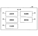
- FIG. 3 is a diagram illustrating a hardware configuration example of the sensor 20 according to the embodiment. 3 includes a transmission unit 21, a reception unit 22, a generation unit 23, a control unit 24, a communication unit 25, and the like.
- the transmission unit 21 transmits a transmission wave that is a frequency-swept radio wave.
- the receiving unit 22 receives a reflected wave (received wave) in which the transmitted wave transmitted by the transmitting unit 21 is reflected by the living body.
- the generation unit 23 generates a beat signal indicating a beat frequency that is a difference between the frequency of the transmission wave transmitted by the transmission unit 21 and the frequency of the reception wave received by the reception unit 22.
- the control unit 24 controls the entire sensor 20, such as the transmission unit 21, the reception unit 22, the generation unit 23, and the communication unit 25.
- the communication unit 25 communicates with the information processing apparatus 10. For example, the communication unit 25 notifies the information processing apparatus 10 of a beat signal indicating the beat frequency at each time generated by the generation unit 23 in real time.
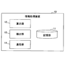
- FIG. 4 is a diagram illustrating an example of a functional block diagram of the information processing apparatus 10 according to the embodiment.
- the information processing apparatus 10 includes a storage unit 11.
- the storage unit 11 is realized using, for example, the auxiliary storage device 102 or the like.
- the storage unit 11 stores, for example, data calculated by the calculation unit 12.
- the information processing apparatus 10 includes a calculation unit 12, a detection unit 13, and a communication unit 14. Each of these units is realized by processing that one or more programs installed in the information processing apparatus 10 cause the CPU 104 of the information processing apparatus 10 to execute.
- the calculation unit 12 performs a Fourier transform on the beat signal acquired from the sensor 20 to calculate the spectrum intensity (distance spectrum) at each distance from the sensor 20. In addition, the calculation unit 12 calculates data of a waveform (hereinafter referred to as “time-series waveform”) indicating the time change of the intensity of the distance spectrum for each distance.
- time-series waveform a waveform
- the detection unit 13 detects the respiration of the living body based on the time-series waveform calculated by the calculation unit 12. Moreover, the detection part 13 detects the movement of the said biological body, or the state of the respiratory stop of the said biological body based on the time-sequential waveform with respect to the distance which detected the biological body's respiration.
- the communication unit 14 transmits a predetermined notification to an external device or the like based on the information detected by the detection unit 13.
- FIG. 5 is a diagram for explaining a transmission wave and a reception wave transmitted and received by the sensor 20.
- the sensor 20 is a so-called FM-CW radar sensor, and transmits a frequency-swept radio wave as a transmission wave 501. Then, the sensor 20 outputs a beat signal indicating the beat frequency f b that is a difference between the frequencies of the transmission wave 501 and the reception wave 502 to the information processing apparatus 10.
- the beat frequency f b the frequency shift width ⁇ F of the transmission wave 501, the modulation period T, and the round-trip propagation delay time t d until the transmission wave 501 is received as the reception wave 502 are expressed by the following formula (1): The relationship holds.
- the information processing apparatus 10 based on the waveform representing the beat frequency f b by each object obtained from the sensor 20 can calculate the distance to each object.
- the beat frequency f b by the object away from the sensor 20 is changed low, since the beat frequency f b by the object approaching the sensor 20 changes high based on the change of the beat frequency f b, movement of an object Speed can also be calculated.
- FIG. 6 is a flowchart illustrating an example of processing of the detection apparatus 1.
- step S1 the generation unit 23 of the sensor 20 determines the difference between the frequency of the transmission wave and the frequency of the reception wave based on the transmission wave transmitted by the transmission unit 21 and the reception wave received by the reception unit 22. A beat signal indicating a certain beat frequency is generated.
- the calculation unit 12 of the information processing device 10 performs fast Fourier transform (Fast Fourier Transform, FFT) on the generated beat signal, and the spectral intensity at each distance from the sensor 20 according to each frequency. (Distance spectrum) is calculated (step S2).
- FFT Fast Fourier Transform
- the calculation unit 12 of the information processing apparatus 10 stores the calculated distance spectrum in the storage unit 11 for a predetermined period (step S3).
- the calculation unit 12 of the information processing device 10 calculates a time series waveform for each distance (each sample point in the distance direction, Index) based on the distance spectrum of a predetermined period, and for each calculated time series waveform Filtering is performed to remove noise (step S4).
- filter processing such as DC (Direct-Current) cut, low-pass filter (Low-pass filter, LPF), and linear DC cut may be performed. Note that this filtering process need not be performed.
- the calculation unit 12 of the information processing apparatus 10 calculates a time-series waveform for each distance after the filter process, and stores it in the storage unit 11 (step S5).
- the detection unit 13 of the information processing apparatus 10 extracts a time series waveform due to respiration of the living body based on the time series waveform for each distance (step S6).
- the detection unit 13 of the information processing apparatus 10 outputs the distance corresponding to the extracted time-series waveform and the extracted time-series waveform as a distance from the living body and a time-series waveform due to respiration of the living body (step) S7).
- the detection unit 13 may display the distance and the time series waveform on a screen or the like.
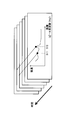
- FIG. 7 is a diagram for explaining a time-series waveform for each distance.
- FIG. 7A shows an example of a distance spectrum at the time of each measurement in the predetermined period in step S3.
- the horizontal axis is the distance from the sensor 20 (distance according to the frequency of the beat frequency)
- the vertical axis is the intensity of the beat frequency.
- FIG. 7B and 7C show examples of time-series waveforms for the distances 511 and 512 in the distance spectrum of FIG. 7A in step S5, respectively.
- FIG. 7B is an example of a time-series waveform due to respiration of a living body.
- distance 511 and waveform data shown in FIG. 7B are output.
- the distance spectrum at the distance where the living body exists, for example, the distance between the sensor 20 and the living body fluctuates due to repeated expansion and contraction of the chest of the living body. Therefore, as shown in FIG. A predetermined time change occurs.
- FIG. 7C is an example of a time-series waveform due to noise.
- the distance from the sensor 20 does not fluctuate periodically in a water tank, a wall, furniture, or the like
- the fluctuation in the intensity of the beat frequency is small compared to a living body.
- the cycle of fluctuation is different from the cycle due to respiration of a living body. Therefore, in the embodiment, a waveform indicating the temporal change in the intensity of the beat frequency with respect to each distance is acquired and accumulated, and a waveform that satisfies a predetermined criterion is detected as being due to respiration of the living body.
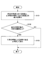
- FIG. 8 is a flowchart illustrating an example of processing for extracting a time-series waveform due to respiration of a living body.
- FIG. 9 is a diagram for explaining an example of processing for extracting a time-series waveform due to respiration of a living body.
- a processing target distance one of the distances in the distance spectrum. The following processing is performed on a time-series waveform that is a waveform showing the temporal change in the intensity of the beat frequency for each distance in the distance spectrum.
- step S101 the detection unit 13 calculates the difference between the intensity at a predetermined time and the intensity at a time ⁇ t seconds after the predetermined time in the time-series waveform with respect to the distance to be processed.
- the detection unit 13 determines whether or not the calculated absolute value of the difference is equal to or greater than a predetermined threshold (step S102).
- step S102 If the calculated absolute value of the difference is not equal to or greater than the predetermined threshold (NO in step S102), the process is terminated.
- step S102 When the calculated absolute value of the difference is equal to or greater than a predetermined threshold (YES in step S102), the detection unit 13 determines that the time-series waveform is a time-series waveform due to the respiration of the living body and extracts the step (step). S103), the process is terminated.
- the detection unit 13 determines the intensity at the predetermined time 701 in FIG. 9 (an example of “first time”) and the time 702 after ⁇ t seconds from the predetermined time (an example of “second time”). It may be determined only by the difference 703 from the intensity in).
- the detection unit 13 repeatedly executes the process of step S103 at a predetermined cycle, and determines and extracts a time-series waveform due to living body respiration when the difference in each cycle is equal to or greater than a threshold value. Also good.
- the value obtained by accumulating the absolute value of the difference in a predetermined period is equal to or greater than a predetermined threshold value, it may be extracted by determining that it is a time series waveform due to respiration of a living body.
- differences 703 an example of “first value”
- 704 an example of “second value”
- the time-series waveform for a plurality of distances is a time-series waveform due to respiration of the living body
- only the time-series waveform for the distance closest to the sensor 20 may be extracted as the time-series waveform due to respiration of the living body.
- the breathing of the closest person can be extracted from the sensor 20.
- the respiratory waveforms are mixed and detected, so it is difficult to extract a time-series waveform for the closest distance from the sensor 20.
- FIG. 10 is a diagram for explaining an example of processing for extracting a time-series waveform due to respiration of a living body.
- the detection unit 13 may determine and extract whether or not the time series waveform is a time series waveform due to respiration of a living body based on the maximum value and the minimum value of the intensity in the time series waveform. In this case, for example, the detection unit 13 calculates the difference between the maximum value and the minimum value of the intensity in a predetermined cycle for each time-series waveform for each distance, and the time-series waveform in which the difference is equal to or greater than a predetermined threshold value. May be extracted by determining that it is a time-series waveform due to respiration of a living body.
- FIG. 10 shows an example of a difference 713 between the maximum value 711 and the minimum value 712 in a predetermined period in a time-series waveform with respect to a predetermined distance.
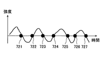
- FIG. 11 is a diagram for explaining an example of processing for extracting a time-series waveform due to respiration of a living body.
- the detection unit 13 corrects each point of the time-series waveform for each distance by 0 points such that the average value of the intensity of the time-series waveform in a predetermined period is 0, and the intensity value in the predetermined period is other than 0. Whether or not the patient is breathing may be determined based on the number of times of crossing. In this case, for example, the detection unit 13 converts the number of crossings in a predetermined period into a frequency or a period, and a time-series waveform that is within the range of the respiration frequency (for example, 0.15 Hz to 0.5 Hz) or the period of the living body. May be extracted by determining that it is a time-series waveform due to respiration of a living body.
- FIG. 11A shows time points 721 to 727 that cross 0 after zero point correction in an example of a time-series waveform due to respiration of a living body. If the frequency of each time point 721 to 727 is within the range of the respiration frequency of the living body, it is determined that the time series waveform is due to the respiration of the living body.
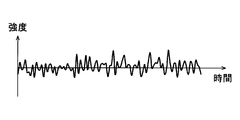
- FIG. 11B shows an example of a waveform due to noise or the like. In such a waveform, the frequency at each time point where the zero crossing after the zero point correction is not within the range of the respiration frequency of the living body is determined not to be a time-series waveform due to respiration of the living body.
- the detection unit 13 has a frequency or period in which the difference between the maximum value and the minimum value shown in FIG. 10 is equal to or greater than a predetermined threshold value and crosses 0 after zero point correction shown in FIG.
- a time series waveform within the range of the frequency or cycle of respiration may be extracted by determining that it is a time series waveform due to respiration of a living body.
- the detection unit 13 uses the difference between the maximum value and the minimum value shown in FIG. 10 as an evaluation value, and the frequency or cycle crossing 0 after zero point correction shown in FIG.
- the waveform is a time series waveform due to respiration of a living body.
- FIG. 12 is a diagram illustrating an example of processing for extracting a time-series waveform due to respiration of a living body.
- the detection unit 13 performs matching with one or more ideal respiratory waveforms stored in advance or a sin wave (sine wave) having a specific period for each of the time-series waveforms for each distance, and a time series based on respiration of a living body. You may determine whether it is a waveform. In this case, for example, the detection unit 13 calculates a correlation coefficient between the time-series waveform and each waveform stored in advance, and when the calculated correlation coefficient value is equal to or greater than a predetermined threshold, The time series waveform may be determined and extracted.
- a sin wave sine wave
- the detection unit 13 has a difference between the maximum value and the minimum value of the intensity shown in FIG. 10 equal to or larger than a predetermined threshold value, and each waveform and correlation coefficient value shown in FIG. If it is equal to or greater than the threshold, it may be extracted by determining that it is a time-series waveform due to respiration of the living body. Accordingly, the time series waveform to be matched can be limited to those satisfying the conditions such as the difference between the maximum value and the minimum value, so that the processing time can be shortened.
- FIG. 13 is a diagram illustrating an example of processing for extracting a time-series waveform due to respiration of a living body.
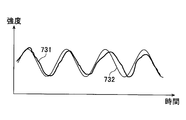
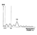
- the detection unit 13 performs a fast Fourier transform on the time-series waveform for each distance, and obtains a time-series waveform having an intensity peak within the range of the respiration frequency of the living body (for example, 0.15 Hz to 0.5 Hz). You may extract by determining with it being a time-sequential waveform by the respiration of a biological body.
- FIG. 13A shows an intensity peak when fast Fourier transform is performed on an example of a time-series waveform due to respiration of a living body.
- the peak 731 is within the range of the respiration frequency of the living body, it is determined that the time series waveform is due to the respiration of the living body.
- FIG. 13B shows an intensity peak when fast Fourier transform is performed on an example of a time-series waveform due to noise or the like.
- the peak 732 is not within the range of the respiration frequency of the living body, it is determined that it is not a time-series waveform due to respiration of the living body.
- the present embodiment it is possible to determine whether the time-series waveform is due to the respiration of the living body for each distance from the sensor 20. For this reason, even when one living body and another living body (for example, a family, a dog, a cat, etc.) located farther from the sensor 20 than the one living body are sleeping side by side, the breathing of the other living body , It is possible to detect respiration by the one living body while suppressing erroneous detection as respiration of the one living body.
- one living body and another living body for example, a family, a dog, a cat, etc.
- the second embodiment is the same as the first embodiment except for a part thereof, and thus description thereof will be omitted as appropriate. Below, description is abbreviate
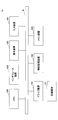
- FIG. 14 is a flowchart illustrating an example of processing of the detection apparatus 1.
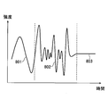
- FIG. 15 is a diagram for explaining a time-series waveform by an operation such as rising.
- step S201 the detection unit 13 detects respiration of a living body at a predetermined distance based on a time-series waveform for each distance.
- the detection unit 13 determines whether or not a time-series waveform due to an operation such as rising at the predetermined distance has been detected (step S202).
- the detection unit 13 detects respiration of the living body at the predetermined distance based on the subsequent time-series waveform with respect to the predetermined distance. Whether or not (step S203).
- step S203 If the respiration of the living body is detected (YES in step S203), the detection unit 13 waits for a predetermined time, and then proceeds to the process of step S202.
- the detection unit 13 determines that it is a sputum (step S204) and ends the process. In addition, when it determines with a bag, you may make it notify a predetermined apparatus, for example.
- a waveform different from the respiration waveform for example, the respiration waveform and the amplitude are the same, and the respiration waveform and period are If a waveform 803 having an amplitude equal to or smaller than a predetermined threshold is detected after detecting a different waveform 802, it is determined to be ⁇ . Thereby, for example, in the care facility, the caregiver can be notified that the care receiver has woken up from the bed and started wrinkles.
- the detection unit 13 may determine that the living body has moved when the distance to the time-series waveform due to the breathing of the living body varies with time, and thus can determine that the living body has moved.
- the detection unit 13 determines whether or not respiration of the living body is detected at the predetermined distance based on the subsequent time-series waveform with respect to the predetermined distance. Is determined (step S205).
- step S205 If the respiration of the living body is detected (YES in step S205), the detection unit 13 waits for a predetermined time and then proceeds to the process of step S202.
- the detection unit 13 When the respiration of the living body is not detected (NO in step S205), the detection unit 13 thereafter time-series waveforms with respect to the predetermined distance and a time series with respect to a distance within a predetermined range (for example, within 60 cm) from the predetermined distance. Based on the waveform, it is determined whether or not the respiration of the living body is detected within the predetermined period in the vicinity of the predetermined distance (step S206).
- a predetermined range for example, within 60 cm
- step S207 determines that it is an apnea state (step S207), and proceeds to the process of step S202.
- the detection unit 13 determines that the living body is in a dangerous state such as a heartbeat stop (step S208) and ends the process. To do.
- a notification may be made to a predetermined device.
- the third embodiment is the same as the first embodiment except for a part thereof, and thus description thereof will be omitted as appropriate. Below, description is abbreviate
- FIG. 16 is a diagram illustrating an example in which the sensor 20 is installed on a moving body such as a vehicle. As shown in FIG. 16, in the moving body 811, the sensor 20 is installed in the vicinity of the driver's seat 812, for example, at a position such as a steering wheel, a speed meter, or a driver sun visor.
- the detection unit 13 determines that the time series waveform for a plurality of distances is a time series waveform due to respiration of the living body
- only the time series waveform for the distance closest to the sensor 20 is used as the time series due to respiration of the living body. Extract as a waveform.
- the present embodiment by extracting a time-series waveform for a distance that is closest (small) from the sensor 20 among time-series waveforms determined to be a time-series waveform due to respiration, other crew members are extracted. It is possible to suppress the influence of the reflected wave and observe the time-series waveform due to the driver's breathing.
- a correlation coefficient between the detected time series waveform due to breathing and a time series waveform caused by breathing when there is sleepiness or fatigue stored in advance is calculated, and the calculated correlation coefficient value is predetermined. If the threshold is equal to or greater than the threshold, the driver may be determined to have drowsiness or fatigue. Whether the driver is in a dangerous state may be determined, for example, by the same processing as in the second embodiment described above.
- 4th Embodiment demonstrates the example which detects the respiration of the human body in bathing using the detection apparatus 1 which concerns on 1st Embodiment.
- the fourth embodiment is the same as the first embodiment except for a part thereof, and thus description thereof will be omitted as appropriate. Below, description is abbreviate
- FIG. 17 is a diagram illustrating an example in which the sensor 20 is installed in a bathroom.
- the sensor 20 is installed at a position in the vicinity of the bather 822 in the bathroom 821.
- the sensor 20 is installed around the bathtub 823, for example, at the edge of the bathtub, and the center 824 in the irradiation direction of the radio wave from the sensor 20 is set higher than the bathtub 823, that is, in the horizontal direction. You may point in the upward direction. Thereby, the influence of the reflected wave by the water surface can be suppressed.
- the intensity of the reflected wave due to the water in the bathtub becomes relatively strong, it may be difficult to observe the presence or absence of the human body and the state thereof.
- the present embodiment using the fact that the head located above the water surface in the bathtub moves in response to breathing, the time series waveform due to the movement of the head, the breathing of the human body during bathing The presence or absence can be detected. Thereby, based on the time-series waveform by a bather's respiration, it can be determined whether it is drowning, whether it is in a dangerous state such as a heartbeat stop due to heat shock or the like.
- the fifth embodiment is the same as the first embodiment except for a part thereof, and thus description thereof will be omitted as appropriate. Below, description is abbreviate
- FIG. 18 is a diagram illustrating an example of an information processing system 50 having the detection apparatus 1.
- the information processing system 50 includes the detection device 1, the server device 30, the terminals 40-1, 40-2,... (Hereinafter simply referred to as “terminal 40” when it is not necessary to distinguish between them). Have.
- the detecting device 1, the server device 30, and the terminal 40 are connected so as to be able to communicate via a network 60 such as a LAN (Local Area Network), a wireless LAN, Bluetooth (registered trademark), a mobile phone network, and the Internet.
- a network 60 such as a LAN (Local Area Network), a wireless LAN, Bluetooth (registered trademark), a mobile phone network, and the Internet.
- the server device 30 is an information processing device (computer) for a server, and stores data notified from the detection device 1 in association with identification information of the detection device 1, for example.
- the terminal 40 is an information processing apparatus such as a desktop PC (Personal Computer), a notebook PC, a tablet PC, or a smartphone.
- the terminal 40 logs in to the server device 30 and displays data relating to the respiration and state detected by the detection device 1.
- the terminal 40 may directly acquire data from the detection device 1 and display it without using the server device 30.
- notifications such as sputum and cardiopulmonary arrest may be transmitted from the detection device 1 to the terminal 40.
- ⁇ Others> In each of the above-described embodiments, an example in which a human body is targeted as a living body has been described. However, for example, a living body of an animal other than a human such as a dog or a cat may be targeted.
- a wild animal can be detected by installing the sensor 20 in a field or a forest and recognizing the respiration of the wild animal that has appeared. In this case, according to the detection apparatus 1 which concerns on embodiment, the presence or absence of a wild animal can be confirmed, suppressing the influence of the movement of a plant, rainwater, etc. by a wind.
- Each functional unit of the information processing apparatus 10 may be realized by, for example, cloud computing including one or more computers. Further, the information processing apparatus 10 and the sensor 20 may be configured as an integrated apparatus. The sensor 20 may have at least a part of each functional unit of the information processing apparatus 10. The information processing apparatus 10 may have at least a part of the functional units of the sensor 20.
Landscapes
- Engineering & Computer Science (AREA)
- Radar, Positioning & Navigation (AREA)
- Remote Sensing (AREA)
- Physics & Mathematics (AREA)
- Computer Networks & Wireless Communication (AREA)
- General Physics & Mathematics (AREA)
- Health & Medical Sciences (AREA)
- Life Sciences & Earth Sciences (AREA)
- Biophysics (AREA)
- Heart & Thoracic Surgery (AREA)
- Oral & Maxillofacial Surgery (AREA)
- Physiology (AREA)
- Electromagnetism (AREA)
- Pathology (AREA)
- Biomedical Technology (AREA)
- Dentistry (AREA)
- Medical Informatics (AREA)
- Molecular Biology (AREA)
- Surgery (AREA)
- Animal Behavior & Ethology (AREA)
- General Health & Medical Sciences (AREA)
- Public Health (AREA)
- Veterinary Medicine (AREA)
- Measurement Of The Respiration, Hearing Ability, Form, And Blood Characteristics Of Living Organisms (AREA)
Abstract
情報処理装置において、センサにより送信された周波数掃引された電波である送信波と、前記センサにより受信された前記送信波の反射波との差分であるビート信号に基づき距離スペクトルを算出し、前記センサからの各距離について前記距離スペクトルの強度の時間変化を示す時系列波形を算出する算出部と、前記時系列波形に基づき、生体の呼吸を検出する検出部と、を有する。
Description
本発明は、情報処理装置、及び検出装置に関する。
従来、FM-CW(Frequency Modulated Continuous Wave)レーダセンサを用いて、人や物との距離を測定する技術が知られている。FM-CWレーダセンサは、周波数掃引された電波を送信波とし、送信波と反射波の周波数の差分であるビート周波数を算出し、算出したビート周波数に基づいて、センサから測定対象までの距離を算出する。
また、このFM-CWレーダセンサを用いて、生体の呼吸を検出する技術も知られている(例えば、特許文献1、2を参照)。
しかしながら、従来技術では、家具、雑貨、壁、床、天井等の生体以外の物を、生体として検出してしまう場合があるという問題がある。
また、例えば、測定対象の生体の近くに水槽や飲料容器等がある場合、送信波の周波数によっては、水による反射波が比較的強くなるため、呼吸の有無を誤判定してしまう場合があるという問題がある。
そこで、一側面では、生体の検出精度を向上させることができる技術を提供することを目的とする。
一つの案では、センサにより送信された周波数掃引された電波である送信波と、前記センサにより受信された前記送信波の反射波との差分であるビート信号に基づき距離スペクトルを算出し、前記センサからの各距離について前記距離スペクトルの強度の時間変化を示す時系列波形を算出する算出部と、前記時系列波形に基づき、生体の呼吸を検出する検出部と、を有する情報処理装置が提供される。
一側面によれば、生体の検出精度を向上させることができる。
[第1の実施形態]
以下、図面に基づいて本発明の実施形態を説明する。
以下、図面に基づいて本発明の実施形態を説明する。
<全体構成>
図1は、実施形態に係る検出装置1の構成例を示す図である。図1において、検出装置1は、情報処理装置10、及びセンサ20を有する。
図1は、実施形態に係る検出装置1の構成例を示す図である。図1において、検出装置1は、情報処理装置10、及びセンサ20を有する。
情報処理装置10は、例えば、PC(Personal Computer)、組み込みシステム等である。
センサ20は、例えば、FM-CWレーダセンサである。センサ20は、例えば、半導体基板上に形成した集積回路により実現されてもよい。
情報処理装置10とセンサ20とは、例えば、バス等を介して接続される。
情報処理装置10は、センサ20から取得した信号に基づき、生体の有無、生体との距離、及び生体の呼吸の状態等を検出する。
<ハードウェア構成>
≪情報処理装置≫
図2は、実施形態に係る情報処理装置10のハードウェア構成例を示す図である。図2の情報処理装置10は、それぞれバスBで相互に接続されているドライブ装置100、補助記憶装置102、メモリ装置103、CPU104、インタフェース装置105、表示装置106、及び入力装置107等を有する。
≪情報処理装置≫
図2は、実施形態に係る情報処理装置10のハードウェア構成例を示す図である。図2の情報処理装置10は、それぞれバスBで相互に接続されているドライブ装置100、補助記憶装置102、メモリ装置103、CPU104、インタフェース装置105、表示装置106、及び入力装置107等を有する。
情報処理装置10での処理を実現する情報処理プログラムは、記録媒体101によって提供される。情報処理プログラムを記録した記録媒体101がドライブ装置100にセットされると、情報処理プログラムが記録媒体101からドライブ装置100を介して補助記憶装置102にインストールされる。但し、情報処理プログラムのインストールは必ずしも記録媒体101より行う必要はなく、ネットワークを介して他のコンピュータよりダウンロードするようにしてもよい。補助記憶装置102は、インストールされた情報処理プログラムを格納すると共に、必要なファイルやデータ等を格納する。
メモリ装置103は、プログラムの起動指示があった場合に、補助記憶装置102からプログラムを読み出して格納する。CPU104は、メモリ装置103に格納されたプログラムに従って情報処理装置10に係る機能を実現する。インタフェース装置105は、ネットワークに接続するためのインタフェースとして用いられる。表示装置106はプログラムによるGUI(Graphical User Interface)等を表示する。入力装置107はタッチパネル及びボタン等で構成され、様々な操作指示を入力させるために用いられる。
なお、記録媒体101の一例としては、CD-ROM、DVDディスク、又はUSBメモリ等の可搬型の記録媒体が挙げられる。また、補助記憶装置102の一例としては、HDD(Hard Disk Drive)又はフラッシュメモリ等が挙げられる。記録媒体101及び補助記憶装置102のいずれについても、コンピュータ読み取り可能な記録媒体に相当する。
≪センサ≫
図3は、実施形態に係るセンサ20のハードウェア構成例を示す図である。図3のセンサ20は、送信部21、受信部22、生成部23、制御部24、及び通信部25等を有する。
図3は、実施形態に係るセンサ20のハードウェア構成例を示す図である。図3のセンサ20は、送信部21、受信部22、生成部23、制御部24、及び通信部25等を有する。
送信部21は、周波数掃引された電波である送信波を送信する。
受信部22は、送信部21により送信された送信波が、生体により反射された反射波(受信波)を受信する。
生成部23は、送信部21により送信された送信波の周波数と、受信部22により受信された受信波の周波数との差分であるビート周波数を示すビート信号を生成する。
制御部24は、送信部21、受信部22、生成部23、及び通信部25等の、センサ20の全体の制御を行う。
通信部25は、情報処理装置10との通信を行う。通信部25は、例えば、生成部23により生成された各時刻におけるビート周波数を示すビート信号を、リアルタイムで情報処理装置10に通知する。
<機能構成>
次に、図4を参照し、情報処理装置10の機能構成について説明する。図4は、実施形態に係る情報処理装置10の機能ブロック図の一例を示す図である。
次に、図4を参照し、情報処理装置10の機能構成について説明する。図4は、実施形態に係る情報処理装置10の機能ブロック図の一例を示す図である。
情報処理装置10は、記憶部11を有する。記憶部11は、例えば、補助記憶装置102等を用いて実現される。
記憶部11は、例えば、算出部12により算出されるデータ等を記憶する。
また、情報処理装置10は、算出部12、検出部13、及び通信部14を有する。これら各部は、情報処理装置10にインストールされた1以上のプログラムが、情報処理装置10のCPU104に実行させる処理により実現される。
算出部12は、センサ20から取得したビート信号をフーリエ変換し、センサ20からの各距離でのスペクトル強度(距離スペクトル)を算出する。また、算出部12は、各距離について、距離スペクトルの強度の時間変化を示す波形(以下で「時系列波形」と称する。)のデータを算出する。
検出部13は、算出部12により算出された時系列波形に基づき、生体の呼吸を検出する。また、検出部13は、生体の呼吸を検出した距離に対する時系列波形に基づき、当該生体の移動、または当該生体の呼吸停止の状態を検出する。
通信部14は、検出部13により検出された情報に基づいて、外部装置等に所定の通知を送信する。
<FM-CWレーダの原理>
次に、図5を参照して、FM-CWレーダ用のセンサ20の原理の処理について説明する。図5は、センサ20が送受信する送信波、及び受信波について説明する図である。
次に、図5を参照して、FM-CWレーダ用のセンサ20の原理の処理について説明する。図5は、センサ20が送受信する送信波、及び受信波について説明する図である。
センサ20は、いわゆるFM-CWレーダ用のセンサであり、周波数掃引された電波を送信波501として送信する。そして、センサ20は、送信波501と受信波502の周波数の差分であるビート周波数fbを示すビート信号を情報処理装置10に出力する。
ここで、ビート周波数fb、送信波501の周波数の変移幅ΔF、変調周期T、送信波501が受信波502として受信されるまでの往復伝搬遅延時間tdには、以下の式(1)の関係が成り立つ。
fb/td = ΔF/T ・・・(1)
往復伝搬遅延時間td、光速c、送信波501を反射した生体等の物体とセンサ20との距離Rには、以下の式(2)の関係が成り立つ。
往復伝搬遅延時間td、光速c、送信波501を反射した生体等の物体とセンサ20との距離Rには、以下の式(2)の関係が成り立つ。
td = 2R/c ・・・(2)
したがって、式(1)、(2)より、以下の式(3)が導かれる。
したがって、式(1)、(2)より、以下の式(3)が導かれる。
fb = ΔF2R/Tc ・・・(3)
よって、センサ20からの距離Rが比較的近い物体によるビート周波数fbは比較的低く、距離Rが比較的遠い物体によるビート周波数fbは比較的高くなる。そのため、情報処理装置10は、センサ20から取得した各物体によるビート周波数fbを示す波形に基づき、各物体までの距離を算出できる。なお、ドップラー効果により、センサ20から遠ざかる物体によるビート周波数fbは低く変化し、センサ20に近づく物体によるビート周波数fbは高く変化するため、ビート周波数fbの変化に基づいて、物体の移動速度も算出できる。
よって、センサ20からの距離Rが比較的近い物体によるビート周波数fbは比較的低く、距離Rが比較的遠い物体によるビート周波数fbは比較的高くなる。そのため、情報処理装置10は、センサ20から取得した各物体によるビート周波数fbを示す波形に基づき、各物体までの距離を算出できる。なお、ドップラー効果により、センサ20から遠ざかる物体によるビート周波数fbは低く変化し、センサ20に近づく物体によるビート周波数fbは高く変化するため、ビート周波数fbの変化に基づいて、物体の移動速度も算出できる。
<処理>
次に、図6を参照し、検出装置1の処理について説明する。図6は、検出装置1の処理の一例を示すフローチャートである。
次に、図6を参照し、検出装置1の処理について説明する。図6は、検出装置1の処理の一例を示すフローチャートである。
まず、ステップS1において、センサ20の生成部23は、送信部21により送信された送信波と、受信部22により受信された受信波とに基づき、送信波の周波数と受信波の周波数の差であるビート周波数を示すビート信号を生成する。
続いて、情報処理装置10の算出部12は、生成されたビート信号に対して高速フーリエ変換(Fast Fourier Transform、FFT)を実行し、各周波数に応じたセンサ20からの各距離でのスペクトル強度(距離スペクトル)を算出する(ステップS2)。
続いて、情報処理装置10の算出部12は、算出した距離スペクトルを、所定期間、記憶部11に記憶させる(ステップS3)。
続いて、情報処理装置10の算出部12は、所定期間の距離スペクトルに基づいて、各距離(距離方向の各標本点、Index)に対する時系列波形を算出し、算出した各時系列波形に対してフィルタ処理を行い、ノイズの除去等を行う(ステップS4)。ここで、例えば、DC(Direct Current)カット、ローパスフィルタ(Low-pass filter、LPF)、線形DCカット等のフィルタ処理を行ってもよい。なお、このフィルタ処理は行わなくともよい。
続いて、情報処理装置10の算出部12は、フィルタ処理後の、各距離に対する時系列波形を算出して、記憶部11に記憶させる(ステップS5)。
続いて、情報処理装置10の検出部13は、各距離に対する時系列波形に基づいて、生体の呼吸による時系列波形を抽出する(ステップS6)。
続いて、情報処理装置10の検出部13は、抽出した時系列波形に対応する距離、及び抽出した時系列波形を、生体との距離、及び当該生体の呼吸による時系列波形として出力する(ステップS7)。ここで、検出部13は、距離や時系列波形を画面等に表示させてもよい。
図7は、各距離に対する時系列波形について説明する図である。図7Aでは、ステップS3の、所定期間の各計測時における距離スペクトルの例が示されている。図7Aの例では、横軸はセンサ20からの距離(ビート周波数の周波数に応じた距離)であり、縦軸はビート周波数の強度である。
図7B、図7Cでは、それぞれ、ステップS5の、図7Aの距離スペクトルにおける距離511、距離512に対する時系列波形の例が示されている。図7Bは、生体の呼吸による時系列波形の例であり、ステップS7の処理において、距離511と、図7Bに示す波形のデータが出力される。距離スペクトルにおいて、生体が存在する距離では、例えば、生体の胸部が膨張、及び収縮を繰り返すことにより、センサ20と生体との距離が変動するため、図7Bに示すように、ビート周波数の強度が所定の時間変化を生ずる。
一方、図7Cは、ノイズによる時系列波形の例である。例えば、水槽、壁、家具等は、センサ20との距離が周期的に変動することはないため、生体と比べてビート周波数の強度の変動は小さい。また、変動の周期等も、生体の呼吸による周期等とは異なっている。そこで、実施形態では、各距離に対するビート周波数の強度の時間変化を示す波形を取得、蓄積し、所定の基準を満たす波形を、生体の呼吸によるものとして検出する。
≪生体の呼吸による時系列波形の抽出処理の例1≫
次に、図8、図9を参照し、検出部13によるステップS6の生体の呼吸による時系列波形の抽出する処理の一例について説明する。図8は、生体の呼吸による時系列波形の抽出する処理の一例を示すフローチャートである。図9は、生体の呼吸による時系列波形の抽出する処理の一例について説明する図である。以下では、距離スペクトルにおける各距離のうちの一の距離を、処理対象とする距離と称する。以下の処理は、距離スペクトルにおける各距離に対するビート周波数の強度の時間変化を示す波形である時系列波形に対して実行される。
次に、図8、図9を参照し、検出部13によるステップS6の生体の呼吸による時系列波形の抽出する処理の一例について説明する。図8は、生体の呼吸による時系列波形の抽出する処理の一例を示すフローチャートである。図9は、生体の呼吸による時系列波形の抽出する処理の一例について説明する図である。以下では、距離スペクトルにおける各距離のうちの一の距離を、処理対象とする距離と称する。以下の処理は、距離スペクトルにおける各距離に対するビート周波数の強度の時間変化を示す波形である時系列波形に対して実行される。
ステップS101において、検出部13は、処理対象とする距離に対する時系列波形において、所定の時刻における強度と、当該所定の時刻からΔt秒後の時刻における強度との差分を算出する。
続いて、検出部13は、算出した差分の絶対値が、所定の閾値以上であるか否かを判定する(ステップS102)。
算出した差分の絶対値が、所定の閾値以上でない場合(ステップS102でNO)、処理を終了する。
算出した差分の絶対値が、所定の閾値以上である場合(ステップS102でYES)、検出部13は、当該時系列波形を、生体の呼吸による時系列波形であると判定して抽出し(ステップS103)、処理を終了する。ステップS103において、検出部13は、図9の所定の時刻701(「第1の時刻」の一例)における強度と、当該所定の時刻からΔt秒後の時刻702(「第2の時刻」の一例)における強度との差分703のみで判断してもよい。または、検出部13は、所定の周期でステップS103の処理を繰り返して実行し、各周期における差分がそれぞれ閾値以上である場合に、生体の呼吸による時系列波形であると判定して抽出してもよい。
あるいは、差分の絶対値を所定期間において累積した値が所定の閾値以上である場合に、生体の呼吸による時系列波形であると判定して抽出してもよい。この場合、所定期間における各時刻における強度と、当該各時刻からΔt秒後の時刻における強度との各差分703(「第1の値」の一例)、704(「第2の値」の一例)、・・・を算出し、各差分703、704、・・・を累積した値が閾値以上である場合に、生体の呼吸による時系列波形であると判定して抽出してもよい。
なお、複数の距離に対する時系列波形について、生体の呼吸による時系列波形であると判定した場合、センサ20から最も近い距離に対する時系列波形のみを、生体の呼吸による時系列波形として抽出してもよい。これにより、例えば、複数の人が並んでいる場合に、センサ20から最も近い人の呼吸を抽出できる。なお、従来技術では、複数人が並んでいる場合、それぞれの呼吸波形が混ざって検出されてしまうため、センサ20から最も近い距離に対する時系列波形を抽出することは困難である。
≪生体の呼吸による時系列波形の抽出処理の例2≫
次に、図10を参照し、検出部13によるステップS6の生体の呼吸による時系列波形の抽出する処理の一例について説明する。図10は、生体の呼吸による時系列波形の抽出する処理の一例について説明する図である。
次に、図10を参照し、検出部13によるステップS6の生体の呼吸による時系列波形の抽出する処理の一例について説明する。図10は、生体の呼吸による時系列波形の抽出する処理の一例について説明する図である。
検出部13は、時系列波形における強度の最大値と最小値とに基づいて、当該時系列波形が生体の呼吸による時系列波形であるか否かを判定して抽出してもよい。この場合、検出部13は、例えば、各距離に対する時系列波形の各々について、所定の周期における強度の最大値と最小値との差分を算出し、当該差分が所定の閾値以上である時系列波形を、生体の呼吸による時系列波形であると判定して抽出してもよい。図10では、所定の距離に対する時系列波形における所定の周期における最大値711と最小値712との差分713の例が示されている。
≪生体の呼吸による時系列波形の抽出処理の例3≫
次に、図11を参照し、検出部13によるステップS6の生体の呼吸による時系列波形の抽出する処理の一例について説明する。図11は、生体の呼吸による時系列波形の抽出する処理の一例について説明する図である。
次に、図11を参照し、検出部13によるステップS6の生体の呼吸による時系列波形の抽出する処理の一例について説明する。図11は、生体の呼吸による時系列波形の抽出する処理の一例について説明する図である。
検出部13は、各距離に対する時系列波形の各々について、例えば、所定期間における時系列波形の強度の平均値が0となる等のように0点補正し、所定期間における強度の値が0以外に変化した(クロスした)回数をもとに呼吸か否か判断してもよい。この場合、検出部13は、例えば、所定期間においてクロスした回数を周波数または周期に換算し、生体の呼吸の周波数(例えば、0.15Hz乃至0.5Hz)または周期の範囲内である時系列波形を、生体の呼吸による時系列波形であると判定して抽出してもよい。図11Aでは、生体の呼吸による時系列波形の例における、0点補正後の0をクロスした各時点721乃至727が示されている。各時点721乃至727の周波数が、生体の呼吸の周波数の範囲内であれば、生体の呼吸による時系列波形であると判定される。図11Bでは、ノイズ等による波形の例が示されている。このような波形において、0点補正後の0をクロスした各時点の周波数は、生体の呼吸の周波数の範囲内ではないため、生体の呼吸による時系列波形でないと判定される。
なお、上述した、生体の呼吸による時系列波形の抽出する各処理を組み合わせて用いることも可能である。例えば、検出部13は、図10に示す強度の最大値と最小値との差分が所定の閾値以上であり、かつ図11Aに示す0点補正後の0をクロスする周波数または周期が、生体の呼吸の周波数または周期の範囲内である時系列波形を、生体の呼吸による時系列波形であると判定して抽出してもよい。または、検出部13は、図10に示す強度の最大値と最小値との差分の値を評価値とし、図11Aに示す0点補正後の0をクロスする周波数または周期と、生体の呼吸の周波数または周期との一致度に応じた重み係数を当該評価値に乗算した値が所定の閾値以上である場合に、生体の呼吸による時系列波形であると判定して抽出してもよい。
≪生体の呼吸による時系列波形の抽出処理の例4≫
次に、図12を参照し、検出部13によるステップS6の生体の呼吸による時系列波形の抽出する処理の一例について説明する。図12は、生体の呼吸による時系列波形の抽出する処理の一例について説明する図である。
次に、図12を参照し、検出部13によるステップS6の生体の呼吸による時系列波形の抽出する処理の一例について説明する。図12は、生体の呼吸による時系列波形の抽出する処理の一例について説明する図である。
検出部13は、各距離に対する時系列波形の各々について、予め記憶されている1以上の理想的な呼吸波形や特定周期のsin波(正弦波)とのマッチングを行い、生体の呼吸による時系列波形か否かを判断してもよい。この場合、検出部13は、例えば、時系列波形と、予め記憶されている各波形との相関係数を算出し、算出した相関係数の値が所定の閾値以上の場合に、生体の呼吸による時系列波形であると判定して抽出してもよい。
なお、上述した、生体の呼吸による時系列波形の抽出する各処理を組み合わせて用いることも可能である。例えば、検出部13は、図10に示す強度の最大値と最小値との差分が所定の閾値以上であり、かつ図12に示す予め記憶されている各波形と相関係数の値が所定の閾値以上の場合に、生体の呼吸による時系列波形であると判定して抽出してもよい。これにより、マッチングの対象とする時系列波形を、最大値と最小値との差分等の条件を満たすものに限定できるため、処理時間を短縮することができる。
≪生体の呼吸による時系列波形の抽出処理の例5≫
次に、図13を参照し、検出部13によるステップS6の生体の呼吸による時系列波形の抽出する処理の一例について説明する。図13は、生体の呼吸による時系列波形の抽出する処理の一例について説明する図である。
次に、図13を参照し、検出部13によるステップS6の生体の呼吸による時系列波形の抽出する処理の一例について説明する。図13は、生体の呼吸による時系列波形の抽出する処理の一例について説明する図である。
検出部13は、各距離に対する時系列波形に対して高速フーリエ変換を行い、生体の呼吸の周波数(例えば、0.15Hz乃至0.5Hz)の範囲内に強度のピークを有する時系列波形を、生体の呼吸による時系列波形であると判定して抽出してもよい。
図13Aでは、生体の呼吸による時系列波形の例について高速フーリエ変換を行った場合の強度のピークが示されている。図13Aでは、ピーク731が生体の呼吸の周波数の範囲内であるため、生体の呼吸による時系列波形であると判定される。
図13Bでは、ノイズ等による時系列波形の例について高速フーリエ変換を行った場合の強度のピークが示されている。図13Bでは、ピーク732が生体の呼吸の周波数の範囲内でないため、生体の呼吸による時系列波形でないと判定される。
なお、上述した、生体の呼吸による時系列波形の抽出する各処理を組み合わせて用いることも可能である。
本実施形態によれば、センサ20からの距離毎に、時系列波形が生体の呼吸によるものか否かを判断できる。このため、一の生体と、当該一の生体よりもセンサ20から離れた位置の他の生体(例えば、家族、犬や猫等)とが並んで寝ていた場合でも、当該他の生体の呼吸を当該一の生体の呼吸と誤検出することを抑制しつつ、当該一の生体による呼吸を検出できる。
[第2の実施形態]
次に、第2の実施形態について説明する。第2の実施形態では、第1の実施形態に係る検出装置1を用いて、徘徊等を検出する例について説明する。
次に、第2の実施形態について説明する。第2の実施形態では、第1の実施形態に係る検出装置1を用いて、徘徊等を検出する例について説明する。
なお、第2の実施形態は一部を除いて第1の実施形態と同様であるため、適宜説明を省略する。以下では、第1の実施形態と共通する部分については説明を省略し、異なる部分についてのみ説明する。なお、第2の実施形態に記載の内容は、第1の実施形態にも適用可能である。
<処理>
次に、図14、図15を参照し、検出装置1の処理について説明する。図14は、検出装置1の処理の一例を示すフローチャートである。図15は、立ち上がり等の動作による時系列波形について説明する図である。
次に、図14、図15を参照し、検出装置1の処理について説明する。図14は、検出装置1の処理の一例を示すフローチャートである。図15は、立ち上がり等の動作による時系列波形について説明する図である。
ステップS201において、検出部13は、各距離に対する時系列波形に基づいて、所定の距離における生体の呼吸を検出する。
続いて、検出部13は、当該所定の距離に対する時系列波形に基づいて、当該所定の距離において立ち上がり等の動作による時系列波形を検出したか否かを判定する(ステップS202)。
当該所定の距離において立ち上がり等の動作を検出した場合(ステップS202でYES)、検出部13は、その後の当該所定の距離に対する時系列波形に基づいて、当該所定の距離において生体の呼吸を検出したか否かを判定する(ステップS203)。
生体の呼吸を検出した場合(ステップS203でYES)、検出部13は、一定時間待機した後、ステップS202の処理に進む。
生体の呼吸を検出しない場合(ステップS203でNO)、検出部13は、徘徊と判定し(ステップS204)、処理を終了する。なお、徘徊と判定した場合は、例えば、所定の装置に通報等を行うようにしてもよい。ここで、図15に示す所定の距離に対する時系列波形において、生体の呼吸による波形801の後、呼吸の波形とは異なる波形、例えば、呼吸の波形と振幅が同様で、呼吸の波形と周期が異なる波形802を検出した後、振幅が所定の閾値以下の波形803が検出された場合、徘徊と判定される。これにより、例えば、介護施設において、被介護者がベッドから起きて徘徊を開始したことを、介護者に通知することができる。
また、検出部13は、生体の呼吸による時系列波形に対する距離が時間経過に応じて変動した場合、生体が移動したと判定できるため、徘徊と判定してもよい。
立ち上がり等の動作を検出していない場合(ステップS202でNO)、検出部13は、その後の当該所定の距離に対する時系列波形に基づいて、当該所定の距離において生体の呼吸を検出したか否かを判定する(ステップS205)。
生体の呼吸を検出した場合(ステップS205でYES)、検出部13は、一定時間待機した後、ステップS202の処理に進む。
生体の呼吸を検出しない場合(ステップS205でNO)、検出部13は、その後の当該所定の距離に対する時系列波形、及び当該所定の距離から所定範囲内(例えば、60cm以内)の距離に対する時系列波形に基づいて、当該所定の距離付近において所定期間内に生体の呼吸を検出したか否かを判定する(ステップS206)。
当該所定の距離付近において所定期間内に生体の呼吸を検出した場合(ステップS206でYES)、検出部13は、無呼吸状態と判定し(ステップS207)、ステップS202の処理に進む。
当該所定の距離付近において所定期間内に生体の呼吸を検出しない場合(ステップS206でNO)、検出部13は、当該生体が心拍停止等の危険な状態と判定し(ステップS208)、処理を終了する。なお、当該生体が危険な状態と判定した場合は、例えば、所定の装置に通報等を行うようにしてもよい。
[第3の実施形態]
次に、第3の実施形態について説明する。第3の実施形態では、第1の実施形態に係る検出装置1を用いて、車両等の運転手の状態を検出する例について説明する。
次に、第3の実施形態について説明する。第3の実施形態では、第1の実施形態に係る検出装置1を用いて、車両等の運転手の状態を検出する例について説明する。
なお、第3の実施形態は一部を除いて第1の実施形態と同様であるため、適宜説明を省略する。以下では、第1の実施形態と共通する部分については説明を省略し、異なる部分についてのみ説明する。なお、第3の実施形態に記載の内容は、第1の実施形態、及び第2の実施形態にも適用可能である。
図16は、センサ20を車両等の移動体に設置する例を説明する図である。図16に示すように、移動体811において、運転席812の近傍、例えば、ハンドル、速度メータ、ドライバー用のサンバイザ等の位置に、センサ20を設置する。
ここで、検出部13は、複数の距離に対する時系列波形について、生体の呼吸による時系列波形であると判定した場合、センサ20から最も近い距離に対する時系列波形のみを、生体の呼吸による時系列波形として抽出する。
従来の電波センサでは、運転手以外の他の乗組員がいると、当該他の乗組員による反射波の影響により、運転手の呼吸を観察することが困難な場合があった。一方、本実施形態によれば、呼吸による時系列波形と判定された時系列波形のうち、センサ20からの距離が最も近い(小さい)距離に対する時系列波形を抽出することにより、他の乗組員の反射波の影響を抑制し、運転手の呼吸による時系列波形を観察することができる。これにより、運転手の呼吸による時系列波形に基づいて、運転手の眠気や疲労の有無、及び運転手が心拍停止等の危険な状態になっているか否か等を判定できる。この場合、例えば、検出された呼吸による時系列波形と、予め記憶されている眠気や疲労がある場合の呼吸による時系列波形との相関係数を算出し、算出した相関係数の値が所定の閾値以上の場合に、運転手に眠気や疲労あると判定してもよい。運転手が危険な状態になっていることは、例えば、上述した第2の実施形態と同様の処理により判定してもよい。
[第4の実施形態]
次に、第4の実施形態について説明する。第4の実施形態では、第1の実施形態に係る検出装置1を用いて、入浴中の人体の呼吸を検出する例について説明する。
次に、第4の実施形態について説明する。第4の実施形態では、第1の実施形態に係る検出装置1を用いて、入浴中の人体の呼吸を検出する例について説明する。
なお、第4の実施形態は一部を除いて第1の実施形態と同様であるため、適宜説明を省略する。以下では、第1の実施形態と共通する部分については説明を省略し、異なる部分についてのみ説明する。なお、第4の実施形態に記載の内容は、第1の実施形態、乃至第3の実施形態にも適用可能である。
図17は、センサ20を浴室に設置する例を説明する図である。図17に示すように、浴室821において、入浴者822の近傍の位置に、センサ20を設置する。なお、図17に示すように、浴槽823の周辺、例えば、浴槽の縁等にセンサ20を設置し、センサ20からの電波の照射方向の中心824を、浴槽823の上側、すなわち水平方向よりも上向きの方向に向けてもよい。これにより、水面による反射波の影響を抑制できる。
従来の電波センサでは、浴槽内の水による反射波の強度が比較的強くなるため、人体の呼吸の有無や状態を観察することが困難な場合があった。一方、本実施形態によれば、浴槽内の水面よりも上に位置する頭部が呼吸に応じて動くことを利用し、当該頭部の動きによる時系列波形から、入浴中の人体の呼吸の有無を検出することができる。これにより、入浴者の呼吸による時系列波形に基づいて、おぼれているか否か、及びヒートショック等による心拍停止等の危険な状態になっているか否か等を判定できる。
[第5の実施形態]
次に、第5の実施形態について説明する。第5の実施形態では、第1の実施形態に係る検出装置1を用いて検出したデータを、サーバに蓄積し、端末にて表示可能とする例について説明する。
次に、第5の実施形態について説明する。第5の実施形態では、第1の実施形態に係る検出装置1を用いて検出したデータを、サーバに蓄積し、端末にて表示可能とする例について説明する。
なお、第5の実施形態は一部を除いて第1の実施形態と同様であるため、適宜説明を省略する。以下では、第1の実施形態と共通する部分については説明を省略し、異なる部分についてのみ説明する。なお、第5の実施形態に記載の内容は、第1の実施形態、乃至第4の実施形態にも適用可能である。
図18は、検出装置1を有する情報処理システム50の一例を示す図である。情報処理システム50は、検出装置1、サーバ装置30、端末40-1、40-2、・・・(以下で、それぞれを区別する必要がない場合は、単に「端末40」と称する。)を有する。
検出装置1、サーバ装置30、及び端末40は、LAN(Local Area Network)、無線LAN、Bluetooth(登録商標)、携帯電話網、インターネット等のネットワーク60を介して通信できるように接続される。
サーバ装置30は、サーバ用の情報処理装置(コンピュータ)であり、検出装置1から通知されたデータを、例えば、検出装置1の識別情報に対応付けて記憶する。
端末40は、例えば、デスクトップPC(Personal Computer)、ノートPC、タブレットPC、スマートフォン等の情報処理装置である。端末40は、サーバ装置30にログインし、検出装置1に検出された呼吸や状態に関するデータ等を表示する。
これにより、生体の呼吸の有無、徘徊、心肺停止等のデータを、例えば、クラウド上のサーバ装置30を介して、端末40を用いて確認できる。なお、サーバ装置30を介さずに、端末40が検出装置1から直接データを取得して表示できるようにしてもよい。また、検出装置1から、徘徊、心肺停止等の通知を、端末40に送信してもよい。
<その他>
上述した各実施形態では、生体として人体を対象とする例について説明したが、例えば、犬やネコ等の人間以外の動物の生体を対象としてもよい。例えば、センサ20を田畑や山林等に設置し、現れた野生動物の呼吸を認識することにより、野生動物の検出することができる。この場合、実施形態に係る検出装置1によれば、風による植物の動きや雨水等の影響を抑制しつつ、野生動物の在否を確認することができる。
上述した各実施形態では、生体として人体を対象とする例について説明したが、例えば、犬やネコ等の人間以外の動物の生体を対象としてもよい。例えば、センサ20を田畑や山林等に設置し、現れた野生動物の呼吸を認識することにより、野生動物の検出することができる。この場合、実施形態に係る検出装置1によれば、風による植物の動きや雨水等の影響を抑制しつつ、野生動物の在否を確認することができる。
以上、本発明の実施例について詳述したが、本発明は斯かる特定の実施形態に限定されるものではなく、特許請求の範囲に記載された本発明の要旨の範囲内において、種々の変形・変更が可能である。
情報処理装置10の各機能部は、例えば1以上のコンピュータにより構成されるクラウドコンピューティングにより実現されていてもよい。また、情報処理装置10、及びセンサ20を一体の装置として構成してもよい。情報処理装置10の各機能部のうち少なくとも一部を、センサ20が有するようにしてもよい。センサ20の各機能部のうち少なくとも一部を、情報処理装置10が有するようにしてもよい。
1 検出装置
10 情報処理装置
11 記憶部
12 算出部
13 検出部
14 通信部
20 センサ
21 送信部
22 受信部
23 生成部
24 制御部
25 通信部
30 サーバ装置
40 端末
10 情報処理装置
11 記憶部
12 算出部
13 検出部
14 通信部
20 センサ
21 送信部
22 受信部
23 生成部
24 制御部
25 通信部
30 サーバ装置
40 端末
Claims (12)
- センサにより送信された周波数掃引された電波である送信波と、前記センサにより受信された前記送信波の反射波との差分であるビート信号に基づき距離スペクトルを算出し、前記センサからの各距離について前記距離スペクトルの強度の時間変化を示す時系列波形を算出する算出部と、
前記時系列波形に基づき、生体の呼吸を検出する検出部と、
を有することを特徴とする情報処理装置。 - 前記検出部は、前記センサからの各距離に対する前記時系列波形のうち、所定の条件を満たす1以上の前記時系列波形を、生体に呼吸による波形として出力する
ことを特徴とする請求項1に記載の情報処理装置。 - 前記検出部は、前記センサからの各距離に対する前記時系列波形のうち、所定の条件を満たす1以上の前記時系列波形に対する距離を、生体までの距離として出力する
ことを特徴とする請求項1または2に記載の情報処理装置。 - 前記検出部は、前記センサからの各距離に対する前記時系列波形に含まれる、所定の条件を満たす複数の前記時系列波形のうち、前記センサからの距離が最も近い前記時系列波形を、生体に呼吸による波形として検出する
ことを特徴とする請求項1乃至3のいずれか一項に記載の情報処理装置。 - 前記検出部は、前記時系列波形における、第1の時刻での前記距離スペクトルの強度と、前記第1の時刻よりも後の第2の時刻における前記距離スペクトルの強度との差分に基づいて、生体の呼吸を検出する
ことを特徴とする請求項1乃至4のいずれか一項に記載の情報処理装置。 - 前記検出部は、
前記時系列波形における、前記第1の時刻での前記距離スペクトルの強度と、前記第2の時刻における前記距離スペクトルの強度との差分の絶対値である第1の値、及び第3の時刻での前記距離スペクトルの強度と、前記第3の時刻よりも後の第4の時刻における前記距離スペクトルの強度との差分の絶対値である第2の値を算出し、
前記第1の値と前記第2の値との合計値に基づいて、生体の呼吸を検出する
ことを特徴とする請求項5に記載の情報処理装置。 - 前記検出部は、前記時系列波形の所定の周期における前記距離スペクトルの強度の最大値と最小値との差分に基づいて、生体の呼吸を検出する
ことを特徴とする請求項1乃至6のいずれか一項に記載の情報処理装置。 - 前記検出部は、前記時系列波形に含まれる波形の周波数または周期に基づいて、生体の呼吸を検出する
ことを特徴とする請求項1乃至7のいずれか一項に記載の情報処理装置。 - 前記検出部は、前記時系列波形に含まれる波形と、所定の波形との相関係数に基づいて、生体の呼吸を検出する
ことを特徴とする請求項1乃至8のいずれか一項に記載の情報処理装置。 - 前記検出部は、前記時系列波形に対してフーリエ変換を行い、前記時系列波形の各周波数に対する前記距離スペクトルの強度に基づいて、生体の呼吸を検出する
ことを特徴とする請求項1乃至9のいずれか一項に記載の情報処理装置。 - 前記検出部は、生体の呼吸を検出した前記時系列波形に基づき、当該生体の移動、または当該生体の呼吸停止の状態を検出する
ことを特徴とする請求項1乃至9のいずれか一項に記載の情報処理装置。 - 周波数掃引された電波である送信波を送信し、前記送信波の反射波を受信するセンサと、
前記送信波と前記反射波との差分であるビート信号に基づき距離スペクトルを算出し、前記センサからの各距離について前記距離スペクトルの強度の時間変化を示す時系列波形を算出する算出部と、
前記時系列波形に基づき、生体の呼吸を検出する検出部と、
を有することを特徴とする検出装置。
Priority Applications (4)
| Application Number | Priority Date | Filing Date | Title |
|---|---|---|---|
| JP2019521563A JP6828813B2 (ja) | 2017-05-30 | 2017-05-30 | 情報処理装置、及び検出装置 |
| PCT/JP2017/020042 WO2018220701A1 (ja) | 2017-05-30 | 2017-05-30 | 情報処理装置、及び検出装置 |
| CN201780089182.6A CN110461230B (zh) | 2017-05-30 | 2017-05-30 | 信息处理装置以及检测装置 |
| US16/555,937 US11262443B2 (en) | 2017-05-30 | 2019-08-29 | Information processing apparatus and detection apparatus |
Applications Claiming Priority (1)
| Application Number | Priority Date | Filing Date | Title |
|---|---|---|---|
| PCT/JP2017/020042 WO2018220701A1 (ja) | 2017-05-30 | 2017-05-30 | 情報処理装置、及び検出装置 |
Related Child Applications (1)
| Application Number | Title | Priority Date | Filing Date |
|---|---|---|---|
| US16/555,937 Continuation US11262443B2 (en) | 2017-05-30 | 2019-08-29 | Information processing apparatus and detection apparatus |
Publications (1)
| Publication Number | Publication Date |
|---|---|
| WO2018220701A1 true WO2018220701A1 (ja) | 2018-12-06 |
Family
ID=64456406
Family Applications (1)
| Application Number | Title | Priority Date | Filing Date |
|---|---|---|---|
| PCT/JP2017/020042 Ceased WO2018220701A1 (ja) | 2017-05-30 | 2017-05-30 | 情報処理装置、及び検出装置 |
Country Status (4)
| Country | Link |
|---|---|
| US (1) | US11262443B2 (ja) |
| JP (1) | JP6828813B2 (ja) |
| CN (1) | CN110461230B (ja) |
| WO (1) | WO2018220701A1 (ja) |
Cited By (13)
| Publication number | Priority date | Publication date | Assignee | Title |
|---|---|---|---|---|
| JP2021018229A (ja) * | 2019-07-22 | 2021-02-15 | 財團法人工業技術研究院Industrial Technology Research Institute | 信号検出システム及び方法 |
| JP2021099244A (ja) * | 2019-12-20 | 2021-07-01 | 株式会社東芝 | レーダ装置及びそのレーダ信号処理方法 |
| JPWO2021153188A1 (ja) * | 2020-01-31 | 2021-08-05 | ||
| EP3963364A4 (en) * | 2019-04-29 | 2023-03-08 | Amy Droitcour | SYSTEM AND METHODS FOR RADAR DETECTION OF PEOPLE IN A ROOM |
| JP2023059700A (ja) * | 2021-10-15 | 2023-04-27 | 日清紡マイクロデバイス株式会社 | 呼吸数測定装置、呼吸数測定システム、呼吸数測定プログラム及び呼吸数測定方法 |
| JP2023533883A (ja) * | 2020-02-27 | 2023-08-07 | 卓也 阪本 | 生体情報取得装置及び生体情報取得方法 |
| JP2023544517A (ja) * | 2020-09-21 | 2023-10-24 | グーグル エルエルシー | 活動中のユーザの活動認識および無活動のユーザのバイタルサイン監視のために単一のレーダー送信モードを使用するスマートホームデバイス |
| US12070324B2 (en) | 2020-08-11 | 2024-08-27 | Google Llc | Contactless sleep detection and disturbance attribution for multiple users |
| US12127825B2 (en) | 2019-05-08 | 2024-10-29 | Google Llc | Sleep tracking and vital sign monitoring using low power radio waves |
| WO2025104938A1 (ja) * | 2023-11-13 | 2025-05-22 | 三菱電機株式会社 | 監視装置および監視方法 |
| WO2025169715A1 (ja) * | 2024-02-08 | 2025-08-14 | 株式会社デンソー | 生体検出装置、生体検出方法 |
| US12433498B2 (en) | 2019-12-13 | 2025-10-07 | Google Llc | Heart beat measurements using a mobile device |
| US12525110B2 (en) | 2019-12-12 | 2026-01-13 | Google Llc | Privacy-preserving radar-based fall monitoring |
Families Citing this family (3)
| Publication number | Priority date | Publication date | Assignee | Title |
|---|---|---|---|---|
| CN111766442B (zh) * | 2020-07-21 | 2023-07-18 | 成都阶跃时进科技有限公司 | 一种人体呼吸波形确定方法、装置、设备及可读存储介质 |
| JP7552645B2 (ja) * | 2022-03-31 | 2024-09-18 | 株式会社アイシン | 乗員検知装置及びプログラム |
| WO2024184262A1 (de) * | 2023-03-06 | 2024-09-12 | HELLA GmbH & Co. KGaA | Verfahren zur erkennung eines lebewesens, auswerteeinheit und fahrzeug |
Citations (2)
| Publication number | Priority date | Publication date | Assignee | Title |
|---|---|---|---|---|
| JP2013072865A (ja) * | 2011-09-29 | 2013-04-22 | Oki Electric Ind Co Ltd | 検出装置、検出方法、およびプログラム |
| JP2016135194A (ja) * | 2015-01-23 | 2016-07-28 | 株式会社光波 | 生体状態検出装置 |
Family Cites Families (8)
| Publication number | Priority date | Publication date | Assignee | Title |
|---|---|---|---|---|
| JP3395606B2 (ja) | 1997-10-21 | 2003-04-14 | 三菱電機株式会社 | 位相補償回路、位相補償方法およびレーダ装置 |
| US20100076323A1 (en) * | 2008-09-19 | 2010-03-25 | Maneesh Shrivastav | Method and apparatus for determining a respiration parameter in a medical device |
| US9693709B2 (en) * | 2011-09-23 | 2017-07-04 | Nellcot Puritan Bennett Ireland | Systems and methods for determining respiration information from a photoplethysmograph |
| US9831552B2 (en) | 2011-11-30 | 2017-11-28 | Digi International Inc. | Multiband loop antenna |
| WO2014159773A1 (en) * | 2013-03-13 | 2014-10-02 | Kirill Mostov | An apparatus for remote contactless monitoring of sleep apnea |
| JP5861178B1 (ja) | 2015-02-25 | 2016-02-16 | 株式会社Cq−Sネット | 生体情報の検知装置及びその利用方法 |
| JP5861179B1 (ja) | 2015-06-04 | 2016-02-16 | 株式会社Cq−Sネット | 定在波レーダーによる状態検知装置 |
| US10898141B2 (en) * | 2016-09-16 | 2021-01-26 | Intelomed, Inc. | System and method for characterizing respiratory stress |
-
2017
- 2017-05-30 JP JP2019521563A patent/JP6828813B2/ja active Active
- 2017-05-30 CN CN201780089182.6A patent/CN110461230B/zh active Active
- 2017-05-30 WO PCT/JP2017/020042 patent/WO2018220701A1/ja not_active Ceased
-
2019
- 2019-08-29 US US16/555,937 patent/US11262443B2/en active Active
Patent Citations (2)
| Publication number | Priority date | Publication date | Assignee | Title |
|---|---|---|---|---|
| JP2013072865A (ja) * | 2011-09-29 | 2013-04-22 | Oki Electric Ind Co Ltd | 検出装置、検出方法、およびプログラム |
| JP2016135194A (ja) * | 2015-01-23 | 2016-07-28 | 株式会社光波 | 生体状態検出装置 |
Cited By (23)
| Publication number | Priority date | Publication date | Assignee | Title |
|---|---|---|---|---|
| EP3963364A4 (en) * | 2019-04-29 | 2023-03-08 | Amy Droitcour | SYSTEM AND METHODS FOR RADAR DETECTION OF PEOPLE IN A ROOM |
| US12127825B2 (en) | 2019-05-08 | 2024-10-29 | Google Llc | Sleep tracking and vital sign monitoring using low power radio waves |
| JP2021018229A (ja) * | 2019-07-22 | 2021-02-15 | 財團法人工業技術研究院Industrial Technology Research Institute | 信号検出システム及び方法 |
| US12525110B2 (en) | 2019-12-12 | 2026-01-13 | Google Llc | Privacy-preserving radar-based fall monitoring |
| US12433498B2 (en) | 2019-12-13 | 2025-10-07 | Google Llc | Heart beat measurements using a mobile device |
| JP7399706B2 (ja) | 2019-12-20 | 2023-12-18 | 株式会社東芝 | レーダ装置及びそのレーダ信号処理方法 |
| JP2021099244A (ja) * | 2019-12-20 | 2021-07-01 | 株式会社東芝 | レーダ装置及びそのレーダ信号処理方法 |
| WO2021153188A1 (ja) * | 2020-01-31 | 2021-08-05 | パナソニックIpマネジメント株式会社 | 信号処理システム、センサシステム、信号処理方法、及びプログラム |
| JP7308470B2 (ja) | 2020-01-31 | 2023-07-14 | パナソニックIpマネジメント株式会社 | 信号処理システム、センサシステム、信号処理方法、及びプログラム |
| JPWO2021153188A1 (ja) * | 2020-01-31 | 2021-08-05 | ||
| US12298377B2 (en) | 2020-01-31 | 2025-05-13 | Panasonic Intellectual Property Management Co., Ltd. | Signal processing system, sensor system, signal processing method, and program |
| JP7811417B2 (ja) | 2020-02-27 | 2026-02-05 | 株式会社マリ | 生体情報取得装置及び生体情報取得方法 |
| JP2023533883A (ja) * | 2020-02-27 | 2023-08-07 | 卓也 阪本 | 生体情報取得装置及び生体情報取得方法 |
| JP2025122132A (ja) * | 2020-02-27 | 2025-08-20 | 株式会社マリ | 生体情報取得装置及び生体情報取得方法 |
| JP7691142B2 (ja) | 2020-02-27 | 2025-06-11 | 株式会社マリ | 生体情報取得装置及び生体情報取得方法 |
| US12070324B2 (en) | 2020-08-11 | 2024-08-27 | Google Llc | Contactless sleep detection and disturbance attribution for multiple users |
| US12329506B2 (en) | 2020-09-21 | 2025-06-17 | Google Llc | Smart home device using a single radar transmission mode for activity recognition of active users and vital sign monitoring of inactive users |
| JP7749663B2 (ja) | 2020-09-21 | 2025-10-06 | グーグル エルエルシー | 活動中のユーザの活動認識および無活動のユーザのバイタルサイン監視のために単一のレーダー送信モードを使用するスマートホームデバイス |
| JP2023544517A (ja) * | 2020-09-21 | 2023-10-24 | グーグル エルエルシー | 活動中のユーザの活動認識および無活動のユーザのバイタルサイン監視のために単一のレーダー送信モードを使用するスマートホームデバイス |
| JP7760325B2 (ja) | 2021-10-15 | 2025-10-27 | 日清紡マイクロデバイス株式会社 | 呼吸数測定装置、呼吸数測定システム、呼吸数測定プログラム及び呼吸数測定方法 |
| JP2023059700A (ja) * | 2021-10-15 | 2023-04-27 | 日清紡マイクロデバイス株式会社 | 呼吸数測定装置、呼吸数測定システム、呼吸数測定プログラム及び呼吸数測定方法 |
| WO2025104938A1 (ja) * | 2023-11-13 | 2025-05-22 | 三菱電機株式会社 | 監視装置および監視方法 |
| WO2025169715A1 (ja) * | 2024-02-08 | 2025-08-14 | 株式会社デンソー | 生体検出装置、生体検出方法 |
Also Published As
| Publication number | Publication date |
|---|---|
| US11262443B2 (en) | 2022-03-01 |
| JP6828813B2 (ja) | 2021-02-10 |
| CN110461230B (zh) | 2022-04-29 |
| JPWO2018220701A1 (ja) | 2020-04-02 |
| CN110461230A (zh) | 2019-11-15 |
| US20190383928A1 (en) | 2019-12-19 |
Similar Documents
| Publication | Publication Date | Title |
|---|---|---|
| JP6828813B2 (ja) | 情報処理装置、及び検出装置 | |
| CN108652601B (zh) | 一种基于调频连续波毫米波雷达的睡眠监控方法、装置和雷达系统 | |
| JP5848469B1 (ja) | 生体状態検出装置 | |
| US8884809B2 (en) | Personal electronic device providing enhanced user environmental awareness | |
| CN108968970A (zh) | 一种多普勒毫米波雷达检测人体跌倒的方法、装置和雷达系统 | |
| JP6127602B2 (ja) | 状態認識装置、状態認識方法及びコンピュータプログラム | |
| JP2013072865A (ja) | 検出装置、検出方法、およびプログラム | |
| US8603002B2 (en) | Apparatus and method for calculating microvibration feature quantity | |
| JP6536038B2 (ja) | 周期推定装置、周期推定方法及びプログラム。 | |
| US20160310044A1 (en) | Estimation device, vibration state estimation method, and recording medium | |
| CN116982957B (zh) | 基于毫米波雷达的非接触式生命体征数据监测方法 | |
| Weishaupt et al. | Vital sign localization and measurement using an LFMCW MIMO radar | |
| JP7308470B2 (ja) | 信号処理システム、センサシステム、信号処理方法、及びプログラム | |
| JP6932090B2 (ja) | 監視装置 | |
| JP2025148374A (ja) | 電子機器、電子機器の制御方法、及びプログラム | |
| US11426120B2 (en) | Method and device for measuring sleep efficiency by using radar | |
| WO2025086484A1 (zh) | 基于毫米波雷达的坠床预警方法 | |
| JP6398689B2 (ja) | 信号処理装置、信号処理方法及びプログラム | |
| JP5974512B2 (ja) | 情報処理装置、情報処理方法、及びプログラム | |
| Singh et al. | Human vital signs estimation using resonance sparse spectrum decomposition | |
| JP6066974B2 (ja) | 電子機器及び制御方法 | |
| Diraco et al. | A fall detector based on ultra-wideband radar sensing | |
| JP2016135233A (ja) | 生体状態検出装置 | |
| CN117918812A (zh) | 一种基于雷达的非接触人体生命体征感知方法及系统 | |
| Fan et al. | Leveraging FMCW Radar for Monitoring On-bed States of Human Presence, Posture, and Motion |
Legal Events
| Date | Code | Title | Description |
|---|---|---|---|
| 121 | Ep: the epo has been informed by wipo that ep was designated in this application |
Ref document number: 17911605 Country of ref document: EP Kind code of ref document: A1 |
|
| ENP | Entry into the national phase |
Ref document number: 2019521563 Country of ref document: JP Kind code of ref document: A |
|
| NENP | Non-entry into the national phase |
Ref country code: DE |
|
| 122 | Ep: pct application non-entry in european phase |
Ref document number: 17911605 Country of ref document: EP Kind code of ref document: A1 |