WO2018216670A1 - 封止体の製造方法 - Google Patents
封止体の製造方法 Download PDFInfo
- Publication number
- WO2018216670A1 WO2018216670A1 PCT/JP2018/019565 JP2018019565W WO2018216670A1 WO 2018216670 A1 WO2018216670 A1 WO 2018216670A1 JP 2018019565 W JP2018019565 W JP 2018019565W WO 2018216670 A1 WO2018216670 A1 WO 2018216670A1
- Authority
- WO
- WIPO (PCT)
- Prior art keywords
- resin composition
- thermosetting resin
- organic
- plate
- temperature
- Prior art date
- Legal status (The legal status is an assumption and is not a legal conclusion. Google has not performed a legal analysis and makes no representation as to the accuracy of the status listed.)
- Ceased
Links
Classifications
-
- H—ELECTRICITY
- H05—ELECTRIC TECHNIQUES NOT OTHERWISE PROVIDED FOR
- H05B—ELECTRIC HEATING; ELECTRIC LIGHT SOURCES NOT OTHERWISE PROVIDED FOR; CIRCUIT ARRANGEMENTS FOR ELECTRIC LIGHT SOURCES, IN GENERAL
- H05B33/00—Electroluminescent light sources
- H05B33/02—Details
- H05B33/04—Sealing arrangements, e.g. against humidity
-
- H—ELECTRICITY
- H05—ELECTRIC TECHNIQUES NOT OTHERWISE PROVIDED FOR
- H05B—ELECTRIC HEATING; ELECTRIC LIGHT SOURCES NOT OTHERWISE PROVIDED FOR; CIRCUIT ARRANGEMENTS FOR ELECTRIC LIGHT SOURCES, IN GENERAL
- H05B33/00—Electroluminescent light sources
- H05B33/10—Apparatus or processes specially adapted to the manufacture of electroluminescent light sources
-
- H—ELECTRICITY
- H10—SEMICONDUCTOR DEVICES; ELECTRIC SOLID-STATE DEVICES NOT OTHERWISE PROVIDED FOR
- H10K—ORGANIC ELECTRIC SOLID-STATE DEVICES
- H10K50/00—Organic light-emitting devices
- H10K50/80—Constructional details
- H10K50/84—Passivation; Containers; Encapsulations
- H10K50/844—Encapsulations
Definitions
- This invention relates to the manufacturing method of the sealing body by which the organic EL element on the board
- An organic EL (Electroluminescence) element is a light emitting element using an organic substance as a light emitting material, and has recently attracted attention.
- the organic EL element is extremely weak against moisture, and there is a problem that the luminance is lowered by moisture.
- the organic EL element is sealed using a sealing material having a resin composition layer.
- thermosetting resin composition when using a thermosetting resin composition as a sealing material for an organic EL element substrate, the thermosetting resin composition is excellent in moisture resistance of the cured product, but the deterioration of the organic EL element due to the heating temperature at the time of thermosetting is reduced. Since it needs to be prevented, a thermosetting resin composition that can be cured at a relatively low temperature tends to be used (Patent Document 1, etc.).
- a sealing method in order to suppress generation of voids in the sealing layer, for example, lamination is performed under reduced pressure using a vacuum laminator or the like, and then sealing is performed by thermosetting at a relatively low temperature (preferably a temperature of 120 ° C. or lower).
- Patent Document 1 A method of forming a stop layer is known (Patent Document 1, etc.).
- Patent Document 1 A method of forming a stop layer is known (Patent Document 1, etc.).
- the sealing layer of the organic EL device be made thinner.
- a thin sealing material having a thickness of less than 20 ⁇ m is desired in the resin composition layer of the sealing material.
- An object of the present invention is to provide a method of suppressing the generation and enabling sealing of an organic EL element on a substrate.
- a sealing material in which a thermosetting resin composition layer is formed on a support and an organic EL element in which an organic EL element is formed on a substrate The element substrate is laminated by pressing between two plates, and the temperature of the first plate (hereinafter sometimes referred to as “first plate”) disposed on the support side of the sealing material is set to the organic EL element. It has been found that the generation of voids can be suppressed by lowering the temperature of a second plate (hereinafter sometimes abbreviated as “second plate”) arranged on the substrate side of the substrate.
- second plate hereinafter sometimes abbreviated as “second plate”.
- thermosetting resin composition comprising: a sealing material having a thermosetting resin composition layer having a thickness of less than 20 ⁇ m formed on a support; and an organic EL element substrate having an organic EL element formed on the substrate.
- a laminating step of laminating by pressing between two plates so that the layer is in contact with the organic EL element Including a laminating step of laminating by pressing between two plates so that the layer is in contact with the organic EL element, The temperature of the 1st plate arrange
- thermosetting resin composition layer is laminated by being melted by heat of the organic EL element substrate in the laminating step.
- the temperature of the first plate is 5 ° C. or lower than the temperature of the second plate.
- the temperature of the second plate is 60 ° C. or higher and 100 ° C. or lower.
- the temperature of the second plate is 65 ° C. or higher and 95 ° C. or lower.
- thermosetting resin composition layer has a thickness of 15 ⁇ m or less.
- first plate and the second plate are each independently a metal plate or a ceramic plate.
- the support is a glass substrate or a moisture-proof film.
- the sealing body is an organic EL device.
- thermosetting step of thermosetting the thermosetting resin layer to form a sealing layer after the laminating step.
- the organic EL element on the substrate is sealed with the sealing layer (cured material layer).
- the sealing layer cured material layer.
- the method of the present invention produces a sealed body in which organic EL elements on a substrate are sealed with a sealing layer (cured material layer).
- the encapsulant is preferably an organic EL device.
- thermosetting resin composition layer is cured by heating at the time of lamination, the followability to the substrate surface is deteriorated due to an increase in viscosity, and voids tend to be generated.
- the temperature at the time of lamination is low, the meltability of the thermosetting resin composition layer is lowered, the followability to the substrate surface is deteriorated, and voids are easily generated.
- the alignment accuracy between the organic EL element substrate and the sealing material is important, and the time for the lamination process tends to be relatively long for precise alignment. More susceptible to temperature effects. The present invention is based on such knowledge.
- the sealing material and the organic EL element substrate are stacked by being pressed between the first plate and the second plate.
- the plate used for lamination examples include a rubber plate, a metal plate, and a ceramic plate.
- the rubber plate is excellent in the followability of the thermosetting resin composition layer to the organic EL element substrate, but is likely to be displaced between the sealing material and the organic EL element substrate at the time of lamination, and is inferior in alignment accuracy.
- the metal plate and the ceramic plate are excellent in alignment accuracy, but are inferior in followability.
- the metal plate and the ceramic plate can be made excellent in the followability of the thermosetting resin composition layer to the organic EL element substrate, so that the metal plate having excellent alignment accuracy and / or Alternatively, it is preferable to use a ceramic plate.
- the first plate and the second plate are preferably each independently a metal plate or a ceramic plate.
- the metal plate a stainless steel plate, an aluminum plate or the like is preferable.
- a smooth surface is preferable.
- a stainless steel plate having a mirror-finished surface is preferable.
- the plate may include means for holding an object to be stacked such as an electrostatic chuck.
- the sealing material and the organic EL element substrate are arranged between the two plates. Between the support of the sealing material and the first plate, and / or between the substrate of the organic EL element substrate and the second plate, a sheet for conveyance, a rubber sheet, A contamination prevention sheet or the like may be further arranged.
- the first and second plates are arranged on the upper and lower sides of the encapsulant and the organic EL element substrate, and either one plate or both plates move in the direction of the opposing plate, and the encapsulant and the organic EL element substrate Lamination is performed by pressurizing.
- the pressurization is preferably performed by moving one of the upper and lower plates, and more preferably by moving the lower plate.
- the organic EL element substrate is disposed on the lower side, and the sealing material is disposed on the upper side.
- the pressure during the lamination is preferably 1 kgf / cm 2 or more, more preferably 1.5 kgf / cm 2 or more, 2 kgf / cm 2 or more, and even more preferably 2.5 kgf / cm 2 or more.
- the pressure is preferably 16 kgf / cm 2 or less, more preferably 13 kgf / cm 2 or less, 11 kgf / Cm 2 or less is more preferred, 9 kgf / cm 2 or less is even more preferred, and 7 kgf / cm 2 or less is even more preferred.
- the time for pressurization with the plate is preferably 10 seconds or longer, more preferably 50 seconds or longer, further preferably 150 seconds or longer, 250 seconds or longer, from the viewpoint of followability of the thermosetting resin composition layer to the organic EL element substrate. Is even more preferable. From the viewpoint of improving productivity, the time is preferably 1000 seconds or less, more preferably 750 seconds or less, further preferably 500 seconds or less, still more preferably 400 seconds or less, even more preferably 350 seconds or less, and even more preferably 300 seconds. The following are particularly preferred:
- the lamination is preferably performed under reduced pressure from the viewpoint of suppressing the generation of voids.
- the degree of vacuum during lamination is preferably 0.001 kPa or more, more preferably 0.003 kPa or more, further preferably 0.005 kPa or more, and even more preferably 0.007 kPa or more from the viewpoint of efficiently performing the lamination process. 0.01 kPa or more is particularly preferable.
- the degree of vacuum is preferably 0.40 kPa or less, more preferably 0.27 kPa or less, further preferably 0.13 kPa or less, still more preferably 0.11 kPa or less, and 080 kPa or less is particularly preferable, and 0.053 kPa or less is particularly preferable.
- the arrival time to the predetermined degree of vacuum (hereinafter referred to as “vacuum arrival time”) is preferably 300 seconds or less, more preferably 200 seconds or less, and even more preferably 100, from the viewpoint of suppressing generation of voids. Second or less, more preferably 50 seconds or less, still more preferably 10 seconds or less, particularly preferably 5 seconds or less.
- lamination can be performed using a vacuum laminator.
- a vacuum laminating device planar laminating method (vacuum)
- JE3040B-MVHN manufactured by Joyo Engineering Co., Ltd.
- Nikko Materials vacuum laminating CVP-300, manufactured by Meiki Seisakusho Vacuum pressure laminator MVLP-500 / 600-II W etc.
- said vacuum attainment time means the elapsed time from the time of closing a vacuum chamber in a vacuum laminator until the degree of vacuum begins to fall to the time of reaching a predetermined degree of vacuum.
- a vacuum laminator having a positioning function such as positioning by an image processing function using a CCD camera or the like may be used.
- a time for alignment is required in the stacking process, the influence of the temperature received by the sealing material becomes larger, and the problem of void generation tends to become more prominent.
- the method of the present invention is characterized in that the temperature of the first plate is lower than the temperature of the second plate.
- the temperature of the first plate is set to be 5 ° C. lower than the temperature of the second plate.
- thermosetting resin composition layer In the lamination of the thermosetting resin composition to the adherend, the adhesiveness to the adherend is exhibited when the thermosetting resin composition layer is melted by heat.
- the thickness of the thermosetting resin composition layer is less than 20 ⁇ m, the thinner the thickness is, the more the viscosity of the thermosetting resin composition layer increases. It is desirable to suppress an increase in the temperature of the composition layer. For this reason, at the time of lamination in the method of the present invention, the thermosetting resin composition layer is in contact with the surface of the organic EL element substrate in a state where the organic EL element substrate is heated by transferring heat from the plate, and the organic EL element It is desirable to laminate by melting by the heat of the substrate.
- the second plate on the organic EL element substrate side is preferably set to a temperature at which the thermosetting resin composition layer melts.
- the first plate on the sealing material side is preferably set to a temperature at which the thermosetting resin composition layer does not melt.
- a person skilled in the art can confirm the temperature at which the thermosetting resin composition layer melts and the temperature at which the thermosetting resin composition layer does not melt by a simple test method as appropriate. For example, the melt viscosity of the thermosetting resin composition is measured at a constant temperature for 1000 seconds using a dynamic viscoelasticity measuring device such as Rheosol-G3000 manufactured by UBM Co., Ltd.
- the temperature is specified as “temperature at which the thermosetting resin composition layer melts”, and the viscosity reduction rate is less than 1%. In some cases, the temperature can be specified as “the temperature at which the thermosetting resin composition layer does not melt” (refer to Examples below for specific measurement conditions).
- Viscosity reduction rate (%) 100 ⁇ (initial melt viscosity (poise) ⁇ melt viscosity after 1000 seconds (poise)) / initial melt viscosity (poise)
- the temperature of the second plate disposed on the substrate side of the organic EL element substrate is such that the viscosity reduction rate is 1% or more, preferably 2% or more, more preferably 3% or more, further preferably 5% or more, particularly preferably.
- the temperature can be 10% or more.
- the temperature of the second plate is preferably 60 ° C or higher, more preferably 65 ° C or higher, and 70 ° C or higher. Is more preferable.
- the temperature of the second plate is preferably 100 ° C. or lower, more preferably 95 ° C. or lower, and further preferably 90 ° C. or lower.
- the temperature of the first plate is preferably less than 60 ° C. in a typical embodiment.
- the temperature of the first plate is more preferably 50 ° C. or less, further preferably 40 ° C. or less, and particularly preferably 30 ° C. or less.
- the temperature of the first plate can be, for example, 0 ° C. or higher, preferably 5 ° C. or higher, more preferably 10 ° C. or higher.
- thermosetting process It is preferable to perform the thermosetting process of thermosetting the laminated thermosetting resin composition layer and forming the sealing layer after the laminating process.
- the method of thermosetting is not particularly limited, and examples thereof include a hot air circulating oven, an infrared heater, a heat gun, a high-frequency induction heating device, and heating with a heat tool.
- the thermosetting temperature is preferably 120 ° C. or lower, and more preferably 110 ° C. or lower.
- the temperature of thermosetting shall be 80 degreeC or more from a viewpoint of achieving sufficient hardening.
- the time for heat curing may be set appropriately so that sufficient curing is achieved, but it is usually 10 minutes to 120 minutes, preferably 20 minutes to 40 minutes.
- the sealing material used by this invention is not particularly limited as long as a thermosetting resin composition layer having a thickness of less than 20 ⁇ m is formed on a support.
- the thickness of the thermosetting resin composition layer of the present invention is preferably 18 ⁇ m or less, more preferably 15 ⁇ m or less, even more preferably 13 ⁇ m or less, and even more preferably 10 ⁇ m or less, from the viewpoint of thinning the organic EL element device. Particularly preferably, it is 8 ⁇ m or less.
- the lower limit is not particularly limited, but from the viewpoint of sealing the organic EL element, the thickness is preferably 1 ⁇ m or more, more preferably 2 ⁇ m or more, and further preferably 3 ⁇ m or more.
- thermosetting resin composition and the support for example, those described in Patent Document 1 can be used.
- preferable thermosetting resin compositions and supports will be described in order.
- thermosetting resin composition constituting the sealing material in the present invention contains a thermosetting resin. Although it does not specifically limit as a thermosetting resin, An epoxy resin is used preferably.
- the epoxy resin can be used without limitation as long as it has two or more epoxy groups per molecule on average.
- the epoxy resin include bisphenol A type epoxy resin, hydrogenated bisphenol A type epoxy resin, biphenyl type epoxy resin, biphenyl aralkyl type epoxy resin, naphthol type epoxy resin, naphthalene type epoxy resin, bisphenol F type epoxy resin, and phosphorus containing Epoxy resin, bisphenol S type epoxy resin, aromatic glycidylamine type epoxy resin (eg, tetraglycidyldiaminodiphenylmethane, triglycidyl-p-aminophenol, diglycidyltoluidine, diglycidylaniline, etc.), alicyclic epoxy resin, aliphatic Chain epoxy resin, phenol novolac epoxy resin, cresol novolac epoxy resin, bisphenol A novolac epoxy resin, epoxy resin having butadiene structure
- the epoxy resin may be liquid or solid, and both liquid epoxy resin and solid epoxy resin may be used.
- liquid and solid are states of the epoxy resin at normal temperature (25 ° C.). From the viewpoint of coatability, workability, and adhesiveness, it is preferable that at least 10% by mass or more of the entire epoxy resin to be used is liquid.
- the epoxy equivalent of the epoxy resin is preferably 50 to 5,000 g / eq, more preferably 80 to 2,000 g / eq, and further preferably 100 to 1,500 g / eq.
- the epoxy equivalent is the number of grams (g / eq) of a resin containing 1 gram equivalent of an epoxy group, and is measured according to the method defined in JIS K 7236.
- the weight average molecular weight of an epoxy resin is less than 10,000.
- the content of the epoxy resin in the thermosetting resin composition is preferably 10 to 80% by mass, more preferably 20 to 70% by mass, based on the entire thermosetting resin composition (nonvolatile content). More preferably, it is 30 to 65% by mass.
- the thermosetting resin composition in the present invention preferably contains a curing agent.
- the curing agent is not particularly limited as long as it has a function of curing the thermosetting resin composition, but from the viewpoint of suppressing thermal deterioration of a light emitting element such as an organic EL element during the curing treatment of the thermosetting resin composition. It is preferable that the epoxy resin can be cured at a temperature of 140 ° C. or lower, preferably 120 ° C. or lower.
- the curing agent examples include a primary amine, a secondary amine, a tertiary amine-based curing agent, a polyaminoamide-based curing agent, dicyandiamide, and an organic acid dihydrazide when using an epoxy resin as a thermosetting resin.
- amine adduct compounds (Amure PN-23, Amicure MY-24, Amicure PN-D, Amicure MY-D, Amicure PN-H, Amicure MY-H, Amicure PN-31, Amicure PN- 40, Amicure PN-40J (all manufactured by Ajinomoto Fine Techno Co., Ltd.), organic acid dihydrazide (Amicure VDH-J, Amicure UDH, Amicure LDH (all manufactured by Ajinomoto Fine Techno Co., Ltd.)) and the like are particularly preferable.
- an ionic liquid capable of curing the epoxy resin at a temperature of 140 ° C. or lower, preferably 120 ° C. or lower that is, a salt that can melt in a temperature range of 140 ° C. or lower, preferably 120 ° C. or lower, A salt having a curing action can also be used particularly suitably as a curing agent.
- the ionic liquid is desirably used in a state where it is uniformly dissolved in the epoxy resin, and the ionic liquid is advantageous for improving the moisture resistance of the cured resin. Works.
- Examples of the cation constituting the ionic liquid include imidazolium ions, piperidinium ions, pyrrolidinium ions, pyrazonium ions, guanidinium ions, pyridinium ions, and other ammonium-based cations; tetraalkylphosphonium cations (for example, tetrabutylphosphonium ions, Phosphonium cations such as tributylhexyl phosphonium ion; and sulfonium cations such as triethylsulfonium ion.
- anion constituting the ionic liquid examples include halide anions such as fluoride ion, chloride ion, bromide ion and iodide ion; alkyl sulfate anions such as methanesulfonate ion; trifluoromethanesulfonate ion, Fluorine-containing compound anions such as hexafluorophosphonate ion, trifluorotris (pentafluoroethyl) phosphonate ion, bis (trifluoromethanesulfonyl) imide ion, trifluoroacetate ion, tetrafluoroborate ion; phenol ion, 2-methoxy Phenolic anions such as phenol ion and 2,6-di-tert-butylphenol ion; acidic amino acid ions such as aspartate ion and glutamate ion; glycine ion, alan
- R—CO— is an acyl group derived from a linear or branched fatty acid having 1 to 5 carbon atoms, or a substituted or unsubstituted benzoyl group, and X represents a side chain of an amino acid. Examples thereof include aspartic acid, glutamic acid, glycine, alanine, and phenylalanine.
- the cation is preferably an ammonium cation or a phosphonium cation, and more preferably an imidazolium ion or a phosphonium ion. More specifically, the imidazolium ion is 1-ethyl-3-methylimidazolium ion, 1-butyl-3-methylimidazolium ion, 1-propyl-3-methylimidazolium ion or the like.
- the anion is preferably a phenolic anion, an N-acyl amino acid ion or a carboxylic acid anion represented by the formula (1), and more preferably an N-acyl amino acid ion or a carboxylic acid anion.
- phenolic anion examples include 2,6-di-tert-butylphenol ion.
- carboxylate anion examples include acetate ion, decanoate ion, 2-pyrrolidone-5-carboxylate ion, formate ion, ⁇ -lipoic acid ion, lactate ion, tartrate ion, hippurate ion, N- Methyl hippurate ion and the like, among which acetate ion, 2-pyrrolidone-5-carboxylate ion, formate ion, lactate ion, tartrate ion, hippurate ion and N-methylhippurate ion are preferable, acetate ion, N -Methyl hippurate ion and formate ion are particularly preferred.
- N-acylamino acid ion represented by the formula (1) examples include N-benzoylalanine ion, N-acetylphenylalanine ion, aspartate ion, glycine ion, N-acetylglycine ion and the like. N-benzoylalanine ion, N-acetylphenylalanine ion and N-acetylglycine ion are preferable, and N-acetylglycine ion is particularly preferable.
- Specific ionic liquids include, for example, 1-butyl-3-methylimidazolium lactate, tetrabutylphosphonium-2-pyrrolidone-5-carboxylate, tetrabutylphosphonium acetate, tetrabutylphosphonium decanoate, tetrabutylphosphonium tri Fluoroacetate, tetrabutylphosphonium ⁇ -lipoate, tetrabutylphosphonium formate, tetrabutylphosphonium lactate, bis (tetrabutylphosphonium) tartrate, tetrabutylphosphonium hippurate, tetrabutylphosphonium N-methylhippurate, benzoyl-DL -Alanine tetrabutylphosphonium salt, N-acetylphenylalanine tetrabutylphosphonium salt, 2,6-di-tert-butylphenoltetrabutylphospho Um salt,
- a precursor composed of a cation moiety such as an alkylimidazolium, alkylpyridinium, alkylammonium and alkylsulfonium ions and an anion moiety containing a halogen is added to NaBF 4 , NaPF 6 , CF 3 SO 3
- the content of the curing agent in the thermosetting resin composition in the present invention is 0.1 to 50% by mass (that is, the resin composition) with respect to the total amount (nonvolatile content) of the thermosetting resin contained in the resin composition.
- the total amount (nonvolatile content) of the thermosetting resin contained in the product is preferably 0.1 to 50 parts by mass). If the content is less than 0.1% by mass, sufficient curability may not be obtained. If the content is more than 50% by mass, the storage stability of the thermosetting resin composition may be impaired.
- the quantity is 0.1 with respect to the total amount (nonvolatile content) of an epoxy resin from viewpoints, such as the moisture resistance of the hardened
- 10% by mass that is, 0.1 to 10 parts by mass with respect to 100 parts by mass of the total amount of the epoxy resin (nonvolatile content) is preferable.
- a polythiol compound having two or more thiol groups in the molecule together with the ionic liquid may be contained in the thermosetting resin composition. Inclusion of a polythiol compound having two or more thiol groups in the molecule can increase the curing speed.
- polythiol compound having two or more thiol groups in the molecule include, for example, trimethylolpropane tris (thioglycolate), pentaerythritol tetrakis (thioglycolate), ethylene glycol dithioglycolate, trimethylolpropane tris ( Examples include thiol compounds obtained by esterification reaction of polyols such as ⁇ -thiopropionate), pentaerythritol tetrakis ( ⁇ -thiopropionate), dipentaerythritol poly ( ⁇ -thiopropionate) and mercapto organic acid. It is done.
- a thiol compound is a thiol compound having two or more thiol groups in the molecule, which does not require the use of a basic substance for production.
- polythiol compound having two or more thiol groups in the molecule examples include alkyl polythiol compounds such as 1,4-butanedithiol, 1,6-hexanedithiol, 1,10-decanedithiol; terminal thiol group-containing polyether; Examples include a terminal thiol group-containing polythioether; a thiol compound obtained by a reaction between an epoxy compound and hydrogen sulfide; a thiol compound having a terminal thiol group obtained by a reaction between a polythiol compound and an epoxy compound.
- thiol compounds obtained by reaction of epoxy compounds and hydrogen sulfide, thiol compounds having terminal thiol groups obtained by reaction of polythiol compounds and epoxy compounds, etc. using basic substances as reaction catalysts in the production process
- dealkalization treatment for example, the polythiol compound to be treated is dissolved in an organic solvent such as acetone or methanol, neutralized by adding an acid such as dilute hydrochloric acid or dilute sulfuric acid, and then desalted by extraction or washing.
- a method of adsorbing using an ion exchange resin, a method of purification by distillation, and the like are not limited thereto.
- the ratio of the blend amount of the polythiol compound / SH equivalent to the blend amount of the epoxy resin / epoxy equivalent is 0.2 to 1.2. If this ratio is less than 0.2, sufficient fast curability may not be obtained, while if it is more than 1.2, physical properties of the cured product such as heat resistance may be impaired. From the viewpoint of stabilizing the adhesiveness, this ratio is more preferably 0.5 to 1.0.
- “SH equivalent” means “molecular weight of polythiol compound / number of SH groups”
- epoxy equivalent” means “molecular weight of epoxy resin / number of epoxy groups”.
- the thermosetting resin composition in the present invention may contain a curing accelerator for the purpose of adjusting the curing time.
- the curing accelerator include organic phosphine compounds, imidazole compounds, amine adduct compounds (for example, epoxy adduct compounds in which a tertiary amine is added to an epoxy resin to stop the reaction, etc.), tertiary amine compounds, and the like.
- organic phosphine compound include TPP, TPP-K, TPP-S, and TPTP-S (manufactured by Hokuko Chemical Co., Ltd.).
- imidazole compound examples include Curazole 2MZ, 2E4MZ, C11Z, C11Z-CN, C11Z-CNS, C11Z-A, 2MZOK, 2MA-OK, and 2PHZ (manufactured by Shikoku Kasei Kogyo Co., Ltd.).
- Specific examples of amine adduct compounds include Fuji Cure (Fuji Kasei Kogyo Co., Ltd.).
- tertiary amine compound examples include DBU (1,8-diazabicyclo [5.4.0] undec-7-ene), DBU-organic acid salt such as 2-ethylhexanoate and octylate of DBU.
- the content of the curing accelerator is usually 0.05 to 5% by mass (ie, the total amount (nonvolatile content) of the thermosetting resin contained in the resin composition (that is, The resin composition is used in the range of usually 0.05 to 5 parts by mass with respect to 100 parts by mass of the total amount (nonvolatile content) of the thermosetting resin contained in the resin composition. If it is less than 0.05% by mass, curing tends to be slow and a long thermosetting time is required, and if it exceeds 5% by mass, the storage stability of the thermosetting resin composition tends to decrease.
- the thermosetting resin composition can contain a coupling agent from the viewpoint of improving the adhesive strength of the thermosetting resin composition.
- a coupling agent examples include titanium coupling agents, aluminum coupling agents, silane coupling agents, and the like. Among these, a silane coupling agent is preferable.
- a coupling agent can be used 1 type or in combination of 2 or more types.
- silane coupling agent examples include 3-glycidyloxypropyltrimethoxysilane, 3-glycidyloxypropyltriethoxysilane, 3-glycidyloxypropyl (dimethoxy) methylsilane, and 2- (3,4-epoxycyclohexyl) ethyltrimethoxy.
- Epoxy silane coupling agents such as silane; mercapto silane coupling agents such as 3-mercaptopropyltrimethoxysilane, 3-mercaptopropyltriethoxysilane, 3-mercaptopropylmethyldimethoxysilane and 11-mercaptoundecyltrimethoxysilane 3-aminopropyltrimethoxysilane, 3-aminopropyltriethoxysilane, 3-aminopropyldimethoxymethylsilane, N-phenyl-3-aminopropylto Amino silanes such as methoxysilane, N-methylaminopropyltrimethoxysilane, N- (2-aminoethyl) -3-aminopropyltrimethoxysilane and N- (2-aminoethyl) -3-aminopropyldimethoxymethylsilane Coupling agents; Ureido silane coupling agents such as 3-
- the content of the coupling agent in the thermosetting resin composition is preferably 0.5 to 10% by mass with respect to the entire thermosetting resin composition (nonvolatile content). More preferable is 5% by mass. When the content of the coupling agent is outside this range, it is not possible to obtain an effect of improving the adhesion due to the addition of the coupling agent.
- thermosetting resin composition of the present invention is provided with flexibility to a sealing layer obtained by curing a thermosetting resin composition layer, and a thermosetting resin composition when preparing a sealing material.
- a thermoplastic resin can be contained.
- the thermoplastic resin include phenoxy resin, polyvinyl acetal resin, polyimide resin, polyamideimide resin, polyethersulfone resin, polysulfone resin, polyester resin, (meth) acrylic polymer, and the like. Any one of these thermoplastic resins may be used, or two or more thereof may be mixed and used.
- the thermoplastic resin provides flexibility to the sealing layer obtained by curing the resin composition, coating properties (prevention of repelling) of the thermosetting resin composition varnish when preparing the sealing sheet, etc.
- the weight average molecular weight is preferably 10,000 or more, more preferably 15,000 or more, and further preferably 20,000 or more.
- the weight average molecular weight is preferably 1,000,000 or less, more preferably 800,000 or less. .
- the weight average molecular weight in the present invention is measured by gel permeation chromatography (GPC) method (polystyrene conversion).
- GPC gel permeation chromatography
- the weight average molecular weight by the GPC method is LC-9A / RID-6A manufactured by Shimadzu Corporation as a measuring device, Shodex K-800P / K-804L / K-804L manufactured by Showa Denko KK as a column, and mobile phase. It can be calculated by using a calibration curve of standard polystyrene by measuring at a column temperature of 40 ° C. using chloroform or the like.
- thermosetting resin composition of the present invention contains a thermoplastic resin
- the thermoplastic resin is particularly preferably a phenoxy resin among the above-described examples.
- the phenoxy resin has good compatibility with the epoxy resin, and advantageously acts on the moisture resistance of the thermosetting resin composition.
- Suitable phenoxy resins include one or more skeletons selected from bisphenol A skeleton, bisphenol F skeleton, bisphenol S skeleton, bisphenol acetophenone skeleton, novolac skeleton, biphenyl skeleton, fluorene skeleton, dicyclopentadiene skeleton, norbornene skeleton, and the like. The thing which has. One or more phenoxy resins can be used.
- the epoxy equivalent of the phenoxy resin is preferably 1,000 to 35,000 g / eq, more preferably 2,000 to 25,000 g / eq, More preferably, it is 3,000 to 15,000 g / eq, and particularly preferably 4,000 to 13,000 g / eq.
- the epoxy equivalent is the number of grams (g / eq) of a resin containing 1 gram equivalent of an epoxy group, and is measured according to the method defined in JIS K 7236.
- phenoxy resin for example, YX7200B35 (biphenyl skeleton-containing phenoxy resin), 1256 (bisphenol A skeleton-containing phenoxy resin), YX6954BH35 (bisphenolacetophenone skeleton-containing phenoxy resin), etc., manufactured by Mitsubishi Chemical Corporation are preferably used. it can.
- the content of the thermoplastic resin is preferably 1 to 40% by mass, more preferably 5 to 30% by mass, based on the entire thermosetting resin composition (nonvolatile content).
- thermosetting resin composition of the present invention contains an inorganic filler from the viewpoint of the moisture barrier property of the resin composition, the coating property (prevention of repelling) of the resin composition varnish when preparing a sealing sheet, and the like.
- inorganic fillers include hydrotalcite, talc, silica, alumina, barium sulfate, clay, mica, mica, aluminum hydroxide, magnesium hydroxide, calcium carbonate, magnesium carbonate, boron nitride, and aluminum borate.
- the particle size of the primary particles of the inorganic filler is preferably 5 ⁇ m or less, and more preferably 3 ⁇ m or less.
- a primary particle having a particle size of 0.001 to 3 ⁇ m, more preferably 0.005 to 2 ⁇ m can be used.
- the particle form of the inorganic filler is not particularly limited, and may be a substantially spherical shape, a rectangular parallelepiped shape, a plate shape, a linear shape such as a fiber, or a branched shape.
- the inorganic filler is preferably hydrotalcite, talc, silica, zeolite, titanium oxide, alumina, zirconium oxide, silicate, mica, mica, magnesium hydroxide, aluminum hydroxide, and more preferably hydrotalcite and talc.
- hydrotalcite semi-calcined hydrotalcite and calcined hydrotalcite are particularly preferable.
- One or more inorganic fillers can be used.
- the content is preferably 30% by mass or less, and 20% by mass or less, based on the entire thermosetting resin composition (nonvolatile content). Is more preferable.
- the content of the inorganic filler is too large, the viscosity of the composition increases, the wettability to the adherend decreases, the adhesiveness tends to decrease, and the strength of the cured product tends to decrease and becomes brittle. Become. There is no particular limitation on the lower limit of the content of the inorganic filler.
- the thermosetting resin composition contains an inorganic filler, the content thereof is preferably 5% by mass or more, preferably 10% by mass or more, based on the entire thermosetting resin composition (nonvolatile content). Is more preferable.
- Hydrotalcite can be classified into unfired hydrotalcite, semi-fired hydrotalcite, and fired hydrotalcite.
- Unfired hydrotalcite is, for example, a metal hydroxide having a layered crystal structure typified by natural hydrotalcite (Mg 6 Al 2 (OH) 16 CO 3 ⁇ 4 H 2 O), for example, And a layer [Mg 1-X Al X (OH) 2 ] X + serving as a basic skeleton and an intermediate layer [(CO 3 ) X / 2 ⁇ mH 2 O] X- .
- the hydrotalcite in the present invention is a concept including a hydrotalcite-like compound such as synthetic hydrotalcite. Examples of the hydrotalcite-like compound include those represented by the formula (I) or the formula (II).
- M 2+ is Mg 2+, a divalent metal ion such as Zn 2+, M 3+ represents a trivalent metal ion such as Al 3+, Fe 3+, A n- is CO 3 2-, Cl - , An NO 3- and the like, and 0 ⁇ x ⁇ 1, 0 ⁇ m ⁇ 1, and n is a positive number.
- M 2+ is preferably Mg 2+, M 3+ is preferably Al 3+, A n-is preferably CO 3 2-.
- M 2+ represents a divalent metal ion such as Mg 2+ or Zn 2+
- a n ⁇ represents an n-valent anion such as CO 3 2 ⁇ , Cl ⁇ , NO 3 ⁇
- x is 2 or more.
- Z is a positive number of 2 or less
- m is a positive number
- n is a positive number.
- M 2+ is preferably Mg 2+, A n-is preferably CO 3 2-.
- Semi-calcined hydrotalcite refers to a metal hydroxide obtained by firing hydrotalcite and having a layered crystal structure in which the amount of interlayer water is reduced or eliminated.
- the “interlayer water” refers to “H 2 O” described in the composition formulas of the natural hydrotalcite and the hydrotalcite-like compound described above using a composition formula.
- calcined hydrotalcite refers to a metal oxide having an amorphous structure obtained by calcining hydrotalcite or semi-calcined hydrotalcite, and not only interlayer water but also hydroxyl groups disappeared by condensation dehydration.
- BET specific surface area of preferably hydrotalcite used in the present invention is preferably 1 ⁇ 250m 2 / g, more preferably 5 ⁇ 200m 2 / g.
- the BET specific surface area of hydrotalcite is calculated according to the BET method by adsorbing nitrogen gas on the sample surface using a specific surface area measuring device (Macsorb HM Model-1210 manufactured by Mountec Co., Ltd.) and using the BET multipoint method. It is obtained by doing.
- the average particle size of the hydrotalcite preferably used in the present invention is preferably 1 to 1000 nm, more preferably 10 to 800 nm.
- the average particle size of the semi-calcined hydrotalcite is obtained by the median diameter of the particle size distribution when the particle size distribution is prepared on a volume basis by laser diffraction scattering type particle size distribution measurement (JIS Z 8825).
- the semi-fired hydrotalcite in the present invention include, for example, “DHT-4C” (manufactured by Kyowa Chemical Industry Co., Ltd.) (average particle size: 400 nm, BET specific surface area: 15 m 2 / g), “DHT-4A-2” (Kyowa Chemical Industry Co., Ltd.): calcined hydrotalcite (average particle size: 400 nm, BET specific surface area: 10 m 2 / g), “KW-2200” (Kyowa Chemical Industry Co., Ltd.) (average particle size: 400 nm, BET Specific surface area: 146 m 2 / g).
- talc may be blended for improving the moisture resistance and adhesion of the thermosetting resin composition.
- talc is blended, it is preferably 0 to 30% by mass, more preferably 0.5 to 25% by mass, and still more preferably 1 to 20% by mass based on the entire resin composition (nonvolatile content).
- talc “FG-15” (average particle size: 1.4 ⁇ m), “D-1000” (average particle size: 1.0 ⁇ m), “D-600” (average particle size: 0.6 ⁇ m) manufactured by Nippon Talc Co., Ltd. Etc.
- thermosetting resin composition in the present invention may further contain other additives.
- additives include organic fillers such as rubber particles, silicone powder, nylon powder, and fluororesin powder; thickeners such as olben and benton; silicone-based, fluorine-based, and polymer-based antifoaming agents. Or a leveling agent; Adhesion imparting agents, such as a triazole compound, a thiazole compound, a triazine compound, and a porphyrin compound;
- thermosetting resin composition of the present invention is layered on a support
- a thermosetting resin composition in which the thermosetting resin composition is dissolved in an organic solvent It can be produced by preparing a varnish, applying the varnish on a support, and further drying the varnish applied by heating or blowing hot air to form a thermosetting resin composition layer. .
- a varnish is prepared by further adding a solvent or the like, if necessary, using a kneading roller or a rotary mixer.
- organic solvent examples include ketones such as acetone, methyl ethyl ketone (hereinafter abbreviated as “MEK”), cyclohexanone, and acetates such as ethyl acetate, butyl acetate, cellosolve acetate, propylene glycol monomethyl ether acetate, and carbitol acetate.
- ketones such as acetone, methyl ethyl ketone (hereinafter abbreviated as “MEK”), cyclohexanone, and acetates such as ethyl acetate, butyl acetate, cellosolve acetate, propylene glycol monomethyl ether acetate, and carbitol acetate.
- Carbitols such as cellosolve and butyl carbitol, aromatic hydrocarbons such as toluene and xylene, dimethylformamide, dimethylacetamide, N-methylpyrrolidone and the like.
- Drying conditions are not particularly limited, but usually about 50 to 100 ° C. and about 3 to 15 minutes are preferable.
- those not generally incorporated into the organic EL device include polyolefins such as polyethylene, polypropylene and polyvinyl chloride, polyethylene terephthalate (hereinafter sometimes abbreviated as “PET”), polyethylene.
- PET polyethylene terephthalate
- plastic films such as polyester such as naphthalate, polycarbonate, and polyimide.
- PET is particularly preferable.
- the support may be a metal foil such as an aluminum foil, a stainless steel foil, or a copper foil.
- the support may be subjected to a release treatment in addition to a mat treatment and a corona treatment. Examples of the release treatment include a release treatment with a release agent such as a silicone resin release agent, an alkyd resin release agent, and a fluororesin release agent.
- the support used for the sealing material is preferably a glass substrate or a moisture-proof film.
- a moisture-proof layer and a circularly polarizing plate, a color filter or a touch panel on the organic EL device, a circularly polarizing plate, a color filter or a touch panel may be provided on the surface opposite to the resin composition layer.
- a circularly polarizing plate is generally composed of a polarizing plate and a quarter-wave plate, and the quarter-wave plate of the circularly polarizing plate is disposed in the resin composition layer.
- the generation of voids at the time of lamination becomes a more prominent problem, especially when the support is a rigid substrate such as a glass substrate, and the followability during melting of the thermosetting resin composition layer tends to decrease.
- the moisture-proof film is preferably a film having a substrate and a barrier layer.
- the substrate means a portion other than the barrier layer in the moisture-proof film.
- the substrate may be a single layer film or a laminated film.
- the base material include polyolefins such as polyethylene and polypropylene (PP), polyesters such as polyethylene terephthalate (PET) and polyethylene naphthalate (PEN), polycarbonate (PC), polyimide (PI), cycloolefin polymer (COP), Examples thereof include plastic films such as polyvinyl chloride. Only one type of plastic film may be used, or two or more types may be used.
- the substrate is preferably a polyethylene terephthalate film, a cycloolefin polymer film, a polyethylene naphthalate film or a polycarbonate film, more preferably a polyethylene terephthalate film or a cycloolefin polymer film.
- the thickness of the substrate (when the substrate is a laminated film, the total thickness) is preferably 10 to 100 ⁇ m, more preferably 12.5 to 75 ⁇ m, and even more preferably 12.5 to 50 ⁇ m.
- the barrier layer examples include inorganic films such as metal foil (eg, aluminum foil), silica vapor deposition film, silicon nitride film, and silicon oxide film.
- the barrier layer may be composed of a plurality of layers of a plurality of inorganic films (for example, a metal foil and a silica deposited film).
- the barrier layer may be composed of an organic material and an inorganic material, or may be a composite multilayer of an organic layer and an inorganic film.
- the thickness of the barrier layer is preferably 0.01 to 100 ⁇ m, more preferably 0.05 to 50 ⁇ m, still more preferably 0.05 to 30 ⁇ m.
- an inorganic film such as silicon oxide (silica), aluminum oxide, magnesium oxide, silicon nitride, silicon nitride oxide, SiCN, amorphous silicon, or the like is formed on the substrate surface by chemical vapor deposition (for example, heat , Plasma, ultraviolet, vacuum heat, chemical vapor deposition by vacuum plasma or vacuum ultraviolet), or physical vapor deposition (eg, vacuum deposition, sputtering, ion plating, laser deposition, molecular beam epitaxy) ) And the like can be mentioned (for example, Japanese Patent Application Laid-Open No. 2016-185705, Japanese Patent No. 5719106, Japanese Patent No. 5712509, and Japanese Patent No. 5292358). (See publications).
- the moisture-proof film manufactured by such a method becomes a film having transparency.
- the moisture-proof film may be a film obtained by laminating a metal foil and a plastic film.
- commercially available products of polyethylene terephthalate film with aluminum foil include “PET Tsuki AL1N30” manufactured by Tokai Toyo Aluminum Sales Co., “PET Tsuki AL3025” manufactured by Fukuda Metals.
- the thickness of the support is not particularly limited, but is preferably 20 to 200 ⁇ m, more preferably 20 to 125 ⁇ m, from the viewpoint of handleability and the like.
- the surface opposite to the support body side of a thermosetting resin composition layer may be protected by the protective film.
- the protective film is peeled off from the sealing material before lamination.
- the protective film is preferably a plastic film similar to the support. Further, the protective film may be subjected to a release treatment in addition to the mat treatment and the corona treatment.
- the thickness of the protective film is not particularly limited, but is usually 1 to 150 ⁇ m, preferably 10 to 100 ⁇ m.
- the organic EL element substrate is an organic EL element formed on a substrate.
- substrate used for an organic EL element substrate is not specifically limited, A well-known thing can be used.
- the substrate is preferably at least one selected from the group consisting of glass, polyimide (PI), polyethylene terephthalate (PET), polyethylene naphthalate (PEN), polycarbonate (PC), and cycloolefin polymer (COP).
- the thickness of the substrate in the organic EL element substrate is preferably 0.1 to 1.0 mm, more preferably 0.1 to 0.7 mm.
- the thickness of the organic EL element is usually 0.01 to 1 ⁇ m, preferably 0.05 to 0.5 ⁇ m.
- the substrate of the organic EL element substrate or the support of the sealing material is transparent.
- an opaque support for example, a plastic film having an opaque barrier layer
- ⁇ Production Example 1 Production of Sealant A> 56 parts by mass of liquid bisphenol A type epoxy resin (“jER828EL” manufactured by Mitsubishi Chemical Corporation, epoxy equivalent: about 185 g / eq), 1.2 parts by mass of silane coupling agent (“KBM403” manufactured by Shin-Etsu Chemical Co., Ltd.), talc After mixing 2 parts by mass of powder (“FG15” manufactured by Nippon Talc Co., Ltd.) and 15 parts by mass of calcined hydrotalcite (“KW2200” manufactured by Kyowa Chemical Industry Co., Ltd.), the mixture was dispersed in a three-roll mill to obtain a mixture. .
- liquid bisphenol A type epoxy resin (“jER828EL” manufactured by Mitsubishi Chemical Corporation, epoxy equivalent: about 185 g / eq)
- KBM403 silane coupling agent manufactured by Shin-Etsu Chemical Co., Ltd.
- talc After mixing 2 parts by mass of powder (“FG15” manufactured by Nippon Talc Co., Ltd.)
- the ionic liquid curing agent was obtained by the following method. To 20.0 g of tetrabutylphosphonium hydroxide aqueous solution (Hokuko Chemical Co., Ltd., concentration: 41.4% by mass), 3.54 g of N-acetylglycine (Tokyo Chemical Industry Co., Ltd.) was added at 0 ° C. and stirred for 10 minutes. did. The pressure was reduced to 40-50 mmHg using an evaporator, and the mixture was concentrated at 60-80 ° C. for 2 hours and at 90 ° C. for 5 hours.
- tetrabutylphosphonium hydroxide aqueous solution Hokuko Chemical Co., Ltd., concentration: 41.4% by mass
- N-acetylglycine Tokyo Chemical Industry Co., Ltd.
- thermosetting resin composition varnish was dried on a polyethylene terephthalate film (hereinafter abbreviated as “PET film”) (thickness: 38 ⁇ m) treated with an alkyd release agent.
- PET film polyethylene terephthalate film
- the resin composition layer was uniformly applied with a die coater so as to have a thickness of 15 ⁇ m, and dried at 80 ° C. for 5 minutes (residual solvent amount in the thermosetting resin composition layer: about 2 mass%).
- a 38 ⁇ m-thick polyethylene terephthalate film treated with an alkyd mold release agent was wound into a roll while being bonded to the surface of the thermosetting resin composition layer.
- the roll-shaped sealing material was slit to a width of 400 mm to obtain a sealing material A having a size of 400 ⁇ 300 mm.
- the layer structure of the sealing material A is PET film / thermosetting resin composition layer / PET film. The same applies to the layer configurations of sealing materials B and C described later.
- ⁇ Production Example 2 Production of Sealant B> A sealing material B was produced in the same manner as in Production Example 1 except that the thickness of the thermosetting resin composition layer after drying was 10 ⁇ m.
- sealing materials 1 to 3 using a glass substrate as a support Smooth glass substrate (manufactured by Partec Co., Ltd., product name “test piece”, material soda glass, thickness 0.7 mm, length 100 mm, width 100 mm
- the sealing materials 1 to 3 having a support as a support were produced as follows.
- the glass substrate was temporarily fixed on a stainless steel (SUS) plate having a thickness of 0.8 mm.
- the protective film is peeled off from the sealing material A, the thermosetting resin composition layer is disposed on the glass substrate side, and a pressure-type vacuum laminator (manufactured by Nichigo Morton, MODEL: V160) is used, and the lamination temperature is 80 ° C., vacuum Using an arrival time of 30 seconds (degree of vacuum of 5 Pa), pressurization pressure of 0.3 MPa, pressurization time of 30 seconds, and atmospheric pressure in the atmosphere, laminating them, peeling the stainless steel plate, A sealing material 1 (thermosetting resin composition layer having a thickness of 15 ⁇ m) having a substrate as a support was produced.
- SUS stainless steel
- the sealing material 2 is manufactured from the sealing material B (thermosetting resin composition layer having a thickness of 10 ⁇ m), and further the sealing material C (thermosetting resin composition layer).
- the sealing material 3 was manufactured from a thickness of 5 ⁇ m).
- the layer structure of these sealing materials is glass substrate / thermosetting resin composition layer / PET film.
- the PET film serves as a protective film in the present invention
- the glass substrate serves as a support in the present invention.
- thermosetting resin composition layer / PET film laminate (2) Measurement of melting temperature From each of the two sealing materials C, one PET film was peeled off to obtain a thermosetting resin composition layer / PET film laminate. These two laminates (thermosetting resin composition layer / PET film) were placed on the hot plate so that the PET film was in contact with the hot plate. On a hot plate at 60 ° C., the two laminates are warmed, these thermosetting resin composition layers are bonded together, and after cooling, only one of the outer PET films is peeled off to form a thermosetting resin composition. A curable resin composition layer / PET film laminate having an increased layer thickness was obtained.
- thermosetting resin composition is sized to enter a molding machine (cylinder having a diameter of 19 mm) and has a weight of 1 g.
- the processed thermosetting resin composition was placed in a molding machine, and a pressure of 10 to 20 MPa was applied for 1 minute with a hydraulic pump to produce a pellet-shaped sample for melting temperature measurement (1 g).
- the sample for melting temperature measurement prepared above was used with a parallel plate having a diameter of 1.8 mm, and a gap height of 2
- the melt viscosity was measured for 1000 seconds under the measurement conditions of 3 mm, a constant temperature of 60 ° C., a measurement time interval of 1 second, a vibration of 1 Hz, and a strain of 1 deg.
- the initial melt viscosity was 164309 poise, and the melt viscosity after 1000 seconds was 159985 poise (viscosity reduction rate 2.8%), so 60 ° C. was specified as the “temperature at which the thermosetting resin composition layer melts”.
- the melt viscosity was measured in exactly the same manner as described above, using the same melt temperature measurement sample (1 g) except that the measurement temperature was 50 ° C. Since the initial viscosity was 638000 poise and the viscosity after 1000 seconds was 666000 poise (viscosity reduction rate ⁇ 4.4%), 50 ° C. was specified as “the temperature at which the thermosetting resin composition layer does not melt”.
- Lamination on a smooth glass substrate tends to make it difficult for air bubbles to escape even when laminated under reduced pressure using a vacuum laminator, and in the lamination process, the risk of void formation due to the progress of curing of the thermosetting resin composition is easily evaluated. I think it can be done.
- a sealing device with a glove box manufactured by Joyo Engineering Co., Ltd., plane bonding type (vacuum) type JE3040B-MVHN
- the first plate disposed on the support (glass substrate) side of the sealing material is a metal plate (material: aluminum), and the organic EL element substrate
- the second plate arranged on the model (glass substrate) side is a ceramic plate.
- the first plate (metal plate) of the apparatus in which the sealing material (laminated body of glass substrate / thermosetting resin composition layer) from which the protective film (PET film) was peeled off was set to the temperatures shown in Tables 1 to 3
- the organic EL element substrate model (glass substrate) was fixed to the second plate (ceramic plate) set to the temperatures shown in Tables 1 to 3 by static electricity.
- the mark attached to the model of the organic EL element substrate (glass substrate) is brought close to 3 mm between the sealing material (glass substrate / thermosetting resin composition layer) and the model of the organic EL element substrate (glass substrate). While confirming with a CCD camera, the marks were aligned with the X, Y, and ⁇ adjustment jigs attached to the second plate (ceramic plate).
- Thermosetting of the sealing material by raising the ceramic plate at a stage where the degree of vacuum is 45 Pa or less in a nitrogen atmosphere (vacuum arrival time: about 200 seconds).
- the functional resin composition layer and an organic EL element substrate model were brought into contact with each other and pressed. After the pressing pressure reached 2.55 kgf / cm 2 , lamination was performed under the condition of holding for 300 seconds.
- thermosetting resin layer was thermally cured on a hot plate at 110 ° C. for 30 minutes to form a sealing layer (cured product layer), and a void evaluation laminated sample was manufactured.
- void exists between the sealing layer (cured material layer) and the model of the organic EL element substrate (glass plate) in the laminated sample for void evaluation by visual observation and an optical microscope (150 times magnification). Whether or not to do so was observed and evaluated according to the following criteria. ⁇ : Good (void cannot be confirmed with an optical microscope) ⁇ : Acceptable (Voids cannot be confirmed visually, but voids can be confirmed with an optical microscope) ⁇ : Impossible (visible voids can be confirmed visually)
- Table 1 shows the temperatures of the first and second plates and the evaluation results of the voids when the sealing material 1 (thermosetting resin composition layer thickness: 15 ⁇ m) is used.
- Table 2 shows the temperatures of the first and second plates and the evaluation results of the voids when the sealing material 2 (thermosetting resin composition layer thickness 10 ⁇ m) is used.
- Table 3 shows the temperatures of the first and second plates and the evaluation results of the voids when the sealing material 3 (the thickness of the thermosetting resin composition layer is 5 ⁇ m) is used.
- thermosetting resin composition layer is melted and laminated by the heat of the organic EL element substrate.
- the temperature is too high at that time, the thermosetting progresses and the meltability is lowered, and bubbles tend to stick. Estimated.
- the temperature is too low, the meltability of the thermosetting resin composition layer becomes low or does not melt, so that the risk of void generation increases.
- the method of the present invention is useful for manufacturing an organic EL device.
Landscapes
- Engineering & Computer Science (AREA)
- Manufacturing & Machinery (AREA)
- Electroluminescent Light Sources (AREA)
Abstract
本発明は、基板上の有機EL素子が封止層で封止された封止体を製造する方法であって、支持体上に厚さが20μm未満である熱硬化性樹脂組成物層が形成された封止材と、基板上に有機EL素子が形成された有機EL素子基板とを、熱硬化性樹脂組成物層が有機EL素子と接するように、二つのプレート間で加圧することによって積層する積層工程を含み、封止材の支持体側に配置される第1プレートの温度が、有機EL素子基板の基板側に配置される第2プレートの温度よりも低いことを特徴とする方法を提供する。
Description
本発明は、基板上の有機EL素子が封止層(硬化物層)で封止された封止体の製造方法に関する。
有機EL(Electroluminescence)素子は発光材料に有機物質を使用した発光素子であり、近年脚光を浴びている。しかし、有機EL素子は水分に極めて弱く、水分によってその輝度が低下するなどの問題がある。有機EL素子を水分から保護するため、樹脂組成物層を有する封止材を用いて有機EL素子を封止することが行われている。
また熱硬化性樹脂組成物を有機EL素子基板の封止材として使用する場合、熱硬化性樹脂組成物は硬化物の防湿性に優れるが、熱硬化時の加熱温度による有機EL素子の劣化を防ぐ必要があるため、比較的低温で硬化が可能な熱硬化性樹脂組成物が使用される傾向にある(特許文献1等)。封止方法としては、封止層のボイドの発生を抑制するために、例えば、真空ラミネーター等により減圧下で積層し、その後、比較的低温(好ましくは120℃以下の温度)で熱硬化により封止層を形成する方法が知られている(特許文献1等)。一方、近年の電子機器等の小型化の傾向により、有機ELデバイスの封止層も薄型化が望まれている。例えば、封止材の樹脂組成物層においては厚さが20μm未満となるような薄型の封止材が望まれている。
本発明者が鋭意検討を重ねた結果、厚さが20μm未満である熱硬化性樹脂組成物層を有する薄型の封止材を用いると、封止層(硬化物層)と有機EL素子基板との間にボイドが発生しやすくなることを見出した。本発明はこのような事情に着目してなされたものであって、その目的は、厚さが20μm未満である熱硬化性樹脂組成物層を有する薄型の封止材を用いても、ボイドの発生を抑制し、基板上の有機EL素子の封止を可能とする方法を提供することにある。
上記目的を達成するために本発明者が鋭意検討を重ねた結果、支持体上に熱硬化性樹脂組成物層が形成された封止材と、基板上に有機EL素子が形成された有機EL素子基板とを、二つのプレート間で加圧することにより積層し、封止材の支持体側に配置される第1プレート(以下「第1プレート」と略称することがある)の温度を有機EL素子基板の基板側に配置される第2プレート(以下「第2プレート」と略称することがある)の温度よりも低くすることにより、ボイド発生を抑制し得ることを見出した。この知見に基づく本発明は、以下の通りである。
[1] 基板上の有機EL素子が封止層で封止された封止体を製造する方法であって、
支持体上に厚さが20μm未満である熱硬化性樹脂組成物層が形成された封止材と、基板上に有機EL素子が形成された有機EL素子基板とを、熱硬化性樹脂組成物層が有機EL素子と接するように、二つのプレート間で加圧することによって積層する積層工程を含み、
封止材の支持体側に配置される第1プレートの温度が、有機EL素子基板の基板側に配置される第2プレートの温度よりも低いことを特徴とする方法。
[2] 熱硬化性樹脂組成物層が、積層工程で、有機EL素子基板の熱により溶融して積層される、前記[1]に記載の方法。
[3] 第1プレートの温度が第2プレートの温度よりも5℃以上低い、前記[1]または[2]に記載の方法。
[4] 第2プレートの温度が60℃以上100℃以下である、前記[1]~[3]のいずれか一つに記載の方法。
[5] 第2プレートの温度が65℃以上95℃以下である、前記[1]~[3]のいずれか一つに記載の方法。
[6] 第2プレートの温度が70℃以上90℃以下である、前記[1]~[3]のいずれか一つに記載の方法。
[7] 第1プレートの温度が60℃未満である、前記[1]~[6]のいずれか一つに記載の方法。
[8] 第1プレートの温度が50℃以下である、前記[1]~[6]のいずれか一つに記載の方法。
[9] 積層が減圧下に行われる、前記[1]~[8]のいずれか一つに記載の方法。
[10] 熱硬化性樹脂組成物層の厚さが18μm以下である、前記[1]~[9]のいずれか一つに記載の方法。
[11] 熱硬化性樹脂組成物層の厚さが15μm以下である、前記[1]~[9]のいずれか一つに記載の方法。
[12] 第1プレートおよび第2プレートが、それぞれ独立に金属プレートまたはセラミックプレートである、前記[1]~[11]のいずれか一つに記載の方法。
[13] 支持体がガラス基板または防湿性フィルムである、前記[1]~[12]のいずれか一つに記載の方法。
[14] 封止体が有機ELデバイスである、前記[1]~[13]のいずれか一つに記載の方法。
[15] 積層工程の後、さらに熱硬化性樹脂層を熱硬化して封止層を形成する熱硬化工程を含む、前記[1]~[14]のいずれか一つに記載の方法。
[16] 熱硬化工程が120℃以下の温度で行われる、前記[15]に記載の方法。
支持体上に厚さが20μm未満である熱硬化性樹脂組成物層が形成された封止材と、基板上に有機EL素子が形成された有機EL素子基板とを、熱硬化性樹脂組成物層が有機EL素子と接するように、二つのプレート間で加圧することによって積層する積層工程を含み、
封止材の支持体側に配置される第1プレートの温度が、有機EL素子基板の基板側に配置される第2プレートの温度よりも低いことを特徴とする方法。
[2] 熱硬化性樹脂組成物層が、積層工程で、有機EL素子基板の熱により溶融して積層される、前記[1]に記載の方法。
[3] 第1プレートの温度が第2プレートの温度よりも5℃以上低い、前記[1]または[2]に記載の方法。
[4] 第2プレートの温度が60℃以上100℃以下である、前記[1]~[3]のいずれか一つに記載の方法。
[5] 第2プレートの温度が65℃以上95℃以下である、前記[1]~[3]のいずれか一つに記載の方法。
[6] 第2プレートの温度が70℃以上90℃以下である、前記[1]~[3]のいずれか一つに記載の方法。
[7] 第1プレートの温度が60℃未満である、前記[1]~[6]のいずれか一つに記載の方法。
[8] 第1プレートの温度が50℃以下である、前記[1]~[6]のいずれか一つに記載の方法。
[9] 積層が減圧下に行われる、前記[1]~[8]のいずれか一つに記載の方法。
[10] 熱硬化性樹脂組成物層の厚さが18μm以下である、前記[1]~[9]のいずれか一つに記載の方法。
[11] 熱硬化性樹脂組成物層の厚さが15μm以下である、前記[1]~[9]のいずれか一つに記載の方法。
[12] 第1プレートおよび第2プレートが、それぞれ独立に金属プレートまたはセラミックプレートである、前記[1]~[11]のいずれか一つに記載の方法。
[13] 支持体がガラス基板または防湿性フィルムである、前記[1]~[12]のいずれか一つに記載の方法。
[14] 封止体が有機ELデバイスである、前記[1]~[13]のいずれか一つに記載の方法。
[15] 積層工程の後、さらに熱硬化性樹脂層を熱硬化して封止層を形成する熱硬化工程を含む、前記[1]~[14]のいずれか一つに記載の方法。
[16] 熱硬化工程が120℃以下の温度で行われる、前記[15]に記載の方法。
本発明によれば、厚さが20μm未満である熱硬化性樹脂組成物層を有する薄型の封止材を用いても、基板上の有機EL素子が封止層(硬化物層)で封止された封止体の製造時に、封止層と有機EL素子基板との間のボイド発生を抑制することができる。
本発明の方法は、基板上の有機EL素子が封止層(硬化物層)で封止された封止体を製造する。封止体は、好ましくは有機ELデバイスである。
本発明者は、厚さが20μm未満である薄型の熱硬化性樹脂組成物層を有する封止材による有機EL素子基板の封止を検討した結果、熱硬化性樹脂組成物層の厚さが薄くなるほど、積層時の加熱によって熱硬化性樹脂組成物層の硬化が進行し、粘度の上昇によって基板表面への追従性が悪化し、ボイドが発生し易い傾向になることを見出した。一方、積層時の温度が低いと、熱硬化性樹脂組成物層の溶融性が低下し、やはり基板表面への追従性が悪化し、ボイドが発生し易くなる。特に有機EL素子の封止は、有機EL素子基板と封止材との位置合わせ精度が重要であり、精密な位置合わせのために積層工程の時間が比較的長くなる傾向にあり、積層時の温度の影響をより受けやすい。本発明はこのような知見に基づくものである。
<積層工程>
本発明においては、封止材と有機EL素子基板とが、第1プレートおよび第2プレートの間で加圧されることにより積層される。
本発明においては、封止材と有機EL素子基板とが、第1プレートおよび第2プレートの間で加圧されることにより積層される。
プレートは本発明の効果が発揮される範囲で各種プレートを用いることができる。積層に用いられるプレートとしては、ラバープレート、金属プレート、セラミックプレート等が挙げられる。このうちラバープレートは熱硬化性樹脂組成物層の有機EL素子基板への追従性には優れるものの、積層時における封止材と有機EL素子基板のずれが生じやすく、位置合わせ精度に劣る。一方、金属プレートおよびセラミックプレートは位置合わせ精度に優れるが、追従性に劣る。本発明の方法においては、金属プレートやセラミックプレートにおいても熱硬化性樹脂組成物層の有機EL素子基板への追従性を優れたものとすることができるため、位置合わせ精度に優れる金属プレートおよび/またはセラミックプレートを使用するのが好ましい。この場合、第1プレートおよび第2プレートは、それぞれ独立に、金属プレートまたはセラミックプレートであることが好ましい。金属プレートとしては、ステンレス鋼プレート、アルミニウムプレート等が好ましい。また積層された熱硬化性樹脂組成物層の表面平坦性のため、表面が平滑なものが好ましく、例えばステンレス鋼プレートであれば、表面が鏡面仕上げされたステンレス鋼プレートが好ましい。プレートは静電チャック等の積層する対象物を保持する手段を備えていてもよい。
積層工程においては、封止材と有機EL素子基板が、二つのプレート間に配置される。封止材の支持体と第1プレートとの間、および/または有機EL素子基板の基板と第2プレートと間には、本発明の効果が発揮される範囲で、搬送用シート、ゴムシート、汚染防止用シートなどがさらに配置されていてもよい。通常、第1および第2プレートは封止材および有機EL素子基板の上下側に配置され、いずれか一つのプレートまたは双方のプレートが対向するプレート方向に移動し、封止材および有機EL素子基板を加圧することにより、積層が行われる。加圧は、好ましくは上下いずれかのプレートが移動することで行われ、より好ましくは下側のプレートが移動することで行われる。好ましくは、有機EL素子基板が下側に配置され、封止材が上側に配置される。
積層時の加圧の圧力は、熱硬化性樹脂組成物層の有機EL素子基板への密着性の観点から、好ましくは1kgf/cm2以上が好ましく、1.5kgf/cm2以上がより好ましく、2kgf/cm2以上がさらに好ましく、2.5kgf/cm2以上がさらに一層好ましい。また、熱硬化性樹脂組成物のしみだしの防止や、封止層の厚さの均一性の観点から、この圧力は、16kgf/cm2以下が好ましく、13kgf/cm2以下がより好ましく、11kgf/cm2以下がさらに好ましく、9kgf/cm2以下がさらに一層好ましく、7kgf/cm2以下が殊更好ましい。
プレートにより加圧する時間は、熱硬化性樹脂組成物層の有機EL素子基板への追従性の観点から、10秒以上が好ましく、50秒以上がより好ましく、150秒以上がさらに好ましく、250秒以上がさらに一層好ましい。また、生産性向上の観点から、この時間は、1000秒以下が好ましく、750秒以下がより好ましく、500秒以下がさらに好ましく、400秒以下がさらに一層好ましく、350秒以下が殊更好ましく、300秒以下が特に好ましい。
積層は、ボイド発生を抑制する観点から、減圧下に行うのが好ましい。積層時の真空度は、効率的に積層工程を実施し得る観点から、0.001kPa以上が好ましく、0.003kPa以上がより好ましく、0.005kPa以上がさらに好ましく、0.007kPa以上がさらに一層好ましく、0.01kPa以上が特に好ましい。また、ボイドの発生を抑制する観点から、この真空度は、0.40kPa以下が好ましく、0.27kPa以下がより好ましく、0.13kPa以下がさらに好ましく、0.11kPa以下がさらに一層好ましく、0.080kPa以下が殊更好ましく、0.053kPa以下が特に好ましい。
上記所定の真空度への到達時間(以下、「真空到達時間」という。)は、ボイド発生を抑制する観点から、好ましくは300秒以下であり、より好ましくは200秒以下、より一層好ましくは100秒以下、さらに好ましくは50秒以下、さらに一層好ましくは10秒以下、特に好ましくは5秒以下である。
本発明の方法において、積層は真空ラミネーターを用いて行うことができる。市販のラミネーターとしては、例えば、常陽工学社製、真空貼り合せ装置(平面貼り合わせ方式(真空))型式JE3040B-MVHN、ニッコーマテリアルズ社製、真空ラミネートCVP-300、株式会社名機製作所製、真空加圧式ラミネーターMVLP-500/600-II W等が挙げられる。なお上記の真空到達時間は、真空ラミネーターにおいて、真空チャンバーを閉じて真空度が低下し始める時点から所定の真空度に到達する時点までの経過時間をいう。
積層の位置合わせ精度を高めるため、真空ラミネーターはCCDカメラ等による画像処理機能による位置合わせ等、位置合わせ機能を搭載したものを用いてもよい。この場合、積層工程において、位置合わせのための時間が必要となることから、封止材が受ける温度の影響がより大きくなり、ボイド発生の問題がより顕著となる傾向となる。
本発明の方法は、第1プレートの温度が第2プレートの温度よりも低いことを特徴とする。好ましくは第1プレートの温度が第2プレートの温度よりも5℃以上低く設定される。このようにすることで、封止工程における封止材の熱による影響を低下させ、封止材の熱硬化性樹脂組成物の硬化の進行や粘度上昇を抑制し、積層時のボイド発生を低減させることができる。
熱硬化性樹脂組成物の被着体への積層においては、熱硬化性樹脂組成物層が熱により溶融することにより、被着体への密着性が発揮される。一方、熱硬化性樹脂組成物層の厚さが20μm未満である場合、厚さがより薄くなるほど、熱硬化性樹脂組成物層の粘度上昇が顕著となるため、積層前には熱硬化性樹脂組成物層の温度の上昇を抑制するのが望ましい。このため、本発明の方法における、積層時には、有機EL素子基板がプレートから熱が伝わることにより加熱された状態で、熱硬化性樹脂組成物層が有機EL素子基板の表面に接し、有機EL素子基板の熱により溶融することで積層されるのが望ましい。
上記観点から、有機EL素子基板側の第2プレートは熱硬化性樹脂組成物層が溶融する温度に設定されるのが好ましい。また封止材側の第1プレートは熱硬化性樹脂組成物層が溶融しない温度に設定されるのが好ましい。熱硬化性樹脂組成物層が溶融する温度および溶融しない温度は、当業者であれば適宜簡単な試験方法で確認することができる。例えば、ユー・ビー・エム社製Rheosol-G3000等の動的粘弾性測定装置により、一定温度で1000秒間、熱硬化性樹脂組成物の溶融粘度を測定し、初期の溶融粘度および1000秒後の溶融粘度を用いて下記式で算出される粘度減少率が1%以上となる場合、その温度を「熱硬化性樹脂組成物層が溶融する温度」と特定し、粘度減少率が1%未満である場合、その温度を「熱硬化性樹脂組成物層が溶融しない温度」と特定することができる(具体的な測定条件は後掲の実施例参照)。
粘度減少率(%)=100×(初期の溶融粘度(poise)-1000秒後の溶融粘度(poise))/初期の溶融粘度(poise)
粘度減少率(%)=100×(初期の溶融粘度(poise)-1000秒後の溶融粘度(poise))/初期の溶融粘度(poise)
有機EL素子基板の基板側に配置される第2プレートの温度を、上記粘度減少率が1%以上、好ましくは2%以上、より好ましくは3%以上、さらに好ましくは5%以上、特に好ましくは10%以上となる温度とすることができる。
典型的な態様において、熱硬化性樹脂組成物層の溶融性の観点から、第2プレートの温度は60℃以上であるのが好ましく、65℃以上であるのがより好ましく、70℃以上であるのがさらに好ましい。また温度が高すぎると、熱に弱い有機EL素子の劣化が進行する問題に加え、熱硬化性樹脂組成物層の硬化の進行により粘度が上昇し、ボイドが発生し易い傾向となる。よって第2プレートの温度は、好ましくは100℃以下であり、より好ましくは95℃以下であり、さらに好ましくは90℃以下である。
一方、第1プレートの温度は、典型的な態様において60℃未満とするのが好ましい。第1プレートの温度は、より好ましくは50℃以下、さらに好ましくは40℃以下、特に好ましくは30℃以下である。典型的な態様において、第1プレートの温度は、例えば0℃以上、好ましくは5℃以上、より好ましくは10℃以上とすることができる。なお、第1プレートは温度調整ないし加熱する必要はないため、第1プレートの温度は室温(周囲温度)のままで、本発明を実施するのが好ましい。
<熱硬化工程>
積層工程の後、積層された熱硬化性樹脂組成物層を熱硬化し、封止層を形成する熱硬化工程を行うことが好ましい。熱硬化の方法は特に限定されず、例えば、熱風循環式オーブン、赤外線ヒーター、ヒートガン、高周波誘導加熱装置、ヒートツールによる加熱などが挙げられる。熱硬化の温度は有機EL素子の劣化を防ぐ観点から、120℃以下とするのが好ましく、110℃以下とするのがより好ましい。また熱硬化の温度は十分な硬化を達成する観点から、80℃以上とするのが好ましい。熱硬化の時間は十分な硬化が達成される時間を適宜設定すればよいが、通常10分~120分、好ましくは20分~40分である。
積層工程の後、積層された熱硬化性樹脂組成物層を熱硬化し、封止層を形成する熱硬化工程を行うことが好ましい。熱硬化の方法は特に限定されず、例えば、熱風循環式オーブン、赤外線ヒーター、ヒートガン、高周波誘導加熱装置、ヒートツールによる加熱などが挙げられる。熱硬化の温度は有機EL素子の劣化を防ぐ観点から、120℃以下とするのが好ましく、110℃以下とするのがより好ましい。また熱硬化の温度は十分な硬化を達成する観点から、80℃以上とするのが好ましい。熱硬化の時間は十分な硬化が達成される時間を適宜設定すればよいが、通常10分~120分、好ましくは20分~40分である。
<封止材>
次に、本発明で使用する封止材について説明する。本発明において使用する封止材は、支持体上に厚さが20μm未満の熱硬化性樹脂組成物層が形成されたものであれば特に制限は無い。本発明の熱硬化性樹脂組成物層の厚さは、有機EL素子デバイスの薄型化の観点から、好ましくは18μm以下、より好ましくは15μm以下、より一層好ましくは13μm以下、さらに好ましくは10μm以下、特に好ましくは8μm以下である。この下限は特に限定されないが、有機EL素子を封止する観点から、この厚さは、好ましくは1μm以上、より好ましくは2μm以上、さらに好ましくは3μm以上である。
次に、本発明で使用する封止材について説明する。本発明において使用する封止材は、支持体上に厚さが20μm未満の熱硬化性樹脂組成物層が形成されたものであれば特に制限は無い。本発明の熱硬化性樹脂組成物層の厚さは、有機EL素子デバイスの薄型化の観点から、好ましくは18μm以下、より好ましくは15μm以下、より一層好ましくは13μm以下、さらに好ましくは10μm以下、特に好ましくは8μm以下である。この下限は特に限定されないが、有機EL素子を封止する観点から、この厚さは、好ましくは1μm以上、より好ましくは2μm以上、さらに好ましくは3μm以上である。
熱硬化性樹脂組成物および支持体としては、例えば、特許文献1等に記載されているものを使用することができる。以下、好ましい熱硬化性樹脂組成物および支持体について、順に説明する。
<熱硬化性樹脂組成物>
本発明における封止材を構成する熱硬化性樹脂組成物は、熱硬化性樹脂を含む。熱硬化性樹脂としては、特に限定されないが、エポキシ樹脂が好ましく用いられる。
本発明における封止材を構成する熱硬化性樹脂組成物は、熱硬化性樹脂を含む。熱硬化性樹脂としては、特に限定されないが、エポキシ樹脂が好ましく用いられる。
エポキシ樹脂は、平均して1分子あたり2個以上のエポキシ基を有するものであれば制限なく使用できる。エポキシ樹脂としては、例えば、ビスフェノールA型エポキシ樹脂、水添ビスフェノールA型エポキシ樹脂、ビフェニル型エポキシ樹脂、ビフェニルアラルキル型エポキシ樹脂、ナフトール型エポキシ樹脂、ナフタレン型エポキシ樹脂、ビスフェノールF型エポキシ樹脂、リン含有エポキシ樹脂、ビスフェノールS型エポキシ樹脂、芳香族グリシジルアミン型エポキシ樹脂(例えば、テトラグリシジルジアミノジフェニルメタン、トリグリシジル-p-アミノフェノール、ジグリシジルトルイジン、ジグリシジルアニリン等)、脂環式エポキシ樹脂、脂肪族鎖状エポキシ樹脂、フェノールノボラック型エポキシ樹脂、クレゾールノボラック型エポキシ樹脂、ビスフェノールAノボラック型エポキシ樹脂、ブタジエン構造を有するエポキシ樹脂、ビスフェノールのジグリシジルエーテル化物、ナフタレンジオールのジグリシジルエーテル化物、フェノール類のグリシジルエーテル化物、およびアルコール類のジグリシジルエーテル化物、並びにこれらのエポキシ樹脂のアルキル置換体、ハロゲン化物および水素添加物等が挙げられる。かかるエポキシ樹脂はいずれか1種を使用するか2種以上を混合して用いることができる。
エポキシ樹脂は、液状であっても、固形状であってもよく、液状エポキシ樹脂および固形状エポキシ樹脂の両方を用いてもよい。ここで、「液状」および「固形状」とは、常温(25℃)でのエポキシ樹脂の状態である。塗工性、加工性、接着性の観点から、使用するエポキシ樹脂全体の少なくとも10質量%以上が液状であるのが好ましい。
また、反応性の観点から、エポキシ樹脂のエポキシ当量は50~5,000g/eqが好ましく、80~2,000g/eqがより好ましく、100~1,500g/eqがさらに好ましい。ここでエポキシ当量とは、1グラム当量のエポキシ基を含む樹脂のグラム数(g/eq)であり、JIS K 7236に規定された方法に従って測定される。また、エポキシ樹脂の重量平均分子量は10,000未満であることが好ましい。
熱硬化性樹脂組成物におけるエポキシ樹脂の含有量は、熱硬化性樹脂組成物(不揮発分)全体あたり、10~80質量%であるのが好ましく、20~70質量%であるのがより好ましく、30~65質量%であるのがさらにより好ましい。
[硬化剤]
本発明における熱硬化性樹脂組成物は、硬化剤を含有するのが好ましい。硬化剤は熱硬化性樹脂組成物を硬化する機能を有するものであれば特に限定されないが、熱硬化性樹脂組成物の硬化処理時における有機EL素子等の発光素子の熱劣化を抑制する観点から、140℃以下、好ましくは120℃以下の温度下でエポキシ樹脂を硬化し得るものが好ましい。
本発明における熱硬化性樹脂組成物は、硬化剤を含有するのが好ましい。硬化剤は熱硬化性樹脂組成物を硬化する機能を有するものであれば特に限定されないが、熱硬化性樹脂組成物の硬化処理時における有機EL素子等の発光素子の熱劣化を抑制する観点から、140℃以下、好ましくは120℃以下の温度下でエポキシ樹脂を硬化し得るものが好ましい。
硬化剤としては、例えば熱硬化性樹脂としてエポキシ樹脂を用いる場合、一級アミン、二級アミン、三級アミン系硬化剤、ポリアミノアミド系硬化剤、ジシアンジアミド、有機酸ジヒドラジド等が挙げられるが、中でも、速硬化性の点から、アミンアダクト系化合物(アミキュアPN-23、アミキュアMY-24、アミキュアPN-D、アミキュアMY-D、アミキュアPN-H、アミキュアMY-H、アミキュアPN-31、アミキュアPN-40、アミキュアPN-40J等(いずれも味の素ファインテクノ社製))、有機酸ジヒドラジド(アミキュアVDH-J、アミキュアUDH、アミキュアLDH等(いずれも味の素ファインテクノ社製))等が特に好ましい。
また、140℃以下、好ましくは120℃以下の温度下でエポキシ樹脂を硬化し得るイオン液体、即ち、140℃以下、好ましくは120℃以下の温度領域で融解しうる塩であって、エポキシ樹脂の硬化作用を有する塩も、硬化剤として特に好適に使用することができる。本発明における熱硬化性樹脂組成物においては、該イオン液体は、エポキシ樹脂に均一に溶解している状態で使用されるのが望ましく、また、イオン液体は樹脂硬化物の防湿性向上に有利に作用する。
かかるイオン液体を構成するカチオンとしては、イミダゾリウムイオン、ピペリジニウムイオン、ピロリジニウムイオン、ピラゾニウムイオン、グアニジニウムイオン、ピリジニウムイオン等のアンモニウム系カチオン;テトラアルキルホスホニウムカチオン(例えば、テトラブチルホスホニウムイオン、トリブチルヘキシルホスホニウムイオン等)等のホスホニウム系カチオン;トリエチルスルホニウムイオン等のスルホニウム系カチオン等が挙げられる。
また、かかるイオン液体を構成するアニオンとしては、フッ化物イオン、塩化物イオン、臭化物イオン、ヨウ化物イオン等のハロゲン化物系アニオン;メタンスルホン酸イオン等のアルキル硫酸系アニオン;トリフルオロメタンスルホン酸イオン、ヘキサフルオロホスホン酸イオン、トリフルオロトリス(ペンタフルオロエチル)ホスホン酸イオン、ビス(トリフルオロメタンスルホニル)イミドイオン、トリフルオロ酢酸イオン、テトラフルオロホウ酸イオン等の含フッ素化合物系アニオン;フェノールイオン、2-メトキシフェノールイオン、2,6-ジ-tert-ブチルフェノールイオン等のフェノール系アニオン;アスパラギン酸イオン、グルタミン酸イオン等の酸性アミノ酸イオン;グリシンイオン、アラニンイオン、フェニルアラニンイオン等の中性アミノ酸イオン;N-ベンゾイルアラニンイオン、N-アセチルフェニルアラニンイオン、N-アセチルグリシンイオン等の下記式(1)で示されるN-アシルアミノ酸イオン;ギ酸イオン、酢酸イオン、デカン酸イオン、2-ピロリドン-5-カルボン酸イオン、α-リポ酸イオン、乳酸イオン、酒石酸イオン、馬尿酸イオン、N-メチル馬尿酸イオン、安息香酸イオン等のカルボン酸系アニオンが挙げられる。

(式中、R-CO-は炭素数1~5の直鎖または分岐鎖の脂肪酸より誘導されるアシル基、或いは、置換または無置換ベンゾイル基であり、Xはアミノ酸の側鎖を表す。アミノ酸としては、例えば、アスパラギン酸、グルタミン酸、グリシン、アラニン、フェニルアラニンなどが挙げられる。)
上述の中でも、カチオンは、アンモニウム系カチオン、ホスホニウム系カチオンが好ましく、イミダゾリウムイオン、ホスホニウムイオンがより好ましい。イミダゾリウムイオンは、より詳細には、1-エチル-3-メチルイミダゾリウムイオン、1-ブチル-3-メチルイミダゾリウムイオン、1-プロピル-3-メチルイミダゾリウムイオン等である。
また、アニオンは、フェノール系アニオン、式(1)で示されるN-アシルアミノ酸イオンまたはカルボン酸系アニオンが好ましく、N-アシルアミノ酸イオンまたはカルボン酸系アニオンがより好ましい。
フェノール系アニオンの具体例としては、2,6-ジ-tert-ブチルフェノールイオンが挙げられる。また、カルボン酸系アニオンの具体例としては、酢酸イオン、デカン酸イオン、2-ピロリドン-5-カルボン酸イオン、ギ酸イオン、α-リポ酸イオン、乳酸イオン、酒石酸イオン、馬尿酸イオン、N-メチル馬尿酸イオン等が挙げられ、中でも、酢酸イオン、2-ピロリドン-5-カルボン酸イオン、ギ酸イオン、乳酸イオン、酒石酸イオン、馬尿酸イオン、N-メチル馬尿酸イオンが好ましく、酢酸イオン、N-メチル馬尿酸イオン、ギ酸イオンが殊更好ましい。また、式(1)で示されるN-アシルアミノ酸イオンの具体例としては、N-ベンゾイルアラニンイオン、N-アセチルフェニルアラニンイオン、アスパラギン酸イオン、グリシンイオン、N-アセチルグリシンイオン等が挙げられ、中でも、N-ベンゾイルアラニンイオン、N-アセチルフェニルアラニンイオン、N-アセチルグリシンイオンが好ましく、N-アセチルグリシンイオンが殊更好ましい。
具体的なイオン液体としては、例えば、1-ブチル-3-メチルイミダゾリウムラクテート、テトラブチルホスホニウム-2-ピロリドン-5-カルボキシレート、テトラブチルホスホニウムアセテート、テトラブチルホスホニウムデカノエート、テトラブチルホスホニウムトリフルオロアセテート、テトラブチルホスホニウムα-リポエート、ギ酸テトラブチルホスホニウム塩、テトラブチルホスホニウムラクテート、酒石酸ビス(テトラブチルホスホニウム)塩、馬尿酸テトラブチルホスホニウム塩、N-メチル馬尿酸テトラブチルホスホニウム塩、ベンゾイル-DL-アラニンテトラブチルホスホニウム塩、N-アセチルフェニルアラニンテトラブチルホスホニウム塩、2,6-ジ-tert-ブチルフェノールテトラブチルホスホニウム塩、L-アスパラギン酸モノテトラブチルホスホニウム塩、グリシンテトラブチルホスホニウム塩、N-アセチルグリシンテトラブチルホスホニウム塩、1-エチル-3-メチルイミダゾリウムラクテート、1-エチル-3-メチルイミダゾリウムアセテート、ギ酸1-エチル-3-メチルイミダゾリウム塩、馬尿酸1-エチル-3-メチルイミダゾリウム塩、N-メチル馬尿酸1-エチル-3-メチルイミダゾリウム塩、酒石酸ビス(1-エチル-3-メチルイミダゾリウム)塩、N-アセチルグリシン1-エチル-3-メチルイミダゾリウム塩が好ましく、N-アセチルグリシンテトラブチルホスホニウム塩、1-エチル-3-メチルイミダゾリウムアセテート、ギ酸1-エチル-3-メチルイミダゾリウム塩、馬尿酸1-エチル-3-メチルイミダゾリウム塩、N-メチル馬尿酸1-エチル-3-メチルイミダゾリウム塩が殊更好ましい。
上記イオン液体の合成法としては、アルキルイミダゾリウム、アルキルピリジニウム、アルキルアンモニウムおよびアルキルスルホニウムイオン等のカチオン部位と、ハロゲンを含むアニオン部位から構成される前駆体に、NaBF4、NaPF6、CF3SO3NaやLiN(SO2CF3)2等を反応させるアニオン交換法、アミン系物質と酸エステルとを反応させてアルキル基を導入しつつ、有機酸残基が対アニオンになるような酸エステル法、およびアミン類を有機酸で中和して塩を得る中和法等があるが、これらに限定されない。アニオンとカチオンと溶媒による中和法では、アニオンとカチオンとを等量使用し、得られた反応液中の溶媒を留去して、そのまま用いることも可能であるし、さらに有機溶媒(メタノール、トルエン、酢酸エチル、アセトン等)を差し液濃縮しても構わない。
本発明における熱硬化性樹脂組成物中の硬化剤の含有量は、樹脂組成物中に含まれる熱硬化性樹脂の総量(不揮発分)に対し、0.1~50質量%(即ち、樹脂組成物中に含まれる熱硬化性樹脂の総量(不揮発分)100質量部に対し、0.1~50質量部)であるのが好ましい。該含有量が0.1質量%よりも少ないと、充分な硬化性が得られないおそれがあり、50質量%より多いと、熱硬化性樹脂組成物の保存安定性が損なわれることがある。なお、エポキシ樹脂の硬化剤としてイオン液体を使用する場合、その量は、熱硬化性樹脂組成物の硬化物の防湿性等の観点から、エポキシ樹脂の総量(不揮発分)に対し、0.1~10質量%(即ち、エポキシ樹脂の総量(不揮発分)100質量部に対し、0.1~10質量部)が好ましい。
硬化剤としてイオン液体を使用する場合、イオン液体とともに分子内にチオール基を2個以上有するポリチオール化合物を熱硬化性樹脂組成物に含有させてもよい。分子内にチオール基を2個以上有するポリチオール化合物を含有させることで硬化速度を速めることができる。分子内にチオール基を2個以上有するポリチオール化合物の具体例としては、例えば、トリメチロールプロパントリス(チオグリコレート)、ペンタエリスリトールテトラキス(チオグリコレート)、エチレングリコールジチオグリコレート、トリメチロールプロパントリス(β-チオプロピオネート)、ペンタエリスリトールテトラキス(β-チオプロピオネート)、ジペンタエリスリトールポリ(β-チオプロピオネート)等のポリオールとメルカプト有機酸のエステル化反応によって得られるチオール化合物が挙げられる。かかるチオール化合物は、製造上塩基性物質の使用を必要としない、分子内にチオール基を2個以上有するチオール化合物である。
また、分子内にチオール基を2個以上有するポリチオール化合物としては、1,4-ブタンジチオール、1,6-ヘキサンジチオール、1,10-デカンジチオール等のアルキルポリチオール化合物;末端チオール基含有ポリエーテル;末端チオール基含有ポリチオエーテル;エポキシ化合物と硫化水素との反応によって得られるチオール化合物;ポリチオール化合物とエポキシ化合物との反応によって得られる末端チオール基を有するチオール化合物等を挙げることができる。なお、エポキシ化合物と硫化水素との反応によって得られるチオール化合物や、ポリチオール化合物とエポキシ化合物との反応によって得られる末端チオール基を有するチオール化合物等で、その製造工程上反応触媒として塩基性物質を使用するものにあっては、脱アルカリ処理を行い、アルカリ金属イオン濃度を50ppm以下としたものを使用するのが好ましい。かかる脱アルカリ処理の方法としては、例えば処理を行うポリチオール化合物をアセトン、メタノールなどの有機溶媒に溶解し、希塩酸、希硫酸等の酸を加えることにより中和した後、抽出・洗浄等により脱塩する方法やイオン交換樹脂を用いて吸着する方法、蒸留により精製する方法等が挙げられるが、これらに限定されるものではない。
かかるポリチオール化合物を使用する場合、ポリチオール化合物の配合量/SH当量とエポキシ樹脂の配合量/エポキシ当量の比(即ち、「(ポリチオール化合物の配合量/SH当量)/(エポキシ樹脂の配合量/エポキシ当量)」)が0.2~1.2となるように、エポキシ樹脂とポリチオール化合物を混合することが好ましい。この比が0.2よりも小さいと、充分な速硬化性が得られない場合があり、他方、1.2より多いと、耐熱性などの硬化物の物性が損なわれる場合がある。接着性が安定するという観点から、この比は0.5~1.0であるのがより好ましい。ここで「SH当量」とは「ポリチオール化合物の分子量/SH基の数」を意味し、「エポキシ当量」とは「エポキシ樹脂の分子量/エポキシ基の数」を意味する。
[硬化促進剤]
本発明における熱硬化性樹脂組成物は、硬化時間を調整する等の目的で硬化促進剤を含有してもよい。硬化促進剤としては、例えば、有機ホスフィン化合物、イミダゾール化合物、アミンアダクト化合物(例えば、エポキシ樹脂に3級アミンを付加させて反応を途中で止めているエポキシアダクト化合物等)、3級アミン化合物などが挙げられる。有機ホスフィン化合物の具体例としては、TPP、TPP-K、TPP-S、TPTP-S(北興化学工業社製)などが挙げられる。イミダゾール化合物の具体例としては、キュアゾール2MZ、2E4MZ、C11Z、C11Z-CN、C11Z-CNS、C11Z-A、2MZOK、2MA-OK、2PHZ(四国化成工業社製)などが挙げられる。アミンアダクト化合物の具体例としては、フジキュア(富士化成工業社製)などが挙げられる。3級アミン化合物の具体例としては、DBU(1,8-ジアザビシクロ[5.4.0]ウンデカ-7-エン)、DBUの2-エチルヘキサン酸塩、オクチル酸塩などのDBU-有機酸塩、U-3512T(サンアプロ社製)等の芳香族ジメチルウレア、U-3503N(サンアプロ社製)等の脂肪族ジメチルウレアなどが挙げられる。中でも耐湿性の点からウレア化合物が好ましく、芳香族ジメチルウレアが特に好ましく用いられる。本発明の熱硬化性樹脂組成物において、硬化促進剤の含有量は、樹脂組成物中に含まれる熱硬化性樹脂の総量(不揮発分)に対し、通常0.05~5質量%(即ち、樹脂組成物中に含まれる熱硬化性樹脂の総量(不揮発分)100質量部に対し、通常0.05~5質量部)の範囲で使用される。0.05質量%未満であると、硬化が遅くなり熱硬化時間が長く必要となる傾向にあり、5質量%を超えると熱硬化性樹脂組成物の保存安定性が低下する傾向となる。
本発明における熱硬化性樹脂組成物は、硬化時間を調整する等の目的で硬化促進剤を含有してもよい。硬化促進剤としては、例えば、有機ホスフィン化合物、イミダゾール化合物、アミンアダクト化合物(例えば、エポキシ樹脂に3級アミンを付加させて反応を途中で止めているエポキシアダクト化合物等)、3級アミン化合物などが挙げられる。有機ホスフィン化合物の具体例としては、TPP、TPP-K、TPP-S、TPTP-S(北興化学工業社製)などが挙げられる。イミダゾール化合物の具体例としては、キュアゾール2MZ、2E4MZ、C11Z、C11Z-CN、C11Z-CNS、C11Z-A、2MZOK、2MA-OK、2PHZ(四国化成工業社製)などが挙げられる。アミンアダクト化合物の具体例としては、フジキュア(富士化成工業社製)などが挙げられる。3級アミン化合物の具体例としては、DBU(1,8-ジアザビシクロ[5.4.0]ウンデカ-7-エン)、DBUの2-エチルヘキサン酸塩、オクチル酸塩などのDBU-有機酸塩、U-3512T(サンアプロ社製)等の芳香族ジメチルウレア、U-3503N(サンアプロ社製)等の脂肪族ジメチルウレアなどが挙げられる。中でも耐湿性の点からウレア化合物が好ましく、芳香族ジメチルウレアが特に好ましく用いられる。本発明の熱硬化性樹脂組成物において、硬化促進剤の含有量は、樹脂組成物中に含まれる熱硬化性樹脂の総量(不揮発分)に対し、通常0.05~5質量%(即ち、樹脂組成物中に含まれる熱硬化性樹脂の総量(不揮発分)100質量部に対し、通常0.05~5質量部)の範囲で使用される。0.05質量%未満であると、硬化が遅くなり熱硬化時間が長く必要となる傾向にあり、5質量%を超えると熱硬化性樹脂組成物の保存安定性が低下する傾向となる。
[カップリング剤]
熱硬化性樹脂組成物には、熱硬化性樹脂組成物の接着強度向上の観点から、カップリング剤を含有させることができる。かかるカップリング剤としては、例えば、チタン系カップリング剤、アルミニウム系カップリング剤、シランカップリング剤等を挙げることができる。中でも、シランカップリング剤が好ましい。カップリング剤は1種または2種以上を組み合わせて使用することができる。
熱硬化性樹脂組成物には、熱硬化性樹脂組成物の接着強度向上の観点から、カップリング剤を含有させることができる。かかるカップリング剤としては、例えば、チタン系カップリング剤、アルミニウム系カップリング剤、シランカップリング剤等を挙げることができる。中でも、シランカップリング剤が好ましい。カップリング剤は1種または2種以上を組み合わせて使用することができる。
シランカップリング剤としては、例えば、3-グリシジルオキシプロピルトリメトキシシラン、3-グリシジルオキシプロピルトリエトキシシラン、3-グリシジルオキシプロピル(ジメトキシ)メチルシランおよび2-(3,4-エポキシシクロヘキシル)エチルトリメトキシシランなどのエポキシ系シランカップリング剤;3-メルカプトプロピルトリメトキシシラン、3-メルカプトプロピルトリエトキシシラン、3-メルカプトプロピルメチルジメトキシシランおよび11-メルカプトウンデシルトリメトキシシランなどのメルカプト系シランカップリング剤;3-アミノプロピルトリメトキシシラン、3-アミノプロピルトリエトキシシラン、3-アミノプロピルジメトキシメチルシラン、N-フェニル-3-アミノプロピルトリメトキシシラン、N-メチルアミノプロピルトリメトキシシラン、N-(2-アミノエチル)-3-アミノプロピルトリメトキシシランおよびN-(2-アミノエチル)-3-アミノプロピルジメトキシメチルシランなどのアミノ系シランカップリング剤;3-ウレイドプロピルトリエトキシシランなどのウレイド系シランカップリング剤、ビニルトリメトキシシラン、ビニルトリエトキシシランおよびビニルメチルジエトキシシランなどのビニル系シランカップリング剤;p-スチリルトリメトキシシランなどのスチリル系シランカップリング剤;3-アクリルオキシプロピルトリメトキシシランおよび3-メタクリルオキシプロピルトリメトキシシランなどのアクリレート系シランカップリング剤;3-イソシアネートプロピルトリメトキシシランなどのイソシアネート系シランカップリング剤、ビス(トリエトキシシリルプロピル)ジスルフィド、ビス(トリエトキシシリルプロピル)テトラスルフィドなどのスルフィド系シランカップリング剤;フェニルトリメトキシシラン、メタクリロキシプロピルトリメトキシシラン、イミダゾールシラン、トリアジンシラン等を挙げることができる。これらの中でも、エポキシ系シランカップリング剤が特に好適である。
カップリング剤を使用する場合、熱硬化性樹脂組成物中のカップリング剤の含有量は、熱硬化性樹脂組成物(不揮発分)全体あたり、0.5~10質量%が好ましく、0.5~5質量%がより好ましい。カップリング剤の含有量がこの範囲外である場合、カップリング剤添加による密着性の改善効果を得ることができない。
[熱可塑性樹脂]
本発明の熱硬化性樹脂組成物には、熱硬化性樹脂組成物層を硬化して得られる封止層への可撓性の付与、封止材を調製する際の熱硬化性樹脂組成物ワニスの塗工性(はじき防止)等の観点から、熱可塑性樹脂を含有させることができる。熱可塑性樹脂としては、例えば、フェノキシ樹脂、ポリビニルアセタール樹脂、ポリイミド樹脂、ポリアミドイミド樹脂、ポリエーテルスルホン樹脂、ポリスルホン樹脂、ポリエステル樹脂、(メタ)アクリル系ポリマー等を挙げることができる。これらの熱可塑性樹脂はいずれか1種を使用しても2種以上を混合して用いてもよい。熱可塑性樹脂は、樹脂組成物を硬化して得られる封止層への可撓性の付与、封止シートを調製する際の熱硬化性樹脂組成物ワニスの塗工性(はじき防止)等の観点から、重量平均分子量が10,000以上であるのが好ましく、15,000以上であるのがより好ましく、20,000以上がさらに好ましい。しかし、重量平均分子量が大きすぎると、エポキシ樹脂との相溶性が低下する等の傾向があることから、重量平均分子量は1,000,000以下であるのが好ましく、800,000以下がより好ましい。
本発明の熱硬化性樹脂組成物には、熱硬化性樹脂組成物層を硬化して得られる封止層への可撓性の付与、封止材を調製する際の熱硬化性樹脂組成物ワニスの塗工性(はじき防止)等の観点から、熱可塑性樹脂を含有させることができる。熱可塑性樹脂としては、例えば、フェノキシ樹脂、ポリビニルアセタール樹脂、ポリイミド樹脂、ポリアミドイミド樹脂、ポリエーテルスルホン樹脂、ポリスルホン樹脂、ポリエステル樹脂、(メタ)アクリル系ポリマー等を挙げることができる。これらの熱可塑性樹脂はいずれか1種を使用しても2種以上を混合して用いてもよい。熱可塑性樹脂は、樹脂組成物を硬化して得られる封止層への可撓性の付与、封止シートを調製する際の熱硬化性樹脂組成物ワニスの塗工性(はじき防止)等の観点から、重量平均分子量が10,000以上であるのが好ましく、15,000以上であるのがより好ましく、20,000以上がさらに好ましい。しかし、重量平均分子量が大きすぎると、エポキシ樹脂との相溶性が低下する等の傾向があることから、重量平均分子量は1,000,000以下であるのが好ましく、800,000以下がより好ましい。
本発明における重量平均分子量は、ゲルパーミエーションクロマトグラフィー(GPC)法(ポリスチレンン換算)で測定される。GPC法による重量平均分子量は、具体的には、測定装置として島津製作所製LC-9A/RID-6Aを、カラムとして昭和電工社製Shodex K-800P/K-804L/K-804Lを、移動相としてクロロホルム等を用いて、カラム温度40℃にて測定し、標準ポリスチレンの検量線を用いて算出することができる。
本発明の熱硬化性樹脂組成物が熱可塑性樹脂を含む場合、熱可塑性樹脂は、上述した例示物の中でもフェノキシ樹脂が特に好ましい。フェノキシ樹脂はエポキシ樹脂との相溶性が良く、熱硬化性樹脂組成物の防湿性に有利に作用する。
好適なフェノキシ樹脂としては、ビスフェノールA骨格、ビスフェノールF骨格、ビスフェノールS骨格、ビスフェノールアセトフェノン骨格、ノボラック骨格、ビフェニル骨格、フルオレン骨格、ジシクロペンタジエン骨格、ノルボルネン骨格等から選択される1種以上の骨格を有するものが挙げられる。フェノキシ樹脂は1種または2種以上を使用できる。
熱硬化性樹脂組成物の硬化物の機械強度を向上させる観点から、フェノキシ樹脂のエポキシ当量は、1,000~35,000g/eqが好ましく、2,000~25,000g/eqがより好ましく、3,000~15,000g/eqがさらに好ましく、4,000~13,000g/eqが特に好ましい。ここでエポキシ当量とは、1グラム当量のエポキシ基を含む樹脂のグラム数(g/eq)であり、JIS K 7236に規定された方法に従って測定される。
フェノキシ樹脂の市販品としては、例えば、三菱化学社製YX7200B35(ビフェニル骨格含有フェノキシ樹脂)、1256(ビスフェノールA骨格含有フェノキシ樹脂)、YX6954BH35(ビスフェノールアセトフェノン骨格含有フェノキシ樹脂)等を好適に使用することができる。
本発明の熱硬化性樹脂組成物において、熱可塑性樹脂の含有量は、熱硬化性樹脂組成物(不揮発分)全体あたり1~40質量%が好ましく、5~30質量%がより好ましい。
[無機充填材]
本発明の熱硬化性樹脂組成物には、樹脂組成物の水分遮断性、封止シートを調製する際の樹脂組成物ワニスの塗工性(はじき防止)等の観点から、無機充填材を含有させることができる。そのような無機充填材としては、例えば、ハイドロタルサイト、タルク、シリカ、アルミナ、硫酸バリウム、クレー、マイカ、雲母、水酸化アルミニウム、水酸化マグネシウム、炭酸カルシウム、炭酸マグネシウム、窒化ホウ素、ホウ酸アルミニウム、チタン酸バリウム、チタン酸ストロンチウム、チタン酸カルシウム、チタン酸マグネシウム、チタン酸ビスマス、酸化チタン、酸化ジルコニウム、ジルコン酸バリウム、ジルコン酸カルシウム、ケイ酸塩などが挙げられる。なお、無機充填材の一次粒子の粒経は5μm以下が好ましく、さらには3μm以下が好ましい。例えば、一次粒子の粒経が0.001~3μmのもの、より好ましくは0.005~2μmのものを用いることができる。
本発明の熱硬化性樹脂組成物には、樹脂組成物の水分遮断性、封止シートを調製する際の樹脂組成物ワニスの塗工性(はじき防止)等の観点から、無機充填材を含有させることができる。そのような無機充填材としては、例えば、ハイドロタルサイト、タルク、シリカ、アルミナ、硫酸バリウム、クレー、マイカ、雲母、水酸化アルミニウム、水酸化マグネシウム、炭酸カルシウム、炭酸マグネシウム、窒化ホウ素、ホウ酸アルミニウム、チタン酸バリウム、チタン酸ストロンチウム、チタン酸カルシウム、チタン酸マグネシウム、チタン酸ビスマス、酸化チタン、酸化ジルコニウム、ジルコン酸バリウム、ジルコン酸カルシウム、ケイ酸塩などが挙げられる。なお、無機充填材の一次粒子の粒経は5μm以下が好ましく、さらには3μm以下が好ましい。例えば、一次粒子の粒経が0.001~3μmのもの、より好ましくは0.005~2μmのものを用いることができる。
無機充填材の粒子形態は特に限定されず、略球状、直方体状、板状、繊維のような直線形状、枝分かれした分岐形状を用いることができる。無機充填材は、ハイドロタルサイト、タルク、シリカ、ゼオライト、酸化チタン、アルミナ、酸化ジルコニウム、ケイ酸塩、雲母、マイカ、水酸化マグネシウム、水酸化アルミニウム等が好ましく、ハイドロタルサイト、タルクがより好ましく、ハイドロタルサイトとして半焼成ハイドロタルサイト、焼成ハイドロタルサイトが特に好ましい。無機充填材は1種または2種以上を使用できる。熱硬化性樹脂組成物が無機充填材を含有する場合、その含有量は、熱硬化性樹脂組成物(不揮発分)全体あたり、30質量%以下であるのが好ましく、20質量%以下であるのがより好ましい。無機充填材の含有量が多すぎると、組成物の粘度が上昇し、被着体への濡れ性が低下するため密着性が低下する傾向や、硬化物の強度が低下して脆くなる傾向となる。無機充填材の含有量の下限に特に限定はない。熱硬化性樹脂組成物が無機充填材を含有する場合、その含有量は、熱硬化性樹脂組成物(不揮発分)全体あたり、5質量%以上であるのが好ましく、10質量%以上であるのがより好ましい。
ハイドロタルサイトは、未焼成ハイドロタルサイト、半焼成ハイドロタルサイト、焼成ハイドロタルサイトに分類することができる。
未焼成のハイドロタルサイトは例えば、天然ハイドロタルサイト(Mg6Al2(OH)16CO3・4H2O)に代表されるような層状の結晶構造を有する金属水酸化物であり、例えば、基本骨格となる層[Mg1-XAlX(OH)2]X+と中間層[(CO3)X/2・mH2O]X-からなる。本発明におけるハイドロタルサイトは合成ハイドロタルサイト等のハイドロタルサイト様化合物を含む概念である。ハイドロタルサイト様化合物としては、例えば、式(I)や式(II)で表されるものが挙げられる。
[M2+ 1-xM3+ x(OH)2]x+・[(An-)x/n・mH2O]x- (I)
(式中、M2+はMg2+、Zn2+などの2価の金属イオンを表し、M3+はAl3+、Fe3+などの3価の金属イオンを表し、An-はCO3 2-、Cl-、NO3 -などのn価のアニオンを表し、0<x<1であり、0≦m<1であり、nは正の数である。)で表されるものが挙げられる。式(I)中、M2+は、好ましくはMg2+であり、M3+は、好ましくはAl3+であり、An-は、好ましくはCO3 2-である。
M2+ xAl2(OH)2x+6-nz(An-)z・mH2O (II)
(式中、M2+はMg2+、Zn2+などの2価の金属イオンを表し、An-はCO3 2-、Cl-、NO3-などのn価のアニオンを表し、xは2以上の正の数であり、zは2以下の正の数であり、mは正の数であり、nは正の数である。)
式(II)中、M2+は、好ましくはMg2+であり、An-は、好ましくはCO3 2-である。
[M2+ 1-xM3+ x(OH)2]x+・[(An-)x/n・mH2O]x- (I)
(式中、M2+はMg2+、Zn2+などの2価の金属イオンを表し、M3+はAl3+、Fe3+などの3価の金属イオンを表し、An-はCO3 2-、Cl-、NO3 -などのn価のアニオンを表し、0<x<1であり、0≦m<1であり、nは正の数である。)で表されるものが挙げられる。式(I)中、M2+は、好ましくはMg2+であり、M3+は、好ましくはAl3+であり、An-は、好ましくはCO3 2-である。
M2+ xAl2(OH)2x+6-nz(An-)z・mH2O (II)
(式中、M2+はMg2+、Zn2+などの2価の金属イオンを表し、An-はCO3 2-、Cl-、NO3-などのn価のアニオンを表し、xは2以上の正の数であり、zは2以下の正の数であり、mは正の数であり、nは正の数である。)
式(II)中、M2+は、好ましくはMg2+であり、An-は、好ましくはCO3 2-である。
半焼成ハイドロタルサイトはハイドロタルサイトを焼成して得られる、層間水の量が減少または消失した層状の結晶構造を有する金属水酸化物をいう。「層間水」とは、組成式を用いて説明すれば、上述の天然ハイドロタルサイトおよびハイドロタルサイト様化合物の組成式に記載の「H2O」を指す。
一方、焼成ハイドロタルサイトは、ハイドロタルサイトまたは半焼成ハイドロタルサイトを焼成して得られ、層間水だけでなく、水酸基も縮合脱水によって消失した、アモルファス構造を有する金属酸化物をいう。
本発明に好適に用いられるハイドロタルサイトのBET比表面積は、1~250m2/gが好ましく、5~200m2/gがより好ましい。ハイドロタルサイトのBET比表面積は、BET法に従って、比表面積測定装置(Macsorb HM Model-1210 マウンテック社製)を用いて試料表面に窒素ガスを吸着させ、BET多点法を用いて比表面積を算出することで得られる。
本発明に好適に用いられるハイドロタルサイトの平均粒子径は、1~1000nmが好ましく、10~800nmがより好ましい。半焼成ハイドロタルサイトの平均粒子径は、レーザー回折散乱式粒度分布測定(JIS Z 8825)により粒度分布を体積基準で作製したときの該粒度分布のメディアン径で得られる。
本発明における半焼成ハイドロタルサイトの具体例としては、例えば「DHT-4C」(協和化学工業社製)(平均粒子径:400nm、BET比表面積:15m2/g)、「DHT-4A-2」(協和化学工業社製):焼成ハイドロタルサイト(平均粒子径:400nm、BET比表面積:10m2/g)、「KW-2200」(協和化学工業社製)(平均粒子径:400nm、BET比表面積:146m2/g)などが挙げられる。
本発明においては、熱硬化性樹脂組成物の耐湿性向上、密着性向上等のため、タルクを配合してもよい。タルクを配合する場合、樹脂組成物(不揮発分)全体当たり0~30質量%が好ましく、0.5~25質量%がより好ましく、1~20質量%がさらに好ましい。タルクの例として、日本タルク社製「FG-15」(平均粒径1.4μm)、「D-1000」(平均粒径1.0μm)、「D-600」(平均粒径0.6μm)などが挙げられる。
[その他の成分]
本発明における熱硬化性樹脂組成物は、さらにその他の添加剤を含有していてもよい。このような添加剤としては、例えば、ゴム粒子、シリコーンパウダー、ナイロンパウダー、フッ素樹脂パウダー等の有機充填剤;オルベン、ベントン等の増粘剤;シリコーン系、フッ素系、高分子系の消泡剤またはレベリング剤;トリアゾール化合物、チアゾール化合物、トリアジン化合物、ポルフィリン化合物等の密着性付与剤;等を挙げることができる。
本発明における熱硬化性樹脂組成物は、さらにその他の添加剤を含有していてもよい。このような添加剤としては、例えば、ゴム粒子、シリコーンパウダー、ナイロンパウダー、フッ素樹脂パウダー等の有機充填剤;オルベン、ベントン等の増粘剤;シリコーン系、フッ素系、高分子系の消泡剤またはレベリング剤;トリアゾール化合物、チアゾール化合物、トリアジン化合物、ポルフィリン化合物等の密着性付与剤;等を挙げることができる。
[封止材の製法]
本発明の熱硬化性樹脂組成物が支持体上に層形成された封止材は、当業者に公知の方法、例えば、熱硬化性樹脂組成物が有機溶剤に溶解した熱硬化性樹脂組成物ワニスを調製し、該ワニスを支持体上に塗布し、さらに加熱、あるいは熱風吹きつけ等によって塗布された該ワニスを乾燥させて熱硬化性樹脂組成物層を形成させることによって製造することができる。
本発明の熱硬化性樹脂組成物が支持体上に層形成された封止材は、当業者に公知の方法、例えば、熱硬化性樹脂組成物が有機溶剤に溶解した熱硬化性樹脂組成物ワニスを調製し、該ワニスを支持体上に塗布し、さらに加熱、あるいは熱風吹きつけ等によって塗布された該ワニスを乾燥させて熱硬化性樹脂組成物層を形成させることによって製造することができる。
ワニスは、配合成分を、必要により溶媒等をさらに加えて、混練ローラーや回転ミキサーなどを用いて混合することで調製される。
有機溶剤としては、例えば、アセトン、メチルエチルケトン(以下、「MEK」とも略称する)、シクロヘキサノン等のケトン類、酢酸エチル、酢酸ブチル、セロソルブアセテート、プロピレングリコールモノメチルエーテルアセテート、カルビトールアセテート等の酢酸エステル類、セロソルブ、ブチルカルビトール等のカルビトール類、トルエン、キシレン等の芳香族炭化水素類、ジメチルホルムアミド、ジメチルアセトアミド、N-メチルピロリドン等を挙げることができる。かかる有機溶剤はいずれか1種を単独で使用しても2種以上を組み合わせて用いてもよい。
乾燥条件は特に制限はないが、通常50~100℃程度で3~15分程度が好適である。
<支持体>
支持体は、防湿層等として有機ELデバイスに組み込まれる場合は剥離されずにそのまま使用され、組み込まれない場合は、積層後のいずれかの工程(硬化工程の前または後)で剥離される。
支持体は、防湿層等として有機ELデバイスに組み込まれる場合は剥離されずにそのまま使用され、組み込まれない場合は、積層後のいずれかの工程(硬化工程の前または後)で剥離される。
封止材に使用する支持体において、一般に有機ELデバイスに組み込まれないものとしては、ポリエチレン、ポリプロピレン、ポリ塩化ビニル等のポリオレフィン、ポリエチレンテレフタレート(以下「PET」と略称することがある。)、ポリエチレンナフタレート等のポリエステル、ポリカーボネート、ポリイミドなどのプラスチックフィルムが挙げられる。プラスチックフィルムとしては、特にPETが好ましい。また支持体はアルミ箔、ステンレス箔、銅箔等の金属箔であってもよい。支持体はマット処理、コロナ処理の他、離型処理を施してあってもよい。離型処理としては、例えば、シリコーン樹脂系離型剤、アルキッド樹脂系離型剤、フッ素樹脂系離型剤等の離型剤による離型処理が挙げられる。
封止材に使用する支持体は、好ましくはガラス基板または防湿性フィルムである。有機ELデバイスに、防湿性層と、円偏光板、カラーフィルターまたはタッチパネルとを設ける場合、樹脂組成物層とは反対側の面に、円偏光板、カラーフィルターまたはタッチパネルが設けられていてもよい。円偏光板は、一般に偏光板と1/4波長板により構成され、円偏光板の1/4波長板が樹脂組成物層に配置される。積層時におけるボイドの発生は、特に支持体がガラス基板等の剛直なものである場合、熱硬化性樹脂組成物層の溶融時の追従性が低下する傾向となり、より顕著な問題となる。防湿性フィルムは、好ましくは基材およびバリア層を有するフィルムである。ここで基材とは、防湿性フィルムにおけるバリア層以外の部分を意味する。
基材は、単層フィルムでもよく、積層フィルムでもよい。基材としては、例えば、ポリエチレン、ポリプロピレン(PP)等のポリオレフィン、ポリエチレンテレフタレート(PET)、ポリエチレンナフタレート(PEN)等のポリエステル、ポリカーボネート(PC)、ポリイミド(PI)、シクロオレフィンポリマー(COP)、ポリ塩化ビニル等のプラスチックフィルムが挙げられる。プラスチックフィルムは、1種のみでもよく、2種以上でもよい。基材は、好ましくはポリエチレンテレフタレートフィルム、シクロオレフィンポリマーフィルム、ポリエチレンナフタレートフィルムまたはポリカーボネートフィルムであり、より好ましくはポリエチレンテレフタレートフィルムまたはシクロオレフィンポリマーフィルムである。基材の厚さ(基材が積層フィルムである場合は、その全体の厚さ)は、好ましくは10~100μm、より好ましくは12.5~75μm、さらに好ましくは12.5~50μmである。
バリア層としては、例えば、金属箔(例、アルミニウム箔)、シリカ蒸着膜、窒化ケイ素膜、酸化ケイ素膜等の無機膜が挙げられる。バリア層は、複数の無機膜の複数層(例えば、金属箔およびシリカ蒸着膜)で構成されていてもよい。また、バリア層は、有機物と無機物から構成されていてもよく、有機層と無機膜の複合多層であってもよい。バリア層の厚さは、好ましくは0.01~100μm、より好ましくは0.05~50μm、さらに好ましくは0.05~30μmである。防湿性フィルムとしては、例えば、基材表面に酸化ケイ素(シリカ)、酸化アルミニウム、酸化マグネシウム、窒化ケイ素、窒化酸化ケイ素、SiCN、アモルファスシリコン等の無機膜を、化学気相成長法(例えば、熱、プラズマ、紫外線、真空熱、真空プラズマまたは真空紫外線による化学気相成長法)、または物理気相成長法(例えば、真空蒸着法、スパッタリング法、イオンプレーティング法、レーザー堆積法、分子線エピタキシー法)等により単層または複層で積層することによって、製造されるものを挙げることができる(例えば、特開2016-185705号公報、特許第5719106号公報、特許第5712509号公報、特許第5292358号公報等参照)。無機膜のクラックを防止するため、無機膜と透明平坦化層を交互に積層することが好ましい。このような方法で製造された防湿性フィルムは、透明性を有するフィルムとなる。また防湿性フィルムは、金属箔とプラスチックフィルムを複合ラミネートしたフィルムであってもよい。例えば、アルミ箔付きポリエチレンテレフタレートフィルムの市販品としては、東海東洋アルミ販売社製「PETツキAL1N30」、福田金属社製「PETツキAL3025」等が挙げられる。
支持体の厚さは、特に限定されないが、取扱い性等の観点から、好ましくは20~200μm、より好ましくは20~125μmである。
<保護フィルム>
本発明で使用する封止材は、熱硬化性樹脂組成物層の支持体側とは反対の面が、保護フィルムで保護されていてもよい。保護フィルムで保護することにより、樹脂組成物層表面へのゴミ等の付着やキズを防止することができる。保護フィルムは積層前に封止材から剥離される。保護フィルムは、支持体と同様のプラスチックフィルムを用いるのが好ましい。また、保護フィルムもマット処理、コロナ処理の他、離型処理を施してあってもよい。保護フィルムの厚さは特に制限されないが、通常1~150μm、好ましくは10~100μmである。
本発明で使用する封止材は、熱硬化性樹脂組成物層の支持体側とは反対の面が、保護フィルムで保護されていてもよい。保護フィルムで保護することにより、樹脂組成物層表面へのゴミ等の付着やキズを防止することができる。保護フィルムは積層前に封止材から剥離される。保護フィルムは、支持体と同様のプラスチックフィルムを用いるのが好ましい。また、保護フィルムもマット処理、コロナ処理の他、離型処理を施してあってもよい。保護フィルムの厚さは特に制限されないが、通常1~150μm、好ましくは10~100μmである。
<有機EL素子基板>
有機EL素子基板は、基板上に有機EL素子が形成されたものである。有機EL素子基板に使用される基板は特に限定されず、公知のものを使用することができる。基板は、好ましくはガラス、ポリイミド(PI)、ポリエチレンテレフタレート(PET)、ポリエチレンナフタレート(PEN)、ポリカーボネート(PC)およびシクロオレフィンポリマー(COP)からなる群から選ばれる少なくとも一つである。
有機EL素子基板は、基板上に有機EL素子が形成されたものである。有機EL素子基板に使用される基板は特に限定されず、公知のものを使用することができる。基板は、好ましくはガラス、ポリイミド(PI)、ポリエチレンテレフタレート(PET)、ポリエチレンナフタレート(PEN)、ポリカーボネート(PC)およびシクロオレフィンポリマー(COP)からなる群から選ばれる少なくとも一つである。
有機EL素子基板における基板の厚さは、好ましくは0.1~1.0mm、より好ましくは0.1~0.7mmである。有機EL素子の厚さは、通常0.01~1μm、好ましくは0.05~0.5μmである。
有機EL素子からの光を取り出すために、有機EL素子基板の基板および封止材の支持体のいずれか一方が透明であることが必要である。例えば、封止材に不透明な支持体(例えば、不透明なバリア層を有するプラスチックフィルム)を使用する場合、基板側から光を取り出すために、透明な基板を使用する必要がある。
以下、本発明を以下の製造例、参考例および試験例により具体的に説明するが、本発明はこれらに限定されるものではない。
<製造例1:封止材Aの製造>
液状ビスフェノールA型エポキシ樹脂(三菱化学社製「jER828EL」、エポキシ当量:約185g/eq)56質量部と、シランカップリング剤(信越化学工業社製「KBM403」)1.2質量部と、タルク粉末(日本タルク社製「FG15」)2質量部、および焼成ハイドロタルサイト(協和化学工業社製「KW2200」)15質量部とを混練後、3本ロールミルにて分散を行い、混合物を得た。
液状ビスフェノールA型エポキシ樹脂(三菱化学社製「jER828EL」、エポキシ当量:約185g/eq)56質量部と、シランカップリング剤(信越化学工業社製「KBM403」)1.2質量部と、タルク粉末(日本タルク社製「FG15」)2質量部、および焼成ハイドロタルサイト(協和化学工業社製「KW2200」)15質量部とを混練後、3本ロールミルにて分散を行い、混合物を得た。
硬化促進剤(サンアプロ社製「U-3512T」)1.5質量部を、フェノキシ樹脂(エポキシ当量:約9,000g/eq)のメチルエチルケトン(MEK)溶液(三菱化学社製「YX7200B35」、濃度35質量%)81質量部(フェノキシ樹脂28.4質量部)に溶解させた混合物に、3本ロールミルにより分散して調製した上記混合物と、固形ビスフェノールA型エポキシ樹脂(三菱化学社製「jER1001」、エポキシ当量:約475g/eq)MEK溶液(濃度80質量%)30質量部と、イオン液体硬化剤(N-アセチルグリシンテトラブチルホスホニウム塩)3質量部を配合し、高速回転ミキサーで均一に分散して樹脂組成物ワニスを得た。なお、前記イオン液体硬化剤は以下のような方法で得た。テトラブチルホスホニウムハイドロキサイド水溶液(北興化学工業社製、濃度41.4質量%)20.0gに対し、0℃にてN-アセチルグリシン(東京化成工業社製)3.54gを加え10分間攪拌した。エバポレーターを用いて40~50mmHgに減圧し、60~80℃にて2時間、90℃にて5時間濃縮した。室温にて酢酸エチル(純正化学社製)14.2mLに再度溶解し、エバポレーターを用いて40~50mmHgに減圧し、減圧下70~90℃にて3時間濃縮して、N-アセチルグリシンテトラブチルホスホニウム塩11.7g(純度96.9%)をオイル状化合物として得た。
次に、得られた熱硬化性樹脂組成物ワニスをアルキッド系離型剤で処理されたポリエチレンテレフタレートフィルム(以下「PETフィルム」と略称する)(厚さ38μm)上に、乾燥後の熱硬化性樹脂組成物層の厚さが15μmとなるようにダイコーターにて均一に塗布し、80℃で5分間乾燥した(熱硬化性樹脂組成物層中の残留溶媒量:約2質量%)。次いで、アルキッド系離型剤で処理された厚さ38μmのポリエチレンテレフタレートフィルムを熱硬化性樹脂組成物層の表面に貼り合わせながらロール状に巻き取った。ロール状の封止材を幅400mmにスリットし、400×300mmサイズの封止材Aを得た。封止材Aの層構成は、PETフィルム/熱硬化性樹脂組成物層/PETフィルムである。後述する封止材BおよびCの層構成も同じである。
<製造例2:封止材Bの製造>
乾燥後の熱硬化性樹脂組成物層の厚さが10μmとなるようにしたこと以外は製造例1と同様にして、封止材Bを製造した。
乾燥後の熱硬化性樹脂組成物層の厚さが10μmとなるようにしたこと以外は製造例1と同様にして、封止材Bを製造した。
<製造例3:封止材Cの製造>
乾燥後の熱硬化性樹脂組成物層の厚さが5μmとなるようにしたこと以外は製造例1と同様にして、封止材Cを製造した。
乾燥後の熱硬化性樹脂組成物層の厚さが5μmとなるようにしたこと以外は製造例1と同様にして、封止材Cを製造した。
<参考例1>
平滑なガラス基板を有機EL素子基板のモデルとして使用して、以下のようにしてボイド発生を評価した。
平滑なガラス基板を有機EL素子基板のモデルとして使用して、以下のようにしてボイド発生を評価した。
(1)ガラス基板を支持体とする封止材1~3の製造
平滑なガラス基板(株式会社パルテック製、品名「テストピース」、材質ソーダガラス、厚さ0.7mm、縦幅100mm、横幅100mm)を支持体とする封止材1~3を以下のようにして製造した。
平滑なガラス基板(株式会社パルテック製、品名「テストピース」、材質ソーダガラス、厚さ0.7mm、縦幅100mm、横幅100mm)を支持体とする封止材1~3を以下のようにして製造した。
ガラス基板の破損防止のため、厚さ0.8mmのステンレス鋼(SUS)板の上にガラス基板を仮止めした。封止材Aから保護フィルムを剥離し、熱硬化性樹脂組成物層をガラス基板側に配置し、加圧式真空ラミネーター(ニチゴー・モートン社製、MODEL:V160)を用い、積層温度80℃、真空到達時間30秒(到達真空度5Pa)、加圧圧力0.3MPa、加圧時間30秒、大気雰囲気中の大気圧下の条件で用いて、これらをラミネートし、ステンレス鋼板を剥離して、ガラス基板を支持体とする封止材1(熱硬化性樹脂組成物層の厚さ15μm)を製造した。
封止材1の製造と同様にして、封止材B(熱硬化性樹脂組成物層の厚さ10μm)から封止材2を製造し、さらに封止材C(熱硬化性樹脂組成物層の厚さ5μm)から封止材3を製造した。これら封止材の層構成は、ガラス基板/熱硬化性樹脂組成物層/PETフィルムである。封止材1~3においては、PETフィルムが本発明における保護フィルムとしての役割を、ガラス基板が本発明における支持体としての役割を果たす。
(2)溶融温度の測定
二つの封止材Cのそれぞれから、一つのPETフィルムを剥離して、熱硬化性樹脂組成物層/PETフィルムの積層体を得た。PETフィルムがホットプレートと接触するように、これら二つの積層体(熱硬化性樹脂組成物層/PETフィルム)をホットプレート上に置いた。60℃のホットプレート上で、二つの積層体を温め、これらの熱硬化性樹脂組成物層を貼り合わせ、冷却後、外側のPETフィルムの一つのみを剥離して、熱硬化性樹脂組成物層の厚さが増加した硬化性樹脂組成物層/PETフィルムの積層体を得た。同様の操作を繰り返して熱硬化性樹脂組成物層の厚さを増加させることによって、成型機(直径19mmの円柱)に入る大きさで、かつ重量が1gになる様に熱硬化性樹脂組成物を加工し、加工した熱硬化性樹脂組成物を成型機に入れて油圧ポンプで10~20MPaの圧力を1分かけ、ペレット状の溶融温度測定用サンプル(1g)を製造した。
二つの封止材Cのそれぞれから、一つのPETフィルムを剥離して、熱硬化性樹脂組成物層/PETフィルムの積層体を得た。PETフィルムがホットプレートと接触するように、これら二つの積層体(熱硬化性樹脂組成物層/PETフィルム)をホットプレート上に置いた。60℃のホットプレート上で、二つの積層体を温め、これらの熱硬化性樹脂組成物層を貼り合わせ、冷却後、外側のPETフィルムの一つのみを剥離して、熱硬化性樹脂組成物層の厚さが増加した硬化性樹脂組成物層/PETフィルムの積層体を得た。同様の操作を繰り返して熱硬化性樹脂組成物層の厚さを増加させることによって、成型機(直径19mmの円柱)に入る大きさで、かつ重量が1gになる様に熱硬化性樹脂組成物を加工し、加工した熱硬化性樹脂組成物を成型機に入れて油圧ポンプで10~20MPaの圧力を1分かけ、ペレット状の溶融温度測定用サンプル(1g)を製造した。
ユー・ビー・エム社製の動的粘弾性測定装置(型式Rheosol-G3000)を使用して、上記で調製した溶融温度測定用サンプルを直径1.8mmのパラレルプレートを使用し、ギャップ高さ2.3mm、温度60℃一定、測定時間間隔1秒、振動1Hz、ひずみ1degの測定条件にて、1000秒間、溶融粘度(poise)を測定した。初期の溶融粘度は164309poiseであり、1000秒後の溶融粘度は159685poise(粘度減少率2.8%)であったため、60℃を「熱硬化性樹脂組成物層が溶融する温度」と特定した。
測定温度を50℃とする以外は、同じ溶融温度測定用サンプル(1g)を用いて、上記と全く同様にして、溶融粘度を測定した。初期粘度は638000poiseであり、1000秒後の粘度は666000poise(粘度減少率-4.4%)であったため、50℃を「熱硬化性樹脂組成物層が溶融しない温度」と特定した。
(3)ボイド評価用積層サンプルの製造
封止工程におけるボイドの発生と、熱硬化性樹脂組成物層の厚さ、第1プレートの温度、および第2プレートの温度の関係を評価するため、平滑なガラス基板(株式会社パルテック製、品名「テストピース」、材質ソーダガラス、厚さ0.7mm、縦幅100mm、横幅100mm)を有機EL素子基板のモデルとして用い、以下のようにしてボイド評価用積層サンプルを製造した。平滑なガラス基板への積層は真空ラミネーターによる減圧下の積層においても、気泡が抜け難い傾向にあり、積層工程において、熱硬化性樹脂組成物の硬化の進行によりボイドが発生するリスクを簡便に評価することができると考えられる。
封止工程におけるボイドの発生と、熱硬化性樹脂組成物層の厚さ、第1プレートの温度、および第2プレートの温度の関係を評価するため、平滑なガラス基板(株式会社パルテック製、品名「テストピース」、材質ソーダガラス、厚さ0.7mm、縦幅100mm、横幅100mm)を有機EL素子基板のモデルとして用い、以下のようにしてボイド評価用積層サンプルを製造した。平滑なガラス基板への積層は真空ラミネーターによる減圧下の積層においても、気泡が抜け難い傾向にあり、積層工程において、熱硬化性樹脂組成物の硬化の進行によりボイドが発生するリスクを簡便に評価することができると考えられる。
ボイド評価用積層サンプルの製造には、グローブボックス付き封止装置(常陽工学社製、平面貼り合わせ方式(真空)型式JE3040B-MVHN)を用いた。この装置では、封止材(ガラス基板/熱硬化性樹脂組成物層)の支持体(ガラス基板)側に配置される第1プレートが金属プレート(材質:アルミニウム)であり、有機EL素子基板のモデル(ガラス基板)側に配置される第2プレートがセラミックプレートである。
保護フィルム(PETフィルム)を剥離した封止材(ガラス基板/熱硬化性樹脂組成物層の積層体)を、表1~3に記載の温度に設定した前記装置の第1プレート(金属プレート)に治具によって固定し、有機EL素子基板のモデル(ガラス基板)を、表1~3に記載の温度に設定した第2プレート(セラミックプレート)に静電気によって固定した。
封止材(ガラス基板/熱硬化性樹脂組成物層)と、有機EL素子基板のモデル(ガラス基板)との間を3mmまで近づけて、有機EL素子基板のモデル(ガラス基板)についているマークをCCDカメラで確認しながら、第2プレート(セラミックプレート)に付いているX、Yおよびθの調整治具でマークの位置合わせを行った。
窒素雰囲気下で真空度が45Pa以下になった段階(真空到達時間:約200秒)で、セラミックプレートを上昇させることにより、封止材(ガラス基板/熱硬化性樹脂組成物層)の熱硬化性樹脂組成物層と、有機EL素子基板のモデル(ガラス基板)とを接触させ、加圧した。加圧圧力が2.55kgf/cm2に達した後、300秒保持する条件にて積層を行った。
積層後、ホットプレートで110℃および30分の条件で熱硬化性樹脂層を熱硬化させて封止層(硬化物層)を形成し、ボイド評価用積層サンプルを製造した。
(4)ボイドの評価
目視および光学顕微鏡(倍率150倍)にて、ボイド評価用積層サンプルにおける封止層(硬化物層)と有機EL素子基板のモデル(ガラス板)との間にボイドが存在するか否かを観察し、下記基準で評価した。
○:良好(光学顕微鏡でボイドが確認できない)
△:可(目視ではボイドが確認できないが、光学顕微鏡でボイドが確認できる)
×:不可(目視で発生ボイドが確認できる)
目視および光学顕微鏡(倍率150倍)にて、ボイド評価用積層サンプルにおける封止層(硬化物層)と有機EL素子基板のモデル(ガラス板)との間にボイドが存在するか否かを観察し、下記基準で評価した。
○:良好(光学顕微鏡でボイドが確認できない)
△:可(目視ではボイドが確認できないが、光学顕微鏡でボイドが確認できる)
×:不可(目視で発生ボイドが確認できる)
封止材1(熱硬化性樹脂組成物層の厚さ15μm)を用いた際の第1および第2プレートの温度、並びにボイドの評価結果を表1に示す。
封止材2(熱硬化性樹脂組成物層の厚さ10μm)を用いた際の第1および第2プレートの温度、並びにボイドの評価結果を表2に示す。
封止材3(熱硬化性樹脂組成物層の厚さ5μm)を用いた際の第1および第2プレートの温度、並びにボイドの評価結果を表3に示す。
封止材2(熱硬化性樹脂組成物層の厚さ10μm)を用いた際の第1および第2プレートの温度、並びにボイドの評価結果を表2に示す。
封止材3(熱硬化性樹脂組成物層の厚さ5μm)を用いた際の第1および第2プレートの温度、並びにボイドの評価結果を表3に示す。
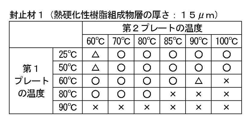
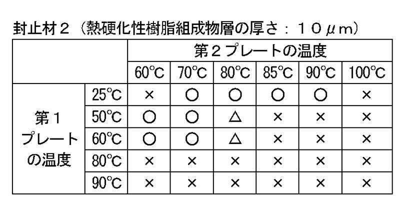
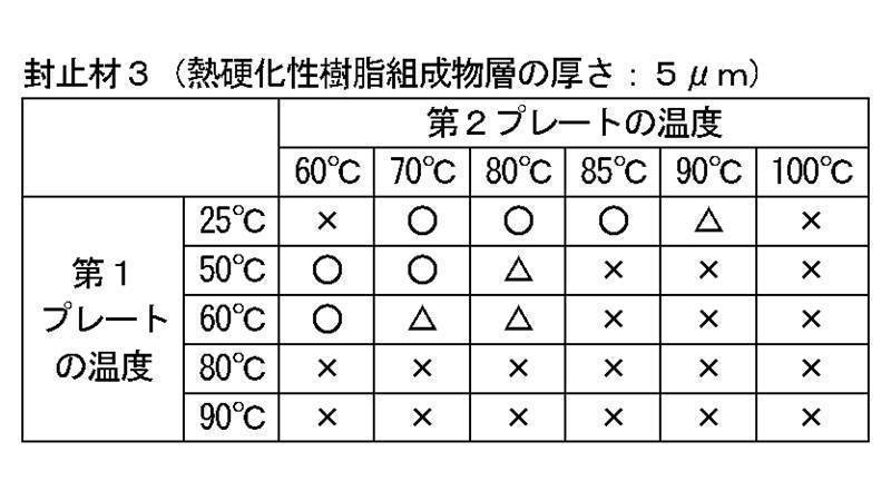
表1~3の結果から、ボイド発生のリスクは、封止材の熱硬化性樹脂組成物層の厚さが小さいほど大きくなることが分かる。これは厚さが小さくなるほど、プレートの温度の影響が大きくなり、熱硬化の進行により溶融性が低下して気泡が入り込み易くなったものと推測される。
さらに、ボイド発生のリスクは、第1プレートの温度が高くなるほど大きくなっていることが分かる。これは第1プレートの温度が高くなることで熱硬化性樹脂組成物層の熱硬化の進行により溶融性が低下して気泡が入り込み易くなったものと推測される。
さらに、ボイド発生のリスクは、第2プレートの温度が高くなるほど大きくなっていることが分かる。これは有機EL素子基板の熱で熱硬化性樹脂組成物層が溶融して積層されるが、その際に温度が高すぎると熱硬化の進行が進み溶融性が低下して気泡が張り込みやすくなったものと推定される。一方、温度が低すぎると、熱硬化樹脂組成物層の溶融性が低くなるかまたは溶融しないため、ボイド発生のリスクも上昇する。
さらに、ボイド発生のリスクは、第1プレートの温度が高くなるほど大きくなっていることが分かる。これは第1プレートの温度が高くなることで熱硬化性樹脂組成物層の熱硬化の進行により溶融性が低下して気泡が入り込み易くなったものと推測される。
さらに、ボイド発生のリスクは、第2プレートの温度が高くなるほど大きくなっていることが分かる。これは有機EL素子基板の熱で熱硬化性樹脂組成物層が溶融して積層されるが、その際に温度が高すぎると熱硬化の進行が進み溶融性が低下して気泡が張り込みやすくなったものと推定される。一方、温度が低すぎると、熱硬化樹脂組成物層の溶融性が低くなるかまたは溶融しないため、ボイド発生のリスクも上昇する。
<試験例1>
有機EL素子基板を使用して、以下のようにしてボイド発生を評価した。本評価は、熱硬化樹脂組成物層の積層時の硬化の進行に加え、有機EL素子基板表面への追従性の影響が反映された評価となると考えられる。
有機EL素子基板を使用して、以下のようにしてボイド発生を評価した。本評価は、熱硬化樹脂組成物層の積層時の硬化の進行に加え、有機EL素子基板表面への追従性の影響が反映された評価となると考えられる。
(1)有機EL素子基板の製造
有機ELパネル試作装置(平田機工社製)を使用し、酸化インジウムスズ(ITO)(厚さ1,500Å)(陽極)付パターン基板(テクノプリント社製)に、正孔注入層および正孔輸送層としてN,N’-ジ(1-ナフチル)-N,N’-ジフェニルベンジジン(α-NPD)(厚さ600Å)を蒸着し、発光層および電子輸送層としてトリス(8-キノリノラト)アルミニウム((Alq3)(厚さ650Å)を蒸着し、電子注入層としてフッ化リチウム(LiF)(厚さ5Å)を蒸着し、陰極としてアルミニウム(Al)(厚さ1,000Å)を蒸着して、有機EL素子基板を製造した。得られた有機EL素子基板の有機EL素子の厚さは、0.3755μmであった。
有機ELパネル試作装置(平田機工社製)を使用し、酸化インジウムスズ(ITO)(厚さ1,500Å)(陽極)付パターン基板(テクノプリント社製)に、正孔注入層および正孔輸送層としてN,N’-ジ(1-ナフチル)-N,N’-ジフェニルベンジジン(α-NPD)(厚さ600Å)を蒸着し、発光層および電子輸送層としてトリス(8-キノリノラト)アルミニウム((Alq3)(厚さ650Å)を蒸着し、電子注入層としてフッ化リチウム(LiF)(厚さ5Å)を蒸着し、陰極としてアルミニウム(Al)(厚さ1,000Å)を蒸着して、有機EL素子基板を製造した。得られた有機EL素子基板の有機EL素子の厚さは、0.3755μmであった。
(2)ボイド評価用積層サンプルの製造およびボイドの評価
上記のようにして得られた有機EL素子基板および参考例1で得られた封止材3を使用し、第1プレートおよび第2プレートの温度を表4に記載の温度に設定したこと以外は参考例1と同様にして、ボイド評価用積層サンプルの製造およびボイドの評価を行った。第1および第2プレートの温度、並びにボイドの評価結果を表4に示す。なお、表4において、「-」は、サンプルの製造およびボイドの評価を行っていないことを示す。
上記のようにして得られた有機EL素子基板および参考例1で得られた封止材3を使用し、第1プレートおよび第2プレートの温度を表4に記載の温度に設定したこと以外は参考例1と同様にして、ボイド評価用積層サンプルの製造およびボイドの評価を行った。第1および第2プレートの温度、並びにボイドの評価結果を表4に示す。なお、表4において、「-」は、サンプルの製造およびボイドの評価を行っていないことを示す。

表4の結果から分かるように、ボイドの発生は表3に示された傾向と一致する傾向となる。すなわち第2プレートの温度が高く、第1プレートの温度が低い場合に、ボイド発生が抑制される傾向となる。
本発明の方法は、有機ELデバイスの製造に有用である。
本願は、日本で出願された特願2017-101815号を基礎としており、その内容は本願明細書に全て包含される。
Claims (16)
- 基板上の有機EL素子が封止層で封止された封止体を製造する方法であって、
支持体上に厚さが20μm未満である熱硬化性樹脂組成物層が形成された封止材と、基板上に有機EL素子が形成された有機EL素子基板とを、熱硬化性樹脂組成物層が有機EL素子と接するように、二つのプレート間で加圧することによって積層する積層工程を含み、
封止材の支持体側に配置される第1プレートの温度が、有機EL素子基板の基板側に配置される第2プレートの温度よりも低いことを特徴とする方法。 - 熱硬化性樹脂組成物層が、積層工程で、有機EL素子基板の熱により溶融して積層される、請求項1に記載の方法。
- 第1プレートの温度が第2プレートの温度よりも5℃以上低い、請求項1または2に記載の方法。
- 第2プレートの温度が60℃以上100℃以下である、請求項1~3のいずれか一項に記載の方法。
- 第2プレートの温度が65℃以上95℃以下である、請求項1~3のいずれか一項に記載の方法。
- 第2プレートの温度が70℃以上90℃以下である、請求項1~3のいずれか一項に記載の方法。
- 第1プレートの温度が60℃未満である、請求項1~6のいずれか一項に記載の方法。
- 第1プレートの温度が50℃以下である、請求項1~6のいずれか一項に記載の方法。
- 積層が減圧下に行われる、請求項1~8のいずれか一項に記載の方法。
- 熱硬化性樹脂組成物層の厚さが18μm以下である、請求項1~9のいずれか一項に記載の方法。
- 熱硬化性樹脂組成物層の厚さが15μm以下である、請求項1~9のいずれか一項に記載の方法。
- 第1プレートおよび第2プレートが、それぞれ独立に金属プレートまたはセラミックプレートである、請求項1~11のいずれか一項に記載の方法。
- 支持体がガラス基板または防湿性フィルムである、請求項1~12のいずれか一項に記載の方法。
- 封止体が有機ELデバイスである、請求項1~13のいずれか一項に記載の方法。
- 積層工程の後、さらに熱硬化性樹脂層を熱硬化して封止層を形成する熱硬化工程を含む、請求項1~14のいずれか一項に記載の方法。
- 熱硬化工程が120℃以下の温度で行われる、請求項15に記載の方法。
Priority Applications (1)
| Application Number | Priority Date | Filing Date | Title |
|---|---|---|---|
| JP2019520251A JP7268596B2 (ja) | 2017-05-23 | 2018-05-22 | 封止体の製造方法 |
Applications Claiming Priority (2)
| Application Number | Priority Date | Filing Date | Title |
|---|---|---|---|
| JP2017-101815 | 2017-05-23 | ||
| JP2017101815 | 2017-05-23 |
Publications (1)
| Publication Number | Publication Date |
|---|---|
| WO2018216670A1 true WO2018216670A1 (ja) | 2018-11-29 |
Family
ID=64395673
Family Applications (1)
| Application Number | Title | Priority Date | Filing Date |
|---|---|---|---|
| PCT/JP2018/019565 Ceased WO2018216670A1 (ja) | 2017-05-23 | 2018-05-22 | 封止体の製造方法 |
Country Status (3)
| Country | Link |
|---|---|
| JP (1) | JP7268596B2 (ja) |
| TW (1) | TW201901995A (ja) |
| WO (1) | WO2018216670A1 (ja) |
Citations (6)
| Publication number | Priority date | Publication date | Assignee | Title |
|---|---|---|---|---|
| WO2010084938A1 (ja) * | 2009-01-23 | 2010-07-29 | 味の素株式会社 | 樹脂組成物 |
| JP2010211983A (ja) * | 2009-03-09 | 2010-09-24 | Seiko Epson Corp | 有機エレクトロルミネッセンス装置、その製造方法および電子機器 |
| JP2014154507A (ja) * | 2013-02-13 | 2014-08-25 | Mitsubishi Chemicals Corp | 有機エレクトロルミネッセンス発光装置、有機el表示装置及び有機el照明 |
| WO2016039237A1 (ja) * | 2014-09-08 | 2016-03-17 | コニカミノルタ株式会社 | 機能素子及び機能素子の製造方法 |
| JP2016520138A (ja) * | 2013-07-19 | 2016-07-11 | エルジー・ケム・リミテッド | 封止組成物 |
| JP2017016957A (ja) * | 2015-07-03 | 2017-01-19 | ランテクニカルサービス株式会社 | 基板接合体及びその製造方法 |
-
2018
- 2018-05-22 JP JP2019520251A patent/JP7268596B2/ja active Active
- 2018-05-22 TW TW107117323A patent/TW201901995A/zh unknown
- 2018-05-22 WO PCT/JP2018/019565 patent/WO2018216670A1/ja not_active Ceased
Patent Citations (6)
| Publication number | Priority date | Publication date | Assignee | Title |
|---|---|---|---|---|
| WO2010084938A1 (ja) * | 2009-01-23 | 2010-07-29 | 味の素株式会社 | 樹脂組成物 |
| JP2010211983A (ja) * | 2009-03-09 | 2010-09-24 | Seiko Epson Corp | 有機エレクトロルミネッセンス装置、その製造方法および電子機器 |
| JP2014154507A (ja) * | 2013-02-13 | 2014-08-25 | Mitsubishi Chemicals Corp | 有機エレクトロルミネッセンス発光装置、有機el表示装置及び有機el照明 |
| JP2016520138A (ja) * | 2013-07-19 | 2016-07-11 | エルジー・ケム・リミテッド | 封止組成物 |
| WO2016039237A1 (ja) * | 2014-09-08 | 2016-03-17 | コニカミノルタ株式会社 | 機能素子及び機能素子の製造方法 |
| JP2017016957A (ja) * | 2015-07-03 | 2017-01-19 | ランテクニカルサービス株式会社 | 基板接合体及びその製造方法 |
Also Published As
| Publication number | Publication date |
|---|---|
| JP7268596B2 (ja) | 2023-05-08 |
| TW201901995A (zh) | 2019-01-01 |
| JPWO2018216670A1 (ja) | 2020-03-26 |
Similar Documents
| Publication | Publication Date | Title |
|---|---|---|
| JP5601202B2 (ja) | 樹脂組成物 | |
| KR102244167B1 (ko) | 봉지용 수지 조성물 및 봉지용 시트 | |
| KR102121724B1 (ko) | 필름 | |
| JP7120017B2 (ja) | 封止用の樹脂組成物および封止用シート | |
| WO2015068787A1 (ja) | ハイドロタルサイトを含有する封止用樹脂組成物及び封止用シート | |
| CN108495894B (zh) | 密封用的热固性树脂组合物及密封用片材 | |
| WO2010084938A1 (ja) | 樹脂組成物 | |
| JP6992635B2 (ja) | 樹脂組成物 | |
| JP2011084667A (ja) | 樹脂組成物 | |
| JP6572887B2 (ja) | 封止体の製造方法 | |
| JP6428432B2 (ja) | 封止用シート、その製造方法および評価方法 | |
| JP7268596B2 (ja) | 封止体の製造方法 | |
| JP7552753B2 (ja) | 被着体の接着方法 | |
| JP2025111818A (ja) | 樹脂組成物および熱硬化型接着シート |
Legal Events
| Date | Code | Title | Description |
|---|---|---|---|
| 121 | Ep: the epo has been informed by wipo that ep was designated in this application |
Ref document number: 18806068 Country of ref document: EP Kind code of ref document: A1 |
|
| ENP | Entry into the national phase |
Ref document number: 2019520251 Country of ref document: JP Kind code of ref document: A |
|
| NENP | Non-entry into the national phase |
Ref country code: DE |
|
| 122 | Ep: pct application non-entry in european phase |
Ref document number: 18806068 Country of ref document: EP Kind code of ref document: A1 |