WO2018216154A1 - 内燃機関の制御方法及び制御装置 - Google Patents
内燃機関の制御方法及び制御装置 Download PDFInfo
- Publication number
- WO2018216154A1 WO2018216154A1 PCT/JP2017/019429 JP2017019429W WO2018216154A1 WO 2018216154 A1 WO2018216154 A1 WO 2018216154A1 JP 2017019429 W JP2017019429 W JP 2017019429W WO 2018216154 A1 WO2018216154 A1 WO 2018216154A1
- Authority
- WO
- WIPO (PCT)
- Prior art keywords
- combustion
- spark plug
- region
- stratified
- homogeneous
- Prior art date
Links
Images


Classifications
-
- F—MECHANICAL ENGINEERING; LIGHTING; HEATING; WEAPONS; BLASTING
- F02—COMBUSTION ENGINES; HOT-GAS OR COMBUSTION-PRODUCT ENGINE PLANTS
- F02D—CONTROLLING COMBUSTION ENGINES
- F02D41/00—Electrical control of supply of combustible mixture or its constituents
- F02D41/30—Controlling fuel injection
- F02D41/38—Controlling fuel injection of the high pressure type
- F02D41/40—Controlling fuel injection of the high pressure type with means for controlling injection timing or duration
- F02D41/402—Multiple injections
-
- F—MECHANICAL ENGINEERING; LIGHTING; HEATING; WEAPONS; BLASTING
- F02—COMBUSTION ENGINES; HOT-GAS OR COMBUSTION-PRODUCT ENGINE PLANTS
- F02D—CONTROLLING COMBUSTION ENGINES
- F02D37/00—Non-electrical conjoint control of two or more functions of engines, not otherwise provided for
- F02D37/02—Non-electrical conjoint control of two or more functions of engines, not otherwise provided for one of the functions being ignition
-
- F—MECHANICAL ENGINEERING; LIGHTING; HEATING; WEAPONS; BLASTING
- F02—COMBUSTION ENGINES; HOT-GAS OR COMBUSTION-PRODUCT ENGINE PLANTS
- F02D—CONTROLLING COMBUSTION ENGINES
- F02D41/00—Electrical control of supply of combustible mixture or its constituents
- F02D41/30—Controlling fuel injection
- F02D41/3011—Controlling fuel injection according to or using specific or several modes of combustion
- F02D41/3017—Controlling fuel injection according to or using specific or several modes of combustion characterised by the mode(s) being used
- F02D41/3023—Controlling fuel injection according to or using specific or several modes of combustion characterised by the mode(s) being used a mode being the stratified charge spark-ignited mode
- F02D41/3029—Controlling fuel injection according to or using specific or several modes of combustion characterised by the mode(s) being used a mode being the stratified charge spark-ignited mode further comprising a homogeneous charge spark-ignited mode
-
- F—MECHANICAL ENGINEERING; LIGHTING; HEATING; WEAPONS; BLASTING
- F02—COMBUSTION ENGINES; HOT-GAS OR COMBUSTION-PRODUCT ENGINE PLANTS
- F02P—IGNITION, OTHER THAN COMPRESSION IGNITION, FOR INTERNAL-COMBUSTION ENGINES; TESTING OF IGNITION TIMING IN COMPRESSION-IGNITION ENGINES
- F02P5/00—Advancing or retarding ignition; Control therefor
- F02P5/04—Advancing or retarding ignition; Control therefor automatically, as a function of the working conditions of the engine or vehicle or of the atmospheric conditions
- F02P5/145—Advancing or retarding ignition; Control therefor automatically, as a function of the working conditions of the engine or vehicle or of the atmospheric conditions using electrical means
-
- F—MECHANICAL ENGINEERING; LIGHTING; HEATING; WEAPONS; BLASTING
- F02—COMBUSTION ENGINES; HOT-GAS OR COMBUSTION-PRODUCT ENGINE PLANTS
- F02P—IGNITION, OTHER THAN COMPRESSION IGNITION, FOR INTERNAL-COMBUSTION ENGINES; TESTING OF IGNITION TIMING IN COMPRESSION-IGNITION ENGINES
- F02P9/00—Electric spark ignition control, not otherwise provided for
- F02P9/002—Control of spark intensity, intensifying, lengthening, suppression
-
- F—MECHANICAL ENGINEERING; LIGHTING; HEATING; WEAPONS; BLASTING
- F02—COMBUSTION ENGINES; HOT-GAS OR COMBUSTION-PRODUCT ENGINE PLANTS
- F02D—CONTROLLING COMBUSTION ENGINES
- F02D41/00—Electrical control of supply of combustible mixture or its constituents
- F02D41/30—Controlling fuel injection
- F02D41/38—Controlling fuel injection of the high pressure type
- F02D2041/389—Controlling fuel injection of the high pressure type for injecting directly into the cylinder
-
- F—MECHANICAL ENGINEERING; LIGHTING; HEATING; WEAPONS; BLASTING
- F02—COMBUSTION ENGINES; HOT-GAS OR COMBUSTION-PRODUCT ENGINE PLANTS
- F02P—IGNITION, OTHER THAN COMPRESSION IGNITION, FOR INTERNAL-COMBUSTION ENGINES; TESTING OF IGNITION TIMING IN COMPRESSION-IGNITION ENGINES
- F02P5/00—Advancing or retarding ignition; Control therefor
- F02P5/04—Advancing or retarding ignition; Control therefor automatically, as a function of the working conditions of the engine or vehicle or of the atmospheric conditions
- F02P5/045—Advancing or retarding ignition; Control therefor automatically, as a function of the working conditions of the engine or vehicle or of the atmospheric conditions combined with electronic control of other engine functions, e.g. fuel injection
-
- Y—GENERAL TAGGING OF NEW TECHNOLOGICAL DEVELOPMENTS; GENERAL TAGGING OF CROSS-SECTIONAL TECHNOLOGIES SPANNING OVER SEVERAL SECTIONS OF THE IPC; TECHNICAL SUBJECTS COVERED BY FORMER USPC CROSS-REFERENCE ART COLLECTIONS [XRACs] AND DIGESTS
- Y02—TECHNOLOGIES OR APPLICATIONS FOR MITIGATION OR ADAPTATION AGAINST CLIMATE CHANGE
- Y02T—CLIMATE CHANGE MITIGATION TECHNOLOGIES RELATED TO TRANSPORTATION
- Y02T10/00—Road transport of goods or passengers
- Y02T10/10—Internal combustion engine [ICE] based vehicles
- Y02T10/40—Engine management systems
Definitions
- the present invention forms a stratified mixture by performing fuel injection at least once during the period from the intake stroke to the first half of the compression stroke and the second half of the compression stroke.
- the present invention relates to the control of an internal combustion engine that performs spark ignition while the surrounding flow energy is increasing.
- JP 301999-303721 A1 discloses a control for making the discharge period longer than the discharge period during homogeneous combustion when performing stratified combustion during low load operation of the internal combustion engine.
- the control disclosed in the above document is for avoiding a situation where there is no combustible air-fuel mixture around the spark plug during the discharge period.
- the equivalent ratio around the spark plug is increased compared to the case of homogeneous combustion in which a homogeneous combustible mixture is formed in the entire combustion chamber and burned. That is, during stratified combustion, the air-fuel mixture around the spark plug is more likely to ignite than during homogeneous combustion. For this reason, the waveform of the discharge current for obtaining stable combustion during stratified combustion is different from the waveform of the discharge current during homogeneous combustion.
- an object of the present invention is to provide a method for controlling the waveform of the discharge current so as to be suitable for stratified combustion during stratified combustion.
- a part of the low / medium rotational speed / low / medium load region of the internal combustion engine is a lean combustion region, and in an operation region where the load in the lean combustion region is relatively low, During the first half, at least one fuel injection is performed to form a homogeneous mixture in the combustion chamber to perform homogeneous combustion, and in the operation region where the load in the lean combustion region is relatively high, the intake stroke to the compression stroke.
- a control method for an internal combustion engine that performs stratified combustion by forming a stratified mixture in a combustion chamber by performing fuel injection at least once during the first half and during the second half of the compression stroke.
- the ignition energy supplied to the spark plug when performing stratified combustion is controlled to be smaller than the ignition energy supplied to the spark plug when performing homogeneous combustion.
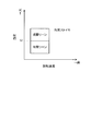
- FIG. 1 is an explanatory diagram of the overall configuration of the internal combustion engine system.
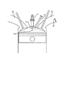
- FIG. 2 is an explanatory diagram of fluid application in the vicinity of the plug.
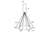
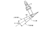
- FIG. 3 is a view showing an injection form of the fuel injection valve.
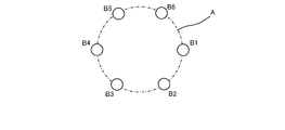
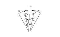
- FIG. 4 is a diagram for explaining the spray beam.
- FIG. 5 is a diagram showing the arrangement of the spark plug and the fuel injection valve.
- FIG. 6 is a diagram showing the relationship between the discharge region and the spray beam.
- FIG. 7 is a diagram for explaining the contracted flow.
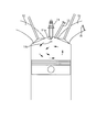
- FIG. 8 is an explanatory diagram of tumble flow generated in the cylinder.
- FIG. 9 is an explanatory diagram of tumble flow during the compression stroke.
- FIG. 10 is a diagram showing a change in turbulence intensity around the spark plug.
- FIG. 10 is a diagram showing a change in turbulence intensity around the spark plug.
- FIG. 11 is an explanatory diagram of the plug discharge channel in the vicinity of the spark plug.
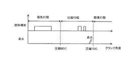
- FIG. 12A is a diagram illustrating a relationship between fuel injection timing and ignition timing.
- FIG. 12B is a diagram illustrating a relationship between the fuel injection timing and the ignition timing.
- FIG. 13 is a combustion form map.
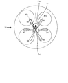
- FIG. 14 is a diagram illustrating an example of a variable compression ratio mechanism.
- FIG. 15 is a chart of the gas flow rate of the discharge gap and the air-fuel ratio of the discharge gap during homogeneous lean combustion.
- FIG. 16 is a chart showing the relationship between the elapsed time from the ignition timing and the secondary current during homogeneous lean combustion.
- FIG. 12A is a diagram illustrating a relationship between fuel injection timing and ignition timing.
- FIG. 12B is a diagram illustrating a relationship between the fuel injection timing and the ignition timing.
- FIG. 13 is a combustion form map.
- FIG. 14 is a diagram illustrating an example of a variable compression
- FIG. 17 is a chart of the gas flow rate of the discharge gap and the air-fuel ratio of the discharge gap during stratified lean combustion.
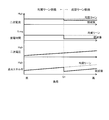
- FIG. 18 is a chart showing the relationship between the elapsed time from the ignition timing and the secondary current during stratified lean combustion.
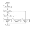
- FIG. 19 is a flowchart showing a control routine stored in the controller.
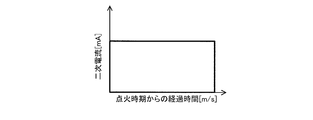
- FIG. 20 is a diagram showing the relationship between the secondary current, discharge time, secondary voltage, ignition energy, and load of the internal combustion engine in the lean combustion region.
- FIG. 21 is a diagram showing the relationship among the air-fuel ratio, mechanical compression ratio, and fuel consumption of the entire combustion chamber and the load on the internal combustion engine in the lean combustion region.
- FIG. 1 is an explanatory diagram of the overall configuration of the internal combustion engine system.
- the internal combustion engine 10 is connected to an intake passage 51.
- the internal combustion engine 10 is connected to the exhaust passage 52.
- a tumble control valve 16 is provided in the intake passage 51.
- the tumble control valve 16 generates a tumble flow in the cylinder by closing part of the cross section of the intake passage 51.
- a collector tank 46 is provided in the intake passage 51.
- An EGR passage 53 b is also connected to the collector tank 46.
- An air flow meter 33 is provided in the intake passage 51.
- the controller 50 connected to the air flow meter 33 acquires the intake air amount in the intake passage 51 from the air flow meter 33.
- An intake air temperature sensor 34 is provided in the intake passage 51.
- the controller 50 connected to the intake air temperature sensor 34 acquires the temperature of the air passing through the intake passage 51 from the intake air temperature sensor 34.
- an electronic control throttle 41 is provided in the intake passage 51, and the throttle opening is controlled by the controller 50.
- the exhaust passage 52 is provided with exhaust catalysts 44 and 45 for exhaust purification.
- a three-way catalyst or the like is used for the exhaust catalysts 44 and 45.
- the exhaust passage 52 branches into an EGR passage 53 connected to the collector tank 46 in the middle thereof.
- an EGR cooler 43 is provided in the EGR passage 53.
- the EGR passage 53 is provided with an EGR valve 42.
- the EGR valve 42 is connected to the controller 50. Then, the opening degree of the EGR valve 42 is controlled by the controller 50 in accordance with the operating conditions of the internal combustion engine 10.
- the internal combustion engine 10 includes a spark plug 11, a fuel injection valve 12, an intake side variable valve mechanism 13, an exhaust side variable valve mechanism 14, and a fuel injection pump 15.
- the fuel injection valve 12 is a direct injection valve and is provided in the vicinity of the spark plug 11.
- the spark plug 11 is driven by the driving device 17 to perform spark ignition in the combustion chamber of the internal combustion engine 10.
- the spark plug 11 is connected to the controller 50, and the controller 50 as a control unit controls the ignition timing.
- the “ignition timing” in the present embodiment refers to the timing at which spark ignition is started.
- the spark plug 11 also operates as a flow rate sensor 23 that detects the gas flow rate between the discharge gaps.
- the driving device 17 causes the spark plug 11 to generate a discharge voltage in response to the ignition signal from the controller 50.
- the driving device 17 applies a voltage in the same direction as the discharge voltage (hereinafter also referred to as a superimposed voltage) between the electrodes of the spark plug 11 during the discharge period. It also has a circuit for doing this. Since the configuration for applying the superimposed voltage is known (for example, JP2016-53312A1), detailed description thereof is omitted.
- the discharge period can be arbitrarily controlled by controlling the overlap voltage.
- the fuel injection valve 12 directly injects fuel into the combustion chamber of the internal combustion engine 10.
- the fuel injection valve 12 is connected to the controller 50, and the controller 50 as a control unit controls the fuel injection timing.
- so-called multistage injection is performed in which fuel injection is performed a plurality of times including the intake stroke.
- the fuel injection pump 15 supplies pressurized fuel to a fuel supply pipe connected to the fuel injection valve 12.
- the intake side variable valve mechanism 13 changes the opening / closing timing of the intake valve.
- the exhaust side variable valve mechanism 14 changes the opening / closing timing of the exhaust valve.
- the intake side variable valve mechanism 13 and the exhaust side variable valve mechanism 14 are connected to a controller 50.
- the controller 50 controls the opening / closing timing.
- the intake side variable valve mechanism 13 and the exhaust side variable valve mechanism 14 are shown here, you may have any one.
- the internal combustion engine 10 is provided with a crank angle sensor, an in-cylinder pressure sensor, and an accelerator opening sensor (not shown).
- the crank angle sensor detects a crank angle in the internal combustion engine 10.
- the crank angle sensor is connected to the controller 50 and sends the crank angle of the internal combustion engine 10 to the controller 50.
- the cylinder pressure sensor detects the pressure of the combustion chamber in the internal combustion engine 10.
- the in-cylinder pressure sensor is connected to the controller 50. Then, the pressure of the combustion chamber in the internal combustion engine 10 is sent to the controller 50.
- Accelerator opening sensor detects the amount of accelerator pedal depression by the driver.
- the internal combustion engine 10 may include a knock sensor 21 and a fuel pressure sensor 24.
- the controller 50 reads outputs from the above-described various sensors and other sensors (not shown), and controls ignition timing, valve timing, air-fuel ratio, and the like based on these outputs.
- the internal combustion engine 10 includes a variable compression ratio mechanism that changes the mechanical compression ratio, and the controller 50 also controls the variable compression ratio mechanism. Details of the variable compression ratio mechanism will be described later.
- FIG. 2 is a diagram for explaining the positional relationship between the spark plug 11 and the fuel injection valve 12.
- the fuel injection valve 12 is a direct injection valve and is provided in the vicinity of the spark plug 11. Therefore, a part of the injected fuel passes through the vicinity of the discharge gap, so that the flow can be provided in the vicinity of the spark plug. The provision of flow will be described later.
- FIG. 3 shows the form of fuel spray injected from the fuel injection valve 12.
- 4 is a view of the plane including the circle A in FIG. 3 as viewed from the direction of arrow IV in FIG.
- each spray beam has a conical shape in which the spray cross section becomes wider as the distance from the nozzle holes increases. Further, when the spray beams B1-B6 are cut along a plane including the circle A, the cross sections are arranged in an annular shape at equal intervals as shown in FIG.
- FIG. 5 is a view showing the positional relationship between the spray beam B1-B6 and the spark plug 11. As shown in FIG. The fuel injection valve 12 is disposed on a one-dot chain line C that is a bisector of an angle formed by the central axis B2c of the spray beam B2 and the central axis B3c of the spray beam B3.
- FIG. 6 is a diagram showing a positional relationship between the spark plug 11 and the spray beam B3 when FIG. 5 is viewed from the direction of the arrow VI.
- the discharge region sandwiched between the center electrode 11a and the outer electrode 11b is disposed within a range sandwiched between the outer edge on the upper side in the drawing and the outer edge on the lower side in the drawing of the spray beam B3.
- the positional relationship between the spark plug 11 and the spray beam B2 is the same as that in FIG. 6, and the discharge region is below the outer edge on the upper side of the spray beam B2. It arrange
- the discharge region is within a range sandwiched between a plane including the upper outer edge of the spray beam B2 and the upper outer edge of the spray beam B3 and a plane including the lower outer edge of the spray beam B2 and the lower outer edge of the spray beam B3.
- the spark plug 11 is disposed so as to be disposed.
- FIG. 7 is a diagram for explaining the effect when the spray beam B1-B6 and the spark plug 11 are in the positional relationship shown in FIGS.
- the fuel injected from the fuel injection valve 12 is divided into droplets and sprayed, and moves forward while taking in the surrounding air as indicated by the thick arrows in the figure. Thereby, the turbulence of the airflow occurs around the spray.
- the fluid when there is an object (including a fluid) around the fluid, the fluid is attracted to the object by the so-called Coanda effect and flows along the object. That is, a so-called contracted flow is generated in which the spray beam B2 and the spray beam B3 are attracted as shown by the thin line arrows in FIG. As a result, a very strong turbulence occurs between the spray beam B2 and the spray beam B3, so that the turbulence intensity around the spark plug 11 increases.
- FIG. 8 is an explanatory diagram of the tumble flow that occurs in the cylinder.
- FIG. 9 is a diagram for explaining the attenuation of the tumble flow.
- an intake passage 51 an exhaust passage 52, a spark plug 11, a fuel injection valve 12, and a tumble control valve 16 are shown. Further, a center electrode 11a and an outer electrode 11b of the spark plug 11 are shown.
- the tumble flow in the cylinder in the suction stroke is indicated by an arrow.
- the tumble flow in the cylinder during the compression stroke is indicated by arrows.
- FIG. 10 is a timing chart showing changes in the turbulence intensity around the spark plug 11 when fuel injection is performed in the latter half of the compression stroke.
- the horizontal axis in FIG. 10 indicates the crank angle, and the vertical axis indicates the turbulence intensity around the spark plug 11.
- the broken line in the figure shows the change in turbulence intensity when fuel injection is not performed in the latter half of the compression stroke.
- the turbulence intensity around the spark plug 11 also decreases accordingly.
- the turbulence intensity increases for a predetermined period after fuel injection.
- the plug discharge channel CN is easily extended.
- the timing C1 at which the turbulence intensity reaches a peak is suitable as the ignition timing.
- the timing C2 earlier than the timing C1 is suitable for the ignition timing in the case of homogeneous lean combustion.
- FIG. 11 is an explanatory diagram of the plug discharge channel CN.
- FIG. 11 shows the center electrode 11a and the outer electrode 11b of the spark plug 11, and the extended plug discharge channel CN.
- the fuel injection valve 12 is omitted. Note that the tip of the fuel injection valve 12 does not necessarily have to face the ignition plug 11 as long as the flow is applied around the ignition plug so that the plug discharge channel CN extends sufficiently.
- an embodiment in which injected fuel is reflected in the combustion chamber and flows around the spark plug may be used.
- the plug discharge channel CN is generated so as to extend between the center electrode 11a and the outer electrode 11b substantially linearly.
- spark ignition is performed in a state where the flow around the spark plug 11 is strengthened by the fuel injection by the fuel injection valve 12.
- the plug discharge channel CN between the center electrode 11a and the outer electrode 11b extends as shown in FIG.
- 12A and 12B are diagrams showing examples of fuel injection patterns for extending the plug discharge channel CN. 12A and 12B, 90% or more of the total injection amount is injected in the intake stroke. The remaining fuel may be divided and injected twice in the latter half of the compression stroke (FIG. 12A), or may be injected once (FIG. 12B). The total injection amount here is the amount of fuel injected per cycle.
- the amount of fuel that is injected in the latter half of the compression stroke to form a combustible mixture around the spark plug 11 is 10% or less of the total injection amount.
- the combustible air-fuel mixture formed around the spark plug 11 is only a part of the entire burning chamber.
- Such stratified combustion may be referred to as “weakly stratified combustion” in order to distinguish it from stratified combustion in which more fuel is injected in the latter half of the compression stroke.
- the controller 50 switches the combustion mode according to the operating state of the internal combustion engine 10.
- the operating state referred to here is the rotational speed and load of the internal combustion engine 10.
- the rotational speed can be calculated by a known method based on the detection value of the crank angle sensor.
- the load can be calculated by a known method based on the detection value of the accelerator opening sensor.
- FIG. 13 is a map showing combustion modes executed in each operation state.
- the vertical axis represents the load
- the horizontal axis represents the rotational speed.
- a part of the low / medium rotation / low / medium load region is the lean combustion region, and the other region is the homogeneous stoichiometric combustion region.
- the lean combustion region is further divided, with the load Q1 as a boundary, the region with a relatively high load is a stratified lean combustion region, and the region with a relatively low load is a homogeneous lean combustion region.
- stratified lean combustion refers to the above-described stratified combustion.
- Homogeneous stoichiometric combustion is combustion performed by forming a stoichiometric air-fuel mixture in the entire combustion chamber.
- the load Q1 is set according to the specification of the internal combustion engine 10 to which this embodiment is applied.
- the controller 50 basically controls the excess air ratio ⁇ of the entire combustion chamber to 2.
- the controller 50 may correct the excess air ratio ⁇ to be richer than 2 in order to ensure ignitability in accordance with an increase in load.
- the air / fuel ratio A / F may be used instead of the excess air ratio ⁇ .
- the excess air ratio ⁇ 2 is expressed as air-fuel ratio A / F ⁇ 30.
- the controller 50 reduces the mechanical compression ratio in order to suppress the occurrence of knocking as the load of the internal combustion engine 10 increases.
- the controller 50 controls the mechanical compression ratio to be higher during stratified lean combustion than when the homogeneous lean combustion is performed under the same operating conditions. This is because stratified lean combustion has a higher combustion rate and is less likely to cause knocking than homogeneous lean combustion.
- variable compression ratio mechanism will be described.
- a known variable compression ratio mechanism may be used.
- an example of a known variable compression ratio mechanism will be described.
- FIG. 14 shows a variable compression ratio mechanism in which the top dead center position of the piston 25 can be variably controlled by connecting the piston 25 and the crankshaft 30 with a plurality of links.
- the piston 25 is connected to the crankshaft 30 via an upper link 26 and a lower link 27.
- One end of the upper link 26 is rotatably connected to the piston 25 and the other end is rotatably connected to the lower link 27.
- the lower link 27 is rotatably connected to the crankpin 30 ⁇ / b> A of the crankshaft 30 at a portion different from the connecting portion with the upper link 26.
- one end of a control link 28 is rotatably connected to the lower link 27. The other end of the control link 28 is connected to a position shifted from the rotation center of the control shaft 29.
- the mechanical compression ratio can be changed by rotating the control shaft 29 with an actuator (not shown) or the like.
- the control shaft 29 is rotated by a predetermined angle in the counterclockwise direction in the figure
- the lower link 27 rotates in the counterclockwise direction in the figure about the crank pin 30A via the control link 28.
- the top dead center position of the piston 25 rises and the mechanical compression ratio rises.
- the control shaft 29 is rotated by a predetermined angle in the clockwise direction in the drawing
- the lower link 27 rotates in the clockwise direction in the drawing around the crank pin 30A via the control link 28.
- the top dead center position of the piston 25 is lowered, and the mechanical compression ratio is lowered.
- FIG. 15 is a chart showing changes in the gas flow rate of the discharge gap and the air-fuel ratio A / F of the discharge gap during homogeneous lean combustion.
- the horizontal axis in FIG. 15 is the crank angle [deg], and shows the state after the timing C2 in FIG.
- FIG. 16 is a chart showing the relationship between the elapsed time from the ignition timing and the secondary current flowing through the spark plug 11 during homogeneous lean combustion.
- FIG. 17 is a chart showing changes in the gas flow rate of the discharge gap and the air-fuel ratio A / F of the discharge gap during homogeneous lean combustion.
- the horizontal axis in FIG. 17 is the crank angle [deg], and shows the state after the timing C1 in FIG.
- FIG. 18 is a chart showing the relationship between the elapsed time from the ignition timing and the secondary current flowing through the spark plug 11 during stratified lean combustion.
- the broken line in a figure is a chart at the time of the homogeneous lean combustion of FIG.
- FIG. 15 and FIG. 17 have the same meaning as the turbulence intensity described in FIG.
- the gas velocity in the discharge gap decreases as the crank angle advances. Further, during the homogeneous lean combustion, the excess air ratio ⁇ of the entire combustion chamber is controlled to 2, that is, the air-fuel ratio A / F is controlled to about 30, so that naturally the air-fuel ratio A / F of the discharge gap is about 30.
- the fuel injection in the latter half of the compression stroke makes the air / fuel ratio A / F of the discharge gap at the ignition timing richer than that during homogeneous lean combustion.
- the air-fuel ratio A / F of the discharge gap gradually returns to 30.
- the A / F of the discharge gap is substantially 30 compared to stoichiometric, so the mixture in the discharge gap is less likely to ignite than during stratified lean combustion. Also, the combustion rate is slower during homogeneous lean combustion than during stratified lean combustion. Therefore, during homogeneous lean combustion, it is necessary to keep a relatively large secondary current flowing in order to obtain stable combustion.
- the mixture in the discharge gap is more easily ignited than at the time of homogeneous lean combustion, so that stable combustion can be obtained even at a secondary current lower than that at the time of homogeneous lean combustion. Further, as described above, since the air-fuel mixture in the discharge gap is more easily ignited than in the homogeneous lean combustion, the discharge time can be shortened in the stratified lean combustion compared with the homogeneous lean combustion.
- the ignition energy consumed per cycle can be made smaller than that during homogeneous lean combustion by reducing the secondary current as described above or shortening the discharge time.
- the discharge waveform suitable for stratified lean combustion differs from the discharge waveform suitable for homogeneous lean combustion.
- the discharge waveform refers to the history of the secondary current shown in FIGS.
- the controller 50 ensures that a constant secondary current flows during homogeneous lean combustion, a relatively large secondary current flows during ignition timing, and then the secondary current decreases during stratified lean combustion.
- the drive device 17 is controlled respectively.
- the waveform of the secondary current shown in FIG. 18 is merely an example, and other waveforms may be used as long as the ignition energy is smaller than that during homogeneous lean combustion.
- the waveform may be such that the secondary current at the ignition timing is relatively high and the secondary current thereafter decreases in order to generate the initial flame kernel more reliably.
- the secondary current may decrease in proportion to the elapsed time, or may decrease stepwise at predetermined time intervals.
- the waveform of the secondary current during stratified lean combustion can take various forms.
- FIG. 19 is a diagram specifically showing the above-described control content as a control routine.
- the control routine is programmed in the controller 50.
- step S10 the controller 50 reads the operating state. Specifically, the rotational speed and load of the internal combustion engine 10 are read.
- step S20 the controller 50 determines whether or not the current operation region is a lean combustion region, using the operation state read in step S10 and the map of FIG.
- the controller 50 executes the process of step S30 if it is a lean combustion region, and executes the process of step S60 if it is a homogeneous stoichiometric combustion region.
- step S30 the controller 50 determines whether or not the current operation region is a stratified lean combustion region.
- the controller 50 executes the process of step S40 if it is a stratified lean combustion region, and executes the process of step S50 if it is a homogeneous lean combustion region.
- step S40 the controller 50 controls the drive unit 17 so that the discharge waveform for the stratified lean combustion described above is obtained.
- step S50 the controller 50 controls the driving device 17 so as to obtain the above-described discharge waveform for homogeneous lean combustion.
- step S60 the controller 50 controls the driving device 17 so as to obtain a discharge waveform for homogeneous stoichiometric combustion.
- the discharge waveform for homogeneous stoichiometric combustion is basically the same as the discharge waveform for homogeneous lean combustion, but the secondary current is smaller and the discharge time is shorter than the discharge waveform for homogeneous lean combustion.
- FIG. 20 is a diagram showing the relationship between the secondary current, discharge time, secondary voltage, ignition energy, and load of the internal combustion engine 10 in the lean combustion region.
- the load Q1 in the figure is the same as the load Q1 in FIG. In the figure, for comparison purposes, a broken line indicates a value when it is assumed that homogeneous lean combustion is performed in the entire lean combustion region, that is, even in a relatively high load region.
- the secondary current in FIG. 20 is a current value at the ignition timing.
- the secondary current during stratified lean combustion is lower than the secondary current when performing homogeneous lean combustion in the region.
- the discharge time for stratified lean combustion is shorter than the discharge time for homogeneous lean combustion in the region.
- the secondary voltage increases as the load increases over the entire lean combustion region, and the ignition energy increases accordingly.
- the ignition energy is smaller than that in the case of performing the homogeneous lean combustion in the region.
- FIG. 21 is a diagram showing the relationship among the air-fuel ratio, mechanical compression ratio, and fuel consumption of the entire combustion chamber and the load on the internal combustion engine 10 in the lean combustion region.
- the load Q1 in the figure is the same as the load Q1 in FIG.
- a broken line indicates a value when it is assumed that homogeneous lean combustion is performed in the entire lean combustion region, that is, even in a relatively high load region.
- the controller 50 makes the air-fuel ratio of the entire combustion chamber richer than 30 in order to ensure ignitability as the load increases.
- ignition becomes easy because the equivalent ratio around the spark plug 11 is increased by fuel injection in the latter half of the compression stroke.
- the air-fuel ratio of the entire combustion chamber can be made lean compared to the case of performing homogeneous lean combustion in the same region.
- the controller 50 lowers the mechanical compression ratio in order to suppress the occurrence of knocking as the load increases.
- the fuel ratio in the vicinity of the spark plug 11 is increased by the fuel injection in the latter half of the compression stroke, so that the flame propagation becomes faster, thereby making it difficult for knocking to occur.
- the mechanical compression ratio can be made higher than in the case of performing homogeneous lean combustion in the same region.
- the air-fuel ratio of the entire combustion chamber becomes leaner and the mechanical compression ratio is higher than when homogeneous lean combustion is performed in the same region. Can be high. As a result, the fuel consumption in the relatively high load region is improved compared to the case where homogeneous lean combustion is performed in the same region.
- the controller 50 is at least 1 between the intake stroke and the first half of the compression stroke in the operation region where the load of the internal combustion engine 10 is relatively low in the lean combustion region.
- the controller 50 performs fuel injection at least once during the period from the intake stroke to the first half of the compression stroke and the second half of the compression stroke in the operation region where the load of the internal combustion engine 10 is relatively high in the lean combustion region.
- a stratified mixture is formed in the combustion chamber and stratified lean combustion is performed.
- the controller 50 controls the ignition energy supplied to the spark plug 11 when performing stratified lean combustion to be smaller than the ignition energy supplied to the spark plug 11 when performing homogeneous lean combustion.
- the controller 50 controls the excess air ratio of the entire combustion chamber to 2 in both cases of stratified lean combustion and homogeneous lean combustion.
- the controller 50 makes the ignition energy during the stratified lean combustion smaller than the ignition energy during the homogeneous lean combustion by making the discharge time of the spark plug 11 during the stratified lean combustion shorter than that during the homogeneous lean combustion. To do.
- the controller 50 reduces the secondary current (discharge current) at the time of stratified lean combustion to the secondary current (discharge current) at the time of homogeneous lean combustion so that the ignition energy at the time of stratified lean is homogeneous. Control to be smaller than the ignition energy during lean combustion.
Landscapes
- Engineering & Computer Science (AREA)
- Chemical & Material Sciences (AREA)
- Combustion & Propulsion (AREA)
- Mechanical Engineering (AREA)
- General Engineering & Computer Science (AREA)
- Electrical Control Of Air Or Fuel Supplied To Internal-Combustion Engine (AREA)
- Combustion Methods Of Internal-Combustion Engines (AREA)
- Ignition Installations For Internal Combustion Engines (AREA)
- Electrical Control Of Ignition Timing (AREA)
- Combined Controls Of Internal Combustion Engines (AREA)
Abstract
Description
Claims (5)
- 内燃機関の低中回転速度・低中負荷領域の一部をリーン燃焼領域とし、
前記リーン燃焼領域内の負荷が相対的に低い運転領域では、吸気行程から圧縮行程前半までの間に少なくとも1回の燃料噴射を行うことで燃焼室内に均質混合気を形成して均質燃焼を行い、
前記リーン燃焼領域内の負荷が相対的に高い運転領域では、吸気行程から圧縮行程前半までの間と、圧縮行程後半とに少なくとも1回ずつの燃料噴射を行うことで燃焼室内に成層混合気を形成して成層燃焼を行う内燃機関の制御方法において、
前記成層燃焼を行う際に点火プラグに供給する点火エネルギを、前記均質燃焼を行う際に点火プラグに供給する点火エネルギより小さく制御する、
内燃機関の制御方法。 - 請求項1に記載の内燃機関の制御方法において、
前記成層燃焼時と前記均質燃焼時のいずれの場合も、燃焼室全体の空気過剰率が2になるよう制御する、
内燃機関の制御方法。 - 請求項1または2に記載の内燃機関の制御方法において、
前記成層燃焼時の前記点火プラグの放電時間を、前記均質燃焼時の前記点火プラグの放電時間より短くすることにより、前記成層燃焼を行う際に点火プラグに供給する点火エネルギを、前記均質燃焼を行う際に点火プラグに供給する点火エネルギより小さく制御する、
内燃機関の制御方法。 - 請求項1から3のいずれかに記載の内燃機関の制御方法において、
前記成層燃焼時の前記点火プラグの放電電流を、前記均質燃焼時の前記点火プラグの放電電流より小さくすることにより、前記成層燃焼を行う際に点火プラグに供給する点火エネルギを、前記均質燃焼を行う際に点火プラグに供給する点火エネルギより小さく制御する、
内燃機関の制御方法。 - 燃焼室内に直接燃料を噴射する燃料噴射弁と、
前記燃焼室内に形成された混合気に火花点火する点火プラグと、
前記点火プラグを駆動する駆動装置と、
前記燃料噴射弁と前記駆動装置とを制御する制御部と、
を備える内燃機関の制御装置において、
前記制御部は、
内燃機関の低中回転速度・低中負荷領域の一部をリーン燃焼領域とし、前記リーン燃焼領域内の負荷が相対的に低い運転領域では、吸気行程から圧縮行程前半までの間に少なくとも1回の燃料噴射を行うことで前記燃焼室内に均質混合気を形成して均質燃焼を行い、
前記リーン燃焼領域内の負荷が相対的に高い運転領域では、吸気行程から圧縮行程前半までの間と、圧縮行程後半とに少なくとも1回ずつの燃料噴射を行うことで燃焼室内に成層混合気を形成して成層燃焼を行い、
前記成層燃焼を行う際に点火プラグに供給する点火エネルギを、前記均質燃焼を行う際に点火プラグに供給する点火エネルギより小さく制御する、
内燃機関の制御装置。
Priority Applications (5)
| Application Number | Priority Date | Filing Date | Title |
|---|---|---|---|
| CN201780090710.XA CN110651118B (zh) | 2017-05-24 | 2017-05-24 | 内燃机的控制方法以及控制装置 |
| US16/615,228 US11248555B2 (en) | 2017-05-24 | 2017-05-24 | Control method and control device for internal combustion engine |
| PCT/JP2017/019429 WO2018216154A1 (ja) | 2017-05-24 | 2017-05-24 | 内燃機関の制御方法及び制御装置 |
| EP17911342.8A EP3633183A4 (en) | 2017-05-24 | 2017-05-24 | METHOD AND DEVICE FOR CONTROLLING AN INTERNAL COMBUSTION ENGINE |
| JP2019519893A JP6835217B2 (ja) | 2017-05-24 | 2017-05-24 | 内燃機関の制御方法及び制御装置 |
Applications Claiming Priority (1)
| Application Number | Priority Date | Filing Date | Title |
|---|---|---|---|
| PCT/JP2017/019429 WO2018216154A1 (ja) | 2017-05-24 | 2017-05-24 | 内燃機関の制御方法及び制御装置 |
Publications (1)
| Publication Number | Publication Date |
|---|---|
| WO2018216154A1 true WO2018216154A1 (ja) | 2018-11-29 |
Family
ID=64396385
Family Applications (1)
| Application Number | Title | Priority Date | Filing Date |
|---|---|---|---|
| PCT/JP2017/019429 WO2018216154A1 (ja) | 2017-05-24 | 2017-05-24 | 内燃機関の制御方法及び制御装置 |
Country Status (5)
| Country | Link |
|---|---|
| US (1) | US11248555B2 (ja) |
| EP (1) | EP3633183A4 (ja) |
| JP (1) | JP6835217B2 (ja) |
| CN (1) | CN110651118B (ja) |
| WO (1) | WO2018216154A1 (ja) |
Cited By (2)
| Publication number | Priority date | Publication date | Assignee | Title |
|---|---|---|---|---|
| JPWO2018216153A1 (ja) * | 2017-05-24 | 2020-04-30 | 日産自動車株式会社 | 内燃機関の制御方法及び制御装置 |
| JP7448461B2 (ja) | 2020-11-06 | 2024-03-12 | 日産自動車株式会社 | 火花点火式多気筒内燃機関の制御方法および制御装置 |
Citations (6)
| Publication number | Priority date | Publication date | Assignee | Title |
|---|---|---|---|---|
| JPH11303721A (ja) | 1998-04-24 | 1999-11-02 | Nippon Soken Inc | 内燃機関の点火装置 |
| JP2001153015A (ja) * | 1999-11-29 | 2001-06-05 | Mitsubishi Motors Corp | 火花点火式層状燃焼内燃機関の点火制御装置 |
| JP2004245171A (ja) * | 2003-02-17 | 2004-09-02 | Toyota Motor Corp | 混合気を圧縮自着火させる自着火運転が可能な内燃機関 |
| JP2006046276A (ja) * | 2004-08-09 | 2006-02-16 | Nissan Motor Co Ltd | 直噴火花点火式内燃機関の点火制御装置 |
| JP2015200254A (ja) * | 2014-04-10 | 2015-11-12 | 株式会社デンソー | 点火装置 |
| JP2016053312A (ja) | 2014-09-03 | 2016-04-14 | 日産自動車株式会社 | 内燃機関の点火装置および点火方法 |
Family Cites Families (32)
| Publication number | Priority date | Publication date | Assignee | Title |
|---|---|---|---|---|
| JPH0514565U (ja) * | 1991-08-01 | 1993-02-26 | 日産デイーゼル工業株式会社 | 筒内噴射式内燃機関の点火制御装置 |
| JPH0666236A (ja) * | 1992-08-20 | 1994-03-08 | Honda Motor Co Ltd | プラズマジェット点火装置 |
| EP1471240A2 (en) * | 1997-05-21 | 2004-10-27 | Nissan Motor Co., Ltd. | Transient control between two spark-ignited combustion states in engine |
| US6026792A (en) * | 1997-06-20 | 2000-02-22 | Outboard Marine Corporation | Method of operating a fuel injected engine |
| JP3578597B2 (ja) * | 1997-06-30 | 2004-10-20 | 株式会社日立ユニシアオートモティブ | 直噴火花点火式内燃機関の制御装置 |
| DE19730908C2 (de) * | 1997-07-18 | 2002-11-28 | Daimler Chrysler Ag | Verfahren zum Betrieb einer direkteinspritzenden Otto-Brennkraftmaschine |
| JP3815006B2 (ja) * | 1997-12-09 | 2006-08-30 | 日産自動車株式会社 | 内燃機関の制御装置 |
| WO1999067514A1 (fr) * | 1998-06-22 | 1999-12-29 | Hitachi, Ltd. | Moteur a combustion interne de type a injection dans le cylindre |
| US6116208A (en) * | 1998-09-29 | 2000-09-12 | Mazda Motor Corporation | Control system for a direct injection-spark ignition engine |
| JP3651304B2 (ja) | 1999-03-26 | 2005-05-25 | 日産自動車株式会社 | 内燃機関の点火装置 |
| JP3731403B2 (ja) * | 1999-09-09 | 2006-01-05 | 日産自動車株式会社 | 直噴火花点火式内燃機関の制御装置 |
| JP4253426B2 (ja) | 1999-09-14 | 2009-04-15 | 日産自動車株式会社 | 圧縮自己着火式ガソリン機関 |
| JP3552609B2 (ja) * | 1999-09-30 | 2004-08-11 | マツダ株式会社 | 火花点火式直噴エンジンの制御装置 |
| US6356831B1 (en) * | 2000-02-04 | 2002-03-12 | Ford Global Technologies, Inc. | Optimization method for shifting gears in a lean capable multi-mode engine with a manual transmission |
| DE10031875A1 (de) * | 2000-06-30 | 2002-01-10 | Bosch Gmbh Robert | Zündverfahren und entsprechende Zündvorrichtung |
| DE10031874A1 (de) | 2000-06-30 | 2002-01-17 | Bosch Gmbh Robert | Vorrichtung zur Zündung einer bezindirekteinspritzenden Brennkraftmaschine und entsprechendes Verfahren |
| DE10046693B4 (de) | 2000-09-21 | 2011-07-21 | Daimler AG, 70327 | Verfahren zum Betrieb einer direkteinspritzenden Otto-Brennkraftmaschine |
| DE10115967B4 (de) * | 2001-03-27 | 2014-01-09 | Volkswagen Ag | Verfahren und eine Vorrichtung zur Nachbehandlung eines Abgases |
| JP4135428B2 (ja) * | 2002-08-01 | 2008-08-20 | 日産自動車株式会社 | 内燃機関の排気浄化装置及び方法 |
| JP4375164B2 (ja) * | 2004-08-23 | 2009-12-02 | トヨタ自動車株式会社 | 内燃機関の点火時期制御方法 |
| EP1728995A3 (en) * | 2005-05-31 | 2011-03-16 | Nissan Motor Co., Ltd. | Combustion control method and apparatus for a direct injection spark ignition internal combustion engine |
| JP4793295B2 (ja) * | 2006-03-31 | 2011-10-12 | マツダ株式会社 | 火花点火式ガソリンエンジン |
| US8290686B2 (en) * | 2008-03-12 | 2012-10-16 | GM Global Technology Operations LLC | Method for controlling combustion mode transitions for an internal combustion engine |
| FR2936017B1 (fr) * | 2008-09-18 | 2015-09-04 | Inst Francais Du Petrole | Procede de controle de la combustion d'un melange carbure pour un moteur a combustion interne a allumage commande, notamment pour un moteur suralimente |
| JP2010261395A (ja) * | 2009-05-08 | 2010-11-18 | Toyota Motor Corp | 内燃機関の点火制御装置 |
| JP5487978B2 (ja) | 2010-01-06 | 2014-05-14 | 株式会社デンソー | 内燃機関の制御装置 |
| EP2977597B1 (en) * | 2013-03-21 | 2017-10-25 | Nissan Motor Co., Ltd | Control device and control method for internal combustion engines |
| JP6112195B2 (ja) * | 2013-05-31 | 2017-04-12 | トヨタ自動車株式会社 | 内燃機関の制御システム |
| US9284909B2 (en) * | 2013-08-23 | 2016-03-15 | Ford Global Technologies, Llc | Method and system for knock control |
| JP6010642B2 (ja) * | 2014-03-10 | 2016-10-19 | 本田技研工業株式会社 | 内燃機関の燃焼制御装置 |
| DE112015000119T5 (de) | 2014-03-10 | 2016-04-21 | Honda Motor Co., Ltd. | Verbrennungssteuervorrichtung für Verbrennungsmotor |
| WO2018216153A1 (ja) * | 2017-05-24 | 2018-11-29 | 日産自動車株式会社 | 内燃機関の制御方法及び制御装置 |
-
2017
- 2017-05-24 US US16/615,228 patent/US11248555B2/en active Active
- 2017-05-24 EP EP17911342.8A patent/EP3633183A4/en active Pending
- 2017-05-24 WO PCT/JP2017/019429 patent/WO2018216154A1/ja active Application Filing
- 2017-05-24 JP JP2019519893A patent/JP6835217B2/ja active Active
- 2017-05-24 CN CN201780090710.XA patent/CN110651118B/zh active Active
Patent Citations (6)
| Publication number | Priority date | Publication date | Assignee | Title |
|---|---|---|---|---|
| JPH11303721A (ja) | 1998-04-24 | 1999-11-02 | Nippon Soken Inc | 内燃機関の点火装置 |
| JP2001153015A (ja) * | 1999-11-29 | 2001-06-05 | Mitsubishi Motors Corp | 火花点火式層状燃焼内燃機関の点火制御装置 |
| JP2004245171A (ja) * | 2003-02-17 | 2004-09-02 | Toyota Motor Corp | 混合気を圧縮自着火させる自着火運転が可能な内燃機関 |
| JP2006046276A (ja) * | 2004-08-09 | 2006-02-16 | Nissan Motor Co Ltd | 直噴火花点火式内燃機関の点火制御装置 |
| JP2015200254A (ja) * | 2014-04-10 | 2015-11-12 | 株式会社デンソー | 点火装置 |
| JP2016053312A (ja) | 2014-09-03 | 2016-04-14 | 日産自動車株式会社 | 内燃機関の点火装置および点火方法 |
Cited By (2)
| Publication number | Priority date | Publication date | Assignee | Title |
|---|---|---|---|---|
| JPWO2018216153A1 (ja) * | 2017-05-24 | 2020-04-30 | 日産自動車株式会社 | 内燃機関の制御方法及び制御装置 |
| JP7448461B2 (ja) | 2020-11-06 | 2024-03-12 | 日産自動車株式会社 | 火花点火式多気筒内燃機関の制御方法および制御装置 |
Also Published As
| Publication number | Publication date |
|---|---|
| CN110651118A (zh) | 2020-01-03 |
| EP3633183A1 (en) | 2020-04-08 |
| JPWO2018216154A1 (ja) | 2020-03-12 |
| US20200200116A1 (en) | 2020-06-25 |
| CN110651118B (zh) | 2021-09-07 |
| JP6835217B2 (ja) | 2021-02-24 |
| EP3633183A4 (en) | 2020-06-17 |
| US11248555B2 (en) | 2022-02-15 |
Similar Documents
| Publication | Publication Date | Title |
|---|---|---|
| WO2018216153A1 (ja) | 内燃機関の制御方法及び制御装置 | |
| JP2008121429A (ja) | 筒内直接噴射式内燃機関 | |
| JP6784214B2 (ja) | 内燃機関の制御装置 | |
| JP4161789B2 (ja) | 燃料噴射制御装置 | |
| JP5251746B2 (ja) | 成層圧縮着火式エンジン及びエンジンの制御装置 | |
| WO2018216154A1 (ja) | 内燃機関の制御方法及び制御装置 | |
| JP4874557B2 (ja) | 内燃機関の制御装置 | |
| JP4492399B2 (ja) | 筒内直接噴射式火花点火内燃機関の制御装置および制御方法 | |
| JP3873560B2 (ja) | 内燃機関の燃焼制御装置 | |
| US11085393B2 (en) | Control method and control device for internal combustion engine | |
| JP2017078344A (ja) | 内燃機関の制御装置 | |
| JP6519598B2 (ja) | 内燃機関の制御装置 | |
| JP2007192235A (ja) | 火花点火内燃機関の制御装置及び方法 | |
| JP4281647B2 (ja) | 筒内直接噴射式火花点火内燃機関の制御装置 | |
| JP6384607B2 (ja) | 燃料噴射制御装置及び燃料噴射制御方法 | |
| JP2018178780A (ja) | 内燃機関の制御装置 | |
| JP2014156852A (ja) | 圧縮着火エンジン | |
| JP2019105224A (ja) | 予混合圧縮着火式エンジン | |
| JP2001207850A (ja) | 内燃機関の燃焼制御装置 | |
| JP2016008601A (ja) | 内燃機関 | |
| JP2006177181A (ja) | 筒内直接噴射式火花点火内燃機関の制御装置 | |
| JPH07189767A (ja) | 火花点火内燃機関の制御装置及び方法 | |
| JP2006052680A (ja) | レシプロ式内燃機関 | |
| JP2019105225A (ja) | 予混合圧縮着火式エンジン | |
| JP2017155648A (ja) | 内燃機関の制御装置 |
Legal Events
| Date | Code | Title | Description |
|---|---|---|---|
| 121 | Ep: the epo has been informed by wipo that ep was designated in this application |
Ref document number: 17911342 Country of ref document: EP Kind code of ref document: A1 |
|
| ENP | Entry into the national phase |
Ref document number: 2019519893 Country of ref document: JP Kind code of ref document: A |
|
| NENP | Non-entry into the national phase |
Ref country code: DE |
|
| WWE | Wipo information: entry into national phase |
Ref document number: 2017911342 Country of ref document: EP |
|
| ENP | Entry into the national phase |
Ref document number: 2017911342 Country of ref document: EP Effective date: 20200102 |