WO2018212043A1 - 流路デバイスおよび微粒子濃縮方法 - Google Patents
流路デバイスおよび微粒子濃縮方法 Download PDFInfo
- Publication number
- WO2018212043A1 WO2018212043A1 PCT/JP2018/017992 JP2018017992W WO2018212043A1 WO 2018212043 A1 WO2018212043 A1 WO 2018212043A1 JP 2018017992 W JP2018017992 W JP 2018017992W WO 2018212043 A1 WO2018212043 A1 WO 2018212043A1
- Authority
- WO
- WIPO (PCT)
- Prior art keywords
- fine particles
- flow path
- channel
- liquid
- main
- Prior art date
- Legal status (The legal status is an assumption and is not a legal conclusion. Google has not performed a legal analysis and makes no representation as to the accuracy of the status listed.)
- Ceased
Links
Images

Classifications
-
- B—PERFORMING OPERATIONS; TRANSPORTING
- B01—PHYSICAL OR CHEMICAL PROCESSES OR APPARATUS IN GENERAL
- B01L—CHEMICAL OR PHYSICAL LABORATORY APPARATUS FOR GENERAL USE
- B01L3/00—Containers or dishes for laboratory use, e.g. laboratory glassware; Droppers
- B01L3/50—Containers for the purpose of retaining a material to be analysed, e.g. test tubes
- B01L3/502—Containers for the purpose of retaining a material to be analysed, e.g. test tubes with fluid transport, e.g. in multi-compartment structures
- B01L3/5027—Containers for the purpose of retaining a material to be analysed, e.g. test tubes with fluid transport, e.g. in multi-compartment structures by integrated microfluidic structures, i.e. dimensions of channels and chambers are such that surface tension forces are important, e.g. lab-on-a-chip
- B01L3/502761—Containers for the purpose of retaining a material to be analysed, e.g. test tubes with fluid transport, e.g. in multi-compartment structures by integrated microfluidic structures, i.e. dimensions of channels and chambers are such that surface tension forces are important, e.g. lab-on-a-chip specially adapted for handling suspended solids or molecules independently from the bulk fluid flow, e.g. for trapping or sorting beads or physically stretching molecules
-
- G—PHYSICS
- G01—MEASURING; TESTING
- G01N—INVESTIGATING OR ANALYSING MATERIALS BY DETERMINING THEIR CHEMICAL OR PHYSICAL PROPERTIES
- G01N1/00—Sampling; Preparing specimens for investigation
- G01N1/28—Preparing specimens for investigation including physical details of (bio-)chemical methods covered elsewhere, e.g. G01N33/50, C12Q
- G01N1/40—Concentrating samples
- G01N1/4055—Concentrating samples by solubility techniques
-
- B—PERFORMING OPERATIONS; TRANSPORTING
- B01—PHYSICAL OR CHEMICAL PROCESSES OR APPARATUS IN GENERAL
- B01D—SEPARATION
- B01D29/00—Filters with filtering elements stationary during filtration, e.g. pressure or suction filters, not covered by groups B01D24/00 - B01D27/00; Filtering elements therefor
- B01D29/44—Edge filtering elements, i.e. using contiguous impervious surfaces
-
- B—PERFORMING OPERATIONS; TRANSPORTING
- B01—PHYSICAL OR CHEMICAL PROCESSES OR APPARATUS IN GENERAL
- B01J—CHEMICAL OR PHYSICAL PROCESSES, e.g. CATALYSIS OR COLLOID CHEMISTRY; THEIR RELEVANT APPARATUS
- B01J19/00—Chemical, physical or physico-chemical processes in general; Their relevant apparatus
-
- B—PERFORMING OPERATIONS; TRANSPORTING
- B01—PHYSICAL OR CHEMICAL PROCESSES OR APPARATUS IN GENERAL
- B01L—CHEMICAL OR PHYSICAL LABORATORY APPARATUS FOR GENERAL USE
- B01L3/00—Containers or dishes for laboratory use, e.g. laboratory glassware; Droppers
- B01L3/50—Containers for the purpose of retaining a material to be analysed, e.g. test tubes
- B01L3/502—Containers for the purpose of retaining a material to be analysed, e.g. test tubes with fluid transport, e.g. in multi-compartment structures
- B01L3/5027—Containers for the purpose of retaining a material to be analysed, e.g. test tubes with fluid transport, e.g. in multi-compartment structures by integrated microfluidic structures, i.e. dimensions of channels and chambers are such that surface tension forces are important, e.g. lab-on-a-chip
- B01L3/502753—Containers for the purpose of retaining a material to be analysed, e.g. test tubes with fluid transport, e.g. in multi-compartment structures by integrated microfluidic structures, i.e. dimensions of channels and chambers are such that surface tension forces are important, e.g. lab-on-a-chip characterised by bulk separation arrangements on lab-on-a-chip devices, e.g. for filtration or centrifugation
-
- B—PERFORMING OPERATIONS; TRANSPORTING
- B03—SEPARATION OF SOLID MATERIALS USING LIQUIDS OR USING PNEUMATIC TABLES OR JIGS; MAGNETIC OR ELECTROSTATIC SEPARATION OF SOLID MATERIALS FROM SOLID MATERIALS OR FLUIDS; SEPARATION BY HIGH-VOLTAGE ELECTRIC FIELDS
- B03B—SEPARATING SOLID MATERIALS USING LIQUIDS OR USING PNEUMATIC TABLES OR JIGS
- B03B5/00—Washing granular, powdered or lumpy materials; Wet separating
-
- B—PERFORMING OPERATIONS; TRANSPORTING
- B81—MICROSTRUCTURAL TECHNOLOGY
- B81B—MICROSTRUCTURAL DEVICES OR SYSTEMS, e.g. MICROMECHANICAL DEVICES
- B81B1/00—Devices without movable or flexible elements, e.g. microcapillary devices
-
- C—CHEMISTRY; METALLURGY
- C12—BIOCHEMISTRY; BEER; SPIRITS; WINE; VINEGAR; MICROBIOLOGY; ENZYMOLOGY; MUTATION OR GENETIC ENGINEERING
- C12N—MICROORGANISMS OR ENZYMES; COMPOSITIONS THEREOF; PROPAGATING, PRESERVING, OR MAINTAINING MICROORGANISMS; MUTATION OR GENETIC ENGINEERING; CULTURE MEDIA
- C12N1/00—Microorganisms; Compositions thereof; Processes of propagating, maintaining or preserving microorganisms or compositions thereof; Processes of preparing or isolating a composition containing a microorganism; Culture media therefor
- C12N1/02—Separating microorganisms from their culture media
-
- C—CHEMISTRY; METALLURGY
- C12—BIOCHEMISTRY; BEER; SPIRITS; WINE; VINEGAR; MICROBIOLOGY; ENZYMOLOGY; MUTATION OR GENETIC ENGINEERING
- C12N—MICROORGANISMS OR ENZYMES; COMPOSITIONS THEREOF; PROPAGATING, PRESERVING, OR MAINTAINING MICROORGANISMS; MUTATION OR GENETIC ENGINEERING; CULTURE MEDIA
- C12N1/00—Microorganisms; Compositions thereof; Processes of propagating, maintaining or preserving microorganisms or compositions thereof; Processes of preparing or isolating a composition containing a microorganism; Culture media therefor
- C12N1/20—Bacteria; Culture media therefor
-
- G—PHYSICS
- G01—MEASURING; TESTING
- G01N—INVESTIGATING OR ANALYSING MATERIALS BY DETERMINING THEIR CHEMICAL OR PHYSICAL PROPERTIES
- G01N1/00—Sampling; Preparing specimens for investigation
- G01N1/28—Preparing specimens for investigation including physical details of (bio-)chemical methods covered elsewhere, e.g. G01N33/50, C12Q
- G01N1/40—Concentrating samples
-
- G—PHYSICS
- G01—MEASURING; TESTING
- G01N—INVESTIGATING OR ANALYSING MATERIALS BY DETERMINING THEIR CHEMICAL OR PHYSICAL PROPERTIES
- G01N37/00—Details not covered by any other group of this subclass
-
- B—PERFORMING OPERATIONS; TRANSPORTING
- B01—PHYSICAL OR CHEMICAL PROCESSES OR APPARATUS IN GENERAL
- B01D—SEPARATION
- B01D2201/00—Details relating to filtering apparatus
- B01D2201/20—Pressure-related systems for filters
- B01D2201/202—Systems for applying pressure to filters
-
- B—PERFORMING OPERATIONS; TRANSPORTING
- B01—PHYSICAL OR CHEMICAL PROCESSES OR APPARATUS IN GENERAL
- B01L—CHEMICAL OR PHYSICAL LABORATORY APPARATUS FOR GENERAL USE
- B01L2200/00—Solutions for specific problems relating to chemical or physical laboratory apparatus
- B01L2200/06—Fluid handling related problems
- B01L2200/0647—Handling flowable solids, e.g. microscopic beads, cells, particles
- B01L2200/0668—Trapping microscopic beads
-
- B—PERFORMING OPERATIONS; TRANSPORTING
- B01—PHYSICAL OR CHEMICAL PROCESSES OR APPARATUS IN GENERAL
- B01L—CHEMICAL OR PHYSICAL LABORATORY APPARATUS FOR GENERAL USE
- B01L2300/00—Additional constructional details
- B01L2300/06—Auxiliary integrated devices, integrated components
- B01L2300/0681—Filter
-
- B—PERFORMING OPERATIONS; TRANSPORTING
- B01—PHYSICAL OR CHEMICAL PROCESSES OR APPARATUS IN GENERAL
- B01L—CHEMICAL OR PHYSICAL LABORATORY APPARATUS FOR GENERAL USE
- B01L2300/00—Additional constructional details
- B01L2300/14—Means for pressure control
-
- B—PERFORMING OPERATIONS; TRANSPORTING
- B01—PHYSICAL OR CHEMICAL PROCESSES OR APPARATUS IN GENERAL
- B01L—CHEMICAL OR PHYSICAL LABORATORY APPARATUS FOR GENERAL USE
- B01L2300/00—Additional constructional details
- B01L2300/16—Surface properties and coatings
- B01L2300/161—Control and use of surface tension forces, e.g. hydrophobic, hydrophilic
-
- B—PERFORMING OPERATIONS; TRANSPORTING
- B01—PHYSICAL OR CHEMICAL PROCESSES OR APPARATUS IN GENERAL
- B01L—CHEMICAL OR PHYSICAL LABORATORY APPARATUS FOR GENERAL USE
- B01L2400/00—Moving or stopping fluids
- B01L2400/06—Valves, specific forms thereof
- B01L2400/0688—Valves, specific forms thereof surface tension valves, capillary stop, capillary break
-
- B—PERFORMING OPERATIONS; TRANSPORTING
- B01—PHYSICAL OR CHEMICAL PROCESSES OR APPARATUS IN GENERAL
- B01L—CHEMICAL OR PHYSICAL LABORATORY APPARATUS FOR GENERAL USE
- B01L2400/00—Moving or stopping fluids
- B01L2400/08—Regulating or influencing the flow resistance
- B01L2400/084—Passive control of flow resistance
- B01L2400/086—Passive control of flow resistance using baffles or other fixed flow obstructions
-
- B—PERFORMING OPERATIONS; TRANSPORTING
- B01—PHYSICAL OR CHEMICAL PROCESSES OR APPARATUS IN GENERAL
- B01L—CHEMICAL OR PHYSICAL LABORATORY APPARATUS FOR GENERAL USE
- B01L3/00—Containers or dishes for laboratory use, e.g. laboratory glassware; Droppers
- B01L3/50—Containers for the purpose of retaining a material to be analysed, e.g. test tubes
- B01L3/502—Containers for the purpose of retaining a material to be analysed, e.g. test tubes with fluid transport, e.g. in multi-compartment structures
- B01L3/5027—Containers for the purpose of retaining a material to be analysed, e.g. test tubes with fluid transport, e.g. in multi-compartment structures by integrated microfluidic structures, i.e. dimensions of channels and chambers are such that surface tension forces are important, e.g. lab-on-a-chip
- B01L3/502707—Containers for the purpose of retaining a material to be analysed, e.g. test tubes with fluid transport, e.g. in multi-compartment structures by integrated microfluidic structures, i.e. dimensions of channels and chambers are such that surface tension forces are important, e.g. lab-on-a-chip characterised by the manufacture of the container or its components
-
- C—CHEMISTRY; METALLURGY
- C12—BIOCHEMISTRY; BEER; SPIRITS; WINE; VINEGAR; MICROBIOLOGY; ENZYMOLOGY; MUTATION OR GENETIC ENGINEERING
- C12Q—MEASURING OR TESTING PROCESSES INVOLVING ENZYMES, NUCLEIC ACIDS OR MICROORGANISMS; COMPOSITIONS OR TEST PAPERS THEREFOR; PROCESSES OF PREPARING SUCH COMPOSITIONS; CONDITION-RESPONSIVE CONTROL IN MICROBIOLOGICAL OR ENZYMOLOGICAL PROCESSES
- C12Q1/00—Measuring or testing processes involving enzymes, nucleic acids or microorganisms; Compositions therefor; Processes of preparing such compositions
- C12Q1/02—Measuring or testing processes involving enzymes, nucleic acids or microorganisms; Compositions therefor; Processes of preparing such compositions involving viable microorganisms
- C12Q1/04—Determining presence or kind of microorganism; Use of selective media for testing antibiotics or bacteriocides; Compositions containing a chemical indicator therefor
-
- G—PHYSICS
- G01—MEASURING; TESTING
- G01N—INVESTIGATING OR ANALYSING MATERIALS BY DETERMINING THEIR CHEMICAL OR PHYSICAL PROPERTIES
- G01N1/00—Sampling; Preparing specimens for investigation
- G01N1/28—Preparing specimens for investigation including physical details of (bio-)chemical methods covered elsewhere, e.g. G01N33/50, C12Q
- G01N1/40—Concentrating samples
- G01N1/4055—Concentrating samples by solubility techniques
- G01N2001/4072—Concentrating samples by solubility techniques membraneless transfer of a component between two parallel laminar flows of fluid
-
- G—PHYSICS
- G01—MEASURING; TESTING
- G01N—INVESTIGATING OR ANALYSING MATERIALS BY DETERMINING THEIR CHEMICAL OR PHYSICAL PROPERTIES
- G01N33/00—Investigating or analysing materials by specific methods not covered by groups G01N1/00 - G01N31/00
- G01N33/48—Biological material, e.g. blood, urine; Haemocytometers
- G01N33/50—Chemical analysis of biological material, e.g. blood, urine; Testing involving biospecific ligand binding methods; Immunological testing
- G01N33/5005—Chemical analysis of biological material, e.g. blood, urine; Testing involving biospecific ligand binding methods; Immunological testing involving human or animal cells
Definitions
- the present invention relates to a flow path device and a fine particle concentration method.
- a fine particle concentration method using a flow channel device having a basic structure of a micro flow channel has been attracting attention.
- a dielectrophoresis method combining a micro flow channel and a micro electrode is a typical fine particle manipulation technique in a liquid.
- Non-Patent Document 1 reports that bacteria were separated from whole blood by dielectrophoresis.
- Non-Patent Document 2 reports that living bacteria and dead bacteria were separated by dielectrophoresis.
- Japanese Patent No. 5870323 (published on February 24, 2016) Japanese Patent Publication “JP 2004-354364 A (published on December 16, 2004)” Japanese Patent Publication “JP 2012-223683 A (published on November 15, 2012)”
- fine particles may be adsorbed on the electrode surface.
- the spatial effective electric field range is limited.
- the migration parameters must be set according to the nature of the fine particles and / or the difference in dielectric ratio between the fine particles and the liquid.
- One aspect of the present invention has been made in view of the above-described conventional problems, and an object thereof is to realize a flow channel device and a fine particle concentration method for concentrating fine particles in a liquid without using electrostatic interaction.
- the present inventors have captured and collected fine particles only by hydrodynamic flow without using electrostatic interaction by a flow channel device having a specific flow channel structure.
- the inventors have found that it can be concentrated and have completed the present invention. That is, the present invention includes the following configurations.
- a main channel for flowing a liquid containing fine particles for flowing a liquid containing fine particles, a chamber for concentrating the fine particles provided at one end of the main channel, and a side surface of the main channel. And a side channel for discharging, wherein at least one of the height and width of the side channel is smaller than the particle size of the fine particles.
- a liquid discharge path having a width greater than the width of the side channel and a height greater than the height of the side channel is connected to the side of the side channel opposite to the connection with the main channel.
- ⁇ 3> The flow path device according to ⁇ 1> or ⁇ 2>, wherein a liquid stopper is provided between the main flow path and the chamber.
- ⁇ 4> The flow path device according to any one of ⁇ 1> to ⁇ 3>, wherein a plurality of the side flow paths are provided.
- An introduction step of introducing a liquid containing fine particles into the main channel, and discharging the liquid to a side channel connected to a side surface of the main channel, and a connection portion between the side channel and the main channel A capturing step for capturing the fine particles, a releasing step for discharging the captured fine particles to the main flow channel, and a concentration step for concentrating the discharged fine particles in a chamber provided at one end of the main flow channel.
- a liquid discharge path having a width greater than the width of the side channel and a height greater than the height of the side channel is connected to the side of the side channel opposite to the connection with the main channel.
- ⁇ 8> The method for concentrating fine particles according to any one of ⁇ 5> to ⁇ 7>, wherein a plurality of the side channels are provided.
- a to B representing a numerical range means “A or more and B or less”.
- members having the same function are denoted by the same reference numerals and description thereof is omitted.
- a flow channel device includes a main flow channel for flowing a liquid containing fine particles, a chamber for concentrating fine particles provided at one end of the main flow channel, and a side surface of the main flow channel.
- a side channel for discharging excess liquid, and at least one of the height and width of the side channel is smaller than the particle size of the fine particles.
- the fine particles riding on the flow toward the side flow channel can be captured at the entrance of the side flow channel. Further, since excess liquid can be discharged to the side channel, the fine particles can be concentrated in a chamber connected to the main channel. Therefore, the flow channel device can concentrate the fine particles in the liquid without depending on the electrostatic interaction.
- the flow channel device is different from the techniques described in Patent Documents 1 to 3 in that excess liquid can be discharged from the side flow channel and fine particles can be concentrated.
- excess liquid can be discharged from the side flow channel and fine particles can be concentrated.
- the automatic cancer cell separation device disclosed in Patent Document 1 provides a part having a flow path height lower than the representative diameter of cancer cells, thereby allowing cancer cells and cells other than cancer cells to mutually pass. It is introduced into a different flow path.
- the fine particle manipulation unit disclosed in Patent Document 2 operates a flow direction of fine particles flowing in a flow path by providing a permeation restriction region for fine particles having a certain size or larger.
- the fine particle separation device disclosed in Patent Document 3 introduces fine particles that can pass through a filter section and fine particles that cannot pass through to different outlets.
- the devices described in the above documents introduce fine particles separated according to size into different flow paths, they separate and discharge excess liquid from liquid containing fine particles (that is, concentrate fine particles). ).
- the flow path device according to an embodiment of the present invention includes the side flow path, so that the fine particles can be separated according to size, and the excess liquid can be discharged to concentrate the fine particles. it can.
- excess liquid is, for example, a dispersion medium in which fine particles are dispersed.
- One “excess liquid” may include fine particles that are not to be concentrated (fine particles having a smaller particle diameter than fine particles to be concentrated).
- the flow channel device according to an embodiment of the present invention can discharge excess liquid through the side flow channel and store the concentrated fine particles in the chamber.
- the channel device is intended to be a device having a channel structure for flowing a liquid.
- This liquid flow is preferably by capillary flow.
- FIG. 1 is a schematic diagram showing the structure of a flow channel device 1 according to an embodiment of the present invention.
- the flow channel device 1 includes a main flow channel 11, a side flow channel 12, a liquid discharge channel 13, a liquid introduction unit 14, a chamber 15, and a liquid stopper (water repellent flow channel 16).
- connection such as a flow path is intended to communicate so that a liquid can circulate.
- the main channel 11 is a channel through which a liquid containing fine particles flows.
- the length, width, and height of the main channel 11 are appropriately set according to the particle size of the fine particles to be circulated through the channel device 1 and the amount of liquid, the number of side channels 12 connected to the main channel 11, and the like. sell.
- the main channel 11 may have a length of 1 to 20 mm, a width of 100 to 500 ⁇ m, and a height of 10 to 200 ⁇ m.
- the length of the main channel represents the length along the direction in which the liquid flowing through the main channel flows.
- the shape of the main flow path 11 is not limited to a linear shape as shown in FIG.
- the main flow path 11 may be a meandering flow path.
- the shape of the main flow path 11 is preferably meandering.
- the shape of the main channel 11 is preferably linear.
- vertical to the flow direction of the main flow path 11 is not specifically limited, A rectangle may be sufficient and a circle may be sufficient.
- a liquid introduction part 14 may be provided at one end of the main flow path 11.
- the liquid introduction part 14 is a part for introducing the liquid containing the fine particles in order to distribute the liquid containing the fine particles through the main flow path 11.
- the liquid introduction part 14 may have a configuration in which a hole is simply formed at one end of the main flow path 11 or may have a configuration like a liquid reservoir (reservoir) shown in FIG.
- the volume of the liquid introduction part 14 can be appropriately set according to the amount of liquid containing fine particles to be introduced.
- the surface of the main flow channel 11 (the surface in contact with the liquid) is preferably hydrophilic.
- the surface of the main flow path 11 may be formed with a silicon oxide (SiO x ) film, and may have a functional group such as a hydroxyl group, a carbonyl group, an aldehyde group, or a carboxyl group.
- the surface of the main channel 11 may be subjected to a surface treatment by an oxygen plasma method, a vacuum ultraviolet light treatment method, or a fluorine gas treatment method.
- the surface of the main channel 11 is hydrophilic, when the introduced liquid is an aqueous dispersion, the aqueous dispersion can easily flow through the main channel 11 due to the effect of capillary flow. For this reason, the time required for concentration of fine particles is shortened.
- a side channel 12 is connected to the side surface of the main channel 11.
- the connection part of the main flow path 11 and the side flow path 12 is called the 1st connection part 12a. That is, the first connecting portion 12a can be said to be an inlet of a flow from the main flow path 11 to the side flow path 12.
- the side channel 12 is a channel that guides the liquid flowing through the main channel 11 to the outside of the main channel 11. Excess liquid can be discharged by the side flow path 12. Further, at least one of the height and the width of the side channel 12 is smaller than the particle size of the fine particles 2. Therefore, the fine particles 2 riding on the flow toward the side flow path 12 can be captured by the first connection portion 12a.
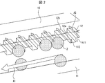
- FIG. 2 is a schematic diagram showing a structure in the vicinity of the side channel 12 of the channel device 1 according to an embodiment of the present invention.
- a liquid flow A ⁇ b> 1 in the main flow path 11 and a liquid flow A ⁇ b> 2 in the side flow path 12 are generated.
- the direction of arrows A1 and A2 represents the direction in which the liquid flows.
- the fine particles 2 that have moved on the flow A1 approach the vicinity of the side flow path 12 (the first connecting portion 12a)
- the movement direction changes to the side flow path 12 on the flow A2.
- the height h 12 of the side flow path 12 in the first connection part 12a is smaller than the particle diameter of the fine particles 2 to be concentrated.
- the fine particles 2 having a particle diameter larger than the height h 12 of the side flow path 12 cannot pass through the first connection portion 12 a and cannot enter the side flow path 12. Therefore, the fine particles 2 stop moving (captured) at the first connecting portion 12a.
- the fine particles 2 can be concentrated in the chamber 15 provided at the end of the main flow path 11.
- FIG. 2 illustrates a case where the height of the side channel 12 is smaller than the particle size of the fine particles 2, but the width of the side channel 12 is smaller than the particle size of the fine particles 2 as described above. Also good. In addition, when the height of the side channel 12 is smaller than the particle size of the fine particles 2, the side channel 12 can be processed more easily than when the width of the side channel 12 is smaller than the particle size of the fine particles 2. There is.
- the main channel 11 has such a size that the fine particles 2 can flow.
- the height h 12 of the side channels 12 of the first connecting portion 12a is lower than the height h 11 of the main flow path 11 in the first connecting portion 12a. That is, a step is provided between the main channel 11 and the side channel 12.
- the length, width, height, and number of the side flow paths 12 can be appropriately set according to the amount of liquid flowing through the flow path device 1, the number of fine particles contained in the liquid, and the like.
- the length of the side channel represents the length along the direction in which the liquid flowing through the side channel flows. It is preferable that the width and height of the side flow path 12 are narrow so that the fine particles to be captured do not aggregate. For example, it is preferable that one fine particle is captured in one side channel 12. Also, in general, the shorter the length of the side channel 12 and the greater the number, the shorter the time required for discharging the liquid, which is preferable.
- the length of the side channel 12 may be 1 to 100 ⁇ m or 1 to 50 ⁇ m.
- the width and / or height of the side channel 12 may be 0.05 to 10 ⁇ m, 0.05 to 5 ⁇ m, 0.05 to 0.5 ⁇ m, 0.05 It may be up to 0.15 ⁇ m.
- the number of the side flow paths 12 may be one or a plurality, for example, 1 to 1000, 100 to 800, 300 to 700. Also good.
- the structure in which the width or height of the side flow path 12 is smaller than the particle diameter of the fine particles 2 is sufficient if it is satisfied in the first connection portion 12a. That is, the width or height of the side flow path 12 in a portion other than the first connection portion 12 a may be equal to or larger than the particle diameter of the fine particles 2.
- a plurality of side flow paths 12 having different heights may be installed in the flow path device 1. According to such a configuration, fine particles having different particle diameters can be captured by one flow path device. Moreover, you may connect the several flow path device 1 from which the height of the side flow path 12 differs. According to such a configuration, fine particles having different particle diameters can be separated and concentrated in each flow channel device 1 from the same liquid sample (for example, red blood cells, white blood cells, and platelets are separated and concentrated from the blood). can do).
- the fine particles flowing through the main flow channel 11 as a design that allows some of the fine particles to pass through the side flow channel 12, the fine particles may be separated according to the particle size.
- fine particles that cannot pass through the side channel 12 remain in the main channel 11, whereas particles that can pass through the side channel 12 flow out of the main channel 11. In this way, only fine particles that cannot pass through the side channel 12 can be separated and concentrated.
- the particles that can pass through the side channel 12 collect the liquid flowing out from the side channel 12, and again use the channel device 1 (the one in which at least one of the width and height of the first connecting portion 12a is changed). It can be recovered and concentrated.
- the flow channel device 1 may have a configuration in which one row of a plurality of side flow channels 12 is provided on the side surface of the main flow channel 11 or a configuration in which two or more rows are provided.
- FIG. 1 illustrates a configuration in which two rows including a plurality of side flow paths 12 are provided.
- the surface of the side channel 12 (the surface in contact with the liquid) is preferably hydrophilic.
- the liquid discharge path 13 may be connected to the side of the side flow path 12 opposite to the connection section (first connection section 12a) with the main flow path 11.
- the connection part between the side flow path 12 and the liquid discharge path 13 is referred to as a second connection part 12b.
- the liquid discharge path 13 is a flow path for discharging the liquid that flows from the main flow path 11 to the side flow path 12.
- the shape of the liquid discharge path is not particularly limited.
- the liquid discharge path 13 only needs to fulfill the function of discharging the liquid that has flowed from the main flow path 11 into the side flow path 12, and thus may not be formed as a flow path but may be a liquid reservoir. Further, in order to enhance the function of discharging the liquid from the main flow path 11, a tube or the like for discharging the liquid may be connected from the liquid discharge path 13 to the outside of the range shown in FIG.
- the length, width, and height of the liquid discharge path 13 can be set as appropriate according to the amount of liquid flowing through the flow path device 1.
- the length of the liquid discharge path represents the length along the direction in which the liquid flowing through the liquid discharge path flows.
- the length of the liquid discharge path 13 may be 1 to 20 mm
- the width may be 50 to 200 ⁇ m
- the height may be 10 to 200 ⁇ m.
- the liquid discharge path 13 has a width and a height at which liquid can be discharged by pressure, and preferably has a width greater than the width of the side flow path 12 and a height greater than the height of the side flow path 12.
- fine particles particles having a size that can pass through the side flow path 12
- the height of the liquid discharge path 13 and the height of the side flow path 12 are intended to be the height of the second connection portion 12b.
- a configuration in which a plurality of side flow paths 12 are connected to one liquid discharge path 13 may be employed.
- a configuration in which a plurality of side flow paths 12 are connected to one liquid discharge path 13 may be employed.
- two or more sets of such configurations may be provided in the flow channel device 1.
- the surface of the liquid discharge channel 13 (the surface in contact with the liquid) is preferably hydrophilic.
- a chamber 15 for concentrating fine particles is provided at one end of the main flow path 11.
- the chamber 15 is provided at the end of the main channel 11 opposite to the side where the liquid is introduced (liquid introducing portion 14). That is, the chamber 15 is provided downstream of the flow of the main flow path 11.
- the chamber 15 is a portion into which fine particles to be concentrated are sent.
- the volume of the chamber 15 can be appropriately set according to the particle size and / or number of the captured fine particles.
- the fine particles 2 released from the first connection portion 12a reach the chamber 15 through the main flow path 11. As described above, the excess liquid is discharged to the side flow path 12, so that the concentration of the fine particles is increased in the chamber 15 as compared with the time of introduction.
- the surface of the chamber 15 (surface in contact with the liquid) is preferably hydrophilic.
- Liquid stop part The main flow path 11 and the chamber 15 are preferably connected via a liquid stopper.
- the liquid stopper is a part having a function of temporarily preventing the liquid from flowing between the main flow path 11 and the chamber 15. By providing the liquid stopper, the liquid can be prevented from flowing into the chamber 15 while the liquid is discharged and the fine particles are captured.
- the liquid stopper is the water-repellent channel 16. Since the surface of the water repellent flow path 16 is water repellent, when the liquid introduced into the main flow path 11 is an aqueous dispersion, the water repellent flow path 16 cannot normally be overcome. It is preferable that the water repellent flow channel 16 has a water repellent surface (surface in contact with the liquid) and a flow channel design that allows the liquid to get over when a pressure difference is generated.
- the surface of the water repellent channel 16 may be formed with, for example, a silicon carbide (SiC X ) film, may have a functional group such as a methyl group, or may be formed with a fluorine compound. Good (for example, introducing a trifluoromethyl group on the surface).
- the hydrophilic channel can be used as a liquid stopper.
- the surfaces of the main flow path 11, the side flow path 12, the liquid discharge path 13, and the chamber 15 are nonpolarity. It is preferable to make the surface in contact with the dispersion liquid hydrophobic. In order to make these surfaces hydrophobic, for example, a silicon carbide (SiC X ) film is formed, a functional group such as a methyl group is introduced, or a surface is formed with a fluorine compound (for example, a trivalent surface is formed on the surface). A fluoromethyl group is introduced).
- the liquid stopper is a mechanism for temporarily closing the main flow path 11.
- An example of such a mechanism is a diaphragm type microvalve driven by air pressure.
- a liquid pressure difference is generated so that the liquid introduction side (liquid introduction part 14 side) in the main flow path 11 becomes high pressure, or the main flow path 11 11 may be released.
- the flow channel device 1 may have a configuration in which a pressure difference between the liquids is generated in the main flow channel 11 so that the liquid introduction side becomes a high pressure (that is, a configuration in which a positive pressure is generated).
- a fluid pressure control device may be connected to the side of the main channel 11 where the liquid is introduced (liquid introduction unit 14).
- the following advantages are obtained by generating a pressure difference of the liquid so that the liquid introduction side becomes a high pressure. That is, in a state where the liquid is discharged to the side flow path 12 and the fine particles are captured by the first connection portion 12a, the captured fine particles 2 are released by flowing an additional liquid by applying a positive pressure. And can be moved to the chamber 15. Further, by applying a positive pressure, the fine particles 2 can be fed into the chamber 15 over the liquid stopper (water repellent flow path 16 or the like).
- the flow channel device 1 may have a configuration that causes a pressure difference of the liquid between the first connection portion 12a and the second connection portion 12b of the side flow channel 12.
- a configuration may be, for example, a configuration that causes a liquid pressure difference between the main channel 11 and the side channel 12.
- a configuration in which a fluid pressure control device is connected to the main flow path 11, the side flow path 12 and / or the liquid discharge path 13 can be given.
- the following advantages are produced.
- the fluid pressure at the first connection portion 12a is higher than the fluid pressure at the second connection portion 12b (when the first connection portion 12a side is positive or the second connection portion 12b side is negative pressure)
- the flow rate of the liquid flowing through the side flow path 12 toward the liquid discharge path 13 increases, and the time required to discharge the liquid can be shortened.
- the fluid pressure in the first connection portion 12a is lower than the fluid pressure in the second connection portion 12b, the liquid flows backward from the liquid discharge passage 13 to the side passage 12, so that the first connection portion 12a The trapped fine particles can be released into the main flow path 11.
- various sensors may be connected to the flow channel device 1.
- the sensor can be connected to the chamber 15 or the like.
- the concentration target may be a liquid containing fine particles, and the particle size, concentration and type of fine particles, the type of dispersion medium, and the like are not particularly limited.
- a liquid containing the fine particles is also referred to as a dispersion.
- the particle diameter of the fine particles is a value determined by a known method for calculating the particle diameter such as a major axis diameter, a minor axis diameter, a constant direction diameter, an equivalent diameter, an effective diameter, and the like. You can choose.
- the particle diameter of the fine particles may be 100 ⁇ m or less.
- the concentration of the fine particles can be measured by a measuring method such as an electrical detection band method.
- the concentration of the fine particles may be, for example, 10 10 particles / mL or less.
- the fine particles may be inorganic fine particles or organic fine particles.
- the dispersion medium may be water or an organic dispersion medium. From the viewpoint of easy handling, the dispersion medium is preferably water.
- the liquid containing fine particles may be derived from a living body such as blood, saliva, runny nose or urine.
- a living body such as blood, saliva, runny nose or urine.
- red blood cells, white blood cells, platelets, pollen, bacteria, viruses, and other cells can be regarded as fine particles.
- the fine particle concentration method includes an introduction step of introducing a liquid containing fine particles into the main flow path, and discharging the liquid to a side flow path connected to a side surface of the main flow path.
- the fine particle concentration method may be performed using the flow channel device according to the embodiment of the present invention described above.
- the above-mentioned fine particle concentration method can concentrate a very small amount of fine particles contained in a liquid to a high concentration. Therefore, for example, when a virus is selected as the microparticle, the virus contained in the sample collected from the subject can be concentrated. For this reason, the detection of the said virus can be made easy and it is useful also for the early diagnosis of an infectious disease.
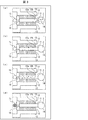
- FIG. 3 is a schematic diagram showing an outline of a fine particle concentration method according to an embodiment of the present invention.
- the fine particle concentration method includes an introducing step of introducing a liquid containing fine particles into the main channel.
- the liquid containing the fine particles 2 is introduced into the liquid introduction unit 14.
- the fine particles 2 flow through the main channel 11 together with the liquid.
- the fine particle concentration method includes a capturing step of discharging the liquid to a side flow channel connected to a side surface of the main flow channel and capturing the fine particles at a connection portion between the side flow channel and the main flow channel.
- the fine particles 2 riding on the flow from which the liquid is discharged toward the side flow path 12 are captured at the first connecting portion 12a as shown in FIG. This is because the particle diameter of the fine particles 2 is larger than at least one of the height and the width of the side flow path 12 in the first connection portion 12a.
- the pressure in the first connection portion 12a is higher than the pressure in the second connection portion 12b, the flow rate of the liquid flowing through the side flow path 12 toward the liquid discharge path 13 increases, and the liquid is discharged. The time required can be reduced. In the capturing step, it is preferable that all the liquid is discharged to the side channel 12.
- the fine particle concentration method includes a release step of releasing the captured fine particles into the main channel.
- the fine particles 2 captured by the first connecting portion 12a are discharged toward the main channel 11.
- Examples of the method for releasing the fine particles 2 include the following: (1) Pressure that is applied to the side flow path 12 to promote the discharge of the liquid and at which the first connection portion 12a side has a high pressure (2) Apply pressure to the side flow path 12 so that the fluid pressure at the first connection portion 12a is lower than the fluid pressure at the second connection portion 12b; (3) the main flow path 11 And distribute additional liquid.
- the fine particle concentration method includes a concentration step of concentrating the discharged fine particles in a chamber provided at one end of the main flow path.
- the concentration step as shown in FIG. 3 (d), the fine particles 2 that have been discharged to the main flow path 11 are added to a small amount of liquid (for example, liquid that has flowed back from the side flow path 12 or added to the main flow path 11.
- the liquid is moved to the chamber 15.
- the fine particles 2 that have moved to the chamber 15 are in a concentrated state.
- “concentrating fine particles” is intended to increase the number of fine particles contained in the liquid per unit volume as compared with the time of introducing the liquid.
- the liquid containing fine particles can be concentrated usually 100 times or more, preferably 500 times or more, more preferably 1000 times or more.
- a liquid stopper water repellent flow path 16 or the like
- a liquid pressure difference is generated so that the liquid introduction side in the main flow path 11 has a high pressure.
- the concentration step can be performed at an arbitrary timing.
- the flow channel device may be a member having a micro flow channel according to a conventional method, and optionally connected to a fluid pressure control device, various sensors, or the like.
- the manufacturing method of the flow channel device can be appropriately selected according to the material of the flow channel device.
- the material of the flow path device may be a silicone resin such as polydimethylsiloxane, an olefin resin such as a polymethyl methacrylate resin, or a cyclic olefin copolymer, or glass.
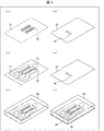
- the manufacturing method of the flow channel device may be based on soft lithography, nanoimprint, or thin film lamination, and is not particularly limited. Below, the manufacturing method by the soft lithography which used the silicone resin as an example is demonstrated based on FIG.
- a flow path template is prepared as follows.
- a photoresist is applied on a substrate 21 made of an appropriate material (silicon or the like) to form a resist film.
- a flow path pattern is formed by exposure.
- the pattern 23 corresponding to the main flow path may be formed as shown in FIG. 4B.
- the step existing in the first connection portion can be produced by changing the thickness of the resist film.
- a silicone resin is poured into the mold prepared in the above-described process. After the silicone resin is cured by thermosetting, as shown in FIG. 4C, a member 24 to which the flow path pattern is transferred is obtained.
- the surface of the member 24 that comes into contact with the liquid may optionally be subjected to a hydrophilic treatment.
- the hydrophilization treatment can be performed by forming a hydrophilic film by a pulse plasma CVD method, a surface treatment by an oxygen plasma method, a surface modification by vacuum ultraviolet light, or the like.
- a substrate 25 corresponding to the bottom surface of the flow path is prepared.
- the surface of the substrate 25 may be subjected to a hydrophilic treatment and / or a water repellent treatment.
- a region other than the water-repellent region 26 may be subjected to a hydrophilic treatment as shown in FIG. .
- the hydrophilization treatment can be performed by forming a hydrophilic film by a pulse plasma CVD method, a surface treatment by an oxygen plasma method, a surface modification by vacuum ultraviolet light, or the like.
- the water repellent treatment can be performed by forming a water repellent film by a pulse plasma CVD method, a fluorine gas surface treatment method, or the like.
- a negative photosensitive resist (SU-8 2000.5, manufactured by MicroChem) is applied onto a 100 mm diameter silicon substrate (4 inch silicon wafer, manufactured by Electronics End Materials Corporation), and a 0.5 ⁇ m thick resist is applied. A film was formed. Subsequently, the pattern of the side flow path was formed by LED drawing using a maskless exposure apparatus (high-intensity LED drawing apparatus, manufactured by PMT Corporation). The width of the side channel was 5 ⁇ m, the height was 0.5 ⁇ m, the length was 50 ⁇ m, and the number was 660. The interval between the side channels was 15 ⁇ m.
- the size of the opening of the side channel in the first connection portion is 5 ⁇ m ⁇ 0.5 ⁇ m, fine particles larger than this cannot pass through the side channel. That is, fine particles having a particle size equal to or greater than the height of the side channel (0.5 ⁇ m) cannot pass through the side channel.
- a negative photosensitive resist (SU-8-3050, manufactured by MicroChem) was applied on the silicon substrate to form a resist film having a thickness of 30 ⁇ m.
- the pattern of the main flow path, the liquid discharge path, the liquid introduction part, and the chamber was formed using the exposure apparatus (mask aligner) (PEM-800, manufactured by Union Optical Co., Ltd.).
- the main channel had a width of 200 ⁇ m, a height of 30 ⁇ m, and a length of 6 mm.
- the liquid discharge channel had a width of 100 ⁇ m and a channel height of 30 ⁇ m.
- Polydimethylsiloxane (Sylgard 184 (registered trademark) Silicone Elastomer, manufactured by Toray Dow Corning Co., Ltd.) was poured into a mold having a flow path pattern produced by the above-described process, and was thermally cured. Thereafter, the polydimethylsiloxane channel structure to which the channel pattern was transferred was cut out from the mold.
- Oxygen plasma surface treatment was performed on the surface of the above-described flow channel structure that mates with a glass substrate described later using a plasma cleaner apparatus (FEMTO-CUTE-MP, manufactured by Femto Science). Thereby, the surface of the above-mentioned channel structure was hydrophilized.
- a SiC X water-repellent film is formed on the surface of a quartz glass substrate (4-inch synthetic quartz glass wafer, manufactured by Daiko Seisakusho Co., Ltd.) using a pulse plasma CVD method on the region corresponding to the water-repellent flow path. Formed.
- a pulse plasma CVD apparatus experimental, manufactured by Shinko Seiki Co., Ltd.
- a hydrophilic film of SiO X was formed on the surface of the quartz glass substrate other than the water-repellent film using a pulse plasma CVD method.
- a pulse plasma CVD apparatus for experiment, manufactured by Shinko Seiki Co., Ltd. was used.
- the obtained hydrophilized flow channel structure was bonded to a quartz glass substrate.
- a hole with a diameter of 4 mm was made in the liquid introduction part and connected to a fluid pressure control device (ELVEFLOW OB1, manufactured by Elvesys) during the concentration process.
- a hole with a diameter of 2 mm was formed in a part of the liquid discharge path and connected to a fluid pressure control device (ELVEFLOW OB1, manufactured by Elvesys).
- Example 1 Concentration of carboxy group-modified polystyrene fine particles
- a dispersion Polybead (registered trademark) Carboxylate Microspheres 6.00 ⁇ m, manufactured by Polysciences) containing carboxy group-modified polystyrene fine particles having a particle size of 6 ⁇ m was used.
- a phosphate buffer By diluting the dispersion with a phosphate buffer to prepare a dispersion having a fine particle concentration of 10 4 cells / mL (liquid volume 30 [mu] L).
- the dispersion was poured into the flow channel device produced in the above production example to concentrate the fine particles.
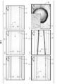
- FIG. 5 is a diagram showing a result of observing a state in which fine particles are concentrated with a digital microscope (KH-8700, manufactured by Hilox Co., Ltd.).
- FIG. 5A shows a flow channel device before introducing the dispersion. The dispersion prepared as described above was dropped into the liquid introduction part and circulated in the flow path.
- FIGS. 5B to 5E the liquid flows into the side channel 12, so that each side channel is difficult to see due to the influence of the refractive index.
- FIG. 5B shows a state in which the fine particles 2 are flowing through the main flow path 11.
- FIG. 5C shows a state in which the fine particles 2 are captured by the side flow path 12. As a result, the liquid discharge was completed in about 10 minutes. Further, as shown in FIG. 5D, the fine particles 2 were captured in the opening of the side channel 12.
- the concentration of the carboxy group-modified polystyrene fine particles transferred to the chamber was about 10 7 particles / mL, and was concentrated about 800 times.
- Example 1-2 A flow channel device was fabricated in the same manner as in the above production example except that the length of the side flow channel was 100 ⁇ m. An experiment similar to Example 1-1 was performed using carboxy group-modified polystyrene fine particles having a particle diameter of 1 ⁇ m.
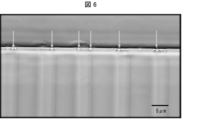
- FIG. 6 is a diagram showing a result of observing captured fine particles with a digital microscope (KH-8700, manufactured by Hilox Co., Ltd.). The arrows in FIG. 6 indicate the captured carboxy group-modified polystyrene fine particles.
- concentration of the carboxyl group modification polystyrene fine particle which moved to the chamber was about 10 ⁇ 7 > piece / mL, and was concentrated about 800 times.
- Example 2 Isolation of E. coli
- a phosphate buffer containing Escherichia coli Escherichia coli, 1 ⁇ m ⁇ 5 ⁇ m cylindrical shape
- a flow channel device prepared in the same manner as in the above production example except that the length of the side flow channel is 100 ⁇ m. From which E. coli was captured.
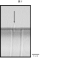
- FIG. 7 is a diagram showing a result of observing captured E. coli with a digital microscope (KH-8700, manufactured by Hilox Co., Ltd.). The arrows in FIG. 7 indicate captured E. coli.
- a digital microscope KH-8700, manufactured by Hilox Co., Ltd.
- the arrows in FIG. 7 indicate captured E. coli.
- the present invention can be used, for example, in a technical field (such as early diagnosis of infectious diseases) in which detection of a minute amount of fine particles is useful.
Landscapes
- Chemical & Material Sciences (AREA)
- Health & Medical Sciences (AREA)
- Life Sciences & Earth Sciences (AREA)
- Engineering & Computer Science (AREA)
- General Health & Medical Sciences (AREA)
- Biochemistry (AREA)
- Analytical Chemistry (AREA)
- Organic Chemistry (AREA)
- Chemical Kinetics & Catalysis (AREA)
- Physics & Mathematics (AREA)
- Genetics & Genomics (AREA)
- Biotechnology (AREA)
- Wood Science & Technology (AREA)
- Zoology (AREA)
- Bioinformatics & Cheminformatics (AREA)
- Immunology (AREA)
- General Physics & Mathematics (AREA)
- Pathology (AREA)
- Clinical Laboratory Science (AREA)
- Microbiology (AREA)
- General Engineering & Computer Science (AREA)
- Biomedical Technology (AREA)
- Tropical Medicine & Parasitology (AREA)
- Medicinal Chemistry (AREA)
- Dispersion Chemistry (AREA)
- Hematology (AREA)
- Virology (AREA)
- Fluid Mechanics (AREA)
- Computer Hardware Design (AREA)
- Microelectronics & Electronic Packaging (AREA)
- Molecular Biology (AREA)
- Apparatus Associated With Microorganisms And Enzymes (AREA)
- Separation Of Solids By Using Liquids Or Pneumatic Power (AREA)
- Filtration Of Liquid (AREA)
- Physical Or Chemical Processes And Apparatus (AREA)
- Micromachines (AREA)
Abstract
静電相互作用によらずに流体力学的流動のみで液体中の微粒子を濃縮できる流路デバイスを提供する。本発明の一態様に係る流路デバイス(1)は、微粒子を含む液体を流動させるための主流路(11)と、上記主流路(11)の一端に設けられた、微粒子を濃縮するためのチャンバー(15)と、上記主流路(11)の側面に接続されており、余分な液体を排出するための側流路(12)と、を備え、上記側流路(12)の高さおよび幅の少なくともいずれか一方は上記微粒子の粒径に比べて小さい。
Description
本発明は、流路デバイスおよび微粒子濃縮方法に関する。
液体中に低濃度で含まれる微粒子を高感度で検出するための前処理として、微小流路を基本構造とする流路デバイスを用いた、微粒子濃縮方法が注目を集めている。とりわけ、微小流路と微小電極とを組み合わせた誘電泳動法は、液体中における代表的な微粒子操作技術である。
例えば、非特許文献1は、誘電泳動法により、全血から細菌を分離したことを報告している。同様に、非特許文献2は、誘電泳動法により、生きている細菌と死んでいる細菌とを分離したことを報告している。これらの誘電泳動法は、電界強度が極大となる微小電極外縁部への微粒子の捕捉および脱離を基本原理としている。
また、流路デバイスにおいて、流路を流れる微粒子の大きさに応じて、当該微粒子を異なる流路に分配する技術が知られている。このような技術は、例えば、特許文献1~3に開示されている。
L. D'Amico et al. (2017) Lab on a Chip, Vol.17 (Issue 7), pp.1340-1348
Blanca H. Lapizco-Encinas et al. (2004) Anal. Chem., Vol.76 (Issue 6), pp.1571-1579
しかしながら、誘電泳動法のように静電相互作用を用いた微粒子濃縮方法では、電極表面に微粒子が吸着してしまう可能性がある。また、上記濃縮方法では、空間的な有効電場範囲が限定される。さらに、上記濃縮方法では、微粒子の性質および/または微粒子と液体との誘電比率の差に応じて泳動パラメータを設定しなければならない。
本発明の一態様は、上記従来の問題点に鑑みてなされたものであって、静電相互作用によらずに液体中の微粒子を濃縮する流路デバイスおよび微粒子濃縮方法を実現することを目的とする。
本発明者らは、上記目的を達成するために鋭意検討を重ねた結果、特定の流路構造を有する流路デバイスによって、静電相互作用を用いずに流体力学的流動のみで微粒子を捕捉および濃縮できることを見出し、本発明を完成するに至った。すなわち、本発明は以下の構成を包含している。
<1>微粒子を含む液体を流動させるための主流路と、上記主流路の一端に設けられた、微粒子を濃縮するためのチャンバーと、上記主流路の側面に接続されており、余分な液体を排出するための側流路と、を備え、上記側流路の高さおよび幅の少なくともいずれか一方は上記微粒子の粒径に比べて小さいことを特徴とする流路デバイス。
<2>上記側流路における上記主流路との接続部との反対側には、該側流路の幅以上の幅および該側流路の高さ以上の高さを有する液体排出路が接続されていることを特徴とする<1>に記載の流路デバイス。
<3>上記主流路と上記チャンバーとの間に、液止め部が設けられていることを特徴とする<1>または<2>に記載の流路デバイス。
<4>上記側流路が複数設けられていることを特徴とする<1>~<3>のいずれか1つに記載の流路デバイス。
<5>微粒子を含む液体を、主流路に導入する導入工程と、上記主流路の側面に接続された側流路へ上記液体を排出するとともに、上記側流路と上記主流路との接続部において上記微粒子を捕捉する捕捉工程と、上記捕捉された微粒子を上記主流路へと放出する放出工程と、上記放出された微粒子を上記主流路の一端に設けられたチャンバーにて濃縮する濃縮工程と、を含み、上記側流路の高さおよび幅の少なくともいずれか一方は上記微粒子の粒径に比べて小さいことを特徴とする微粒子濃縮方法。
<6>上記側流路における上記主流路との接続部との反対側には、該側流路の幅以上の幅および該側流路の高さ以上の高さを有する液体排出路が接続されていることを特徴とする<5>に記載の微粒子濃縮方法。
<7>上記主流路と上記チャンバーとの間に、液止め部が設けられていることを特徴とする<5>または<6>に記載の微粒子濃縮方法。
<8>上記側流路が複数設けられていることを特徴とする<5>~<7>のいずれか1つに記載の微粒子濃縮方法。
本発明の一態様によれば、静電相互作用によらずに液体中の微粒子を濃縮する流路デバイスおよび微粒子濃縮方法を提供することができるという効果を奏する。
以下、本発明の実施の形態の一例について詳細に説明するが、本発明は、これらに限定されない。なお、本明細書において特記しない限り、数値範囲を表す「A~B」は、「A以上、B以下」を意味する。また、説明の便宜上、同じ機能を有する部材については、同じ符号を付記し、その説明を省略する。
〔1.流路デバイス〕
本発明の一実施形態に係る流路デバイスは、微粒子を含む液体を流動させるための主流路と、上記主流路の一端に設けられた、微粒子を濃縮するためのチャンバーと、上記主流路の側面に接続されており、余分な液体を排出するための側流路と、を備え、上記側流路の高さおよび幅の少なくともいずれか一方は上記微粒子の粒径に比べて小さいことを特徴としている。
本発明の一実施形態に係る流路デバイスは、微粒子を含む液体を流動させるための主流路と、上記主流路の一端に設けられた、微粒子を濃縮するためのチャンバーと、上記主流路の側面に接続されており、余分な液体を排出するための側流路と、を備え、上記側流路の高さおよび幅の少なくともいずれか一方は上記微粒子の粒径に比べて小さいことを特徴としている。
上記流路デバイスにより、側流路へ向かう流れに乗った微粒子を、側流路の入り口にて捕捉することができる。また、余分な液体を側流路へ排出することができるため、主流路に接続されたチャンバー内にて微粒子を濃縮することができる。従って、上記流路デバイスにより、静電相互作用によらずに液体中の微粒子を濃縮することができる。
側流路から余分な液体を排出し、微粒子を濃縮することができる点において、本発明の一実施形態に係る流路デバイスは、特許文献1~3に記載の技術とは異なっている。以下、簡潔に説明する。
特許文献1に開示されているがん細胞自動分離装置は、がん細胞の代表径よりも流路高さが低い部分を設けることによって、がん細胞とがん細胞以外の細胞とを、互いに異なる流路に導入するものである。特許文献2に開示されている微粒子操作ユニットは、一定の大きさ以上の微粒子に対する透過制限領域などを備えることによって、流路内を流動する微粒子の流動方向を操作するものである。特許文献3に開示されている微粒子分離装置は、フィルタ部を通過できる微粒子と、通過できない微粒子とを、異なる排出口へと導入するものである。
しかし、以上の文献に記載されている装置は、大きさによって分離した微粒子を、異なる流路に導入するものの、微粒子を含む液体から余分な液体を分離して排出する(すなわち、微粒子を濃縮する)という機能は有していない。一方、本発明の一実施形態に係る流路デバイスは、側流路を備えているので、微粒子を大きさによって分離することができる上に、余分な液体を排出して微粒子を濃縮することができる。
ここで、「余分な液体」とは、例えば、微粒子を分散させている分散媒である。一「余分な液体」には、濃縮の対象でない微粒子(濃縮の対象となる微粒子よりも粒径の小さい微粒子)が含まれていてもよい。本発明の一実施形態に係る流路デバイスは、余分な液体を側流路を通じて排出し、濃縮した微粒子をチャンバーに溜めることができる。
本明細書において、流路デバイスとは、液体を流動させる流路構造を備えたデバイスを意図している。この液体の流動は毛細管流動によるものであることが好ましい。
本発明の一実施形態に係る流路デバイスの構造について、図1に基づいて説明する。図1は、本発明の一実施形態に係る流路デバイス1の構造を表す模式図である。流路デバイス1は、主流路11、側流路12、液体排出路13、液体導入部14、チャンバー15および液止め部(撥水性流路16)を備えている。
なお、本明細書において、流路等が「接続されている」とは、液体が流通可能なように連通していることを意図している。
<1-1.主流路>
主流路11は、微粒子を含む液体が流れる流路である。主流路11の長さ、幅および高さは、流路デバイス1に流通させる微粒子の粒径および液体の量、主流路11と接続している側流路12の本数などに応じて適宜設定されうる。一例を挙げると、主流路11の長さは1~20mm、幅は100~500μm、高さは10~200μmとすることができる。なお、本明細書において、主流路の長さとは、主流路を流通する液体が流れる方向に沿った長さを表す。
主流路11は、微粒子を含む液体が流れる流路である。主流路11の長さ、幅および高さは、流路デバイス1に流通させる微粒子の粒径および液体の量、主流路11と接続している側流路12の本数などに応じて適宜設定されうる。一例を挙げると、主流路11の長さは1~20mm、幅は100~500μm、高さは10~200μmとすることができる。なお、本明細書において、主流路の長さとは、主流路を流通する液体が流れる方向に沿った長さを表す。
主流路11の形状は、図1に示されているような直線状に限定されない。例えば、主流路11は、蛇行した流路であってもよい。液体に含まれる微粒子が側流路に接触する機会が増加するという観点からは、主流路11の形状は、蛇行していることが好ましい。一方、流路設計が容易であるという観点からは、主流路11の形状は、直線状であることが好ましい。また、主流路11の、液体の流れる方向に垂直な断面の形状も特に限定されず、矩形であってもよく、円形であってもよい。
また、主流路11の一端には液体導入部14が設けられていてもよい。液体導入部14は、主流路11に微粒子を含む液体を流通させるために、上記微粒子を含む液体を導入する部分である。液体導入部14は、主流路11の一端に単に孔が形成された構成であってもよく、図1に示す液溜め(リザーバー)のような構成であってもよい。液体導入部14の容量は、導入する微粒子を含む液体の量などに応じて、適宜設定されうる。
流路デバイス1において、主流路11の表面(液体と接する面)は、親水性であることが好ましい。例えば、主流路11の表面は、酸化ケイ素(SiOX)膜が形成されていてもよく、ヒドロキシル基、カルボニル基、アルデヒド基またはカルボキシル基などの官能基を有していてもよい。また、主流路11の表面は、酸素プラズマ法、真空紫外光処理法、フッ素ガス処理法によって表面処理を施されていてもよい。
主流路11の表面が親水性を示すことにより、導入された液体が水性分散液である場合に、毛細管流動の効果によって上記水性分散液が主流路11を流れやすくなる。このため、微粒子の濃縮に要する時間が短縮される。
<1-2.側流路>
主流路11の側面には、側流路12が接続されている。以下、主流路11と側流路12の接続部を、第1の接続部12aと呼ぶ。すなわち、第1の接続部12aは、主流路11から側流路12へ向かう流れの入り口とも言える。側流路12は、主流路11を流れる液体を主流路11外へと導く流路である。側流路12によって、余分な液体を排出することができる。また、側流路12の高さおよび幅の少なくともいずれか一方は微粒子2の粒径に比べて小さい。それゆえ、側流路12へ向かう流れに乗った微粒子2を、第1の接続部12aにて捕捉することができる。
主流路11の側面には、側流路12が接続されている。以下、主流路11と側流路12の接続部を、第1の接続部12aと呼ぶ。すなわち、第1の接続部12aは、主流路11から側流路12へ向かう流れの入り口とも言える。側流路12は、主流路11を流れる液体を主流路11外へと導く流路である。側流路12によって、余分な液体を排出することができる。また、側流路12の高さおよび幅の少なくともいずれか一方は微粒子2の粒径に比べて小さい。それゆえ、側流路12へ向かう流れに乗った微粒子2を、第1の接続部12aにて捕捉することができる。
図2は、本発明の一実施形態に係る流路デバイス1の側流路12近傍の構造を表す模式図である。ここで、流路デバイス1内を液体が流通する際には、主流路11における液体の流れA1と、側流路12における液体の流れA2が生じる。A1およびA2の矢印の方向は液体が流れる方向を表している。流れA1に乗って移動していた微粒子2が、側流路12の近傍(第1の接続部12a)に近づくと、流れA2に乗って側流路12へと移動方向を変える。しかし、第1の接続部12aにおける側流路12の高さh12は、濃縮対象の微粒子2の粒径に比べて小さい。このような構造を取る結果、側流路12の高さh12よりも粒径の大きい微粒子2は、第1の接続部12aを通過できず、側流路12へ入ることができない。そのため、微粒子2は、第1の接続部12aで移動を停止する(捕捉される)。
その後、再度、微粒子2を流れA1に乗るように放出すれば、主流路11の末端に設けられたチャンバー15において微粒子2を濃縮することができる。
図2では、側流路12の高さが微粒子2の粒径に比べて小さい場合を例示しているが、上述のように側流路12の幅が微粒子2の粒径に比べて小さくてもよい。なお、側流路12の高さが微粒子2の粒径より小さい場合は、側流路12の幅が微粒子2の粒径より小さい場合に比べて側流路12の加工が容易であるという利点がある。
なお、主流路11は、微粒子2が流動できる大きさを有している。従って、図2において、第1の接続部12aにおける側流路12の高さh12は、第1の接続部12aにおける主流路11の高さh11よりも低い。すなわち、主流路11と側流路12の間に段差が設けられている。
側流路12の長さ、幅、高さおよび本数は、流路デバイス1に流通させる液体の量、上記液体に含まれる微粒子の数などに応じて、適宜設定されうる。なお、本明細書において、側流路の長さとは、側流路を流通する液体が流れる方向に沿った長さを表す。側流路12の幅および高さは、捕捉したい微粒子が凝集しない程度に狭いことが好ましい。例えば、1本の側流路12において1個の微粒子が捕捉されることが好ましい。また、一般的に、側流路12の長さが短く、本数が多いほど、液体の排出に要する時間が短くなり、好ましい。
一例を挙げると、側流路12の長さは1~100μmであってもよく、1~50μmであってもよい。側流路12の幅および/または高さは0.05~10μmであってもよく、0.05~5μmであってもよく、0.05~0.5μmであってもよく、0.05~0.15μmであってもよい。側流路12の本数は1本であっても、複数であってもよく、例えば、1~1000本であってもよく、100~800本であってもよく、300~700本であってもよい。
なお、側流路12の幅または高さが微粒子2の粒径よりも小さい構造は、第1の接続部12aにおいて満たされていれば充分である。すなわち、第1の接続部12a以外の部分における、側流路12の幅または高さは、微粒子2の粒径以上であってもよい。
ここで、流路デバイス1中に、異なる高さを有する複数の側流路12を設置してもよい。このような構成によれば、異なる粒径の微粒子を、1つの流路デバイスで捕捉することができる。また、側流路12の高さが異なる複数の流路デバイス1を連結してもよい。このような構成によれば、同じ液体サンプルから、異なる粒径の微粒子を、それぞれの流路デバイス1において分離および濃縮することができる(例えば、血液中から、赤血球、白血球および血小板を分離および濃縮することができる)。
また、主流路11を流れる微粒子のうち、一部の微粒子が側流路12を通過できる設計として、微粒子を粒径に応じて分離させてもよい。このような構成とすれば、側流路12を通過できない微粒子が主流路11に留まるのに対し、側流路12を通過できる粒子は主流路11から流出する。このようにして、側流路12を通過できない微粒子のみを分離し、濃縮することができる。そして、側流路12を通過できる粒子は、側流路12から流出する液体を回収し、再度流路デバイス1(第1の接続部12aの幅および高さの少なくとも一方を変更したもの)を利用して、回収・濃縮することができる。
また、流路デバイス1は、複数の側流路12からなる列を、主流路11の側面に1列設ける構成であってもよく、2列以上設ける構成であってもよい。図1では、複数の側流路12からなる列が2列設けられている構成が例示されている。
また、主流路11と同様に、側流路12の表面(液体と接する面)は、親水性であることが好ましい。
<1-3.液体排出路>
上記側流路12における上記主流路11との接続部(第1の接続部12a)との反対側には、液体排出路13が接続されていてもよい。以下、側流路12と液体排出路13との接続部を、第2の接続部12bと呼ぶ。液体排出路13は、主流路11から側流路12へ流入した液体を排出する流路である。
上記側流路12における上記主流路11との接続部(第1の接続部12a)との反対側には、液体排出路13が接続されていてもよい。以下、側流路12と液体排出路13との接続部を、第2の接続部12bと呼ぶ。液体排出路13は、主流路11から側流路12へ流入した液体を排出する流路である。
液体排出路の形状は、特に限定されない。液体排出路13は、主流路11から側流路12へ流入した液体を排出する機能を果たせばよいため、流路を形成せず、液溜め(リザーバー)であってもよい。また主流路11から液体を排出する機能を高めるため、液体排出路13から図1に示されている範囲の外部へと、液体を排出するチューブなどを接続してもよい。
液体排出路13の長さ、幅および高さは、流路デバイス1に流通させる液体の量などに応じて適宜設定されうる。なお、本明細書において、液体排出路の長さとは、液体排出路を流通する液体が流れる方向に沿った長さを表す。一例を挙げると、液体排出路13の長さは1~20mm、幅は50~200μm、高さは10~200μmとすることができる。液体排出路13は圧力で液体を排出可能な幅および高さを有し、側流路12の幅以上の幅および側流路12の高さ以上の高さを有することが好ましい。この場合、濃縮対象の微粒子よりも小さな微粒子(側流路12を通過できる大きさの粒子)を液体排出路から排出することができる。なお、この場合の液体排出路13の高さおよび側流路12の高さは、第2の接続部12bにおける高さを意図している。
また、複数の側流路12が1つの液体排出路13に接続されている構成であってもよい。例えば、図1に示すように、流路デバイス1において、そのような構成が2組以上設けられていてもよい。
また、主流路11と同様に、液体排出路13の表面(液体と接する面)は、親水性であることが好ましい。
<1-4.チャンバー>
主流路11の一端には、微粒子を濃縮するためのチャンバー15が設けられている。チャンバー15は、主流路11において液体が導入される側(液体導入部14)とは反対側の端部に設けられている。すなわち、チャンバー15は、主流路11の流れの下流に設けられている。チャンバー15は、濃縮対象となる微粒子が送り込まれる部分である。チャンバー15の容量は、捕捉される微粒子の粒径および/または数などに応じて、適宜設定されうる。
主流路11の一端には、微粒子を濃縮するためのチャンバー15が設けられている。チャンバー15は、主流路11において液体が導入される側(液体導入部14)とは反対側の端部に設けられている。すなわち、チャンバー15は、主流路11の流れの下流に設けられている。チャンバー15は、濃縮対象となる微粒子が送り込まれる部分である。チャンバー15の容量は、捕捉される微粒子の粒径および/または数などに応じて、適宜設定されうる。
第1の接続部12aから放出された微粒子2は主流路11を通ってチャンバー15に到達する。上述のように余分な液体は側流路12へ排出されるため、チャンバー15においては、導入時に比べて微粒子の濃度が上昇した状態となる。
また、主流路11と同様に、チャンバー15の表面(液体と接する面)は、親水性であることが好ましい。
<1-5.液止め部>
主流路11とチャンバー15とは、液止め部を介して接続されていることが好ましい。液止め部は、主流路11とチャンバー15との間における液体の流通を、一時的に妨げる機能を有する部位である。液止め部を設けることにより、液体の排出および微粒子の捕捉が行われている途中で、チャンバー15へ液体が流入することを防ぐことができる。
主流路11とチャンバー15とは、液止め部を介して接続されていることが好ましい。液止め部は、主流路11とチャンバー15との間における液体の流通を、一時的に妨げる機能を有する部位である。液止め部を設けることにより、液体の排出および微粒子の捕捉が行われている途中で、チャンバー15へ液体が流入することを防ぐことができる。
一例において、液止め部は、撥水性流路16である。撥水性流路16の表面は撥水性であるため、主流路11に導入された液体が水性分散液である場合に、通常では撥水性流路16を乗り越えられない。撥水性流路16は、表面(液体と接する面)が撥水性であり、圧力差を生じさせた際に液体が乗り越える流路設計であることが好ましい。撥水性流路16の表面は、例えば、炭化ケイ素(SiCX)膜が形成されていてもよく、メチル基などの官能基を有していてもよく、フッ素化合物で表面を形成されていてもよい(例えば、表面にトリフルオロメチル基を導入する)。
逆に、主流路11に導入される液体が無極性分散液である場合には、親水性流路を液止め部とすることができる。なお、主流路11に導入される液体が無極性分散液である場合には、上記の説明とは逆に、主流路11、側流路12、液体排出路13およびチャンバー15の表面(無極性分散液と接触する面)を疎水性とすることが好ましい。これらの表面を疎水性とするには、例えば、炭化ケイ素(SiCX)膜を形成したり、メチル基などの官能基を導入したり、フッ素化合物で表面を形成したり(例えば、表面にトリフルオロメチル基を導入する)すればよい。
他の例において、液止め部は、主流路11を一時的に閉塞させるための機構である。このような機構の例としては、空気圧で駆動するダイヤフラム式のマイクロバルブが挙げられる。
ここで、チャンバー15へと微粒子を送り込むためには、例えば、主流路11において液体が導入される側(液体導入部14側)が高圧になるように液体の圧力差を生じさせたり、主流路11の閉塞を解除したりすればよい。
これにより、チャンバー15へ微粒子を送り込むタイミングを容易に操作することができる。これによって、例えば、チャンバー15にセンサーを接続した場合に、測定前のセンサーの汚れを防ぐことができ、濃縮した微粒子のより正確な測定が期待できる。
<1-6.その他の構造>
流路デバイス1は、主流路11において、液体が導入される側が高圧になるように液体の圧力差を生じさせる構成(すなわち、陽圧を生じさせる構成)を有していてよい。例えば、主流路11の液体が導入される側(液体導入部14)に、流体圧力制御機器が接続されていてもよい。
流路デバイス1は、主流路11において、液体が導入される側が高圧になるように液体の圧力差を生じさせる構成(すなわち、陽圧を生じさせる構成)を有していてよい。例えば、主流路11の液体が導入される側(液体導入部14)に、流体圧力制御機器が接続されていてもよい。
主流路11において、液体が導入される側が高圧になるように液体の圧力差を生じさせることにより、以下の利点が生じる。すなわち、液体が側流路12へと排出され、微粒子が第1の接続部12aに捕捉されている状態において、陽圧をかけて追加の液体を流すことにより、捕捉されている微粒子2を放出させ、チャンバー15へと移動させることができる。また、陽圧をかけることにより、微粒子2を、上述の液止め部(撥水性流路16など)を乗り越えさせてチャンバー15へと送り込むこともできる。
流路デバイス1は、側流路12の、第1の接続部12aと第2の接続部12bとの間で液体の圧力差を生じさせる構成を有していてよい。このような構成は、例えば、主流路11と側流路12との間で液体の圧力差を生じさせる構成でありうる。より具体的な例としては、主流路11、側流路12および/または液体排出路13に、流体圧力制御機器を接続する構成が挙げられる。
側流路12の、第1の接続部12aと第2の接続部12bとの間で液体の圧力差を生じさせることにより、以下の利点が生じる。第1の接続部12aにおける流体圧が、第2の接続部12bにおける流体圧よりも高い場合(第1の接続部12a側が陽圧となる場合、または第2の接続部12b側が陰圧となる場合)、液体が側流路12を液体排出路13へ向けて流れる流速が上昇し、液体の排出に要する時間が短縮され得る。一方、第1の接続部12aにおける流体圧を、第2の接続部12bにおける流体圧よりも低くすると、液体排出路13から側流路12へ液体が逆流するため、第1の接続部12aに捕捉されている微粒子を、主流路11中へ放出することができる。
また、流路デバイス1には、各種のセンサーが接続されていてもよい。上記センサーは、チャンバー15等に接続され得る。
<1-7.微粒子を含む液体>
濃縮対象は、微粒子を含む液体であればよく、微粒子の粒径、濃度および種類、分散媒の種類等は、特に限定されない。本明細書において、該微粒子を含む液体を分散液とも称する。なお、上記流路デバイスによって、所望の微粒子を濃縮することができればよく、液体中に含まれる全ての微粒子を濃縮する必要はない。例えば、不要な微粒子は、側流路を介して液体排出路等へ排出されてもよい。
濃縮対象は、微粒子を含む液体であればよく、微粒子の粒径、濃度および種類、分散媒の種類等は、特に限定されない。本明細書において、該微粒子を含む液体を分散液とも称する。なお、上記流路デバイスによって、所望の微粒子を濃縮することができればよく、液体中に含まれる全ての微粒子を濃縮する必要はない。例えば、不要な微粒子は、側流路を介して液体排出路等へ排出されてもよい。
微粒子の粒径は、長軸径、短軸径、定方向径、相当径、有効径など、粒径を算出する公知の手法により定められる値であり、上記微粒子の性質により、適宜算出方法を選択することができる。例えば、微粒子の粒径は、100μm以下であればよい。
微粒子の濃度は、電気的検知帯法等の測定方法によって測定され得る。微粒子の濃度は、例えば、1010個/mL以下であればよい。
微粒子は、無機微粒子であってもよく、有機微粒子であってもよい。また、分散媒は、水であってもよく、有機分散媒であってもよい。扱いやすいという観点からは、分散媒は、水であることが好ましい。
微粒子を含む液体は、例えば、血液、唾液、鼻水または尿等の生体由来のものであってもよい。この場合、例えば、赤血球、白血球、血小板、花粉、細菌、ウイルスおよびその他の細胞等を微粒子とみなすことができる。
〔2.微粒子濃縮方法〕
本発明の一実施形態に係る微粒子濃縮方法は、微粒子を含む液体を、主流路に導入する導入工程と、上記主流路の側面に接続された側流路へ上記液体を排出するとともに、上記側流路と上記主流路との接続部において上記微粒子を捕捉する捕捉工程と、上記捕捉された微粒子を上記主流路へと放出する放出工程と、上記放出された微粒子を上記主流路の一端に設けられたチャンバーにて濃縮する濃縮工程と、を含み、上記側流路の高さおよび幅の少なくともいずれか一方は上記微粒子の粒径に比べて小さいことを特徴とする。上記微粒子濃縮方法は、上述の本発明の一実施形態に係る流路デバイスを用いて行われてもよい。
本発明の一実施形態に係る微粒子濃縮方法は、微粒子を含む液体を、主流路に導入する導入工程と、上記主流路の側面に接続された側流路へ上記液体を排出するとともに、上記側流路と上記主流路との接続部において上記微粒子を捕捉する捕捉工程と、上記捕捉された微粒子を上記主流路へと放出する放出工程と、上記放出された微粒子を上記主流路の一端に設けられたチャンバーにて濃縮する濃縮工程と、を含み、上記側流路の高さおよび幅の少なくともいずれか一方は上記微粒子の粒径に比べて小さいことを特徴とする。上記微粒子濃縮方法は、上述の本発明の一実施形態に係る流路デバイスを用いて行われてもよい。
上記微粒子濃縮方法によって、液体中に含まれる微量の微粒子を高濃度に濃縮することができる。それゆえ、例えば、微粒子としてウイルスを選択した場合、被験体から採取したサンプルに含まれるウイルスを濃縮することができる。このため、上記ウイルスの検出を容易にすることができ、感染症の早期診断にも役立つ。
上記微粒子濃縮方法について、図3に基づいて説明する。図3は、本発明の一実施形態に係る微粒子濃縮方法の概要を表す模式図である。
<2-1.導入工程>
上記微粒子濃縮方法は、微粒子を含む液体を、主流路に導入する導入工程を含む。図3の(a)では、微粒子2を含む液体が、液体導入部14に導入される。微粒子2は液体とともに、主流路11を流れる。
上記微粒子濃縮方法は、微粒子を含む液体を、主流路に導入する導入工程を含む。図3の(a)では、微粒子2を含む液体が、液体導入部14に導入される。微粒子2は液体とともに、主流路11を流れる。
<2-2.捕捉工程>
上記微粒子濃縮方法は、上記主流路の側面に接続された側流路へ上記液体を排出するとともに、上記側流路と上記主流路との接続部において上記微粒子を捕捉する捕捉工程を含む。捕捉工程では、側流路12へ向かって液体が排出される流れに乗った微粒子2が、図3の(b)に示すように、第1の接続部12aにおいて捕捉される。これは、微粒子2の粒径が、第1の接続部12aにおける側流路12の高さおよび幅の少なくともいずれか一方よりも大きいためである。
上記微粒子濃縮方法は、上記主流路の側面に接続された側流路へ上記液体を排出するとともに、上記側流路と上記主流路との接続部において上記微粒子を捕捉する捕捉工程を含む。捕捉工程では、側流路12へ向かって液体が排出される流れに乗った微粒子2が、図3の(b)に示すように、第1の接続部12aにおいて捕捉される。これは、微粒子2の粒径が、第1の接続部12aにおける側流路12の高さおよび幅の少なくともいずれか一方よりも大きいためである。
この際、第1の接続部12aにおける圧力を、第2の接続部12bにおける圧力よりも高くすると、液体が側流路12を液体排出路13へ向けて流れる流速が上昇し、液体の排出に要する時間が短縮され得る。なお、捕捉工程において、液体は側流路12へ全て排出されることが好ましい。
<2-3.放出工程>
上記微粒子濃縮方法は、上記捕捉された微粒子を上記主流路へと放出する放出工程を含む。放出工程では、図3の(c)に示すように、第1の接続部12aに捕捉されていた微粒子2が、主流路11へ向けて放出される。微粒子2を放出する方法としては、例えば、以下のものが挙げられる:(1)液体の排出を促進するために側流路12に印加されていた、第1の接続部12a側が高圧となる圧力を解除する;(2)第1の接続部12aにおける流体圧が、第2の接続部12bにおける流体圧よりも低くなるように、側流路12に圧力を印加する;(3)主流路11に、追加の液体を流通させる。
上記微粒子濃縮方法は、上記捕捉された微粒子を上記主流路へと放出する放出工程を含む。放出工程では、図3の(c)に示すように、第1の接続部12aに捕捉されていた微粒子2が、主流路11へ向けて放出される。微粒子2を放出する方法としては、例えば、以下のものが挙げられる:(1)液体の排出を促進するために側流路12に印加されていた、第1の接続部12a側が高圧となる圧力を解除する;(2)第1の接続部12aにおける流体圧が、第2の接続部12bにおける流体圧よりも低くなるように、側流路12に圧力を印加する;(3)主流路11に、追加の液体を流通させる。
<2-4.濃縮工程>
上記微粒子濃縮方法は、上記放出された微粒子を上記主流路の一端に設けられたチャンバーにて濃縮する濃縮工程を含む。濃縮工程では、図3の(d)に示すように、主流路11に放出されていた微粒子2が、少量の液体(例えば、側流路12から逆流した液体または主流路11に導入された追加の液体)を伴ってチャンバー15へと移動させられる。チャンバー15へ移動した微粒子2は、濃縮された状態にある。本明細書において、「微粒子を濃縮する」とは、液体導入時に比べて、単位体積あたりの液体に含まれる微粒子の数を増加させることを意図している。流路デバイス1によれば、通常は100倍以上、好ましくは500倍以上、より好ましくは1000倍以上に、微粒子を含む液体を濃縮することができる。
上記微粒子濃縮方法は、上記放出された微粒子を上記主流路の一端に設けられたチャンバーにて濃縮する濃縮工程を含む。濃縮工程では、図3の(d)に示すように、主流路11に放出されていた微粒子2が、少量の液体(例えば、側流路12から逆流した液体または主流路11に導入された追加の液体)を伴ってチャンバー15へと移動させられる。チャンバー15へ移動した微粒子2は、濃縮された状態にある。本明細書において、「微粒子を濃縮する」とは、液体導入時に比べて、単位体積あたりの液体に含まれる微粒子の数を増加させることを意図している。流路デバイス1によれば、通常は100倍以上、好ましくは500倍以上、より好ましくは1000倍以上に、微粒子を含む液体を濃縮することができる。
また、主流路11とチャンバー15との間に液止め部(撥水性流路16など)を設け、かつ、主流路11において液体が導入される側が高圧になるように液体の圧力差を生じさせる場合、濃縮工程を任意のタイミングで行うことができるため、好ましい。
〔3.流路デバイスの製造方法〕
以下に、本発明の一実施形態に係る流路デバイスの製造方法について説明する。本発明の一実施形態に係る流路デバイスは、常法に則って微小流路を有する部材を作製し、任意で、流体圧力制御機器、各種センサーなどと接続してもよい。
以下に、本発明の一実施形態に係る流路デバイスの製造方法について説明する。本発明の一実施形態に係る流路デバイスは、常法に則って微小流路を有する部材を作製し、任意で、流体圧力制御機器、各種センサーなどと接続してもよい。
流路デバイスの製造方法は、流路デバイスの材質に応じて、適宜選択しうる。流路デバイスの材質は、ポリジメチルシロキサン等のシリコーン樹脂、ポリメタクリル酸メチル樹脂、または環状オレフィン・コポリマー等のオレフィン系樹脂であってもよく、ガラス等であってもよい。流路デバイスの製造方法は、ソフトリソグラフィ、ナノインプリント、または薄膜の積層によるものであってもよく、特に限定されない。以下では、一例としてシリコーン樹脂を用いたソフトリソグラフィによる製造方法を、図4に基づいて、説明する。
まずは、以下のように流路の鋳型を作製する。適当な材質(シリコンなど)の基板21上に、フォトレジストを塗布し、レジスト膜を形成する。露光により、流路パターンを形成する。ここで、図4の(a)に示すように側流路に対応するパターン22を形成した後に、図4の(b)に示すように主流路に対応するパターン23を形成してもよい。第1の接続部に存在する段差は、レジスト膜の厚さを変更することにより、作製することができる。
次に、上述の工程で作製した鋳型に、シリコーン樹脂を流し込む。熱硬化によりシリコーン樹脂を硬化させた後、図4の(c)に示すように、流路パターンが転写された部材24を得る。部材24のうち、液体と接触する表面には、任意で親水化処理を行ってよい。上記親水化処理は、パルスプラズマCVD法による親水性膜の形成、酸素プラズマ法による表面処理、真空紫外光による表面改質などにより行うことができる。
一方、図4の(d)に示すように、流路の底面に相当する基板25を用意する。基板25の表面には、親水化処理および/または撥水化処理を施してよい。図4の(d)に示すように、基板25に撥水性領域26を形成した後に、図4の(e)に示すように、撥水性領域26以外の領域に親水化処理を行ってもよい。上記親水化処理は、パルスプラズマCVD法による親水性膜の形成、酸素プラズマ法による表面処理、真空紫外光による表面改質などにより行うことができる。上記撥水化処理は、パルスプラズマCVD法による撥水性膜の形成、フッ素ガス表面処理法などにより行うことができる。
最後に、図4の(f)に示すように、部材24と基板25とを貼り合わせる。
上記各項目で記載した内容は、他の項目においても適宜援用できる。また、本発明は上述した各実施形態に限定されるものではなく、請求項に示した範囲で種々の変更が可能であり、異なる実施形態にそれぞれ開示された技術的手段を適宜組み合わせて得られる実施形態についても本発明の技術的範囲に含まれる。
以下、実施例により本発明をさらに詳細に説明するが、本発明は下記実施例のみに限定されるものではない。
〔製造例:流路デバイスの作製〕
まず、直径100mmのシリコン基板(4インチシリコンウエハー、株式会社エレクトロニクス エンド マテリアルズ コーポレーション製)上に、ネガ型感光性レジスト(SU-8 2000.5、MicroChem製)を塗布し、厚さ0.5μmのレジスト膜を形成した。次いで、マスクレス露光装置(高輝度LED描画装置、株式会社ピーエムティー製)を用いて、LED描画によって側流路のパターンを形成した。側流路の幅は5μm、高さは0.5μm、長さは50μm、本数は660本であった。また、側流路の間隔は、15μmであった。
まず、直径100mmのシリコン基板(4インチシリコンウエハー、株式会社エレクトロニクス エンド マテリアルズ コーポレーション製)上に、ネガ型感光性レジスト(SU-8 2000.5、MicroChem製)を塗布し、厚さ0.5μmのレジスト膜を形成した。次いで、マスクレス露光装置(高輝度LED描画装置、株式会社ピーエムティー製)を用いて、LED描画によって側流路のパターンを形成した。側流路の幅は5μm、高さは0.5μm、長さは50μm、本数は660本であった。また、側流路の間隔は、15μmであった。
ここで、第1の接続部における側流路の開口部の大きさは5μm×0.5μmであるから、これよりも大きな微粒子は、側流路を通過できない。すなわち、粒径が側流路の高さ(0.5μm)以上の微粒子は、側流路を通過できない。
次に、上記シリコン基板上に、ネガ型感光性レジスト(SU-8 3050、MicroChem製)を塗布し、厚さ30μmのレジスト膜を形成した。次いで、露光装置(マスクアライナー)(PEM-800、ユニオン光学株式会社製)を用いて、主流路、液体排出路、液体導入部およびチャンバーのパターンを形成した。上記主流路の幅は200μm、高さは30μm、長さは6mmであった。上記液体排出路の幅は100μm、流路高さは30μmであった。
上述の工程により作製した流路パターンを有する鋳型に、ポリジメチルシロキサン(Sylgard 184(登録商標) Silicone Elastomer、東レ・ダウコーニング株式会社製)を流し込み、熱硬化させた。その後、流路パターンが転写されたポリジメチルシロキサン製流路構造を、鋳型から切り出した。
上記流路構造の、後述のガラス基板と対合する表面に対して、プラズマクリーナー装置(FEMTO CUTE-MP、フェムトサイエンス社製)を用いて酸素プラズマ表面処理を施した。これにより、上記流路構造の表面を親水化処理した。
また、石英ガラス基板(4インチ合成石英ガラスウエハー、株式会社大興製作所製)の表面のうち、撥水性流路に相当する領域に対して、パルスプラズマCVD法を用いてSiCXの撥水性膜を形成した。撥水性膜の形成には、パルスプラズマCVD装置(実験用、神港精機株式会社製)を用いた。
次に、石英ガラス基板の表面の上記撥水性膜以外の領域に対して、パルスプラズマCVD法を用いてSiOXの親水性膜を形成した。親水性膜の形成には、パルスプラズマCVD装置(実験用、神港精機株式会社製)を用いた。
得られた親水化処理済の流路構造と、石英ガラス基板とを貼り合わせた。
液体導入部に直径4mmの孔を空け、濃縮工程の際に流体圧力制御機器(ELVEFLOW OB1、Elvesys社製)と接続した。また、液体排出路の一部にも直径2mmの孔を空け、流体圧力制御機器(ELVEFLOW OB1、Elvesys社製)と接続した。
〔実施例1:カルボキシ基修飾ポリスチレン微粒子の濃縮〕
<実施例1-1>
まず、粒径6μmのカルボキシ基修飾ポリスチレン微粒子を含む分散液(Polybead(登録商標) Carboxylate Microspheres 6.00μm、Polysciences社製)を用いた。上記分散液をリン酸緩衝液で希釈することにより、微粒子濃度104個/mL(液量30μL)である分散液を調製した。上記製造例で作製した流路デバイスに、上記分散液を流し、上記微粒子を濃縮した。
<実施例1-1>
まず、粒径6μmのカルボキシ基修飾ポリスチレン微粒子を含む分散液(Polybead(登録商標) Carboxylate Microspheres 6.00μm、Polysciences社製)を用いた。上記分散液をリン酸緩衝液で希釈することにより、微粒子濃度104個/mL(液量30μL)である分散液を調製した。上記製造例で作製した流路デバイスに、上記分散液を流し、上記微粒子を濃縮した。
図5は、微粒子が濃縮される様子をデジタルマイクロスコープ(KH-8700、株式会社ハイロックス製)で観察した結果を示す図である。図5の(a)は分散液導入前の流路デバイスを示している。上述のように調製した分散液を、液体導入部に滴下し、流路内を流通させた。なお、図5の(b)~(e)においては、側流路12に液体が流入することにより、屈折率の影響で一本一本の側流路は見えづらくなっている。図5の(b)は、微粒子2が主流路11を流れている様子を示している。ここで、流体圧力制御機器を用いて、主流路側の流体圧が高く、液体排出路側の流体圧が低くなるように、-80kPaの圧力を印加した。図5の(c)は、微粒子2が側流路12に捕捉されていく様子を示している。この結果、10分間程度で、液体の排出は終了した。また、図5の(d)のように、微粒子2は側流路12の開口部に捕捉された。
液体の排出が終了した時点で、上記の圧力の印加を停止した。この結果、側流路12の開口部を通過できず捕捉されていたカルボキシ基修飾ポリスチレン微粒子2は、図5の(e)のように、主流路11中へと放出された。
次に、流体圧力制御機器を用いて、液体導入部側の流体圧が高く、チャンバー側の流体圧が低くなるように、10kPaの圧力を印加した。この結果、カルボキシ基修飾ポリスチレン微粒子2は、微量の液体を伴い、図5の(f)のように、撥水性流路16を越えてチャンバー15へと移動した。
(結果)
チャンバーに移動したカルボキシ基修飾ポリスチレン微粒子の濃度は、約107個/mLであり、約800倍に濃縮されていた。
チャンバーに移動したカルボキシ基修飾ポリスチレン微粒子の濃度は、約107個/mLであり、約800倍に濃縮されていた。
<実施例1-2>
側流路の長さを100μmとしたこと以外は、上述の製造例と同様にして流路デバイスを作製した。粒径1μmのカルボキシ基修飾ポリスチレン微粒子を用いて、実施例1-1と同様の実験を行った。
側流路の長さを100μmとしたこと以外は、上述の製造例と同様にして流路デバイスを作製した。粒径1μmのカルボキシ基修飾ポリスチレン微粒子を用いて、実施例1-1と同様の実験を行った。
具体的には、微粒子濃度4.55×10⁴個/mLでカルボキシ基修飾ポリスチレン微粒子を含む分散液を30μL、液体導入部に滴下した。流体圧力制御機器を用いて、主流路側の流体圧が高く、液体排出路側の流体圧が低くなるように、-80kPaの圧力を印加した。この結果、約33分間で、液体の排出は終了した。
(結果)
図6は、捕捉された微粒子をデジタルマイクロスコープ(KH-8700、株式会社ハイロックス製)で観察した結果を示す図である。図6中の矢印は、捕捉されたカルボキシ基修飾ポリスチレン微粒子を示している。
図6は、捕捉された微粒子をデジタルマイクロスコープ(KH-8700、株式会社ハイロックス製)で観察した結果を示す図である。図6中の矢印は、捕捉されたカルボキシ基修飾ポリスチレン微粒子を示している。
また、チャンバーに移動したカルボキシ基修飾ポリスチレン微粒子の濃度は、約107個/mLであり、約800倍に濃縮されていた。
〔実施例2:大腸菌の分離〕
側流路の長さを100μmとしたこと以外は上述の製造例と同様にして作製した流路デバイスを使用して、大腸菌(Escherichia coli、1μm×5μm程度の円柱状)を含むリン酸緩衝液から、大腸菌を捕捉した。
側流路の長さを100μmとしたこと以外は上述の製造例と同様にして作製した流路デバイスを使用して、大腸菌(Escherichia coli、1μm×5μm程度の円柱状)を含むリン酸緩衝液から、大腸菌を捕捉した。
具体的には、大腸菌を含むリン酸緩衝液を30μL、液体導入部に滴下した。流体圧力制御機器を用いて、主流路側の流体圧が高く、液体排出路側の流体圧が低くなるように、-80kPaの圧力を印加した。この結果、約30分間で、液体の排出は終了した。
(結果)
図7は、捕捉された大腸菌をデジタルマイクロスコープ(KH-8700、株式会社ハイロックス製)で観察した結果を示す図である。図7中の矢印は、捕捉された大腸菌を示している。このように、本発明の一実施形態に係る流路デバイスによれば、大腸菌(細胞)のように比較的軟らかい微粒子でも、捕捉することができる。
図7は、捕捉された大腸菌をデジタルマイクロスコープ(KH-8700、株式会社ハイロックス製)で観察した結果を示す図である。図7中の矢印は、捕捉された大腸菌を示している。このように、本発明の一実施形態に係る流路デバイスによれば、大腸菌(細胞)のように比較的軟らかい微粒子でも、捕捉することができる。
本発明は、例えば、微量な微粒子の検出が有用である技術分野(感染症の早期診断など)に利用することができる。
1 流路デバイス
2 微粒子
11 主流路
12 側流路
13 液体排出路
15 チャンバー
16 撥水性流路(液止め部)
2 微粒子
11 主流路
12 側流路
13 液体排出路
15 チャンバー
16 撥水性流路(液止め部)
Claims (8)
- 微粒子を含む液体を流動させるための主流路と、
上記主流路の一端に設けられた、微粒子を濃縮するためのチャンバーと、
上記主流路の側面に接続されており、余分な液体を排出するための側流路と、を備え、
上記側流路の高さおよび幅の少なくともいずれか一方は上記微粒子の粒径に比べて小さいことを特徴とする流路デバイス。 - 上記側流路における上記主流路との接続部との反対側には、該側流路の幅以上の幅および該側流路の高さ以上の高さを有する液体排出路が接続されていることを特徴とする請求項1に記載の流路デバイス。
- 上記主流路と上記チャンバーとの間に、液止め部が設けられていることを特徴とする請求項1または2に記載の流路デバイス。
- 上記側流路が複数設けられていることを特徴とする請求項1~3のいずれか1項に記載の流路デバイス。
- 微粒子を含む液体を、主流路に導入する導入工程と、
上記主流路の側面に接続された側流路へ上記液体を排出するとともに、上記側流路と上記主流路との接続部において上記微粒子を捕捉する捕捉工程と、
上記捕捉された微粒子を上記主流路へと放出する放出工程と、
上記放出された微粒子を上記主流路の一端に設けられたチャンバーにて濃縮する濃縮工程と、を含み、
上記側流路の高さおよび幅の少なくともいずれか一方は上記微粒子の粒径に比べて小さいことを特徴とする微粒子濃縮方法。 - 上記側流路における上記主流路との接続部との反対側には、該側流路の幅以上の幅および該側流路の高さ以上の高さを有する液体排出路が接続されていることを特徴とする請求項5に記載の微粒子濃縮方法。
- 上記主流路と上記チャンバーとの間に、液止め部が設けられていることを特徴とする請求項5または6に記載の微粒子濃縮方法。
- 上記側流路が複数設けられていることを特徴とする請求項5~7のいずれか1項に記載の微粒子濃縮方法。
Priority Applications (3)
| Application Number | Priority Date | Filing Date | Title |
|---|---|---|---|
| US16/614,707 US11524295B2 (en) | 2017-05-19 | 2018-05-09 | Channel device and method for concentrating fine particles |
| JP2019519195A JPWO2018212043A1 (ja) | 2017-05-19 | 2018-05-09 | 流路デバイスおよび微粒子濃縮方法 |
| CN201880032885.XA CN110650805B (zh) | 2017-05-19 | 2018-05-09 | 流路装置和微粒浓缩方法 |
Applications Claiming Priority (2)
| Application Number | Priority Date | Filing Date | Title |
|---|---|---|---|
| JP2017100218 | 2017-05-19 | ||
| JP2017-100218 | 2017-05-19 |
Publications (1)
| Publication Number | Publication Date |
|---|---|
| WO2018212043A1 true WO2018212043A1 (ja) | 2018-11-22 |
Family
ID=64273976
Family Applications (1)
| Application Number | Title | Priority Date | Filing Date |
|---|---|---|---|
| PCT/JP2018/017992 Ceased WO2018212043A1 (ja) | 2017-05-19 | 2018-05-09 | 流路デバイスおよび微粒子濃縮方法 |
Country Status (5)
| Country | Link |
|---|---|
| US (1) | US11524295B2 (ja) |
| JP (1) | JPWO2018212043A1 (ja) |
| CN (1) | CN110650805B (ja) |
| TW (1) | TWI677675B (ja) |
| WO (1) | WO2018212043A1 (ja) |
Cited By (1)
| Publication number | Priority date | Publication date | Assignee | Title |
|---|---|---|---|---|
| WO2021230011A1 (ja) * | 2020-05-15 | 2021-11-18 | Nok株式会社 | マイクロ流路デバイス |
Families Citing this family (1)
| Publication number | Priority date | Publication date | Assignee | Title |
|---|---|---|---|---|
| CN117098607A (zh) * | 2021-02-24 | 2023-11-21 | 10X基因组学有限公司 | 用于浓缩乳液中的液滴的方法 |
Citations (5)
| Publication number | Priority date | Publication date | Assignee | Title |
|---|---|---|---|---|
| JP2007108087A (ja) * | 2005-10-14 | 2007-04-26 | National Institute Of Advanced Industrial & Technology | 光応答性ゲル材料、マイクロバルブおよびマイクロチップ |
| JP2007175684A (ja) * | 2005-12-26 | 2007-07-12 | Minoru Seki | 微粒子の濃縮・分級のための流路構造および方法 |
| JP2012239991A (ja) * | 2011-05-20 | 2012-12-10 | Seiko Epson Corp | 微粒子分級装置 |
| WO2016006615A1 (ja) * | 2014-07-07 | 2016-01-14 | 国立大学法人東京大学 | バルブ、流体デバイス、流体制御方法及びバルブの製造方法 |
| JP2017510450A (ja) * | 2014-01-20 | 2017-04-13 | ハルシオン バイオメディカル,インコーポレイテッド | 粒子の分離および濃縮 |
Family Cites Families (15)
| Publication number | Priority date | Publication date | Assignee | Title |
|---|---|---|---|---|
| DE3688029T2 (de) | 1985-03-13 | 1993-06-24 | Baxter Int | Sammlungssystem fuer blutplaettchen. |
| US7101467B2 (en) * | 2002-03-05 | 2006-09-05 | Caliper Life Sciences, Inc. | Mixed mode microfluidic systems |
| US20060070951A1 (en) | 2002-11-29 | 2006-04-06 | Masakazu Baba | Microchip, solvent displacement method using the microchip, concentrating method, and mass spectrometry system |
| JP2004354364A (ja) | 2002-12-02 | 2004-12-16 | Nec Corp | 微粒子操作ユニット、それを搭載したチップと検出装置、ならびにタンパク質の分離、捕獲、および検出方法 |
| DE10313201A1 (de) * | 2003-03-21 | 2004-10-07 | Steag Microparts Gmbh | Mikrostrukturierte Trennvorrichtung und mikrofluidisches Verfahren zum Abtrennen von flüssigen Bestandteilen aus einer Flüssigkeit, die Partikel enthält |
| JP2007021465A (ja) * | 2005-07-12 | 2007-02-01 | Minoru Seki | 粒子を連続的に濃縮・分離するための流路構造および方法 |
| JP4726135B2 (ja) * | 2005-07-14 | 2011-07-20 | 株式会社エンプラス | 流体取扱装置 |
| ES2326109B1 (es) * | 2007-12-05 | 2010-06-25 | Consejo Superior De Investigaciones Cientificas | Microdispositivo de separacion y extraccion selectiva y no invasiva de particulas en suspensiones polidispersas, procedimiento de fabricacion y sus aplicaciones. |
| WO2009100154A1 (en) | 2008-02-04 | 2009-08-13 | Trustees Of Columbia University In The City Of New York | Fluid separation devices, systems and methods |
| JP2010071857A (ja) * | 2008-09-19 | 2010-04-02 | Sekisui Chem Co Ltd | 血漿分離装置 |
| US20120261356A1 (en) * | 2009-12-25 | 2012-10-18 | Josho Gakuen Educational Foundation | Device having solid-liquid separation function, micro-tas device, and solid-liquid separation method |
| JP2012223683A (ja) | 2011-04-18 | 2012-11-15 | Seiko Epson Corp | 微粒子分離装置および微粒子分離方法 |
| JP5870323B2 (ja) | 2011-05-23 | 2016-02-24 | 国立大学法人名古屋大学 | がん細胞自動分離装置およびがん細胞自動分離方法 |
| JP6212488B2 (ja) | 2011-07-25 | 2017-10-11 | クヴェッラ コーポレーション | 電気的な試料調製のための方法及びデバイス |
| JP2014233209A (ja) | 2013-05-31 | 2014-12-15 | 株式会社古河電工アドバンストエンジニアリング | 細胞分離方法および細胞分離装置 |
-
2018
- 2018-05-09 US US16/614,707 patent/US11524295B2/en active Active
- 2018-05-09 WO PCT/JP2018/017992 patent/WO2018212043A1/ja not_active Ceased
- 2018-05-09 CN CN201880032885.XA patent/CN110650805B/zh active Active
- 2018-05-09 JP JP2019519195A patent/JPWO2018212043A1/ja active Pending
- 2018-05-16 TW TW107116514A patent/TWI677675B/zh not_active IP Right Cessation
Patent Citations (5)
| Publication number | Priority date | Publication date | Assignee | Title |
|---|---|---|---|---|
| JP2007108087A (ja) * | 2005-10-14 | 2007-04-26 | National Institute Of Advanced Industrial & Technology | 光応答性ゲル材料、マイクロバルブおよびマイクロチップ |
| JP2007175684A (ja) * | 2005-12-26 | 2007-07-12 | Minoru Seki | 微粒子の濃縮・分級のための流路構造および方法 |
| JP2012239991A (ja) * | 2011-05-20 | 2012-12-10 | Seiko Epson Corp | 微粒子分級装置 |
| JP2017510450A (ja) * | 2014-01-20 | 2017-04-13 | ハルシオン バイオメディカル,インコーポレイテッド | 粒子の分離および濃縮 |
| WO2016006615A1 (ja) * | 2014-07-07 | 2016-01-14 | 国立大学法人東京大学 | バルブ、流体デバイス、流体制御方法及びバルブの製造方法 |
Cited By (1)
| Publication number | Priority date | Publication date | Assignee | Title |
|---|---|---|---|---|
| WO2021230011A1 (ja) * | 2020-05-15 | 2021-11-18 | Nok株式会社 | マイクロ流路デバイス |
Also Published As
| Publication number | Publication date |
|---|---|
| JPWO2018212043A1 (ja) | 2020-04-09 |
| TW201901131A (zh) | 2019-01-01 |
| CN110650805A (zh) | 2020-01-03 |
| TWI677675B (zh) | 2019-11-21 |
| CN110650805B (zh) | 2021-07-16 |
| US20200070169A1 (en) | 2020-03-05 |
| US11524295B2 (en) | 2022-12-13 |
Similar Documents
| Publication | Publication Date | Title |
|---|---|---|
| CN107012067B (zh) | 一种高通量配对捕获单细胞/单颗粒的微流控芯片及其应用 | |
| US20100123457A1 (en) | Microparticle analysis device, micro-fluidic chip for microparticle analysis, and microparticle analysis method | |
| US9422517B2 (en) | Microscale and nanoscale structures for manipulating particles | |
| CN105518464B (zh) | 微流体分析的方法、组合物和系统 | |
| JP4661942B2 (ja) | マイクロチップとその流路構造 | |
| CN102782502B (zh) | 微芯片和微粒分析装置 | |
| Lin et al. | Highly selective biomechanical separation of cancer cells from leukocytes using microfluidic ratchets and hydrodynamic concentrator | |
| CN102026699B (zh) | 用于选择性和非侵入性地分离和提取多分散悬浮物中的颗粒的微型装置和方法、制造方法及其应用 | |
| CN110506201B (zh) | 粒子检测装置和粒子检测方法 | |
| US20220347687A1 (en) | Separation method and apparatus for microvesicles | |
| CN102128777A (zh) | 一种用于细胞检测的3d微流控结构及其制备方法 | |
| CN104225964A (zh) | 微流体气泡排除装置及其制备方法以及微流体器件 | |
| JPWO2011027832A1 (ja) | 有核赤血球濃縮回収用チップ及び有核赤血球濃縮回収方法 | |
| US20170052107A1 (en) | Method and device for high-throughput solution exchange for cell and particle suspensions | |
| CN112195094A (zh) | 一种微流控芯片盒 | |
| US10113947B2 (en) | Semiconductor analysis chip and particle inspection method | |
| CN110650805B (zh) | 流路装置和微粒浓缩方法 | |
| Pagliara et al. | Parallel sub-micrometre channels with different dimensions for laser scattering detection | |
| Chen et al. | CMOS-compatible silicon-nanowire-based Coulter counter for cell enumeration | |
| US11559808B2 (en) | Microfluidic device | |
| CN112553043A (zh) | 用于胎儿有核红细胞分离纯化的微流控芯片 | |
| JP2011064706A (ja) | マイクロチップとその流路構造 | |
| CN111566801A (zh) | 具有一个或多个过孔的微流体芯片 | |
| US20210096099A1 (en) | Analysis chip | |
| JP7835728B2 (ja) | 決定論的診断装置のナノファブリケーション |
Legal Events
| Date | Code | Title | Description |
|---|---|---|---|
| 121 | Ep: the epo has been informed by wipo that ep was designated in this application |
Ref document number: 18801878 Country of ref document: EP Kind code of ref document: A1 |
|
| ENP | Entry into the national phase |
Ref document number: 2019519195 Country of ref document: JP Kind code of ref document: A |
|
| NENP | Non-entry into the national phase |
Ref country code: DE |
|
| 122 | Ep: pct application non-entry in european phase |
Ref document number: 18801878 Country of ref document: EP Kind code of ref document: A1 |