WO2018207698A1 - 回転角度検出器付き電動機、電動機の回転角度検出器、及び、電動機の回転角度検出器の故障を検知する方法 - Google Patents
回転角度検出器付き電動機、電動機の回転角度検出器、及び、電動機の回転角度検出器の故障を検知する方法 Download PDFInfo
- Publication number
- WO2018207698A1 WO2018207698A1 PCT/JP2018/017513 JP2018017513W WO2018207698A1 WO 2018207698 A1 WO2018207698 A1 WO 2018207698A1 JP 2018017513 W JP2018017513 W JP 2018017513W WO 2018207698 A1 WO2018207698 A1 WO 2018207698A1
- Authority
- WO
- WIPO (PCT)
- Prior art keywords
- detection unit
- rotation angle
- electric motor
- rotation
- current
- Prior art date
- Legal status (The legal status is an assumption and is not a legal conclusion. Google has not performed a legal analysis and makes no representation as to the accuracy of the status listed.)
- Ceased
Links
Images






Classifications
-
- H—ELECTRICITY
- H02—GENERATION; CONVERSION OR DISTRIBUTION OF ELECTRIC POWER
- H02P—CONTROL OR REGULATION OF ELECTRIC MOTORS, ELECTRIC GENERATORS OR DYNAMO-ELECTRIC CONVERTERS; CONTROLLING TRANSFORMERS, REACTORS OR CHOKE COILS
- H02P6/00—Arrangements for controlling synchronous motors or other dynamo-electric motors using electronic commutation dependent on the rotor position; Electronic commutators therefor
- H02P6/007—Arrangements for controlling synchronous motors or other dynamo-electric motors using electronic commutation dependent on the rotor position; Electronic commutators therefor wherein the position is detected using the ripple of the current caused by the commutation
-
- H—ELECTRICITY
- H02—GENERATION; CONVERSION OR DISTRIBUTION OF ELECTRIC POWER
- H02P—CONTROL OR REGULATION OF ELECTRIC MOTORS, ELECTRIC GENERATORS OR DYNAMO-ELECTRIC CONVERTERS; CONTROLLING TRANSFORMERS, REACTORS OR CHOKE COILS
- H02P7/00—Arrangements for regulating or controlling the speed or torque of electric DC motors
- H02P7/0094—Arrangements for regulating or controlling the speed or torque of electric DC motors wherein the position is detected using the ripple of the current caused by the commutator
-
- H—ELECTRICITY
- H02—GENERATION; CONVERSION OR DISTRIBUTION OF ELECTRIC POWER
- H02P—CONTROL OR REGULATION OF ELECTRIC MOTORS, ELECTRIC GENERATORS OR DYNAMO-ELECTRIC CONVERTERS; CONTROLLING TRANSFORMERS, REACTORS OR CHOKE COILS
- H02P29/00—Arrangements for regulating or controlling electric motors, appropriate for both AC and DC motors
- H02P29/02—Providing protection against overload without automatic interruption of supply
- H02P29/024—Detecting a fault condition, e.g. short circuit, locked rotor, open circuit or loss of load
Definitions
- the present invention relates to an electric motor with a rotation angle detector, a rotation angle detector of the electric motor, and a method for detecting a failure of the rotation angle detector of the electric motor.
- This apparatus includes a voltage controller that adjusts a power supply voltage and applies a voltage according to a command voltage V1 to a DC motor, a speed detector that outputs a detection speed proportional to an actual rotational speed of the DC motor, and a DC motor.
- a current detector that amplifies the motor current and outputs a detected current.
- the detection speed is zero based on the command voltage, detection speed, and detection current, the cause is due to the failure of the speed detector, or a large rotational load suddenly acts on the DC motor.
- a speed detection abnormality determination device is provided for determining whether or not the error occurs.
- the above-mentioned device does not detect the voltage between the terminals of the DC motor, if the voltage between the terminals is abnormal, it is erroneously determined whether or not the cause of the detection speed being zero is due to the failure of the speed detector. There is a risk of judging. In addition, even when the current detector is abnormal, it may be erroneously determined whether or not the cause that the detection speed is zero is due to the failure of the speed detector.
- An apparatus includes an electric motor and a rotation angle detector that detects a rotation angle of the electric motor, and the electric motor includes a commutator including a plurality of commutator pieces, and the rotation angle.
- the detector calculates the rotational angular velocity of the motor based on the detection result of the voltage detector that detects the voltage between the terminals of the motor and the detection result of the current detector that detects the current flowing through the motor.
- a ripple detection unit that detects a ripple component included in a current flowing through the motor, the voltage detection unit, the current detection unit, and the voltage detection unit based on the output of the ripple detection unit
- a failure detection unit that detects a failure of each of the ripple detection units, and the failure detection unit includes: the voltage detection unit, the current detection unit, and the ripple detection unit. Chino two outputs when the state and the remaining one output indicates normal rotation does not indicate normal rotation continues for a predetermined time period, it is determined that one said residue Rino has failed.
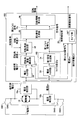
- FIG. 1 is a schematic diagram illustrating a configuration example of a rotation angle detector 100 according to an embodiment of the present invention.
- the rotation angle detector 100 is a device that detects the rotation angle of the electric motor 10.
- the rotation angle detector 100 detects the rotation angle of the electric motor 10 based on the voltage V between the terminals of the electric motor 10 and the current Im flowing through the electric motor 10.
- the electric motor 10 is a DC commutator motor provided with a commutator.
- the electric motor 10 is used, for example, for raising and lowering the window of an automobile, adjusting the angle of a door mirror, adjusting the air flow rate in an air conditioner, adjusting the optical axis of a headlight, and the like.
- FIG. 2 is a schematic diagram of the commutator 20.
- the commutator 20 includes eight commutator pieces 20a separated from each other by slits 20s.
- the slit angle ⁇ c which is the central angle of the arc of each commutator piece 20a, is about 45 degrees.
- the electric motor 10 is connected to a power source through four switches SW1 to SW4.
- the switch SW1 and the switch SW3 are configured to rotate forward clockwise when the switch SW1 and the switch SW3 are closed, and to rotate counterclockwise when the switch SW2 and switch SW4 are closed. .
- the current flowing through the forward rotating motor 10 has a positive value
- the current flowing through the reverse rotating motor 10 has a negative value
- the switch SW2 and the switch SW3 are closed, the current flowing through the forward rotating motor 10 has a negative value
- the current flowing through the reverse rotating motor 10 has a positive value.
- the electric motor 10 and the current detection unit 10b exist in a closed loop.
- the electric resistance value of the electric motor 10 is sufficiently large, even if the two terminals of the electric motor 10 are short-circuited, the electric motor 10 rotates with inertia.
- the electric resistance value is small, the electric motor 10 rapidly decelerates when the two terminals of the electric motor 10 are short-circuited.
- a closed loop that passes through the resistor may be formed.
- the voltage detector 10a detects the voltage V between the terminals of the electric motor 10.
- the current detection unit 10 b detects the current Im flowing through the electric motor 10.
- the rotation angle detector 100 mainly includes a voltage filter unit 30, a rotation angular velocity calculation unit 31, a rotation angle calculation unit 32, a current filter unit 33, a first signal generation unit 34, a second signal generation unit 35, and a rotation information calculation unit. 36, elements such as a failure detection unit 38 are included. Each element may be configured by an electric circuit or may be configured by software.
- the voltage filter unit 30 smoothes the waveform of the inter-terminal voltage V output from the voltage detection unit 10a.
- the voltage filter unit 30 smoothes the waveform of the voltage V between the terminals so that the rotation angular velocity calculation unit 31 can accurately calculate the rotation angular velocity of the electric motor 10.
- the voltage filter unit 30 is a low-pass filter, and outputs an inter-terminal voltage V ′ from which a high-frequency component in the waveform of the inter-terminal voltage V output by the voltage detection unit 10 a is removed as noise.
- the rotation angular velocity calculation unit 31 calculates the rotation angular velocity of the electric motor 10 based on the voltage V ′ between the terminals of the electric motor 10 and the current Im flowing through the electric motor 10. In the example of FIG. 1, the rotational angular velocity calculation unit 31 calculates the rotational angular velocity ⁇ based on Expression (1).
- Ke is a counter electromotive voltage constant
- Rm is an internal resistance of the electric motor 10
- Lm is an inductance of the electric motor 10
- dIm / dt is a single derivative of the current Im.
- the single differentiation of the current Im is, for example, the difference between the previous value of the current Im and the current value of the current Im.
- the rotation angular velocity calculation unit 31 calculates the rotation angular velocity ⁇ of the electric motor 10 at a constant control cycle, and outputs the calculated rotation angular velocity ⁇ to the rotation angle calculation unit 32.
- the rotation angle calculation unit 32 calculates the rotation angle of the electric motor 10.
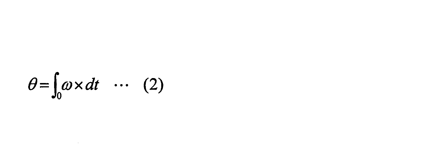
- the rotation angle calculation unit 32 calculates the rotation angle ⁇ based on Expression (2).
- the rotation angle calculation unit 32 calculates the rotation angle ⁇ by accumulating the rotation angular velocity ⁇ output by the rotation angular velocity calculation unit 31 at every constant control cycle, and outputs a rotation angle signal that is a signal related to the calculated rotation angle ⁇ . Output to the second signal generator 35.
- the rotation angle calculation unit 32 resets the rotation angle ⁇ to zero according to the synchronization command from the second signal generation unit 35.
- the current filter unit 33 outputs a ripple component Ir that is a specific frequency component included in the current Im output from the current detection unit 10b.
- the current filter unit 33 constitutes a ripple detection unit RD.
- the current filter unit 33 is configured by, for example, a bandpass filter that passes the frequency of the ripple component Ir so that the first signal generation unit 34 can detect the ripple component Ir of the current Im.
- the current filter unit 33 configured by a band-pass filter removes frequency components other than the ripple component Ir from the waveform of the current Im output from the current detection unit 10b.
- the ripple component Ir used in the present embodiment is generated due to contact / separation between the commutator piece 20a and the brush. Therefore, the angle at which the electric motor 10 rotates during one cycle of the ripple component Ir is equal to the slit-to-slit angle ⁇ c.
- the first signal generation unit 34 generates a signal estimated from the waveform of the ripple component Ir that the electric motor 10 has rotated by a certain angle. This signal is a signal corresponding to the period of the ripple component Ir.
- the fixed angle may be an angle corresponding to one cycle of the ripple component Ir or an angle corresponding to a half cycle.
- a signal (first pulse signal Pa) estimated from the waveform of the ripple component Ir is generated.
- the first signal generation unit 34 constitutes a ripple detection unit RD.
- the first signal generation unit 34 generates the first pulse signal Pa based on the waveform of the ripple component Ir output from the current filter unit 33.
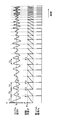
- FIG. 3A is a diagram illustrating an example of timing at which the first signal generation unit 34 generates the first pulse signal Pa.
- the first signal generator 34 generates a first pulse signal Pa for each cycle of the ripple component Ir.
- the first pulse signal Pa is generated every time the ripple component Ir exceeds the reference current value Ib.
- the first pulse signal Pa is generated at times t1, t2, t3,. T1, T2, T3,..., Tn, etc. indicate the period of the ripple component Ir, and the first signal generator 34 generates the first pulse signal for ⁇ 1, ⁇ 2, ⁇ 3,. Shows the rotation angle ⁇ .
- the rotation angle ⁇ is a value calculated by the rotation angle calculation unit 32.
- the first signal generator 34 typically includes the first pulse signal Pa every time the rotation angle ⁇ increases by the slit-to-slit angle ⁇ c, that is, when the rotation angular velocity ⁇ is not zero. Is generated.
- the first signal generation unit 34 typically does not generate the first pulse signal Pa when the rotation angle ⁇ continues to be zero, that is, when the rotation angular velocity ⁇ continues to be zero.
- the first signal generator 34 cannot detect the ripple component Ir and detect the first pulse signal Pa, for example, when the current Im and its ripple component Ir become small during the inertia rotation period after the motor 10 is powered off. May not be generated.
- the first signal generation unit 34 may erroneously generate the first pulse signal Pa according to the inrush current. Such generation omission or erroneous generation of the first pulse signal Pa reduces the reliability of information related to the rotation of the electric motor 10 output by the rotation angle detector 100 (hereinafter referred to as “rotation information”).
- the second signal generation unit 35 can generate a signal representing the rotation angle of the electric motor 10 with higher accuracy.
- the second signal generation unit 35 generates a signal indicating that the electric motor 10 has rotated by a predetermined angle. For example, the second signal generation unit 35 generates the second pulse signal for each inter-slit angle ⁇ c based on the rotation angle signal output from the rotation angle calculation unit 32 and the first pulse signal Pa output from the first signal generation unit 34. Pb is generated.
- the second pulse signal Pb is an example of information indicating that the electric motor 10 has rotated by a predetermined angle. Since the first pulse signal Pa is a signal estimated from only the waveform of the ripple component Ir, it may be erroneously output. On the other hand, since the second pulse signal Pb is a signal estimated from both the first pulse signal Pa and the rotation angle signal, the error can be reduced to a certain value or less.
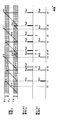
- FIG. 4 is a diagram illustrating an example of timing at which the second signal generation unit 35 generates the second pulse signal Pb.
- the first threshold ⁇ u and the second threshold ⁇ d are thresholds for accepting the first pulse signal Pa, and are set based on, for example, the maximum phase difference between the rotation angle ⁇ and the actual rotation angle of the electric motor 10.
- the second signal generator 35 generates a second pulse based on the first pulse signal Pa generated first by the first signal generator 34 when the rotation angle ⁇ is not less than the first threshold ⁇ u and less than the slit angle ⁇ c.
- a signal Pb is generated.
- the first threshold value ⁇ u may be a preset value or a dynamically set value.
- FIG. 4 shows a reception range, which is an angle range in which the rotation angle ⁇ is greater than or equal to the first threshold ⁇ u and less than the inter-slit angle ⁇ c, as a dot pattern. In the example of FIG.
- the rotation angles ⁇ 1, ⁇ 2, and ⁇ 5 when the first signal generation unit 34 generates the first pulse signals Pa1, Pa2, and Pa4 are equal to or greater than the first threshold ⁇ u and less than the inter-slit angle ⁇ c. That is, the remaining angles until each of the rotation angles ⁇ 1, ⁇ 2, and ⁇ 5 reaches the inter-slit angle ⁇ c is less than the angle ⁇ .
- the angle ⁇ is set based on the maximum error between the rotation angle ⁇ and the actual rotation angle of the electric motor 10.
- the second signal generation unit 35 regards the first pulse signals Pa1, Pa2, and Pa4 generated by the first signal generation unit 34 at times t1, t2, and t5 as not noise.
- the second signal generator 35 generates the second pulse signals Pb1, Pb2, and Pb4 at times t1, t2, and t5.
- the second signal generator 35 outputs a synchronization command to the rotation angle calculator 32. If noise having the same frequency component as the ripple component Ir occurs when the rotation angle ⁇ is less than the slit-to-slit angle ⁇ c and greater than or equal to the first threshold value ⁇ u, an erroneous first pulse signal Pa is output, and the second There is a possibility that the pulse signal Pb is generated.
- the true ripple component Ir is detected at the next timing, and the rotation angle detector 100 can detect the correct rotation angle. Therefore, the rotation angle detected by the rotation angle detector 100 returns to the correct rotation angle even if it is temporarily detected by noise due to noise. Further, the error range is less than the angle ⁇ , and there is no practical problem.
- the second signal generation unit 35 generates the second pulse signal Pb when the rotation angle ⁇ reaches a predetermined angle.
- the predetermined angle is, for example, the slit-to-slit angle ⁇ c.
- the rotation angle ⁇ is an angle calculated by the rotation angle calculation unit 32 and includes an error.
- the second pulse signals Pb3, Pb5, and Pb6 are generated when the absolute values of the rotation angles ⁇ 3, ⁇ 7, and ⁇ 9 reach the inter-slit angle ⁇ c at times t3, t7, and t9.
- the second signal generator 35 outputs a synchronization command to the rotation angle calculator 32.
- the rotation angle calculation unit 32 resets the rotation angle ⁇ to zero.
- the second signal generation unit 35 generates the second pulse signal Pb2 and then does not receive the first pulse signal Pa, so that the absolute value of the rotation angle ⁇ is the slit-to-slit angle.
- the second pulse signal Pb3 is generated.
- the second signal generation unit 35 determines that the absolute value of the rotation angle ⁇ calculated by the rotation angle calculation unit 32 is the angle between the slits. As long as ⁇ c is reached, the second pulse signal Pb is generated. Therefore, generation omission of the first pulse signal Pa can be reliably prevented.
- the second signal generator 35 does not generate the second pulse signal Pb when the rotation angle ⁇ when the first signal generator 34 generates the first pulse signal Pa is less than the second threshold ⁇ d.
- the second threshold value ⁇ d may be a preset value or a dynamically set value. Such a situation typically occurs after the second pulse signal Pb is generated due to the rotation angle ⁇ reaching a predetermined angle.
- FIG. 4 shows a reception range, which is an angle range in which the rotation angle ⁇ is greater than or equal to zero and less than the second threshold value ⁇ d, with a dot pattern. In the example of FIG.
- the first signal generator 34 performs the first pulse.
- a signal Pa3 is generated.
- the rotation angle ⁇ 4 at this time is less than the second threshold value ⁇ d. That is, the rotation angle ⁇ 4 integrated after being reset at time t3 is still less than the angle ⁇ .
- the second signal generation unit 35 can determine that the first pulse signal Pa3 generated by the first signal generation unit 34 at time t4 can be integrated with the second pulse signal Pb3 generated at time t3.
- the second pulse signal Pb3 is generated because the rotation angle ⁇ calculated by the rotation angle calculation unit 32 has reached the inter-slit angle ⁇ c even though the actual rotation angle has not reached the inter-slit angle ⁇ c. Occurs when.
- the time when the first pulse signal Pa3 is generated immediately after the generation of the second pulse signal Pb3 is the moment when the actual rotation angle reaches the inter-slit angle ⁇ c. For this reason, the second signal generation unit 35 outputs a synchronization command to the rotation angle calculation unit 32 when the first pulse signal Pa3 is generated.
- the second signal generator 35 does not generate the second pulse signal Pb at time t4.
- a broken-line arrow toward “x” in FIG. 4 indicates that the second pulse signal Pb is not generated based on the first pulse signal Pa3. The same applies to the broken-line arrow toward “X” in the other drawings.
- the first signal generation unit 34 may generate the first pulse signal Pa continuously in a short time. As described above, in FIG. 3A, every time the ripple component Ir exceeds the reference current value Ib, the first signal generation unit 34 generates the first pulse signal Pa. Immediately before and immediately after the ripple component Ir exceeds the reference current value Ib, the first pulse signal Pa is erroneously generated even if minute noise is superimposed. In this case, the interval at which the first signal generator 34 generates the first pulse signal Pa is less than the angle ⁇ (second threshold ⁇ d). In the example of FIG. 4, the first signal generation unit 34 generates the first pulse signal Pa2 at time t2.
- the second signal generator 35 generates the second pulse signal Pb2 and outputs a synchronization command to the rotation angle calculator 32.
- the rotation angle calculation unit 32 resets the rotation angle ⁇ .
- the first signal generator 34 generates the first pulse signal Pa2 ′ at time t2 ′.
- the rotation angle ⁇ at time t2 ′ is less than the second threshold value ⁇ d.
- the second signal generator 35 does not generate the second pulse signal Pb and does not output a synchronization command.
- a broken-line arrow toward “x” in FIG. 4 indicates that the second pulse signal Pb is not generated based on the first pulse signal Pa3.
- any of the first pulse signals Pa generated continuously in a short time reaches the inter-slit angle ⁇ c. It cannot be determined whether the first pulse signal Pa indicates that the operation has been performed. However, in this case, since the plurality of first pulse signals Pa are generated within a short period (less than the angle ⁇ ), the rotation angle ⁇ reached the inter-slit angle ⁇ c at the time of the first first pulse signal Pa. Even if it is considered, there is no problem in practical use. Further, even if the same noise occurs every time the ripple component Ir exceeds the reference current value Ib, the error is suppressed to less than the angle ⁇ . That is, no error is accumulated. For this reason, it is possible to suppress the error within a range where there is no practical problem.
- the second signal generation unit 35 is configured so that the rotation angle ⁇ when the first signal generation unit 34 generates the first pulse signal Pa is greater than or equal to the second threshold ⁇ d and less than the first threshold ⁇ u, that is, the rotation angle.
- ⁇ is within the angle range R1
- the second pulse signal Pb is not generated, and a synchronization command is not output to the rotation angle calculation unit 32.
- the rotation angle ⁇ 6 when the first signal generation unit 34 generates the first pulse signal Pa5 at time t6 is equal to or greater than the second threshold ⁇ d and less than the first threshold ⁇ u.
- the second signal generation unit 35 can determine that the first pulse signal Pa5 is based on noise. Therefore, the second signal generation unit 35 does not generate the second pulse signal Pb at time t6 and does not output a synchronization command to the rotation angle calculation unit 32. That is, the influence of the first pulse signal Pa5 based on noise can be eliminated.
- the second signal generator 35 does not generate the second pulse signal Pb when the rotation angle ⁇ when the first signal generator 34 generates the first pulse signal Pa is less than the second threshold ⁇ d. However, when the rotation angle ⁇ when the first signal generation unit 34 generates the first pulse signal Pa is less than the second threshold ⁇ d, the second signal generation unit 35 issues a synchronization command to the rotation angle calculation unit 32. There are cases where it is output and there is a case where a synchronization command is not output.
- the two-signal generation unit 35 sends a synchronization command to the rotation angle calculation unit 32.
- a plurality of first pulse signals Pa are generated when the rotation angle ⁇ is less than the second threshold ⁇ d. Then, the second and subsequent first pulse signals Pa are ignored. That is, the second signal generator 35 does not output a synchronization command.
- the second pulse signal Pa is generated.
- the signal generator 35 does not output a synchronization command. That is, when a plurality of first pulse signals Pa are generated while the first pulse signal Pa is less than the second threshold ⁇ d (angle ⁇ ), the second and subsequent first pulse signals Pa are ignored. That is, the second signal generator 35 does not output a synchronization command.
- the rotation angle ⁇ 4 ′ when the first signal generation unit 34 generates the first pulse signal Pa3 ′ at time t4 ′ is less than the second threshold ⁇ d.
- the first pulse signal Pa3 ′ is the second first pulse signal Pa after the most recent second pulse signal Pb3 is generated. Therefore, when receiving the first pulse signal Pa3 ′, the second signal generation unit 35 does not generate the second pulse signal Pb and does not output a synchronization command to the rotation angle calculation unit 32.
- the rotation angle detector 100 can suppress the detection error of the rotation angle ⁇ of the electric motor 10 within a practically acceptable range. In particular, the rotation angle detector 100 does not accumulate errors. For this reason, regardless of the rotation speed of the electric motor 10, the error can be suppressed within a certain range.
- the inventor discovered that the following premise is satisfied, and invented the rotation angle detector 100 described above. (1) The erroneous detection of the ripple component Ir due to minute noise is limited to just before or immediately after the ripple component Ir exceeds the reference current value Ib. In this case, the erroneous first pulse signal Pa is generated only for a short time before and after the correctly generated first pulse signal Pa (from before the angle ⁇ to after the angle ⁇ ).
- the second signal generation unit 35 reduces the current Im and its ripple component Ir during the inertia rotation period after the power of the motor 10 is turned off, and the first signal generation unit 34 has a waveform of the ripple component Ir. Even if the first pulse signal Pa cannot be generated based on the second pulse signal Pb, the second pulse signal Pb can be generated.
- the second signal generation unit 35 for example, generates an inrush current immediately after the motor 10 is turned on, and the first signal generation unit 34 erroneously generates the first pulse signal Pa according to the inrush current. Even in this case, the second pulse signal Pb corresponding to the first pulse signal Pa is not generated. That is, the influence of the first pulse signal Pa can be eliminated.
- the second signal generation unit 35 generates the first pulse signal Pa even if the first signal generation unit 34 erroneously generates the first pulse signal Pa due to noise or the like.
- the corresponding second pulse signal Pb is not generated, and a synchronization command is not output to the rotation angle calculation unit 32.
- the rotation angle detector 100 calculates the rotation information of the motor 10 based on the second pulse signal Pb generated based on both the first pulse signal Pa and the rotation angle signal. Reliability can be improved.
- the second signal generator 35 outputs a direction signal indicating the rotation direction of the electric motor 10.
- the second signal generation unit 35 outputs a positive value as the rotation angle ⁇ if the rotation direction is the forward rotation direction, and outputs a negative value as the rotation angle ⁇ if the rotation direction is the reverse rotation direction.
- the rotation angle ⁇ has a positive value when the current flowing through the electric motor 10 is a positive value, and has a negative value when the current flowing through the electric motor 10 is a negative value.
- the rotation angle ⁇ has a positive value when the current flowing through the electric motor 10 has a negative value, and has a negative value when the current flowing through the electric motor 10 has a positive value.
- the rotation information calculation unit 36 calculates rotation information of the electric motor 10.
- the rotation information of the electric motor 10 includes, for example, a rotation amount (rotation angle) from the reference rotation position, a rotation number from the reference rotation position, and the like.
- the rotation information of the electric motor 10 may be a value converted into the relative position of the upper edge of the window with respect to the reference position, the opening amount of the window, or the like.
- statistical values such as an average value, maximum value, minimum value, and intermediate value of the rotational angular velocity ⁇ in a certain period may be included.
- the rotation information calculation unit 36 calculates rotation information of the electric motor 10 based on the output of the second signal generation unit 35.
- the amount of rotation after the rotation of the electric motor 10 is calculated by multiplying the number of second pulse signals Pb generated after the rotation of the electric motor 10 is multiplied by the inter-slit angle ⁇ c.
- the rotation information calculation unit 36 determines whether to increment or decrement the number of second pulse signals Pb based on the direction signal output together with the second pulse signal Pb by the second signal generation unit 35.
- the rotation information calculation unit 36 separately counts the number of second pulse signals Pb received together with the direction signal representing the forward rotation direction and the number of second pulse signals Pb received together with the direction signal representing the reverse rotation direction. Then, the rotation amount of the electric motor 10 may be calculated based on the difference between them.
- the failure detection unit 38 detects a failure of the rotation angle detector 100.
- the failure detection unit 38 determines whether or not the outputs of the voltage detection unit 10a, the current detection unit 10b, and the ripple detection unit RD as detection targets indicate normal rotation. The failure of each of the current detection unit 10b and the ripple detection unit RD is detected. When a failure is detected, a failure detection signal is output to the outside.
- the failure detection unit 38 has an abnormal state where, for example, two outputs of the voltage detection unit 10a, the current detection unit 10b, and the ripple detection unit RD indicate normal rotation and the remaining one output does not indicate normal rotation. If it continues for a predetermined period, it is determined that the remaining one has failed.
- the failure detection unit 38 is, for example, a first abnormal state in which the output of the voltage detection unit 10a indicates normal rotation, the output of the current detection unit 10b indicates normal rotation, and the output of the ripple detection unit RD does not indicate normal rotation. Is continued for a predetermined period, it is determined that the ripple detection unit RD has failed.
- the ripple detector RD In the first abnormal state, for example, the ripple detector RD outputs the first pulse signal Pa even though the rotational angular velocity ⁇ calculated based on the outputs of the voltage detector 10a and the current detector 10b is not zero. It is not in the state.
- the normal ranges of the current Im, the period T, and the voltage V between terminals are set in advance in a nonvolatile storage medium or the like, but may be calculated or set dynamically.
- the normal range is a normal range during normal rotation of the electric motor 10 (hereinafter referred to as “first normal range”).
- first normal range The normal range when the electric motor 10 is stopped is not included.
- the failure detection unit 38 is, for example, within a voltage value range when the output of the voltage detection unit 10a is normal rotation, and out of a current value range when the output of the current detection unit 10b is normal rotation, In addition, when the second abnormal state in which a signal indicating normal rotation is output from the ripple detection unit RD continues for a predetermined period, it is determined that the current detection unit 10b has failed.
- the current Im is first normal even though the inter-terminal voltage V is in the first normal range and the cycle T of the first pulse signal Pa is in the first normal range. It is out of range.
- the magnitude of the current Im within the normal range is, for example, less than the magnitude of the stall current value.
- the stall current value is calculated, for example, by multiplying a value obtained by dividing the inter-terminal voltage V by the internal resistance Rm by a coefficient K1.
- the coefficient K1 may be a fixed value or a variable value.
- the failure detection unit 38 is, for example, outside the voltage value range when the output of the voltage detection unit 10a is normal rotation, and within the current value range when the output of the current detection unit 10b is normal rotation, In addition, when the third abnormal state in which a signal indicating normal rotation is output from the ripple detection unit RD continues for a predetermined period, it is determined that the voltage detection unit 10a has failed.
- the third abnormal state is, for example, in spite of the current Im being in the first normal range and the period T of the first pulse signal Pa output from the ripple detector RD being in the first normal range. This is a state in which the voltage V is outside the first normal range.
- the failure detection unit 38 has a timer unit 38T that measures the duration of the abnormal state as the determination suspension time.
- the determination hold time means a time for holding the determination that the detection target is broken.
- the failure detection unit 38 determines that one detection target that has output different from the normal rotation in the abnormal state is defective. To do.
- FIG. 5 is a flowchart of the rotation amount calculation process.
- the rotation angle detector 100 performs this rotation amount calculation process while the electric motor 10 is being driven.
- the rotation angle detector 100 acquires the inter-terminal voltage V and the current Im (step ST1).
- the rotation angle detector 100 acquires the inter-terminal voltage V output from the voltage detection unit 10a and the current Im output from the current detection unit 10b for each predetermined control cycle.
- the rotation angle detector 100 calculates the rotation angular velocity ⁇ and the rotation angle ⁇ (step ST2).
- the rotation angular velocity calculation unit 31 of the rotation angle detector 100 calculates the rotation angular velocity ⁇ for each predetermined control cycle by substituting the inter-terminal voltage V and the current Im into the equation (1).
- the rotation angle calculation unit 32 of the rotation angle detector 100 calculates the rotation angle ⁇ by integrating the rotation angular velocities ⁇ calculated for each control cycle.
- the rotation angle detector 100 determines whether or not the rotation angle ⁇ is less than a predetermined angle (step ST3).
- the second signal generation unit 35 of the rotation angle detector 100 determines whether or not the rotation angle ⁇ is less than the inter-slit angle ⁇ c.
- the second signal generator 35 determines that the first pulse signal Pa has not been generated at the timing up to the inter-slit angle ⁇ c. . In this case, the second signal generator 35 sets the flag F to “False” to indicate that the first pulse signal Pa is not generated (step ST3A).
- the flag F is a flag for indicating whether or not the first pulse signal Pa is generated. The initial value of the flag F is “False” indicating that the first pulse signal Pa is not generated. The flag F being “True” indicates that the first pulse signal Pa has already been generated.
- the second pulse signal Pb is generated (step ST10), and the rotation angle ⁇ is reset to zero (step ST11).
- the rotation angle ⁇ is the rotation angles ⁇ 3, ⁇ 7 at the times t3, t7, t9. , ⁇ 9 is reached.
- the second signal generator 35 determines whether or not the first pulse signal Pa is generated (step ST4). . In the example of FIG. 1, it is determined whether or not the first pulse signal Pa is generated by the first signal generation unit 34.
- the rotation angle is detected.
- the device 100 calculates the rotation amount (step ST7).
- the rotation information calculation unit 36 calculates the rotation amount of the electric motor 10 based on the output of the second signal generation unit 35. In this case, there is no change in the calculated rotation amount. This corresponds to the case where the rotation angle ⁇ is the rotation angle ⁇ 0 at time t0 in the example of FIG.
- the rotation angle detector 100 determines whether or not the rotation angular velocity ⁇ has become zero (step ST8).
- the rotation angle detector 100 determines that the rotation angular velocity ⁇ is not zero (NO in step ST8)
- the rotation angle detector 100 returns the process to step ST1 and determines that the rotation angular velocity ⁇ is zero (step ST8). YES), the rotation amount calculation process is terminated.
- the second signal generation unit 35 determines whether or not the rotation angle ⁇ is less than the first threshold ⁇ u (step ST5). This is because the first pulse signal Pa generated at a timing less than the first threshold ⁇ u is highly likely to be based on noise.
- the second signal generator 35 sets the flag F to “True” to indicate whether or not the first pulse signal Pa has been generated. (Step ST5A). Then, the second signal generator 35 generates the second pulse signal Pb (step ST10), and resets the rotation angle ⁇ to zero (step ST11). This is because when the first pulse signal Pa is generated when the rotation angle ⁇ is equal to or greater than the first threshold ⁇ u, the actual rotation angle at the time when the first pulse signal Pa is generated is close to the inter-slit angle ⁇ c. This corresponds to the case where the first pulse signals Pa1, Pa2, Pa4 are generated at times t1, t2, t5 in the example of FIG.
- the second signal generator 35 cannot determine at this time that the first pulse signal Pa is not based on noise.
- the rotation angle ⁇ may include some error.
- the generation timing of the first pulse signal Pa may be slightly shifted due to noise or the like. For this reason, the time when the rotation angle ⁇ reaches the slit-to-slit angle ⁇ c may be different from the time when the first pulse signal Pa is generated. For this reason, it is because it is not known which is earlier, the time when the rotation angle ⁇ reaches the inter-slit angle ⁇ c or the time when the first pulse signal Pa is generated. Therefore, the second signal generator 35 determines whether or not the rotation angle ⁇ is less than the second threshold ⁇ d with respect to the first pulse signal Pa received first after generating the latest second pulse signal Pb. (Step ST6).
- the second signal generation unit 35 checks the flag F (step ST6A).
- the flag F is a flag for determining that the first pulse signal Pa is continuously generated.
- the flag F is “True”
- the first pulse signal Pa is the second and subsequent first pulse signals Pa generated continuously.
- the rotation angle detector 100 calculates the rotation amount (step ST7). This corresponds to the case where the first pulse signals Pa2 ′ and Pa3 ′ are generated at times t2 ′ and t4 ′ in the example of FIG.
- the second signal generation unit 35 sets the flag F to “True” (step ST6B). Thereafter, the second signal generation unit 35 resets the rotation angle ⁇ to zero (step ST11). This is because when the rotation angle ⁇ is less than the second threshold ⁇ d, the actual rotation angle when the first pulse signal Pa is generated is close to the inter-slit angle ⁇ c. That is, when it is less than the second threshold ⁇ d, it can be determined that the first pulse signal Pa corresponds to the second pulse signal Pb generated immediately before. This corresponds to the case where the first pulse signals Pa3 and Pa6 are generated at times t4 and t8 in the example of FIG. That is, it can be determined that the first pulse signals Pa3 and Pa6 correspond to the second pulse signals Pb3 and Pb5.
- the second signal generation unit 35 When it is determined that the rotation angle ⁇ related to the first first pulse signal Pa is equal to or larger than the second threshold ⁇ d (NO in step ST6), that is, when it is determined that the rotation angle ⁇ is within the angle range R1, the second signal generation unit 35 Then, it is determined that the first pulse signal Pa is based on noise. In this case, the second signal generator 35 does not generate the second pulse signal Pb and does not reset the rotation angle ⁇ . Then, the rotation information calculation unit 36 calculates the rotation amount of the electric motor 10 based on the output of the second signal generation unit 35. This corresponds to the case where the first pulse signal Pa5 is generated at time t6 in the example of FIG. That is, the second signal generation unit 35 determines that the first pulse signal Pa5 is based on noise.
- the rotation angle detector 100 calculates the rotation amount of the electric motor 10 (step ST7).
- the rotation information calculation unit 36 of the rotation angle detector 100 multiplies the number of second pulse signals Pb generated after the rotation of the electric motor 10 is multiplied by the inter-slit angle ⁇ c. The amount of rotation after the start of rotation is calculated.
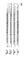
- FIG. 6 is a diagram showing transitions of the composite pulse signal and the hall pulse signal.
- the synthesized pulse signal is a signal obtained by synthesizing a plurality of pulses of the second pulse signal Pb into one pulse.
- the slit-to-slit angle ⁇ c is 90 degrees.
- the first pulse signal Pa and the second pulse signal Pb are basically generated every time the rotating shaft of the electric motor 10 rotates 90 degrees.
- the synthesized pulse signal is generated by synthesizing two pulses of the second pulse signal Pb into one pulse. That is, the rotation angle detector 100 is configured to generate one composite pulse signal each time the rotation shaft of the electric motor 10 rotates 180 degrees.
- the hall pulse signal is a pulse signal output from the hall sensor.
- the hall sensor detects a magnetic flux generated by a magnet attached to the rotating shaft of the electric motor 10 for comparison between the second pulse signal Pb and the hall pulse signal.
- the rotation angle detector 100 is configured to generate one Hall pulse signal each time the rotation shaft of the electric motor 10 rotates 180 degrees.
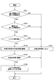
- FIG. 7 is a flowchart of the failure detection process.
- the failure detection unit 38 repeatedly executes this failure detection process at a predetermined control cycle.
- the failure detection unit 38 determines whether two of the outputs of the three detection targets indicate normal rotation and the other one does not indicate normal rotation (step ST11). That is, it is determined whether or not the three detection targets are in an abnormal state.
- the three detection targets are a voltage detection unit 10a, a current detection unit 10b, and a ripple detection unit RD.
- the terminal voltage V which is the output of the voltage detection unit 10a, is typically greater than, for example, a predetermined lower limit voltage value (for example, 7 [V]) and smaller than a predetermined upper limit voltage value (for example, 18 [V]). It is determined that rotation is indicated, and otherwise it is determined that normal rotation is not indicated.
- a predetermined lower limit voltage value for example, 7 [V]
- a predetermined upper limit voltage value for example, 18 [V]
- the current Im that is the output of the current detection unit 10b is larger than a predetermined lower limit current value (for example, 0.5 [A]) and smaller than a predetermined upper limit current value (for example, 20 [A]). It is determined that normal rotation is indicated, and otherwise it is determined that normal rotation is not indicated.
- the upper limit current value may be a stall current value.
- the first pulse signal Pa which is the output of the ripple detection unit RD, is determined to indicate normal rotation when, for example, the period T is greater than a predetermined lower limit period and smaller than a predetermined upper limit period, and otherwise It is determined that normal rotation is not indicated.
- the failure detection unit 38 When it is determined that the three detection targets are in an abnormal state (YES in step ST11), the failure detection unit 38 starts measuring the determination hold time (step ST12). If measurement of the judgment hold time has already been started, the measurement is continued. In the present embodiment, the failure detection unit 38 starts or continues timing by the timer unit 38T.
- the failure detection unit 38 determines whether or not the determination hold time exceeds a threshold (step ST13).
- the threshold may be different or may be the same depending on which of the three detection targets is determined not to exhibit normal rotation.
- the failure detection unit 38 determines that the remaining one detection target for which it is determined that the output does not indicate normal rotation has failed. (Step ST14). At this time, the failure detection unit 38 may output a failure detection signal to the outside.
- the failure detection unit 38 performs the current failure detection process without determining that the remaining one detection target is defective. Terminate. That is, until it is determined that the determination hold time exceeds the threshold, the determination that one of the detection targets is out of order is suspended. This is to prevent erroneous detection of failure.
- the failure detection unit 38 If it is determined that the three detection targets are not in an abnormal state (NO in step ST11), the failure detection unit 38 resets the determination suspension time (step ST15). In the present embodiment, the failure detection unit 38 resets the determination suspension time to zero and then stops the time measurement by the timer unit 38T.
- the failure detection unit 38 determines that an abnormal state different from the previous abnormal state has occurred, the failure detection unit 38 resets the determination suspension time to zero and restarts the time measurement by the timer unit 38T. For example, even if a certain amount of time has already been counted up since the first abnormal state is determined, the first abnormal state is resolved and the second abnormal state before the determination suspension time exceeds the threshold value. If it is determined that the state has been reached, the determination suspension time relating to the first abnormal state is reset to zero, and the timer unit 38T starts counting the determination suspension time relating to the second abnormal state.
- the rotation angle detector 100 a state in which two of the voltage detection unit 10a, the current detection unit 10b, and the ripple detection unit RD indicate normal rotation and the remaining one does not indicate normal rotation continues for a predetermined time. If it does, it can be determined that the remaining one has failed.
- FIG. 8 is a flowchart of the first failure detection process.
- the failure detection unit 38 repeatedly executes this first failure detection process at a predetermined control cycle.
- the failure detection unit 38 determines whether or not the inter-terminal voltage V is within the first normal range (step ST21). And when it determines with the voltage V between terminals being in a 1st normal range (YES of step ST21), it is determined whether the electric current Im is in a 1st normal range (step ST22). If it is determined that the current Im is within the first normal range (YES in step ST22), it is determined whether or not a ripple is detected (“no ripple detection” or “with ripple detection”) ( Step ST23).
- the failure detection unit 38 starts measuring the non-detection time (step ST24).
- the non-detection time is an example of the determination suspension time, and represents a time when no ripple is detected. If measurement of the non-detection time has already started, the measurement is continued.
- the failure detection unit 38 determines whether or not the non-detection time exceeds a threshold value (step ST25).
- the threshold is desirably a period longer than the inertial rotation period. This is to prevent the ripple detection unit RD from being erroneously determined to be faulty based on the state of no ripple detection during inertial rotation.
- the failure detection unit 38 determines that the ripple detection unit RD has failed (step ST26). At this time, the failure detection unit 38 may output a failure detection signal regarding the failure of the ripple detection unit RD to the outside.
- the failure detection unit 38 ends the first failure detection process of this time without determining that the ripple detection unit RD has failed. Let That is, until it is determined that the non-detection time exceeds the threshold, the determination that the ripple detection unit RD is out of order is suspended. This is to prevent erroneous detection of failure.
- the failure detection part 38 When it is determined that the inter-terminal voltage V is not within the first normal range (NO in step ST21), when it is determined that the current Im is not within the first normal range (NO in step ST22), or there is ripple detection When it determines (NO of step ST23), the failure detection part 38 resets non-detection time (step ST27). In the present embodiment, the failure detection unit 38 resets the non-detection time to zero and then stops measuring the non-detection time. Note that the three determinations from step ST21 to step ST23 are out of order, and the three determinations may be performed simultaneously.
- the failure detection unit 38 can determine that the electric motor 10 is rotating from the voltage V between the terminals and the current Im, and the first pulse signal Pa is not detected even after a predetermined period has elapsed, the ripple is detected. It can be determined that the detection unit RD is out of order.
- FIG. 9 is a flowchart of the second failure detection process.
- the failure detection unit 38 repeatedly executes the second failure detection process at a predetermined control cycle.
- the failure detection unit 38 determines whether or not a ripple is detected as in normal rotation (step ST31).
- the state in which the ripple is detected as in the normal rotation is, for example, a state in which the period T of the first pulse signal Pa output from the ripple detection unit RD is less than a predetermined value.
- step ST31 If it is determined that the ripple is detected as in the normal rotation (YES in step ST31), it is determined whether or not the inter-terminal voltage V is within the first normal range (step ST32). If it is determined that the inter-terminal voltage V is within the first normal range (YES in step ST32), it is determined whether or not the current Im is outside the first normal range (step ST33).
- the failure detection unit 38 starts measuring the current abnormality duration time.
- the current abnormality continuation time is an example of the determination suspension time, and represents the time during which the state where the current Im is outside the first normal range continues. If the measurement of the current abnormality duration has already been started, the measurement is continued.
- the failure detection unit 38 determines whether or not the current abnormality continuation time exceeds the threshold (step ST35).
- the threshold value is desirably a period longer than the period required for one rotation of the motor 10 during inertial rotation. This is to prevent the current detection unit 10b from being erroneously determined to be out of order based on noise included in the current Im.
- the failure detection unit 38 determines that the current detection unit 10b has failed (step ST36). At this time, the failure detection unit 38 may output a failure detection signal regarding the failure of the current detection unit 10b to the outside.
- the failure detection unit 38 When it is determined that the current abnormality continuation time does not exceed the threshold value (NO in step ST35), the failure detection unit 38 performs the second failure detection process this time without determining that the current detection unit 10b has failed. Terminate. That is, until it is determined that the current abnormality continuation time exceeds the threshold, the determination that the current detection unit 10b is out of order is suspended. This is to prevent erroneous detection of failure.
- the failure detection unit 38 resets the current abnormality continuation time (step ST37). In the present embodiment, the failure detection unit 38 resets the current abnormality duration time to zero and then stops measuring the current abnormality duration time. Note that the three determinations from step ST31 to step ST33 are out of order, and the three determinations may be performed simultaneously.
- the failure detection unit 38 can detect that the ripple is detected and the electric motor 10 is rotating in the same manner as during normal rotation, and the inter-terminal voltage V is within the normal range and the current is maintained for a predetermined period.
- Im is outside the first normal range (for example, zero), it can be determined that the current detection unit 10b has failed.
- FIG. 10 is a flowchart of the third failure detection process.
- the failure detection unit 38 repeatedly executes the third failure detection process at a predetermined control cycle.
- the failure detection unit 38 determines whether or not a ripple is detected as in the normal rotation (step ST41). And when it determines with the ripple being detected similarly to the time of normal rotation (YES of step ST41), it is determined whether the electric current Im is in a 1st normal range (step ST42). If it is determined that the current Im is within the first normal range (YES in step ST42), it is determined whether or not the inter-terminal voltage V is outside the first normal range (step ST43).
- the failure detection unit 38 measures the voltage abnormality duration time. Is started (step ST44).
- the voltage abnormality continuation time is an example of the determination suspension time, and represents the time during which the state where the inter-terminal voltage V is outside the normal range continues. If the measurement of the voltage abnormality duration has already started, the measurement is continued.
- failure detection unit 38 determines whether or not the voltage abnormality duration has exceeded a threshold (step ST45).
- the threshold value is desirably a period longer than the period required for one rotation of the motor 10 during inertial rotation. This is to prevent erroneous determination that the voltage detection unit 10a is out of order based on noise included in the inter-terminal voltage V.
- the failure detection unit 38 determines that the voltage detection unit 10a has failed (step ST46). At this time, the failure detection unit 38 may output a failure detection signal regarding the failure of the voltage detection unit 10a to the outside.
- the failure detection unit 38 When it is determined that the voltage abnormality continuation time does not exceed the threshold (NO in step ST45), the failure detection unit 38 performs the third failure detection process this time without determining that the voltage detection unit 10a has failed. Terminate. That is, until it is determined that the voltage abnormality duration has exceeded the threshold value, the determination that the voltage detection unit 10a has failed is suspended. This is to prevent erroneous detection of failure.
- the failure detection unit 38 resets the voltage abnormality duration (step ST47). In this embodiment, the failure detection unit 38 resets the voltage abnormality duration to zero and then stops measuring the voltage abnormality duration. Note that the three determinations from step ST41 to step ST43 are out of order, and the three determinations may be performed simultaneously.
- the failure detection unit 38 can detect that the ripple is detected and the electric motor 10 is rotating in the same manner as during normal rotation, and the current Im is within the first normal range and the terminal over a predetermined period.
- the inter-voltage V is outside the first normal range (for example, zero), it can be determined that the voltage detector 10a has failed.
- the rotation angle detector 100 that acquires information related to the rotation of the electric motor 10 including the commutator 20 includes the detection result of the voltage detection unit 10 a that detects the voltage V between the terminals of the electric motor 10, and the electric motor 10.
- a rotation angular velocity calculation unit 31 that calculates a rotation angular velocity ⁇ of the electric motor 10 based on a detection result of the current detection unit 10b that detects the flowing current Im, and a ripple detection unit that detects a ripple component Ir included in the current Im flowing through the electric motor 10.
- the failure detection unit 38 has a predetermined state in which two outputs of the voltage detection unit 10a, the current detection unit 10b, and the ripple detection unit RD indicate normal rotation and the remaining one output does not indicate normal rotation. If it continues for a period of time, it is determined that the remaining one has failed.
- the rotation angle detector 100 includes each of the first pulse signal Pa generated based on the ripple component Ir of the current Im and the rotation angle ⁇ calculated based on the inter-terminal voltage V and the current Im.
- the rotational state of the electric motor 10 can be estimated individually. That is, the rotation state of the electric motor 10 can be estimated separately using the first pulse signal Pa and the rotation angle ⁇ , which are two parameters derived by different methods. Therefore, when the rotational state estimated using the first parameter and the rotational state estimated using the second parameter are significantly different, the detection target related to the derivation of one parameter is out of order. It can be judged. If it can be confirmed that two of the three detection targets are normal, it can be determined that the remaining one is out of order. As a result, a failure to be detected can be detected more reliably without additional cost.
- the rotation angle detector 100 can detect each failure of the three detection targets by determining whether two of the outputs of the three detection targets are normal and the other one is abnormal. Or a configuration capable of detecting a specific two failures of the three detection targets, or a configuration capable of detecting a specific failure of the three detection targets. May be.
- the electric motor with a rotation angle detector includes an electric motor 10 and a rotation angle detector 100 that detects the rotation angle of the electric motor 10.
- the electric motor 10 includes a commutator 20 including a plurality of commutator pieces 20a.
- the rotation angle detector 100 has two outputs of the voltage detection unit 10a, the current detection unit 10b, and the ripple detection unit RD, which are three detection units, exhibit normal rotation, and the remaining one output performs normal rotation. You may have the timer part 38T which measures the continuation period of the state which is not shown. Then, the failure detection unit 38 may determine that the remaining one has failed when the duration measured by the timer unit 38T exceeds a predetermined period. With this configuration, the rotation angle detector 100 can more reliably prevent erroneous detection of a failure.
- the rotation angle detector 100 that acquires rotation information of the electric motor 10 including the commutator 20 includes a rotation angle calculation unit 32 that calculates the rotation angle ⁇ based on the voltage V between the terminals and the current Im, and a current Im.
- a first signal generator 34 that generates a first pulse signal Pa based on the included ripple component Ir, and a second that represents that the motor 10 has rotated by a predetermined angle based on the first pulse signal Pa and the rotation angle ⁇ .
- a second signal generation unit 35 that generates the pulse signal Pb and a rotation information calculation unit 36 that calculates rotation information based on the output of the second signal generation unit 35 are included. Therefore, even if there is no rotation sensor such as a hall sensor, the rotation information of the electric motor 10 can be acquired with high reliability. This means that parts necessary for using a rotation sensor such as a sensor interface circuit and a harness can be omitted. Therefore, weight reduction, cost reduction, size reduction, etc. can be realized.
- the rotation angle detector 100 uses the first pulse signal Pa generated based on the ripple component Ir of the current Im and the rotation angle ⁇ calculated based on the inter-terminal voltage V and the current Im.
- a pulse signal Pb is generated. That is, the second pulse signal Pb is generated using the first pulse signal Pa and the rotation angle ⁇ , which are two parameters derived by different methods. Therefore, even if one parameter is not derived properly, the other parameter can compensate for the problem. As a result, the rotation information of the electric motor 10 can be acquired with higher reliability.
- the rotation angle calculation unit 32 is configured to calculate the rotation angle ⁇ by integrating the rotation angular velocity ⁇ of the electric motor 10 calculated based on the inter-terminal voltage V and the current Im, for example. Therefore, the rotation angle calculation unit 32 can stably and continuously calculate the rotation angle ⁇ over the entire period including the period immediately after the start of the electric motor 10 and the inertia rotation period. And the 2nd signal generation part 35 is constituted so that the 2nd pulse signal Pb may be generated immediately, for example, when rotation angle theta reaches a predetermined angle.
- the second signal generation unit 35 represents that the first pulse signal Pa has been rotated by a predetermined angle based on the rotation angle ⁇ that is stably and continuously calculated even when generation failure of the first pulse signal Pa occurs.
- the second pulse signal Pb can be generated in real time. Therefore, the rotation angle detector 100 can calculate the rotation information of the electric motor 10 without delay.
- the second signal generation unit 35 is configured to output a command to the rotation angle calculation unit 32 to reset the rotation angle ⁇ to zero when the rotation angle ⁇ reaches a predetermined angle, for example. Therefore, the rotation angle detector 100 limits the maximum value of the rotation angle ⁇ calculated by the rotation angle calculation unit 32 to a predetermined angle, so that the memory size necessary for storing the rotation angle ⁇ can be reduced.
- the predetermined angle is, for example, the central angle of the arc of the commutator piece 20a, that is, the slit-to-slit angle ⁇ c. Therefore, the rotation angle detector 100 can set the maximum value of the accumulated error of the rotation angle ⁇ calculated by the rotation angle calculation unit 32 as the inter-slit angle ⁇ c.
- the reception range is, for example, a range of the maximum error of the rotation angle ⁇ that occurs each time the electric motor 10 rotates by the inter-slit angle ⁇ c. That is, when the rotation angular velocity calculation unit 31 calculates the rotation angular velocity ⁇ larger than the actual rotation angle, the first pulse signal Pa based on the actual rotation angle is generated (including an error). Is the second threshold ⁇ d. Further, when the rotational angular velocity calculation unit 31 calculates the rotational angular velocity ⁇ smaller than the actual rotational angle velocity ⁇ , the first pulse signal Pa based on the actual rotational angle is generated (including an error). Is the first threshold value ⁇ u. Therefore, in the rotation angle detector 100, the error of the rotation angle ⁇ calculated by the rotation angle calculation unit 32 is not accumulated. That is, no matter how many times the motor 10 rotates, the error can be in the range of - ⁇ to + ⁇ .
- the second signal generator 35 is configured to generate the second pulse signal Pb when the first pulse signal Pa is received and the rotation angle ⁇ is equal to or greater than the first threshold ⁇ u, for example.
- the first threshold ⁇ u is set in advance as a value smaller than a predetermined angle (inter-slit angle ⁇ c), for example.
- the second signal generation unit 35 regards the first pulse signal Pa generated when the rotation angle ⁇ is equal to or greater than the first threshold ⁇ u as not based on noise. Even if the first pulse signal Pa is not generated, the second pulse signal Pb is generated when the rotation angle ⁇ reaches a predetermined angle (inter-slit angle ⁇ c). Therefore, it is possible to reliably eliminate the influence on the calculation result of the rotation information due to the generation failure of the first pulse signal Pa.
- the second signal generator 35 is configured not to generate the second pulse signal Pb if the rotation angle ⁇ is less than the first threshold ⁇ u when the first pulse signal Pa is received, for example.
- the second signal generation unit 35 can determine that the first pulse signal Pa generated when the rotation angle ⁇ is less than the first threshold ⁇ u is based on noise. And it can prevent generating the 2nd pulse signal Pb corresponding to the 1st pulse signal Pa generated based on noise. Therefore, the influence on the calculation result of the rotation information by the first pulse signal Pa generated based on the noise can be surely eliminated.
- the rotation angle calculation unit 32 issues a command to reset the rotation angle ⁇ to zero.
- the second threshold ⁇ d is set in advance as a value whose phase is delayed by ⁇ from a predetermined angle (inter-slit angle ⁇ c).
Landscapes
- Engineering & Computer Science (AREA)
- Power Engineering (AREA)
- Control Of Direct Current Motors (AREA)
- Transmission And Conversion Of Sensor Element Output (AREA)
Abstract
回転角度検出器(100)は、電圧検出部(10a)及び電流検出部(10b)の検出結果に基づいて電動機(10)の回転角速度(ω)を算出する回転角速度算出部(31)と、電動機(10)を流れる電流(Im)に含まれるリップル成分(Ir)を検出するリップル検出部(RD)と、電圧検出部(10a)、電流検出部(10b)、及び、リップル検出部(RD)のそれぞれの故障を検知する故障検知部(38)とを含む。故障検知部(38)は、電圧検出部(10a)、電流検出部(10b)、及び、リップル検出部(RD)のうちの2つの出力が通常回転を示し且つ残りの1つの出力が通常回転を示さない状態が所定期間にわたって継続した場合に、その残りの1つが故障していると判断する。
Description
本発明は、回転角度検出器付き電動機、電動機の回転角度検出器、及び、電動機の回転角度検出器の故障を検知する方法に関する。
従来、直流電動機の速度を制御する装置が知られている(特許文献1参照。)。この装置は、電源電圧を調整して指令電圧V1に応じた電圧を直流電動機に印加する電圧制御器と、直流電動機の実際の回転速度に比例する検出速度を出力する速度検出器と、直流電動機の電動機電流を増幅して検出電流を出力する電流検出器とを備えている。また、指令電圧、検出速度及び検出電流に基づいて、検出速度が零であるときに、その原因が、速度検出器の故障によるものか、或いは、大きな回転負荷が直流電動機に急激に作用したことによるものかを判定する速度検出異常判定器を備えている。
しかしながら、上述の装置は、直流電動機の端子間電圧を検出していないため、端子間電圧が異常である場合、検出速度が零である原因が速度検出器の故障によるものか否かを誤って判定してしまうおそれがある。また、電流検出器が異常である場合にも、検出速度が零である原因が速度検出器の故障によるものか否かを誤って判定してしまうおそれがある。
上述の点に鑑み、直流整流子電動機の回転に関する情報を取得する装置の故障をより確実に検知することが望まれる。
本発明の実施例に従った装置は、電動機と、前記電動機の回転角度を検出する回転角度検出器とを備え、前記電動機は、複数の整流子片からなる整流子を有し、前記回転角度検出器は、前記電動機の端子間電圧を検出する電圧検出部の検出結果、及び、前記電動機を流れる電流を検出する電流検出部の検出結果に基づいて前記電動機の回転角速度を算出する回転角速度算出部と、前記電動機を流れる電流に含まれるリップル成分を検出するリップル検出部と、前記電圧検出部、前記電流検出部、及び、前記リップル検出部の出力に基づいて前記電圧検出部、前記電流検出部、及び、前記リップル検出部のそれぞれの故障を検知する故障検知部と、を含み、前記故障検知部は、前記電圧検出部、前記電流検出部、及び、前記リップル検出部のうちの2つの出力が通常回転を示し且つ残りの1つの出力が通常回転を示さない状態が所定期間にわたって継続した場合に、該残りの1つが故障していると判断する。
上述の手段により、直流整流子電動機の回転に関する情報を取得する装置の故障をより確実に検知できる。
以下、図を参照し、本発明の実施例に係る回転角度検出器100について説明する。図1は、本発明の実施例に係る回転角度検出器100の構成例を示す概略図である。
回転角度検出器100は、電動機10の回転角度を検出する装置である。図1の例では、回転角度検出器100は、電動機10の端子間電圧Vと電動機10を流れる電流Imとに基づいて電動機10の回転角度を検出する。
電動機10は、整流子を備えた直流整流子電動機である。電動機10は、例えば、自動車のウィンドウの昇降、ドアミラーの角度の調整、空調装置における送風量の調整、ヘッドライトの光軸の調整等で使用される。
図2は整流子20の概略図である。図2に示すように、整流子20は、スリット20sによって互いに隔てられた8つの整流子片20aで構成されている。各整流子片20aの円弧の中心角であるスリット間角度θcは約45度である。
電動機10は、4つのスイッチSW1~SW4を介して電源に接続されている。そして、スイッチSW1とスイッチSW3とが閉状態となったときに時計回りに順回転し、スイッチSW2とスイッチSW4とが閉状態となったときに反時計回りに逆回転するように構成されている。電源に接続されている図1の例では、順回転する電動機10を流れる電流が正の値を有し、逆回転する電動機10を流れる電流が負の値を有する。惰性回転中は、スイッチSW2とスイッチSW3とが閉状態となり、順回転する電動機10を流れる電流は負の値を有し、逆回転する電動機10を流れる電流は正の値を有する。本実施例では、惰性回転中も回転を検出するために、電動機10と電流検出部10bは、閉ループ中に存在する。なお、本実施例では、電動機10は、電気抵抗値が十分大きいため、電動機10の2つの端子を短絡しても、惰性で回転する。一方、電動機10は、電気抵抗値が小さい場合には、電動機10の2つの端子を短絡すると、急速に減速する。惰性回転中の電動機10の減速を抑制するためには、抵抗器を通る閉ループを形成すればよい。
電圧検出部10aは、電動機10の端子間電圧Vを検出する。電流検出部10bは、電動機10を流れる電流Imを検出する。
回転角度検出器100は、主に、電圧フィルタ部30、回転角速度算出部31、回転角度算出部32、電流フィルタ部33、第1信号生成部34、第2信号生成部35、回転情報算出部36、故障検知部38等の要素を含む。各要素は、電気回路で構成されていてもよく、ソフトウェアで構成されていてもよい。
電圧フィルタ部30は、電圧検出部10aが出力する端子間電圧Vの波形を滑らかにする。電圧フィルタ部30は、例えば、回転角速度算出部31が電動機10の回転角速度を精度良く算出できるように端子間電圧Vの波形を滑らかにする。図1の例では、電圧フィルタ部30は、ローパスフィルタであり、電圧検出部10aが出力する端子間電圧Vの波形のうちの高周波成分をノイズとして除去した端子間電圧V'を出力する。
回転角速度算出部31は、電動機10の端子間電圧V'と電動機10を流れる電流Imとに基づいて電動機10の回転角速度を算出する。図1の例では、回転角速度算出部31は、式(1)に基づいて回転角速度ωを算出する。

回転角速度算出部31は、一定の制御周期毎に電動機10の回転角速度ωを算出し、算出した回転角速度ωを回転角度算出部32に対して出力する。
回転角度算出部32は、電動機10の回転角度を算出する。回転角度算出部32は、式(2)に基づいて回転角度θを算出する。
また、回転角度算出部32は、第2信号生成部35からの同期指令に応じて回転角度θをゼロにリセットする。
電流フィルタ部33は、電流検出部10bが出力する電流Imに含まれる特定の周波数成分であるリップル成分Irを出力する。また、電流フィルタ部33は、リップル検出部RDを構成している。電流フィルタ部33は、例えば、第1信号生成部34が電流Imのリップル成分Irを検出できるようにリップル成分Irの周波数を通すバンドパスフィルタで構成される。バンドパスフィルタで構成される電流フィルタ部33は、電流検出部10bが出力する電流Imの波形のうちのリップル成分Ir以外の周波数成分を除去する。本実施例で利用するリップル成分Irは、整流子片20aとブラシとの接触・分離に起因して生成される。そのため、リップル成分Irの1周期の間に電動機10が回転する角度はスリット間角度θcに等しい。
第1信号生成部34は、電動機10が一定の角度だけ回転したことを、リップル成分Irの波形から推定した信号を生成する。この信号は、リップル成分Irの周期に応じた信号である。一定の角度は、リップル成分Irの1周期に対応する角度でもよいし、半周期に対応する角度でもよい。この実施例では、電動機10がスリット間角度θcだけ回転する毎に、リップル成分Irの波形から推定した信号(第1パルス信号Pa)を生成する。また、第1信号生成部34は、リップル検出部RDを構成している。第1信号生成部34は、例えば、電流フィルタ部33が出力するリップル成分Irの波形に基づいて第1パルス信号Paを生成する。
図3Aは、第1信号生成部34が第1パルス信号Paを生成するタイミングの一例を示す図である。第1信号生成部34は、リップル成分Irの1周期毎に第1パルス信号Paを生成する。例えば、リップル成分Irが基準電流値Ibを超える度に第1パルス信号Paを生成する。図3Aの例では、時刻t1、t2、t3、・・・、tn等で第1パルス信号Paを生成している。T1、T2、T3、・・・、Tn等は、リップル成分Irの周期を示し、θ1、θ2、θ3、・・・、θn等は、第1信号生成部34が第1パルス信号を生成したときの回転角度θを示す。回転角度θは、回転角度算出部32が算出した値である。このように、第1信号生成部34は、典型的には、回転角度θがスリット間角度θcだけ増加する毎に、すなわち、回転角速度ωがゼロでない状態が継続したときに第1パルス信号Paを生成する。一方、第1信号生成部34は、典型的には、回転角度θがゼロの状態が継続したとき、すなわち、回転角速度ωがゼロの状態が継続したときには第1パルス信号Paを生成しない。
但し、第1信号生成部34は、例えば、電動機10の電源オフ後の惰性回転期間において電流Im及びそのリップル成分Irが小さくなった場合、リップル成分Irを検出できずに、第1パルス信号Paを生成できないことがある。また、第1信号生成部34は、例えば、電動機10の電源オン直後に突入電流が発生した場合、その突入電流に応じて第1パルス信号Paを誤って生成してしまうことがある。このような第1パルス信号Paの生成漏れ又は誤生成は、回転角度検出器100が出力する電動機10の回転に関する情報(以下、「回転情報」とする。)の信頼性を低下させてしまう。
そこで、回転角度検出器100は、第2信号生成部35により、電動機10の回転角度を表す信号をより高精度に生成できるようにしている。
第2信号生成部35は、電動機10が所定角度だけ回転したことを表す信号を生成する。第2信号生成部35は、例えば、回転角度算出部32が出力する回転角度信号と第1信号生成部34が出力する第1パルス信号Paとに基づいてスリット間角度θc毎に第2パルス信号Pbを生成する。第2パルス信号Pbは、電動機10が所定角度だけ回転したことを表す情報の一例である。第1パルス信号Paは、リップル成分Irの波形のみから推定した信号であるため、誤って出力されることがある。一方、第2パルス信号Pbは、第1パルス信号Paと、回転角度信号の双方から推定した信号であるため、誤差を一定値以下にできる。
図4は、第2信号生成部35が第2パルス信号Pbを生成するタイミングの一例を示す図である。第1閾値θu及び第2閾値θdは、第1パルス信号Paの受付可否の閾値であり、例えば、回転角度θと電動機10の実際の回転角度との最大位相差に基づいて設定される。
第2信号生成部35は、回転角度θが第1閾値θu以上で且つスリット間角度θc未満のときに第1信号生成部34が最初に生成した第1パルス信号Paに基づいて、第2パルス信号Pbを生成する。第1閾値θuは、予め設定される値であってもよく、動的に設定される値であってもよい。図4は、回転角度θが第1閾値θu以上で且つスリット間角度θc未満の角度範囲である受付範囲をドットパターンで示す。図4の例では、第1信号生成部34が第1パルス信号Pa1、Pa2、Pa4を生成したときの回転角度θ1、θ2、θ5が第1閾値θu以上で且つスリット間角度θc未満である。すなわち、回転角度θ1、θ2、θ5のそれぞれがスリット間角度θcに達するまでの残りの角度が角度α未満である。角度αは、例えば、回転角度θと電動機10の実際の回転角度との最大誤差に基づき設定される。この場合、第2信号生成部35は、時刻t1、t2、t5において第1信号生成部34が生成した第1パルス信号Pa1、Pa2、Pa4がノイズでないとみなす。そのため、第2信号生成部35は、時刻t1、t2、t5において第2パルス信号Pb1、Pb2、Pb4を生成する。第2パルス信号Pbを生成すると、第2信号生成部35は、回転角度算出部32に対して同期指令を出力する。なお、回転角度θがスリット間角度θc未満、且つ、第1閾値θu以上の場合に、リップル成分Irと同じ周波数成分を持つノイズが発生すると、誤った第1パルス信号Paが出力され、第2パルス信号Pbが生成されるおそれがある。しかし、次のタイミングで、本当のリップル成分Irが検出され、回転角度検出器100は、正しい回転角度を検出できる。したがって、回転角度検出器100が検出する回転角度は、ノイズによって、一時的に誤って検出されても、正しい回転角度に戻る。また、誤差の範囲は、角度α未満であり、実用上、問題無い範囲である。
また、第2信号生成部35は、回転角度θの大きさが所定角度に達したときに第2パルス信号Pbを生成する。所定角度は、例えば、スリット間角度θcである。但し、回転角度θは、回転角度算出部32が算出した角度であり、誤差が含まれる。図4の例では、時刻t3、t7、t9において回転角度θ3、θ7、θ9の絶対値がスリット間角度θcに達したときに第2パルス信号Pb3、Pb5、Pb6を生成している。第2パルス信号Pbを生成すると、第2信号生成部35は、回転角度算出部32に対して同期指令を出力する。回転角度算出部32は、同期指令を受けると回転角度θをゼロにリセットする。
すなわち、第2信号生成部35は、例えば、時刻t2において、第2パルス信号Pb2を生成した後で第1パルス信号Paを受け取ることがない状態のまま、回転角度θの絶対値がスリット間角度θcに達したときに第2パルス信号Pb3を生成する。
このように、第2信号生成部35は、何らかの理由で第1パルス信号Paが生成されなかった場合であっても、回転角度算出部32によって算出された回転角度θの絶対値がスリット間角度θcに達しさえすれば、第2パルス信号Pbを生成する。そのため、第1パルス信号Paの生成漏れを確実に防止できる。
また、第2信号生成部35は、第1信号生成部34が第1パルス信号Paを生成したときの回転角度θが第2閾値θd未満の場合、第2パルス信号Pbを生成しない。第2閾値θdは、予め設定される値であってもよく、動的に設定される値であってもよい。このような状況は、典型的には、回転角度θの大きさが所定角度に達したことで第2パルス信号Pbが生成された後に発生する。図4は、回転角度θがゼロ以上で且つ第2閾値θd未満の角度範囲である受付範囲をドットパターンで示す。図4の例では、時刻t3で回転角度θの絶対値がスリット間角度θcに達したことで第2パルス信号Pb3が生成された後の時刻t4において、第1信号生成部34が第1パルス信号Pa3を生成している。このときの回転角度θ4は、第2閾値θd未満である。すなわち、時刻t3でリセットされた後に積算された回転角度θ4は未だ角度β未満である。この場合、第2信号生成部35は、時刻t4で第1信号生成部34が生成した第1パルス信号Pa3を、時刻t3で生成した第2パルス信号Pb3に統合可能と判定できる。具体的には、電動機10の実際の回転角度がスリット間角度θcに達する前に、回転角度算出部32が出力する回転角度θが、スリット間角度θcに達した場合に発生する。すなわち、実際の回転角度がスリット間角度θcに達していないにもかかわらず、回転角度算出部32が算出した回転角度θがスリット間角度θcに達したために、第2パルス信号Pb3が生成された場合に発生する。第2パルス信号Pb3を生成した直後に第1パルス信号Pa3が生成された時点が、実際の回転角度がスリット間角度θcに達した瞬間である。このため、第2信号生成部35は、第1パルス信号Pa3を生成した時点で、回転角度算出部32に対して同期指令を出力する。この場合、第2信号生成部35は、時刻t4では第2パルス信号Pbを生成しない。図4の「×」に向かう破線矢印は、第1パルス信号Pa3に基づいて第2パルス信号Pbが生成されなかったことを表す。他の図における「×」に向かう破線矢印についても同様である。
また、第1信号生成部34が、第1パルス信号Paを短時間に連続して生成することがある。上述したとおり、図3Aにおいて、リップル成分Irが基準電流値Ibを超える度に、第1信号生成部34が、第1パルス信号Paを生成する。リップル成分Irが基準電流値Ibを超える直前や直後は、微小なノイズが重畳されても、第1パルス信号Paが誤って生成される。この場合、第1信号生成部34が、第1パルス信号Paを生成する間隔が角度β(第2閾値θd)未満となる。図4の例では、第1信号生成部34が、時刻t2で、第1パルス信号Pa2を生成する。第2信号生成部35は、第2パルス信号Pb2を生成すると共に、回転角度算出部32に同期指令を出力する。回転角度算出部32は、回転角度θをリセットする。その後、第1信号生成部34が、時刻t2'で、第1パルス信号Pa2'を生成する。時刻t2'の時点での回転角度θは、第2閾値θd未満である。この場合、第2信号生成部35は、第2パルス信号Pbを生成せず、同期指令も出力しない。図4の「×」に向かう破線矢印は、第1パルス信号Pa3に基づいて第2パルス信号Pbが生成されなかったことを表す。なお、リップル成分Irが基準電流値Ibを超える直前や直後は、微小なノイズが重畳された場合、短時間に連続して複数発生する第1パルス信号Paの何れが、スリット間角度θcに達したことを示す第1パルス信号Paか判断できない。しかし、この場合、複数の第1パルス信号Paは、短い期間内(角度β未満)に生成されるため、最初の第1パルス信号Paの時点で、回転角度θがスリット間角度θcに達したと見なしても、実用上、問題ない。また、リップル成分Irが基準電流値Ibを超える度に、同様のノイズが発生したとしても、誤差は、角度β未満に抑えられる。つまり、誤差が累積しない。このため、実用上問題ない範囲に誤差を抑えることができる。
また、第2信号生成部35は、第1信号生成部34が第1パルス信号Paを生成したときの回転角度θが第2閾値θd以上で且つ第1閾値θu未満の場合、すなわち、回転角度θが角度範囲R1内にある場合、第2パルス信号Pbを生成することはなく、回転角度算出部32に対して同期指令を出力することもない。図4の例では、時刻t6において第1信号生成部34が第1パルス信号Pa5を生成したときの回転角度θ6は、第2閾値θd以上で且つ第1閾値θu未満である。すなわち、回転角度θ6がスリット間角度θcに達するまでの残りの角度が角度αより大きく、時刻t5でリセットされた後に積算された回転角度θ6が角度β以上である。この場合、第2信号生成部35は、第1パルス信号Pa5がノイズに基づくものと判定できる。そのため、第2信号生成部35は、時刻t6では第2パルス信号Pbを生成することはなく、回転角度算出部32に対して同期指令を出力することもない。すなわち、ノイズに基づく第1パルス信号Pa5による影響を排除できる。
また、第2信号生成部35は、第1信号生成部34が第1パルス信号Paを生成したときの回転角度θが第2閾値θd未満の場合、第2パルス信号Pbを生成しない。但し、第2信号生成部35は、第1信号生成部34が第1パルス信号Paを生成したときの回転角度θが第2閾値θd未満の場合、回転角度算出部32に対して同期指令を出力する場合と、同期指令を出力しない場合がある。第1パルス信号Paが生成される前に、回転角度θがスリット間角度θcに達した後で、回転角度θが第2閾値θd未満のときに第1パルス信号Paが生成されると、第2信号生成部35は、同期指令を回転角度算出部32に送る。但し、第1パルス信号Paが生成される前に、回転角度θがスリット間角度θcに達した後で、回転角度θが第2閾値θd未満のときに複数の第1パルス信号Paが生成されると、2番目以降の第1パルス信号Paは無視される。すなわち、第2信号生成部35は、同期指令を出力しない。また、回転角度θがスリット間角度θcに達する前に第1パルス信号Paが生成された後、回転角度θが第2閾値θd未満のときに第1パルス信号Paが生成されても、第2信号生成部35は、同期指令を出力しない。つまり、第1パルス信号Paが第2閾値θd(角度β)未満の間に、複数の第1パルス信号Paが生成された場合、2番目以降の第1パルス信号Paは無視される。すなわち、第2信号生成部35は、同期指令を出力しない。図4の例では、時刻t4'において第1信号生成部34が第1パルス信号Pa3'を生成したときの回転角度θ4'は、第2閾値θd未満である。しかしながら、第1パルス信号Pa3'は、直近の第2パルス信号Pb3が生成された後の2番目の第1パルス信号Paである。そのため、第2信号生成部35は、第1パルス信号Pa3'を受け取ったときには、第2パルス信号Pbを生成することはなく、回転角度算出部32に対して同期指令を出力することもない。
以上の構成により、回転角度検出器100は、電動機10の回転角度θの検出誤差を実用上問題ない範囲に抑えることができる。特に、回転角度検出器100では、誤差が累積されることがない。このため、電動機10の回転数にかかわらず、誤差を一定範囲内に抑えることができる。発明者は、次の前提が成り立つことを発見し、上述した回転角度検出器100を発明した。(1)微小ノイズによるリップル成分Irの誤検出は、リップル成分Irが基準電流値Ibを超える直前か直後に限定される。この場合、正しく生成された第1パルス信号Paの前後の短時間(角度αだけ前から角度βだけ後まで)のみ、誤った第1パルス信号Paが生成される。(2)大きなノイズは、電源オン直後の突入電流等によるもので、スリット間角度θcより充分長い間隔で発生する。(3)回転角度算出部32が、端子間電圧V'と電流Imから算出する回転角度θの誤差は、スリット間角度θcより充分に小さい。
以上の構成により、第2信号生成部35は、例えば、電動機10の電源オフ後の惰性回転期間において電流Im及びそのリップル成分Irが小さくなり、第1信号生成部34がリップル成分Irの波形に基づいて第1パルス信号Paを生成できない場合であっても、第2パルス信号Pbを生成できる。
また、第2信号生成部35は、例えば、電動機10の電源オン直後に突入電流が発生し、第1信号生成部34がその突入電流に応じて第1パルス信号Paを誤って生成してしまった場合であっても、その第1パルス信号Paに対応する第2パルス信号Pbを生成しない。すなわち、その第1パルス信号Paによる影響を排除できる。
また、第2信号生成部35は、例えば、第1信号生成部34がノイズ等の影響により第1パルス信号Paを誤って生成してしまった場合であっても、その第1パルス信号Paに対応する第2パルス信号Pbを生成することはなく、回転角度算出部32に対して同期指令を出力することもない。
そのため、回転角度検出器100は、第1パルス信号Paと回転角度信号の双方に基づき生成される第2パルス信号Pbに基づいて電動機10の回転情報を算出することで、電動機10の回転情報の信頼性を向上させることができる。
また、第2信号生成部35は、電動機10の回転方向を表す方向信号を出力する。例えば、第2信号生成部35は、回転方向が順回転方向であれば、回転角度θとして正の値を出力し、回転方向が逆回転方向であれば、回転角度θとして負の値を出力する。回転角度θは、電動機10を流れる電流が正の値のときに正の値を有し、電動機10を流れる電流が負の値のときに負の値を有する。但し、惰性回転中は、回転角度θは、電動機10を流れる電流が負の値のときに正の値を有し、電動機10を流れる電流が正の値のときに負の値を有する。
回転情報算出部36は、電動機10の回転情報を算出する。電動機10の回転情報は、例えば、基準回転位置からの回転量(回転角度)、基準回転位置からの回転数等を含む。電動機10が自動車のウィンドウの昇降に使用される場合には、電動機10の回転情報は、基準位置に対するウィンドウの上縁の相対位置、ウィンドウの開き量等に変換された値でもよい。また、ある期間における回転角速度ωの平均値、最大値、最小値、中間値等の統計値を含んでいてもよい。図1の例では、回転情報算出部36は、第2信号生成部35の出力に基づいて電動機10の回転情報を算出する。例えば、電動機10の回転が開始した後に生成された第2パルス信号Pbの数にスリット間角度θcを乗ずることで、電動機10の回転が開始した後の回転量を算出する。その際、回転情報算出部36は、第2信号生成部35が第2パルス信号Pbと共に出力する方向信号に基づいて第2パルス信号Pbの数をインクリメントするかデクリメントするかを決定する。或いは、回転情報算出部36は、順回転方向を表す方向信号と共に受けた第2パルス信号Pbの数と、逆回転方向を表す方向信号と共に受けた第2パルス信号Pbの数とを別々に計数し、それらの差に基づいて電動機10の回転量を算出してもよい。
故障検知部38は、回転角度検出器100の故障を検知する。本実施例では、故障検知部38は、検知対象としての電圧検出部10a、電流検出部10b、及び、リップル検出部RDのそれぞれの出力が通常回転を示すか否かに基づいて電圧検出部10a、電流検出部10b、及び、リップル検出部RDのそれぞれの故障を検知する。そして、故障を検知した場合、故障検知信号を外部に向けて出力する。
故障検知部38は、例えば、電圧検出部10a、電流検出部10b、及び、リップル検出部RDのうちの2つの出力が通常回転を示し且つ残りの1つの出力が通常回転を示さない異常状態が所定期間にわたって継続した場合に、その残りの1つが故障していると判断する。
故障検知部38は、例えば、電圧検出部10aの出力が通常回転を示し、電流検出部10bの出力が通常回転を示し、且つ、リップル検出部RDの出力が通常回転を示さない第1異常状態が所定期間にわたって継続した場合に、リップル検出部RDが故障していると判断する。
第1異常状態は、例えば、電圧検出部10a及び電流検出部10bのそれぞれの出力に基づいて算出される回転角速度ωがゼロでないにもかかわらず、リップル検出部RDが第1パルス信号Paを出力していない状態である。
電流Im、周期T、端子間電圧Vのそれぞれの正常範囲は、不揮発性記憶媒体等に予め設定されているが、動的に算出され或いは設定されてもよい。また、正常範囲は、電動機10の通常回転時における正常範囲(以下、「第1正常範囲」とする。)である。電動機10の停止時における正常範囲は含まれない。
また、故障検知部38は、例えば、電圧検出部10aの出力が通常回転の場合の電圧値の範囲内であり、電流検出部10bの出力が通常回転の場合の電流値の範囲外であり、且つ、リップル検出部RDから通常回転を示す信号が出力される第2異常状態が所定期間にわたって継続した場合に、電流検出部10bが故障していると判断する。
第2異常状態は、例えば、端子間電圧Vが第1正常範囲内にあり、且つ、第1パルス信号Paの周期Tが第1正常範囲内にあるにもかかわらず、電流Imが第1正常範囲外にある状態である。
正常範囲内にある電流Imの大きさは、例えば、ストール電流値の大きさ以下である。ストール電流値は、例えば、端子間電圧Vを内部抵抗Rmで除した値に係数K1を乗じて算出される。係数K1は、固定値であってもよく、可変値であってもよい。
また、故障検知部38は、例えば、電圧検出部10aの出力が通常回転の場合の電圧値の範囲外であり、電流検出部10bの出力が通常回転の場合の電流値の範囲内であり、且つ、リップル検出部RDから通常回転を示す信号が出力される第3異常状態が所定期間にわたって継続した場合に、電圧検出部10aが故障していると判断する。
第3異常状態は、例えば、電流Imが第1正常範囲内にあり、且つ、リップル検出部RDが出力する第1パルス信号Paの周期Tが第1正常範囲内であるにもかかわらず、端子間電圧Vが第1正常範囲外にある状態である。
故障検知部38は、判断保留時間としての異常状態の継続期間を計測するタイマ部38Tを有する。判断保留時間は、検知対象が故障しているとの判断を保留する時間を意味する。故障検知部38は、タイマ部38Tが計測した判断保留時間が所定期間を超えたときに、その異常状態において通常回転の場合と異なる出力を行っていた1つの検知対象が故障していると判断する。
次に、図5を参照し、回転角度検出器100が電動機10の回転量を算出する処理(以下、「回転量算出処理」とする。)の流れについて説明する。図5は、回転量算出処理のフローチャートである。回転角度検出器100は、電動機10の駆動中にこの回転量算出処理を実行する。
最初に、回転角度検出器100は、端子間電圧V及び電流Imを取得する(ステップST1)。図1の例では、回転角度検出器100は、電圧検出部10aが出力する端子間電圧V、及び、電流検出部10bが出力する電流Imを所定の制御周期毎に取得する。
その後、回転角度検出器100は、回転角速度ω及び回転角度θを算出する(ステップST2)。図1の例では、回転角度検出器100の回転角速度算出部31は、端子間電圧Vと電流Imを式(1)に代入して回転角速度ωを所定の制御周期毎に算出する。そして、回転角度検出器100の回転角度算出部32は、制御周期毎に算出される回転角速度ωを積算して回転角度θを算出する。
その後、回転角度検出器100は、回転角度θが所定角度未満であるか否かを判定する(ステップST3)。図1の例では、回転角度検出器100の第2信号生成部35は、回転角度θがスリット間角度θc未満であるか否かを判定する。
回転角度θがスリット間角度θc以上であると判定した場合(ステップST3のNO)、第2信号生成部35は、スリット間角度θcまでのタイミングで第1パルス信号Paが生成されなかったと判定する。この場合、第2信号生成部35は、第1パルス信号Paが生成されていないことを示すためにフラグFを"False"にする(ステップST3A)。フラグFは、第1パルス信号Paが生成されたか否かを示すためのフラグである。フラグFの初期値は、第1パルス信号Paが生成されていないことを示す"False"である。フラグFが"True"であることは、第1パルス信号Paが既に生成されたことを示す。そして、第2パルス信号Pbを生成し(ステップST10)、且つ、回転角度θをゼロにリセットする(ステップST11)。これは、第1パルス信号Paが生成される前に回転角度θがスリット間角度θcに達した場合であり、図4の例において時刻t3、t7、t9で回転角度θが回転角度θ3、θ7、θ9に達した場合に対応する。
一方、回転角度θがスリット間角度θc未満であると判定した場合(ステップST3のYES)、第2信号生成部35は、第1パルス信号Paが生成されたか否かを判定する(ステップST4)。図1の例では、第1信号生成部34によって第1パルス信号Paが生成されたか否かを判定する。
回転角度θがスリット間角度θc未満の段階(ステップST3のYES)で第1パルス信号Paが未だ生成されていないと第2信号生成部35が判定した場合(ステップST4のNO)、回転角度検出器100は、回転量を算出する(ステップST7)。そして、回転情報算出部36は、第2信号生成部35の出力に基づいて電動機10の回転量を算出する。この場合、算出される回転量に変化はない。これは、図4の例において時刻t0で回転角度θが回転角度θ0になっている場合に対応する。
その後、回転角度検出器100は、回転角速度ωがゼロになったか否かを判定する(ステップST8)。そして、回転角度検出器100は、回転角速度ωがゼロになっていないと判定した場合(ステップST8のNO)、処理をステップST1に戻し、回転角速度ωがゼロになったと判定した場合(ステップST8のYES)、回転量算出処理を終了させる。
第1パルス信号Paが生成されたと判定した場合(ステップST4のYES)、第2信号生成部35は、回転角度θが第1閾値θu未満であるか否かを判定する(ステップST5)。第1閾値θu未満のタイミングで生成された第1パルス信号Paは、ノイズに基づく慨然性が高いためである。
回転角度θが第1閾値θu以上であると判定した場合(ステップST5のNO)、第2信号生成部35は、第1パルス信号Paが生成されたか否かを示すためにフラグFを"True"にする(ステップST5A)。そして、第2信号生成部35は、第2パルス信号Pbを生成し(ステップST10)、且つ、回転角度θをゼロにリセットする(ステップST11)。回転角度θが、第1閾値θu以上のときに第1パルス信号Paが発生した場合、第1パルス信号Paが発生した時点の実際の回転角度が、スリット間角度θcに近いためである。これは、図4の例において時刻t1、t2、t5で第1パルス信号Pa1、Pa2、Pa4が生成された場合に対応する。
回転角度θが第1閾値θu未満であると判定した場合(ステップST5のYES)、第2信号生成部35は、現時点では、第1パルス信号Paがノイズに基づくものでないとは判定できない。回転角度θは、多少の誤差を含む場合がある。また、第1パルス信号Paの生成時期が、ノイズ等の影響で、若干ずれることがある。このため、回転角度θがスリット間角度θcに達する時期と、第1パルス信号Paの生成時期がずれる場合がある。このため、回転角度θがスリット間角度θcに達する時期と、第1パルス信号Paの生成時期のどちらが早いか分からないためである。そこで、第2信号生成部35は、直近の第2パルス信号Pbを生成した後で最初に受け取った第1パルス信号Paに関し、回転角度θが第2閾値θd未満であるか否かを判定する(ステップST6)。
最初の第1パルス信号Paに関する回転角度θが第2閾値θd未満であると判定した場合(ステップST6のYES)、第2信号生成部35は、フラグFを調べる(ステップST6A)。フラグFは、第1パルス信号Paが、連続して発生したことを判断するためのフラグである。フラグFが"True"の場合、第1パルス信号Paは、連続して発生した2番目以降の第1パルス信号Paである。フラグFが"True"の場合(ステップST6AのYES)、回転角度検出器100は、回転量を算出する(ステップST7)。これは、図4の例において時刻t2'、t4'で第1パルス信号Pa2'、Pa3'が生成されたときに対応する。フラグFが"False"の場合(ステップST6AのNO)、第2信号生成部35は、フラグFを"True"にする(ステップST6B)。その後、第2信号生成部35は、回転角度θをゼロにリセットする(ステップST11)。回転角度θが第2閾値θd未満の場合、第1パルス信号Paが生成されたときの実際の回転角度が、スリット間角度θcに近いためである。すなわち、第2閾値θd未満の場合、第1パルス信号Paが、直前に生成した第2パルス信号Pbに対応すると判定できるためである。これは、図4の例において時刻t4、t8で第1パルス信号Pa3、Pa6が生成された場合に対応する。すなわち、第1パルス信号Pa3、Pa6が第2パルス信号Pb3、Pb5に対応すると判定できる。
最初の第1パルス信号Paに関する回転角度θが第2閾値θd以上であると判定した場合(ステップST6のNO)、すなわち、角度範囲R1内であると判定した場合、第2信号生成部35は、その第1パルス信号Paがノイズに基づくものであると判定する。この場合、第2信号生成部35は、第2パルス信号Pbを生成することはなく、回転角度θをリセットすることもない。そして、回転情報算出部36は、第2信号生成部35の出力に基づいて電動機10の回転量を算出する。これは、図4の例において時刻t6で第1パルス信号Pa5が生成されたときに対応する。すなわち、第2信号生成部35は、第1パルス信号Pa5をノイズに基づくものと判定している。
その後、回転角度検出器100は、電動機10の回転量を算出する(ステップST7)。図1の例では、回転角度検出器100の回転情報算出部36は、電動機10の回転が開始した後に生成された第2パルス信号Pbの数にスリット間角度θcを乗ずることで、電動機10の回転が開始した後の回転量を算出する。
次に、図6を参照し、回転角度検出器100が算出した電動機10の回転量の信頼性に関する実験結果について説明する。図6は、合成パルス信号及びホールパルス信号のそれぞれの推移を示す図である。
合成パルス信号は、第2パルス信号Pbの複数パルスを1パルスに合成することで得られる信号である。図6の例では、スリット間角度θcは90度である。第1パルス信号Pa及び第2パルス信号Pbは、基本的に、電動機10の回転軸が90度回転する度に生成されている。そして、合成パルス信号は、第2パルス信号Pbの2パルスを1パルスに合成して生成されている。すなわち、回転角度検出器100は、電動機10の回転軸が180度回転する度に合成パルス信号を1つ生成するように構成されている。
ホールパルス信号は、ホールセンサが出力したパルス信号である。ホールセンサは、第2パルス信号Pbとホールパルス信号との比較のために電動機10の回転軸に取り付けられた磁石が作る磁束を検出する。図6の例では、回転角度検出器100は、電動機10の回転軸が180度回転する度にホールパルス信号を1つ生成するように構成されている。
図6の「×」に向かう破線矢印は、第1パルス信号Paに基づいて第2パルス信号Pbが生成されなかったことを表す。すなわち、第1パルス信号Paがノイズとして無視されたことを表す。また、図6の8つの実線矢印は、第1パルス信号Paの生成漏れの際に第2パルス信号Pbが追加されたことを表す。
図6の例では、電動機10の順回転を開始させてからその順回転を停止させるまでの期間に生成された合成パルス信号及びホールパルス信号のそれぞれの数が等しいことが確認された。すなわち、第2パルス信号Pbに基づいて算出される電動機10の回転量が、ホールセンサによって検出される電動機10の回転量に等しいことが確認された。
次に、図7を参照し、故障検知部38が検知対象の故障を検知する処理(以下、「故障検知処理」とする。)について説明する。図7は、故障検知処理のフローチャートである。故障検知部38は、所定の制御周期で繰り返しこの故障検知処理を実行する。
最初に、故障検知部38は、3つの検知対象のそれぞれの出力のうちの2つが通常回転を示し且つ残りの1つが通常回転を示さないかを判定する(ステップST11)。すなわち、3つの検知対象が異常状態であるか否かを判定する。本実施例では、3つの検知対象は、電圧検出部10a、電流検出部10b及びリップル検出部RDである。
電圧検出部10aの出力である端子間電圧Vは、例えば、所定の下限電圧値(例えば7[V])より大きく、且つ、所定の上限電圧値(例えば18[V])より小さい場合に通常回転を示すと判定され、それ以外の場合に通常回転を示さないと判定される。
電流検出部10bの出力である電流Imは、例えば、所定の下限電流値(例えば0.5[A])より大きく、且つ、所定の上限電流値(例えば、20[A])より小さい場合に通常回転を示すと判定され、それ以外の場合に通常回転を示さないと判定される。上限電流値はストール電流値であってもよい。
リップル検出部RDの出力である第1パルス信号Paは、例えば、周期Tが所定の下限周期より大きく、且つ、所定の上限周期より小さい場合に通常回転を示すと判定され、それ以外の場合に通常回転を示さないと判定される。
3つの検知対象が異常状態であると判定した場合(ステップST11のYES)、故障検知部38は、判断保留時間の計測を開始する(ステップST12)。判断保留時間の計測を既に開始している場合にはその計測を継続する。本実施例では、故障検知部38は、タイマ部38Tによる計時を開始させ或いは継続させる。
その後、故障検知部38は、判断保留時間が閾値を超えたか否かを判定する(ステップST13)。閾値は、3つの検知対象のうちの何れが通常回転を示さないと判定されているかに応じて異なっていてもよく、同じであってもよい。
判断保留時間が閾値を超えたと判定した場合(ステップST13のYES)、故障検知部38は、出力が通常回転を示さないと判定されているその残りの1つの検知対象が故障していると判断する(ステップST14)。このとき、故障検知部38は、故障検知信号を外部に向けて出力してもよい。
判断保留時間が閾値を超えていないと判定した場合(ステップST13のNO)、故障検知部38は、その残りの1つの検知対象が故障していると判断することなく、今回の故障検知処理を終了させる。すなわち、判断保留時間が閾値を超えたと判定するまでは、検知対象のうちの1つが故障しているとの判断を保留する。故障の誤検知を防止するためである。
3つの検知対象が異常状態でないと判定した場合(ステップST11のNO)、故障検知部38は、判断保留時間をリセットする(ステップST15)。本実施例では、故障検知部38は、判断保留時間をゼロにリセットした上でタイマ部38Tによる計時を停止させる。
また、故障検知部38は、これまでの異常状態とは別の異常状態になったと判定した場合には、判断保留時間をゼロにリセットした上でタイマ部38Tによる計時を再開させる。例えば、第1異常状態であると判定されてから、ある程度の時間が既にカウントアップされている場合であっても、判断保留時間が閾値を超える前に第1異常状態が解消され且つ第2異常状態になったと判定された場合には、第1異常状態に関する判断保留時間をゼロにリセットし、第2異常状態に関する判断保留時間のタイマ部38Tによる計時を開始させる。
このように、回転角度検出器100は、電圧検出部10a、電流検出部10b及びリップル検出部RDのうちの2つが通常回転を示し且つ残りの1つが通常回転を示さない状態が所定時間にわたって継続する場合に、その残りの1つが故障していると判断できる。
次に、図8を参照し、故障検知部38がリップル検出部RDの故障を検知する処理(以下、「第1故障検知処理」とする。)について説明する。図8は、第1故障検知処理のフローチャートである。故障検知部38は、所定の制御周期で繰り返しこの第1故障検知処理を実行する。
最初に、故障検知部38は、端子間電圧Vが第1正常範囲内であるか否かを判定する(ステップST21)。そして、端子間電圧Vが第1正常範囲内であると判定した場合(ステップST21のYES)、電流Imが第1正常範囲内であるか否かを判定する(ステップST22)。そして、電流Imが第1正常範囲内であると判定した場合(ステップST22のYES)、リップルが検出されていないか否か(「リップル検出無し」か「リップル検出有り」か)を判定する(ステップST23)。
その後、リップル検出無しと判定した場合(ステップST23のYES)、すなわち、第1異常状態であると判定した場合、故障検知部38は、非検出時間の計測を開始する(ステップST24)。非検出時間は、判断保留時間の一例であり、リップルが検出されていない時間を表す。非検出時間の計測を既に開始している場合にはその計測を継続する。
その後、故障検知部38は、非検出時間が閾値を超えたか否かを判定する(ステップST25)。閾値は、望ましくは、惰性回転期間よりも長い期間である。惰性回転中におけるリップル検出無しの状態に基づき、リップル検出部RDが故障していると誤って判断されてしまうのを防止するためである。
非検出時間が閾値を超えたと判定した場合(ステップS25のYES)、故障検知部38は、リップル検出部RDが故障していると判断する(ステップST26)。このとき、故障検知部38は、リップル検出部RDの故障に関する故障検知信号を外部に向けて出力してもよい。
非検出時間が閾値を超えていないと判定した場合(ステップST25のNO)、故障検知部38は、リップル検出部RDが故障していると判断することなく、今回の第1故障検知処理を終了させる。すなわち、非検出時間が閾値を超えたと判定するまでは、リップル検出部RDが故障しているとの判断を保留する。故障の誤検知を防止するためである。
端子間電圧Vが第1正常範囲内にないと判定した場合(ステップST21のNO)、電流Imが第1正常範囲内にないと判定した場合(ステップST22のNO)、或いは、リップル検出有りと判定した場合(ステップST23のNO)、故障検知部38は、非検出時間をリセットする(ステップST27)。本実施例では、故障検知部38は、非検出時間をゼロにリセットした上で非検出時間の計測を停止する。なお、ステップST21からステップST23における3つの判定は順不同であり、3つの判定が同時に行われてもよい。
このように、故障検知部38は、端子間電圧Vと電流Imから電動機10が回転中であると判断できる場合に、所定の期間が経過しても第1パルス信号Paが検出されないときには、リップル検出部RDが故障していると判断できる。
次に、図9を参照し、故障検知部38が電流検出部10bの故障を検知する処理(以下、「第2故障検知処理」とする。)について説明する。図9は、第2故障検知処理のフローチャートである。故障検知部38は、所定の制御周期で繰り返しこの第2故障検知処理を実行する。
最初に、故障検知部38は、通常回転時と同様にリップルが検出されているか否かを判定する(ステップST31)。通常回転時と同様にリップルが検出されている状態は、例えば、リップル検出部RDが出力する第1パルス信号Paの周期Tが所定値未満の状態である。
そして、通常回転時と同様にリップルが検出されていると判定した場合(ステップST31のYES)、端子間電圧Vが第1正常範囲内であるか否かを判定する(ステップST32)。そして、端子間電圧Vが第1正常範囲内であると判定した場合(ステップST32のYES)、電流Imが第1正常範囲外であるか否かを判定する(ステップST33)。
その後、電流Imが第1正常範囲外であると判定した場合(ステップST33のYES)、すなわち、第2異常状態であると判定した場合、故障検知部38は、電流異常継続時間の計測を開始する(ステップST34)。電流異常継続時間は、判断保留時間の一例であり、電流Imが第1正常範囲外にある状態が継続している時間を表す。電流異常継続時間の計測を既に開始している場合にはその計測を継続する。
その後、故障検知部38は、電流異常継続時間が閾値を超えたか否かを判定する(ステップST35)。閾値は、望ましくは、惰性回転中の電動機10が1回転するのに要する期間よりも長い期間である。電流Imに含まれるノイズに基づき、電流検出部10bが故障していると誤って判断されてしまうのを防止するためである。
電流異常継続時間が閾値を超えたと判定した場合(ステップS35のYES)、故障検知部38は、電流検出部10bが故障していると判断する(ステップST36)。このとき、故障検知部38は、電流検出部10bの故障に関する故障検知信号を外部に向けて出力してもよい。
電流異常継続時間が閾値を超えていないと判定した場合(ステップST35のNO)、故障検知部38は、電流検出部10bが故障していると判断することなく、今回の第2故障検知処理を終了させる。すなわち、電流異常継続時間が閾値を超えたと判定するまでは、電流検出部10bが故障しているとの判断を保留する。故障の誤検知を防止するためである。
通常回転時と同様にはリップルが検出されていないと判定した場合(ステップST31のNO)、端子間電圧Vが第1正常範囲内にないと判定した場合(ステップST32のNO)、或いは、電流Imが第1正常範囲内にあると判定した場合(ステップST33のNO)、故障検知部38は、電流異常継続時間をリセットする(ステップST37)。本実施例では、故障検知部38は、電流異常継続時間をゼロにリセットした上で電流異常継続時間の計測を停止する。なお、ステップST31からステップST33における3つの判定は順不同であり、3つの判定が同時に行われてもよい。
このように、故障検知部38は、通常回転時と同様にリップルが検出されて電動機10が回転中であると判断できる場合で、所定の期間にわたって端子間電圧Vが正常範囲内であり且つ電流Imが第1正常範囲外(例えばゼロ)であるときには、電流検出部10bが故障していると判断できる。
次に、図10を参照し、故障検知部38が電圧検出部10aの故障を検知する処理(以下、「第3故障検知処理」とする。)について説明する。図10は、第3故障検知処理のフローチャートである。故障検知部38は、所定の制御周期で繰り返しこの第3故障検知処理を実行する。
最初に、故障検知部38は、通常回転時と同様にリップルが検出されているか否かを判定する(ステップST41)。そして、通常回転時と同様にリップルが検出されていると判定した場合(ステップST41のYES)、電流Imが第1正常範囲内であるか否かを判定する(ステップST42)。そして、電流Imが第1正常範囲内であると判定した場合(ステップST42のYES)、端子間電圧Vが第1正常範囲外であるか否かを判定する(ステップST43)。
その後、端子間電圧Vが第1正常範囲外であると判定した場合(ステップST43のYES)、すなわち、第3異常状態であると判定した場合、故障検知部38は、電圧異常継続時間の計測を開始する(ステップST44)。電圧異常継続時間は、判断保留時間の一例であり、端子間電圧Vが正常範囲外にある状態が継続している時間を表す。電圧異常継続時間の計測を既に開始している場合にはその計測を継続する。
その後、故障検知部38は、電圧異常継続時間が閾値を超えたか否かを判定する(ステップST45)。閾値は、望ましくは、惰性回転中の電動機10が1回転するのに要する期間よりも長い期間である。端子間電圧Vに含まれるノイズに基づき、電圧検出部10aが故障していると誤って判断されてしまうのを防止するためである。
電圧異常継続時間が閾値を超えたと判定した場合(ステップS45のYES)、故障検知部38は、電圧検出部10aが故障していると判断する(ステップST46)。このとき、故障検知部38は、電圧検出部10aの故障に関する故障検知信号を外部に向けて出力してもよい。
電圧異常継続時間が閾値を超えていないと判定した場合(ステップST45のNO)、故障検知部38は、電圧検出部10aが故障していると判断することなく、今回の第3故障検知処理を終了させる。すなわち、電圧異常継続時間が閾値を超えたと判定するまでは、電圧検出部10aが故障しているとの判断を保留する。故障の誤検知を防止するためである。
通常回転時と同様にはリップルが検出されていないと判定した場合(ステップST41のNO)、電流Imが第1正常範囲内にないと判定した場合(ステップST42のNO)、或いは、端子間電圧Vが第1正常範囲内にあると判定した場合(ステップST43のNO)、故障検知部38は、電圧異常継続時間をリセットする(ステップST47)。本実施例では、故障検知部38は、電圧異常継続時間をゼロにリセットした上で電圧異常継続時間の計測を停止する。なお、ステップST41からステップST43における3つの判定は順不同であり、3つの判定が同時に行われてもよい。
このように、故障検知部38は、通常回転時と同様にリップルが検出されて電動機10が回転中であると判断できる場合で、所定の期間にわたって電流Imが第1正常範囲内であり且つ端子間電圧Vが第1正常範囲外(例えばゼロ)であるときには、電圧検出部10aが故障していると判断できる。
上述のように、整流子20を備えた電動機10の回転に関する情報を取得する回転角度検出器100は、電動機10の端子間電圧Vを検出する電圧検出部10aの検出結果、及び、電動機10を流れる電流Imを検出する電流検出部10bの検出結果に基づいて電動機10の回転角速度ωを算出する回転角速度算出部31と、電動機10を流れる電流Imに含まれるリップル成分Irを検出するリップル検出部RDと、電圧検出部10a、電流検出部10b、及び、リップル検出部RDの出力に基づいて電圧検出部10a、電流検出部10b、及び、リップル検出部RDのそれぞれの故障を検知する故障検知部38と、を含む。そして、故障検知部38は、電圧検出部10a、電流検出部10b、及び、リップル検出部RDのうちの2つの出力が通常回転を示し且つ残りの1つの出力が通常回転を示さない状態が所定期間にわたって継続した場合に、その残りの1つが故障していると判断する。具体的には、回転角度検出器100は、電流Imのリップル成分Irに基づいて生成される第1パルス信号Pa、及び、端子間電圧V及び電流Imに基づいて算出される回転角度θのそれぞれに基づき、電動機10の回転状態を個別に推定できる。すなわち、別々の方法で導き出される2つのパラメータである第1パルス信号Paと回転角度θとを用いて電動機10の回転状態を別々に推定できる。そのため、第1のパラメータを用いて推定された回転状態と、第2のパラメータを用いて推定された回転状態とが顕著に異なる場合、一方のパラメータの導出に関連する検知対象が故障していると判断できる。そして、3つの検知対象のうちの2つが正常であることを確認できれば、残りの1つが故障していると判断できる。その結果、追加コスト無しで、検知対象の故障をより確実に検知できる。なお、回転角度検出器100は、3つの検知対象のそれぞれの出力のうちの2つが正常で且つ残りの1つが異常であるかを判定することで、3つの検知対象のそれぞれの故障を検知可能な構成であってもよく、3つの検知対象のうちの特定の2つの故障を検知可能な構成であってもよく、3つの検知対象のうちの特定の1つの故障を検知可能な構成であってもよい。
また、回転角度検出器付き電動機は、電動機10と、電動機10の回転角度を検出する回転角度検出器100とを備えている。電動機10は、複数の整流子片20aからなる整流子20を有する。
また、回転角度検出器100は、3つの検出部である電圧検出部10a、電流検出部10b及びリップル検出部RDのうちの2つの出力が通常回転を示し且つ残りの1つの出力が通常回転を示さない状態の継続期間を計測するタイマ部38Tを有していてもよい。そして、故障検知部38は、タイマ部38Tが計測した継続期間が所定期間を超えたときに、その残りの1つが故障していると判断してもよい。この構成により、回転角度検出器100は、故障の誤検出をより確実に防止できる。
また、整流子20を備えた電動機10の回転情報を取得する回転角度検出器100は、端子間電圧Vと電流Imとに基づいて回転角度θを算出する回転角度算出部32と、電流Imに含まれるリップル成分Irに基づいて第1パルス信号Paを生成する第1信号生成部34と、第1パルス信号Paと回転角度θとに基づいて電動機10が所定角度だけ回転したことを表す第2パルス信号Pbを生成する第2信号生成部35と、第2信号生成部35の出力に基づいて回転情報を算出する回転情報算出部36とを含む。そのため、ホールセンサ等の回転センサが無くても、電動機10の回転情報を高い信頼性で取得できる。これは、センサインタフェース回路、ハーネス等の回転センサを利用するために必要な部品を省略できることを意味する。そのため、軽量化、低コスト化、小型化等を実現できる。
また、回転角度検出器100は、電流Imのリップル成分Irに基づいて生成される第1パルス信号Paと、端子間電圧V及び電流Imに基づいて算出される回転角度θとを用いて第2パルス信号Pbを生成する。すなわち、別々の方法で導き出される2つのパラメータである第1パルス信号Paと回転角度θとを用いて第2パルス信号Pbを生成する。そのため、一方のパラメータが適切に導出されなかった場合であっても他方のパラメータでその不具合を補うことができる。その結果、電動機10の回転情報をより高い信頼性で取得できる。
回転角度算出部32は、例えば、端子間電圧Vと電流Imとに基づいて算出される電動機10の回転角速度ωを積算して回転角度θを算出するように構成される。そのため、回転角度算出部32は、電動機10の起動直後の期間、惰性回転期間等を含めた全期間に亘って回転角度θを安定的且つ継続的に算出できる。そして、第2信号生成部35は、例えば、回転角度θが所定角度に達したときに、第2パルス信号Pbを即時に生成するように構成される。そのため、第2信号生成部35は、第1パルス信号Paの生成漏れが発生した場合であっても、安定的且つ継続的に算出される回転角度θに基づき、所定角度だけ回転したことを表す第2パルス信号Pbをリアルタイムに生成できる。そのため、回転角度検出器100は、電動機10の回転情報を遅滞なく算出できる。
第2信号生成部35は、例えば、回転角度θが所定角度に達したときに、回転角度θをゼロにリセットする指令を回転角度算出部32に出力するように構成される。そのため、回転角度検出器100は、回転角度算出部32が算出する回転角度θの最大値が所定角度に制限されるので、回転角度θの記憶に必要なメモリのサイズを小さくできる。
所定角度は、例えば、整流子片20aの円弧の中心角、すなわちスリット間角度θcである。そのため、回転角度検出器100は、回転角度算出部32が算出する回転角度θの累積誤差の最大値をスリット間角度θcとすることができる。
受付範囲は、例えば、電動機10がスリット間角度θcだけ回転する毎に生じる回転角度θの最大誤差の範囲である。すなわち、回転角速度算出部31が、実際よりも、回転角速度ωを大きく算出した場合に、実際の回転角度に基づく第1パルス信号Paが生成される(誤差を含んだ)回転角度θの最大値が第2閾値θdである。また、回転角速度算出部31が、実際よりも、回転角速度ωを小さく算出した場合に、実際の回転角度に基づく第1パルス信号Paが生成される(誤差を含んだ)回転角度θの最小値が第1閾値θuである。そのため、回転角度検出器100では、回転角度算出部32が算出する回転角度θの誤差が累積されない。つまり、電動機10が何回転しても、誤差を-αから+βの範囲とすることができる。
第2信号生成部35は、例えば、第1パルス信号Paを受けたときに、回転角度θが第1閾値θu以上であれば、第2パルス信号Pbを生成するように構成される。第1閾値θuは、例えば、所定角度(スリット間角度θc)より小さい値として予め設定されている。この構成により、第2信号生成部35は、回転角度θが、第1閾値θu以上のときに生成された第1パルス信号Paをノイズに基づくものではないと見なす。そして、第1パルス信号Paが生成されなくても、回転角度θが所定角度(スリット間角度θc)に達したら、第2パルス信号Pbを生成する。そのため、第1パルス信号Paの生成漏れによる回転情報の算出結果への影響を確実に排除できる。
また、第2信号生成部35は、例えば、第1パルス信号Paを受けたときに、回転角度θが第1閾値θu未満であれば、第2パルス信号Pbを生成しないように構成される。この構成により、第2信号生成部35は、回転角度θが第1閾値θu未満のときに生成された第1パルス信号Paをノイズに基づくものであると判定できる。そして、ノイズに基づいて生成された第1パルス信号Paに対応する第2パルス信号Pbが生成されてしまうのを防止できる。そのため、ノイズに基づいて生成された第1パルス信号Paによる回転情報の算出結果への影響を確実に排除できる。
また、第2信号生成部35は、例えば、第1パルス信号Paを受けたときに、回転角度θが第2閾値θdより小さければ、回転角度θをゼロにリセットする指令を回転角度算出部32に出力するように構成される。第2閾値θdは、例えば、所定角度(スリット間角度θc)より位相がβだけ遅れた値として予め設定されている。この構成により、第2信号生成部35は、第1パルス信号Paの生成漏れの発生に先立って第2パルス信号Pbを生成した直後に第1パルス信号Paを受けた場合、その第1パルス信号Paをノイズに基づくものではないと見なす。そして、その第1パルス信号Paを、直前に生成した第2パルス信号Pbに対応付けることができる。そのため、第1パルス信号Paの生成タイミングのずれによる回転情報の算出結果への影響を確実に排除できる。
以上、本発明の好ましい実施例について詳説した。しかしながら、本発明は、上述した実施例に制限されることはない。本発明の範囲を逸脱することなしに上述した実施例に種々の変形及び置換を加えることができる。
本願は、2017年5月9日に出願した日本国特許出願2017-093294号に基づく優先権を主張するものであり、これらの日本国特許出願の全内容を本願に参照により援用する。
10・・・電動機 10a・・・電圧検出部 10b・・・電流検出部 20・・・整流子 20a・・・整流子片 20s・・・スリット 30・・・電圧フィルタ部 31・・・回転角速度算出部 32・・・回転角度算出部 33・・・電流フィルタ部 34・・・第1信号生成部 35・・・第2信号生成部 36・・・回転情報算出部 38・・・故障検知部 38T・・・タイマ部 100・・・回転角度検出器 RD・・・リップル検出部 SW1~SW4・・・スイッチ
Claims (7)
- 電動機と、
前記電動機の回転角度を検出する回転角度検出器とを備え、
前記電動機は、複数の整流子片からなる整流子を有し、
前記回転角度検出器は、
前記電動機の端子間電圧を検出する電圧検出部の検出結果、及び、前記電動機を流れる電流を検出する電流検出部の検出結果に基づいて前記電動機の回転角速度を算出する回転角速度算出部と、
前記電動機を流れる電流に含まれるリップル成分を検出するリップル検出部と、
前記電圧検出部、前記電流検出部、及び、前記リップル検出部の出力に基づいて前記電圧検出部、前記電流検出部、及び、前記リップル検出部のそれぞれの故障を検知する故障検知部と、を含み、
前記故障検知部は、前記電圧検出部、前記電流検出部、及び、前記リップル検出部のうちの2つの出力が通常回転を示し且つ残りの1つの出力が通常回転を示さない状態が所定期間にわたって継続した場合に、該残りの1つが故障していると判断する、
回転角度検出器付き電動機。 - 前記電圧検出部、前記電流検出部、及び、前記リップル検出部のうちの2つの出力が通常回転を示し且つ残りの1つの出力が通常回転を示さない状態の継続期間を計測するタイマ部を有し、
前記故障検知部は、前記タイマ部が計測した継続期間が所定期間を超えたときに、該残りの1つが故障していると判断する、
請求項1に記載の回転角度検出器付き電動機。 - 前記故障検知部は、前記電圧検出部の出力が通常回転を示し、前記電流検出部の出力が通常回転を示し、且つ、前記リップル検出部の出力が通常回転を示さない状態が所定期間にわたって継続した場合に、前記リップル検出部が故障していると判断する、
請求項1又は2に記載の回転角度検出器付き電動機。 - 前記故障検知部は、前記電圧検出部の出力が通常回転を示さず、前記電流検出部の出力が通常回転を示し、且つ、前記リップル検出部の出力が通常回転を示す状態が所定期間にわたって継続した場合に、前記電圧検出部が故障していると判断する、
請求項1乃至3の何れか一項に記載の回転角度検出器付き電動機。 - 前記故障検知部は、前記電圧検出部の出力が通常回転を示し、前記電流検出部の出力が通常回転を示さず、且つ、前記リップル検出部の出力が通常回転を示す状態が所定期間にわたって継続した場合に、前記電流検出部が故障していると判断する、
請求項1乃至4の何れか一項に記載の回転角度検出器付き電動機。 - 整流子を備えた電動機の回転角度を検出するための電動機の回転角度検出器であって、
前記電動機の端子間電圧を検出する電圧検出部の検出結果、及び、前記電動機を流れる電流を検出する電流検出部の検出結果に基づいて前記電動機の回転角速度を算出する回転角速度算出部と、
前記電動機を流れる電流に含まれるリップル成分を検出するリップル検出部と、
前記電圧検出部、前記電流検出部、及び、前記リップル検出部の出力に基づいて前記電圧検出部、前記電流検出部、及び、前記リップル検出部のそれぞれの故障を検知する故障検知部と、を含み、
前記故障検知部は、前記電圧検出部、前記電流検出部、及び、前記リップル検出部のうちの2つの出力が通常回転を示し且つ残りの1つの出力が通常回転を示さない状態が所定期間にわたって継続した場合に、該残りの1つが故障していると判断する、
回転角度検出器。 - 電動機の回転角度を検出する回転角度検出器の故障を検知する方法であって、
前記回転角度検出器は、前記電動機の端子間電圧を検出する電圧検出部の検出結果、及び、前記電動機を流れる電流を検出する電流検出部の検出結果に基づいて前記電動機の回転角速度を算出する回転角速度算出部と、前記電動機を流れる電流に含まれるリップル成分を検出するリップル検出部と、を含み、
当該方法は、前記電圧検出部、前記電流検出部、及び、前記リップル検出部のうちの2つの出力が通常回転を示し且つ残りの1つの出力が通常回転を示さない状態が所定期間にわたって継続した場合に、該残りの1つが故障していると判断するステップを有する、
方法。
Priority Applications (3)
| Application Number | Priority Date | Filing Date | Title |
|---|---|---|---|
| CN201880030188.0A CN110637412B (zh) | 2017-05-09 | 2018-05-02 | 带旋转角度检测器的电动机、电动机的旋转角度检测器及探测旋转角度检测器的故障的方法 |
| JP2019517593A JP6814284B2 (ja) | 2017-05-09 | 2018-05-02 | 回転角度検出器付き電動機、電動機の回転角度検出器、及び、電動機の回転角度検出器の故障を検知する方法 |
| US16/674,105 US10965228B2 (en) | 2017-05-09 | 2019-11-05 | Motor module, rotation angle detector, and method for detecting failure of rotation angle detector |
Applications Claiming Priority (2)
| Application Number | Priority Date | Filing Date | Title |
|---|---|---|---|
| JP2017093294 | 2017-05-09 | ||
| JP2017-093294 | 2017-05-09 |
Related Child Applications (1)
| Application Number | Title | Priority Date | Filing Date |
|---|---|---|---|
| US16/674,105 Continuation-In-Part US10965228B2 (en) | 2017-05-09 | 2019-11-05 | Motor module, rotation angle detector, and method for detecting failure of rotation angle detector |
Publications (1)
| Publication Number | Publication Date |
|---|---|
| WO2018207698A1 true WO2018207698A1 (ja) | 2018-11-15 |
Family
ID=64105368
Family Applications (1)
| Application Number | Title | Priority Date | Filing Date |
|---|---|---|---|
| PCT/JP2018/017513 Ceased WO2018207698A1 (ja) | 2017-05-09 | 2018-05-02 | 回転角度検出器付き電動機、電動機の回転角度検出器、及び、電動機の回転角度検出器の故障を検知する方法 |
Country Status (4)
| Country | Link |
|---|---|
| US (1) | US10965228B2 (ja) |
| JP (1) | JP6814284B2 (ja) |
| CN (1) | CN110637412B (ja) |
| WO (1) | WO2018207698A1 (ja) |
Cited By (1)
| Publication number | Priority date | Publication date | Assignee | Title |
|---|---|---|---|---|
| JP2025036045A (ja) * | 2023-08-30 | 2025-03-14 | 株式会社デンソーエレクトロニクス | ワイパ制御装置 |
Families Citing this family (3)
| Publication number | Priority date | Publication date | Assignee | Title |
|---|---|---|---|---|
| US11233478B2 (en) * | 2018-07-30 | 2022-01-25 | Lutron Technology Company Llc | Stall protection for a motorized window treatment |
| JP7406457B2 (ja) * | 2020-06-03 | 2023-12-27 | アルプスアルパイン株式会社 | 回転角度検出器付き電動機、回転角度検出器、および、回転角度検出方法 |
| JP7772464B2 (ja) * | 2022-03-01 | 2025-11-18 | アルプスアルパイン株式会社 | 回転角度検出装置、及び、回転角度検出方法 |
Citations (3)
| Publication number | Priority date | Publication date | Assignee | Title |
|---|---|---|---|---|
| JPH04156222A (ja) * | 1990-10-17 | 1992-05-28 | Daikin Ind Ltd | インバータ装置 |
| JPH06311773A (ja) * | 1993-02-26 | 1994-11-04 | Omron Corp | モータ駆動装置 |
| JP2014007807A (ja) * | 2012-06-22 | 2014-01-16 | Aisin Seiki Co Ltd | 直流モータの回転数演算装置 |
Family Cites Families (14)
| Publication number | Priority date | Publication date | Assignee | Title |
|---|---|---|---|---|
| US4931715A (en) * | 1986-11-03 | 1990-06-05 | Teledyne Inet | Synchronous motor torque control device |
| US4876637A (en) * | 1988-03-22 | 1989-10-24 | Kabushiki Kaisha Toshiba | Power converter and method of controlling the same |
| JP3596247B2 (ja) * | 1997-09-09 | 2004-12-02 | 松下電工株式会社 | 直流電動機の速度制御装置 |
| US6448728B2 (en) * | 2000-03-31 | 2002-09-10 | Honda Giken Kabushiki Kaisha | Electric power steering apparatus |
| JP4589093B2 (ja) * | 2004-12-10 | 2010-12-01 | 日立オートモティブシステムズ株式会社 | 同期モータ駆動装置及び方法 |
| JP2006211825A (ja) * | 2005-01-28 | 2006-08-10 | Nsk Ltd | 電動パワーステアリング装置 |
| JP5223623B2 (ja) * | 2008-11-25 | 2013-06-26 | トヨタ自動車株式会社 | 直流モータの回転情報検出装置 |
| JP5381664B2 (ja) * | 2009-12-02 | 2014-01-08 | トヨタ自動車株式会社 | 組電池の異常検出装置 |
| JP5772359B2 (ja) * | 2011-08-02 | 2015-09-02 | 株式会社ジェイテクト | モータ制御装置及び電動パワーステアリング装置 |
| JP5980071B2 (ja) * | 2012-09-24 | 2016-08-31 | オムロンオートモーティブエレクトロニクス株式会社 | 直流モータの制御装置 |
| CN103033769B (zh) * | 2012-12-28 | 2015-01-21 | 海信(山东)空调有限公司 | 一种三相电源的故障检测方法 |
| JP6079353B2 (ja) * | 2013-03-25 | 2017-02-15 | 株式会社富士通ゼネラル | Dcブラシレスモータの制御装置 |
| JP5954313B2 (ja) * | 2013-12-26 | 2016-07-20 | 株式会社安川電機 | モータ制御システム、制御装置及び制御方法 |
| JP2016021800A (ja) * | 2014-07-14 | 2016-02-04 | 株式会社リコー | 位置推定装置、モータ駆動制御装置及び位置推定方法 |
-
2018
- 2018-05-02 CN CN201880030188.0A patent/CN110637412B/zh active Active
- 2018-05-02 JP JP2019517593A patent/JP6814284B2/ja active Active
- 2018-05-02 WO PCT/JP2018/017513 patent/WO2018207698A1/ja not_active Ceased
-
2019
- 2019-11-05 US US16/674,105 patent/US10965228B2/en active Active
Patent Citations (3)
| Publication number | Priority date | Publication date | Assignee | Title |
|---|---|---|---|---|
| JPH04156222A (ja) * | 1990-10-17 | 1992-05-28 | Daikin Ind Ltd | インバータ装置 |
| JPH06311773A (ja) * | 1993-02-26 | 1994-11-04 | Omron Corp | モータ駆動装置 |
| JP2014007807A (ja) * | 2012-06-22 | 2014-01-16 | Aisin Seiki Co Ltd | 直流モータの回転数演算装置 |
Cited By (2)
| Publication number | Priority date | Publication date | Assignee | Title |
|---|---|---|---|---|
| JP2025036045A (ja) * | 2023-08-30 | 2025-03-14 | 株式会社デンソーエレクトロニクス | ワイパ制御装置 |
| JP7775912B2 (ja) | 2023-08-30 | 2025-11-26 | 株式会社デンソーエレクトロニクス | ワイパ制御装置 |
Also Published As
| Publication number | Publication date |
|---|---|
| JP6814284B2 (ja) | 2021-01-13 |
| US20200076336A1 (en) | 2020-03-05 |
| CN110637412B (zh) | 2023-03-24 |
| CN110637412A (zh) | 2019-12-31 |
| JPWO2018207698A1 (ja) | 2020-03-12 |
| US10965228B2 (en) | 2021-03-30 |
Similar Documents
| Publication | Publication Date | Title |
|---|---|---|
| JP6814284B2 (ja) | 回転角度検出器付き電動機、電動機の回転角度検出器、及び、電動機の回転角度検出器の故障を検知する方法 | |
| KR101694047B1 (ko) | 모터 제어 방법 | |
| JP6714775B2 (ja) | 回転角度検出器付き電動機、電動機の回転角度検出器、及び、整流子を備えた電動機の回転角度を検出する方法 | |
| JP6705019B2 (ja) | 直流整流子電動機の回転に関する情報を取得する装置及び方法 | |
| CA2574869A1 (en) | Encoder failure detection | |
| US11289987B2 (en) | Motor module, rotation angle detector, and method for detecting rotation angle of motor | |
| JP6705061B2 (ja) | 開閉体制御装置及び開閉体制御方法 | |
| WO2018123426A1 (ja) | 直流整流子電動機の回転に関する情報を取得する装置及び方法 | |
| US7460030B2 (en) | System and method for encoder failure detection | |
| JP7406457B2 (ja) | 回転角度検出器付き電動機、回転角度検出器、および、回転角度検出方法 | |
| JP2023047512A (ja) | モータ駆動回路、モータシステム、及び電気機器 | |
| US20250158545A1 (en) | Power moving panel system | |
| KR102129439B1 (ko) | 모터의 로터 위치 검출방법 및 그 장치 | |
| JP2020089187A (ja) | モータ制御装置 | |
| KR20150131768A (ko) | Bldc 모터를 제어하는 인버터 장치 및 bldc 모터의 제어방법 | |
| JP2010229623A (ja) | 車両用開閉体の制御装置 |
Legal Events
| Date | Code | Title | Description |
|---|---|---|---|
| 121 | Ep: the epo has been informed by wipo that ep was designated in this application |
Ref document number: 18797723 Country of ref document: EP Kind code of ref document: A1 |
|
| ENP | Entry into the national phase |
Ref document number: 2019517593 Country of ref document: JP Kind code of ref document: A |
|
| NENP | Non-entry into the national phase |
Ref country code: DE |
|
| 122 | Ep: pct application non-entry in european phase |
Ref document number: 18797723 Country of ref document: EP Kind code of ref document: A1 |