WO2018207691A1 - 監視装置、監視方法、コンピュータプログラム、及び記憶媒体 - Google Patents
監視装置、監視方法、コンピュータプログラム、及び記憶媒体 Download PDFInfo
- Publication number
- WO2018207691A1 WO2018207691A1 PCT/JP2018/017478 JP2018017478W WO2018207691A1 WO 2018207691 A1 WO2018207691 A1 WO 2018207691A1 JP 2018017478 W JP2018017478 W JP 2018017478W WO 2018207691 A1 WO2018207691 A1 WO 2018207691A1
- Authority
- WO
- WIPO (PCT)
- Prior art keywords
- video
- abnormality
- time
- display
- unit
- Prior art date
Links
Images


Classifications
-
- G—PHYSICS
- G08—SIGNALLING
- G08B—SIGNALLING OR CALLING SYSTEMS; ORDER TELEGRAPHS; ALARM SYSTEMS
- G08B13/00—Burglar, theft or intruder alarms
- G08B13/18—Actuation by interference with heat, light, or radiation of shorter wavelength; Actuation by intruding sources of heat, light, or radiation of shorter wavelength
- G08B13/189—Actuation by interference with heat, light, or radiation of shorter wavelength; Actuation by intruding sources of heat, light, or radiation of shorter wavelength using passive radiation detection systems
- G08B13/194—Actuation by interference with heat, light, or radiation of shorter wavelength; Actuation by intruding sources of heat, light, or radiation of shorter wavelength using passive radiation detection systems using image scanning and comparing systems
- G08B13/196—Actuation by interference with heat, light, or radiation of shorter wavelength; Actuation by intruding sources of heat, light, or radiation of shorter wavelength using passive radiation detection systems using image scanning and comparing systems using television cameras
- G08B13/19602—Image analysis to detect motion of the intruder, e.g. by frame subtraction
- G08B13/19613—Recognition of a predetermined image pattern or behaviour pattern indicating theft or intrusion
-
- H—ELECTRICITY
- H04—ELECTRIC COMMUNICATION TECHNIQUE
- H04N—PICTORIAL COMMUNICATION, e.g. TELEVISION
- H04N7/00—Television systems
- H04N7/18—Closed-circuit television [CCTV] systems, i.e. systems in which the video signal is not broadcast
-
- G—PHYSICS
- G06—COMPUTING; CALCULATING OR COUNTING
- G06T—IMAGE DATA PROCESSING OR GENERATION, IN GENERAL
- G06T7/00—Image analysis
- G06T7/70—Determining position or orientation of objects or cameras
-
- G—PHYSICS
- G06—COMPUTING; CALCULATING OR COUNTING
- G06V—IMAGE OR VIDEO RECOGNITION OR UNDERSTANDING
- G06V20/00—Scenes; Scene-specific elements
- G06V20/50—Context or environment of the image
- G06V20/52—Surveillance or monitoring of activities, e.g. for recognising suspicious objects
-
- G—PHYSICS
- G08—SIGNALLING
- G08B—SIGNALLING OR CALLING SYSTEMS; ORDER TELEGRAPHS; ALARM SYSTEMS
- G08B13/00—Burglar, theft or intruder alarms
- G08B13/18—Actuation by interference with heat, light, or radiation of shorter wavelength; Actuation by intruding sources of heat, light, or radiation of shorter wavelength
- G08B13/189—Actuation by interference with heat, light, or radiation of shorter wavelength; Actuation by intruding sources of heat, light, or radiation of shorter wavelength using passive radiation detection systems
- G08B13/194—Actuation by interference with heat, light, or radiation of shorter wavelength; Actuation by intruding sources of heat, light, or radiation of shorter wavelength using passive radiation detection systems using image scanning and comparing systems
- G08B13/196—Actuation by interference with heat, light, or radiation of shorter wavelength; Actuation by intruding sources of heat, light, or radiation of shorter wavelength using passive radiation detection systems using image scanning and comparing systems using television cameras
- G08B13/19665—Details related to the storage of video surveillance data
- G08B13/19676—Temporary storage, e.g. cyclic memory, buffer storage on pre-alarm
-
- G—PHYSICS
- G08—SIGNALLING
- G08B—SIGNALLING OR CALLING SYSTEMS; ORDER TELEGRAPHS; ALARM SYSTEMS
- G08B13/00—Burglar, theft or intruder alarms
- G08B13/18—Actuation by interference with heat, light, or radiation of shorter wavelength; Actuation by intruding sources of heat, light, or radiation of shorter wavelength
- G08B13/189—Actuation by interference with heat, light, or radiation of shorter wavelength; Actuation by intruding sources of heat, light, or radiation of shorter wavelength using passive radiation detection systems
- G08B13/194—Actuation by interference with heat, light, or radiation of shorter wavelength; Actuation by intruding sources of heat, light, or radiation of shorter wavelength using passive radiation detection systems using image scanning and comparing systems
- G08B13/196—Actuation by interference with heat, light, or radiation of shorter wavelength; Actuation by intruding sources of heat, light, or radiation of shorter wavelength using passive radiation detection systems using image scanning and comparing systems using television cameras
- G08B13/19678—User interface
- G08B13/19682—Graphic User Interface [GUI] presenting system data to the user, e.g. information on a screen helping a user interacting with an alarm system
-
- G—PHYSICS
- G08—SIGNALLING
- G08B—SIGNALLING OR CALLING SYSTEMS; ORDER TELEGRAPHS; ALARM SYSTEMS
- G08B13/00—Burglar, theft or intruder alarms
- G08B13/18—Actuation by interference with heat, light, or radiation of shorter wavelength; Actuation by intruding sources of heat, light, or radiation of shorter wavelength
- G08B13/189—Actuation by interference with heat, light, or radiation of shorter wavelength; Actuation by intruding sources of heat, light, or radiation of shorter wavelength using passive radiation detection systems
- G08B13/194—Actuation by interference with heat, light, or radiation of shorter wavelength; Actuation by intruding sources of heat, light, or radiation of shorter wavelength using passive radiation detection systems using image scanning and comparing systems
- G08B13/196—Actuation by interference with heat, light, or radiation of shorter wavelength; Actuation by intruding sources of heat, light, or radiation of shorter wavelength using passive radiation detection systems using image scanning and comparing systems using television cameras
- G08B13/19678—User interface
- G08B13/19691—Signalling events for better perception by user, e.g. indicating alarms by making display brighter, adding text, creating a sound
-
- H—ELECTRICITY
- H04—ELECTRIC COMMUNICATION TECHNIQUE
- H04N—PICTORIAL COMMUNICATION, e.g. TELEVISION
- H04N5/00—Details of television systems
- H04N5/76—Television signal recording
- H04N5/765—Interface circuits between an apparatus for recording and another apparatus
- H04N5/77—Interface circuits between an apparatus for recording and another apparatus between a recording apparatus and a television camera
-
- H—ELECTRICITY
- H04—ELECTRIC COMMUNICATION TECHNIQUE
- H04N—PICTORIAL COMMUNICATION, e.g. TELEVISION
- H04N5/00—Details of television systems
- H04N5/76—Television signal recording
- H04N5/91—Television signal processing therefor
-
- H—ELECTRICITY
- H04—ELECTRIC COMMUNICATION TECHNIQUE
- H04N—PICTORIAL COMMUNICATION, e.g. TELEVISION
- H04N7/00—Television systems
- H04N7/18—Closed-circuit television [CCTV] systems, i.e. systems in which the video signal is not broadcast
- H04N7/181—Closed-circuit television [CCTV] systems, i.e. systems in which the video signal is not broadcast for receiving images from a plurality of remote sources
-
- H—ELECTRICITY
- H04—ELECTRIC COMMUNICATION TECHNIQUE
- H04N—PICTORIAL COMMUNICATION, e.g. TELEVISION
- H04N7/00—Television systems
- H04N7/18—Closed-circuit television [CCTV] systems, i.e. systems in which the video signal is not broadcast
- H04N7/183—Closed-circuit television [CCTV] systems, i.e. systems in which the video signal is not broadcast for receiving images from a single remote source
-
- G—PHYSICS
- G06—COMPUTING; CALCULATING OR COUNTING
- G06T—IMAGE DATA PROCESSING OR GENERATION, IN GENERAL
- G06T2207/00—Indexing scheme for image analysis or image enhancement
- G06T2207/30—Subject of image; Context of image processing
- G06T2207/30232—Surveillance
Definitions
- the present invention relates to a monitoring apparatus using a monitoring camera and a method thereof.
- Recent remote monitoring systems have a function of automatically switching the video display method in order to prevent oversight of an observer when an event such as an abnormality or change occurs in the video taken by the surveillance camera.
- Japanese Patent Laying-Open No. 2012-14543 discloses a monitoring device that cyclically displays images of a plurality of monitoring cameras. When an abnormality is detected from the video of a certain camera, the monitoring apparatus plays back a recorded video of a period including the occurrence of the abnormality at the next cyclic display of the video of the camera.
- 2008-54243 discloses that when an abnormality is detected from any one of a plurality of monitoring cameras, the images of all the monitoring cameras are switched to the images of the monitoring cameras that detected the abnormality, and the detection of the abnormality is completed. Disclosed is a monitoring device that terminates display of a video of a monitoring camera that has detected an abnormality.
- the present invention has been made in view of the above-described problems, and has as its main object to provide a monitoring device that allows a monitoring person to accurately determine an abnormality.
- the monitoring apparatus includes an acquisition unit that acquires a video imaged by the imaging device, a display unit that displays an image based on the video image on a display device, a recording unit that records the video image, and an abnormality from the video image.
- Control means for displaying the acquired video as it is, and acquiring the recorded video corresponding to the attention time from the recording means and reproducing and displaying it when the detection of the abnormality is finished.
- the monitoring person can grasp the abnormality more accurately.
- 1 is a configuration example diagram of a monitoring system.
- 1 is a configuration example diagram of a monitoring system.
- Explanatory drawing of an image Explanatory drawing of an image.
- the flowchart showing a monitoring process Explanatory drawing of abnormality detection.
- the functional block diagram of a monitoring apparatus Explanatory drawing of arrangement
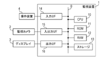
- FIG. 1 is a configuration example diagram of a monitoring system including a monitoring device according to the present embodiment.
- FIG. 1A is a hardware configuration diagram of the monitoring system
- FIG. 1B is a functional block diagram of the monitoring device.
- the monitoring system includes a monitoring device 1, one or more monitoring cameras (imaging devices) 2, a display (display device) 3, and an operation device 4.
- One or more monitoring cameras 2 are arranged at various locations in a monitoring area such as a building or a site, and each shoots an image within a shooting range.
- the display 3 displays an image based on the video imaged by each surveillance camera 2.
- the operation device 4 is a user interface of the monitoring device 1. In the first embodiment, a case where there is one surveillance camera 2 will be described, but the same processing is possible even when a plurality of surveillance cameras are provided.
- the monitoring device 1 acquires a video from the monitoring camera 2 and displays it on the display 3.
- the monitoring device 1 receives an instruction from the user through the operation device 4.
- Such a monitoring device 1 can be realized by a computer including a CPU (Central Processing Unit) 10, a ROM (Read Only Memory) 11, and a RAM (Random Access Memory) 12.
- the CPU 10 reads the computer program from the ROM 11 and executes it using the RAM 12 as a work area, thereby controlling the operation of the entire monitoring system.
- the CPU 10, ROM 11, and RAM 12 perform data transmission / reception via the bus B.
- a storage 13, an input interface (I / F) 14, an input / output interface (I / F) 15, and an output interface 16 (I / F) are connected to the bus B.
- the storage 13 is a large-capacity storage device, and records video acquired from the monitoring camera 2.
- the input I / F 14 receives an instruction or the like from the operation device 4 and inputs it to the CPU 10.
- the input / output I / F 15 is connected to the monitoring camera 2, controls the operation of the monitoring camera 2 under the control of the CPU 10, and obtains an image captured by the monitoring camera 2.
- the output I / F 16 is connected to the display 3 and displays an image on the display 3 under the control of the CPU 10.
- the monitoring device 1 includes functional blocks that function as the control unit 100, the imaging unit 101, the display unit 102, the display information management unit 103, the operation reception unit 104, the recording unit 105, the abnormality detection unit 106, and the attention time determination unit 107. . These functional blocks may be realized by the CPU 10 executing a computer program, but at least a part thereof may be configured by hardware.
- the control unit 100 controls the operation of each functional block.
- the imaging unit 101 controls the operation of the imaging device, imaging lens, drive motor, and the like of the monitoring camera 2 so that the monitoring camera 2 captures an image within the imaging range (monitoring area).
- the photographing unit 101 acquires a video photographed by the monitoring camera 2.
- the display unit 102 causes the display 3 to display an image based on the video acquired by the imaging unit 101 from the monitoring camera 2.
- the display information management unit 103 generates an image displayed on the display 3 by the display unit 102.
- the display information management unit 103 generates an image by superimposing layout and information on the video acquired by the imaging unit 101 from the monitoring camera 2.
- the operation accepting unit 104 accepts an instruction or the like from the monitor by the operation device 4.
- the operation device 4 is configured by a switch, a touch panel, and the like, and inputs an instruction or the like according to an operation by a monitoring person to the operation reception unit 104.
- the operation reception unit 104 sends the received instruction or the like to the control unit 100.
- the control unit 100 receives an instruction or the like from the operation reception unit 104, and performs processing according to the instruction or the like.
- the operation device 4 may include a pointing device such as a mouse or a trackball.
- the recording unit 105 sequentially records the video acquired by the imaging unit 101 from the monitoring camera 2 in the storage 13 together with metadata such as the imaging time and imaging conditions.
- the storage 13 of the present embodiment is a recording medium that is directly attached to the monitoring device 1 such as a hard disk or an SSD (Solid State Drive).
- the storage 13 can also be realized by a recording device on a network such as NAS (Network Attached Storage) or SAN (Storage Area Network).
- the anomaly detection unit 106 detects an anomaly of a human body or a moving body and an occurrence location thereof from the video acquired by the imaging unit 101 from the monitoring camera 2.
- the attention time determination unit 107 determines the attention time based on the time from the start time to the end time when the abnormality is detected based on the abnormality detection result by the abnormality detection unit 106.
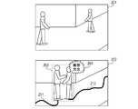
- FIG. 2 is an explanatory diagram of an image displayed on the display 3.
- Images 201 and 202 in FIG. 2A are images generated by the display information management unit 103 based on the video acquired by the imaging unit 101 from the monitoring camera 2.
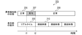
- FIG. 2B shows a timeline 205 when an abnormality is detected.
- the image 201 represents normal states 206 and 208, that is, a state where the abnormality detection unit 106 has not detected an abnormality.
- An image 201 is an image as it is acquired by the photographing unit 101 from the monitoring camera 2.
- the image 202 is an abnormal state 207, that is, a state where the abnormality detection unit 106 detects an abnormality.
- An image 202 is an image in which an abnormality occurrence point 203 and a warning display 204 are superimposed on the video acquired by the photographing unit 101 from the monitoring camera 2.
- the display information management unit 103 When the abnormality detection unit 106 detects the abnormal state 207, the display information management unit 103 generates an image 202 by superimposing the abnormality occurrence location 203 and the warning display 204 on the video acquired by the imaging unit 101 from the monitoring camera 2.
- the attention time determination unit 107 determines the attention time based on the start time and end time of the abnormality detected by the abnormality detection unit 106.
- the abnormality detection unit 106 always detects a person frame indicating the position of the person in the video.
- the display information management unit 103 superimposes the trajectories 211 and 212 on which the person has moved based on the person frame that is always detected.
- the timeline at the time of abnormality detection is as follows. Until time t1, the abnormality detection unit 106 has not detected an abnormality. Therefore, the display unit 102 displays the video acquired by the photographing unit 101 from the monitoring camera 2 on the display 3 in real time as it is. Hereinafter, an image acquired from the monitoring camera 2 and displayed in real time is referred to as a real time image 209.
- the attention time determination unit 107 starts measuring the attention time.
- the display unit 102 continues to display the real-time video 209. Since the real-time video 209 is displayed, the monitor can visually recognize the abnormal situation currently occurring on the display 3.
- the attention time determination unit 107 ends measuring the attention time.
- the attention time determination unit 107 acquires a recorded video 210 having a time corresponding to the attention time from the video recorded in the recording unit 105, and causes the display unit 102 to reproduce and display it on the display 3.
- the display unit 102 repeatedly displays and displays the recorded video 210 at the time of interest.
- the monitoring person can confirm the abnormal state from the recorded video 210 even when the real-time image 209 cannot confirm the abnormal state. Since the reproduction of the recorded video is after the abnormal end, the reproduction of the recorded video does not disturb the confirmation of the abnormality by the monitor when the abnormality is progressing in real time.
- FIG. 3 is a flowchart showing monitoring processing by the monitoring system. This process is always repeated during the operation of the monitoring system. This process ends when the monitoring system shuts down.
- the monitoring apparatus 1 uses the photographing unit 101 to constantly acquire video from the monitoring camera 2 while the monitoring system is operating.
- the control unit 100 records the video of the monitoring camera 2 acquired by the imaging unit 101 in the recording unit 105.
- the control unit 100 controls the display information management unit 103 and causes the display unit 102 to display the video acquired from the monitoring camera 2 on the display 3 in real time (S301). In a normal state in which no abnormality has occurred, the video taken by the surveillance camera 2 is displayed on the display 3 as it is.
- the control unit 100 controls the abnormality detection unit 106 to detect the occurrence of abnormality by analyzing the video during the display of the real-time video (S302).
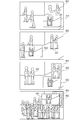
- FIG. 4 is an explanatory diagram of abnormality detection by the abnormality detection unit 106.
- the anomaly detection unit 106 constantly detects person frames 401 and 402 indicating the position of a person or moving object as a specific subject in the video, and detects an anomaly by determining the degree of abnormality of each person frame 401 and 402. .
- Table 410 illustrates information records associated with person frames 401 and 402.
- Person frames 401 and 402 are indicated by rectangles in the video.
- the abnormality detection unit 106 detects the width, height, and center coordinates in the video of the person frames 401 and 402 for each person.
- the abnormality detection unit 106 only needs to detect information that can uniquely represent the rectangles of the person frames 401 and 402 in the video.
- the coordinates of the upper left corner and the lower right corner may be used instead of the center coordinates, and the width and height may be detected.
- the coordinates of two diagonal points such as the upper left corner and the lower right corner may be used.
- the person frames 401 and 402 may be represented by polygons, ellipses, spline closed curves, or the like instead of rectangles.
- the person frames 401 and 402 are accompanied by rectangles 403 and 404 indicating the head position.
- the abnormality detection unit 106 detects the position of the head in the person frames 401 and 402 using the rectangles 403 and 404.
- the abnormality detection unit 106 derives the degree of abnormality for each person frame 401, 402 using a known method.
- the degree of abnormality is derived by the k-nearest neighbor method described in “V. Saligrama, et al. Video Anomaly Detection Based on Local Statistical Aggregates, CVPR 2012”.
- the abnormality detection unit 106 derives the degree of abnormality by a technique such as multiplying the neighborhood distance by an appropriate coefficient by the k-nearest neighbor method.
- the degree of abnormality is, for example, a numerical value indicating that the higher the value, the higher the probability of being abnormal.
- the abnormality detection unit 106 detects an abnormality when the degree of abnormality is higher than a predetermined threshold. Further, the abnormality detection unit 106 estimates the type of abnormality and determines the estimated abnormality type.
- the anomaly detection unit 106 detects the occurrence of an anomaly based on the information and positional relationship between the plurality of person frames 401 and 402 and the rectangles 403 and 404. In the example of FIG. 4, the abnormality detection unit 106 determines that an abnormality classified as assault in the frame 405 has occurred.
- a known method is used to determine the abnormality. For example, a DBN described in “Loy, S. Gong, et al. Detection and discriminating behavioral anomalies, Pattern Recognition 2011” is used. DBN is a dynamic Bayesian network.
- the abnormality detection unit 106 sequentially records the abnormality detection result in the recording unit 105 in association with the video.
- the control unit 100 controls the attention time determination unit 107 to determine the start time of the attention time based on the abnormality detection result of the abnormality detection unit 106 (S303). When it is determined that it is not the start time of the attention time (S303: N), the attention time determination unit 107 does not start measuring the attention time. In this case, the control unit 100 returns to the process of S301. When it is determined that it is the start time of the attention time (S303: Y), the attention time determination unit 107 starts measuring the attention time. Details of the determination process of the start time of the attention time will be described later.
- the control unit 100 controls the display information management unit 103 to generate an image at the time of abnormality detection, and causes the display unit 102 to display the generated image on the display 3 (S304). ).
- the display information management unit 103 generates an image at the time of abnormality detection by superimposing information representing the abnormality detected by the abnormality detection unit 106 on the real-time video acquired by the imaging unit 101 from the monitoring camera 2.
- the control unit 100 controls the abnormality detection unit 106 to determine the occurrence of abnormality by the same process as S302 (S305).
- the control unit 100 controls the attention time determination unit 107 to determine the end time of the attention time based on the abnormality detection result of the abnormality detection unit 106 by the process of S305 (S306). When it is determined that it is not the end time of the attention time (S306: N), the attention time determination unit 107 continues to measure the attention time. In this case, the control unit 100 returns to the process of S304 and causes the display 3 to display an image at the time of abnormality.
- the display information management unit 103 generates an image at the time of abnormality by superimposing information indicating the abnormality detected by the abnormality detection unit 106 in the processing of S302 and S305 on the real-time video acquired by the photographing unit 101 from the monitoring camera 2. To do.
- the attention time determination unit 107 ends the time measurement of the attention time.
- FIG. 5 is an explanatory diagram of processing in which the attention time determination unit 107 determines the start time and end time of the attention time. Note that the attention time determination unit 107 is not limited to the processing described below. For example, when the abnormality detection result indicates that an abnormality has occurred, the attention time determination unit 107 determines that the attention time is the start time, and the abnormality detection result indicates that the abnormality detection result is abnormal. When no occurrence is indicated, it may be determined that the end time of the attention time is reached.
- the attention time determination unit 107 sets the start time of the attention time to a time t1 'before the time t1.
- the time difference 501 between the time t1 and the time t1 ' is provided as a margin for the monitor to also check the situation before and after the abnormality.
- the photographing unit 101 acquires the video 512. That is, the abnormality detection unit 106 detects the occurrence of an abnormality from the video 512.
- the attention time determination unit 107 traces the person frame in the video 512 used for abnormality detection by the abnormality detection unit 106 retroactively, and the image 511 of the video 511 in which the person who has detected the abnormality starts to appear in the video of the monitoring camera 2.
- the shooting time is time t1 ′. That is, the attention time determination unit 107 includes the time from the time t1 'to the time t1 as the video related to the immediately following abnormality in the attention time, although the abnormality itself is not detected.
- a known moving body tracking method can be used as a known moving body tracking method.
- the attention time determination unit 107 continues the attention time while the abnormality detection unit 106 continues to detect abnormality from time t1. Note that when the abnormality detection is interrupted at intervals shorter than the predetermined threshold T as in the period 502, the attention time determination unit 107 ignores it and determines that the abnormality is detected.
- the control unit 100 starts the reproduction of the recorded video 210 at the attention time starting from the time t1 'by the display unit 102.
- the attention time determination unit 107 delays the determination of the end time t2 'of the attention time by a time difference 503 from the time t2. Due to the time difference 503, the situation advances from the video 513 to the video 514.
- the end time t2 'of the attention time is a point in time when the person frame for which the abnormality detection unit 106 is subject to abnormality detection disappears from the video, such as the video 513 to the video 514.
- the monitor can not only detect the period in which the abnormality is detected, but also the period in which the person involved in the abnormality is continuously present on the video captured by the monitoring camera 2. Including a series of abnormalities can be confirmed. Depending on the movement of the person frame, the time differences 501 and 503 may become too long. Therefore, the attention time determination unit 107 aborts the tracking of the person frame when it exceeds a predetermined length, for example, 10 seconds or a length of 1/5 of the duration of the abnormality from the time t1 to the time t2. The start time t1 ′ and the end time t2 ′ of the time may be determined.
- the control unit 100 controls the display information management unit 103 to reproduce and display the recorded video of the attention time in which an abnormality is detected on the display 3 by the display unit 102. (S307).
- the display information management unit 103 extracts and reproduces the video of the period corresponding to the attention time from the video sequentially recorded in the recording unit 105. Note that the display unit 102 performs loop playback of the recorded video of the same attention time after the playback is completed.
- the control unit 100 controls the abnormality detection unit 106 to determine the occurrence of abnormality by the same process as S302 (S308).
- the control unit 100 controls the attention time determination unit 107 to determine the start time of the attention time based on the abnormality detection result of the abnormality detection unit 106 by the process of S308 (S309).
- the attention time determination unit 107 determines whether or not an instruction to end the reproduction display of the recorded video is input from the operation device 4 by the operation receiving unit 104 (S310).
- the control unit 100 determines whether or not an instruction to end the reproduction display of the recorded video is input from the operation device 4 by the operation receiving unit 104 (S310).
- the end instruction has not been input (S310: N)
- the control unit 100 returns to the process of S307, and repeatedly reproduces and displays the recorded video at the time of interest.
- the end instruction is input (S310: Y)
- the control unit 100 returns to the process of S301 and starts displaying the real-time video.
- the monitor can instruct the end of reproduction by operating the button of the operation device 4, touch panel operation, voice input, gesture input, or line-of-sight input.
- an instruction to end reproduction may be input when the monitoring device 1 detects that the monitoring person has left the display 3 and the monitoring camera 2 has entered the imaging range of the monitoring camera 2.
- the attention time determination unit 107 determines that a new abnormality has occurred, and starts measuring the attention time.
- the attention time determination unit 107 updates the attention time based on the attention time used for the playback of the recorded video immediately before and the start time determined in the process of S309 (S311).
- the attention time determination unit 107 When the time difference between the start time of the new attention time and the end time of the immediately preceding attention time is less than a predetermined time (threshold T), for example, less than 10 seconds, the attention time determination unit 107 It is determined that it is integral with the attention time. That is, the attention time determination unit 107 sets the start time of the immediately preceding attention time as the new attention time start time. After updating the attention time, the control unit 100 returns to the process of S304.
- a predetermined time for example, less than 10 seconds
- the attention time determination unit 107 starts a new attention time when the time difference between the start time of the new attention time and the end time of the immediately preceding attention time is equal to or greater than a predetermined time (threshold T), for example, 10 seconds or more. It is determined that That is, the attention time determination unit 107 sets the start time determined in the process of S309 as the start time of a new attention time due to a new abnormality. After updating the attention time, the control unit 100 returns to the process of S304.
- a predetermined time for example, 10 seconds or more.
- Such processing of the attention time determination unit 107 is performed in order to provide a recorded video from the start of a series of abnormalities to the monitoring staff when abnormalities occur in a short time and treat them as a series of abnormalities. Is called.
- the monitoring system realizes the operation described with reference to FIG. 2, and can suppress the occurrence of an oversight of an abnormality without causing an obstacle to grasping the current state of the observer when an abnormality occurs. Therefore, when the abnormality occurs, the monitoring device 1 can cause the monitoring person to accurately determine the occurrence of the abnormality by correctly determining the attention time and repeatedly reproducing the recorded video.
- the monitoring system of the first embodiment replaces a recorded video at the time of interest with a real-time video and reproduces it. However, at the time of monitoring, the monitor may check the recorded video at the time of past abnormality detection by comparing the real-time video.
- the monitoring system according to the second embodiment displays the recorded video and the real-time video at the time of interest on the display 3 at the same time. Since the hardware configuration of the monitoring system of the second embodiment is the same as that of the first embodiment, description thereof is omitted.
- FIG. 6 is a functional block diagram of the monitoring device of the second embodiment.
- the monitoring device 5 has a function in which a layout determining unit 1108 is added to the functional block of the monitoring device 1 shown in FIG. 1B. The description of the same function is omitted.
- the layout determination unit 1108 determines how the display information management unit 103 arranges the recorded video of the time of interest in the image displayed on the display 3 and the real-time video.
- the display information management unit 103 generates an image that combines the recorded video and the real-time video according to the determination of the layout determination unit 1108, and displays the image on the display 3 by the display unit 102.
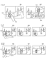
- FIG. 7 is an explanatory diagram of the arrangement of recorded video and real-time video.
- Images 601 to 604 are examples in which recorded video and real-time video are arranged in a layout determined by the layout determining unit 1108.
- the layout determining unit 1108 determines one of the real-time video and the recorded video as a background video and the other as a video to be displayed in a small window.
- the image 601 is an image at the timing of the end time of the attention time, and corresponds to the image at the time t2 in FIG.
- the image 601 is configured by superimposing a small window 611 obtained by reducing a recorded video at the time of interest on a real-time video.
- the monitor can check the current state of the site after the abnormal end by looking at the real-time video while checking the state of the abnormality that occurred just before looking at the small window 611 from the image 601.
- Such a display method is useful when simultaneously displaying a recorded video and a real-time video of the time of interest on a small screen such as a smartphone or a tablet terminal. Since a part of the real-time video is obscured by the small window 611, the display position of the small window 611 is controlled on the real-time video so as not to prevent confirmation of the abnormality that has occurred.
- the image 602 is an image when a new abnormality 621 occurs on the real-time video on which the recorded video of the time of interest is superimposed.
- the small window 622 for displaying the recorded video of the attention time is displayed by moving to a position avoiding the occurrence position of the abnormality 621 of the real-time video. Even if the small window 622 moves to a position that avoids the occurrence position of the abnormality 621 as shown in the image 602, due to the occurrence of a new abnormality, the movement position of the abnormality 621, the movement of the small window 622 by the operation of the monitor, etc.
- the occurrence position of the abnormality and the small window 622 may overlap.
- An image 603 is an image when another new abnormality 633 occurs after the small window 632 moves due to the occurrence of the abnormality 631.
- the small window 632 is superimposed on the real-time video, but a part of the small window 632 that is superimposed on the occurrence range of the abnormality 633 is missing.
- Image 604 is an image when abnormalities occur frequently. If a large number of abnormalities are detected in the entire video and it is inevitable to cover the abnormalities with the small windows, the small windows 641 are displayed so as to cover the abnormality occurrence positions 642 with as low anomaly as possible.
- the images 601 to 604 are examples in which the recorded video of the attention time of the small window is superimposed and displayed on the display screen of the same display 3 with the real-time video as the background, but the layout is not limited to this.
- the real-time video and the small window may be displayed separately on different display screens using a plurality of displays.
- a small window may be displayed in cooperation with a display screen of a mobile device such as a smartphone.
- FIG. 8 is a flowchart showing monitoring processing by the monitoring system of the second embodiment. The same steps as those in the monitoring process of the first embodiment shown in FIG. Description of the same processing is omitted.
- the control unit 100 determines that the attention time determination unit 107 determines that it is the end time of the attention time and ends the measurement of the attention time (S306: Y), or an instruction to end the reproduction of the recorded video from the operation device 4. If it is not input (S310: N), the layout of the image is determined. The layout of the image displayed on the display 3 is determined by the display information management unit 103 and the layout determination unit 1108. The control unit 100 causes the display unit 102 to simultaneously display the recorded video and the real-time video of the attention time on the display 3 according to the determined layout (S702). The processing after displaying the recorded video and the real-time video is the same as the processing after S308 in FIG.
- FIG. 9 is a flowchart showing the image layout determination processing in S701.
- the control unit 100 determines whether or not the operation receiving unit 104 has received an operation for determining a layout by the monitoring staff from the operation device 4 (S800).
- the monitor uses the touch panel of the operation device 4 to determine the position and size of the small window, and uses the toggle switch to display the recorded video of the attention time or the real-time video on the small window. You can choose.
- the control unit 100 maintains the previous layout in order to display the image in the layout desired by the monitor by the display information management unit 103 (S810).
- the control unit 100 proceeds to a process for automatically determining the layout. Note that, also when the layout determination process is performed for the first time after the time of interest is counted, the control unit 100 proceeds to a process of automatically determining the layout. Details of the layout determination operation by the monitoring staff will be described later.
- the control unit 100 causes the display information management unit 103 to determine the degree of abnormality at the current playback position of the recorded video at the time of interest and the degree of abnormality of the video captured by the monitoring camera 2 in real time. Are compared (S801).
- the display information management unit 103 calculates and compares the sum of the information of the abnormality detected by the abnormality detection unit 106 in each video.
- the layout determining unit 1108 displays the recorded video at the attention time on a small window and displays the real-time video on the background. (S802).
- the layout determining unit 1108 displays the recorded video at the attention time in the background and displays the real-time video in the small window. (S803).
- the video with the higher degree of abnormality is intended to be displayed on the front small window to make it easier to gaze, but the present invention is not limited to this, and the display of the small window may be determined by other methods.
- the recorded video of the attention time may be always displayed in a small window, or may be switched by the operation of the monitor.
- the layout determining unit 1108 determines the size of the small window (S804).
- the video displayed on the small window is reduced so that the short side of the small window on which the video with the highest degree of abnormality is displayed has a predetermined length, for example, 50 pixels.
- the size of the small window has an upper limit of half of the width and height of the background image and a lower limit of 1/4.
- the method of determining the size of the small window may be other methods, and is not limited to this.
- the display information management unit 103 derives a position where the small window can be displayed without covering the background image abnormality detection result by the abnormality detection unit 106 (S805).
- the display information management unit 103 for example, if the position of the previous small window does not cover the background image abnormality detection result, the display information management unit 103 determines the position from the background abnormality detection result when covering the background image abnormality detection result.
- the position at which the average distance is maximized is derived as the position where the small window can be displayed.
- the control unit 100 sends the background image abnormality detection result with the lowest degree of abnormality to the display information management unit 103. Exclude (S807). Thereafter, the display information management unit 103 derives again a position where the small window can be displayed (S805). The control unit 100 repeats the processing of S805 to S807, and acquires the position where the small window can be displayed while excluding the abnormality detection result of the background video in order from the lowest abnormality degree.
- the control unit 100 determines whether the display information management unit 103 immediately displays the position where the small window can be displayed. Select the position closest to the position of the small window. If there is only one displayable position, the display information management unit 103 selects it. In particular, the display information management unit 103 selects the position of the immediately preceding small window as it is if the position of the immediately preceding small window does not cover the abnormality detection result of the background image. As a result, it is possible to prevent the small window from moving greatly and becoming difficult to visually recognize.
- the control unit 100 uses the display information management unit 103 to remove the small window portion of the background abnormality detection result overlapping the small window so that the background abnormality detection area is not covered with the small window (S820). .
- the display information management unit 103 and the layout determination unit 1108 determine the display position of the small window so that the small window does not interfere with the background image.
- FIG. 10 is an explanatory diagram of the layout determination operation process using the operation device 4 by the monitor in S800.
- the monitor can determine, as a layout, the position of the small window, the size of the small window, and whether to display the recorded video or the real-time video of the attention time on the small window.
- the instructed layout is maintained by the supervisor instructing them.
- the position of the small window is that the monitor 901 drags the small window 911 on the touch panel of the operation device 4 with the finger 912 and moves it to the position of the small window 913 in the image 902 in a state where the image 901 is displayed on the display 3. Determined by At this time, if an abnormality that overlaps the position of the small window has been detected in the past, the display information management unit 103 displays a warning image 914 on the monitor.
- the size of the small window is determined by pinching in or out the small window on the touch panel of the operation device 4 by the monitor.
- the display information management unit 103 displays the small window 915 when the display of the small window 915 is a recorded video of the attention time. It is determined whether there is an abnormality detection result on the video.
- the display information management unit 103 performs trimming around the position where the abnormality detection result exists in the small window image as in the image 904.
- the display information management unit 103 displays the entire small window in a reduced manner as in the image 905.
- the display information management unit 103 displays the small window when the display of the small window 917 is a recorded video of the attention time. It is determined whether there is an abnormality detection result on the video 917. When there is an abnormality detection result, the display information management unit 103 enlarges and displays the entire small window like an image 907. When there is no abnormality detection result, the display information management unit 103 enlarges the trimming range centering on the abnormality detection result like an image 908. That is, the display information management unit 103 changes the operation of changing the size of the small windows 915 and 917 based on the detection result of the abnormality of the video displayed in the small windows 915 and 917.
- the image layout as described above is displayed with an emphasis on the anomaly detection results, presuming that the observer wants to particularly check the anomaly. To be done.
- Whether the recorded video of the attention time or the real-time video is displayed in the small window can be switched by, for example, operating the toggle switch of the operation device 4 by the supervisor.
- the toggle switch may be a physical switch or a virtual switch on the touch panel.
- the monitoring system can simultaneously display the recorded video and the real-time video of the attention time on the display 3 for the supervisor. Therefore, when an abnormality occurs, the monitoring system can suppress the occurrence of an oversight of the abnormality without causing any trouble in grasping the current state of the observer.
- the monitoring device 5 can cause the monitor to accurately determine the occurrence of the abnormality when the abnormality occurs.
- the monitoring system according to the third embodiment includes a plurality of monitoring cameras 2.
- the monitoring device 1 displays an image on the display 3 while switching videos acquired from a plurality of monitoring cameras 2.
- the overall configuration of the monitoring system is the same as the configuration shown in FIG. 1A except that there are a plurality of monitoring cameras 2.
- the plurality of monitoring cameras 2 are communicably connected to the monitoring device 1 via a network such as a LAN (Local Area Network).
- a network such as a LAN (Local Area Network).
- the imaging unit 101 of the monitoring device 1 acquires images from some or all of the plurality of monitoring cameras 2 at the same time.
- the abnormality detection unit 106 detects an abnormality for each of the videos acquired from the plurality of monitoring cameras 2.
- the attention time determination unit 107 determines the attention time by combining a plurality of video abnormality detection results acquired from the respective monitoring cameras 2.
- FIG. 11 is an explanatory diagram of processing in which the attention time determination unit 107 determines the start time and end time of the attention time.
- FIG. 11 illustrates a case where an abnormality has occurred in succession in the images taken by two surveillance cameras (camera A and camera B).
- the abnormality detection unit 106 determines normal 1001 and 1002 without detecting any abnormality in the images acquired from the camera A and the camera B.
- the attention time determination unit 107 determines the start of the attention time.
- the attention time determination unit 107 sets the time difference 501 as a margin as in FIG. 5 and determines the time t1 ′ as the start time of the attention time.
- the attention time determination unit 107 ends the attention time if the abnormality 1003 is longer than the threshold T, but the video of the camera B at a time interval shorter than the previous threshold T2 ( ⁇ T).
- the attention time is continued.
- the attention time determination unit 107 stores the time t3 when the abnormality 1004 occurs in the video of the camera B. Thereafter, the attention time determination unit 107 determines the end of the entire attention time by determining the interruption of the abnormality 1004.
- the attention time determination unit 107 determines the end of the attention time, and provides a time difference 503 as a margin as in FIG. t2 'is determined.
- the display unit 102 displays the video 1011 acquired from the camera A in real time on the display 3 until time t3, and displays the video 1012 acquired from the camera B in real time from time t3 to time t2.
- the display unit 102 reproduces and displays the recorded video 1013 of the attention time on the display 3.
- the recorded video 1013 of the attention time is a video acquired from the camera A at a time corresponding to the time from the time t1 'to the time t3, and a video acquired from the camera B at the time corresponding to the time from the time t3 to the time t2'.
- These recorded videos 1013 are taken out from the recording unit 105 and reproduced and displayed.
- the monitoring device 1 does not detect an abnormality in the images 1021 and 1031 acquired from the cameras A and B at the time t1 ′.
- the monitoring device 1 detects an abnormality 1003 from the video 1022 acquired from the camera A at time t.
- the abnormality of the image 1022 is “snacking”.
- the monitoring device 1 does not detect any abnormality from the video 1032 acquired from the camera B.
- the snatcher escapes to the right hand side in the video and disappears from the angle of view of the camera A.
- the abnormality detection unit 106 determines that the abnormality 1003 is interrupted at this time. However, a snatcher who escapes to the video 1033 acquired by the monitoring device 1 from the camera B at the time t3 appears.
- the abnormality detection unit 106 detects the abnormality 1004 from the video 1033 acquired from the camera B.
- the monitoring device 1 does not detect any abnormality in the images 1024 and 1034 acquired from the cameras A and B at the time t2 because the snatcher disappears from the angle of view of the camera B. Due to the abnormality that occurred in the series of flow from time t1 to time t2, the attention time determination unit 107 determines the time from time t1 'to time t2' as the attention time.
- the monitor can check a series of abnormalities without manually switching the images of the plurality of monitoring cameras (camera A and camera B).
- the above processing can be performed by processing based on the flowchart of FIG. 3 or FIG. By providing a plurality of surveillance cameras 2, the following processing is performed.
- the display information management unit 103 causes the display unit 102 to display images of the images of the plurality of monitoring cameras 2 on the display 3 in real time.
- the display unit 102 divides the display screen of the display 3, for example, to display a plurality of videos, or displays the videos while circulating at regular time intervals, according to an instruction from the display information management unit 103.
- the display unit 102 emphasizes and displays the video and the abnormality information in which the abnormality is detected according to the instruction of the display information management unit 103.
- the divided screens are integrated to display a video on which an abnormality has been detected on the display 3.
- the abnormality detection unit 106 performs abnormality detection on each video acquired from each monitoring camera 2, and outputs an abnormality detection result on each video.
- the attention time determination unit 107 determines the start time and end time of the attention time according to the processing described in FIG.
- the monitoring system reproduces the recorded video by using a series of abnormalities as the attention time when an abnormality occurs continuously in the plurality of monitoring cameras 2 so that the monitoring person can accurately confirm the abnormality. be able to. Therefore, when an abnormality occurs, the monitoring system can suppress the occurrence of an oversight of the abnormality without causing any trouble in grasping the current state of the observer.
- the monitoring device 1 can cause a monitoring person to accurately determine the occurrence of an abnormality when the abnormality occurs.
- the present invention supplies a program that realizes one or more functions of the above-described embodiments to a system or apparatus via a network or a storage medium, and one or more processors in a computer of the system or apparatus read and execute the program
- This process can be realized. It can also be realized by a circuit (for example, ASIC) that realizes one or more functions.
Landscapes
- Engineering & Computer Science (AREA)
- Multimedia (AREA)
- Physics & Mathematics (AREA)
- General Physics & Mathematics (AREA)
- Signal Processing (AREA)
- Theoretical Computer Science (AREA)
- Human Computer Interaction (AREA)
- Computer Vision & Pattern Recognition (AREA)
- Closed-Circuit Television Systems (AREA)
- Alarm Systems (AREA)
- Television Signal Processing For Recording (AREA)
- Burglar Alarm Systems (AREA)
Abstract
監視装置は、監視カメラ2から映像を取得してディスプレイ3に映像に基づく画像を表示する。監視装置1は、監視カメラ2から取得した映像を記録部105に記録する。監視装置1は、映像から異常を検知する異常検知部106と、検知した異常の開始から終了までの時間に基づく注目時間を判定する注目時間判定部107と、ディスプレイ3に、異常の検知を終了するまでは監視カメラ2から取得した映像をそのまま表示させ、異常の検知を終了すると注目時間に相当する時間の映像である録画映像を記録部105から取得して再生表示させる表示部102と、を備える。
Description
本発明は、監視カメラを用いた監視装置及びその方法に関する。
近年の遠隔監視システムには、監視カメラが撮影した映像に何らかの異常や変化等のイベントが発生したときに、監視員の見逃しを防止するために、自動的に映像の表示方法を切り替える機能を備えるものがある。特開2012-14543号公報は、複数台の監視カメラの映像を巡回表示する監視装置を開示する。この監視装置は、あるカメラの映像から異常が検知されると、そのカメラの映像の次回の巡回表示の際に異常の発生を含む期間の録画映像を再生する。特開2008-54243号公報は、複数台の監視カメラのいずれかの映像から異常を検知すると、全ての監視カメラの映像を、異常を検知した監視カメラの映像に切り替え、異常の検知が終了すると、異常を検知した監視カメラの映像の表示を終了する監視装置を開示する。
特開2012-14543号公報の監視装置は、巡回表示の切り替え周期よりも長く異常が継続した場合に、リアルタイムで異常が継続しているにもかかわらず録画映像に切り替わってしまい、監視員の正しい現状把握に支障をきたす可能性がある。特開2008-54243号公報の監視装置は、映像上ではごく短時間で終了する異常の場合はすぐに表示が正常に戻ってしまい、監視員が異常の発生を見落とす可能性がある。
本発明は、上記課題に鑑みてなされたものであり、監視員が異常を正確に判断できる監視装置を提供することを主たる目的とする。
本発明の監視装置は、撮影装置により撮影された映像を取得する取得手段と、前記映像に基づく画像を表示装置に表示する表示手段と、前記映像を記録する記録手段と、前記映像から異常を検知する検知手段と、前記検知手段が検知した前記異常の開始から終了までの時間に基づく注目時間を判定する判定手段と、前記表示手段に、前記異常の検知を終了するまでは前記撮影手段が取得した前記映像をそのまま表示させ、前記異常の検知を終了すると前記注目時間に対応する録画映像を前記記録手段から取得して再生表示させる制御手段と、を備える。
本発明によれば、異常の開始から終了まで注目時間の映像を異常の検知を終了した後に表示することで、監視員が異常をより正確に把握することができるようになる。
以下、図面を参照して実施の形態を詳細に説明する。
(第1実施形態)
図1は、本実施形態の監視装置を含む監視システムの構成例示図である。図1Aは、監視システムのハードウェア構成図、図1Bは、監視装置の機能ブロック図である。監視システムは、監視装置1、1台以上の監視カメラ(撮像装置)2、ディスプレイ(表示装置)3、及び操作装置4を備える。1台以上の監視カメラ2は、例えば建物や敷地内等の監視エリア内の各所に配置され、それぞれが、撮影範囲内の映像を撮影する。ディスプレイ3は、各監視カメラ2により撮影された映像に基づく画像を表示する。操作装置4は、監視装置1のユーザインタフェースである。第1実施形態では監視カメラ2が1台の場合を説明するが、複数台設けられる場合であっても同様の処理が可能である。
図1は、本実施形態の監視装置を含む監視システムの構成例示図である。図1Aは、監視システムのハードウェア構成図、図1Bは、監視装置の機能ブロック図である。監視システムは、監視装置1、1台以上の監視カメラ(撮像装置)2、ディスプレイ(表示装置)3、及び操作装置4を備える。1台以上の監視カメラ2は、例えば建物や敷地内等の監視エリア内の各所に配置され、それぞれが、撮影範囲内の映像を撮影する。ディスプレイ3は、各監視カメラ2により撮影された映像に基づく画像を表示する。操作装置4は、監視装置1のユーザインタフェースである。第1実施形態では監視カメラ2が1台の場合を説明するが、複数台設けられる場合であっても同様の処理が可能である。
監視装置1は、監視カメラ2から映像を取得してディスプレイ3に表示する。監視装置1は、操作装置4によりユーザからの指示を受け付ける。このような監視装置1は、CPU(Central Processing Unit)10、ROM(Read Only Memory)11、及びRAM(Random Access Memory)12を備えるコンピュータで実現できる。CPU10は、ROM11からコンピュータプログラムを読み込み、RAM12を作業領域に用いて実行することで、監視システム全体の動作を制御する。CPU10、ROM11、及びRAM12は、バスBを介してデータの送受信を行う。バスBには、ストレージ13、入力インタフェース(I/F)14、入出力インタフェース(I/F)15、及び出力インタフェース16(I/F)が接続される。ストレージ13は、大容量記憶装置であり、監視カメラ2から取得した映像を記録する。入力I/F14は操作装置4から指示等を受け付けてCPU10に入力する。入出力I/F15は、監視カメラ2に接続されており、CPU10の制御により監視カメラ2の動作を制御し且つ監視カメラ2が撮影した映像を取得する。出力I/F16は、ディスプレイ3に接続されており、CPU10の制御によりディスプレイ3に画像を表示させる。
監視装置1は、制御部100、撮影部101、表示部102、表示情報管理部103、操作受付部104、記録部105、異常検知部106、及び注目時間判定部107として機能する機能ブロックを有する。これらの機能ブロックは、CPU10がコンピュータプログラムを実行することで実現されてもよいが、少なくとも一部がハードウェアにより構成されていてもよい。
制御部100は、各機能ブロックの動作を制御する。撮影部101は、監視カメラ2の撮像素子、撮像レンズ、駆動モータ等の動作を制御し、監視カメラ2に撮影範囲内(監視領域)を撮影させる。撮影部101は、監視カメラ2で撮影された映像を取得する。表示部102は、ディスプレイ3に、撮影部101が監視カメラ2から取得した映像に基づく画像を表示させる。表示情報管理部103は、表示部102によりディスプレイ3に表示される画像を生成する。表示情報管理部103は、撮影部101が監視カメラ2から取得した映像にレイアウトや情報の重畳を行って画像を生成する。
操作受付部104は、操作装置4による監視員からの指示等を受け付ける。操作装置4は、スイッチやタッチパネル等によって構成され、監視員による操作に応じた指示等を操作受付部104に入力する。操作受付部104は、受け付けた指示等を制御部100に送る。制御部100は、操作受付部104から指示等を受信し、指示等に応じた処理を行う。なお、操作装置4は、マウスやトラックボール等のポインティングデバイスを備えていてもよい。
記録部105は、撮影部101が監視カメラ2から取得した映像を、撮影時刻、撮影条件等のメタデータとともに、逐次、ストレージ13に記録する。本実施形態のストレージ13は、例えばハードディスクやSSD(Solid State Drive)のように監視装置1に直接取り付けられる記録メディアである。また、ストレージ13は、NAS(Network Attached Storage)やSAN(Storage Area Network)等のネットワーク上の記録装置により実現することも可能である。
異常検知部106は、撮影部101が監視カメラ2から取得した映像から人体又は動体の異常及びその発生個所を検知する。注目時間判定部107は、異常検知部106による異常の検知結果により、異常を検知した開始時刻から終了時刻までの時間に基づく注目時間を判定する。
図2は、ディスプレイ3に表示される画像の説明図である。図2Aの画像201、202は、撮影部101が監視カメラ2から取得した映像に基づいて表示情報管理部103が生成する画像である。図2Bは、異常検知時のタイムライン205を表す。
画像201は、正常状態206、208、すなわち異常検知部106が異常を検知していない状態を表す。画像201は、撮影部101が監視カメラ2から取得した映像そのままの画像である。
画像202は、異常状態207、すなわち異常検知部106が異常を検知している状態である。画像202は、撮影部101が監視カメラ2から取得した映像に異常の発生箇所203及び警告表示204が重畳された画像である。表示情報管理部103は、異常検知部106が異常状態207を検知すると、異常の発生箇所203及び警告表示204を撮影部101が監視カメラ2から取得した映像に重畳して画像202を生成する。注目時間判定部107は、異常検知部106が検知する異常の開始時刻及び終了時刻に基づいて注目時間を判定する。
なお、異常検知部106は、映像中の人物の位置を示す人物枠を常時検出している。表示情報管理部103は、異常検知部106が異常状態を検知すると、常時検出される人物枠に基づいて、該人物が移動した軌跡211、212を映像に重畳する。
異常検知時のタイムラインは、以下のようになる。時刻t1までは、異常検知部106は異常を検知していない。そのために表示部102は、ディスプレイ3に、撮影部101が監視カメラ2から取得した映像を、そのままリアルタイム表示する。以下、監視カメラ2から取得してリアルタイム表示する映像をリアルタイム映像209という。
異常検知部106が時刻t1で異常を検知すると、注目時間判定部107は、注目時間の計時を開始する。表示部102は、リアルタイム映像209の表示を継続する。リアルタイム映像209が表示されるために、監視員は、現在発生している異常の状況をディスプレイ3により視認することができる。
時刻t2で異常検知部106が異常の検知を終了すると、注目時間判定部107は注目時間の計時を終了する。注目時間判定部107は、記録部105に記録された映像から注目時間に相当する時間の録画映像210を取得して、表示部102によりディスプレイ3に再生表示させる。時刻t2以降、表示部102は、注目時間の録画映像210の再生表示を繰り返し行う。これにより監視員は、リアルタイム映像209で異常の状況を確認できない場合であっても、録画映像210によって異常の状況を確認することができる。録画映像の再生が異常終了後であるため、録画映像の再生により、リアルタイムで異常が進行しているときの監視員による異常の確認を妨害することがない。
図3は、監視システムによる監視処理を表すフローチャートである。この処理は、監視システムの稼働中に、常時、繰り返し行われる。監視システムのシャットダウンにより、この処理は終了する。監視装置1は、撮影部101により、監視システムの稼働中に監視カメラ2から常時映像を取得する。制御部100は、撮影部101により取得した監視カメラ2の映像を記録部105に記録する。
監視システムの稼働中、制御部100は、表示情報管理部103を制御し、撮影部101が監視カメラ2から取得した映像を、表示部102によりディスプレイ3にリアルタイム表示させる(S301)。異常が発生していない正常状態では、監視カメラ2が撮影した映像が、ディスプレイ3にそのまま表示される。制御部100は、異常検知部106を制御し、リアルタイム映像の表示中に、該映像を解析して異常の発生を検知する(S302)。
図4は、異常検知部106による異常検知の説明図である。異常検知部106は、映像中の特定の被写体として人物又は動体の位置を示す人物枠401、402を常時検出しており、各人物枠401、402の異常度を判定して、異常を検知する。表410は、人物枠401、402に付随する情報レコードを例示する。
人物枠401、402は映像中に矩形で示される。異常検知部106は、人物枠401、402の映像中における幅、高さ、及び中心座標を、人物毎に検出する。なお、異常検知部106は、人物枠401、402の矩形を映像中で一意に表現できる情報を検出すればよく、例えば中心座標の代わりに左上隅や右下隅の座標でもよく、幅、高さの代わりに左上隅と右下隅等の対角の二点の座標でもよい。また、人物枠401、402は、矩形の代わりに多角形、楕円、スプライン閉曲線等で表されてもよい。人物枠401、402には、頭部位置を示す矩形403、404が付随する。異常検知部106は、矩形403、404により人物枠401、402の中の頭部位置を検出する。
異常検知部106は、人物枠401、402毎に、公知の手法を用いて異常度を導出する。例えば、「V. Saligrama, et al. Video Anomaly Detection Based on Local Statistical Aggregates, CVPR 2012」記載のk近傍法により、異常度が導出される。異常検知部106は、k近傍法により、近傍距離に適当な係数を乗算する等の手法で異常度を導出する。異常度は、例えば、値が大きいほど異常である蓋然性が高いことを表す数値である。異常検知部106は、異常度が所定の閾値よりも高い場合に異常を検知する。また、異常検知部106は、異常の種類を推定して、推定異常種を決定する。
異常検知部106は、複数の人物枠401、402、矩形403、404の情報及び位置関係に基づいて、異常の発生を検知する。図4の例では、異常検知部106は、枠405において暴行に分類される異常が発生していると判定する。異常の判定には公知の手法が用いられる。例えば、「Loy, S. Gong, et al. Detecting and discriminating behavioral anomalies, Pattern Recognition 2011」記載のDBNが用いられる。DBNは、動的ベイジアンネットワークである。異常検知部106は、異常検知結果を映像に紐づけて記録部105に逐次記録する。
制御部100は、注目時間判定部107を制御して、異常検知部106の異常検知結果に基づいて、注目時間の開始時刻を判定する(S303)。注目時間の開始時刻ではないと判定した場合(S303:N)、注目時間判定部107は注目時間の計時を開始しない。この場合、制御部100は、S301の処理に戻る。注目時間の開始時刻であると判定した場合(S303:Y)、注目時間判定部107は、注目時間の計時を開始する。注目時間の開始時刻の判定処理の詳細は後述する。
注目時間の計時が開始されると、制御部100は、表示情報管理部103を制御して、異常検知時の画像を生成し、生成された画像を表示部102によりディスプレイ3に表示させる(S304)。表示情報管理部103は、撮影部101が監視カメラ2から取得したリアルタイム映像に、異常検知部106が検知した異常を表す情報を重畳することで異常検知時の画像を生成する。制御部100は、異常検知時の画像を表示後に、異常検知部106を制御して、S302と同様の処理による異常の発生の判定を行う(S305)。
制御部100は、注目時間判定部107を制御して、S305の処理による異常検知部106の異常検知結果に基づいて、注目時間の終了時刻を判定する(S306)。注目時間の終了時刻ではないと判定した場合(S306:N)、注目時間判定部107は注目時間の計時を継続する。この場合、制御部100は、S304の処理に戻り、異常時の画像をディスプレイ3に表示させる。表示情報管理部103は、撮影部101が監視カメラ2から取得したリアルタイムの映像に、異常検知部106がS302及びS305の処理で検知した異常を表す情報を重畳することで異常時の画像を生成する。
一方、注目時間の終了時刻であると判定した場合(S306:Y)、注目時間判定部107は、注目時間の計時を終了する。
図5は、注目時間判定部107が注目時間の開始時刻及び終了時刻を判定する処理の説明図である。なお、注目時間判定部107は、以下に説明する処理に限らず、例えば単に異常検知結果が異常の発生を示しているときに注目時間の開始時刻であると判定し、異常検知結果が異常の発生を示さないときに注目時間の終了時刻であると判定してもよい。
異常検知部106が時刻t1に異常を検知する場合、注目時間判定部107は、注目時間の開始時刻を、時刻t1より以前の時刻t1’に設定する。時刻t1と時刻t1’との時間差501は、監視員が異常の前後の状況もあわせて確認するためのマージンとして設けられる。異常発生時、すなわち時刻t1の時点で撮影部101は映像512を取得している。つまり異常検知部106は、映像512により異常の発生を検知する。注目時間判定部107は、異常検知部106が異常検知に用いた映像512中の人物枠を遡って追跡し、異常検知の対象となった人物が監視カメラ2の映像に映り始めた映像511の撮影時刻を時刻t1’とする。すなわち、注目時間判定部107は、時刻t1’から時刻t1までを、異常自体は検知されていないものの、直後の異常に関連する映像として注目時間に含める。人物枠の追跡の方法は、公知の動体追尾方法を用いることができる。
注目時間判定部107は、時刻t1から異常検知部106が異常を検知し続ける間、注目時間を継続する。なお、注目時間判定部107は、期間502のように所定の閾値Tよりも短い間隔で異常の検知が途切れた場合、それを無視して異常が検知されていると判定する。
閾値Tよりも長い時間の異常の途切れが発生した時刻t2に到達すると、制御部100は、表示部102により時刻t1’から始まる注目時間の録画映像210の再生を開始する。しかし注目時間判定部107は、注目時間の終了時刻t2’の決定を時刻t2から時間差503だけ遅らせる。時間差503により、映像513から映像514に状況が進む。注目時間の終了時刻t2’は、映像513から映像514のように、異常検知部106が異常検知の対象となった人物枠が映像から消失した時点である。
このように注目時間が判定されることで、監視員は、単に異常が検知された期間のみならず、異常に関わった人物が監視カメラ2により撮影される映像上に継続して存在する期間を含めて、一連の異常を確認することができる。なお、人物枠の移動によっては、時間差501、503が長くなりすぎることがある。そのために注目時間判定部107は、所定の長さ、例えば10秒や、時刻t1から時刻t2までの異常の継続期間の5分の1等の長さを超えると人物枠の追跡を打ち切り、注目時間の開始時刻t1’や終了時刻t2’を決定してもよい。
以上のような処理により注目時間が判定されると、制御部100は、表示情報管理部103を制御して、異常が検知されている注目時間の録画映像を表示部102によりディスプレイ3に再生表示させる(S307)。表示情報管理部103は、記録部105に逐次記録されている映像から注目時間に対応する期間の映像を取り出して再生させる。なお、表示部102は、再生が完了した後に同じ注目時間の録画映像をループ再生する。
制御部100は、異常検知部106を制御して、S302と同様の処理により異常の発生の判定を行う(S308)。制御部100は、注目時間判定部107を制御して、S308の処理による異常検知部106の異常検知結果に基づいて、注目時間の開始時刻を判定する(S309)。
注目時間の開始時刻ではないと判定した場合(S309:N)、つまり新たな異常が発生していない場合、注目時間判定部107は、注目時間を計時しない。制御部100は、注目時間を計時しない場合に、操作受付部104により操作装置4から録画映像の再生表示を終了する指示が入力されたか否かを判定する(S310)。終了の指示が入力されていない場合(S310:N)、制御部100は、S307の処理に戻り、注目時間の録画映像の再生表示を繰り返して行う。終了の指示が入力された場合(S310:Y)、制御部100は、S301の処理に戻り、リアルタイム映像の表示を開始する。監視員は、操作装置4のボタン操作やタッチパネル操作、音声入力、ジェスチャ入力、視線入力により再生の終了を指示することができる。また、監視員のディスプレイ3の前からの離脱、監視カメラ2の撮影範囲内への監視員の侵入を監視装置1が検知することで、再生の終了の指示が入力されてもよい。
注目時間の開始時刻であると判定した場合(S309:Y)、注目時間判定部107は新たな異常が発生したと判定して、注目時間の計時を開始する。注目時間判定部107は、直前に録画映像の再生に用いた注目時間と、S309の処理で判定した開始時刻とに基づいて、注目時間を更新する(S311)。
注目時間判定部107は、新たな注目時間の開始時刻と、直前の注目時間の終了時刻との時間差が所定の時間(閾値T)未満、例えば10秒未満である場合、新たな注目時間が直前の注目時間と一体であると判定する。すなわち注目時間判定部107は、直前の注目時間の開始時刻を新たな注目時間の開始時刻とする。注目時間の更新後、制御部100はS304の処理に戻る。
注目時間判定部107は、新たな注目時間の開始時刻と、直前の注目時間の終了時刻との時間差が所定の時間(閾値T)以上、例えば10秒以上である場合、新たな注目時間が始まったと判定する。すなわち注目時間判定部107は、S309の処理で判定した開始時刻を新たな異常による新たな注目時間の開始時刻とする。注目時間の更新後、制御部100はS304の処理に戻る。
注目時間判定部107のこのような処理は、短時間で続けて異常が発生した場合に、これを一連の異常として取り扱い、一連の異常の開始からの録画映像を監視員に提供するために行われる。
以上のように監視システムは、図2で説明した動作を実現し、異常が発生したときに、監視員の現状把握に支障をきたすことなく、且つ異常の見落としの発生を抑制することができる。そのために監視装置1は、異常発生時に、注目時間を正しく判定して録画映像を繰り返し再生することで、監視員に異常の発生を正確に判断させることができる。
(第2実施形態)
第1実施形態の監視システムは、注目時間の録画映像をリアルタイム映像に入れ替えて再生する。しかし監視員は、監視時に、過去の異常検知時の録画映像と、リアルタイム映像とを見比べて確認することもある。第2実施形態の監視システムは、注目時間の録画映像とリアルタイム映像とを同時にディスプレイ3に表示する。第2実施形態の監視システムのハードウェア構成は第1実施形態と同様であるために、説明を省略する。
第1実施形態の監視システムは、注目時間の録画映像をリアルタイム映像に入れ替えて再生する。しかし監視員は、監視時に、過去の異常検知時の録画映像と、リアルタイム映像とを見比べて確認することもある。第2実施形態の監視システムは、注目時間の録画映像とリアルタイム映像とを同時にディスプレイ3に表示する。第2実施形態の監視システムのハードウェア構成は第1実施形態と同様であるために、説明を省略する。
図6は、第2実施形態の監視装置の機能ブロック図である。監視装置5は、図1Bに示す監視装置1の機能ブロックにレイアウト決定部1108を追加した機能を備える。同じ機能については説明を省略する。レイアウト決定部1108は、表示情報管理部103がディスプレイ3に表示される画像内の注目時間の録画映像と、リアルタイム映像とをどのように配置するかを決定する。表示情報管理部103は、レイアウト決定部1108の決定に従って録画映像とリアルタイム映像とを組み合わせた画像を生成し、表示部102によりディスプレイ3に表示する。
図7は、録画映像とリアルタイム映像との配置の説明図である。画像601~604は、録画映像とリアルタイム映像とが、レイアウト決定部1108の決定したレイアウトで配置される例である。レイアウト決定部1108は、リアルタイム映像及び録画映像の一方を背景映像に決定し、他方を小窓に表示する映像に決定する。
画像601は、注目時間の終了時刻のタイミングにおける画像であり、図2の時刻t2の時点の画像に当たる。画像601は、リアルタイム映像上に、注目時間の録画映像を縮小した小窓611が重畳されて構成される。監視員は、画像601により、小窓611を見て直前に発生した異常の状況を確認しつつ、リアルタイム映像を見て異常終了後の現地の現況を確認することができる。このような表示方法は、スマートフォンやタブレット端末等の小さな画面で、注目時間の録画映像とリアルタイム映像とを同時に表示する際に役立つ。リアルタイム映像の一部分が小窓611により覆い隠されるために、発生した異常の確認の妨げにならないように、小窓611の表示位置がリアルタイム映像上で制御される。
画像602は、注目時間の録画映像が重畳されたリアルタイム映像上で新たな異常621が発生した場合の画像である。注目時間の録画映像を表示する小窓622は、リアルタイム映像の異常621の発生位置を避けた位置に移動して表示される。画像602のように小窓622が異常621の発生位置を避けた位置に移動しても、新たな異常の発生、異常621の発生位置の移動、監視員の操作による小窓622の移動等により、異常の発生位置と小窓622とが重なる場合がある。画像603は、異常631の発生により小窓632が移動した後で、別の新たな異常633が発生した場合の画像である。小窓632は、リアルタイム映像に重畳されるが、異常633の発生範囲に重畳する一部分が欠けている。
画像604は、異常が多発した場合の画像である。異常が映像全体で多数検知され、小窓で異常を覆い隠すことが不可避であれば、なるべく異常度の低い異常の発生位置642を覆うようにして、小窓641が表示される。
画像601~604は、同一のディスプレイ3の表示画面内に、リアルタイム映像を背景として、小窓の注目時間の録画映像を重畳して表示する例であるが、レイアウトはこれに限られない。複数のディスプレイを用いて、リアルタイム映像と小窓とが異なる表示画面に分けて表示されてもよい。例えば、スマートフォン等のモバイルデバイスの表示画面と連携して、小窓が表示されてもよい。
図8は、第2実施形態の監視システムによる監視処理を表すフローチャートである。図3に示す第1実施形態の監視処理と同じ処理には同じステップ番号が付してある。同じ処理については説明を省略する。
制御部100は、注目時間判定部107が注目時間の終了時刻であると判定して注目時間の計時を終了する場合(S306:Y)、或いは操作装置4から録画映像の再生を終了する指示が入力されていない場合(S310:N)に、画像のレイアウトを決定する。ディスプレイ3に表示する画像のレイアウトは、表示情報管理部103及びレイアウト決定部1108により決定される。制御部100は、表示部102により、決定したレイアウトに応じて、注目時間の録画映像とリアルタイム映像とを同時にディスプレイ3に表示する(S702)。録画映像とリアルタイム映像とを表示した後の処理は、図3のS308以降の処理と同様である。
図9は、S701の画像のレイアウト決定処理を表すフローチャートである。
制御部100は、操作受付部104が操作装置4から監視員によるレイアウトを決定する操作を受け付けているか否かを判定する(S800)。監視員は、操作装置4のタッチパネルを用いて、小窓の位置や大きさを決定したり、トグルスイッチを用いて、小窓に注目時間の録画映像とリアルタイム映像とのどちらを表示するかを選択することができる。レイアウトを決定する操作を受け付けた場合(S800:Y)、制御部100は、表示情報管理部103により、監視員の希望するレイアウトで画像を表示するために、直前のレイアウトを維持する(S810)。レイアウトを決定する操作を受け付けていない場合(S800:N)、制御部100は、レイアウトを自動的に決定する処理に移行する。なお、注目時間の計時が終了して最初にレイアウト決定処理を行う場合にも、制御部100は、レイアウトを自動的に決定する処理に移行する。監視員によるレイアウト決定の操作についての詳細は後述する。
レイアウトを自動的に決定する場合、制御部100は、表示情報管理部103により、注目時間の録画映像の現在の再生位置における異常度と、監視カメラ2がリアルタイムで撮影している映像の異常度とを比較する(S801)。表示情報管理部103は、それぞれの映像で異常検知部106が検知した異常の情報の合計を算出して比較する。注目時間の録画映像の異常度がリアルタイム映像の異常度よりも高い場合(S801:Y)、レイアウト決定部1108は、注目時間の録画映像を小窓に表示し、リアルタイム映像を背景に表示するように決定する(S802)。リアルタイム映像の異常度が注目時間の録画映像の異常度よりも高い場合(S801:N)、レイアウト決定部1108は、注目時間の録画映像を背景に表示し、リアルタイム映像を小窓に表示するように決定する(S803)。ここでは、異常度の高い方の映像を前面の小窓に表示して、より注視しやすくすることを意図しているが、これに限らず他の方法で小窓の表示を定めてもよい。例えば注目時間の録画映像を常に小窓に表示するようにしたり、監視員の操作で切り替えるようにしてもよい。
レイアウト決定部1108は、小窓の大きさを決定する(S804)。ここでは、最も異常度の高い映像が表示される小窓の短辺が所定の長さ、例えば50ピクセルになるように、小窓に表示される映像の縮小を行う。ただし、小窓の大きさは、背景の映像の幅及び高さの半分を上限、4分の1を下限とする。なお、小窓の大きさの決め方は他の方法でもよく、これに限るものではない。
表示情報管理部103は、異常検知部106による背景の映像の異常検知結果を覆い隠さずに小窓を表示可能な位置を導出する(S805)。表示情報管理部103は、例えば、直前の小窓の位置が、背景の映像の異常検知結果を覆い隠さない場合にはその位置を、覆い隠す場合にはすべての背景の映像の異常検知結果からの平均距離が最大になる位置を、小窓を表示可能な位置として導出する。
制御部100は、表示情報管理部103が小窓を表示可能な位置を一つも導出できない場合に(S806:N)、表示情報管理部103に、最も異常度の低い背景映像の異常検知結果を除外させる(S807)。その後、表示情報管理部103は、小窓を表示可能な位置を再度導出する(S805)。制御部100は、S805~S807の処理を繰り返し続けることで、背景の映像の異常検知結果を異常度の低い方から順に除外しながら、小窓が表示可能な位置を取得する。
制御部100は、表示情報管理部103が小窓を表示可能な位置を導出した場合に(S806:Y)、表示情報管理部103により、導出した小窓の表示可能な位置のうち、直前の小窓の位置に最も近い位置を選択する。表示情報管理部103は、表示可能な位置が一つしかなければそれを選択する。特に、表示情報管理部103は、直前の小窓の位置が背景の映像の異常検知結果を覆い隠さないのであれば直前の小窓の位置をそのまま選択する。これにより、小窓が大きく移動して視認しづらくなることを防止することができる。制御部100は、表示情報管理部103により、小窓と重なる背景の映像の異常検知結果の小窓部分を除去して、背景の異常検知領域が小窓で覆い隠されないようにする(S820)。
以上のように表示情報管理部103及びレイアウト決定部1108は、小窓が背景の映像の妨げにならないように、小窓の表示位置を決定する。
図10は、S800の監視員による操作装置4を用いたレイアウト決定の操作処理の説明図である。監視員は、レイアウトとして、小窓の位置、小窓の大きさ、注目時間の録画映像とリアルタイム映像とのどちらを小窓に表示するか、について決定することができる。これらを監視員が指示することで、指示したレイアウトが維持される。
小窓の位置は、ディスプレイ3に画像901が表示される状態で、監視員が操作装置4のタッチパネル上の小窓911を指912によりドラッグし、画像902の小窓913の位置に移動させることで決定される。この際に表示情報管理部103は、小窓の位置に重なるような異常が過去に検知されていれば、監視員に警告画像914を表示させる。
小窓の大きさは、監視員が操作装置4のタッチパネル上の小窓をピンチイン又はピンチアウトすることで決定される。ディスプレイ3に画像903が表示される状態で監視員が小窓915をピンチイン916すると、表示情報管理部103は、小窓915の表示が注目時間の録画映像である場合には、小窓915の映像上に異常検知の結果があるかどうかを判定する。異常検知の結果がある場合、表示情報管理部103は、画像904のように、小窓の映像のうち異常検知の結果がある位置を中心にしてトリミングを行う。異常検知の結果がない場合、表示情報管理部103は、画像905のように小窓の全体を縮小表示する。
ディスプレイ3に画像906が表示されている状態で監視員が小窓917をピンチアウト918すると、表示情報管理部103は、小窓917の表示が注目時間の録画映像である場合には、小窓917の映像上に異常検知の結果があるかどうかを判定する。異常検知の結果がある場合、表示情報管理部103は、画像907のように小窓の全体を拡大表示する。異常検知の結果がない場合、表示情報管理部103は、画像908のように異常検知の結果を中心にトリミングの範囲を拡大する。つまり表示情報管理部103は、小窓915、917の大きさを変更する操作を、小窓915、917に表示される映像の異常の検知結果に基づいて変更する。
以上のような画像のレイアウトは、例えば異常検知の結果がある録画映像が小窓に表示される場合、異常部分を監視員が特に確認したいと推定して、異常検知の結果を強調して表示するために行われる。注目時間の録画映像とリアルタイム映像とのどちらを小窓に表示するかは、例えば監視員が操作装置4のトグルスイッチを操作することで切り替え可能である。トグルスイッチは、物理的なスイッチでもよいし、タッチパネル上の仮想的なスイッチでもよい。
以上のように監視システムは、監視員に対して注目時間の録画映像とリアルタイム映像とを同時にディスプレイ3に表示することができる。そのために監視システムは、異常が発生したときに、監視員の現状把握に支障をきたすことなく、且つ異常の見落としの発生を抑制することができる。監視装置5は、異常発生時に、監視員に異常の発生を正確に判断させることができる。
(第3実施形態)
第3実施形態の監視システムは、複数台の監視カメラ2を備える。監視装置1は、複数台の監視カメラ2から取得する映像を切り替えながら、ディスプレイ3に画像を表示する。監視システムの全体構成は、監視カメラ2が複数台になったことを除いて、図1Aに示す構成と同じである。複数台の監視カメラ2は、LAN(Local Area Network)等のネットワークを介して監視装置1に通信可能に接続される。
第3実施形態の監視システムは、複数台の監視カメラ2を備える。監視装置1は、複数台の監視カメラ2から取得する映像を切り替えながら、ディスプレイ3に画像を表示する。監視システムの全体構成は、監視カメラ2が複数台になったことを除いて、図1Aに示す構成と同じである。複数台の監視カメラ2は、LAN(Local Area Network)等のネットワークを介して監視装置1に通信可能に接続される。
監視装置1の撮影部101は、複数台の監視カメラ2の一部又は全部から同時に映像を取得する。異常検知部106は、複数台の監視カメラ2から取得した映像のそれぞれについて異常の検知を行う。注目時間判定部107は、各監視カメラ2から取得した複数の映像の異常の検知結果を組み合わせて注目時間を判定する。
図11は、注目時間判定部107が注目時間の開始時刻及び終了時刻を判定する処理の説明図である。図11は、2台の監視カメラ(カメラA、カメラB)が撮影した映像に連続して異常が発生した場合について説明する。
時刻t1以前には、異常検知部106は、カメラA、カメラBから取得する映像のいずれにも異常を検知せずに、正常1001、1002と判定する。時刻t1において、異常検知部106がカメラAから取得する映像から異常1003を検知すると、注目時間判定部107は、注目時間の開始を判定する。注目時間判定部107は、図5と同様に時間差501をマージンとして設けて、時刻t1’を注目時間の開始時刻に決定する。
注目時間判定部107は、異常1003が途切れた場合、閾値Tよりも長い途切れであれば注目時間を終了するが、それ以前の閾値T2(<T)よりも短い時間間隔で、カメラBの映像から異常1004が検知されると注目時間を継続する。この際、注目時間判定部107は、カメラBの映像で異常1004が発生した時刻t3を記憶する。これ以降は、注目時間判定部107は、異常1004の途切れを判定することによって、注目時間の全体の終了を判定する。時刻t2でカメラBの映像の異常1004が閾値Tよりも長い時間途切れると、注目時間判定部107は、注目時間の終了を判定し、図5と同様にマージンとなる時間差503を設けて終了時刻t2’を決定する。
表示部102は、ディスプレイ3に時刻t3まではカメラAから取得される映像1011をリアルタイムで表示し、時刻t3から時刻t2まではカメラBから取得される映像1012をリアルタイムで表示する。時刻t2以降は、表示部102は、注目時間の録画映像1013をディスプレイ3に再生表示する。注目時間の録画映像1013は、時刻t1’から時刻t3までに相当する時間にカメラAから取得した映像、及び時刻t3から時刻t2’までに相当する時間にカメラBから取得した映像である。これらの録画映像1013は、記録部105から取り出して再生表示される。
例えば、監視装置1は、カメラA、Bから時刻t1’で取得する映像1021、1031では、異常を検知しない。監視装置1は、カメラAから時刻tで取得する映像1022により、異常1003を検知する。映像1022の異常は、「ひったくり」である。監視装置1は、カメラBから取得する映像1032からは異常を検知しない。
監視装置1がカメラAから時刻t3で取得する映像1023では、ひったくり犯が映像中の右手側に逃走し、カメラAの画角から消える。異常検知部106は、この時点で異常1003が途切れたと判定する。しかし、監視装置1がカメラBから時刻t3で取得する映像1033に逃走するひったくり犯が出現する。異常検知部106は、カメラBから取得した映像1033により異常1004を検知する。監視装置1は、カメラA、Bから時刻t2で取得する映像1024、1034では、ひったくり犯がカメラBの画角からも消えるために、異常を検知しない。時刻t1から時刻t2までの一連の流れで発生した異常により、注目時間判定部107は、時刻t1’から時刻t2’までを注目時間として判定する。
このように注目時間が判定されることで、カメラAの映像から検知された異常1003に続いてカメラBの映像から検知された異常1004を含む録画映像1013が再生表示される。これにより監視員は、一連の異常を複数台の監視カメラ(カメラA、カメラB)の映像を手動で切り替えることなく確認することが可能となる。
ここではカメラAの映像の次にカメラBの映像で異常が発生したケースを説明しているが、カメラAとカメラBとの役割は固定的なものではなく、入れ替わっていてもよい。また、監視カメラが3台以上ある場合でも、異常が発生した順にカメラA、カメラBの役割を割り当てれば同様の方法が適用でき、第3の監視カメラでさらに続けて異常が発生した場合も同様に組み合わせて注目時間が判定可能である。
以上のような処理は、図3又は図8のフローチャートに基づく処理により可能である。監視カメラ2が複数台設けられることで、以下のような処理となる。
S301及びS304の処理では、表示情報管理部103は、表示部102により複数台の監視カメラ2の映像による画像をリアルタイムでディスプレイ3に表示する。S301の処理では、表示部102は、表示情報管理部103の指示により、例えばディスプレイ3の表示画面を分割して複数の映像を表示、あるいは一定時間間隔で巡回しながら映像を表示する。S304の処理では、表示部102は、表示情報管理部103の指示により、異常が検知された映像及び異常情報を強調して表示する。例えば、分割画面を統合して異常が検知された映像をディスプレイ3に全画面表示する。
S302、S305、及びS308の処理では、異常検知部106は、各監視カメラ2から取得したそれぞれの映像に対して異常検知を行い、それぞれの映像に対する異常検知結果を出力する。S303、S306、及びS309の処理では、注目時間判定部107は、図11で説明した処理に応じて、注目時間の開始時刻及び終了時刻を判定する。
以上のように監視システムは、複数台の監視カメラ2で続けて異常が発生した場合に、一連の異常を注目時間として録画映像の再生を行い、監視員が異常を正確に確認できるようにすることができる。そのために監視システムは、異常が発生したときに、監視員の現状把握に支障をきたすことなく、且つ異常の見落としの発生を抑制することができる。監視装置1は、異常発生時に、監視員に異常の発生を正確に判断させることができる。
本発明は、上述の実施形態の1以上の機能を実現するプログラムを、ネットワーク又は記憶媒体を介してシステム又は装置に供給し、そのシステム又は装置のコンピュータにおける1つ以上のプロセッサーがプログラムを読出し実行する処理でも実現可能である。また、1以上の機能を実現する回路(例えば、ASIC)によっても実現可能である。
本発明は上記実施の形態に制限されるものではなく、本発明の精神及び範囲から離脱することなく、様々な変更及び変形が可能である。従って、本発明の範囲を公にするために以下の請求項を添付する。
本願は、2017年5月9日提出の日本国特許出願特願2017-93337を基礎として優先権を主張するものであり、その記載内容の全てをここに援用する。
Claims (21)
- 撮影装置により撮影された映像を取得する取得手段と、
前記映像に基づく画像を表示装置に表示する表示手段と、
前記映像を記録する記録手段と、
前記映像から異常を検知する検知手段と、
前記検知手段が検知した前記異常の開始から終了までの時間に基づく注目時間を判定する判定手段と、
前記表示手段に、前記異常の検知を終了するまでは前記取得手段が取得した前記映像をそのまま表示させ、前記異常の検知を終了すると前記注目時間に対応する録画映像を前記記録手段から取得して再生表示させる制御手段と、を備える、
監視装置。 - 前記録画映像の再生表示を終了する指示を受け付ける操作受付手段をさらに備えており、
前記表示手段は、前記録画映像の再生表示を繰り返し行っており、前記操作受付手段が再生表示を終了する前記指示を受け付けることで、前記録画映像の再生表示を終了する、
請求項1に記載の監視装置。 - 前記検知手段は、前記映像から特定の被写体を検出し、前記映像における前記特定の被写体の位置に基づいて、前記異常を検知する、
請求項1又は2に記載の監視装置。 - 前記異常検知手段は、前記特定の被写体として人体又は動体を検出する、
請求項3に記載の監視装置。 - 前記表示手段は、前記特定の被写体の軌跡を、前記画像に重畳して表示させる。
請求項3に記載の監視装置。 - 前記判定手段は、前記異常に関わった前記特定の被写体が前記映像に継続して存在する期間に基づいて前記注目時間を判定する、
請求項3~5のいずれか1項に記載の監視装置。 - 前記判定手段は、前記異常が所定の閾値より短い時間だけ途切れる場合に、該異常が継続しているとみなして前記注目時間を判定する、
請求項1~6のいずれか1項に記載の監視装置。 - 前記判定手段は、前記検知手段が異常を検知したときに、直前に検知された異常の終了時刻からの時間間隔が所定の閾値より短ければ、前記直前に検知された異常の開始時刻を、新たな注目時間の開始時刻とする、
請求項1~6のいずれか1項に記載の監視装置。 - 表示される前記画像のレイアウトを決定する決定手段をさらに備えており、
前記表示手段は、前記撮影装置から取得した映像及び前記録画映像を前記決定手段で決定されたレイアウトに応じて重畳した前記画像を、前記表示装置に表示させる、
請求項1~8のいずれか1項に記載の監視装置。 - 前記決定手段は、前記撮影装置から取得した映像及び前記録画映像の一方を背景映像、他方を小窓に表示する映像に決定し、
前記表示手段は、前記背景映像に前記小窓に表示する映像を重畳した前記画像を、前記表示装置に表示させる、
請求項9に記載の監視装置。 - 前記決定手段は、前記小窓の表示位置を、前記背景映像における前記異常の検知結果に基づいて決める、
請求項10に記載の監視装置。 - 前記決定手段は、前記背景映像において検知した異常のうち、異常度の高いものほど前記小窓に重畳されないように、前記小窓の表示位置を決める、
請求項11に記載の監視装置。 - 前記表示手段は、前記小窓の表示位置に対応する前記背景において前記検知手段が異常を検知すると、該異常の位置に対応する位置に限って前記小窓の映像を重畳しない、
請求項10~12のいずれか1項に記載の監視装置。 - 前記小窓の操作を受け付ける第2の操作受付手段をさらに備えており、
前記決定手段は、前記小窓の位置、大きさ、及び前記録画映像と前記取得手段が取得した映像とのいずれを小窓に表示するか、の少なくとも一つを前記第2の操作受付手段により受け付けた操作に応じて決定する、
請求項10~13のいずれか1項に記載の監視装置。 - 前記表示手段は、前記決定手段が前記第2の操作受付手段により受け付けた操作により決定された前記小窓の位置に、前記検知手段が過去に検知した異常が含まれるかどうかを判定し、含まれれば警告画像を前記表示手段に表示させる、
請求項14に記載の監視装置。 - 前記第2の操作受付手段は、前記小窓の大きさを変更する操作を、前記小窓に表示される映像の異常の検知結果に基づいて変更する、
請求項14又は15に記載の監視装置。 - 前記取得手段は、複数台の前記撮影装置のそれぞれから前記映像を取得し、
前記表示手段は、複数の前記映像の一部又は全部を前記表示装置に表示し、
前記記録手段は、複数の前記映像を記録し、
前記検知手段は、複数の前記映像から異常を検知し、
前記判定手段は、複数の前記映像の前記異常の検知結果に基づいて前記注目時間を判定する、
請求項1~16のいずれか1項に記載の監視装置。 - 前記判定手段は、複数の前記映像のうち、少なくとも一つで前記検知手段が異常を検知すると前記注目時間の計時を開始し、
前記表示手段は、前記記録手段に記録される該異常を検知した映像から録画映像を取得して再生表示させる、
請求項17記載の監視装置。 - 撮影装置により撮影された映像を取得して前記映像に基づく画像を表示装置に表示する装置により実行される監視方法であって、
前記映像を記録手段に記録しておき、
前記映像から検知した異常の開始から終了までの時間に基づく注目時間を判定し、
前記異常の検知を終了するまでは前記撮影装置から取得した前記映像をそのまま前記表示し、前記異常の検知を終了すると前記注目時間に対応する録画映像を前記記録手段から取得して再生表示する、
監視方法。 - 撮影装置により撮影された映像を取得して前記映像に基づく画像を表示装置に表示するコンピュータを、
前記映像を記録する記録手段、
前記映像から異常を検知する検知手段、
前記検知手段が検知した前記異常の開始から終了までの時間に基づく注目時間を判定する判定手段、
前記表示装置に、前記異常の検知を終了するまでは前記撮影装置から取得した前記映像をそのまま表示し、前記異常の検知を終了すると前記注目時間に対応する録画映像を前記記録手段から取得して再生表示する制御手段、
として機能させるためのコンピュータプログラム。 - 請求項20に記載のコンピュータプログラムを記憶する、コンピュータにより読み取り可能な記憶媒体。
Priority Applications (3)
| Application Number | Priority Date | Filing Date | Title |
|---|---|---|---|
| EP18797913.3A EP3624443B1 (en) | 2017-05-09 | 2018-05-02 | Surveillance device, surveillance method, computer program, and storage medium |
| CN201880030799.5A CN110945867B (zh) | 2017-05-09 | 2018-05-02 | 监视装置、监视方法和存储介质 |
| US16/675,090 US11363241B2 (en) | 2017-05-09 | 2019-11-05 | Surveillance apparatus, surveillance method, and storage medium |
Applications Claiming Priority (2)
| Application Number | Priority Date | Filing Date | Title |
|---|---|---|---|
| JP2017-093337 | 2017-05-09 | ||
| JP2017093337A JP6766009B2 (ja) | 2017-05-09 | 2017-05-09 | 監視装置、監視方法、コンピュータプログラム、及び記憶媒体 |
Related Child Applications (1)
| Application Number | Title | Priority Date | Filing Date |
|---|---|---|---|
| US16/675,090 Continuation US11363241B2 (en) | 2017-05-09 | 2019-11-05 | Surveillance apparatus, surveillance method, and storage medium |
Publications (1)
| Publication Number | Publication Date |
|---|---|
| WO2018207691A1 true WO2018207691A1 (ja) | 2018-11-15 |
Family
ID=64105244
Family Applications (1)
| Application Number | Title | Priority Date | Filing Date |
|---|---|---|---|
| PCT/JP2018/017478 WO2018207691A1 (ja) | 2017-05-09 | 2018-05-02 | 監視装置、監視方法、コンピュータプログラム、及び記憶媒体 |
Country Status (5)
| Country | Link |
|---|---|
| US (1) | US11363241B2 (ja) |
| EP (1) | EP3624443B1 (ja) |
| JP (1) | JP6766009B2 (ja) |
| CN (1) | CN110945867B (ja) |
| WO (1) | WO2018207691A1 (ja) |
Families Citing this family (2)
| Publication number | Priority date | Publication date | Assignee | Title |
|---|---|---|---|---|
| CN112073714A (zh) * | 2020-09-09 | 2020-12-11 | 福建新大陆软件工程有限公司 | 视频播放质量自动检测方法、装置、设备及可读存储介质 |
| US11849258B2 (en) * | 2021-12-08 | 2023-12-19 | Rovi Guides, Inc. | Systems and methods for offloading processing-intensive video conferencing task to edge computing device |
Citations (7)
| Publication number | Priority date | Publication date | Assignee | Title |
|---|---|---|---|---|
| JP2001231028A (ja) * | 2000-02-18 | 2001-08-24 | Fujitsu General Ltd | カメラ監視システム |
| JP2006019845A (ja) * | 2004-06-30 | 2006-01-19 | Canon Sales Co Inc | 画像処理装置、画像処理システム、画像処理方法及びプログラム |
| JP2008054243A (ja) | 2006-08-28 | 2008-03-06 | Toshiba Corp | 監視装置 |
| JP2012014543A (ja) | 2010-07-02 | 2012-01-19 | Hitachi Ltd | 遠隔監視システム |
| JP2013210989A (ja) * | 2012-02-29 | 2013-10-10 | Jvc Kenwood Corp | 画像処理装置、画像処理方法及び画像処理プログラム |
| JP2017028688A (ja) * | 2015-07-16 | 2017-02-02 | キヤノン株式会社 | 画像管理装置、画像管理方法及びプログラム |
| JP2017093337A (ja) | 2015-11-20 | 2017-06-01 | エイブル株式会社 | 植物体用処理装置 |
Family Cites Families (10)
| Publication number | Priority date | Publication date | Assignee | Title |
|---|---|---|---|---|
| JPH10294933A (ja) * | 1997-04-18 | 1998-11-04 | Mitsubishi Electric Corp | 映像監視システム |
| JP2005086403A (ja) * | 2003-09-08 | 2005-03-31 | Sanyo Electric Co Ltd | 映像記録装置 |
| JP2005128967A (ja) * | 2003-10-27 | 2005-05-19 | Sozo Gijutsu Kenkyusho:Kk | 医療用動き検出装置、医療用動き検出方法、医療用動き検出プログラム並びにコンピュータで読取可能な記録媒体 |
| US20060077256A1 (en) * | 2003-11-07 | 2006-04-13 | Silvemail William B | High resolution pre-event record |
| JP4946598B2 (ja) * | 2007-04-24 | 2012-06-06 | 株式会社日立製作所 | 監視用記録再生装置 |
| JP2011014658A (ja) * | 2009-06-30 | 2011-01-20 | Canon Anelva Corp | 電子部品製造装置、アラーム通知プログラム、及びアラーム通知システム |
| US8519850B2 (en) * | 2011-02-01 | 2013-08-27 | Thermal Matrix USA, Inc. | Method and system for the acquisition, transmission and assessment of remote sensor data for trend analysis, prediction and remediation |
| CN103067692B (zh) * | 2012-12-30 | 2016-01-20 | 同方(深圳)云计算技术股份有限公司 | 基于网络硬盘录像机危险入侵的后处理检测方法及系统 |
| JP6679856B2 (ja) * | 2015-08-31 | 2020-04-15 | カシオ計算機株式会社 | 表示制御装置、表示制御方法及びプログラム |
| JP6753173B2 (ja) * | 2016-06-30 | 2020-09-09 | オムロン株式会社 | 異常処理システム |
-
2017
- 2017-05-09 JP JP2017093337A patent/JP6766009B2/ja active Active
-
2018
- 2018-05-02 EP EP18797913.3A patent/EP3624443B1/en active Active
- 2018-05-02 WO PCT/JP2018/017478 patent/WO2018207691A1/ja unknown
- 2018-05-02 CN CN201880030799.5A patent/CN110945867B/zh active Active
-
2019
- 2019-11-05 US US16/675,090 patent/US11363241B2/en active Active
Patent Citations (7)
| Publication number | Priority date | Publication date | Assignee | Title |
|---|---|---|---|---|
| JP2001231028A (ja) * | 2000-02-18 | 2001-08-24 | Fujitsu General Ltd | カメラ監視システム |
| JP2006019845A (ja) * | 2004-06-30 | 2006-01-19 | Canon Sales Co Inc | 画像処理装置、画像処理システム、画像処理方法及びプログラム |
| JP2008054243A (ja) | 2006-08-28 | 2008-03-06 | Toshiba Corp | 監視装置 |
| JP2012014543A (ja) | 2010-07-02 | 2012-01-19 | Hitachi Ltd | 遠隔監視システム |
| JP2013210989A (ja) * | 2012-02-29 | 2013-10-10 | Jvc Kenwood Corp | 画像処理装置、画像処理方法及び画像処理プログラム |
| JP2017028688A (ja) * | 2015-07-16 | 2017-02-02 | キヤノン株式会社 | 画像管理装置、画像管理方法及びプログラム |
| JP2017093337A (ja) | 2015-11-20 | 2017-06-01 | エイブル株式会社 | 植物体用処理装置 |
Non-Patent Citations (3)
| Title |
|---|
| LOY, S. GONG ET AL.: "Detecting and discriminating behavioral anomalies", PATTERN RECOGNITION, 2011 |
| See also references of EP3624443A4 |
| V. SALIGRAMA ET AL.: "Video Anomaly Detection Based on Local Statistical Aggregates", CVPR2012 |
Also Published As
| Publication number | Publication date |
|---|---|
| US11363241B2 (en) | 2022-06-14 |
| CN110945867A (zh) | 2020-03-31 |
| US20200077050A1 (en) | 2020-03-05 |
| EP3624443A4 (en) | 2020-10-21 |
| JP6766009B2 (ja) | 2020-10-07 |
| EP3624443B1 (en) | 2023-01-04 |
| EP3624443A1 (en) | 2020-03-18 |
| CN110945867B (zh) | 2021-09-10 |
| JP2018191182A (ja) | 2018-11-29 |
Similar Documents
| Publication | Publication Date | Title |
|---|---|---|
| US10719946B2 (en) | Information processing apparatus, method thereof, and computer-readable storage medium | |
| JP6399356B2 (ja) | 追跡支援装置、追跡支援システムおよび追跡支援方法 | |
| JP5866564B1 (ja) | モニタリング装置、モニタリングシステムおよびモニタリング方法 | |
| JP4847165B2 (ja) | 映像記録再生方法及び映像記録再生装置 | |
| US10404947B2 (en) | Information processing apparatus, information processing method, camera system, control method for camera system, and storage medium | |
| US20150016671A1 (en) | Setting apparatus, output method, and non-transitory computer-readable storage medium | |
| JP2008009849A (ja) | 人物追跡装置 | |
| US20160084932A1 (en) | Image processing apparatus, image processing method, image processing system, and storage medium | |
| WO2014175356A1 (ja) | 情報処理システム、情報処理方法及びプログラム | |
| KR20110093040A (ko) | 피사체 감시 장치 및 방법 | |
| US11363241B2 (en) | Surveillance apparatus, surveillance method, and storage medium | |
| JP2015154465A (ja) | 表示制御装置、表示制御方法及びプログラム | |
| JP6602067B2 (ja) | 表示制御装置、表示制御方法、プログラム | |
| KR20160048428A (ko) | 팬틸트줌 카메라 기반의 영상 재생방법 및 장치 | |
| KR101198172B1 (ko) | 디지털 비디오 레코더에서의 비교 영상 표시 장치 및 방법 | |
| JP2014135683A (ja) | 撮像制御装置、撮像制御方法および撮像制御プログラム | |
| JP2020129763A (ja) | 動画再生装置、動画再生方法及びプログラム | |
| US20230410417A1 (en) | Information processing apparatus, information processing method, and storage medium | |
| US8965171B2 (en) | Recording control apparatus, recording control method, storage medium storing recording control program | |
| KR100278989B1 (ko) | 폐쇄회로모니터링장치및방법 | |
| JP2017146704A (ja) | 情報処理装置、情報処理方法およびプログラム | |
| EP3016080A1 (en) | Calibration of metadata event rules | |
| JP2016220148A (ja) | 制御装置、制御方法、システム | |
| JP2021064871A (ja) | 情報処理装置および情報処理方法 | |
| JP6214365B2 (ja) | 画像再生装置、その制御方法、および制御プログラム |
Legal Events
| Date | Code | Title | Description |
|---|---|---|---|
| 121 | Ep: the epo has been informed by wipo that ep was designated in this application |
Ref document number: 18797913 Country of ref document: EP Kind code of ref document: A1 |
|
| NENP | Non-entry into the national phase |
Ref country code: DE |
|
| ENP | Entry into the national phase |
Ref document number: 2018797913 Country of ref document: EP Effective date: 20191209 |