WO2018207654A1 - アキュムレータ - Google Patents
アキュムレータ Download PDFInfo
- Publication number
- WO2018207654A1 WO2018207654A1 PCT/JP2018/017126 JP2018017126W WO2018207654A1 WO 2018207654 A1 WO2018207654 A1 WO 2018207654A1 JP 2018017126 W JP2018017126 W JP 2018017126W WO 2018207654 A1 WO2018207654 A1 WO 2018207654A1
- Authority
- WO
- WIPO (PCT)
- Prior art keywords
- shell
- bellows
- oil port
- base body
- accumulator
- Prior art date
Links
- 230000002093 peripheral effect Effects 0.000 claims description 73
- 239000002184 metal Substances 0.000 claims description 28
- 238000003466 welding Methods 0.000 claims description 14
- 239000003921 oil Substances 0.000 description 83
- 239000007789 gas Substances 0.000 description 45
- 239000007788 liquid Substances 0.000 description 26
- 239000012530 fluid Substances 0.000 description 10
- 238000007789 sealing Methods 0.000 description 10
- 238000013016 damping Methods 0.000 description 4
- 230000000149 penetrating effect Effects 0.000 description 4
- 230000001681 protective effect Effects 0.000 description 4
- 230000010349 pulsation Effects 0.000 description 4
- 238000012423 maintenance Methods 0.000 description 3
- 238000003780 insertion Methods 0.000 description 2
- 230000037431 insertion Effects 0.000 description 2
- 238000000034 method Methods 0.000 description 2
- IJGRMHOSHXDMSA-UHFFFAOYSA-N Atomic nitrogen Chemical compound N#N IJGRMHOSHXDMSA-UHFFFAOYSA-N 0.000 description 1
- 238000009825 accumulation Methods 0.000 description 1
- 238000007792 addition Methods 0.000 description 1
- 230000003139 buffering effect Effects 0.000 description 1
- 230000008602 contraction Effects 0.000 description 1
- 229910001873 dinitrogen Inorganic materials 0.000 description 1
- 239000010720 hydraulic oil Substances 0.000 description 1
- 239000000463 material Substances 0.000 description 1
- 238000012986 modification Methods 0.000 description 1
- 230000004048 modification Effects 0.000 description 1
- 238000012856 packing Methods 0.000 description 1
Images


Classifications
-
- F—MECHANICAL ENGINEERING; LIGHTING; HEATING; WEAPONS; BLASTING
- F15—FLUID-PRESSURE ACTUATORS; HYDRAULICS OR PNEUMATICS IN GENERAL
- F15B—SYSTEMS ACTING BY MEANS OF FLUIDS IN GENERAL; FLUID-PRESSURE ACTUATORS, e.g. SERVOMOTORS; DETAILS OF FLUID-PRESSURE SYSTEMS, NOT OTHERWISE PROVIDED FOR
- F15B1/00—Installations or systems with accumulators; Supply reservoir or sump assemblies
- F15B1/02—Installations or systems with accumulators
- F15B1/04—Accumulators
- F15B1/08—Accumulators using a gas cushion; Gas charging devices; Indicators or floats therefor
- F15B1/10—Accumulators using a gas cushion; Gas charging devices; Indicators or floats therefor with flexible separating means
- F15B1/12—Accumulators using a gas cushion; Gas charging devices; Indicators or floats therefor with flexible separating means attached at their periphery
- F15B1/14—Accumulators using a gas cushion; Gas charging devices; Indicators or floats therefor with flexible separating means attached at their periphery by means of a rigid annular supporting member
-
- F—MECHANICAL ENGINEERING; LIGHTING; HEATING; WEAPONS; BLASTING
- F15—FLUID-PRESSURE ACTUATORS; HYDRAULICS OR PNEUMATICS IN GENERAL
- F15B—SYSTEMS ACTING BY MEANS OF FLUIDS IN GENERAL; FLUID-PRESSURE ACTUATORS, e.g. SERVOMOTORS; DETAILS OF FLUID-PRESSURE SYSTEMS, NOT OTHERWISE PROVIDED FOR
- F15B1/00—Installations or systems with accumulators; Supply reservoir or sump assemblies
- F15B1/02—Installations or systems with accumulators
- F15B1/04—Accumulators
- F15B1/08—Accumulators using a gas cushion; Gas charging devices; Indicators or floats therefor
- F15B1/10—Accumulators using a gas cushion; Gas charging devices; Indicators or floats therefor with flexible separating means
- F15B1/103—Accumulators using a gas cushion; Gas charging devices; Indicators or floats therefor with flexible separating means the separating means being bellows
-
- F—MECHANICAL ENGINEERING; LIGHTING; HEATING; WEAPONS; BLASTING
- F15—FLUID-PRESSURE ACTUATORS; HYDRAULICS OR PNEUMATICS IN GENERAL
- F15B—SYSTEMS ACTING BY MEANS OF FLUIDS IN GENERAL; FLUID-PRESSURE ACTUATORS, e.g. SERVOMOTORS; DETAILS OF FLUID-PRESSURE SYSTEMS, NOT OTHERWISE PROVIDED FOR
- F15B15/00—Fluid-actuated devices for displacing a member from one position to another; Gearing associated therewith
- F15B15/08—Characterised by the construction of the motor unit
- F15B15/14—Characterised by the construction of the motor unit of the straight-cylinder type
-
- F—MECHANICAL ENGINEERING; LIGHTING; HEATING; WEAPONS; BLASTING
- F15—FLUID-PRESSURE ACTUATORS; HYDRAULICS OR PNEUMATICS IN GENERAL
- F15B—SYSTEMS ACTING BY MEANS OF FLUIDS IN GENERAL; FLUID-PRESSURE ACTUATORS, e.g. SERVOMOTORS; DETAILS OF FLUID-PRESSURE SYSTEMS, NOT OTHERWISE PROVIDED FOR
- F15B2201/00—Accumulators
- F15B2201/30—Accumulator separating means
- F15B2201/315—Accumulator separating means having flexible separating means
- F15B2201/3153—Accumulator separating means having flexible separating means the flexible separating means being bellows
-
- F—MECHANICAL ENGINEERING; LIGHTING; HEATING; WEAPONS; BLASTING
- F15—FLUID-PRESSURE ACTUATORS; HYDRAULICS OR PNEUMATICS IN GENERAL
- F15B—SYSTEMS ACTING BY MEANS OF FLUIDS IN GENERAL; FLUID-PRESSURE ACTUATORS, e.g. SERVOMOTORS; DETAILS OF FLUID-PRESSURE SYSTEMS, NOT OTHERWISE PROVIDED FOR
- F15B2201/00—Accumulators
- F15B2201/40—Constructional details of accumulators not otherwise provided for
- F15B2201/405—Housings
- F15B2201/4056—Housings characterised by the attachment of housing components
-
- F—MECHANICAL ENGINEERING; LIGHTING; HEATING; WEAPONS; BLASTING
- F15—FLUID-PRESSURE ACTUATORS; HYDRAULICS OR PNEUMATICS IN GENERAL
- F15B—SYSTEMS ACTING BY MEANS OF FLUIDS IN GENERAL; FLUID-PRESSURE ACTUATORS, e.g. SERVOMOTORS; DETAILS OF FLUID-PRESSURE SYSTEMS, NOT OTHERWISE PROVIDED FOR
- F15B2201/00—Accumulators
- F15B2201/40—Constructional details of accumulators not otherwise provided for
- F15B2201/41—Liquid ports
-
- F—MECHANICAL ENGINEERING; LIGHTING; HEATING; WEAPONS; BLASTING
- F15—FLUID-PRESSURE ACTUATORS; HYDRAULICS OR PNEUMATICS IN GENERAL
- F15B—SYSTEMS ACTING BY MEANS OF FLUIDS IN GENERAL; FLUID-PRESSURE ACTUATORS, e.g. SERVOMOTORS; DETAILS OF FLUID-PRESSURE SYSTEMS, NOT OTHERWISE PROVIDED FOR
- F15B2201/00—Accumulators
- F15B2201/60—Assembling or methods for making accumulators
- F15B2201/605—Assembling or methods for making housings therefor
-
- F—MECHANICAL ENGINEERING; LIGHTING; HEATING; WEAPONS; BLASTING
- F15—FLUID-PRESSURE ACTUATORS; HYDRAULICS OR PNEUMATICS IN GENERAL
- F15B—SYSTEMS ACTING BY MEANS OF FLUIDS IN GENERAL; FLUID-PRESSURE ACTUATORS, e.g. SERVOMOTORS; DETAILS OF FLUID-PRESSURE SYSTEMS, NOT OTHERWISE PROVIDED FOR
- F15B2201/00—Accumulators
- F15B2201/60—Assembling or methods for making accumulators
- F15B2201/615—Assembling or methods for making ports therefor
Definitions
- the present invention relates to a metal bellows type accumulator used as a pressure accumulator, a pulsation damping device or the like in an automotive hydraulic system, an industrial equipment hydraulic system, or the like.
- An accumulator for performing pressure accumulation, damping (buffering) of pulsation, and the like is provided in a hydraulic circuit of a hydraulic control device such as an automobile or an industrial device.
- a bellows is disposed in a housing, and the bellows includes a metal bellows body having a fixed end welded to the housing, and a bellows cap attached to the other end of the bellows body.
- the internal space of the housing is partitioned in a sealed state into a gas chamber that encloses gas and a liquid chamber that leads to a fluid inlet / outlet connected to a hydraulic circuit.
- the bellows receives the liquid flowing into the liquid chamber from the hydraulic circuit through the fluid inlet / outlet passage, and the bellows body expands and contracts so that the gas pressure in the gas chamber and the liquid pressure in the liquid chamber are balanced, It performs pulsation damping operation.
- a bellows mechanism (bellows) is disposed in a housing composed of a lid (base body) and an outer shell member (shell), and a metal bellows (bellows main body) constituting the bellows mechanism is The one end is welded and fixed to the inner surface of the metal lid provided with the fluid access path. Further, the outer peripheral portion of the lid body is welded and fixed to the curved surface portion formed in the opening portion of the metal outer shell member in a state where the metal bellows is fixed by welding, and the opening portion of the outer shell member is the lid body. Is closed by the bellows mechanism so that the internal space of the housing is partitioned into a gas chamber and a liquid chamber in a sealed state.
- Patent Document 1 welding is fixed so as to close the opening of the outer shell member in a state in which the lid body on which one end of the metal bellows constituting the bellows mechanism is fixed by welding is pressed against the outer shell member. Therefore, not only the fixing work becomes complicated, but also the lid and the outer shell member cannot be easily disassembled, and the maintenance of the bellows mechanism disposed inside the housing becomes difficult. It was.
- the present invention has been made paying attention to such problems, and an object thereof is to provide an accumulator in which the maintenance property of the metal bellows is improved.
- an accumulator comprises: A housing having a shell provided with an opening and a disk-shaped base body to which one end of a metal bellows having an outer diameter smaller than the inner diameter of the opening is fixed by welding, and the inside of the housing is the metal bellows An accumulator which is partitioned in a sealed state inside and outside The outer diameter of the base body is formed larger than the outer diameter of the metal bellows, The base body is detachably fixed to the shell. According to this feature, since the inner diameter of the opening of the shell is smaller than the outer diameter of the metal bellows and the outer diameter of the base body is larger than the outer diameter of the metal bellows, the shell is fixed to the base body by welding.
- the metal bellows and the base can be attached to the shell by inserting the metal bellows from the opening of the shell and detachably fixing the base body to the shell. Since the body can be pulled out and removed together, the maintainability of the metal bellows can be improved.
- the inner peripheral surface of the shell may be provided with a regulation step portion with which the outer peripheral portion of the base body abuts. According to this feature, since the outer peripheral portion of the base body comes into contact with the regulation step provided on the inner peripheral surface of the shell, the movement of the base body in the insertion direction inside the shell can be restricted. The base body can be easily positioned with respect to.
- An annular seal member is provided between the outer peripheral portion of the base body and the inner peripheral surface of the shell, A fixing member separate from the base body for fixing the base body to the shell may be provided.
- an annular seal member can be interposed between the outer peripheral portion of the base body and the inner peripheral surface of the shell. And can be fixed by a fixing member separate from the base body in a state in which the outer peripheral portion of the base body is in contact with and positioned by a regulation step provided on the inner peripheral surface of the shell.
- the base body can be fixed at a predetermined position with respect to the shell. That is, since the sealing function and the fixing function are individually adjusted, the sealing function and the fixing function can be surely satisfied without depending on welding.
- the outer peripheral portion of the fixing member may be provided with a male screw portion that can be screwed into a female screw portion provided on the inner peripheral surface of the shell. According to this feature, the male screw portion provided on the outer peripheral portion of the fixing member is screwed to the female screw portion provided on the inner peripheral surface of the shell, so that the base member can be easily attached to the shell by the fixing member. Can be fixed.
- the fixing member may be annular. According to this feature, since the fixing member is annular, the base body can be uniformly fixed to the shell, and the weight can be reduced.
- the base body may be provided with a through hole communicating with the inside of the metal bellows. According to this feature, since the fluid can flow into or out of the metal bellows through the through hole provided in the base body, the base body can be used as an oil port or a gas port.
- the base body may be key-fitted to the shell. According to this feature, since the base body can be key-fitted to the shell, the base body can be prevented from rotating with respect to the shell, so that the fixing body is screwed to fix the base body to the shell. Therefore, the rotation of the annular seal member is prevented, and the sealing performance of the annular seal member can be ensured.
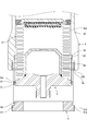
- FIG. 1 the front side in FIG. 1 will be referred to as the front side (front side) of the accumulator, and the description will be made with reference to the vertical and horizontal directions when viewed from the front side.
- the accumulator 1 is a metal bellows type accumulator that uses a metal bellows as the bellows body 31 and is used as a pressure accumulator, a pulsation damping device, or the like in an automotive hydraulic system, an industrial hydraulic system, or the like.
- the accumulator 1 is mainly composed of a housing 2 and a bellows 3 provided in the housing 2.
- FIG. 1 shows a state in which a bellows body 31 to be described later is extended by a pressure such as liquid storage.
- the bellows 3 is mainly composed of a metal bellows body 31 having a substantially cylindrical shape whose upper and lower ends are open, and a metal bellows cap 32 having a disk shape. ing.
- the bellows main body 31 has an outer diameter D1 smaller than an inner diameter d2 of an upper end side of a cylindrical portion 42 of the shell 4 and an inner diameter d4 of the opening 4a of the shell 4 (D1 ⁇ d2, d4: (See FIG. 1).
- the bellows body 31 is welded and fixed to the inner surface of an oil port member 5 (base body) described later (specifically, the welded portion 54a of the second annular convex portion 54), and the fixed end 31a (one end) constituting the lower end is closed.
- the lower surface 32a of the bellows cap 32 is welded and fixed while the annular protective ring 33 is sandwiched, and the floating end 31b constituting the upper end is closed.
- the protective ring 33 protects the bellows main body 31 from directly contacting the inner peripheral surface 42 a on the upper end side of the cylindrical portion 42 of the shell 4, and also the outer peripheral surface 33 a of the protective ring 33 and the cylindrical portion of the shell 4.
- the inner peripheral surface 42a of 42 is slightly spaced in the radial direction so that it can slide smoothly without obstructing the expansion and contraction operation of the bellows 3.
- a bellows cap 32 has a lower surface 32a fitted with a circular seal holder 34 having a crank shape in cross section.
- a disc-like seal member 35 is attached to and fixed to the seal holder 34. .
- the seal member 35 is configured by adhering (vulcanizing and adhering) a rubber-like elastic body 37 to a part or all of the surface of a base material 36 made of metal and having a disk shape.
- the housing 2 includes a bottomed cylindrical shell 4 having an opening 4 a at the lower end, and an oil port member 5 that seals the opening 4 a of the shell 4. Yes.
- the oil port member 5 is fixed to the shell 4 by a separate fixing member 6 in a state where the opening 4a of the shell 4 is sealed.
- the shell 4 is provided with a gas filling port 40 for injecting a high-pressure gas (for example, nitrogen gas) into a gas chamber 7 (described later) formed in the housing 2 at a position substantially in the center in the radial direction of the upper end portion.
- a gas filling port 40 for injecting a high-pressure gas (for example, nitrogen gas) into a gas chamber 7 (described later) formed in the housing 2 at a position substantially in the center in the radial direction of the upper end portion.
- the gas filling port 40 is closed by screwing the gas plug 41 after the high-pressure gas is injected.
- the O-ring 41 a made of a rubber-like elastic body is interposed between the gas plug 41 and the shell 4, whereby leakage of high-pressure gas in the gas chamber 7 of the housing 2 can be prevented.
- the cylindrical portion 42 of the shell 4 is configured such that the opening 4a side is thicker toward the outer diameter side, and the inner peripheral surface 43a on the opening 4a side is closer to the inner peripheral surface 42a on the upper end side of the cylindrical portion 42.
- a first annular recess 43 to which the oil port member 5 is attached is formed, and the fixing member 6 is attached to the inner peripheral surface 44a on the opening 4a side further than the first annular recess 43 (inner peripheral surface 43a).
- a second annular recess 44 is formed.
- the first annular recess 43 has an inner diameter d3 larger than the inner diameter d2 of the inner peripheral surface 42a on the upper end side of the cylindrical portion 42 of the shell 4 (the portion on which the outer peripheral surface 33a of the protective ring 33 of the bellows 3 slides). (D2 ⁇ d3: see FIG. 1). According to this, there is a cylindrical portion between the end on the opening 4a side of the inner peripheral surface 42a of the cylindrical portion 42 of the shell 4 and the end on the upper end side of the first annular recess 43 (inner peripheral surface 43a).
- a formed first annular step 45 (regulation step) is formed.
- the second annular recess 44 has an inner diameter d4 larger than the inner diameter d3 of the first annular recess 43 (d3 ⁇ d4: see FIG. 1).
- the inner diameter d4 of the second annular recess 44 is configured to have substantially the same dimension as the inner diameter d4 of the opening 4a of the shell 4. According to this, the end on the opening 4a side of the first annular recess 43 (inner peripheral surface 43a) of the cylindrical portion 42 of the shell 4 and the end on the upper end side of the second annular recess 44 (inner peripheral surface 44a).
- annular surface portion is formed in the radial direction due to a dimensional difference between the inner diameter d3 of the first annular recess 43 and the inner diameter d4 of the second annular recess 44, and a step shape substantially perpendicular to the cylindrical portion 42 of the shell 4 is formed.
- a second annular step 46 is formed.
- the second annular recess 44 is formed with a female screw portion 44b into which a male screw portion 61b formed on the fixing member 6 described later is screwed.
- the oil port member 5 is provided with a fluid inlet / outlet passage 50 (through hole) for penetrating in the axial direction (vertical direction) and for flowing a liquid (for example, hydraulic oil) from a pressure pipe (not shown) into the housing 2. ing.
- the oil port member 5 is provided with an annular mounting portion 51 having an inner diameter d3 of the first annular recess 43 formed in the cylindrical portion 42 of the shell 4 and an outer diameter D3 thereof having substantially the same dimensions.
- An O-ring 52 annular seal member made of a rubber-like elastic body is attached to an annular groove 51b formed on the outer peripheral surface 51a of the mounting portion 51 and recessed toward the inner diameter side.
- the mounting portion 51 is configured such that the outer diameter D3 is larger than the outer diameter D1 of the bellows body 31 (D1 ⁇ D3: see FIG. 1).
- the inner surface (upper surface) of the oil port member 5 protrudes upward from the mounting portion 51 (inside the housing 2), and the inner diameter d2 of the inner peripheral surface 42a on the upper end side of the cylindrical portion 42 of the shell 4 and its A first annular convex portion 53 configured to have substantially the same outer diameter D2 is formed.
- a second annular convex portion 54 protruding upward is formed on the inner diameter side of the first annular convex portion 53.
- the fixed end 31a of the bellows main body 31 is fixed by welding.
- a third annular convex portion 55 projecting upward is formed on the inner diameter side of the second annular convex portion 54, and a substantially U-shaped stay 56 facing downward in a sectional view is welded and fixed to the outer diameter side. .
- the stay 56 is provided with a through-hole 56a penetrating in the axial direction at a position substantially in the radial direction of the upper end portion, and an annular seal surface 56b is formed on the outer diameter side of the through-hole 56a.
- the internal space of the housing 2 is a structure in which the gas chamber 7 communicating with the gas filling port 40 and the liquid chamber 8 communicating with the fluid inlet / outlet path 50 are hermetically sealed by the bellows 3 (the bellows body 31 and the bellows cap 32). It has become.
- the gas chamber 7 is defined by the inner peripheral surface 42 a of the shell 4, the outer peripheral surface 31 c of the bellows body 31, and the upper surface 32 b of the bellows cap 32, and high-pressure gas injected from the gas sealing port 40 is sealed therein.
- the liquid chamber 8 is defined by the stay 56, the inner peripheral surface 31d of the bellows main body 31, and the lower surface 32a (seal holder 34, seal member 35) of the bellows cap 32, and the liquid flows out from the pressure pipe through the fluid inlet / outlet passage 50. It comes to enter.
- the accumulator 1 adjusts the pressure by moving the bellows cap 32 to a predetermined position by balancing and expanding the bellows 3 provided in the housing 2 to balance the gas pressure in the gas chamber 7 and the liquid pressure in the liquid chamber 8. Yes.
- the bellows cap 32 receives the gas pressure in the gas chamber 7 and moves downward, and the bellows main body 31 contracts, thereby the bellows cap 32.
- the seal member 35 attached to the lower surface 32a of the plate 56 and the seal surface 56b of the stay 56 are in close contact with each other to form an annular seal portion S1 (see FIG. 2), and the through hole 56a of the stay 56 is closed.
- the fixing member 6 is formed in an annular shape by providing a through hole 60 penetrating in the axial direction on the inner diameter side, and is formed in the cylindrical portion 42 of the shell 4.
- a male screw portion 61b is formed on the outer peripheral surface 61a of the mounting portion 61 having the inner diameter d4 of the recess 44 and the outer diameter D4 of which are approximately the same size.
- the outer diameter at the apex of the crest of the male thread 61b formed on the fixing member 6 is at the bottom of the valley of the female thread 44b of the second annular recess 44 formed on the cylindrical part 42 of the shell 4. It is configured to have substantially the same dimensions as the inner diameter.
- the upper surface of the fixing member 6 protrudes upward (from the oil port member 5 side) from the mounting portion 61 and has an inner diameter d3 and an outer diameter D3 of the first annular recess 43 formed in the cylindrical portion 42 of the shell 4. Are formed with substantially the same dimensions.
- the oil port member 5 to which the fixed end 31 a of the bellows main body 31 is fixed by welding is inserted from the opening 4 a of the shell 4 so that the bellows main body 31 is disposed inside the shell 4. .
- the inner surface (upper surface) of the mounting portion 51 of the oil port member 5 is brought into contact with the first annular step portion 45 formed in the cylindrical portion 42 of the shell 4 to be fitted into the first annular recess 43.
- the oil port member 5 is positioned in the axial direction with respect to the shell 4.
- an annular seal portion S2 is formed by the O-ring 52 being interposed between the outer peripheral surface 51a of the mounting portion 51 of the oil port member 5 and the first annular recess 43 (see FIGS. 1 and 2). .
- the male screw portion 61 b formed on the outer peripheral surface 61 a of the mounting portion 61 of the fixing member 6 is screwed into the female screw portion 44 b of the second annular recess 44 formed in the cylindrical portion 42 of the shell 4.
- the annular convex portion 62 of the fixing member 6 presses the mounting portion 51 of the oil port member 5 from the outer surface side (lower surface side), so that the outer peripheral portion of the mounting portion 51 of the oil port member 5 is the first of the shell 4. It can be fixed so as to be sandwiched between the annular step 45 and the annular projection 62 of the fixing member 6.
- the oil port member 5 is restricted from moving in the axial direction with respect to the shell 4 by the first annular step 45, the oil port member can be attached by attaching the fixing member 6 to the shell 4 (second annular recess 44). 5 is fixed at a predetermined position with respect to the shell 4.
- the outer diameter D1 of the bellows body 31 is smaller than the inner diameter d4 of the opening 4a of the shell 4 (D1 ⁇ d4: see FIG. 1), and the outer diameter D3 of the mounting portion 51 of the oil port member 5 is the bellows. Since the outer diameter D1 of the main body 31 is larger (D1 ⁇ D3: see FIG. 1), the bellows main body 31 welded and fixed to the oil port member 5 is inserted from the opening 4a of the shell 4 to fix the fixing member. 6, the oil port member 5 is detachably fixed to the shell 4, so that the bellows body 31 and the oil port member 5 can be attached to the shell 4, and the bellows body 31 and the oil from the opening 4 a of the shell 4.
- An annular seal portion S2 is formed by an O-ring 52 interposed between the outer peripheral surface 51a of the mounting portion 51 of the oil port member 5 and the first annular recess 43 of the shell 4, and the inside of the liquid chamber 8 of the housing 2 is formed. Liquid leakage can be prevented.
- the welded portion between the shell 4 and the oil port member 5 extends in the circumferential direction. It needs to be welded accurately. In this case, since the shell 4 and the oil port member 5 are in a welded state, they cannot be disassembled, and it is difficult to perform maintenance work such as replacement of the bellows body 31.
- annular seal portion S2 is formed by an O-ring 52 interposed between the outer peripheral surface 51a of the mounting portion 51 of the oil port member 5 and the first annular recess 43 of the shell 4. Since leakage of the liquid in the liquid chamber 8 of the housing 2 can be prevented, the sealing performance of the housing 2 can be improved without welding the shell 4 and the oil port member 5. Further, as described above, by opening the male screw portion 61b of the attachment portion 61 of the fixing member 6 to the female screw portion 44b of the second annular recess 44 of the shell 4, the opening portion 4a of the shell 4 is oiled.
- the oil port member 5 can be fixed to the shell 4 by the separate fixing member 6 that can hold the sealed state by the port member 5 and can be easily attached to and detached from the shell 4.
- the operation of fixing and disassembling the oil port member 5 with respect to 4 can be simplified, and the maintainability of the bellows body 31 can be improved.
- the oil port member 5 is fixed to the shell 4 by screw fixing of the fixing member 6 which is separate from the oil port member 5, the oil port member 5 is fixed when the fixing member 6 is fixed to the shell 4. Since it does not rotate together with the member 6, it is possible to prevent wear caused by rubbing the O-ring 52 between the outer peripheral surface 51 a of the mounting portion 51 of the oil port member 5 and the first annular recess 43 of the shell 4. .
- the oil port member 5 to which the bellows body 31 is fixed by welding is fixed to the shell 4 by screwing, not by welding. Therefore, the oil port member 5 is not deformed by heat when being fixed to the shell 4, and Residual stress generated in the oil port member 5 after fixing can be reduced.
- the gas plug 41 of the gas filling port 40 of the shell 4 is loosened to discharge the high-pressure gas in the gas chamber 7 and gas.
- the stress from the high-pressure gas does not act on the bellows body 31 and can be removed safely.
- the gas filling port 40 can seal the high-pressure gas injected into the gas chamber 7 by screwing the gas plug 41 again, the maintainability of the accumulator 1 can be improved.
- the oil port member 5 can be easily positioned with respect to the shell 4.
- the outer peripheral portion of the mounting portion 51 of the oil port member 5 is located between the first annular step 45 of the shell 4 and the annular convex portion 62 of the fixing member 6. Therefore, the oil port member 5 can be prevented from rotating relative to the shell 4. Furthermore, by fixing the fixing member 6 to the shell 4 with a screw, a stress that presses the outer peripheral portion of the mounting portion 51 of the oil port member 5 in the axial direction (on the first annular step portion 45 side) can be applied. Therefore, the oil port member 5 can be prevented from rotating with respect to the shell 4 when the accumulator 1 is used.
- the fixing member 6 is formed in an annular shape, the fixing member 6 is fixed to the shell 4 with a screw, thereby applying a stress that presses the outer peripheral portion of the mounting portion 51 of the oil port member 5 in the axial direction. It can work evenly. Moreover, it can be made lighter than a disk-shaped configuration.
- a second annular step 46 is formed between the first annular recess 43 and the second annular recess 44 on the inner peripheral surface 42 a of the cylindrical portion 42 of the shell 4, whereby the inner diameter of the first annular recess 43 is formed. Since the axial position of the annular convex portion 62 of the fixing member 6 having d3 and its outer diameter D3 having substantially the same dimensions is not restricted, the axial position of the oil port member 5 with respect to the shell 4 is set to an appropriate position. And can be fixed securely.
- the male screw portion 61 b formed on the outer peripheral surface 61 a of the mounting portion 61 of the fixing member 6 is made to have a female screw portion 44 b formed in the second annular recess 44 of the inner peripheral surface 42 a of the cylindrical portion 42 of the shell 4. Since the fixing member 6 can be arranged on the inner diameter side of the shell 4 by screwing, the structure for fixing the oil port member 5 to the shell 4 can be made compact.
- the oil port member 5 is configured so as to be key-fitted to the shell 4 (for example, the first annular step 45 of the shell 4 is provided with a recess that is a key groove extending in the axial direction, and the outer periphery of the oil port member 5 In this case, the relative rotation of the oil port member 5 with respect to the shell 4 is restricted by the key fitting, so that the protrusion with respect to the shell 4 is restricted.
- the fixing member 6 is fixed with the screw, the oil port member 5 rotates together, so that the O-ring 52 can be prevented from rotating and the sealing performance can be ensured.
- the accumulator 101 has a male screw portion 142 c formed on the opening 104 a side of the outer peripheral surface 142 b of the cylindrical portion 142 of the shell 104.
- An O-ring 147 made of a rubber-like elastic body is attached to an annular groove 142d formed on the outer peripheral surface 142b of the cylindrical portion 142 of the shell 104 and recessed toward the inner diameter side.
- the oil port member 105 is provided with a fluid inlet / outlet passage 150 penetrating in the axial direction.
- the accumulator 101 detachably connects the accumulator 101 to the housing by screwing the male screw portion 142c of the shell 104 into a female screw portion formed in a housing provided with a pressure pipe (not shown). be able to. Further, by interposing the O-ring 147 between the casing and the outer peripheral surface 142b of the cylindrical portion 142 of the shell 104, the accumulator 101 can be hermetically connected to the casing. Further, in a state where the accumulator 101 is hermetically connected to the housing, the liquid in the pressure pipe flows into and out of the housing 2 through the through hole 60 of the fixing member 6 and the fluid inlet / outlet path 150 of the oil port member 105. be able to.
- the accumulator 201 is provided with an annular convex portion 261 that protrudes from the outer surface side (lower surface side) of the mounting portion 251 of the oil port member 205 to the opening 204 a side of the shell 204.
- the annular convex portion 261 is configured so that the inner diameter and the outer diameter of the second annular concave portion 244 formed in the cylindrical portion 242 of the shell 204 are substantially the same, and a male screw portion 261b is formed on the outer peripheral surface 261a. . That is, the oil port member 5 and the fixing member 6 of Example 1 described above are integrally configured.
- the accumulator 201 is formed by screwing the male screw portion 261b formed in the annular convex portion 261 of the oil port member 205 with the female screw portion 244a formed in the second annular concave portion 244 of the shell 204. Since the opening 204a of 204 can be kept sealed by the oil port member 205, it is not necessary to separately prepare a fixing member for fixing the oil port member 205 to the shell 204. The fixing and disassembling work of the oil port member 205 is simplified, and the maintainability of the bellows body 31 can be improved.
- a female screw portion 342c is formed on the opening 304a side of the outer peripheral surface 342b of the cylindrical portion 342 of the shell 304.
- the fixing member 306 has a cup shape that opens upward by extending the attachment portion 361 so as to cover the opening 304a side of the shell 304 from the outer diameter side, and a through hole 360 that penetrates in the axial direction to the inner diameter side. Is provided to form an annular shape. Further, the mounting portion 361 is configured so that the outer diameter and the inner diameter of the female screw portion 342c formed on the outer peripheral surface 342b of the cylindrical portion 342 of the shell 304 have substantially the same dimensions, and the inner peripheral surface 361a of the mounting portion 361 includes A male screw portion 361b is formed.
- the upper surface of the fixing member 306 protrudes upward (from the oil port member 5 side) from the mounting portion 361, and the inner diameter and outer diameter of the first annular recess 343 formed in the cylindrical portion 342 of the shell 304 are approximately the same.
- An annular convex portion 362 having the same dimensions is formed.
- the accumulator 301 is threadedly engaged with a male screw portion 361b formed on the inner peripheral surface 361a of the attachment portion 361 of the fixing member 306 to a female screw portion 342c formed on the outer peripheral surface 342b of the cylindrical portion 342 of the shell 304.
- the state in which the opening 304a of the shell 304 is sealed by the oil port member 5 can be maintained, and the oil port member 5 can be held by a separate fixing member 306 that can be easily attached to and detached from the shell 304. Since the oil port member 5 can be fixed to the shell 304, the fixing and disassembling work of the oil port member 5 with respect to the shell 304 is simplified, and the maintainability of the bellows body 31 can be improved.
- the oil port member 5 can be fixed by being sandwiched between the first annular step portion 345 of the shell 304 and the annular convex portion 362 of the fixing member 306, On the other hand, the oil port member 5 can be fixed at a predetermined position, and the oil port member 5 can be prevented from rotating with respect to the shell 304.
- annular groove 444 a that is recessed toward the outer diameter side is formed in the second annular recess 444 of the cylindrical portion 442 of the shell 404.
- the oil port member 405 is provided with a protruding portion 461 that protrudes from the outer surface side (lower surface side) of the mounting portion 451 toward the opening 404 a side of the shell 404.
- the protruding portion 461 is configured so that the inner diameter and the outer diameter of the second annular recess 444 formed in the cylindrical portion 442 of the shell 404 are substantially the same size, and the inner surface (upper surface) is formed in the cylindrical portion 442 of the shell 404.
- the second annular step 446 is configured to be fitted into the second annular recess 444 in a state where the second annular step 446 is in contact with the second annular step 446.
- the fixing member 406 has a substantially C-shaped retaining ring shape, and has an outer diameter larger than the inner diameter of the second annular recess 444 formed in the shell 404 and is formed in the second annular recess 444 of the shell 404.
- the inner diameter of the groove portion 444a and the outer diameter thereof are configured to have substantially the same dimensions.
- the fixing member 406 is not limited to a substantially C shape as long as it has a retaining ring shape.
- the accumulator 401 fits the retaining ring-shaped fixing member 406 into the groove 444 a formed in the second annular recess 444 of the shell 404, so that the opening 404 a of the shell 404 is sealed by the oil port member 405.
- the oil port member 405 can be fixed to the shell 404 by a separate fixing member 406 that can be held in a fixed state and can be easily attached to and detached from the shell 404.
- the fixing / disassembling work of the member 405 is simplified, and the maintainability of the bellows main body 31 can be improved.
- the oil port member 405 can be fixed by being sandwiched between the second annular step portion 446 of the shell 404 and the fixing member 406, the oil port member is fixed to the shell 404. While fixing 405 at a predetermined position, the oil port member 405 can be prevented from rotating with respect to the shell 404.
- the accumulators 1, 101, 201, 301, 401 are so-called external gas type accumulators in which the gas chamber 7 is set outside the bellows 3 and the liquid chamber 8 is set inside the bellows 3.
- the present invention is not limited thereto, and for example, an internal gas type accumulator (see FIG. 8) may be used in which the liquid chamber 8 is set outside the bellows 3 and the gas chamber 7 is set inside the bellows.
- the housing 2 fixes the opening part 4a, 104a, 204a, 304a, 404a of the bottomed cylindrical shell 4,104,204,304,404 by the fixing member 6,306,406.
- the oil port members 5, 105, 405 or the fixing member is described as being sealed by the oil port member 205 integrally formed, the housing is not limited to this, and the upper and lower ends of the cylindrical shell that is open at both ends are used. These openings may be sealed by an oil port member and a gas sealing member fixed by a fixing means.
- the O-ring 52 is mounted on the groove 51b formed in the oil port members 5, 105, 205, and 405.
- An O-ring may be attached to the.
- the O-ring is not limited to the one interposed between the outer peripheral surface of the mounting portion of the oil port member and the first annular concave portion of the shell, but can seal the sealing performance between the shell and the oil port member. May be arranged freely.
- an O-ring may be attached to the fixing member.
- annular seal member is not limited to the O-ring and may be other seal members such as packing.
Landscapes
- Engineering & Computer Science (AREA)
- Physics & Mathematics (AREA)
- Fluid Mechanics (AREA)
- Mechanical Engineering (AREA)
- General Engineering & Computer Science (AREA)
- Supply Devices, Intensifiers, Converters, And Telemotors (AREA)
Abstract
金属ベローズのメンテナンス性が高められたアキュムレータを提供する。 開口部4aが設けられるシェル4と、開口部4aの内径d4よりもその外径D1が小さい金属ベローズ31の一端31aが溶接固定される円盤形の基部体5と、を有するハウジング2を備え、ハウジング2の内部が金属ベローズ31の内外で密閉状態に仕切られるアキュムレータ1であって、基部体5の外径D3は、金属ベローズ31の外径D1よりも大きく形成されているとともに、基部体5はシェル4に着脱可能に固定されている。
Description
本発明は、自動車用油圧システム、産業機器用油圧システム等において、蓄圧装置、脈動減衰装置等として用いられる金属ベローズ型のアキュムレータに関する。
自動車、産業機器等の油圧制御装置の油圧回路には、蓄圧、脈動の減衰(緩衝)等を行うためのアキュムレータが設けられている。このようなアキュムレータは、ハウジング内にベローズが配置され、ベローズは、固定端がハウジングに溶接固定された金属製のベローズ本体と、該ベローズ本体の他端に取付けられたベローズキャップと、から構成され、ベローズ本体およびベローズキャップにより、ハウジングの内部空間はガスを封入するガス室と、油圧回路に接続される流体出入路に通じる液室とに密閉状態に仕切られている。また、ベローズは、油圧回路から流体出入路を介して液室に流入する液体を受けてガス室内のガス圧と液室内の液体圧とが均衡するようにベローズ本体が伸縮して、蓄圧作動、脈動減衰作動等を行っている。
特許文献1に開示されているアキュムレータは、蓋体(基部体)および外殻部材(シェル)からなるハウジング内にベローズ機構(ベローズ)が配置され、ベローズ機構を構成する金属ベローズ(ベローズ本体)は、流体出入路が設けられる金属製の蓋体の内面に対して一端を溶接固定されている。また、蓋体は、金属ベローズが溶接固定された状態で、金属製の外殻部材の開口部分に形成される曲面部に対して外周部分を溶接固定され、外殻部材の開口部が蓋体により閉塞されることにより、ベローズ機構によってハウジングの内部空間がガス室と液室とに密閉状態に仕切られるようになっている。
しかしながら、特許文献1にあっては、ベローズ機構を構成する金属ベローズの一端が溶接固定される蓋体を外殻部材に対して押さえ込んだ状態で外殻部材の開口部を閉塞するように溶接固定されているため、固定作業が煩雑となるだけでなく、蓋体と外殻部材を容易に分解することができず、ハウジングの内部に配置されるベローズ機構のメンテナンスが困難になるという問題があった。
本発明は、このような問題点に着目してなされたもので、金属ベローズのメンテナンス性が高められたアキュムレータを提供することを目的とする。
前記課題を解決するために、本発明のアキュムレータは、
開口部が設けられるシェルと、前記開口部の内径よりもその外径が小さい金属ベローズの一端が溶接固定される円盤形の基部体と、を有するハウジングを備え、前記ハウジングの内部が前記金属ベローズの内外で密閉状態に仕切られるアキュムレータであって、
前記基部体の外径は、前記金属ベローズの外径よりも大きく形成されているとともに、
前記基部体は前記シェルに着脱可能に固定されていることを特徴としている。
この特徴によれば、シェルの開口部の内径が金属ベローズの外径よりも小さく、かつ基部体の外径が金属ベローズの外径よりも大きく形成されているため、基部体に溶接固定された金属ベローズをシェルの開口部から挿入して、基部体をシェルに着脱可能に固定することにより、シェルに対して金属ベローズと基部体を取付けることができるとともに、シェルの開口部から金属ベローズと基部体を一緒に引き出して取外すことができるため、金属ベローズのメンテナンス性を高めることができる。
前記シェルの内周面には、前記基部体の外周部が当接する規制段部が設けられていることを特徴としてもよい。
この特徴によれば、シェルの内周面に設けられる規制段部に基部体の外周部が当接することより、シェルの内部における基部体の挿入方向への移動を規制することができるため、シェルに対する基部体の位置決めを容易に行うことができる。
この特徴によれば、シェルの内周面に設けられる規制段部に基部体の外周部が当接することより、シェルの内部における基部体の挿入方向への移動を規制することができるため、シェルに対する基部体の位置決めを容易に行うことができる。
前記基部体の外周部と前記シェルの内周面との間には、環状シール部材が設けられ、
前記基部体を前記シェルに対して固定する該基部体とは別体の固定部材を備えることを特徴としてもよい。
この特徴によれば、シェルに対して基部体を取付けることにより、基部体の外周部とシェルの内周面との間に環状シール部材を介在させることができるため、ハウジング内の流体の漏れ出しを防止することができるとともに、シェルの内周面に設けられる規制段部に基部体の外周部を当接させて位置決めした状態で基部体とは別体の固定部材により固定することができるため、基部体をシェルに対して所定の位置に固定することができる。つまり、シール機能と固定機能とを個別に調整する構成であるため、溶接によらずとも確実にシール機能と固定機能を満たすことができる。
前記固定部材の外周部には、前記シェルの内周面に設けられる雌ネジ部に対して螺合可能な雄ネジ部が設けられていることを特徴としてもよい。
この特徴によれば、シェルの内周面に設けられる雌ネジ部に対して固定部材の外周部に設けられる雄ネジ部を螺合させることにより、固定部材によりシェルに対して基材を容易に固定することができる。
この特徴によれば、シェルの内周面に設けられる雌ネジ部に対して固定部材の外周部に設けられる雄ネジ部を螺合させることにより、固定部材によりシェルに対して基材を容易に固定することができる。
前記固定部材は、環状であることを特徴としてもよい。
この特徴によれば、固定部材は、環状であるため、シェルに対して基部体を均等に固定することができるとともに軽量とすることができる。
この特徴によれば、固定部材は、環状であるため、シェルに対して基部体を均等に固定することができるとともに軽量とすることができる。
前記基部体には、前記金属ベローズの内部に連通する貫通孔が設けられることを特徴としてもよい。
この特徴によれば、基部体に設けられる貫通孔を通して金属ベローズの内部に流体を流入または流出させることができるため、基部体をオイルポートまたはガスポートとして使用することができる。
この特徴によれば、基部体に設けられる貫通孔を通して金属ベローズの内部に流体を流入または流出させることができるため、基部体をオイルポートまたはガスポートとして使用することができる。
前記基部体は、前記シェルに対してキー嵌合することを特徴としてもよい。
この特徴によれば、基部体がシェルに対してキー嵌合することにより、シェルに対して基部体を回転止めすることができるため、固定部材を螺合させてシェルに対して基部体を固定する際の環状シール部材の回動が防止され、環状シール部材のシール性を確保することができる。
この特徴によれば、基部体がシェルに対してキー嵌合することにより、シェルに対して基部体を回転止めすることができるため、固定部材を螺合させてシェルに対して基部体を固定する際の環状シール部材の回動が防止され、環状シール部材のシール性を確保することができる。
本発明に係るアキュムレータを実施するための形態を実施例に基づいて以下に説明する。
実施例1に係るアキュムレータにつき、図1から図3を参照して説明する。以下、図1の紙面手前側をアキュムレータの正面側(前方側)とし、その前方側から見たときの上下左右方向を基準として説明する。
アキュムレータ1は、例えば自動車用油圧システム、産業機器用油圧システム等において、蓄圧装置、脈動減衰装置等として用いられるものであり、ベローズ本体31として金属ベローズを用いた金属ベローズ型のアキュムレータである。
図1に示されるように、アキュムレータ1は、ハウジング2と、ハウジング2内に設けられるベローズ3と、から主に構成されている。尚、図1は、蓄液等の圧力により後述するベローズ本体31が伸長した状態を示している。
先ず、ベローズ3の構造について詳しく説明する。図1および図2に示されるように、ベローズ3は、上下両端が開放する略円筒状を成す金属製のベローズ本体31と、円盤状を成す金属製のベローズキャップ32と、から主に構成されている。尚、ベローズ本体31は、後述するシェル4の円筒部42の上端側の内径d2およびシェル4の開口部4aの内径d4よりもその外径D1が小さく構成されている(D1<d2,d4:図1参照)。
ベローズ本体31は、後述するオイルポート部材5(基部体)の内面(詳しくは第2環状凸部54の溶接部54a)に溶接固定されて下端を構成する固定端31a(一端)が閉塞されるとともに、環状の保護リング33を挟着した状態でベローズキャップ32の下面32aが溶接固定されて上端を構成する遊動端31bが閉塞されている。
尚、保護リング33は、シェル4の円筒部42の上端側の内周面42aに対して直接ベローズ本体31が接触しないように保護するとともに、保護リング33の外周面33aとシェル4の円筒部42の内周面42aとは、径方向に僅かに離間しており、ベローズ3の伸縮作動を妨げることなく滑らかに摺動できるようになっている。
また、ベローズキャップ32の下面32aには、断面視クランク形状の環状を成すシールホルダ34が嵌合されており、該シールホルダ34に対して円盤状を成すシール部材35が取付け、固定されている。
シール部材35は、金属製で円板状を成す基材36の表面の一部または全部にゴム状弾性体37を被着(加硫接着)させることにより構成されている。
次いで、ハウジング2の構造について詳しく説明する。図1および図2に示されるように、ハウジング2は、下端に開口部4aを有する有底円筒状のシェル4と、シェル4の開口部4aをシールするオイルポート部材5と、から構成されている。尚、オイルポート部材5は、シェル4の開口部4aをシールした状態で別体の固定部材6によりシェル4に固定されている。
シェル4には、上端部の径方向略中央の位置にハウジング2内に形成される後述するガス室7に高圧ガス(例えば窒素ガス)を注入するためのガス封入口40が設けられている。尚、ガス封入口40は、高圧ガスの注入後にガスプラグ41がネジ固定されることにより閉塞される。このとき、ガスプラグ41とシェル4との間にゴム状弾性体から構成されるOリング41aが介在することにより、ハウジング2のガス室7内の高圧ガスの漏れ出しを防止することができる。
また、シェル4の円筒部42は、開口部4a側が外径側に向かって厚肉に構成され、円筒部42の上端側の内周面42aよりも開口部4a側の内周面43aには、オイルポート部材5が取付けられる第1環状凹部43が形成され、該第1環状凹部43(内周面43a)よりもさらに開口部4a側の内周面44aには、固定部材6が取付けられる第2環状凹部44が形成されている。
第1環状凹部43は、シェル4の円筒部42の上端側の内周面42a(前述したベローズ3の保護リング33の外周面33aが摺動する部分)の内径d2よりもその内径d3を大きく構成されている(d2<d3:図1参照)。これによれば、シェル4の円筒部42の内周面42aの開口部4a側の端部と第1環状凹部43(内周面43a)の上端側の端部との間には、円筒部42の上端側の内周面42aの内径d2と第1環状凹部43の内径d3との寸法差により、径方向に環状の面部が構成され、シェル4の円筒部42に略直角の階段状を成す第1環状段部45(規制段部)が形成されている。
第2環状凹部44は、第1環状凹部43の内径d3よりもその内径d4を大きく構成されている(d3<d4:図1参照)。尚、第2環状凹部44の内径d4は、シェル4の開口部4aの内径d4と略同一寸法に構成されている。これによれば、シェル4の円筒部42の第1環状凹部43(内周面43a)の開口部4a側の端部と第2環状凹部44(内周面44a)の上端側の端部との間には、第1環状凹部43の内径d3と第2環状凹部44の内径d4との寸法差により、径方向に環状の面部が構成され、シェル4の円筒部42に略直角の階段状を成す第2環状段部46が形成されている。また、第2環状凹部44には、後述する固定部材6に形成される雄ネジ部61bが螺合される雌ネジ部44bが形成されている。
オイルポート部材5には、軸方向(上下方向)に貫通し、ハウジング2内に図示しない圧力配管から液体(例えば作動油)の流出入を行うための流体出入路50(貫通孔)が設けられている。
また、オイルポート部材5には、シェル4の円筒部42に形成される第1環状凹部43の内径d3とその外径D3を略同一寸法に構成される環状の取付部51が設けられ、該取付部51の外周面51aに形成され内径側に凹む環状の溝部51bには、ゴム状弾性体から構成されるOリング52(環状シール部材)が装着されている。尚、取付部51は、ベローズ本体31の外径D1よりもその外径D3が大きく構成されている(D1<D3:図1参照)。
また、オイルポート部材5の内面(上面)には、取付部51から上方(ハウジング2の内部側)に向けて突出し、シェル4の円筒部42の上端側の内周面42aの内径d2とその外径D2を略同一寸法に構成される第1環状凸部53が形成されており、第1環状凸部53の内径側には、上方に向けて突出する第2環状凸部54が形成され、前述したベローズ本体31の固定端31aが溶接固定されている。さらに、第2環状凸部54の内径側には、上方に向けて突出する第3環状凸部55が形成され、外径側に断面視下向き略コ字状のステー56が溶接固定されている。
ステー56には、上端部の径方向略中央の位置に軸方向に貫通する貫通孔56aが設けられ、貫通孔56aの外径側に環状のシール面56bが形成されている。
ハウジング2の内部空間は、ベローズ3(ベローズ本体31およびベローズキャップ32)によりガス封入口40と連通するガス室7と、流体出入路50と連通する液室8とに密閉状態に仕切られた構造となっている。
ガス室7は、シェル4の内周面42a、ベローズ本体31の外周面31cおよびベローズキャップ32の上面32bから画成され、ガス封入口40から注入される高圧ガスが封入されている。
液室8は、ステー56、ベローズ本体31の内周面31dおよびベローズキャップ32の下面32a(シールホルダ34,シール部材35)から画成され、流体出入路50を介して圧力配管から液体が流出入するようになっている。
アキュムレータ1は、ハウジング2内に設けられるベローズ3の伸縮作動により、ベローズキャップ32を所定位置に移動させてガス室7のガス圧と液室8の液体圧とを均衡させて圧力調整を行っている。
例えば、図2に示されるように、圧力配管内の液体が排出されると、ベローズキャップ32がガス室7のガス圧を受けて下方に移動しベローズ本体31が収縮することにより、ベローズキャップ32の下面32aに取付けられたシール部材35とステー56のシール面56bとが密接して環状のシール部S1(図2参照)を形成し、ステー56の貫通孔56aが閉塞される。これにより、液室8内に一部の液体が閉じ込められ、この閉じ込められた液体の圧力とガス室7のガス圧とが均衡するため、ベローズ本体31に過大な応力がかかることがなくなり、ベローズ本体31の破損を抑制できるようになっている。
次いで、固定部材6の構造について詳しく説明する。図1および図2に示されるように、固定部材6は、内径側に軸方向に貫通する貫通孔60が設けられることにより環状に構成され、シェル4の円筒部42に形成される第2環状凹部44の内径d4とその外径D4を略同一寸法に構成される取付部61の外周面61aには、雄ネジ部61bが形成されている。尚、固定部材6に形成される雄ネジ部61bの山部の頂点における外径は、シェル4の円筒部42に形成される第2環状凹部44の雌ネジ部44bの谷部の底点における内径と略同一寸法に構成されている。
また、固定部材6の上面には、取付部61から上方(オイルポート部材5側)に向けて突出し、シェル4の円筒部42に形成される第1環状凹部43の内径d3とその外径D3を略同一寸法に構成される環状凸部62が形成されている。
次いで、固定部材6によりシェル4に対してオイルポート部材5を固定する方法について詳しく説明する。図3に示されるように、先ず、ベローズ本体31の固定端31aが溶接固定されたオイルポート部材5をシェル4の開口部4aからベローズ本体31がシェル4の内部に配置されるように挿入する。具体的には、シェル4の円筒部42に形成される第1環状段部45にオイルポート部材5の取付部51の内面(上面)を当接させて第1環状凹部43に嵌合させることにより、オイルポート部材5はシェル4に対する軸方向の位置決めがなされる。このとき、オイルポート部材5の取付部51の外周面51aと第1環状凹部43との間にOリング52が介在することにより環状のシール部S2が形成される(図1および図2参照)。
次に、固定部材6の取付部61の外周面61aに形成される雄ネジ部61bをシェル4の円筒部42に形成される第2環状凹部44の雌ネジ部44bに螺合させる。このとき、固定部材6の環状凸部62がオイルポート部材5の取付部51を外面側(下面側)から押圧することにより、オイルポート部材5の取付部51の外周部をシェル4の第1環状段部45と固定部材6の環状凸部62との間に挟み込むようにして固定することができる。また、オイルポート部材5は、第1環状段部45によりシェル4に対する軸方向の移動が規制されているため、固定部材6をシェル4(第2環状凹部44)に取付けることにより、オイルポート部材5はシェル4に対して所定の位置に固定される。
これによれば、ベローズ本体31の外径D1がシェル4の開口部4aの内径d4よりも小さく(D1<d4:図1参照)、かつオイルポート部材5の取付部51の外径D3がベローズ本体31の外径D1よりも大きく(D1<D3:図1参照)形成されているため、オイルポート部材5に溶接固定されたベローズ本体31をシェル4の開口部4aから挿入して、固定部材6によりオイルポート部材5をシェル4に着脱可能に固定することにより、シェル4に対してベローズ本体31とオイルポート部材5を取付けることができるとともに、シェル4の開口部4aからベローズ本体31とオイルポート部材5を一緒に引き出して取外すことができるため、ベローズ本体31のメンテナンス性を高めることができる。また、オイルポート部材5の取付部51の外周面51aとシェル4の第1環状凹部43との間に介在するOリング52により環状のシール部S2が形成され、ハウジング2の液室8内の液体の漏れ出しを防止することができる。
具体的には、例えば、従来技術のように、金属ベローズ型のアキュムレータ1において、シェル4の円筒部42に形成される第2環状凹部44に対してオイルポート部材5の取付部51の外周面51aを溶接固定することにより、シェル4の開口部4aをシールするような場合、ハウジング2のシール性を確保するためには、シェル4とオイルポート部材5との溶接部分が周方向に亘って正確に溶接される必要がある。この場合、シェル4とオイルポート部材5とが溶接された状態となっているため、分解することができず、ベローズ本体31の交換等のメンテナンス作業を行うことが困難となっていた。
一方、本実施例のアキュムレータ1は、オイルポート部材5の取付部51の外周面51aとシェル4の第1環状凹部43との間に介在するOリング52により環状のシール部S2が形成され、ハウジング2の液室8内の液体の漏れ出しを防止することができるため、シェル4とオイルポート部材5とを溶接することなく、ハウジング2のシール性を高めることができる。さらに、上述したように、固定部材6の取付部61の雄ネジ部61bをシェル4の第2環状凹部44の雌ネジ部44bに対して螺合させることにより、シェル4の開口部4aがオイルポート部材5によりシールされた状態を保持することができ、シェル4に対して容易に着脱可能な別体の固定部材6によってオイルポート部材5をシェル4に対して固定することができるため、シェル4に対するオイルポート部材5の固定・分解作業が簡略化され、ベローズ本体31のメンテナンス性を高めることができる。
また、オイルポート部材5のシェル4に対する固定がオイルポート部材5とは別体の固定部材6のネジ固定により行われることから、シェル4に対する固定部材6のネジ固定時に、オイルポート部材5が固定部材6と一緒に回転することがないため、オイルポート部材5の取付部51の外周面51aとシェル4の第1環状凹部43との間でOリング52が擦れることによる摩耗を防ぐことができる。
さらに、ベローズ本体31が溶接固定されたオイルポート部材5のシェル4に対する固定は、溶接ではなくネジ固定で行われるため、オイルポート部材5にはシェル4に対する固定時に熱による変形が生じず、かつ固定後にオイルポート部材5に生じる残留応力を小さくすることができる。
また、シェル4の開口部4aからベローズ本体31およびオイルポート部材5を取外す際には、先ず、シェル4のガス封入口40のガスプラグ41を緩めてガス室7内の高圧ガスを排出させガス室7内のガス圧を低下させた状態とすることで、ベローズ本体31に高圧ガスからの応力が作用しなくなるため、安全に取外すことができる。さらに、ガス封入口40は、ガスプラグ41を再度ネジ固定することによりガス室7に注入した高圧ガスを封止することができるため、アキュムレータ1のメンテナンス性を高めることができる。
また、シェル4の円筒部42に形成される第1環状段部45にオイルポート部材5の取付部51の外周部における内面(上面)を当接させることにより、オイルポート部材5の軸方向(挿入方向)への移動を規制することができるため、シェル4に対するオイルポート部材5の位置決めを容易に行うことができる。
また、固定部材6をシェル4に対してネジ固定することにより、オイルポート部材5の取付部51の外周部をシェル4の第1環状段部45と固定部材6の環状凸部62との間に挟み込むようにして固定することができるため、シェル4に対してオイルポート部材5を回転止めすることができる。さらに、固定部材6をシェル4に対してネジ固定することにより、オイルポート部材5の取付部51の外周部に対して軸方向(第1環状段部45側)に押し付ける応力を作用させることができるため、アキュムレータ1の使用時にシェル4に対してオイルポート部材5を回転止めすることができる。
また、固定部材6は、環状に構成されているため、固定部材6をシェル4に対してネジ固定することにより、オイルポート部材5の取付部51の外周部に対して軸方向に押し付ける応力を均等に作用させることができる。また、円盤状の構成に比べ軽量とすることができる。
また、シェル4の円筒部42の内周面42aにおいて、第1環状凹部43と第2環状凹部44との間に第2環状段部46が形成されることにより、第1環状凹部43の内径d3とその外径D3を略同一寸法に構成される固定部材6の環状凸部62の軸方向位置が規制されることがなくなるため、シェル4に対するオイルポート部材5の軸方向位置を適切な位置に、かつ確実に固定することができる。
また、固定部材6の取付部61の外周面61aに形成される雄ネジ部61bをシェル4の円筒部42の内周面42aの第2環状凹部44に形成される雌ネジ部44bに対して螺合させることにより、固定部材6をシェル4の内径側に配置することができるため、シェル4に対するオイルポート部材5の固定構造をコンパクトに構成することができる。
尚、オイルポート部材5は、シェル4に対してキー嵌合するように構成(例えばシェル4の第1環状段部45に軸方向に延びるキー溝である凹部を設け、オイルポート部材5の外周部に軸方向に延びるキーである凸条を嵌合するように構成)されてもよく、この場合、キー嵌合によりシェル4に対するオイルポート部材5の相対回転が規制されるため、シェル4に対する固定部材6のネジ固定時に、オイルポート部材5が一緒に回転することとなり、Oリング52の回動を防止してシール性を確保することができる。
次に、実施例2に係るアキュムレータにつき、図4を参照して説明する。尚、前記実施例に示される構成部分と同一構成部分に付いては同一符号を付して重複する説明を省略する。
図4に示されるように、実施例2におけるアキュムレータ101は、シェル104の円筒部142の外周面142bの開口部104a側に雄ネジ部142cが形成されている。また、シェル104の円筒部142の外周面142bに形成され内径側に凹む環状の溝部142dには、ゴム状弾性体から構成されるOリング147が装着されている。
オイルポート部材105には、軸方向に貫通する流体出入路150が設けられている。
そのため、アキュムレータ101は、図示しない圧力配管が設けられる筐体に形成される雌ネジ部にシェル104の雄ネジ部142cを螺合させることにより、アキュムレータ101を筐体に対して着脱可能に接続することができる。また、筐体とシェル104の円筒部142の外周面142bとの間にOリング147を介在させることにより、アキュムレータ101を筐体に対して密閉状に接続することができる。さらに、アキュムレータ101が筐体に対して密閉状に接続された状態において、圧力配管内の液体を固定部材6の貫通孔60およびオイルポート部材105の流体出入路150を通してハウジング2内へ流出入させることができる。
次に、実施例3に係るアキュムレータにつき、図5を参照して説明する。尚、前記実施例に示される構成部分と同一構成部分に付いては同一符号を付して重複する説明を省略する。
図5に示されるように、実施例2におけるアキュムレータ201は、オイルポート部材205の取付部251の外面側(下面側)からシェル204の開口部204a側に突出する環状凸部261が設けられている。環状凸部261は、シェル204の円筒部242に形成される第2環状凹部244の内径とその外径を略同一寸法に構成され、その外周面261aには雄ネジ部261bが形成されている。すなわち、前述した実施例1のオイルポート部材5と固定部材6とが一体に構成されている。
そのため、アキュムレータ201は、オイルポート部材205の環状凸部261に形成される雄ネジ部261bをシェル204の第2環状凹部244に形成される雌ネジ部244aに対して螺合させることにより、シェル204の開口部204aがオイルポート部材205によりシールされた状態を保持することができるため、シェル204に対してオイルポート部材205を固定するために固定部材を別途用意する必要がなくなり、シェル204に対するオイルポート部材205の固定・分解作業が簡略化され、ベローズ本体31のメンテナンス性を高めることができる。
次に、実施例4に係るアキュムレータにつき、図6を参照して説明する。尚、前記実施例に示される構成部分と同一構成部分に付いては同一符号を付して重複する説明を省略する。
図6に示されるように、実施例4におけるアキュムレータ301は、シェル304の円筒部342の外周面342bの開口部304a側に雌ネジ部342cが形成されている。
固定部材306は、シェル304の開口部304a側を外径側から覆うように取付部361が延出することにより上向きに開口するカップ形状を成し、内径側に軸方向に貫通する貫通孔360が設けられることにより環状に構成されている。また、取付部361は、シェル304の円筒部342の外周面342bに形成される雌ネジ部342cの外径とその内径を略同一寸法に構成され、取付部361の内周面361aには、雄ネジ部361bが形成されている。
また、固定部材306の上面には、取付部361から上方(オイルポート部材5側)に向けて突出し、シェル304の円筒部342に形成される第1環状凹部343の内径とその外径を略同一寸法に構成される環状凸部362が形成されている。
そのため、アキュムレータ301は、固定部材306の取付部361の内周面361aに形成される雄ネジ部361bをシェル304の円筒部342の外周面342bに形成される雌ネジ部342cに対して螺合させることにより、シェル304の開口部304aがオイルポート部材5によりシールされた状態を保持することができるとともに、シェル304に対して容易に着脱可能な別体の固定部材306によってオイルポート部材5をシェル304に対して固定することができるため、シェル304に対するオイルポート部材5の固定・分解作業が簡略化され、ベローズ本体31のメンテナンス性を高めることができる。
また、オイルポート部材5の取付部51の外周部をシェル304の第1環状段部345と固定部材306の環状凸部362との間に挟み込むようにして固定することができるため、シェル304に対してオイルポート部材5を所定の位置に固定するとともに、シェル304に対してオイルポート部材5を回転止めすることができる。
次に、実施例5に係るアキュムレータにつき、図7を参照して説明する。尚、前記実施例に示される構成部分と同一構成部分に付いては同一符号を付して重複する説明を省略する。
図7に示されるように、実施例5におけるアキュムレータ401は、シェル404の円筒部442の第2環状凹部444に外径側に凹む環状の溝部444aが形成されている。
オイルポート部材405は、取付部451の外面側(下面側)からシェル404の開口部404a側に突出する突出部461が設けられている。突出部461は、シェル404の円筒部442に形成される第2環状凹部444の内径とその外径を略同一寸法に構成されるとともに、内面(上面)をシェル404の円筒部442に形成される第2環状段部446に当接させた状態において、第2環状凹部444に嵌合するように構成されている。
固定部材406は、略C字の止め輪形状を成し、シェル404に形成される第2環状凹部444の内径よりもその外径が大きく、かつシェル404の第2環状凹部444に形成される溝部444aの内径とその外径を略同一寸法に構成されている。尚、固定部材406は、止め輪形状を成すものであれば、略C字のものに限らない。
そのため、アキュムレータ401は、止め輪形状の固定部材406をシェル404の第2環状凹部444に形成される溝部444aに対して嵌合させることにより、シェル404の開口部404aがオイルポート部材405によりシールされた状態を保持することができるとともに、シェル404に対して容易に着脱可能な別体の固定部材406によってオイルポート部材405をシェル404に対して固定することができるため、シェル404に対するオイルポート部材405の固定・分解作業が簡略化され、ベローズ本体31のメンテナンス性を高めることができる。
また、オイルポート部材405の突出部461の外周部をシェル404の第2環状段部446と固定部材406との間に挟み込むようにして固定することができるため、シェル404に対してオイルポート部材405を所定の位置に固定するとともに、シェル404に対してオイルポート部材405を回転止めすることができる。
以上、本発明の実施例を図面により説明してきたが、具体的な構成はこれら実施例に限られるものではなく、本発明の要旨を逸脱しない範囲における変更や追加があっても本発明に含まれる。
例えば、前記実施例では、アキュムレータ1,101,201,301,401は、ベローズ3の外側にガス室7を設定するとともに、ベローズ3の内側に液室8が設定されるいわゆる外ガスタイプのアキュムレータとして説明したが、これに限らず、例えば、ベローズ3の外側に液室8を設定するとともに、ベローズの内側にガス室7を設定する内ガスタイプのアキュムレータ(図8参照)としてもよい。
また、前記実施例では、ハウジング2は、有底円筒状のシェル4,104,204,304,404の開口部4a,104a,204a,304a,404aを固定部材6,306,406によって固定されるオイルポート部材5,105,405または固定部材が一体に構成されるオイルポート部材205によりシールするものとして説明したが、これに限らず、ハウジングは、両端が開口する円筒状のシェルの上端および下端の開口部を固定手段により固定されるオイルポート部材およびガス封入部材によりそれぞれシールされるものであってもよい。
また、前記実施例では、オイルポート部材5,105,205,405に形成される溝部51bにOリング52が装着される態様として説明したが、シェルの円筒部の内周面に形成される溝部にOリングが装着されていてもよい。さらに、Oリングは、オイルポート部材の取付部の外周面とシェルの第1環状凹部との間に介在するものに限らず、シェルとオイルポート部材との間のシール性を確保できるものであれば自由に配置されてよい。例えば、固定部材にOリングが装着されていてもよい。
また、環状シール部材は、Oリングに限らずパッキン等の他のシール部材であってもよい。
1 アキュムレータ
2 ハウジング
3 ベローズ
4 シェル
4a 開口部
5 オイルポート部材(基部体)
6 固定部材
7 ガス室
8 液室
31 ベローズ本体
31a 固定端(一端)
42 円筒部
42a 内周面
43 第1環状凹部
43a 内周面
44 第2環状凹部
44a 内周面
44a 雌ネジ部
45 第1環状段部(規制段部)
46 第2環状段部
50 流体出入路(貫通孔)
51 取付部
51a 外周面
51b 溝部
52 Oリング(環状シール部材)
54 第2環状凸部
54a 溶接部
61 取付部
61a 外周面
61b 雄ネジ部
62 環状凸部
S1,S2 シール部
2 ハウジング
3 ベローズ
4 シェル
4a 開口部
5 オイルポート部材(基部体)
6 固定部材
7 ガス室
8 液室
31 ベローズ本体
31a 固定端(一端)
42 円筒部
42a 内周面
43 第1環状凹部
43a 内周面
44 第2環状凹部
44a 内周面
44a 雌ネジ部
45 第1環状段部(規制段部)
46 第2環状段部
50 流体出入路(貫通孔)
51 取付部
51a 外周面
51b 溝部
52 Oリング(環状シール部材)
54 第2環状凸部
54a 溶接部
61 取付部
61a 外周面
61b 雄ネジ部
62 環状凸部
S1,S2 シール部
Claims (7)
- 開口部が設けられるシェルと、前記開口部の内径よりもその外径が小さい金属ベローズの一端が溶接固定される円盤形の基部体と、を有するハウジングを備え、前記ハウジングの内部が前記金属ベローズの内外で密閉状態に仕切られるアキュムレータであって、
前記基部体の外径は、前記金属ベローズの外径よりも大きく形成されているとともに、
前記基部体は前記シェルに着脱可能に固定されていることを特徴とするアキュムレータ。 - 前記シェルの内周面には、前記基部体の外周部が当接する規制段部が設けられていることを特徴とする請求項1に記載のアキュムレータ。
- 前記基部体の外周部と前記シェルの内周面との間には、環状シール部材が設けられ、
前記基部体を前記シェルに対して固定する該基部体とは別体の固定部材を備えることを特徴とする請求項1または2に記載のアキュムレータ。 - 前記固定部材の外周部には、前記シェルの内周面に設けられる雌ネジ部に対して螺合可能な雄ネジ部が設けられていることを特徴とする請求項3に記載のアキュムレータ。
- 前記固定部材は、環状であることを特徴とする請求項3または4に記載のアキュムレータ。
- 前記基部体には、前記金属ベローズの内部に連通する貫通孔が設けられることを特徴とする請求項1ないし5のいずれかに記載のアキュムレータ。
- 前記基部体は、前記シェルに対してキー嵌合することを特徴とする請求項1ないし6のいずれかに記載のアキュムレータ。
Priority Applications (4)
| Application Number | Priority Date | Filing Date | Title |
|---|---|---|---|
| US16/605,777 US11047399B2 (en) | 2017-05-11 | 2018-04-27 | Accumulator |
| CN201880030113.2A CN110603383B (zh) | 2017-05-11 | 2018-04-27 | 蓄能器 |
| EP18799120.3A EP3623642B1 (en) | 2017-05-11 | 2018-04-27 | Accumulator |
| JP2019517566A JP6974449B2 (ja) | 2017-05-11 | 2018-04-27 | アキュムレータ |
Applications Claiming Priority (2)
| Application Number | Priority Date | Filing Date | Title |
|---|---|---|---|
| JP2017-094401 | 2017-05-11 | ||
| JP2017094401 | 2017-05-11 |
Publications (1)
| Publication Number | Publication Date |
|---|---|
| WO2018207654A1 true WO2018207654A1 (ja) | 2018-11-15 |
Family
ID=64105286
Family Applications (1)
| Application Number | Title | Priority Date | Filing Date |
|---|---|---|---|
| PCT/JP2018/017126 WO2018207654A1 (ja) | 2017-05-11 | 2018-04-27 | アキュムレータ |
Country Status (5)
| Country | Link |
|---|---|
| US (1) | US11047399B2 (ja) |
| EP (1) | EP3623642B1 (ja) |
| JP (1) | JP6974449B2 (ja) |
| CN (1) | CN110603383B (ja) |
| WO (1) | WO2018207654A1 (ja) |
Cited By (1)
| Publication number | Priority date | Publication date | Assignee | Title |
|---|---|---|---|---|
| US11761507B2 (en) | 2021-02-10 | 2023-09-19 | DRiV Automotive Inc. | Weight optimized bellow accumulator |
Families Citing this family (2)
| Publication number | Priority date | Publication date | Assignee | Title |
|---|---|---|---|---|
| JP6702905B2 (ja) * | 2017-03-13 | 2020-06-03 | 日本発條株式会社 | アキュムレータ |
| JP6975085B2 (ja) * | 2018-03-29 | 2021-12-01 | 日本発條株式会社 | アキュムレータの外殻部材及びその製造方法、並びに、アキュムレータ及びその製造方法 |
Citations (4)
| Publication number | Priority date | Publication date | Assignee | Title |
|---|---|---|---|---|
| US2561957A (en) * | 1947-10-13 | 1951-07-24 | Bendix Aviat Corp | Gas to hydraulic pressure transmitter or accumulator |
| JPS49100472A (ja) * | 1972-09-07 | 1974-09-24 | ||
| JPH0932801A (ja) * | 1995-07-19 | 1997-02-04 | Nobuyuki Sugimura | アキュムレータの隔膜支持装置 |
| JP2010174985A (ja) | 2009-01-29 | 2010-08-12 | Nhk Spring Co Ltd | アキュムレータへのガス封入方法 |
Family Cites Families (15)
| Publication number | Priority date | Publication date | Assignee | Title |
|---|---|---|---|---|
| US2365994A (en) * | 1944-03-22 | 1944-12-26 | Electrol Inc | Accumulator |
| GB1000744A (en) * | 1960-11-10 | 1965-08-11 | Plessey Co Ltd | Improvements in or relating to hydraulic accumulators |
| FR1391050A (fr) * | 1964-01-17 | 1965-03-05 | Rech Etudes Production Sarl | Accumulateur hydropneumatique de sécurité, applicable notamment aux circuits hydrauliques des aérodynes |
| JPS6340641Y2 (ja) * | 1980-12-09 | 1988-10-24 | ||
| JPS5798396A (en) | 1980-12-12 | 1982-06-18 | Pilot Ink Co Ltd | Method of sealing ball pen chip |
| JP3434303B2 (ja) * | 1992-06-08 | 2003-08-04 | 日本発条株式会社 | アキュムレータ装置 |
| JP4718129B2 (ja) * | 2003-07-30 | 2011-07-06 | 日本発條株式会社 | 車両用ブレーキシステム部品 |
| DE102004004341A1 (de) | 2004-01-29 | 2005-08-18 | Hydac Technology Gmbh | Druckspeicher, insbesondere Pulsationsdämpfer |
| JP4272604B2 (ja) * | 2004-08-23 | 2009-06-03 | 日本発條株式会社 | 圧力容器及び蓄圧・緩衝装置 |
| CN100376807C (zh) | 2006-07-12 | 2008-03-26 | 三一重工股份有限公司 | 活塞式蓄能器 |
| JP5102576B2 (ja) | 2007-10-10 | 2012-12-19 | Nok株式会社 | アキュムレータ |
| JP5474333B2 (ja) * | 2008-11-05 | 2014-04-16 | イーグル工業株式会社 | アキュムレータ |
| JP5374435B2 (ja) | 2010-04-20 | 2013-12-25 | イーグル工業株式会社 | アキュムレータ |
| JP5872342B2 (ja) * | 2012-03-22 | 2016-03-01 | イーグル工業株式会社 | アキュムレータ |
| JP6271353B2 (ja) | 2014-06-26 | 2018-01-31 | イーグル工業株式会社 | 電流遮断装置とそれを用いた蓄電装置 |
-
2018
- 2018-04-27 WO PCT/JP2018/017126 patent/WO2018207654A1/ja unknown
- 2018-04-27 US US16/605,777 patent/US11047399B2/en active Active
- 2018-04-27 EP EP18799120.3A patent/EP3623642B1/en active Active
- 2018-04-27 CN CN201880030113.2A patent/CN110603383B/zh active Active
- 2018-04-27 JP JP2019517566A patent/JP6974449B2/ja active Active
Patent Citations (4)
| Publication number | Priority date | Publication date | Assignee | Title |
|---|---|---|---|---|
| US2561957A (en) * | 1947-10-13 | 1951-07-24 | Bendix Aviat Corp | Gas to hydraulic pressure transmitter or accumulator |
| JPS49100472A (ja) * | 1972-09-07 | 1974-09-24 | ||
| JPH0932801A (ja) * | 1995-07-19 | 1997-02-04 | Nobuyuki Sugimura | アキュムレータの隔膜支持装置 |
| JP2010174985A (ja) | 2009-01-29 | 2010-08-12 | Nhk Spring Co Ltd | アキュムレータへのガス封入方法 |
Non-Patent Citations (1)
| Title |
|---|
| See also references of EP3623642A4 |
Cited By (1)
| Publication number | Priority date | Publication date | Assignee | Title |
|---|---|---|---|---|
| US11761507B2 (en) | 2021-02-10 | 2023-09-19 | DRiV Automotive Inc. | Weight optimized bellow accumulator |
Also Published As
| Publication number | Publication date |
|---|---|
| EP3623642B1 (en) | 2024-01-10 |
| US20200158144A1 (en) | 2020-05-21 |
| EP3623642A1 (en) | 2020-03-18 |
| JP6974449B2 (ja) | 2021-12-01 |
| CN110603383B (zh) | 2021-10-22 |
| US11047399B2 (en) | 2021-06-29 |
| JPWO2018207654A1 (ja) | 2020-03-12 |
| EP3623642A4 (en) | 2021-02-17 |
| CN110603383A (zh) | 2019-12-20 |
Similar Documents
| Publication | Publication Date | Title |
|---|---|---|
| WO2018207654A1 (ja) | アキュムレータ | |
| KR101223609B1 (ko) | 유량조정장치 | |
| JP4491737B2 (ja) | 真空バルブ | |
| US4365816A (en) | Self-damping bellows seal assembly | |
| US8096324B2 (en) | Accumulator | |
| JP5514125B2 (ja) | 動的封止 | |
| JP5997770B2 (ja) | ダブルメカニカルシール装置 | |
| NO20140893A1 (no) | Antirotasjonsmontasjer til bruk ved væskeventiler | |
| US10330170B2 (en) | Shock absorber | |
| JP5593519B2 (ja) | シール装置用配管接続機構及びメカニカルシール装置 | |
| JP2005171985A (ja) | フラップを有するオイルフィルタガスケット | |
| JP4797090B2 (ja) | ダブルメカニカルシール | |
| US3957359A (en) | Sight glass assembly | |
| JP4956362B2 (ja) | アキュムレータ | |
| JP6991943B2 (ja) | 分割型メカニカルシール | |
| JP6458067B2 (ja) | ピストン圧縮機用弁ユニット及びピストン圧縮機 | |
| JP5531292B2 (ja) | メカニカルシール | |
| JP2016109043A (ja) | オイルフィルタのシール構造 | |
| TW201917313A (zh) | 具有密封機構的裝置 | |
| KR101352872B1 (ko) | 어큐뮬레이터 | |
| JP2004011867A (ja) | 密封装置 | |
| JP2022111615A (ja) | ダイヤフラムバルブ | |
| JP2022039205A (ja) | 油圧機器配管ポート閉止用プラグ | |
| EP3543571A1 (en) | Mechanical seal | |
| JP2014070688A (ja) | バルブ装置 |
Legal Events
| Date | Code | Title | Description |
|---|---|---|---|
| 121 | Ep: the epo has been informed by wipo that ep was designated in this application |
Ref document number: 18799120 Country of ref document: EP Kind code of ref document: A1 |
|
| ENP | Entry into the national phase |
Ref document number: 2019517566 Country of ref document: JP Kind code of ref document: A |
|
| NENP | Non-entry into the national phase |
Ref country code: DE |
|
| ENP | Entry into the national phase |
Ref document number: 2018799120 Country of ref document: EP Effective date: 20191211 |