WO2018207654A1 - Accumulateur - Google Patents
Accumulateur Download PDFInfo
- Publication number
- WO2018207654A1 WO2018207654A1 PCT/JP2018/017126 JP2018017126W WO2018207654A1 WO 2018207654 A1 WO2018207654 A1 WO 2018207654A1 JP 2018017126 W JP2018017126 W JP 2018017126W WO 2018207654 A1 WO2018207654 A1 WO 2018207654A1
- Authority
- WO
- WIPO (PCT)
- Prior art keywords
- shell
- bellows
- oil port
- base body
- accumulator
- Prior art date
Links
- 230000002093 peripheral effect Effects 0.000 claims description 73
- 239000002184 metal Substances 0.000 claims description 28
- 238000003466 welding Methods 0.000 claims description 14
- 239000003921 oil Substances 0.000 description 83
- 239000007789 gas Substances 0.000 description 45
- 239000007788 liquid Substances 0.000 description 26
- 239000012530 fluid Substances 0.000 description 10
- 238000007789 sealing Methods 0.000 description 10
- 238000013016 damping Methods 0.000 description 4
- 230000000149 penetrating effect Effects 0.000 description 4
- 230000001681 protective effect Effects 0.000 description 4
- 230000010349 pulsation Effects 0.000 description 4
- 238000012423 maintenance Methods 0.000 description 3
- 238000003780 insertion Methods 0.000 description 2
- 230000037431 insertion Effects 0.000 description 2
- 238000000034 method Methods 0.000 description 2
- IJGRMHOSHXDMSA-UHFFFAOYSA-N Atomic nitrogen Chemical compound N#N IJGRMHOSHXDMSA-UHFFFAOYSA-N 0.000 description 1
- 238000009825 accumulation Methods 0.000 description 1
- 238000007792 addition Methods 0.000 description 1
- 230000003139 buffering effect Effects 0.000 description 1
- 230000008602 contraction Effects 0.000 description 1
- 229910001873 dinitrogen Inorganic materials 0.000 description 1
- 239000010720 hydraulic oil Substances 0.000 description 1
- 239000000463 material Substances 0.000 description 1
- 238000012986 modification Methods 0.000 description 1
- 230000004048 modification Effects 0.000 description 1
- 238000012856 packing Methods 0.000 description 1
Images


Classifications
-
- F—MECHANICAL ENGINEERING; LIGHTING; HEATING; WEAPONS; BLASTING
- F15—FLUID-PRESSURE ACTUATORS; HYDRAULICS OR PNEUMATICS IN GENERAL
- F15B—SYSTEMS ACTING BY MEANS OF FLUIDS IN GENERAL; FLUID-PRESSURE ACTUATORS, e.g. SERVOMOTORS; DETAILS OF FLUID-PRESSURE SYSTEMS, NOT OTHERWISE PROVIDED FOR
- F15B1/00—Installations or systems with accumulators; Supply reservoir or sump assemblies
- F15B1/02—Installations or systems with accumulators
- F15B1/04—Accumulators
- F15B1/08—Accumulators using a gas cushion; Gas charging devices; Indicators or floats therefor
- F15B1/10—Accumulators using a gas cushion; Gas charging devices; Indicators or floats therefor with flexible separating means
- F15B1/12—Accumulators using a gas cushion; Gas charging devices; Indicators or floats therefor with flexible separating means attached at their periphery
- F15B1/14—Accumulators using a gas cushion; Gas charging devices; Indicators or floats therefor with flexible separating means attached at their periphery by means of a rigid annular supporting member
-
- F—MECHANICAL ENGINEERING; LIGHTING; HEATING; WEAPONS; BLASTING
- F15—FLUID-PRESSURE ACTUATORS; HYDRAULICS OR PNEUMATICS IN GENERAL
- F15B—SYSTEMS ACTING BY MEANS OF FLUIDS IN GENERAL; FLUID-PRESSURE ACTUATORS, e.g. SERVOMOTORS; DETAILS OF FLUID-PRESSURE SYSTEMS, NOT OTHERWISE PROVIDED FOR
- F15B1/00—Installations or systems with accumulators; Supply reservoir or sump assemblies
- F15B1/02—Installations or systems with accumulators
- F15B1/04—Accumulators
- F15B1/08—Accumulators using a gas cushion; Gas charging devices; Indicators or floats therefor
- F15B1/10—Accumulators using a gas cushion; Gas charging devices; Indicators or floats therefor with flexible separating means
- F15B1/103—Accumulators using a gas cushion; Gas charging devices; Indicators or floats therefor with flexible separating means the separating means being bellows
-
- F—MECHANICAL ENGINEERING; LIGHTING; HEATING; WEAPONS; BLASTING
- F15—FLUID-PRESSURE ACTUATORS; HYDRAULICS OR PNEUMATICS IN GENERAL
- F15B—SYSTEMS ACTING BY MEANS OF FLUIDS IN GENERAL; FLUID-PRESSURE ACTUATORS, e.g. SERVOMOTORS; DETAILS OF FLUID-PRESSURE SYSTEMS, NOT OTHERWISE PROVIDED FOR
- F15B15/00—Fluid-actuated devices for displacing a member from one position to another; Gearing associated therewith
- F15B15/08—Characterised by the construction of the motor unit
- F15B15/14—Characterised by the construction of the motor unit of the straight-cylinder type
-
- F—MECHANICAL ENGINEERING; LIGHTING; HEATING; WEAPONS; BLASTING
- F15—FLUID-PRESSURE ACTUATORS; HYDRAULICS OR PNEUMATICS IN GENERAL
- F15B—SYSTEMS ACTING BY MEANS OF FLUIDS IN GENERAL; FLUID-PRESSURE ACTUATORS, e.g. SERVOMOTORS; DETAILS OF FLUID-PRESSURE SYSTEMS, NOT OTHERWISE PROVIDED FOR
- F15B2201/00—Accumulators
- F15B2201/30—Accumulator separating means
- F15B2201/315—Accumulator separating means having flexible separating means
- F15B2201/3153—Accumulator separating means having flexible separating means the flexible separating means being bellows
-
- F—MECHANICAL ENGINEERING; LIGHTING; HEATING; WEAPONS; BLASTING
- F15—FLUID-PRESSURE ACTUATORS; HYDRAULICS OR PNEUMATICS IN GENERAL
- F15B—SYSTEMS ACTING BY MEANS OF FLUIDS IN GENERAL; FLUID-PRESSURE ACTUATORS, e.g. SERVOMOTORS; DETAILS OF FLUID-PRESSURE SYSTEMS, NOT OTHERWISE PROVIDED FOR
- F15B2201/00—Accumulators
- F15B2201/40—Constructional details of accumulators not otherwise provided for
- F15B2201/405—Housings
- F15B2201/4056—Housings characterised by the attachment of housing components
-
- F—MECHANICAL ENGINEERING; LIGHTING; HEATING; WEAPONS; BLASTING
- F15—FLUID-PRESSURE ACTUATORS; HYDRAULICS OR PNEUMATICS IN GENERAL
- F15B—SYSTEMS ACTING BY MEANS OF FLUIDS IN GENERAL; FLUID-PRESSURE ACTUATORS, e.g. SERVOMOTORS; DETAILS OF FLUID-PRESSURE SYSTEMS, NOT OTHERWISE PROVIDED FOR
- F15B2201/00—Accumulators
- F15B2201/40—Constructional details of accumulators not otherwise provided for
- F15B2201/41—Liquid ports
-
- F—MECHANICAL ENGINEERING; LIGHTING; HEATING; WEAPONS; BLASTING
- F15—FLUID-PRESSURE ACTUATORS; HYDRAULICS OR PNEUMATICS IN GENERAL
- F15B—SYSTEMS ACTING BY MEANS OF FLUIDS IN GENERAL; FLUID-PRESSURE ACTUATORS, e.g. SERVOMOTORS; DETAILS OF FLUID-PRESSURE SYSTEMS, NOT OTHERWISE PROVIDED FOR
- F15B2201/00—Accumulators
- F15B2201/60—Assembling or methods for making accumulators
- F15B2201/605—Assembling or methods for making housings therefor
-
- F—MECHANICAL ENGINEERING; LIGHTING; HEATING; WEAPONS; BLASTING
- F15—FLUID-PRESSURE ACTUATORS; HYDRAULICS OR PNEUMATICS IN GENERAL
- F15B—SYSTEMS ACTING BY MEANS OF FLUIDS IN GENERAL; FLUID-PRESSURE ACTUATORS, e.g. SERVOMOTORS; DETAILS OF FLUID-PRESSURE SYSTEMS, NOT OTHERWISE PROVIDED FOR
- F15B2201/00—Accumulators
- F15B2201/60—Assembling or methods for making accumulators
- F15B2201/615—Assembling or methods for making ports therefor
Definitions
- the present invention relates to a metal bellows type accumulator used as a pressure accumulator, a pulsation damping device or the like in an automotive hydraulic system, an industrial equipment hydraulic system, or the like.
- An accumulator for performing pressure accumulation, damping (buffering) of pulsation, and the like is provided in a hydraulic circuit of a hydraulic control device such as an automobile or an industrial device.
- a bellows is disposed in a housing, and the bellows includes a metal bellows body having a fixed end welded to the housing, and a bellows cap attached to the other end of the bellows body.
- the internal space of the housing is partitioned in a sealed state into a gas chamber that encloses gas and a liquid chamber that leads to a fluid inlet / outlet connected to a hydraulic circuit.
- the bellows receives the liquid flowing into the liquid chamber from the hydraulic circuit through the fluid inlet / outlet passage, and the bellows body expands and contracts so that the gas pressure in the gas chamber and the liquid pressure in the liquid chamber are balanced, It performs pulsation damping operation.
- a bellows mechanism (bellows) is disposed in a housing composed of a lid (base body) and an outer shell member (shell), and a metal bellows (bellows main body) constituting the bellows mechanism is The one end is welded and fixed to the inner surface of the metal lid provided with the fluid access path. Further, the outer peripheral portion of the lid body is welded and fixed to the curved surface portion formed in the opening portion of the metal outer shell member in a state where the metal bellows is fixed by welding, and the opening portion of the outer shell member is the lid body. Is closed by the bellows mechanism so that the internal space of the housing is partitioned into a gas chamber and a liquid chamber in a sealed state.
- Patent Document 1 welding is fixed so as to close the opening of the outer shell member in a state in which the lid body on which one end of the metal bellows constituting the bellows mechanism is fixed by welding is pressed against the outer shell member. Therefore, not only the fixing work becomes complicated, but also the lid and the outer shell member cannot be easily disassembled, and the maintenance of the bellows mechanism disposed inside the housing becomes difficult. It was.
- the present invention has been made paying attention to such problems, and an object thereof is to provide an accumulator in which the maintenance property of the metal bellows is improved.
- an accumulator comprises: A housing having a shell provided with an opening and a disk-shaped base body to which one end of a metal bellows having an outer diameter smaller than the inner diameter of the opening is fixed by welding, and the inside of the housing is the metal bellows An accumulator which is partitioned in a sealed state inside and outside The outer diameter of the base body is formed larger than the outer diameter of the metal bellows, The base body is detachably fixed to the shell. According to this feature, since the inner diameter of the opening of the shell is smaller than the outer diameter of the metal bellows and the outer diameter of the base body is larger than the outer diameter of the metal bellows, the shell is fixed to the base body by welding.
- the metal bellows and the base can be attached to the shell by inserting the metal bellows from the opening of the shell and detachably fixing the base body to the shell. Since the body can be pulled out and removed together, the maintainability of the metal bellows can be improved.
- the inner peripheral surface of the shell may be provided with a regulation step portion with which the outer peripheral portion of the base body abuts. According to this feature, since the outer peripheral portion of the base body comes into contact with the regulation step provided on the inner peripheral surface of the shell, the movement of the base body in the insertion direction inside the shell can be restricted. The base body can be easily positioned with respect to.
- An annular seal member is provided between the outer peripheral portion of the base body and the inner peripheral surface of the shell, A fixing member separate from the base body for fixing the base body to the shell may be provided.
- an annular seal member can be interposed between the outer peripheral portion of the base body and the inner peripheral surface of the shell. And can be fixed by a fixing member separate from the base body in a state in which the outer peripheral portion of the base body is in contact with and positioned by a regulation step provided on the inner peripheral surface of the shell.
- the base body can be fixed at a predetermined position with respect to the shell. That is, since the sealing function and the fixing function are individually adjusted, the sealing function and the fixing function can be surely satisfied without depending on welding.
- the outer peripheral portion of the fixing member may be provided with a male screw portion that can be screwed into a female screw portion provided on the inner peripheral surface of the shell. According to this feature, the male screw portion provided on the outer peripheral portion of the fixing member is screwed to the female screw portion provided on the inner peripheral surface of the shell, so that the base member can be easily attached to the shell by the fixing member. Can be fixed.
- the fixing member may be annular. According to this feature, since the fixing member is annular, the base body can be uniformly fixed to the shell, and the weight can be reduced.
- the base body may be provided with a through hole communicating with the inside of the metal bellows. According to this feature, since the fluid can flow into or out of the metal bellows through the through hole provided in the base body, the base body can be used as an oil port or a gas port.
- the base body may be key-fitted to the shell. According to this feature, since the base body can be key-fitted to the shell, the base body can be prevented from rotating with respect to the shell, so that the fixing body is screwed to fix the base body to the shell. Therefore, the rotation of the annular seal member is prevented, and the sealing performance of the annular seal member can be ensured.
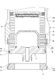
- FIG. 1 the front side in FIG. 1 will be referred to as the front side (front side) of the accumulator, and the description will be made with reference to the vertical and horizontal directions when viewed from the front side.
- the accumulator 1 is a metal bellows type accumulator that uses a metal bellows as the bellows body 31 and is used as a pressure accumulator, a pulsation damping device, or the like in an automotive hydraulic system, an industrial hydraulic system, or the like.
- the accumulator 1 is mainly composed of a housing 2 and a bellows 3 provided in the housing 2.
- FIG. 1 shows a state in which a bellows body 31 to be described later is extended by a pressure such as liquid storage.
- the bellows 3 is mainly composed of a metal bellows body 31 having a substantially cylindrical shape whose upper and lower ends are open, and a metal bellows cap 32 having a disk shape. ing.
- the bellows main body 31 has an outer diameter D1 smaller than an inner diameter d2 of an upper end side of a cylindrical portion 42 of the shell 4 and an inner diameter d4 of the opening 4a of the shell 4 (D1 ⁇ d2, d4: (See FIG. 1).
- the bellows body 31 is welded and fixed to the inner surface of an oil port member 5 (base body) described later (specifically, the welded portion 54a of the second annular convex portion 54), and the fixed end 31a (one end) constituting the lower end is closed.
- the lower surface 32a of the bellows cap 32 is welded and fixed while the annular protective ring 33 is sandwiched, and the floating end 31b constituting the upper end is closed.
- the protective ring 33 protects the bellows main body 31 from directly contacting the inner peripheral surface 42 a on the upper end side of the cylindrical portion 42 of the shell 4, and also the outer peripheral surface 33 a of the protective ring 33 and the cylindrical portion of the shell 4.
- the inner peripheral surface 42a of 42 is slightly spaced in the radial direction so that it can slide smoothly without obstructing the expansion and contraction operation of the bellows 3.
- a bellows cap 32 has a lower surface 32a fitted with a circular seal holder 34 having a crank shape in cross section.
- a disc-like seal member 35 is attached to and fixed to the seal holder 34. .
- the seal member 35 is configured by adhering (vulcanizing and adhering) a rubber-like elastic body 37 to a part or all of the surface of a base material 36 made of metal and having a disk shape.
- the housing 2 includes a bottomed cylindrical shell 4 having an opening 4 a at the lower end, and an oil port member 5 that seals the opening 4 a of the shell 4. Yes.
- the oil port member 5 is fixed to the shell 4 by a separate fixing member 6 in a state where the opening 4a of the shell 4 is sealed.
- the shell 4 is provided with a gas filling port 40 for injecting a high-pressure gas (for example, nitrogen gas) into a gas chamber 7 (described later) formed in the housing 2 at a position substantially in the center in the radial direction of the upper end portion.
- a gas filling port 40 for injecting a high-pressure gas (for example, nitrogen gas) into a gas chamber 7 (described later) formed in the housing 2 at a position substantially in the center in the radial direction of the upper end portion.
- the gas filling port 40 is closed by screwing the gas plug 41 after the high-pressure gas is injected.
- the O-ring 41 a made of a rubber-like elastic body is interposed between the gas plug 41 and the shell 4, whereby leakage of high-pressure gas in the gas chamber 7 of the housing 2 can be prevented.
- the cylindrical portion 42 of the shell 4 is configured such that the opening 4a side is thicker toward the outer diameter side, and the inner peripheral surface 43a on the opening 4a side is closer to the inner peripheral surface 42a on the upper end side of the cylindrical portion 42.
- a first annular recess 43 to which the oil port member 5 is attached is formed, and the fixing member 6 is attached to the inner peripheral surface 44a on the opening 4a side further than the first annular recess 43 (inner peripheral surface 43a).
- a second annular recess 44 is formed.
- the first annular recess 43 has an inner diameter d3 larger than the inner diameter d2 of the inner peripheral surface 42a on the upper end side of the cylindrical portion 42 of the shell 4 (the portion on which the outer peripheral surface 33a of the protective ring 33 of the bellows 3 slides). (D2 ⁇ d3: see FIG. 1). According to this, there is a cylindrical portion between the end on the opening 4a side of the inner peripheral surface 42a of the cylindrical portion 42 of the shell 4 and the end on the upper end side of the first annular recess 43 (inner peripheral surface 43a).
- a formed first annular step 45 (regulation step) is formed.
- the second annular recess 44 has an inner diameter d4 larger than the inner diameter d3 of the first annular recess 43 (d3 ⁇ d4: see FIG. 1).
- the inner diameter d4 of the second annular recess 44 is configured to have substantially the same dimension as the inner diameter d4 of the opening 4a of the shell 4. According to this, the end on the opening 4a side of the first annular recess 43 (inner peripheral surface 43a) of the cylindrical portion 42 of the shell 4 and the end on the upper end side of the second annular recess 44 (inner peripheral surface 44a).
- annular surface portion is formed in the radial direction due to a dimensional difference between the inner diameter d3 of the first annular recess 43 and the inner diameter d4 of the second annular recess 44, and a step shape substantially perpendicular to the cylindrical portion 42 of the shell 4 is formed.
- a second annular step 46 is formed.
- the second annular recess 44 is formed with a female screw portion 44b into which a male screw portion 61b formed on the fixing member 6 described later is screwed.
- the oil port member 5 is provided with a fluid inlet / outlet passage 50 (through hole) for penetrating in the axial direction (vertical direction) and for flowing a liquid (for example, hydraulic oil) from a pressure pipe (not shown) into the housing 2. ing.
- the oil port member 5 is provided with an annular mounting portion 51 having an inner diameter d3 of the first annular recess 43 formed in the cylindrical portion 42 of the shell 4 and an outer diameter D3 thereof having substantially the same dimensions.
- An O-ring 52 annular seal member made of a rubber-like elastic body is attached to an annular groove 51b formed on the outer peripheral surface 51a of the mounting portion 51 and recessed toward the inner diameter side.
- the mounting portion 51 is configured such that the outer diameter D3 is larger than the outer diameter D1 of the bellows body 31 (D1 ⁇ D3: see FIG. 1).
- the inner surface (upper surface) of the oil port member 5 protrudes upward from the mounting portion 51 (inside the housing 2), and the inner diameter d2 of the inner peripheral surface 42a on the upper end side of the cylindrical portion 42 of the shell 4 and its A first annular convex portion 53 configured to have substantially the same outer diameter D2 is formed.
- a second annular convex portion 54 protruding upward is formed on the inner diameter side of the first annular convex portion 53.
- the fixed end 31a of the bellows main body 31 is fixed by welding.
- a third annular convex portion 55 projecting upward is formed on the inner diameter side of the second annular convex portion 54, and a substantially U-shaped stay 56 facing downward in a sectional view is welded and fixed to the outer diameter side. .
- the stay 56 is provided with a through-hole 56a penetrating in the axial direction at a position substantially in the radial direction of the upper end portion, and an annular seal surface 56b is formed on the outer diameter side of the through-hole 56a.
- the internal space of the housing 2 is a structure in which the gas chamber 7 communicating with the gas filling port 40 and the liquid chamber 8 communicating with the fluid inlet / outlet path 50 are hermetically sealed by the bellows 3 (the bellows body 31 and the bellows cap 32). It has become.
- the gas chamber 7 is defined by the inner peripheral surface 42 a of the shell 4, the outer peripheral surface 31 c of the bellows body 31, and the upper surface 32 b of the bellows cap 32, and high-pressure gas injected from the gas sealing port 40 is sealed therein.
- the liquid chamber 8 is defined by the stay 56, the inner peripheral surface 31d of the bellows main body 31, and the lower surface 32a (seal holder 34, seal member 35) of the bellows cap 32, and the liquid flows out from the pressure pipe through the fluid inlet / outlet passage 50. It comes to enter.
- the accumulator 1 adjusts the pressure by moving the bellows cap 32 to a predetermined position by balancing and expanding the bellows 3 provided in the housing 2 to balance the gas pressure in the gas chamber 7 and the liquid pressure in the liquid chamber 8. Yes.
- the bellows cap 32 receives the gas pressure in the gas chamber 7 and moves downward, and the bellows main body 31 contracts, thereby the bellows cap 32.
- the seal member 35 attached to the lower surface 32a of the plate 56 and the seal surface 56b of the stay 56 are in close contact with each other to form an annular seal portion S1 (see FIG. 2), and the through hole 56a of the stay 56 is closed.
- the fixing member 6 is formed in an annular shape by providing a through hole 60 penetrating in the axial direction on the inner diameter side, and is formed in the cylindrical portion 42 of the shell 4.
- a male screw portion 61b is formed on the outer peripheral surface 61a of the mounting portion 61 having the inner diameter d4 of the recess 44 and the outer diameter D4 of which are approximately the same size.
- the outer diameter at the apex of the crest of the male thread 61b formed on the fixing member 6 is at the bottom of the valley of the female thread 44b of the second annular recess 44 formed on the cylindrical part 42 of the shell 4. It is configured to have substantially the same dimensions as the inner diameter.
- the upper surface of the fixing member 6 protrudes upward (from the oil port member 5 side) from the mounting portion 61 and has an inner diameter d3 and an outer diameter D3 of the first annular recess 43 formed in the cylindrical portion 42 of the shell 4. Are formed with substantially the same dimensions.
- the oil port member 5 to which the fixed end 31 a of the bellows main body 31 is fixed by welding is inserted from the opening 4 a of the shell 4 so that the bellows main body 31 is disposed inside the shell 4. .
- the inner surface (upper surface) of the mounting portion 51 of the oil port member 5 is brought into contact with the first annular step portion 45 formed in the cylindrical portion 42 of the shell 4 to be fitted into the first annular recess 43.
- the oil port member 5 is positioned in the axial direction with respect to the shell 4.
- an annular seal portion S2 is formed by the O-ring 52 being interposed between the outer peripheral surface 51a of the mounting portion 51 of the oil port member 5 and the first annular recess 43 (see FIGS. 1 and 2). .
- the male screw portion 61 b formed on the outer peripheral surface 61 a of the mounting portion 61 of the fixing member 6 is screwed into the female screw portion 44 b of the second annular recess 44 formed in the cylindrical portion 42 of the shell 4.
- the annular convex portion 62 of the fixing member 6 presses the mounting portion 51 of the oil port member 5 from the outer surface side (lower surface side), so that the outer peripheral portion of the mounting portion 51 of the oil port member 5 is the first of the shell 4. It can be fixed so as to be sandwiched between the annular step 45 and the annular projection 62 of the fixing member 6.
- the oil port member 5 is restricted from moving in the axial direction with respect to the shell 4 by the first annular step 45, the oil port member can be attached by attaching the fixing member 6 to the shell 4 (second annular recess 44). 5 is fixed at a predetermined position with respect to the shell 4.
- the outer diameter D1 of the bellows body 31 is smaller than the inner diameter d4 of the opening 4a of the shell 4 (D1 ⁇ d4: see FIG. 1), and the outer diameter D3 of the mounting portion 51 of the oil port member 5 is the bellows. Since the outer diameter D1 of the main body 31 is larger (D1 ⁇ D3: see FIG. 1), the bellows main body 31 welded and fixed to the oil port member 5 is inserted from the opening 4a of the shell 4 to fix the fixing member. 6, the oil port member 5 is detachably fixed to the shell 4, so that the bellows body 31 and the oil port member 5 can be attached to the shell 4, and the bellows body 31 and the oil from the opening 4 a of the shell 4.
- An annular seal portion S2 is formed by an O-ring 52 interposed between the outer peripheral surface 51a of the mounting portion 51 of the oil port member 5 and the first annular recess 43 of the shell 4, and the inside of the liquid chamber 8 of the housing 2 is formed. Liquid leakage can be prevented.
- the welded portion between the shell 4 and the oil port member 5 extends in the circumferential direction. It needs to be welded accurately. In this case, since the shell 4 and the oil port member 5 are in a welded state, they cannot be disassembled, and it is difficult to perform maintenance work such as replacement of the bellows body 31.
- annular seal portion S2 is formed by an O-ring 52 interposed between the outer peripheral surface 51a of the mounting portion 51 of the oil port member 5 and the first annular recess 43 of the shell 4. Since leakage of the liquid in the liquid chamber 8 of the housing 2 can be prevented, the sealing performance of the housing 2 can be improved without welding the shell 4 and the oil port member 5. Further, as described above, by opening the male screw portion 61b of the attachment portion 61 of the fixing member 6 to the female screw portion 44b of the second annular recess 44 of the shell 4, the opening portion 4a of the shell 4 is oiled.
- the oil port member 5 can be fixed to the shell 4 by the separate fixing member 6 that can hold the sealed state by the port member 5 and can be easily attached to and detached from the shell 4.
- the operation of fixing and disassembling the oil port member 5 with respect to 4 can be simplified, and the maintainability of the bellows body 31 can be improved.
- the oil port member 5 is fixed to the shell 4 by screw fixing of the fixing member 6 which is separate from the oil port member 5, the oil port member 5 is fixed when the fixing member 6 is fixed to the shell 4. Since it does not rotate together with the member 6, it is possible to prevent wear caused by rubbing the O-ring 52 between the outer peripheral surface 51 a of the mounting portion 51 of the oil port member 5 and the first annular recess 43 of the shell 4. .
- the oil port member 5 to which the bellows body 31 is fixed by welding is fixed to the shell 4 by screwing, not by welding. Therefore, the oil port member 5 is not deformed by heat when being fixed to the shell 4, and Residual stress generated in the oil port member 5 after fixing can be reduced.
- the gas plug 41 of the gas filling port 40 of the shell 4 is loosened to discharge the high-pressure gas in the gas chamber 7 and gas.
- the stress from the high-pressure gas does not act on the bellows body 31 and can be removed safely.
- the gas filling port 40 can seal the high-pressure gas injected into the gas chamber 7 by screwing the gas plug 41 again, the maintainability of the accumulator 1 can be improved.
- the oil port member 5 can be easily positioned with respect to the shell 4.
- the outer peripheral portion of the mounting portion 51 of the oil port member 5 is located between the first annular step 45 of the shell 4 and the annular convex portion 62 of the fixing member 6. Therefore, the oil port member 5 can be prevented from rotating relative to the shell 4. Furthermore, by fixing the fixing member 6 to the shell 4 with a screw, a stress that presses the outer peripheral portion of the mounting portion 51 of the oil port member 5 in the axial direction (on the first annular step portion 45 side) can be applied. Therefore, the oil port member 5 can be prevented from rotating with respect to the shell 4 when the accumulator 1 is used.
- the fixing member 6 is formed in an annular shape, the fixing member 6 is fixed to the shell 4 with a screw, thereby applying a stress that presses the outer peripheral portion of the mounting portion 51 of the oil port member 5 in the axial direction. It can work evenly. Moreover, it can be made lighter than a disk-shaped configuration.
- a second annular step 46 is formed between the first annular recess 43 and the second annular recess 44 on the inner peripheral surface 42 a of the cylindrical portion 42 of the shell 4, whereby the inner diameter of the first annular recess 43 is formed. Since the axial position of the annular convex portion 62 of the fixing member 6 having d3 and its outer diameter D3 having substantially the same dimensions is not restricted, the axial position of the oil port member 5 with respect to the shell 4 is set to an appropriate position. And can be fixed securely.
- the male screw portion 61 b formed on the outer peripheral surface 61 a of the mounting portion 61 of the fixing member 6 is made to have a female screw portion 44 b formed in the second annular recess 44 of the inner peripheral surface 42 a of the cylindrical portion 42 of the shell 4. Since the fixing member 6 can be arranged on the inner diameter side of the shell 4 by screwing, the structure for fixing the oil port member 5 to the shell 4 can be made compact.
- the oil port member 5 is configured so as to be key-fitted to the shell 4 (for example, the first annular step 45 of the shell 4 is provided with a recess that is a key groove extending in the axial direction, and the outer periphery of the oil port member 5 In this case, the relative rotation of the oil port member 5 with respect to the shell 4 is restricted by the key fitting, so that the protrusion with respect to the shell 4 is restricted.
- the fixing member 6 is fixed with the screw, the oil port member 5 rotates together, so that the O-ring 52 can be prevented from rotating and the sealing performance can be ensured.
- the accumulator 101 has a male screw portion 142 c formed on the opening 104 a side of the outer peripheral surface 142 b of the cylindrical portion 142 of the shell 104.
- An O-ring 147 made of a rubber-like elastic body is attached to an annular groove 142d formed on the outer peripheral surface 142b of the cylindrical portion 142 of the shell 104 and recessed toward the inner diameter side.
- the oil port member 105 is provided with a fluid inlet / outlet passage 150 penetrating in the axial direction.
- the accumulator 101 detachably connects the accumulator 101 to the housing by screwing the male screw portion 142c of the shell 104 into a female screw portion formed in a housing provided with a pressure pipe (not shown). be able to. Further, by interposing the O-ring 147 between the casing and the outer peripheral surface 142b of the cylindrical portion 142 of the shell 104, the accumulator 101 can be hermetically connected to the casing. Further, in a state where the accumulator 101 is hermetically connected to the housing, the liquid in the pressure pipe flows into and out of the housing 2 through the through hole 60 of the fixing member 6 and the fluid inlet / outlet path 150 of the oil port member 105. be able to.
- the accumulator 201 is provided with an annular convex portion 261 that protrudes from the outer surface side (lower surface side) of the mounting portion 251 of the oil port member 205 to the opening 204 a side of the shell 204.
- the annular convex portion 261 is configured so that the inner diameter and the outer diameter of the second annular concave portion 244 formed in the cylindrical portion 242 of the shell 204 are substantially the same, and a male screw portion 261b is formed on the outer peripheral surface 261a. . That is, the oil port member 5 and the fixing member 6 of Example 1 described above are integrally configured.
- the accumulator 201 is formed by screwing the male screw portion 261b formed in the annular convex portion 261 of the oil port member 205 with the female screw portion 244a formed in the second annular concave portion 244 of the shell 204. Since the opening 204a of 204 can be kept sealed by the oil port member 205, it is not necessary to separately prepare a fixing member for fixing the oil port member 205 to the shell 204. The fixing and disassembling work of the oil port member 205 is simplified, and the maintainability of the bellows body 31 can be improved.
- a female screw portion 342c is formed on the opening 304a side of the outer peripheral surface 342b of the cylindrical portion 342 of the shell 304.
- the fixing member 306 has a cup shape that opens upward by extending the attachment portion 361 so as to cover the opening 304a side of the shell 304 from the outer diameter side, and a through hole 360 that penetrates in the axial direction to the inner diameter side. Is provided to form an annular shape. Further, the mounting portion 361 is configured so that the outer diameter and the inner diameter of the female screw portion 342c formed on the outer peripheral surface 342b of the cylindrical portion 342 of the shell 304 have substantially the same dimensions, and the inner peripheral surface 361a of the mounting portion 361 includes A male screw portion 361b is formed.
- the upper surface of the fixing member 306 protrudes upward (from the oil port member 5 side) from the mounting portion 361, and the inner diameter and outer diameter of the first annular recess 343 formed in the cylindrical portion 342 of the shell 304 are approximately the same.
- An annular convex portion 362 having the same dimensions is formed.
- the accumulator 301 is threadedly engaged with a male screw portion 361b formed on the inner peripheral surface 361a of the attachment portion 361 of the fixing member 306 to a female screw portion 342c formed on the outer peripheral surface 342b of the cylindrical portion 342 of the shell 304.
- the state in which the opening 304a of the shell 304 is sealed by the oil port member 5 can be maintained, and the oil port member 5 can be held by a separate fixing member 306 that can be easily attached to and detached from the shell 304. Since the oil port member 5 can be fixed to the shell 304, the fixing and disassembling work of the oil port member 5 with respect to the shell 304 is simplified, and the maintainability of the bellows body 31 can be improved.
- the oil port member 5 can be fixed by being sandwiched between the first annular step portion 345 of the shell 304 and the annular convex portion 362 of the fixing member 306, On the other hand, the oil port member 5 can be fixed at a predetermined position, and the oil port member 5 can be prevented from rotating with respect to the shell 304.
- annular groove 444 a that is recessed toward the outer diameter side is formed in the second annular recess 444 of the cylindrical portion 442 of the shell 404.
- the oil port member 405 is provided with a protruding portion 461 that protrudes from the outer surface side (lower surface side) of the mounting portion 451 toward the opening 404 a side of the shell 404.
- the protruding portion 461 is configured so that the inner diameter and the outer diameter of the second annular recess 444 formed in the cylindrical portion 442 of the shell 404 are substantially the same size, and the inner surface (upper surface) is formed in the cylindrical portion 442 of the shell 404.
- the second annular step 446 is configured to be fitted into the second annular recess 444 in a state where the second annular step 446 is in contact with the second annular step 446.
- the fixing member 406 has a substantially C-shaped retaining ring shape, and has an outer diameter larger than the inner diameter of the second annular recess 444 formed in the shell 404 and is formed in the second annular recess 444 of the shell 404.
- the inner diameter of the groove portion 444a and the outer diameter thereof are configured to have substantially the same dimensions.
- the fixing member 406 is not limited to a substantially C shape as long as it has a retaining ring shape.
- the accumulator 401 fits the retaining ring-shaped fixing member 406 into the groove 444 a formed in the second annular recess 444 of the shell 404, so that the opening 404 a of the shell 404 is sealed by the oil port member 405.
- the oil port member 405 can be fixed to the shell 404 by a separate fixing member 406 that can be held in a fixed state and can be easily attached to and detached from the shell 404.
- the fixing / disassembling work of the member 405 is simplified, and the maintainability of the bellows main body 31 can be improved.
- the oil port member 405 can be fixed by being sandwiched between the second annular step portion 446 of the shell 404 and the fixing member 406, the oil port member is fixed to the shell 404. While fixing 405 at a predetermined position, the oil port member 405 can be prevented from rotating with respect to the shell 404.
- the accumulators 1, 101, 201, 301, 401 are so-called external gas type accumulators in which the gas chamber 7 is set outside the bellows 3 and the liquid chamber 8 is set inside the bellows 3.
- the present invention is not limited thereto, and for example, an internal gas type accumulator (see FIG. 8) may be used in which the liquid chamber 8 is set outside the bellows 3 and the gas chamber 7 is set inside the bellows.
- the housing 2 fixes the opening part 4a, 104a, 204a, 304a, 404a of the bottomed cylindrical shell 4,104,204,304,404 by the fixing member 6,306,406.
- the oil port members 5, 105, 405 or the fixing member is described as being sealed by the oil port member 205 integrally formed, the housing is not limited to this, and the upper and lower ends of the cylindrical shell that is open at both ends are used. These openings may be sealed by an oil port member and a gas sealing member fixed by a fixing means.
- the O-ring 52 is mounted on the groove 51b formed in the oil port members 5, 105, 205, and 405.
- An O-ring may be attached to the.
- the O-ring is not limited to the one interposed between the outer peripheral surface of the mounting portion of the oil port member and the first annular concave portion of the shell, but can seal the sealing performance between the shell and the oil port member. May be arranged freely.
- an O-ring may be attached to the fixing member.
- annular seal member is not limited to the O-ring and may be other seal members such as packing.
Landscapes
- Engineering & Computer Science (AREA)
- Physics & Mathematics (AREA)
- Fluid Mechanics (AREA)
- Mechanical Engineering (AREA)
- General Engineering & Computer Science (AREA)
- Supply Devices, Intensifiers, Converters, And Telemotors (AREA)
Abstract
La présente invention concerne un accumulateur dans lequel un soufflet métallique présente une meilleure maintenabilité. Cet accumulateur (1) est pourvu d'un logement (2) ayant : une coque (4) pourvue d'une ouverture (4a) ; et un corps de base en forme de disque (5) auquel une extrémité d'un soufflet métallique (31) est soudée et fixée, le soufflet métallique (31) ayant un diamètre externe (D1) inférieur au diamètre interne (d4) de l'ouverture (4a). L'intérieur du logement (2) est divisé à l'intérieur et à l'extérieur du soufflet métallique (31) de manière étanche. Le diamètre externe (D3) du corps de base (5) est supérieur au diamètre externe (D1) du soufflet métallique (31), et le corps de base (5) est fixé de manière amovible à la coque (4).
Priority Applications (4)
| Application Number | Priority Date | Filing Date | Title |
|---|---|---|---|
| US16/605,777 US11047399B2 (en) | 2017-05-11 | 2018-04-27 | Accumulator |
| EP18799120.3A EP3623642B1 (fr) | 2017-05-11 | 2018-04-27 | Accumulateur |
| JP2019517566A JP6974449B2 (ja) | 2017-05-11 | 2018-04-27 | アキュムレータ |
| CN201880030113.2A CN110603383B (zh) | 2017-05-11 | 2018-04-27 | 蓄能器 |
Applications Claiming Priority (2)
| Application Number | Priority Date | Filing Date | Title |
|---|---|---|---|
| JP2017-094401 | 2017-05-11 | ||
| JP2017094401 | 2017-05-11 |
Publications (1)
| Publication Number | Publication Date |
|---|---|
| WO2018207654A1 true WO2018207654A1 (fr) | 2018-11-15 |
Family
ID=64105286
Family Applications (1)
| Application Number | Title | Priority Date | Filing Date |
|---|---|---|---|
| PCT/JP2018/017126 WO2018207654A1 (fr) | 2017-05-11 | 2018-04-27 | Accumulateur |
Country Status (5)
| Country | Link |
|---|---|
| US (1) | US11047399B2 (fr) |
| EP (1) | EP3623642B1 (fr) |
| JP (1) | JP6974449B2 (fr) |
| CN (1) | CN110603383B (fr) |
| WO (1) | WO2018207654A1 (fr) |
Cited By (1)
| Publication number | Priority date | Publication date | Assignee | Title |
|---|---|---|---|---|
| US11761507B2 (en) | 2021-02-10 | 2023-09-19 | DRiV Automotive Inc. | Weight optimized bellow accumulator |
Families Citing this family (1)
| Publication number | Priority date | Publication date | Assignee | Title |
|---|---|---|---|---|
| JP6702905B2 (ja) * | 2017-03-13 | 2020-06-03 | 日本発條株式会社 | アキュムレータ |
Citations (4)
| Publication number | Priority date | Publication date | Assignee | Title |
|---|---|---|---|---|
| US2561957A (en) * | 1947-10-13 | 1951-07-24 | Bendix Aviat Corp | Gas to hydraulic pressure transmitter or accumulator |
| JPS49100472A (fr) * | 1972-09-07 | 1974-09-24 | ||
| JPH0932801A (ja) * | 1995-07-19 | 1997-02-04 | Nobuyuki Sugimura | アキュムレータの隔膜支持装置 |
| JP2010174985A (ja) | 2009-01-29 | 2010-08-12 | Nhk Spring Co Ltd | アキュムレータへのガス封入方法 |
Family Cites Families (15)
| Publication number | Priority date | Publication date | Assignee | Title |
|---|---|---|---|---|
| US2365994A (en) * | 1944-03-22 | 1944-12-26 | Electrol Inc | Accumulator |
| GB1000744A (en) * | 1960-11-10 | 1965-08-11 | Plessey Co Ltd | Improvements in or relating to hydraulic accumulators |
| FR1391050A (fr) | 1964-01-17 | 1965-03-05 | Rech Etudes Production Sarl | Accumulateur hydropneumatique de sécurité, applicable notamment aux circuits hydrauliques des aérodynes |
| JPS6340641Y2 (fr) * | 1980-12-09 | 1988-10-24 | ||
| JPS5798396A (en) | 1980-12-12 | 1982-06-18 | Pilot Ink Co Ltd | Method of sealing ball pen chip |
| JP3434303B2 (ja) * | 1992-06-08 | 2003-08-04 | 日本発条株式会社 | アキュムレータ装置 |
| JP4718129B2 (ja) * | 2003-07-30 | 2011-07-06 | 日本発條株式会社 | 車両用ブレーキシステム部品 |
| DE102004004341A1 (de) | 2004-01-29 | 2005-08-18 | Hydac Technology Gmbh | Druckspeicher, insbesondere Pulsationsdämpfer |
| JP4272604B2 (ja) * | 2004-08-23 | 2009-06-03 | 日本発條株式会社 | 圧力容器及び蓄圧・緩衝装置 |
| CN100376807C (zh) * | 2006-07-12 | 2008-03-26 | 三一重工股份有限公司 | 活塞式蓄能器 |
| JP5102576B2 (ja) * | 2007-10-10 | 2012-12-19 | Nok株式会社 | アキュムレータ |
| JP5474333B2 (ja) * | 2008-11-05 | 2014-04-16 | イーグル工業株式会社 | アキュムレータ |
| JP5374435B2 (ja) | 2010-04-20 | 2013-12-25 | イーグル工業株式会社 | アキュムレータ |
| JP5872342B2 (ja) * | 2012-03-22 | 2016-03-01 | イーグル工業株式会社 | アキュムレータ |
| JP6271353B2 (ja) * | 2014-06-26 | 2018-01-31 | イーグル工業株式会社 | 電流遮断装置とそれを用いた蓄電装置 |
-
2018
- 2018-04-27 US US16/605,777 patent/US11047399B2/en active Active
- 2018-04-27 CN CN201880030113.2A patent/CN110603383B/zh active Active
- 2018-04-27 WO PCT/JP2018/017126 patent/WO2018207654A1/fr unknown
- 2018-04-27 EP EP18799120.3A patent/EP3623642B1/fr active Active
- 2018-04-27 JP JP2019517566A patent/JP6974449B2/ja active Active
Patent Citations (4)
| Publication number | Priority date | Publication date | Assignee | Title |
|---|---|---|---|---|
| US2561957A (en) * | 1947-10-13 | 1951-07-24 | Bendix Aviat Corp | Gas to hydraulic pressure transmitter or accumulator |
| JPS49100472A (fr) * | 1972-09-07 | 1974-09-24 | ||
| JPH0932801A (ja) * | 1995-07-19 | 1997-02-04 | Nobuyuki Sugimura | アキュムレータの隔膜支持装置 |
| JP2010174985A (ja) | 2009-01-29 | 2010-08-12 | Nhk Spring Co Ltd | アキュムレータへのガス封入方法 |
Non-Patent Citations (1)
| Title |
|---|
| See also references of EP3623642A4 |
Cited By (1)
| Publication number | Priority date | Publication date | Assignee | Title |
|---|---|---|---|---|
| US11761507B2 (en) | 2021-02-10 | 2023-09-19 | DRiV Automotive Inc. | Weight optimized bellow accumulator |
Also Published As
| Publication number | Publication date |
|---|---|
| US20200158144A1 (en) | 2020-05-21 |
| EP3623642A4 (fr) | 2021-02-17 |
| CN110603383B (zh) | 2021-10-22 |
| EP3623642B1 (fr) | 2024-01-10 |
| JP6974449B2 (ja) | 2021-12-01 |
| CN110603383A (zh) | 2019-12-20 |
| US11047399B2 (en) | 2021-06-29 |
| EP3623642A1 (fr) | 2020-03-18 |
| JPWO2018207654A1 (ja) | 2020-03-12 |
Similar Documents
| Publication | Publication Date | Title |
|---|---|---|
| KR101223609B1 (ko) | 유량조정장치 | |
| JP4491737B2 (ja) | 真空バルブ | |
| US4365816A (en) | Self-damping bellows seal assembly | |
| US8096324B2 (en) | Accumulator | |
| JP5997770B2 (ja) | ダブルメカニカルシール装置 | |
| NO20140893A1 (no) | Antirotasjonsmontasjer til bruk ved væskeventiler | |
| WO2018207654A1 (fr) | Accumulateur | |
| JP2011513666A (ja) | 動的封止 | |
| JP2008138696A (ja) | 油圧緩衝器の分割ピストン構造 | |
| US10330170B2 (en) | Shock absorber | |
| JP5593519B2 (ja) | シール装置用配管接続機構及びメカニカルシール装置 | |
| JP2005171985A (ja) | フラップを有するオイルフィルタガスケット | |
| JP4797090B2 (ja) | ダブルメカニカルシール | |
| US3957359A (en) | Sight glass assembly | |
| JP4956362B2 (ja) | アキュムレータ | |
| JP6991943B2 (ja) | 分割型メカニカルシール | |
| JP6458067B2 (ja) | ピストン圧縮機用弁ユニット及びピストン圧縮機 | |
| JP5531292B2 (ja) | メカニカルシール | |
| JP2016109043A (ja) | オイルフィルタのシール構造 | |
| KR101352872B1 (ko) | 어큐뮬레이터 | |
| JP2004011867A (ja) | 密封装置 | |
| JP2022111615A (ja) | ダイヤフラムバルブ | |
| JP2022039205A (ja) | 油圧機器配管ポート閉止用プラグ | |
| EP3543571A1 (fr) | Joint mécanique | |
| JP2014070688A (ja) | バルブ装置 |
Legal Events
| Date | Code | Title | Description |
|---|---|---|---|
| 121 | Ep: the epo has been informed by wipo that ep was designated in this application |
Ref document number: 18799120 Country of ref document: EP Kind code of ref document: A1 |
|
| ENP | Entry into the national phase |
Ref document number: 2019517566 Country of ref document: JP Kind code of ref document: A |
|
| NENP | Non-entry into the national phase |
Ref country code: DE |
|
| ENP | Entry into the national phase |
Ref document number: 2018799120 Country of ref document: EP Effective date: 20191211 |