WO2018207361A1 - 細胞画像取得装置 - Google Patents
細胞画像取得装置 Download PDFInfo
- Publication number
- WO2018207361A1 WO2018207361A1 PCT/JP2017/018090 JP2017018090W WO2018207361A1 WO 2018207361 A1 WO2018207361 A1 WO 2018207361A1 JP 2017018090 W JP2017018090 W JP 2017018090W WO 2018207361 A1 WO2018207361 A1 WO 2018207361A1
- Authority
- WO
- WIPO (PCT)
- Prior art keywords
- illumination
- light
- light source
- image acquisition
- acquisition device
- Prior art date
- Legal status (The legal status is an assumption and is not a legal conclusion. Google has not performed a legal analysis and makes no representation as to the accuracy of the status listed.)
- Ceased
Links
Images


Classifications
-
- G—PHYSICS
- G02—OPTICS
- G02B—OPTICAL ELEMENTS, SYSTEMS OR APPARATUS
- G02B21/00—Microscopes
- G02B21/0004—Microscopes specially adapted for specific applications
- G02B21/002—Scanning microscopes
- G02B21/0024—Confocal scanning microscopes (CSOMs) or confocal "macroscopes"; Accessories which are not restricted to use with CSOMs, e.g. sample holders
- G02B21/008—Details of detection or image processing, including general computer control
-
- G—PHYSICS
- G02—OPTICS
- G02B—OPTICAL ELEMENTS, SYSTEMS OR APPARATUS
- G02B21/00—Microscopes
- G02B21/06—Means for illuminating specimens
- G02B21/08—Condensers
- G02B21/082—Condensers for incident illumination only
-
- C—CHEMISTRY; METALLURGY
- C12—BIOCHEMISTRY; BEER; SPIRITS; WINE; VINEGAR; MICROBIOLOGY; ENZYMOLOGY; MUTATION OR GENETIC ENGINEERING
- C12M—APPARATUS FOR ENZYMOLOGY OR MICROBIOLOGY; APPARATUS FOR CULTURING MICROORGANISMS FOR PRODUCING BIOMASS, FOR GROWING CELLS OR FOR OBTAINING FERMENTATION OR METABOLIC PRODUCTS, i.e. BIOREACTORS OR FERMENTERS
- C12M1/00—Apparatus for enzymology or microbiology
-
- G—PHYSICS
- G02—OPTICS
- G02B—OPTICAL ELEMENTS, SYSTEMS OR APPARATUS
- G02B21/00—Microscopes
- G02B21/24—Base structure
- G02B21/26—Stages; Adjusting means therefor
-
- G—PHYSICS
- G02—OPTICS
- G02B—OPTICAL ELEMENTS, SYSTEMS OR APPARATUS
- G02B21/00—Microscopes
- G02B21/36—Microscopes arranged for photographic purposes or projection purposes or digital imaging or video purposes including associated control and data processing arrangements
-
- G—PHYSICS
- G02—OPTICS
- G02B—OPTICAL ELEMENTS, SYSTEMS OR APPARATUS
- G02B21/00—Microscopes
- G02B21/36—Microscopes arranged for photographic purposes or projection purposes or digital imaging or video purposes including associated control and data processing arrangements
- G02B21/361—Optical details, e.g. image relay to the camera or image sensor
-
- G—PHYSICS
- G02—OPTICS
- G02B—OPTICAL ELEMENTS, SYSTEMS OR APPARATUS
- G02B21/00—Microscopes
- G02B21/36—Microscopes arranged for photographic purposes or projection purposes or digital imaging or video purposes including associated control and data processing arrangements
- G02B21/362—Mechanical details, e.g. mountings for the camera or image sensor, housings
-
- H—ELECTRICITY
- H04—ELECTRIC COMMUNICATION TECHNIQUE
- H04N—PICTORIAL COMMUNICATION, e.g. TELEVISION
- H04N23/00—Cameras or camera modules comprising electronic image sensors; Control thereof
- H04N23/56—Cameras or camera modules comprising electronic image sensors; Control thereof provided with illuminating means
-
- H—ELECTRICITY
- H04—ELECTRIC COMMUNICATION TECHNIQUE
- H04N—PICTORIAL COMMUNICATION, e.g. TELEVISION
- H04N23/00—Cameras or camera modules comprising electronic image sensors; Control thereof
- H04N23/50—Constructional details
Definitions
- the present invention relates to a cell image acquisition device.
- a cell analysis method for analyzing the state of a cell from an image acquired by photographing the cell is known (for example, see Patent Document 1).
- illumination light is irradiated from above a cell culture surface for culturing cells, and a line-shaped photosensor array for detecting light transmitted through the cells is arranged below the culture surface.
- the image is acquired by sliding in one horizontal direction orthogonal to the axis.
- the illumination light irradiated from above is caused by the meniscus of the culture solution surface due to the refractive index of the culture solution or the surface tension.
- the cells are refracted unevenly and the cells may not be irradiated through a desired path. For example, if you want to acquire an image that emphasizes the outline of a cell using the difference in refractive index between the culture medium and the cell, the cell is transmitted when the refractive direction of the illumination light changes due to the curvature of the culture liquid surface.
- the effect of enhancing the contour is diminished because the difference between the light that has been transmitted and the light that has not passed through the cells is reduced.
- the present invention has been made in view of the above-described circumstances, and is a cell image acquisition device capable of irradiating cells with illumination light through a desired path even when the refractive index of the culture solution or the curvature of the culture solution surface is generated.
- the purpose is to provide.
- One embodiment of the present invention is a stage that supports a container that accommodates cells together with a culture solution, a light source that emits illumination light, and an illumination light that is disposed below the stage and that emits the illumination light emitted from the light source.
- a condensing lens that condenses the light that has passed through the container when incident from above the liquid surface, and a diaphragm that is arranged to shield part of the light collected by the condensing lens;
- An image sensor that has a plurality of pixels arranged in a straight line to capture light that has passed through the diaphragm, and the light source, the condenser lens, the diaphragm, the image sensor, and the stage are arranged in the pixel arrangement direction.
- a moving mechanism that relatively moves in a horizontal direction orthogonal to the illumination angle adjustment that adjusts an incident angle of the illumination light to the liquid surface of the culture solution around an axis parallel to the pixel arrangement direction of the image sensor Cell image comprising It is obtained apparatus.
- the illumination light enters the culture liquid from above the liquid level of the culture liquid.
- the light that has passed through the container is collected by a condenser lens, and the light that has passed through the aperture is photographed by the image sensor. Since the imaging element has a plurality of pixels arranged in a straight line, the two-dimensional surface of the bottom of the container can be moved by moving it relative to the stage in a direction perpendicular to the pixel arrangement direction by operating the moving mechanism. Images can be acquired.
- the refraction generated by passing through the cell is used to block the light that has passed through the cell by passing light that does not pass through the cell.
- the diaphragm By arranging the diaphragm so that the condition to do is satisfied, it is possible to acquire an image in which the cells are distinguished from other parts. In this case, even if the diaphragm is set at the position where the illumination light passes through the horizontal liquid level, the liquid level of the culture solution passes through a curved portion due to surface tension or the like. Does not hold the above condition because the illumination light is further refracted on the liquid surface.
- the angle of incidence of the illumination light on the liquid surface of the culture solution is adjusted around the axis parallel to the arrangement direction of the pixels of the image sensor by the operation of the illumination angle adjustment unit.
- the illumination light is irradiated to the cells in a desired path so as to satisfy the above condition, and a high-contrast image in which the cells are emphasized can be acquired.
- the illumination angle adjustment unit may adjust the incident angle according to a relative movement position by the movement mechanism.
- the said illumination angle adjustment part may change the angle of the said light source.
- deviation member which deflects the illumination light inject
- the said illumination angle adjustment part may change the angle of the said deflection
- the said light source is provided with the point light source and the condensing lens for illumination which condenses the illumination light from this point light source, and the said illumination angle adjustment part is light of the said condensing lens for illumination.
- the point light source may be moved in a direction intersecting the axis. By doing so, the angle of the light beam emitted from the condenser lens can be changed by moving the point light source with respect to the condenser lens in the direction intersecting the optical axis of the condenser lens, The incident angle of the illumination light to the liquid surface of the culture solution can be easily changed.
- the image processing device includes a contrast calculation unit that calculates a contrast value from a pixel value output from each pixel of the image sensor, and the illumination angle adjustment unit has the contrast value calculated by the contrast calculation unit. You may adjust the said incident angle so that it may become the maximum. By doing so, the incident angle is adjusted so that the contrast value is maximized at each position of the light source, the condensing lens, the diaphragm, and the relative movement between the image sensor and the stage by the moving mechanism, and the entire structure has a high contrast. Images can be acquired.
- the average value calculation part which calculates the average value of the pixel value output from each said pixel of the said image pick-up element is provided, and the said illumination angle adjustment part calculates the said average value by the change of the said incident angle
- the incident angle may be adjusted in a range in which the average value calculated by the unit changes. In this way, even if the liquid level of the culture vessel changes, a part of the light beam that has passed through the vessel can pass through the diaphragm, and the rest can be kept shielded from light by the diaphragm, thereby making the cells stand out. High contrast images can be obtained.
- the present invention it is possible to irradiate cells with illumination light through a desired route even when the refractive index of the culture solution or the curvature of the culture solution surface is generated.
- the cell image acquisition apparatus 1 includes a stage 3 that horizontally supports a container 2 that accommodates cells X together with a culture solution Y, and is disposed below the stage 3. And a scanner 4 provided so as to be movable in the horizontal direction with respect to the stage 3.
- the stage 3 has a transparent portion capable of transmitting light at least partially.
- the scanner 4 includes a light source 5 that emits illumination light obliquely upward from below the stage 3, a condenser lens 6 that collects light emitted obliquely from above through the transparent portion of the stage 3, An image sensor 7 that detects light collected by the condenser lens 6, a diaphragm 8 that is disposed between the condenser lens 6 and the image sensor 7, the light source 5, the condenser lens 6, the diaphragm 8, and an image sensor. And a moving mechanism 9 for moving the element 7 in one horizontal direction. As shown in FIG. 2, the moving mechanism 9 includes a guide rail 10 that guides horizontal movement, a motor 11, and a ball screw 12. In the figure, reference numeral 12a denotes a screw shaft, and reference numeral 12b denotes a nut. In addition, the scanner 4 includes an illumination angle adjustment unit 13 that moves the light source 5.
- the image sensor 7 is a line sensor including a plurality of pixels arranged in a direction orthogonal to the moving direction of the moving mechanism 9 as shown in FIG.
- the condenser lens 6 is a lens array including a plurality of lenses arranged in the pixel arrangement direction corresponding to each pixel of the image sensor 7.
- the light source 5 has an elongated shape that extends in the arrangement direction of the pixels of the image sensor 7 and is disposed obliquely upward below the stage 3.
- the illumination light emitted from the light source 5 passes through the transparent portion of the stage 3, the bottom surface of the container 2, and the culture solution Y obliquely upward, and is reflected by the lower surface of the top plate 2 a of the container 2.
- the light can enter the liquid surface of the culture solution Y again from obliquely above.
- the diaphragm 8 passes through the container 2 without passing through the cell X among the illumination light incident obliquely downward from above the culture solution Y, and is collected by the condenser lens 6.
- the emitted light is allowed to pass through and passes through the cell X, so that the light condensed by the condenser lens 6 after being refracted by the cell X is disposed at a position where it is blocked.
- the diaphragm 8 when the illumination light is substantially parallel light, the diaphragm 8 is disposed in the vicinity of the focal plane of the condenser lens 6 and enters the condenser lens 6 as substantially parallel light without passing through the cell X.
- the light is allowed to pass through a through hole 8a provided at the center of the diaphragm 8, and the light refracted by the cell X is blocked by being removed from the through hole 8a.
- the illumination light usually has a certain spread angle, it is not condensed at one point even on the focal plane of the condenser lens 6 and is condensed with a certain spread. It is desirable that the diaphragm 8 be disposed at a position where about half of the light having a certain spread is blocked. As a result, the light that does not pass through the cell X (background light) has a brightness that is blocked by about half, and the light that passes through the cell X enters the condenser lens 6 at an angle different from that of the background light. It is brighter or darker than the background light.
- the illumination angle adjusting unit 13 translates the light source 5 in a direction along the moving direction by the moving mechanism 9, and about an axis orthogonal to the moving direction by the moving mechanism 9.
- a rocking mechanism 15 that rocks the light source 5 is provided.
- the illumination angle adjuster 13 is a contrast value formed by a difference between a maximum value and a minimum value of pixel values output from a plurality of pixels of the image sensor 7.
- a control unit 17 that controls the translation mechanism 14 and the swing mechanism 15 so that the contrast value calculated by the contrast calculation unit 16 is maximized.
- the control unit 17 and the contrast calculation unit 16 are configured by a processor.
- the illumination light emitted upward from the light source 5 is used to remove the transparent portion of the stage 3, the bottom surface of the container 2, and the culture solution Y.
- the light passes through and is reflected by the top plate 2a of the container 2 disposed above the culture medium Y, is incident obliquely on the liquid surface of the culture medium Y, and the culture medium Y, the bottom surface of the container 2, and the transparent portion of the stage 3
- the light source 5 is arranged at a position and an angle at which about half of the light beam transmitted through the condenser lens 6 is shielded by the diaphragm 8 and the moving mechanism 9 is operated to acquire an image. To do.
- the light passing through the cell X and the background light not passing through the cell X are incident on the condenser lens 6 at different angles, and the focal planes have different positions.
- the image of the cell X can be brightened or darkened to obtain an image that is highlighted from the background light.
- the illumination angle adjusting unit 13 is operated, and the incident position and the incident angle of the illumination light on the liquid surface of the culture medium Y are set as shown by the solid line in FIG.
- the top plate 2a of the container 2 is inclined, or the height of the liquid surface of the culture medium Y is fluctuated, while maintaining the condition that a part of the light condensed by the condenser lens 6 is removed by the diaphragm, it is possible to acquire a high-contrast image in which the cells X are distinguished from the background.
- the light source 5 is disposed below the stage 3, and illumination light is emitted obliquely upward and reflected by the top plate 2 a of the container 2. Thereby, the height dimension of the cell image acquisition apparatus 1 can be restrained low.
- the light source 5 may be disposed at a position where the container 2 is sandwiched between the stage 3 and the illumination light may be incident obliquely from above.
- the light source 5 includes a point light source 18 and a condensing lens (condensing lens for illumination) 19 that condenses light from the point light source 18, preferably a collimating lens.
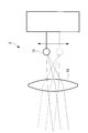
- the angle of the illumination light emitted from the condenser lens 19 may be changed by moving the point light source 18 relative to the condenser lens 19 in the horizontal direction.
- the condensing lens 19 can suppress the spread angle of the illumination light and can adjust the angle of the illumination light.
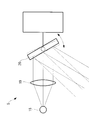
- a light source 5 that includes a point light source 18 and a mirror (deflection member) 20 that deflects light from the point light source 18 is adopted to swing the deflection member 20.
- the angle of the illumination light may be changed.
- the contrast calculation unit 16 that calculates the contrast value from the difference between the maximum value and the minimum value of the pixel values acquired by the plurality of pixels of the image sensor 7 is employed.
- An average value calculation unit that calculates an average value of pixel values acquired by a plurality of pixels of the element 7 is adopted, and the illumination angle adjustment unit 13 is operated so that the average value is arranged in a range A shown in FIG. You may decide to make it.
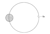
- the range A in FIG. 8 is a range in which the average value changes when the incident angle of the illumination light is changed, and as shown in FIG. 9, the light flux condensed by the condenser lens 6 ( (Indicated by hatching) indicates that the diaphragm 8 is partially cut off.
- the adjustment can be performed even in the absence of the cell X, as compared with the case where the adjustment is performed so that the contrast value is maximized.
- the incident angle of the illumination light to the culture medium Y is adjusted in real time. Instead of this, the incident angle is measured at a plurality of positions in the moving direction by the moving mechanism 9 prior to observation. It is also possible to obtain an optimum angle by changing the above and interpolate the obtained incident angles before and after the obtained angle in advance.
Landscapes
- Physics & Mathematics (AREA)
- Chemical & Material Sciences (AREA)
- General Physics & Mathematics (AREA)
- Analytical Chemistry (AREA)
- Optics & Photonics (AREA)
- Engineering & Computer Science (AREA)
- Multimedia (AREA)
- Health & Medical Sciences (AREA)
- Life Sciences & Earth Sciences (AREA)
- Bioinformatics & Cheminformatics (AREA)
- Organic Chemistry (AREA)
- Wood Science & Technology (AREA)
- Biotechnology (AREA)
- General Engineering & Computer Science (AREA)
- Zoology (AREA)
- Medicinal Chemistry (AREA)
- Sustainable Development (AREA)
- Microbiology (AREA)
- Biochemistry (AREA)
- Biomedical Technology (AREA)
- General Health & Medical Sciences (AREA)
- Genetics & Genomics (AREA)
- Signal Processing (AREA)
- Computer Vision & Pattern Recognition (AREA)
- Microscoopes, Condenser (AREA)
- Apparatus Associated With Microorganisms And Enzymes (AREA)
Abstract
培養液の屈折率や培養液面の湾曲が発生しても所望の経路で照明光を細胞に照射することを目的として、本発明に係る細胞画像取得装置(1)は、細胞(X)を培養液(Y)とともに収容する容器(2)を支持するステージ(3)と、照明光を射出する光源(5)と、ステージの下方に配置され、光源から射出された照明光を培養液の液面の上方から入射させたときに、容器を透過した光を集光する集光レンズ(6)と、集光された光の一部を遮光するように配置された絞り(8)と、絞りを通過した光を撮影する、直線状に配列された複数の画素を有する撮像素子(7)と、光源、集光レンズ、絞りおよび撮像素子とステージとを、画素の配列方向に直交する水平方向に相対的に移動させる移動機構(9)と、照明光の培養液の液面への入射角度を撮像素子の画素の配列方向に平行な軸線回りに調節する照明角度調節部とを備える。
Description
本発明は、細胞画像取得装置に関するものである。
細胞を撮影して取得された画像から細胞の状態を解析する細胞解析方法が知られている(例えば、特許文献1参照。)。特許文献1の細胞解析方法は、細胞を培養する細胞培養面の上方から照明光を照射し、細胞を透過した光を検出するライン状のフォトセンサアレイを培養面の下方においてフォトセンサアレイの長手軸に直交する水平一方向にスライドさせて画像を取得している。
しかしながら、細胞は培養容器内に貯留された培養液内において培養されているため、培養液の屈折率や表面張力による培養液面のメニスカスなどにより、上方から照射される照明光が培養液面において不均一に屈折させられてしまい、所望の経路で細胞に照射されないことがあるという不都合がある。例えば、培養液と細胞の屈折率の差を利用して細胞の輪郭を強調した画像を取得したい場合に、培養液面が湾曲していることによって照明光の屈折方向が変化すると、細胞を透過した光と細胞を透過していない光との差が小さくなって輪郭の強調効果が減殺されてしまうという不都合がある。
本発明は上述した事情に鑑みてなされたものであって、培養液の屈折率や培養液面の湾曲が発生しても所望の経路で照明光を細胞に照射することができる細胞画像取得装置を提供することを目的としている。
本発明の一態様は、細胞を培養液とともに収容する容器を支持するステージと、照明光を射出する光源と、前記ステージの下方に配置され、前記光源から射出された照明光を前記培養液の液面の上方から入射させたときに、前記容器を透過した光を集光する集光レンズと、該集光レンズにより集光された光の一部を遮光するように配置された絞りと、該絞りを通過した光を撮影する、直線状に配列された複数の画素を有する撮像素子と、前記光源、前記集光レンズ、前記絞りおよび前記撮像素子と前記ステージとを、前記画素の配列方向に直交する水平方向に相対的に移動させる移動機構と、前記照明光の前記培養液の液面への入射角度を前記撮像素子の前記画素の配列方向に平行な軸線回りに調節する照明角度調節部とを備える細胞画像取得装置である。
本態様によれば、細胞を培養液とともに収容した容器をステージに支持させて、光源から照明光を射出させると、照明光が培養液の液面の上方から培養液内に入射される。容器を透過した光は集光レンズによって集光され絞りを通過した光が撮像素子によって撮影される。撮像素子は直線状に配列された複数の画素を有するので、移動機構の作動により画素の配列方向に直交する方向にステージとの間で水平方向に相対移動させることにより、容器の底面の2次元的な画像を取得することができる。
この場合に、培養液と培養液内の細胞とは屈折率が相違するため、細胞を通過することにより発生する屈折を利用して、細胞を通過しない光を通過させ細胞を通過した光を遮断する条件が成立するように絞りを配置しておくことにより、細胞を他の部分から際立たせた画像を取得することができる。そして、この場合において、照明光が水平な液面を通過する位置で上記のような絞りの設定を行っても、培養液の液面が表面張力等によって湾曲している部分を通過する場合には、照明光が液面においてさらに屈折するために上記条件が成立しないようになる。
本態様によれば、このような場合にも、照明角度調節部の作動により、照明光の培養液の液面への入射角度を撮像素子の画素の配列方向に平行な軸線回りに調節することにより、上記条件を満たすように、すなわち、所望の経路で照明光が細胞に照射されるように調節することができ、細胞を際立たせた高コントラストの画像を取得することができる。
上記態様においては、前記照明角度調節部が、前記移動機構による相対移動位置に応じて前記入射角度を調節してもよい。
このようにすることで、移動機構により光源、集光レンズ、絞りおよび撮像素子とステージとが相対移動させられると、照明光は培養液の液面の異なる位置を通過させられることになるので、相対移動位置に応じて照明角度調節部により、液面への入射角度を調節することによって、全ての相対移動位置において上記条件が満たされた高コントラストの画像を取得することができる。
このようにすることで、移動機構により光源、集光レンズ、絞りおよび撮像素子とステージとが相対移動させられると、照明光は培養液の液面の異なる位置を通過させられることになるので、相対移動位置に応じて照明角度調節部により、液面への入射角度を調節することによって、全ての相対移動位置において上記条件が満たされた高コントラストの画像を取得することができる。
また、上記態様においては、前記照明角度調節部が、前記光源の角度を変更してもよい。
このようにすることで、光源自体の角度を変更して、培養液の液面への照明光の入射角度を容易に変更することができる。
このようにすることで、光源自体の角度を変更して、培養液の液面への照明光の入射角度を容易に変更することができる。
また、上記態様においては、前記光源から射出された照明光を偏向する偏向部材を備え、前記照明角度調節部が、前記偏向部材の角度を変更してもよい。
このようにすることで、光源を固定して偏向部材の角度を変更することにより、培養液の液面への照明光の入射角度を容易に変更することができる。
このようにすることで、光源を固定して偏向部材の角度を変更することにより、培養液の液面への照明光の入射角度を容易に変更することができる。
また、上記態様においては、前記光源が、点光源と、該点光源からの照明光を集光する照明用集光レンズとを備え、前記照明角度調節部が、前記照明用集光レンズの光軸に交差する方向に前記点光源を移動させてもよい。
このようにすることで、集光レンズに対して点光源を、集光レンズの光軸に交差する方向に移動することにより、集光レンズから射出される光束の角度を変化させることができ、培養液の液面への照明光の入射角度を容易に変更することができる。
このようにすることで、集光レンズに対して点光源を、集光レンズの光軸に交差する方向に移動することにより、集光レンズから射出される光束の角度を変化させることができ、培養液の液面への照明光の入射角度を容易に変更することができる。
また、上記態様においては、前記撮像素子の各前記画素から出力される画素値からコントラスト値を算出するコントラスト算出部を備え、前記照明角度調節部が、前記コントラスト算出部により算出されたコントラスト値が最大となるように前記入射角度を調節してもよい。
このようにすることで、移動機構による光源、集光レンズ、絞りおよび撮像素子とステージとの相対移動の各位置において、コントラスト値が最大となるように入射角度が調節され、全体にわたって高コントラストの画像を取得することができる。
このようにすることで、移動機構による光源、集光レンズ、絞りおよび撮像素子とステージとの相対移動の各位置において、コントラスト値が最大となるように入射角度が調節され、全体にわたって高コントラストの画像を取得することができる。
また、上記態様においては、前記撮像素子の各前記画素から出力される画素値の平均値を算出する平均値算出部を備え、前記照明角度調節部が、前記入射角度の変化により前記平均値算出部により算出される平均値が変化する範囲に前記入射角度を調節してもよい。
このようにすることで、培養容器の液面が変化しても、容器を通過した光束の一部分が絞りを通過し、残りが絞りによって遮光される状態に維持することができ、細胞を際立たせた高コントラストの画像を取得することができる。
このようにすることで、培養容器の液面が変化しても、容器を通過した光束の一部分が絞りを通過し、残りが絞りによって遮光される状態に維持することができ、細胞を際立たせた高コントラストの画像を取得することができる。
本発明によれば、培養液の屈折率や培養液面の湾曲が発生しても所望の経路で照明光を細胞に照射することができるという効果を奏する。
本発明の一実施形態に係る細胞画像取得装置1について図面を参照して以下に説明する。
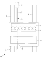
本実施形態に係る細胞画像取得装置1は、図1に示されるように、細胞Xを培養液Yとともに収容する容器2を搭載して水平に支持するステージ3と、該ステージ3の下方に配置されステージ3に対して水平方向に移動可能に設けられたスキャナ4とを備えている。
ステージ3は、少なくとも一部に光を透過可能な透明部分を有している。
本実施形態に係る細胞画像取得装置1は、図1に示されるように、細胞Xを培養液Yとともに収容する容器2を搭載して水平に支持するステージ3と、該ステージ3の下方に配置されステージ3に対して水平方向に移動可能に設けられたスキャナ4とを備えている。
ステージ3は、少なくとも一部に光を透過可能な透明部分を有している。
スキャナ4は、ステージ3の下方から斜め上方に向けて照明光を射出する光源5と、ステージ3の透明部分を介して斜め上方から射出されてくる光を集光する集光レンズ6と、該集光レンズ6により集光された光を検出する撮像素子7と、集光レンズ6と撮像素子7との間に配置された絞り8と、これら光源5、集光レンズ6、絞り8および撮像素子7を水平方向一方向に移動させる移動機構9とを備えている。移動機構9は、図2に示されるように、水平方向の移動を案内するガイドレール10と、モータ11およびボールネジ12とを備えている。図中、符号12aはねじ軸、符号12bはナットを示す。
また、スキャナ4は、光源5を移動させる照明角度調節部13を備えている。
また、スキャナ4は、光源5を移動させる照明角度調節部13を備えている。
撮像素子7は、図2に示されるように、移動機構9による移動方向に直交する方向に配列された複数の画素を備えるラインセンサである。集光レンズ6は、撮像素子7の各画素に対応して、画素の配列方向に配列された複数のレンズを備えるレンズアレイである。
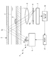
光源5は、図2に示されるように、撮像素子7の画素の配列方向に延びて配置される細長い形状を有し、ステージ3の下方に斜め上向きに配置されている。図3に示されるように、光源5から射出された照明光は、斜め上向きに、ステージ3の透明部分、容器2の底面および培養液Yを透過し、容器2の天板2aの下面によって反射されて、斜め上方から培養液Yの液面に再度入射させられるようになっている。
絞り8は、図3に示されるように、培養液Yの上方から斜め下方に向かって入射された照明光の内、細胞Xを通過することなく容器2を透過し、集光レンズ6によって集光された光については通過させ、細胞Xを通過することにより、細胞Xによって屈折された後に集光レンズ6によって集光された光については遮断する位置に配置されている。
例えば、照明光が略平行光である場合には、絞り8は集光レンズ6の焦点面近傍に配置されており、細胞Xを通過することなく略平行光のまま集光レンズ6に入射した光については絞り8の中央に備えられた透孔8aを通過させ、細胞Xによって屈折された光については、透孔8aから外れることで遮断されるようになっている。
照明光は、通常、ある程度の広がり角を有するので、集光レンズ6の焦点面でも1点に集光することはなく、一定の広がりをもって集光する。絞り8は一定の広がりを持つ光を約半分ほど遮光する位置に配置されることが望ましい。これにより、細胞Xを通過しない光(背景光)は半分ほど遮光された明るさとなり、細胞Xを通過した光は背景光とは異なる角度で集光レンズ6に入射するため、その角度により、背景光より明るくまたは暗くなるようになっている。
照明角度調節部13は、図3および図4に示す例では、光源5を移動機構9による移動方向に沿う方向に並進移動させる並進機構14と、移動機構9による移動方向に直交する軸線回りに光源5を揺動させる揺動機構15とを備えている。これにより、照明角度調節部13を作動させると、並進機構14による光源5の並進移動と、揺動機構15による光源5の揺動との組合せにより、照明光の照明角度が調節されるようになっている。
さらに具体的には、照明角度調節部13は、図3および図4に示されるように、撮像素子7の複数の画素から出力される画素値の最大値と最小値との差分からなるコントラスト値を算出するコントラスト算出部16と、該コントラスト算出部16により算出されたコントラスト値が最も大きくなるように並進機構14および揺動機構15を制御する制御部17とを備えている。制御部17およびコントラスト算出部16はプロセッサにより構成されている。
このように構成された本実施形態に係る細胞画像取得装置1の作用について以下に説明する。
本実施形態に係る細胞画像取得装置1を用いて細胞Xの画像を取得するには、光源5から上向きに射出された照明光が、ステージ3の透明部分、容器2の底面および培養液Yを透過して培養液Yの上方に配置されている容器2の天板2aにより反射され、培養液Yの液面に斜め上方から入射され、培養液Y、容器2の底面およびステージ3の透明部分を透過して集光レンズ6により集光された光束の半分ほどが絞り8により遮光される位置および角度に光源5を配置して、移動機構9を作動させることにより撮像素子7により画像を取得する。
本実施形態に係る細胞画像取得装置1を用いて細胞Xの画像を取得するには、光源5から上向きに射出された照明光が、ステージ3の透明部分、容器2の底面および培養液Yを透過して培養液Yの上方に配置されている容器2の天板2aにより反射され、培養液Yの液面に斜め上方から入射され、培養液Y、容器2の底面およびステージ3の透明部分を透過して集光レンズ6により集光された光束の半分ほどが絞り8により遮光される位置および角度に光源5を配置して、移動機構9を作動させることにより撮像素子7により画像を取得する。
上述したように、細胞Xと培養液Yとの屈折率差により、細胞Xを通過する光と細胞Xを通過しない背景光とが異なる角度で集光レンズ6に入射され、焦点面の異なる位置に集光されることを利用して、細胞Xの画像を明るくまたは暗くすることにより背景光から際立たせた画像を取得することができる。
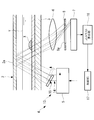
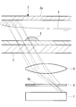
この場合において、図5に示されるように、培養液Yの液面に表面張力等によってメニスカスが発生したり、容器2の天板2aが傾斜したり、培養液Yの液面の高さが変動したりすることにより、照明光の入射角度を一定に保ったまま撮影したのでは、図5に鎖線で示されるように、集光レンズ6への光の入射角度が変化して、絞り8によりけられていた細胞Xを通過した光が透孔8aを通過してしまい、細胞Xのコントラストが低下することが発生する。あるいは、集光レンズ6への光の入射角度が変化する結果、背景光が絞り8によってけられると背景が暗くなって視認性が低下することがある。
本実施形態によれば、このような場合に、照明角度調節部13を作動させて、図5に実線で示されるように、培養液Yの液面への照明光の入射位置および入射角度を調節することにより、培養液Yの液面に表面張力等によってメニスカスが発生したり、容器2の天板2aが傾斜したり、培養液Yの液面の高さが変動したりしても、集光レンズ6により集光された光の一部が絞りによりけられる条件を維持して、細胞Xを背景から際立たせたコントラストの高い画像を取得することができる。
なお、本実施形態においては、光源5をステージ3の下方に配置し、斜め上方に照明光を射出して容器2の天板2aによって反射させることとした。これにより、細胞画像取得装置1の高さ寸法を低く抑えることができる。これに代えて、ステージ3の上方にスペースがある場合には、ステージ3との間に容器2を挟む位置に光源5を配置し、斜め上方から照明光を入射させることにしてもよい。
また、図6に示されるように、光源5として、点光源18と、該点光源18からの光を集光する集光レンズ(照明用集光レンズ)19、好ましくは、コリメートレンズとを備えるものを採用し、集光レンズ19に対して点光源18を水平方向に相対移動させることにより、集光レンズ19から射出される照明光の角度を変更することにしてもよい。集光レンズ19により、照明光の広がり角度を抑制することができるとともに、照明光の角度を調整することができる。
また、図7に示されるように、光源5として、点光源18と該点光源18からの光を偏向するミラー(偏向部材)20とを備えるものを採用し、偏向部材20を揺動させることにより、照明光の角度を変更することにしてもよい。
また、本実施形態においては、撮像素子7の複数画素により取得された画素値の最大値と最小値との差分からコントラスト値を算出するコントラスト算出部16を採用したが、これに代えて、撮像素子7の複数画素により取得された画素値の平均値を算出する平均値算出部を採用し、該平均値が図8に示される範囲Aに配置されるように、照明角度調節部13を作動させることにしてもよい。
すなわち、図8の範囲Aは、照明光の入射角度を変化させたときに平均値が変化する範囲であり、図9に示すように、集光レンズ6によって集光された光束(図中、ハッチングで示す。)が絞り8によって部分的にけられている状態にあることを示している。これにより、細胞Xを背景から際立たせたコントラストの高い画像を取得することができる。また、この方法によれば、コントラスト値が最大となるように調整する場合と比較して、細胞Xが存在しない状態でも調整することができるという利点がある。
また、本実施形態においては、培養液Yへの照明光の入射角度をリアルタイムに調節することとしたが、これに代えて、観察に先立ち、移動機構9による移動方向の複数の位置において入射角度を変更して最適な角度を求めておき、間の位置においては、求められた前後の入射角度を補間して入射角度を予め決定しておくことにしてもよい。
1 細胞画像取得装置
2 容器
3 ステージ
5 光源
6 集光レンズ
7 撮像素子
8 絞り
9 移動機構
13 照明角度調節部
16 コントラスト算出部
18 点光源
19 集光レンズ(照明用集光レンズ)
20 ミラー(偏向部材)
X 細胞
Y 培養液
2 容器
3 ステージ
5 光源
6 集光レンズ
7 撮像素子
8 絞り
9 移動機構
13 照明角度調節部
16 コントラスト算出部
18 点光源
19 集光レンズ(照明用集光レンズ)
20 ミラー(偏向部材)
X 細胞
Y 培養液
Claims (7)
- 細胞を培養液とともに収容する容器を支持するステージと、
照明光を射出する光源と、
前記ステージの下方に配置され、前記光源から射出された照明光を前記培養液の液面の上方から入射させたときに、前記容器を透過した光を集光する集光レンズと、
該集光レンズにより集光された光の一部を遮光するように配置された絞りと、
該絞りを通過した光を撮影する、直線状に配列された複数の画素を有する撮像素子と、
前記光源、前記集光レンズ、前記絞りおよび前記撮像素子と前記ステージとを、前記画素の配列方向に直交する水平方向に相対的に移動させる移動機構と、
前記照明光の前記培養液の液面への入射角度を前記撮像素子の前記画素の配列方向に平行な軸線回りに調節する照明角度調節部とを備える細胞画像取得装置。 - 前記照明角度調節部が、前記移動機構による相対移動位置に応じて前記入射角度を調節する請求項1に記載の細胞画像取得装置。
- 前記照明角度調節部が、前記光源の角度を変更する請求項1または請求項2に記載の細胞画像取得装置。
- 前記光源から射出された照明光を偏向する偏向部材を備え、
前記照明角度調節部が、前記偏向部材の角度を変更する請求項1または請求項2に記載の細胞画像取得装置。 - 前記光源が、点光源と、該点光源からの照明光を集光する照明用集光レンズとを備え、
前記照明角度調節部が、前記照明用集光レンズの光軸に交差する方向に前記点光源を移動させる請求項1または請求項2に記載の細胞画像取得装置。 - 前記撮像素子の各前記画素から出力される画素値からコントラスト値を算出するコントラスト算出部を備え、
前記照明角度調節部が、前記コントラスト算出部により算出されたコントラスト値が最大となるように前記入射角度を調節する請求項1または請求項2に記載の細胞画像取得装置。 - 前記撮像素子の各前記画素から出力される画素値の平均値を算出する平均値算出部を備え、
前記照明角度調節部が、前記入射角度の変化により前記平均値算出部により算出される平均値が変化する範囲に前記入射角度を調節する請求項1または請求項2に記載の細胞画像取得装置。
Priority Applications (3)
| Application Number | Priority Date | Filing Date | Title |
|---|---|---|---|
| PCT/JP2017/018090 WO2018207361A1 (ja) | 2017-05-12 | 2017-05-12 | 細胞画像取得装置 |
| JP2019516859A JPWO2018207361A1 (ja) | 2017-05-12 | 2017-05-12 | 細胞画像取得装置 |
| US16/667,971 US10795142B2 (en) | 2017-05-12 | 2019-10-30 | Cell-image acquisition device |
Applications Claiming Priority (1)
| Application Number | Priority Date | Filing Date | Title |
|---|---|---|---|
| PCT/JP2017/018090 WO2018207361A1 (ja) | 2017-05-12 | 2017-05-12 | 細胞画像取得装置 |
Related Child Applications (1)
| Application Number | Title | Priority Date | Filing Date |
|---|---|---|---|
| US16/667,971 Continuation US10795142B2 (en) | 2017-05-12 | 2019-10-30 | Cell-image acquisition device |
Publications (1)
| Publication Number | Publication Date |
|---|---|
| WO2018207361A1 true WO2018207361A1 (ja) | 2018-11-15 |
Family
ID=64105705
Family Applications (1)
| Application Number | Title | Priority Date | Filing Date |
|---|---|---|---|
| PCT/JP2017/018090 Ceased WO2018207361A1 (ja) | 2017-05-12 | 2017-05-12 | 細胞画像取得装置 |
Country Status (3)
| Country | Link |
|---|---|
| US (1) | US10795142B2 (ja) |
| JP (1) | JPWO2018207361A1 (ja) |
| WO (1) | WO2018207361A1 (ja) |
Cited By (1)
| Publication number | Priority date | Publication date | Assignee | Title |
|---|---|---|---|---|
| JP2022508215A (ja) * | 2018-11-30 | 2022-01-19 | コーニング インコーポレイテッド | 細胞密集度測定のための撮像及び照明のためのシステム及び方法 |
Families Citing this family (3)
| Publication number | Priority date | Publication date | Assignee | Title |
|---|---|---|---|---|
| CN114070971B (zh) * | 2020-07-27 | 2024-11-12 | 仪景通株式会社 | 观察装置、光偏转单元、像形成方法 |
| CN113337385A (zh) * | 2021-08-05 | 2021-09-03 | 于吉(南京)生物科技有限公司 | 一种细胞培养自动监测方法及装置 |
| FR3167450A1 (fr) * | 2024-10-15 | 2026-04-17 | Treefrog Therapeutics | Système d’analyse de microcompartiments cellulaires ou de tissus cellulaires |
Citations (7)
| Publication number | Priority date | Publication date | Assignee | Title |
|---|---|---|---|---|
| JP2011008188A (ja) * | 2009-06-29 | 2011-01-13 | Olympus Corp | 光学顕微鏡 |
| JP2012147739A (ja) * | 2011-01-20 | 2012-08-09 | Nikon Corp | 観察装置 |
| JP2015219280A (ja) * | 2014-05-14 | 2015-12-07 | ソニー株式会社 | 位相差顕微鏡及び位相差顕微鏡システム |
| JP2016071117A (ja) * | 2014-09-30 | 2016-05-09 | 株式会社Screenホールディングス | 撮像装置および撮像方法 |
| WO2017030196A1 (ja) * | 2015-08-20 | 2017-02-23 | 東京エレクトロン株式会社 | 培養容器並びに該培養容器を使用した細胞培養方法及び細胞観察方法 |
| WO2017060954A1 (ja) * | 2015-10-05 | 2017-04-13 | オリンパス株式会社 | 撮像装置 |
| WO2017104017A1 (ja) * | 2015-12-16 | 2017-06-22 | オリンパス株式会社 | 撮像装置 |
Family Cites Families (33)
| Publication number | Priority date | Publication date | Assignee | Title |
|---|---|---|---|---|
| US5260871A (en) * | 1991-07-31 | 1993-11-09 | Mayo Foundation For Medical Education And Research | Method and apparatus for diagnosis of breast tumors |
| US6996549B2 (en) * | 1998-05-01 | 2006-02-07 | Health Discovery Corporation | Computer-aided image analysis |
| SE9903988D0 (sv) * | 1999-11-03 | 1999-11-03 | Amersham Pharm Biotech Ab | Method of analysis |
| ATE271691T1 (de) * | 2000-01-12 | 2004-08-15 | Ventana Med Syst Inc | Verfahren zum nachweis der effektivität einer krebstherapie |
| EP1268516A4 (en) * | 2000-02-28 | 2004-12-22 | Univ California | METHOD FOR DETECTING AND TREATING NEURONAL CANCER TYPES |
| US7358353B2 (en) * | 2000-08-22 | 2008-04-15 | Agensys, Inc. | Nucleic acid and corresponding protein named 158P1D7 useful in the treatment and detection of bladder and other cancers |
| US6956961B2 (en) * | 2001-02-20 | 2005-10-18 | Cytokinetics, Inc. | Extracting shape information contained in cell images |
| US7801361B2 (en) * | 2002-10-15 | 2010-09-21 | Definiens Ag | Analyzing pixel data using image, thematic and object layers of a computer-implemented network structure |
| US7760927B2 (en) * | 2003-09-10 | 2010-07-20 | Bioimagene, Inc. | Method and system for digital image based tissue independent simultaneous nucleus cytoplasm and membrane quantitation |
| WO2006104201A1 (ja) * | 2005-03-29 | 2006-10-05 | Olympus Corporation | 細胞画像解析方法、細胞画像解析プログラム、細胞画像解析装置、スクリーニング方法およびスクリーニング装置 |
| ES2420834T3 (es) * | 2006-01-30 | 2013-08-27 | The Scripps Research Institute | Métodos de detección de células tumorales circulantes y métodos de diagnóstico del cáncer en un sujeto mamífero |
| US8077958B2 (en) * | 2006-06-30 | 2011-12-13 | University Of South Florida | Computer-aided pathological diagnosis system |
| BRPI0714697A2 (pt) * | 2006-08-04 | 2013-03-12 | Koninkl Philips Electronics Nv | mÉtodo para a determinaÇço in vivo da quantidade de Ácidos nucleicos nucleares em pelo menos uma cÉlula de um indivÍduo animal ou humano, e, uso de um dispositivo |
| US8642349B1 (en) * | 2006-08-11 | 2014-02-04 | H. Lee Moffitt Cancer Center And Research Institute, Inc. | Artificial neural network proteomic tumor classification |
| US7936913B2 (en) * | 2007-08-07 | 2011-05-03 | Nextslide Imaging Llc | Network image review in clinical hematology |
| JP4558047B2 (ja) * | 2008-01-23 | 2010-10-06 | オリンパス株式会社 | 顕微鏡システム、画像生成方法、及びプログラム |
| JP4948647B2 (ja) * | 2008-04-07 | 2012-06-06 | 株式会社日立ハイテクノロジーズ | 尿中粒子画像の領域分割方法及び装置 |
| US8644582B2 (en) * | 2008-10-09 | 2014-02-04 | Nec Corporation | Support system for histopathological diagnosis, support program for histopathological diagnosis and support method for histopathological diagnosis |
| JP5430188B2 (ja) | 2009-03-16 | 2014-02-26 | オリンパス株式会社 | 細胞画像解析装置及び細胞の画像を撮像する方法 |
| US8737715B2 (en) * | 2009-07-13 | 2014-05-27 | H. Lee Moffitt Cancer And Research Institute, Inc. | Methods and apparatus for diagnosis and/or prognosis of cancer |
| JP5525774B2 (ja) * | 2009-07-24 | 2014-06-18 | オリンパス株式会社 | 細胞画像解析装置 |
| JP5355275B2 (ja) * | 2009-07-24 | 2013-11-27 | オリンパス株式会社 | 細胞画像解析装置 |
| US9025850B2 (en) * | 2010-06-25 | 2015-05-05 | Cireca Theranostics, Llc | Method for analyzing biological specimens by spectral imaging |
| US20120052063A1 (en) * | 2010-08-31 | 2012-03-01 | The Board Of Trustees Of The University Of Illinois | Automated detection of breast cancer lesions in tissue |
| WO2012043498A1 (ja) * | 2010-09-30 | 2012-04-05 | 日本電気株式会社 | 情報処理装置、情報処理システム、情報処理方法、プログラム及び記録媒体 |
| CN102297873A (zh) * | 2011-05-03 | 2011-12-28 | 杭州一二八医院 | 利用软x射线显微成像进行癌细胞图形识别的方法 |
| CN108107197B (zh) * | 2011-07-19 | 2020-05-08 | 奥维茨奥成像系统公司 | 用于检测和/或分类细胞样品中的癌细胞的方法和系统 |
| US20130094750A1 (en) * | 2011-10-12 | 2013-04-18 | Tolga Tasdizen | Methods and systems for segmentation of cells for an automated differential counting system |
| WO2014043803A1 (en) * | 2012-09-20 | 2014-03-27 | Genomedx Biosciences, Inc. | Thyroid cancer diagnostics |
| JP2015029461A (ja) | 2013-08-02 | 2015-02-16 | 克昌 藤田 | 撮像装置 |
| JP2015154728A (ja) | 2014-02-20 | 2015-08-27 | 国立大学法人東京農工大学 | 細胞解析方法及び装置 |
| US10304188B1 (en) * | 2015-03-27 | 2019-05-28 | Caleb J. Kumar | Apparatus and method for automated cell analysis |
| GB201615532D0 (en) * | 2016-09-13 | 2016-10-26 | Univ Swansea | Computer-Implemented apparatus and method for performing a genetic toxicity assay |
-
2017
- 2017-05-12 JP JP2019516859A patent/JPWO2018207361A1/ja active Pending
- 2017-05-12 WO PCT/JP2017/018090 patent/WO2018207361A1/ja not_active Ceased
-
2019
- 2019-10-30 US US16/667,971 patent/US10795142B2/en active Active
Patent Citations (7)
| Publication number | Priority date | Publication date | Assignee | Title |
|---|---|---|---|---|
| JP2011008188A (ja) * | 2009-06-29 | 2011-01-13 | Olympus Corp | 光学顕微鏡 |
| JP2012147739A (ja) * | 2011-01-20 | 2012-08-09 | Nikon Corp | 観察装置 |
| JP2015219280A (ja) * | 2014-05-14 | 2015-12-07 | ソニー株式会社 | 位相差顕微鏡及び位相差顕微鏡システム |
| JP2016071117A (ja) * | 2014-09-30 | 2016-05-09 | 株式会社Screenホールディングス | 撮像装置および撮像方法 |
| WO2017030196A1 (ja) * | 2015-08-20 | 2017-02-23 | 東京エレクトロン株式会社 | 培養容器並びに該培養容器を使用した細胞培養方法及び細胞観察方法 |
| WO2017060954A1 (ja) * | 2015-10-05 | 2017-04-13 | オリンパス株式会社 | 撮像装置 |
| WO2017104017A1 (ja) * | 2015-12-16 | 2017-06-22 | オリンパス株式会社 | 撮像装置 |
Cited By (4)
| Publication number | Priority date | Publication date | Assignee | Title |
|---|---|---|---|---|
| JP2022508215A (ja) * | 2018-11-30 | 2022-01-19 | コーニング インコーポレイテッド | 細胞密集度測定のための撮像及び照明のためのシステム及び方法 |
| JP2022509823A (ja) * | 2018-11-30 | 2022-01-24 | コーニング インコーポレイテッド | 細胞培養監視のための小型光学結像システム |
| US11921102B2 (en) | 2018-11-30 | 2024-03-05 | Corning Incorporated | Compact optical imaging system for cell culture monitoring |
| JP7530896B2 (ja) | 2018-11-30 | 2024-08-08 | コーニング インコーポレイテッド | 細胞密集度測定のための撮像及び照明のためのシステム及び方法 |
Also Published As
| Publication number | Publication date |
|---|---|
| JPWO2018207361A1 (ja) | 2020-03-12 |
| US10795142B2 (en) | 2020-10-06 |
| US20200064610A1 (en) | 2020-02-27 |
Similar Documents
| Publication | Publication Date | Title |
|---|---|---|
| US11796785B2 (en) | Systems, devices and methods for automatic microscope focus | |
| KR102668960B1 (ko) | 자동 현미경 초점을 위한 시스템, 장치 및 방법 | |
| US8730315B2 (en) | Microscope apparatus and microscope observation method | |
| US8629382B2 (en) | Auto focus apparatus for detecting a focal point with a setting section for shifting an irradiation position outside an observation field of an imaging section | |
| US9578227B2 (en) | Determining a polar error signal of a focus position of an autofocus imaging system | |
| US10684456B2 (en) | Microscope | |
| US20050258335A1 (en) | Microscope system | |
| US20180267285A1 (en) | Observation device | |
| CN109120819B (zh) | 对微型板的井进行成像 | |
| US20160124201A1 (en) | Light sheet illumination microscope and light sheet illumination method | |
| US20110317156A1 (en) | Inspection device for defect inspection | |
| WO2018207361A1 (ja) | 細胞画像取得装置 | |
| CN108885088A (zh) | 底面位置检测装置、图像获取装置、底面位置检测方法以及图像获取方法 | |
| KR101568980B1 (ko) | 자동초점 조절장치 및 자동초점 조절방법 | |
| JP2018032005A (ja) | オートフォーカスシステム、方法及び画像検査装置 | |
| JP2007334216A (ja) | 照射装置及びそれを有する照射システム | |
| CN107340584B (zh) | 显微镜 | |
| KR102182571B1 (ko) | Ir 조명을 이용하는 시료 검사용 광학장치 및 ir 조명을 이용하는 자동 초점용 광학장치 | |
| JP6832735B2 (ja) | 顕微鏡 | |
| JP2012141233A (ja) | 検出装置 | |
| JP5024864B2 (ja) | コンフォーカル顕微鏡、及びコンフォーカル画像の撮像方法 | |
| JP2023505437A5 (ja) | ||
| US20230350180A1 (en) | Automatic correction of spherical aberration in selective plane illumination microscopy | |
| KR101013156B1 (ko) | 전동줌렌즈와 회전미러를 이용한 고속 광학관측 시스템 | |
| CN115460970B (zh) | 眼底摄影装置 |
Legal Events
| Date | Code | Title | Description |
|---|---|---|---|
| 121 | Ep: the epo has been informed by wipo that ep was designated in this application |
Ref document number: 17909057 Country of ref document: EP Kind code of ref document: A1 |
|
| ENP | Entry into the national phase |
Ref document number: 2019516859 Country of ref document: JP Kind code of ref document: A |
|
| NENP | Non-entry into the national phase |
Ref country code: DE |
|
| 122 | Ep: pct application non-entry in european phase |
Ref document number: 17909057 Country of ref document: EP Kind code of ref document: A1 |