WO2018201719A1 - Module de rétroéclairage et dispositif d'affichage - Google Patents
Module de rétroéclairage et dispositif d'affichage Download PDFInfo
- Publication number
- WO2018201719A1 WO2018201719A1 PCT/CN2017/115287 CN2017115287W WO2018201719A1 WO 2018201719 A1 WO2018201719 A1 WO 2018201719A1 CN 2017115287 W CN2017115287 W CN 2017115287W WO 2018201719 A1 WO2018201719 A1 WO 2018201719A1
- Authority
- WO
- WIPO (PCT)
- Prior art keywords
- frame
- backlight module
- attached
- plastic frame
- light
- Prior art date
Links
Images


Classifications
-
- G—PHYSICS
- G02—OPTICS
- G02F—OPTICAL DEVICES OR ARRANGEMENTS FOR THE CONTROL OF LIGHT BY MODIFICATION OF THE OPTICAL PROPERTIES OF THE MEDIA OF THE ELEMENTS INVOLVED THEREIN; NON-LINEAR OPTICS; FREQUENCY-CHANGING OF LIGHT; OPTICAL LOGIC ELEMENTS; OPTICAL ANALOGUE/DIGITAL CONVERTERS
- G02F1/00—Devices or arrangements for the control of the intensity, colour, phase, polarisation or direction of light arriving from an independent light source, e.g. switching, gating or modulating; Non-linear optics
- G02F1/01—Devices or arrangements for the control of the intensity, colour, phase, polarisation or direction of light arriving from an independent light source, e.g. switching, gating or modulating; Non-linear optics for the control of the intensity, phase, polarisation or colour
- G02F1/13—Devices or arrangements for the control of the intensity, colour, phase, polarisation or direction of light arriving from an independent light source, e.g. switching, gating or modulating; Non-linear optics for the control of the intensity, phase, polarisation or colour based on liquid crystals, e.g. single liquid crystal display cells
- G02F1/133—Constructional arrangements; Operation of liquid crystal cells; Circuit arrangements
- G02F1/1333—Constructional arrangements; Manufacturing methods
- G02F1/1335—Structural association of cells with optical devices, e.g. polarisers or reflectors
- G02F1/1336—Illuminating devices
- G02F1/133602—Direct backlight
- G02F1/133606—Direct backlight including a specially adapted diffusing, scattering or light controlling members
-
- G—PHYSICS
- G02—OPTICS
- G02B—OPTICAL ELEMENTS, SYSTEMS OR APPARATUS
- G02B6/00—Light guides; Structural details of arrangements comprising light guides and other optical elements, e.g. couplings
- G02B6/0001—Light guides; Structural details of arrangements comprising light guides and other optical elements, e.g. couplings specially adapted for lighting devices or systems
- G02B6/0011—Light guides; Structural details of arrangements comprising light guides and other optical elements, e.g. couplings specially adapted for lighting devices or systems the light guides being planar or of plate-like form
- G02B6/0033—Means for improving the coupling-out of light from the light guide
- G02B6/005—Means for improving the coupling-out of light from the light guide provided by one optical element, or plurality thereof, placed on the light output side of the light guide
- G02B6/0051—Diffusing sheet or layer
-
- G—PHYSICS
- G02—OPTICS
- G02B—OPTICAL ELEMENTS, SYSTEMS OR APPARATUS
- G02B6/00—Light guides; Structural details of arrangements comprising light guides and other optical elements, e.g. couplings
- G02B6/0001—Light guides; Structural details of arrangements comprising light guides and other optical elements, e.g. couplings specially adapted for lighting devices or systems
- G02B6/0011—Light guides; Structural details of arrangements comprising light guides and other optical elements, e.g. couplings specially adapted for lighting devices or systems the light guides being planar or of plate-like form
- G02B6/0033—Means for improving the coupling-out of light from the light guide
- G02B6/005—Means for improving the coupling-out of light from the light guide provided by one optical element, or plurality thereof, placed on the light output side of the light guide
- G02B6/0053—Prismatic sheet or layer; Brightness enhancement element, sheet or layer
-
- G—PHYSICS
- G02—OPTICS
- G02B—OPTICAL ELEMENTS, SYSTEMS OR APPARATUS
- G02B6/00—Light guides; Structural details of arrangements comprising light guides and other optical elements, e.g. couplings
- G02B6/0001—Light guides; Structural details of arrangements comprising light guides and other optical elements, e.g. couplings specially adapted for lighting devices or systems
- G02B6/0011—Light guides; Structural details of arrangements comprising light guides and other optical elements, e.g. couplings specially adapted for lighting devices or systems the light guides being planar or of plate-like form
- G02B6/0033—Means for improving the coupling-out of light from the light guide
- G02B6/005—Means for improving the coupling-out of light from the light guide provided by one optical element, or plurality thereof, placed on the light output side of the light guide
- G02B6/0055—Reflecting element, sheet or layer
-
- G—PHYSICS
- G02—OPTICS
- G02B—OPTICAL ELEMENTS, SYSTEMS OR APPARATUS
- G02B6/00—Light guides; Structural details of arrangements comprising light guides and other optical elements, e.g. couplings
- G02B6/0001—Light guides; Structural details of arrangements comprising light guides and other optical elements, e.g. couplings specially adapted for lighting devices or systems
- G02B6/0011—Light guides; Structural details of arrangements comprising light guides and other optical elements, e.g. couplings specially adapted for lighting devices or systems the light guides being planar or of plate-like form
- G02B6/0066—Light guides; Structural details of arrangements comprising light guides and other optical elements, e.g. couplings specially adapted for lighting devices or systems the light guides being planar or of plate-like form characterised by the light source being coupled to the light guide
- G02B6/0073—Light emitting diode [LED]
-
- G—PHYSICS
- G02—OPTICS
- G02B—OPTICAL ELEMENTS, SYSTEMS OR APPARATUS
- G02B6/00—Light guides; Structural details of arrangements comprising light guides and other optical elements, e.g. couplings
- G02B6/0001—Light guides; Structural details of arrangements comprising light guides and other optical elements, e.g. couplings specially adapted for lighting devices or systems
- G02B6/0011—Light guides; Structural details of arrangements comprising light guides and other optical elements, e.g. couplings specially adapted for lighting devices or systems the light guides being planar or of plate-like form
- G02B6/0081—Mechanical or electrical aspects of the light guide and light source in the lighting device peculiar to the adaptation to planar light guides, e.g. concerning packaging
- G02B6/0086—Positioning aspects
- G02B6/0088—Positioning aspects of the light guide or other optical sheets in the package
-
- G—PHYSICS
- G02—OPTICS
- G02F—OPTICAL DEVICES OR ARRANGEMENTS FOR THE CONTROL OF LIGHT BY MODIFICATION OF THE OPTICAL PROPERTIES OF THE MEDIA OF THE ELEMENTS INVOLVED THEREIN; NON-LINEAR OPTICS; FREQUENCY-CHANGING OF LIGHT; OPTICAL LOGIC ELEMENTS; OPTICAL ANALOGUE/DIGITAL CONVERTERS
- G02F2201/00—Constructional arrangements not provided for in groups G02F1/00 - G02F7/00
- G02F2201/08—Constructional arrangements not provided for in groups G02F1/00 - G02F7/00 light absorbing layer
-
- G—PHYSICS
- G02—OPTICS
- G02F—OPTICAL DEVICES OR ARRANGEMENTS FOR THE CONTROL OF LIGHT BY MODIFICATION OF THE OPTICAL PROPERTIES OF THE MEDIA OF THE ELEMENTS INVOLVED THEREIN; NON-LINEAR OPTICS; FREQUENCY-CHANGING OF LIGHT; OPTICAL LOGIC ELEMENTS; OPTICAL ANALOGUE/DIGITAL CONVERTERS
- G02F2202/00—Materials and properties
- G02F2202/28—Adhesive materials or arrangements
Definitions
- the present disclosure relates to the field of display technologies, and in particular, to a backlight module and a display device.
- the display device includes a display panel and a backlight module.
- the backlight module includes a plastic frame, a reflective sheet, a light guide plate, and the like.
- the light-shielding tape is attached to the edge of the surface of the plastic frame adjacent to the display panel to be in the backlight module. The device is bonded and fixed.
- An embodiment of the present disclosure provides a backlight module including a backlight assembly and a light shielding tape attached to an edge of the backlight assembly, the backlight assembly including an upper surface, a lower surface, and a side surface between the upper surface and the lower surface.
- the light shielding tape includes a first attaching portion, a second attaching portion and a third attaching portion which are continuously disposed, wherein the first attaching portion is attached to the upper surface of the backlight assembly, and the second attaching portion is attached to the backlight The side of the assembly and the third attachment portion are attached to the lower surface of the backlight assembly.
- the backlight assembly includes a plastic frame, the first attaching portion is attached to the upper surface of the plastic frame, the second attaching portion is attached to the side of the plastic frame, and the third attaching portion is attached to the plastic frame. surface.
- the backlight module further includes a reflective sheet under the plastic frame, the third attaching portion of the light shielding tape has a double-sided adhesive layer, and the third attaching portion respectively bonds the lower surface of the plastic frame and the reflective sheet.
- the backlight module further includes a light guide plate, a diffusion sheet, a lower prism and an upper prism disposed on one side of the plastic frame and sequentially disposed on the reflective sheet, and the first attaching portion is further attached to the upper surface of the upper prism. Part of the box.
- the backlight module further includes a light emitting device disposed between the plastic frame and the light guide plate
- the plastic frame includes a first frame and a second frame disposed in parallel with the light emitting device, and a third frame disposed perpendicular to the first frame
- the fourth frame wherein the first frame is on the opposite side of the light emitting device, and the second frame is on the same side of the light emitting device.
- the first frame, the second frame, the third frame and the fourth frame together form a plastic frame of a rectangular structure.
- the length of the light-shielding tape attached to the first frame and the second frame respectively is less than or equal to the width of the reflective sheet in the backlight module.
- the length of the light-shielding tape attached to the third frame and the fourth frame respectively is less than or equal to the length of the reflective sheet in the backlight module.
- At least two retaining wall structures are disposed on the second frame, and the at least two retaining wall structures are respectively located at two ends of the second frame adjacent to the third frame and the fourth frame respectively, and the light shielding tape is not attached to The at least two retaining wall structures.
- the backlight assembly includes a plastic frame and a back plate located on a side of the plastic frame and below the plastic frame, the first attaching portion is attached to the upper surface of the plastic frame, and the second attaching portion is attached to The side of the backboard, and the third attachment portion is attached to the lower surface of the back panel.
- the backlight module further includes a reflective sheet disposed between the lower surface of the plastic frame and the back plate, and a light guide plate, a diffusion sheet, a lower prism, and a light guide plate disposed on one side of the plastic frame and disposed on the reflective sheet from bottom to top.
- the upper prism is attached to a portion of the upper surface of the upper prism adjacent to the plastic frame.
- the backlight assembly further includes a light emitting device disposed between the plastic frame and the light guide plate
- the plastic frame includes a first frame and a second frame disposed in parallel with the light emitting device, and a third frame and a first direction perpendicular to the first frame
- the first frame is on the opposite side of the light emitting device
- the second frame is on the same side of the light emitting device.
- the first frame, the second frame, the third frame and the fourth frame together form a plastic frame of a rectangular structure.
- the length of the light-shielding tape attached to the first frame and the second frame respectively is less than or equal to the width of the reflective sheet in the backlight module.
- the length of the light-shielding tape attached to the third frame and the fourth frame respectively is less than or equal to the length of the reflective sheet in the backlight module.
- the second frame is provided with at least two retaining wall structures, at least two retaining walls
- the structures are respectively located at two ends of the second frame adjacent to the third frame and the fourth frame, and the light shielding tape is not attached to the at least two retaining wall structures.
- the backlight module further includes a flexible circuit board, and the light shielding tape has an opening under the flexible circuit board.
- the light-shielding tape comprises a plurality of tape segments disposed at intervals along the backlight assembly.
- the light-shielding tape has an indentation at a boundary position of the first attaching portion, the second attaching portion, and the third attaching portion.
- Another aspect of the embodiments of the present disclosure provides a display device including the backlight module of the first aspect.
- FIG. 1A is a schematic overall structural diagram of a backlight module according to an embodiment of the present disclosure
- FIG. 1B is a schematic structural diagram of an entire backlight module according to another embodiment of the present disclosure.
- FIG. 2A is a schematic view showing a manner of attaching a light-shielding tape in a backlight module according to an embodiment of the present disclosure
- 2B is a schematic diagram of attaching a light shielding tape in a backlight module according to another embodiment of the present disclosure
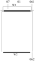
- FIG. 3 is a front view of a backlight module according to an embodiment of the present disclosure.
- FIG. 4 is a schematic diagram of attaching a light-shielding tape in a backlight module according to another embodiment of the present disclosure
- FIG. 5 is a schematic diagram of attaching a light-shielding tape in a backlight module according to still another embodiment of the present disclosure
- FIG. 6 is a schematic view showing a manner of attaching a light-shielding tape in a backlight module according to still another embodiment of the present disclosure
- FIG. 7 is a cross-sectional view of a backlight module according to an embodiment of the present disclosure.
- FIG. 8 is a schematic diagram showing a part of a structure of a backlight module according to an embodiment of the present disclosure.
- FIG. 9 is a schematic diagram showing a part of a structure of a backlight module according to another embodiment of the present disclosure.
- FIG. 10 is a schematic diagram of a manner of attaching a light-shielding tape in a backlight module according to still another embodiment of the present disclosure.
- Figure 11 is a schematic view showing an arrangement of the light-shielding tape of Figure 2A;
- FIG. 12 is a schematic diagram of a display device according to an embodiment of the present disclosure.
- the display panel tends to have a large display area, a narrow bezel, and a thin thickness.
- the light-shielding tape may block a part of the visible area due to its excessive width.
- the width of the light-shielding tape is generally reduced.
- the overlapping area of the light-shielding tape with a reduced width and the plastic frame is small, that is, the bonding area between the light-shielding tape and the plastic frame is reduced. Therefore, when the display device is subjected to the reliability test or during the manufacturing process of the backlight module, the problem that the light-shielding tape is separated from the plastic frame may occur.
- the backlight module includes an upper prism arranged in order from top to bottom. 02, lower prism 03, diffusion sheet 04, light guide plate 05, and reflection sheet 07.
- the backlight module further includes a plastic frame 06 that can be disposed around the upper prism 02, the lower prism 03, the diffusion sheet 04, the light guide plate 05, and the reflection sheet 07, and surrounds the components.
- a plastic frame 06 that can be disposed around the upper prism 02, the lower prism 03, the diffusion sheet 04, the light guide plate 05, and the reflection sheet 07, and surrounds the components.
- the backlight module further includes a light emitting device, and the light emitting device can be disposed between the plastic frame 06 and the light guide plate 05.
- the light emitting device is the LED light 08.
- the light emitting device may also be disposed between the light guide plate 07 and the reflection sheet 07.
- the backlight module further includes a light-shielding tape 01 attached to the plastic frame 06.
- the LED lamp 08 is disposed on the side of the backlight module.
- the backlight module can have the advantages of light weight, thin shape, narrow frame, and low power consumption, so it can be applied to mobile phones and tablets. , laptop or large size TV.
- the light guide plate 05 is used to guide the scattering direction of the light, thereby improving the display brightness of the display panel and the uniformity of the display brightness.
- the upper prism 02 and the lower prism 03 are placed between the diffusion sheet 04 in the backlight module and the display panel for improving the angular distribution of the light.
- the upper prism 02 and the lower prism 03 converge the light uniformly emitted from the diffusion sheet 04 to the respective angles to the axial angle, that is, the front view angle, thereby improving the axial direction without increasing the total luminous flux.
- the reflection sheet 07 can increase the reflectance of the lamp reflection sheet or the bottom reflection sheet, thereby further improving brightness and energy efficiency without colliding with other brightness enhancement techniques.
- the backlight module of the present application is described as an example of a side-lit backlight module in which the display device is disposed on the side of the backlight module.
- the direct-lit backlight module can be disposed between the light guide plate and the reflective sheet. Refer to the related structure of the side-entry backlight module, which will not be described in detail herein.
- the backlight module includes a backlight assembly and a light shielding tape 01 attached to an edge of the backlight assembly.
- the backlight assembly includes an upper surface, a lower surface, and a side surface disposed between the upper surface and the lower surface.
- the light shielding tape 01 includes a first attaching portion 12, a second attaching portion 13, and a third attaching portion 14 which are continuously disposed.
- the first attaching portion 12 is attached to the upper surface of the backlight assembly
- the second attaching portion 13 is attached to the side surface of the backlight assembly
- the third attaching portion 14 is attached to the lower surface of the backlight assembly.
- the upper side of the backlight module refers to the direction of the backlight module near the display panel.
- the upper surface of the backlight assembly refers to a surface of the backlight assembly that is close to the display panel
- the lower surface of the backlight assembly refers to a surface of the backlight assembly that is disposed opposite to the upper surface.
- the backlight assembly includes a plastic frame 06.
- the first attaching portion 12 of the light shielding tape 01 is attached to the upper surface of the plastic frame 06, and the second attaching portion 13 is attached. Attached to the side of the frame 06, the third attachment portion 14 is attached to the lower surface of the frame 06.
- the backlight module further includes a reflective sheet 07 under the plastic frame 06.
- the third attaching portion 14 of the light-shielding tape 01 may have a double-sided adhesive layer, and the third attaching portion 07 is respectively adhered.
- the third attaching portion 14 can replace the lower surface of the plastic frame 06 and the reflective sheet 07 in place of the first adhesive in the conventional backlight module, thereby simplifying the structure and assembly process.
- the gap between the lower surface of the plastic frame 06 and the reflective sheet 07 has the third attaching portion 14 of the light-shielding tape 01, moisture can be prevented from entering the interior of the backlight module during the reliability test, thereby preventing the film and The reflection sheet 07 wrinkles due to moisture.
- the light shielding tape 01 is a stress relieving type tape.
- the substrate of the light-shielding tape 01 may be black PET, and the surface may be coated with a transparent colloid.
- the backlight module further includes a light guide plate 05 , a diffusion sheet 04 , a lower prism 03 , and an upper prism 02 disposed on one side of the plastic frame 06 and sequentially disposed on the reflective sheet 07 .
- the first attaching portion 12 is also attached to a portion of the upper surface of the upper prism 02 near the plastic frame 06.
- the backlight assembly includes a plastic frame 06 and a back plate 15 disposed on a side of the plastic frame 06 and below the plastic frame 06.
- the first attaching portion 12 of the light-shielding tape 01 is attached to the upper surface of the plastic frame 06
- the second attaching portion 13 is attached to the side surface of the back plate
- the third attaching portion 14 is attached to the lower surface of the back plate 15. surface.
- the backlight module further includes a reflective sheet 07 located between the lower surface of the plastic frame 06 and the back plate 15, and disposed on the side of the plastic frame 06 and disposed in order from bottom to top.
- the light guide plate 05, the diffusion sheet 04, the lower prism 03, and the upper prism 02 on the reflection sheet 07 are also attached to a portion of the upper surface of the upper prism 02 near the plastic frame 06.
- the light-shielding tape 01 has a pressure at a boundary position of the first attaching portion 12, the second attaching portion 13, and the third attaching portion 14. Trace M to ensure that the light-shielding tape 01 can be bent at the ridge line.
- the first attaching portion 12 of the light shielding tape 01 is attached to the upper surface of the backlight assembly
- the second attaching portion 13 is attached to the side surface of the backlight assembly
- the third attaching portion is attached.
- 14 is attached to the lower surface of the backlight assembly. That is, the light-shielding tape 01 is attached so as to extend toward the lower surface of the backlight assembly, so that the overlapping area of the light-shielding tape 01 and the backlight assembly can be increased. Therefore, it is possible to solve the problem of insufficient adhesion during assembly due to the small overlapping area of the light-shielding tape 01 and the plastic frame 06 without obstructing the visible area.
- the light-shielding tape 01 is attached so as to extend toward the lower surface of the backlight assembly, and the width of the light-shielding tape 01 can be increased. In this way, problems such as deformation of the tape can be effectively improved, thereby providing a flatter support surface for the display panel. Moreover, the increase in the width of the light-shielding tape 01 increases the bonding area of the light-shielding tape 01 and the backing plate 15, thereby effectively preventing the backing plate 15 from being separated from other components.
- FIG. 3 is a front view of the light shielding tape 01 and the plastic frame 06 in the backlight module according to an embodiment of the present disclosure.
- the bezel 06 includes a first frame 061 and a second frame 062 disposed in parallel with the LED lamp 08. And a third frame 063 and a fourth frame 064 disposed perpendicular to the first frame 061.
- the first frame 061 is on the opposite side of the LED lamp 08, and the second frame 062 is on the same side of the LED lamp 08.
- the first frame 061, the second frame 062, the third frame 063, and the fourth frame 064 together form a plastic frame 06 of a rectangular structure.
- the second frame of the plastic frame 06 At least two retaining wall structures 10 are disposed on the 062.
- the at least two retaining wall structures 10 are respectively located at two ends of the second frame 062 adjacent to the third frame 063 and the fourth frame 064 respectively.
- the at least two retaining wall structures 10 are higher than the other frames of the plastic frame 06, so that the internal components of the backlight module can be effectively protected.
- the light-shielding tape 01 is not attached to the retaining wall structure 10. It should be noted that although the number of the retaining wall structures 10 is shown in FIG. 4, the number of the retaining wall structures 10 in the present invention is not limited thereto.
- the height and shape of the retaining wall structure are not limited in the embodiment of the present disclosure. As long as it can be disposed on the second frame 062 of the plastic frame 06 to protect the internal components of the backlight module.
- the length L1 of the reflective sheet 07 in the backlight module is smaller than the length L2 of the plastic frame 06, and the width W1 of the reflective sheet 07 is smaller than the width W2 of the plastic frame 06. .
- the length of the light-shielding tape 01 attached to the first frame 061 and the second frame 062, respectively, is less than or equal to the width W1 of the reflection sheet 07.
- the light shielding tape 01 is attached to the third frame 063 and the fourth frame 064, respectively.
- the length is less than or equal to the length L1 of the reflection sheet 07.
- FIG. 7 is a cross-sectional view of a backlight module according to an embodiment of the present disclosure.
- the backlight module includes a light shielding tape 01 , an upper prism sheet 02 , a lower prism sheet 03 , a diffusion sheet 04 , a light guide plate 05 , a plastic frame 06 , a reflection sheet 07 , an LED lamp 08 , and a flexible circuit board 09 .
- the LED lamp 08 is soldered on the flexible circuit board 09, and the light-shielding tape 01 is avoided to the visible area.
- the light shielding tape 01 is attached to the outside of the second frame 062 of the plastic frame 06 . Since the flexible circuit board 09 will exceed a portion of the length of the third frame 063 or the fourth frame 064 of the frame 06 during actual assembly, a window is provided outside the second frame 062 of the frame 06 to accommodate the flexible circuit board 09. The opaque tape evades the fenestration when attached to the outside of the second frame 062 of the frame 06.
- FIG. 9 shows a schematic view of the assembly of the light-shielding tape and the plastic frame, with an opening 11 outside the second frame 062 of the plastic frame 06.
- the light-shielding tape 01 includes a plurality of tape segments disposed at intervals along the backlight assembly.
- the bottom side in Fig. 10 is the LED lamp side.
- the shape and spacing of the plurality of tape segments included in the light-shielding tape 01 can be set according to the specific shape and spacing of the first backing rubber replaced by the light-shielding tape 01.
- an embodiment of the present disclosure provides a display device 100 including the backlight module in the embodiment described above.
- the display device 100 has the same structure and advantageous effects as the backlight module provided by the foregoing embodiments. Since the structure and the beneficial effects of the backlight module have been described in detail in the foregoing embodiments, they are not described herein again.
Abstract
L'invention concerne un module de rétroéclairage et un dispositif d'affichage. Le module de rétroéclairage comprend un élément de rétroéclairage et une bande adhésive d'ombrage (01) fixée aux bords de l'élément de rétroéclairage. La bande adhésive d'ombrage (01) comprend une première partie de fixation (12), une deuxième partie de fixation (13) et une troisième partie de fixation (14) disposées consécutivement, la première partie de fixation (12) étant fixée à la surface supérieure de l'élément de rétroéclairage, la deuxième partie de fixation (13) étant fixée à une surface latérale de l'élément de rétroéclairage, et la troisième partie de fixation (14) étant fixée à la surface inférieure de l'élément de rétroéclairage.
Priority Applications (1)
| Application Number | Priority Date | Filing Date | Title |
|---|---|---|---|
| US16/067,079 US11092736B2 (en) | 2017-05-05 | 2017-12-08 | Backlight module and display device |
Applications Claiming Priority (2)
| Application Number | Priority Date | Filing Date | Title |
|---|---|---|---|
| CN201720494801.7U CN207114965U (zh) | 2017-05-05 | 2017-05-05 | 一种侧入式背光模组及显示装置 |
| CN201720494801.7 | 2017-05-05 |
Publications (1)
| Publication Number | Publication Date |
|---|---|
| WO2018201719A1 true WO2018201719A1 (fr) | 2018-11-08 |
Family
ID=61593653
Family Applications (1)
| Application Number | Title | Priority Date | Filing Date |
|---|---|---|---|
| PCT/CN2017/115287 WO2018201719A1 (fr) | 2017-05-05 | 2017-12-08 | Module de rétroéclairage et dispositif d'affichage |
Country Status (3)
| Country | Link |
|---|---|
| US (1) | US11092736B2 (fr) |
| CN (1) | CN207114965U (fr) |
| WO (1) | WO2018201719A1 (fr) |
Families Citing this family (4)
| Publication number | Priority date | Publication date | Assignee | Title |
|---|---|---|---|---|
| CN109031781A (zh) * | 2018-07-27 | 2018-12-18 | 深圳市宝明科技股份有限公司 | 一种用于背光源的具有侧边包覆结构的遮光胶的制备方法 |
| CN111766738A (zh) * | 2020-06-05 | 2020-10-13 | 深圳市隆利科技股份有限公司 | 一种背光模组的反射片及其模切、拼接背胶工艺 |
| TWI738446B (zh) * | 2020-07-31 | 2021-09-01 | 友達光電股份有限公司 | 顯示裝置 |
| CN113138498B (zh) * | 2021-04-22 | 2023-10-31 | 武汉华星光电技术有限公司 | 显示模组 |
Citations (6)
| Publication number | Priority date | Publication date | Assignee | Title |
|---|---|---|---|---|
| JP2006330883A (ja) * | 2005-05-24 | 2006-12-07 | Gunze Ltd | ヘイズ調整用フィルム及びこれを用いたタッチパネル |
| CN102289089A (zh) * | 2011-07-22 | 2011-12-21 | 友达光电(厦门)有限公司 | 平面显示器 |
| CN102436096A (zh) * | 2011-10-28 | 2012-05-02 | 友达光电股份有限公司 | 显示装置及其背光模块 |
| CN102506362A (zh) * | 2011-11-16 | 2012-06-20 | 友达光电(厦门)有限公司 | 背光模组 |
| CN204026361U (zh) * | 2014-08-08 | 2014-12-17 | 厦门天马微电子有限公司 | 背光模组及显示装置 |
| CN104566023A (zh) * | 2014-12-24 | 2015-04-29 | 深圳市华星光电技术有限公司 | 背光模组及显示器 |
Family Cites Families (3)
| Publication number | Priority date | Publication date | Assignee | Title |
|---|---|---|---|---|
| JP6312072B2 (ja) * | 2012-12-26 | 2018-04-18 | 株式会社ジャパンディスプレイ | 液晶表示装置 |
| CN104570474A (zh) * | 2014-12-24 | 2015-04-29 | 深圳市华星光电技术有限公司 | 背光模组及显示器 |
| JP6215867B2 (ja) * | 2015-05-22 | 2017-10-18 | ミネベアミツミ株式会社 | 面状照明装置 |
-
2017
- 2017-05-05 CN CN201720494801.7U patent/CN207114965U/zh active Active
- 2017-12-08 US US16/067,079 patent/US11092736B2/en active Active
- 2017-12-08 WO PCT/CN2017/115287 patent/WO2018201719A1/fr active Application Filing
Patent Citations (6)
| Publication number | Priority date | Publication date | Assignee | Title |
|---|---|---|---|---|
| JP2006330883A (ja) * | 2005-05-24 | 2006-12-07 | Gunze Ltd | ヘイズ調整用フィルム及びこれを用いたタッチパネル |
| CN102289089A (zh) * | 2011-07-22 | 2011-12-21 | 友达光电(厦门)有限公司 | 平面显示器 |
| CN102436096A (zh) * | 2011-10-28 | 2012-05-02 | 友达光电股份有限公司 | 显示装置及其背光模块 |
| CN102506362A (zh) * | 2011-11-16 | 2012-06-20 | 友达光电(厦门)有限公司 | 背光模组 |
| CN204026361U (zh) * | 2014-08-08 | 2014-12-17 | 厦门天马微电子有限公司 | 背光模组及显示装置 |
| CN104566023A (zh) * | 2014-12-24 | 2015-04-29 | 深圳市华星光电技术有限公司 | 背光模组及显示器 |
Also Published As
| Publication number | Publication date |
|---|---|
| US11092736B2 (en) | 2021-08-17 |
| CN207114965U (zh) | 2018-03-16 |
| US20210080641A1 (en) | 2021-03-18 |
Similar Documents
| Publication | Publication Date | Title |
|---|---|---|
| WO2018201719A1 (fr) | Module de rétroéclairage et dispositif d'affichage | |
| WO2019095401A1 (fr) | Module de rétroéclairage à cadre ultra-étroit et dispositif d'affichage | |
| JP5091602B2 (ja) | 面光源装置及びこれを用いた液晶表示装置 | |
| US20130263488A1 (en) | Display device and assembly method thereof | |
| WO2016078124A1 (fr) | Module de rétroéclairage et dispositif d'affichage le comprenant | |
| WO2016078127A1 (fr) | Module de rétroéclairage et dispositif d'affichage | |
| TWI519853B (zh) | 顯示裝置 | |
| US9971086B2 (en) | Backlight module and liquid crystal display | |
| US20180196310A1 (en) | Backlight module and display apparatus | |
| TW201445218A (zh) | 顯示裝置 | |
| TW201441729A (zh) | 顯示裝置 | |
| US20220187528A1 (en) | Backlight module and display panel | |
| JP2014029448A (ja) | 液晶モジュール及び液晶表示装置 | |
| US20150168784A1 (en) | Liquid crystal display device | |
| CN113625488A (zh) | 背光模组及显示装置 | |
| US9234997B2 (en) | Liquid crystal display device and assembly method thereof | |
| US8681288B2 (en) | Backlight unit and display device provided therewith | |
| US8654300B2 (en) | Display apparatus | |
| KR20150093276A (ko) | 표시장치 | |
| WO2017073469A1 (fr) | Dispositif d'éclairage, et dispositif d'affichage | |
| KR20170034651A (ko) | 표시장치 | |
| WO2019000554A1 (fr) | Affichage à cristaux liquides, module de rétroéclairage et procédé d'assemblage associé | |
| JP2017157467A (ja) | 面光源装置、表示装置、及び電子機器 | |
| WO2016173014A1 (fr) | Plaque de guidage de lumière, module de rétro-éclairage et dispositif d'affichage | |
| US20200241358A1 (en) | Display assembly and display device |
Legal Events
| Date | Code | Title | Description |
|---|---|---|---|
| 121 | Ep: the epo has been informed by wipo that ep was designated in this application |
Ref document number: 17908707 Country of ref document: EP Kind code of ref document: A1 |
|
| NENP | Non-entry into the national phase |
Ref country code: DE |
|
| 32PN | Ep: public notification in the ep bulletin as address of the adressee cannot be established |
Free format text: NOTING OF LOSS OF RIGHTS PURSUANT TO RULE 112(1) EPC (EPO FORM 1205A DATED 18.03.2020) |
|
| 122 | Ep: pct application non-entry in european phase |
Ref document number: 17908707 Country of ref document: EP Kind code of ref document: A1 |