WO2018199306A1 - 封止用フィルム、封止構造体及び封止構造体の製造方法 - Google Patents
封止用フィルム、封止構造体及び封止構造体の製造方法 Download PDFInfo
- Publication number
- WO2018199306A1 WO2018199306A1 PCT/JP2018/017256 JP2018017256W WO2018199306A1 WO 2018199306 A1 WO2018199306 A1 WO 2018199306A1 JP 2018017256 W JP2018017256 W JP 2018017256W WO 2018199306 A1 WO2018199306 A1 WO 2018199306A1
- Authority
- WO
- WIPO (PCT)
- Prior art keywords
- sealing
- sealing film
- sealed
- mass
- thermosetting resin
- Prior art date
- Legal status (The legal status is an assumption and is not a legal conclusion. Google has not performed a legal analysis and makes no representation as to the accuracy of the status listed.)
- Ceased
Links
Images

Classifications
-
- C—CHEMISTRY; METALLURGY
- C08—ORGANIC MACROMOLECULAR COMPOUNDS; THEIR PREPARATION OR CHEMICAL WORKING-UP; COMPOSITIONS BASED THEREON
- C08G—MACROMOLECULAR COMPOUNDS OBTAINED OTHERWISE THAN BY REACTIONS ONLY INVOLVING UNSATURATED CARBON-TO-CARBON BONDS
- C08G59/00—Polycondensates containing more than one epoxy group per molecule; Macromolecules obtained by polymerising compounds containing more than one epoxy group per molecule using curing agents or catalysts which react with the epoxy groups
- C08G59/18—Macromolecules obtained by polymerising compounds containing more than one epoxy group per molecule using curing agents or catalysts which react with the epoxy groups ; e.g. general methods of curing
- C08G59/40—Macromolecules obtained by polymerising compounds containing more than one epoxy group per molecule using curing agents or catalysts which react with the epoxy groups ; e.g. general methods of curing characterised by the curing agents used
-
- C—CHEMISTRY; METALLURGY
- C08—ORGANIC MACROMOLECULAR COMPOUNDS; THEIR PREPARATION OR CHEMICAL WORKING-UP; COMPOSITIONS BASED THEREON
- C08G—MACROMOLECULAR COMPOUNDS OBTAINED OTHERWISE THAN BY REACTIONS ONLY INVOLVING UNSATURATED CARBON-TO-CARBON BONDS
- C08G59/00—Polycondensates containing more than one epoxy group per molecule; Macromolecules obtained by polymerising compounds containing more than one epoxy group per molecule using curing agents or catalysts which react with the epoxy groups
- C08G59/18—Macromolecules obtained by polymerising compounds containing more than one epoxy group per molecule using curing agents or catalysts which react with the epoxy groups ; e.g. general methods of curing
- C08G59/40—Macromolecules obtained by polymerising compounds containing more than one epoxy group per molecule using curing agents or catalysts which react with the epoxy groups ; e.g. general methods of curing characterised by the curing agents used
- C08G59/62—Alcohols or phenols
- C08G59/621—Phenols
-
- C—CHEMISTRY; METALLURGY
- C08—ORGANIC MACROMOLECULAR COMPOUNDS; THEIR PREPARATION OR CHEMICAL WORKING-UP; COMPOSITIONS BASED THEREON
- C08G—MACROMOLECULAR COMPOUNDS OBTAINED OTHERWISE THAN BY REACTIONS ONLY INVOLVING UNSATURATED CARBON-TO-CARBON BONDS
- C08G8/00—Condensation polymers of aldehydes or ketones with phenols only
- C08G8/04—Condensation polymers of aldehydes or ketones with phenols only of aldehydes
- C08G8/08—Condensation polymers of aldehydes or ketones with phenols only of aldehydes of formaldehyde, e.g. of formaldehyde formed in situ
- C08G8/12—Condensation polymers of aldehydes or ketones with phenols only of aldehydes of formaldehyde, e.g. of formaldehyde formed in situ with monohydric phenols having only one hydrocarbon substituent ortho on para to the OH group, e.g. p-tert.-butyl phenol
-
- C—CHEMISTRY; METALLURGY
- C08—ORGANIC MACROMOLECULAR COMPOUNDS; THEIR PREPARATION OR CHEMICAL WORKING-UP; COMPOSITIONS BASED THEREON
- C08G—MACROMOLECULAR COMPOUNDS OBTAINED OTHERWISE THAN BY REACTIONS ONLY INVOLVING UNSATURATED CARBON-TO-CARBON BONDS
- C08G8/00—Condensation polymers of aldehydes or ketones with phenols only
- C08G8/04—Condensation polymers of aldehydes or ketones with phenols only of aldehydes
- C08G8/08—Condensation polymers of aldehydes or ketones with phenols only of aldehydes of formaldehyde, e.g. of formaldehyde formed in situ
- C08G8/24—Condensation polymers of aldehydes or ketones with phenols only of aldehydes of formaldehyde, e.g. of formaldehyde formed in situ with mixtures of two or more phenols which are not covered by only one of the groups C08G8/10 - C08G8/20
-
- C—CHEMISTRY; METALLURGY
- C08—ORGANIC MACROMOLECULAR COMPOUNDS; THEIR PREPARATION OR CHEMICAL WORKING-UP; COMPOSITIONS BASED THEREON
- C08J—WORKING-UP; GENERAL PROCESSES OF COMPOUNDING; AFTER-TREATMENT NOT COVERED BY SUBCLASSES C08B, C08C, C08F, C08G or C08H
- C08J5/00—Manufacture of articles or shaped materials containing macromolecular substances
- C08J5/18—Manufacture of films or sheets
-
- C—CHEMISTRY; METALLURGY
- C08—ORGANIC MACROMOLECULAR COMPOUNDS; THEIR PREPARATION OR CHEMICAL WORKING-UP; COMPOSITIONS BASED THEREON
- C08K—Use of inorganic or non-macromolecular organic substances as compounding ingredients
- C08K3/00—Use of inorganic substances as compounding ingredients
- C08K3/01—Use of inorganic substances as compounding ingredients characterized by their specific function
- C08K3/013—Fillers, pigments or reinforcing additives
-
- C—CHEMISTRY; METALLURGY
- C08—ORGANIC MACROMOLECULAR COMPOUNDS; THEIR PREPARATION OR CHEMICAL WORKING-UP; COMPOSITIONS BASED THEREON
- C08L—COMPOSITIONS OF MACROMOLECULAR COMPOUNDS
- C08L61/00—Compositions of condensation polymers of aldehydes or ketones; Compositions of derivatives of such polymers
- C08L61/04—Condensation polymers of aldehydes or ketones with phenols only
- C08L61/06—Condensation polymers of aldehydes or ketones with phenols only of aldehydes with phenols
- C08L61/14—Modified phenol-aldehyde condensates
-
- C—CHEMISTRY; METALLURGY
- C08—ORGANIC MACROMOLECULAR COMPOUNDS; THEIR PREPARATION OR CHEMICAL WORKING-UP; COMPOSITIONS BASED THEREON
- C08L—COMPOSITIONS OF MACROMOLECULAR COMPOUNDS
- C08L63/00—Compositions of epoxy resins; Compositions of derivatives of epoxy resins
-
- H—ELECTRICITY
- H03—ELECTRONIC CIRCUITRY
- H03H—IMPEDANCE NETWORKS, e.g. RESONANT CIRCUITS; RESONATORS
- H03H3/00—Apparatus or processes specially adapted for the manufacture of impedance networks, resonating circuits, resonators
- H03H3/007—Apparatus or processes specially adapted for the manufacture of impedance networks, resonating circuits, resonators for the manufacture of electromechanical resonators or networks
- H03H3/08—Apparatus or processes specially adapted for the manufacture of impedance networks, resonating circuits, resonators for the manufacture of electromechanical resonators or networks for the manufacture of resonators or networks using surface acoustic waves
-
- H—ELECTRICITY
- H03—ELECTRONIC CIRCUITRY
- H03H—IMPEDANCE NETWORKS, e.g. RESONANT CIRCUITS; RESONATORS
- H03H9/00—Networks comprising electromechanical or electro-acoustic elements; Electromechanical resonators
- H03H9/25—Constructional features of resonators using surface acoustic waves
-
- H—ELECTRICITY
- H10—SEMICONDUCTOR DEVICES; ELECTRIC SOLID-STATE DEVICES NOT OTHERWISE PROVIDED FOR
- H10W—GENERIC PACKAGES, INTERCONNECTIONS, CONNECTORS OR OTHER CONSTRUCTIONAL DETAILS OF DEVICES COVERED BY CLASS H10
- H10W74/00—Encapsulations, e.g. protective coatings
- H10W74/10—Encapsulations, e.g. protective coatings characterised by their shape or disposition
-
- H—ELECTRICITY
- H10—SEMICONDUCTOR DEVICES; ELECTRIC SOLID-STATE DEVICES NOT OTHERWISE PROVIDED FOR
- H10W—GENERIC PACKAGES, INTERCONNECTIONS, CONNECTORS OR OTHER CONSTRUCTIONAL DETAILS OF DEVICES COVERED BY CLASS H10
- H10W74/00—Encapsulations, e.g. protective coatings
- H10W74/40—Encapsulations, e.g. protective coatings characterised by their materials
-
- H—ELECTRICITY
- H10—SEMICONDUCTOR DEVICES; ELECTRIC SOLID-STATE DEVICES NOT OTHERWISE PROVIDED FOR
- H10W—GENERIC PACKAGES, INTERCONNECTIONS, CONNECTORS OR OTHER CONSTRUCTIONAL DETAILS OF DEVICES COVERED BY CLASS H10
- H10W74/00—Encapsulations, e.g. protective coatings
- H10W74/40—Encapsulations, e.g. protective coatings characterised by their materials
- H10W74/47—Encapsulations, e.g. protective coatings characterised by their materials comprising organic materials, e.g. plastics or resins
-
- H—ELECTRICITY
- H10—SEMICONDUCTOR DEVICES; ELECTRIC SOLID-STATE DEVICES NOT OTHERWISE PROVIDED FOR
- H10W—GENERIC PACKAGES, INTERCONNECTIONS, CONNECTORS OR OTHER CONSTRUCTIONAL DETAILS OF DEVICES COVERED BY CLASS H10
- H10W72/00—Interconnections or connectors in packages
- H10W72/01—Manufacture or treatment
- H10W72/0198—Manufacture or treatment batch processes
-
- H—ELECTRICITY
- H10—SEMICONDUCTOR DEVICES; ELECTRIC SOLID-STATE DEVICES NOT OTHERWISE PROVIDED FOR
- H10W—GENERIC PACKAGES, INTERCONNECTIONS, CONNECTORS OR OTHER CONSTRUCTIONAL DETAILS OF DEVICES COVERED BY CLASS H10
- H10W74/00—Encapsulations, e.g. protective coatings
-
- H—ELECTRICITY
- H10—SEMICONDUCTOR DEVICES; ELECTRIC SOLID-STATE DEVICES NOT OTHERWISE PROVIDED FOR
- H10W—GENERIC PACKAGES, INTERCONNECTIONS, CONNECTORS OR OTHER CONSTRUCTIONAL DETAILS OF DEVICES COVERED BY CLASS H10
- H10W90/00—Package configurations
- H10W90/701—Package configurations characterised by the relative positions of pads or connectors relative to package parts
- H10W90/721—Package configurations characterised by the relative positions of pads or connectors relative to package parts of bump connectors
- H10W90/724—Package configurations characterised by the relative positions of pads or connectors relative to package parts of bump connectors between a chip and a stacked insulating package substrate, interposer or RDL
Definitions
- the present invention relates to a sealing film, a sealing structure, and a method for manufacturing the sealing structure.
- a SAW device is an electronic component in which a regular comb-shaped electrode is formed on a piezoelectric thin film or a piezoelectric substrate, and an electronic device that can extract an electrical signal in a specific frequency band using surface acoustic waves. It is a part.
- Patent Document 1 a sealing method in which a lid is formed after a rib or the like is formed on a piezoelectric substrate has been performed.
- this method has a problem that it is difficult to reduce the thickness of the electronic component device because the number of steps is increased and the height of the sealing portion is high.
- a sealing material in the hollow region is secured while ensuring excellent embedding property to the object to be sealed. It is difficult to sufficiently suppress the inflow of the resin composition constituting the stop film.
- a sealing material may enter a hollow region between the base material and the object to be sealed.
- the present invention provides a sealing film capable of sufficiently suppressing the inflow of the sealing material into the hollow region between the substrate and the object to be sealed, while being excellent in embedding property to the object to be sealed. It aims at providing the manufacturing method of the sealing structure using the film for a stop, and the said sealing structure.
- the present inventors first considered adjusting the melt viscosity of the resin composition constituting the sealing film to a desired range, adding an elastomer component to the resin composition, and the blending amount of the inorganic filler. It was considered to adjust. However, it has been difficult to solve the above problem only by adjusting the melt viscosity to a desired range by these methods.
- the inventors of the present invention paid attention to the thermosetting resin and conducted further studies. By introducing a specific side chain group into the main skeleton of the specific thermosetting resin, the fluidity of the sealing film was improved.
- the sealing material resin composition constituting the sealing film
- the inventors have found that the inflow can be sufficiently suppressed, and have reached the present invention.
- one aspect of the present invention relates to a sealing film comprising a resin composition containing a thermosetting resin having a structural unit represented by the following formula (1) and an inorganic filler.
- a resin composition containing a thermosetting resin having a structural unit represented by the following formula (1) and an inorganic filler.
- X 1 represents a reactive functional group
- R 1 represents a hydrocarbon group having 2 to 25 carbon atoms.
- the sealing film it is possible to sufficiently suppress the inflow of the sealing material into the hollow region between the substrate and the sealed body while ensuring excellent embeddability to the sealed body. That is, according to the said film for sealing, embedding property and hollow non-filling property can be made compatible. Furthermore, according to the said film for sealing, the glass transition temperature (Tg) after hardening becomes easy enough, and it is easy to improve the reliability (thermal reliability) of a sealing structure.
- Tg glass transition temperature
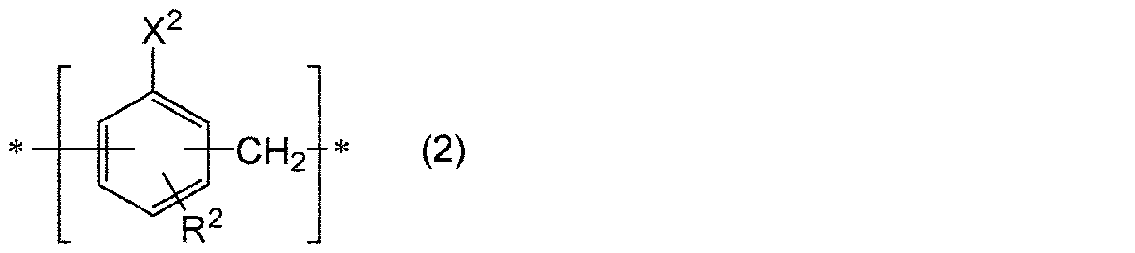
- thermosetting resin may further have a structural unit represented by the following formula (2).
- X 2 represents a reactive functional group
- R 2 represents a hydrogen atom or a phenyl group.
- X 1 may be a hydroxyl group. In this case, it is excellent in heat resistance and flame retardancy. Moreover, such a thermosetting resin can be produced at low cost.
- the above resin composition may further contain an epoxy resin.
- the mechanical strength is excellent, the shrinkage during curing is small, and the dimensional stability is excellent. Moreover, it is excellent in heat resistance, water resistance and chemical resistance, and is excellent in electrical insulation.
- the content of the structural unit represented by the above formula (1) in the thermosetting resin may be 20 mol% or more based on the total amount of the structural unit constituting the thermosetting resin. In this case, embedding property and hollow non-filling property can be achieved at a higher level.
- the weight average molecular weight of the thermosetting resin may be 500 or more.
- the embedding property with respect to the object to be sealed and the hollow non-filling property can be achieved at a higher level.
- the film thickness of the sealing film may be 20 to 250 ⁇ m.
- the above-mentioned sealing film can be suitably used for sealing an object to be sealed provided on a substrate via bumps.
- One aspect of the present invention includes a substrate and a sealed body provided on the substrate via a bump, and a hollow region is provided between the substrate and the sealed body.
- the present invention relates to a method for manufacturing a sealing structure, in which a hollow structure is prepared and the object to be sealed is sealed with the sealing film of the present invention. According to this method, it is possible to obtain a sealed structure in which a sealed body is sufficiently embedded and a hollow region is sufficiently secured.
- the object to be sealed may be a SAW device having an electrode on the hollow region side.
- the SAW device can be sufficiently embedded, and adhesion of the sealing material to the surface of the SAW device having the electrode can be sufficiently suppressed. Therefore, according to the manufacturing method, the reliability of the SAW device can be improved. For the same reason, in the manufacturing method described above, the yield in manufacturing a sealing structure (hollow sealing structure) including such an object to be sealed can be improved.
- One aspect of the present invention is a substrate, a sealed body provided on the substrate via bumps, and a cured product of the sealing film of the present invention that seals the sealed body. And a sealing structure in which a hollow region is provided between the substrate and the object to be sealed. In this sealing structure, the object to be sealed is sufficiently embedded and the hollow region is sufficiently secured.
- the object to be sealed may be a SAW device having an electrode on the hollow region side.
- the SAW device is sufficiently embedded, and adhesion of the sealing material to the surface of the SAW device having the electrode is sufficiently suppressed. Therefore, the reliability of the SAW device is excellent.
- a sealing film that has excellent embeddability to a sealed body and can sufficiently suppress the inflow of a sealing material into a hollow region between the substrate and the sealed body, the sealing A sealing structure using a stop film and a method for manufacturing the sealing structure can be provided.
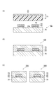
- FIG. 1 is a schematic cross section which shows the film for sealing with a support provided with the film for sealing of embodiment.
- FIG. 2 is a schematic cross-sectional view for explaining an embodiment of a method for producing a hollow sealing structure.
- a numerical range indicated by using “to” indicates a range including the numerical values described before and after “to” as the minimum value and the maximum value, respectively.
- the upper limit value or lower limit value of a numerical range of a certain step may be replaced with the upper limit value or lower limit value of the numerical range of another step.
- the upper limit value or the lower limit value of the numerical range may be replaced with the values shown in the examples.
- “A or B” only needs to include either A or B, and may include both.
- the materials exemplified in the present specification may be used alone or in combination of two or more.
- the content of each component in the composition is the sum of the plurality of substances present in the composition unless there is a specific indication when there are a plurality of substances corresponding to each component in the composition. Means quantity.
- the film for sealing of this embodiment is a film-like resin composition containing a thermosetting component and an inorganic filler.
- the film for sealing of this embodiment contains the thermosetting resin which has a structural unit represented by following formula (1) as a thermosetting component.
- X 1 represents a reactive functional group
- R 1 represents a hydrocarbon group having 2 to 25 carbon atoms.
- the sealing film of the present embodiment is provided between a substrate, a sealed body (for example, an electronic component such as a SAW device) provided on the substrate, and the substrate and the sealed body. It is preferably used for a hollow structure including a hollow region.
- the sealing film of this embodiment the embedding property with respect to a to-be-sealed body and hollow non-filling property can be made compatible. The reason why such an effect is obtained is not clear, but the present inventors presume as follows. That is, in the sealing film of the present embodiment, R 1 in the structural unit represented by the above formula (1) becomes a steric hindrance so that the flow of the thermosetting resin in the sealing film is suppressed. The flow of the resin composition into the hollow region is suppressed.
- R 1 has an appropriate size, and the steric hindrance is alleviated by the shear stress at the time of sealing, so that the embeddability to the object to be sealed is not hindered. For these reasons, it is surmised that the above effect can be obtained according to the sealing film of the present embodiment.
- the sealing material particularly thermosetting resin
- the Tg after curing may decrease, and it may be difficult to ensure the reliability (thermal reliability) of the sealing structure.
- the sealing film of this embodiment it is not necessary to use an excessive amount of elastomer, and since it has a structural unit represented by the above formula (1), it is possible to sufficiently secure Tg after curing. it can.
- thermosetting component examples include a thermosetting resin, a curing agent, and a curing accelerator.
- the thermosetting component may contain a thermosetting resin without containing a curing agent and / or a curing accelerator.
- the thermosetting component contains at least a thermosetting resin having a structural unit represented by the above formula (1) (hereinafter also referred to as “first thermosetting resin”). It may further contain a thermosetting resin other than the thermosetting resin (hereinafter also referred to as “second thermosetting resin”).
- thermosetting resin has at least a structural unit represented by the above formula (1).
- Reactive functional groups represented by X 1 may be any functional group capable of reacting with other reactive functional group and heat.
- the reactive functional group of the first thermosetting resin reacts with other reactive functional groups by heat to form a tertiary crosslinked structure, and the sealing film is cured.
- the reactive functional group include a hydroxyl group, an epoxy group, a carboxyl group, and an isocyanate group.
- a hydroxyl group (phenolic hydroxyl group) is preferable from the viewpoint that it can be produced at low cost, and from the viewpoint of excellent heat resistance and flame retardancy.
- the first thermosetting resin preferably contains a phenol resin.
- the other reactive functional group that reacts with the reactive functional group may be the reactive functional group that the first thermosetting resin has, or the reactive functional group that the second thermosetting resin has. It may be a reactive functional group possessed by the curing agent.
- the hydrocarbon group represented by R 1 may be either linear or branched. Further, the hydrocarbon group may be either saturated or unsaturated. When the hydrocarbon group is an unsaturated hydrocarbon group, the unsaturated hydrocarbon group may have two or more unsaturated bonds.
- the number of carbon atoms of the hydrocarbon group is preferably 4 or more, more preferably 8 or more, further preferably 10 or more, and 15 or more from the viewpoint of better hollow non-fillability. It is particularly preferred. In particular, when the number of carbon atoms of the hydrocarbon group is 15 or more, the elastic modulus can be reduced and the crackability and warpage can be improved.
- the number of carbon atoms in the hydrocarbon group may be 22 or less, 20 or less, or 18 or less from the viewpoint of better embedding.
- the above upper limit value and lower limit value can be arbitrarily combined. Therefore, the carbon number of the hydrocarbon group may be, for example, 4 to 22, 8 to 20, 10 to 18, or 15 to 18.
- the individually described upper limit value and lower limit value can be arbitrarily combined.
- the number of carbons in the main chain of the branched hydrocarbon group may be 2 or more, 4 or more, 6 or more There may be.
- the number of carbon atoms in the main chain of the branched hydrocarbon group may be 22 or less, 20 or less, or 18 or less from the viewpoint of better embedding.
- linear hydrocarbon group examples include — (CH 2 ) 14 CH 3 , — (CH 2 ) 7 CH ⁇ CH (CH 2 ) 5 CH 3 , — (CH 2 ) 7 CH ⁇ CHCH 2 CH ⁇ CH (CH 2 ) 2 CH 3 , — (CH 2 ) 7 CH ⁇ CHCH 2 CH ⁇ CHCH ⁇ CHCH 3 , — (CH 2 ) 7 CH ⁇ CHCH 2 CH ⁇ CHCH 2 CH ⁇ CH 2 and the like.
- Examples of the branched hydrocarbon group include —C (CH 3 ) 2 CH 3 , —C (CH 3 ) 2 CH 2 C (CH 3 ) 2 CH 3 and the like.
- the position of R 1 in the above formula (1) may be any of the ortho, meta, and para positions with respect to —X 1 . From the viewpoint of hardly causing steric hindrance and excellent reactivity, the position of R 1 is preferably a para position with respect to —X 1 .
- the position of the bond (— * and —CH 2 — *) may be any of the ortho, meta, and para positions relative to —X 1 . From the viewpoint of widening the range covered by R 1 , the position of the bond is preferably ortho to X 1 .
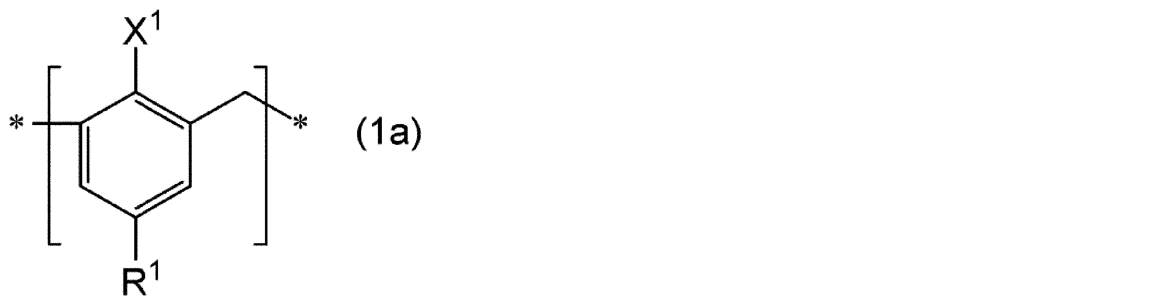
- the structural unit represented by the formula (1) may include a structural unit represented by the following formula (1a). Wherein (1a), is identical to X 1 in the formula (1), R 1 is the same as R 1 in the formula (1). ]
- the first thermosetting resin may consist only of the structural unit represented by the above formula (1).
- the structural unit represented by the formula (1) may be plural.
- the plurality of X 1 may be the same or different, and the plurality of R 1 may be the same or different. Also good.
- the first thermosetting resin may be, for example, a random copolymer composed of a plurality of different structural units, or may be a block copolymer.
- R 1 is a hydrocarbon group having 6 or more carbon atoms
- R 1 is carbon
- X 1 is the same as X 1 in Formula (1)
- R 1A represents a hydrocarbon group having 6 or more carbon atoms.
- R 1B represents a hydrocarbon group having 5 or less carbon atoms.
- the content of the structural unit (1A) constitutes the thermosetting resin from the viewpoint of better hollow non-fillability. Based on the total amount of the structural units to be used, it may be 20 mol% or more, 30 mol% or more, or 40 mol% or more.
- the content of the structural unit (1A) may be 100 mol% or less and 90 mol% or less based on the total amount of the structural units constituting the thermosetting resin from the viewpoint of better embedding. It may be 80 mol% or less. From these viewpoints, the content of the structural unit (1A) may be 20 to 100 mol% or 30 to 90 mol% based on the total amount of the structural units constituting the thermosetting resin. 40 to 80 mol%.
- the content of the structural unit (1B) is a structure constituting the thermosetting resin from the viewpoint of better embedding. Based on the total amount of units, it may be more than 0 mol%, 10 mol% or more, or 20 mol% or more.
- the content of the structural unit (1B) may be 80 mol% or less and 70 mol% or less based on the total amount of the structural units constituting the thermosetting resin from the viewpoint of better hollow non-fillability. It may be 60 mol% or less.
- the content of the structural unit (1B) may be more than 0 mol% and 80 mol% or less based on the total amount of the structural units constituting the thermosetting resin, and is 10 to 70 mol%. It may be 20 to 60 mol%.
- the molar ratio of the structural unit (1A) to the structural unit (1B) may be 0.5 or more from the viewpoint that both the embedding property to the sealed body and the hollow non-filling property can be achieved at a higher level. Moreover, it may be 3.0 or less. Accordingly, the molar ratio of the structural unit (1A) to the structural unit (1B) may be, for example, 0.5 to 3.0.
- the 1st thermosetting resin may further have other structural units other than the structural unit represented by the said Formula (1).
- the structural unit represented by following formula (2) is mentioned, for example.
- X 2 represents a reactive functional group
- R 2 represents a hydrogen atom or a phenyl group.
- the plurality of X 2 may be the same or different
- the plurality of R 2 may be the same or different. Good.
- Examples of reactive functional groups represented by X 2 there may be mentioned the same as the examples of X 1, the same also examples of preferred.
- the position of R 2 in the above formula (2) may be any of the ortho position, the meta position, and the para position with respect to —X 2 . From the viewpoint of hardly causing steric hindrance and excellent reactivity, the position of R 2 is preferably a para position with respect to —X 2 .
- the position of the bond (— * and —CH 2 — *) may be any of the ortho, meta, and para positions relative to —X 2 .
- the volume of the thermosetting resin is reduced, from the viewpoint of improving the reactivity, the position of the bond, compared -X 2, it is preferably ortho position.
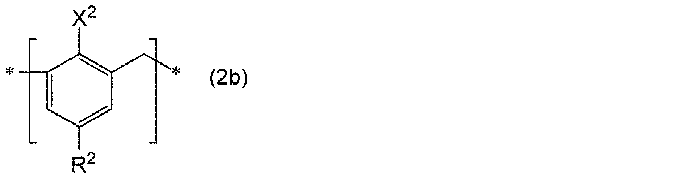
- the structural unit represented by the formula (2) may include a structural unit represented by the following formula (2b). Wherein (2b), X 2 is identical to X 2 in the formula (2), R 2 is identical to R 2 in the formula (2). ]
- the content of the structural unit represented by the above formula (1) in the first thermosetting resin is based on the total amount of the structural units constituting the thermosetting resin from the viewpoint of better hollow non-fillability. 20 mol% or more, 30 mol% or more, or 40 mol% or more.
- the content of the structural unit represented by the above formula (1) in the first thermosetting resin is 100 based on the total amount of the structural units constituting the thermosetting resin from the viewpoint of better embedding.
- the mol% or less may be 90 mol% or less, or 80 mol% or less. From these viewpoints, the content of the structural unit represented by the above formula (1) in the first thermosetting resin is 20 to 100 mol% based on the total amount of the structural units constituting the thermosetting resin. It may be 30 to 90 mol% or 40 to 80 mol%.
- the content of the structural unit represented by the above formula (2) in the first thermosetting resin is 0 based on the total amount of the structural unit constituting the thermosetting resin from the viewpoint of better embedding. It may be more than mol%, may be 10 mol% or more, and may be 20 mol% or more.
- the content of the structural unit represented by the above formula (2) in the first thermosetting resin is based on the total amount of the structural units constituting the thermosetting resin from the viewpoint of better hollow non-fillability. 80 mol% or less, 70 mol% or less, or 60 mol% or less.
- the content of the structural unit represented by the above formula (2) in the first thermosetting resin is more than 0 mol% and 80 mol based on the total amount of the structural units constituting the thermosetting resin. % Or less, 10 to 70 mol%, or 20 to 60 mol%.
- the molar ratio of the structural unit represented by the above formula (1) to the structural unit represented by the above formula (2) in the first thermosetting resin is such that the embeddability to the object to be sealed and the hollow non-filling property. From the viewpoint of achieving compatibility at a higher level, it may be 0.5 or more, and may be 3.0 or less. Therefore, the molar ratio of the structural unit represented by the above formula (1) to the structural unit represented by the above formula (2) may be, for example, 0.5 to 3.0.
- the weight average molecular weight of the first thermosetting resin may be 500 to 1,000,000 from the viewpoint of achieving both higher embeddability to the object to be sealed and hollow non-fillability, and 500 to 500,000. It may be 500 to 300,000.
- a weight average molecular weight is a polystyrene conversion value using the calibration curve by a standard polystyrene by the gel permeation chromatography method (GPC).
- the reactive functional group equivalent of the first thermosetting resin is 100 g / eq. From the viewpoint of increasing the crosslinking point of the resin and increasing the Tg after curing. 110 g / eq. 120 g / eq. Or 130 g / eq. From the same viewpoint, 250 g / eq. Hereinafter, 240 g / eq. Hereinafter, 210 g / eq. Or 200 g / eq. It may be the following. Therefore, the reactive functional group equivalent of the first thermosetting resin is, for example, 100 to 250 g / eq. 110 to 240 g / eq. 120 to 210 g / eq.
- the “reactive functional group equivalent” means the mass (g / eq.) Of the thermosetting resin per 1 equivalent (1 eq.) Of the reactive functional group of the thermosetting resin.
- the reactive functional group is an epoxy group
- the thermosetting resin is dissolved in chloroform, and then acetic acid and a tetraethylammonium bromide acetic acid solution are added to the resulting solution. It is measured by potentiometric titration with a perchloric acid acetic acid standard solution and detecting the end point at which all epoxy groups have reacted.
- an acetylating reagent is added to the thermosetting resin, heated in a glycerin bath, allowed to cool, and then added with a phenolphthalein solution as an indicator. Measured by titration with potassium oxide ethanol solution.
- the first thermosetting resin may be liquid at 25 ° C. from the viewpoint of easily suppressing the occurrence of cracks and cracks on the film surface.
- “Liquid at 25 ° C.” means that the viscosity at 25 ° C. measured with an E-type viscometer is 400 Pa ⁇ s or less.
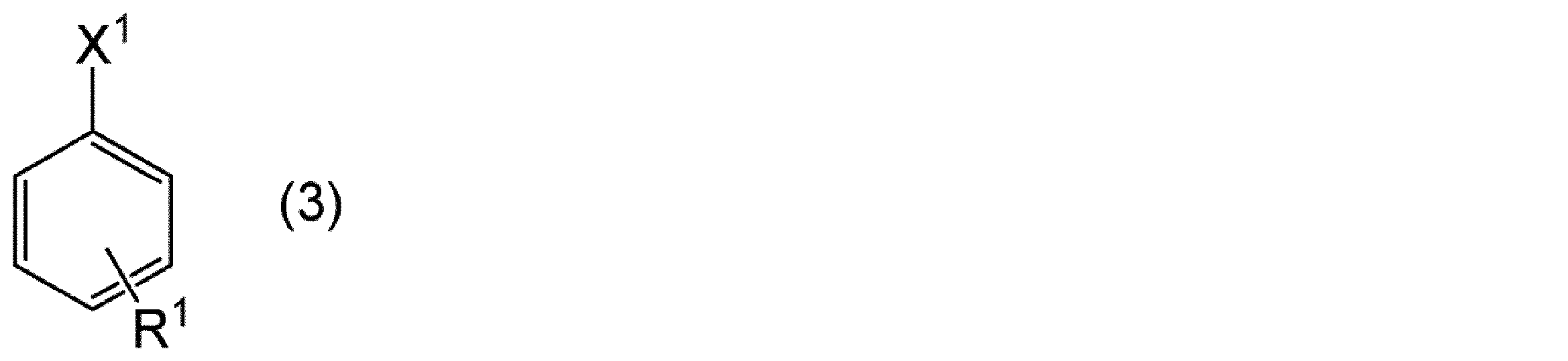
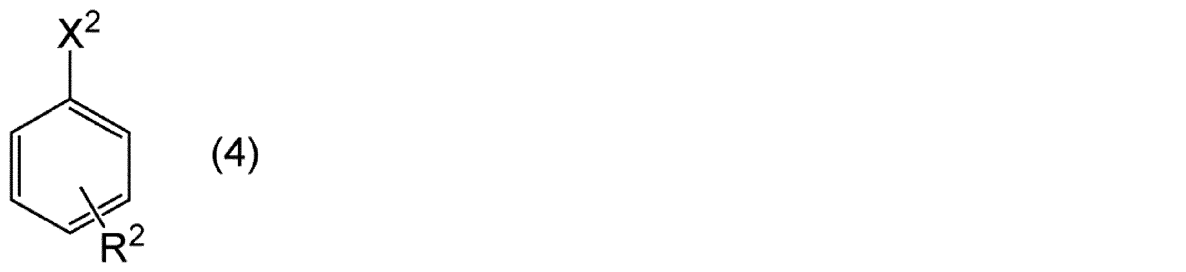
- the resin having the structural unit represented by the above formula (1) can be obtained, for example, by polymerizing a compound represented by the following formula (3) by a conventionally known method. Further, the resin having the structural unit represented by the above formula (1) and the structural unit represented by the above formula (2) includes a compound represented by the following formula (3) and the following formula (4). Can be obtained by copolymerizing the compound represented by formula (1) with a conventionally known method.
- (3) X 1 is identical to X 1 in the formula (1), R 1 is the same as R 1 in the formula (1).
- the position of R 1 may be any of the ortho, meta, and para positions with respect to —X 1 .
- X 2 is identical to X 2 in the formula (2), R 2 is identical to R 2 in the formula (2).
- the position of R 2 may be any of the ortho, meta, and para positions with respect to —X 2 . ]
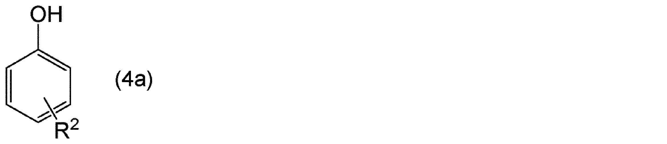
- the first thermosetting resin is a substituent-containing phenol represented by the following formula (3a), formaldehyde, and optionally a substituent represented by the following formula (4a). It can be obtained by reacting the containing phenol.
- each of the first thermosetting resins possesses by adjusting the amount of the substituent-containing phenol represented by the formula (3a) and the substituent-containing phenol represented by the formula (4a). The content of the structural unit can be adjusted.
- R 1 is the same as R 1 in Formula (1).
- the position of R 1 may be any of the ortho, meta, and para positions with respect to —OH.
- [In Formula (4a), R 2 is the same as R 2 in Formula (2).
- the position of R 2 may be any of the ortho, meta, and para positions with respect to —OH. ]
- the first thermosetting resin when X 1 is an epoxy group, the first thermosetting resin reacts the substituent-containing phenol represented by the above formula (3a) with epichlorohydrin in a 30% NaOH solution. Can be obtained.
- each of the first thermosetting resins possesses by adjusting the amount of the substituent-containing phenol represented by the formula (3a) and the substituent-containing phenol represented by the formula (4a). The content of the structural unit can be adjusted.
- the content of the first thermosetting resin may be 1% by mass or more and 3% by mass or more based on the total mass of the sealing film from the viewpoint of better hollow non-fillability. It may be 5 mass% or more.
- the content of the first thermosetting resin may be 50% by mass or less and 30% by mass or less based on the total mass of the sealing film from the viewpoint of better embedding. It may be 10% by mass or less. Accordingly, the content of the first thermosetting resin may be, for example, 1 to 50% by mass, 3 to 30% by mass, or 5 to 5% by mass based on the total mass of the sealing film. It may be 10% by mass.
- thermosetting resin examples include epoxy resin, phenol resin, phenoxy resin, cyanate resin, thermosetting polyimide, melamine resin, urea resin, unsaturated polyester, alkyd resin, and polyurethane.
- the reactive functional group of the second thermosetting resin is preferably a functional group that reacts with the reactive functional group of the first thermosetting resin by heat.
- the reactive functional group that the first thermosetting resin has is a hydroxyl group (phenolic hydroxyl group)
- the reactive functional group that the second thermosetting resin has is preferably an epoxy group.
- the first thermosetting resin is a phenol resin
- the second thermosetting resin is preferably an epoxy resin.
- the reactive functional group that the second thermosetting resin has may be the same as the reactive functional group that the first thermosetting resin has.
- the reactive functional group of the first thermosetting resin is a hydroxyl group (phenolic hydroxyl group)
- the reactive functional group of the second thermosetting resin may be a hydroxyl group (phenolic hydroxyl group).
- a curing agent can be used as the thermosetting component.
- any resin having two or more epoxy groups in one molecule can be used without particular limitation.
- the epoxy resin include bisphenol A type epoxy resin, bisphenol AP type epoxy resin, bisphenol AF type epoxy resin, bisphenol B type epoxy resin, bisphenol BP type epoxy resin, bisphenol C type epoxy resin, bisphenol E type epoxy resin, and bisphenol.
- F type epoxy resin bisphenol G type epoxy resin, bisphenol M type epoxy resin, bisphenol S type epoxy resin (hexanediol bisphenol S diglycidyl ether, etc.), bisphenol P type epoxy resin, bisphenol PH type epoxy resin, bisphenol TMC type epoxy resin , Bisphenol Z type epoxy resin, phenol novolac type epoxy resin, biphenyl type epoxy resin, naphthalene type epoxy resin Dicyclopentadiene type epoxy resins, bixylenol type epoxy resins (such as bixylenol diglycidyl ether), hydrogenated bisphenol A type epoxy resins (such as hydrogenated bisphenol A glycidyl ether), and dibasic acid-modified diglycidyl ethers of these resins
- Type epoxy resin aliphatic epoxy resin and the like.
- An epoxy resin may be used individually by 1 type, and may use 2 or more types together.
- the epoxy resin may be an epoxy resin that is liquid at 25 ° C. (liquid epoxy resin).
- liquid epoxy resins include bisphenol A type glycidyl ether, bisphenol AD type glycidyl ether, bisphenol S type glycidyl ether, bisphenol F type glycidyl ether, water-added bisphenol A type glycidyl ether, and ethylene oxide adduct bisphenol A type.
- Examples thereof include glycidyl ether, propylene oxide adduct bisphenol A-type glycidyl ether, naphthalene resin glycidyl ether, trifunctional or tetrafunctional glycidylamine, and the like.
- epoxy resins for example, trade name “jER825” (bisphenol A type epoxy resin, epoxy equivalent: 175 g / eq.) Manufactured by Mitsubishi Chemical Corporation, trade name “jER806” (bisphenol F manufactured by Mitsubishi Chemical Corporation), and the like.
- Type epoxy resin epoxy equivalent: 160 g / eq.
- Trade name “HP-4032D” manufactured by DIC Corporation (naphthalene type epoxy resin, epoxy equivalent: 141 g / eq.)
- Trade name “EXA-” manufactured by DIC Corporation Flexible toughness epoxy resin such as “4850”, trade name “HP-4700” (tetrafunctional naphthalene type epoxy resin) manufactured by DIC Corporation, trade name “HP-4750” (trifunctional naphthalene type epoxy resin), trade name “ HP-4710 ”(tetrafunctional naphthalene type epoxy resin), trade name“ Epicron N-770 ”( Enol novolac epoxy resin), trade name “Epicron N-660” (cresol novolac epoxy resin) and trade name “Epicron HP-7200H” (dicyclopentadiene epoxy resin), trade name “Nippon Kayaku Co., Ltd.”
- EPPN-502H (trisphenylmethane type epoxy resin) and trade name”
- phenol resin any known phenol resin can be used without particular limitation as long as it has two or more phenolic hydroxyl groups in one molecule.
- phenol resins include resins obtained by condensation or co-condensation of phenols and / or naphthols and aldehydes under an acidic catalyst, biphenyl skeleton type phenol resins, paraxylylene-modified phenol resins, metaxylylene / paraxylylene-modified phenol resins.
- phenols include phenol, cresol, xylenol, resorcinol, catechol, bisphenol A, bisphenol F, and the like.
- naphthols include ⁇ -naphthol, ⁇ -naphthol, dihydroxynaphthalene and the like.
- aldehydes include formaldehyde, acetaldehyde, propionaldehyde, benzaldehyde, salicylaldehyde and the like.
- phenol resins include the product name “PAPS-PN2” (Novolac type phenol resin) manufactured by Asahi Organic Materials Co., Ltd., and the product name “SK Resin HE200C-7” (biphenyl aralkyl type phenol) manufactured by Air Water Co., Ltd. Resin), trade name “HE910-10” (trisphenylmethane type phenol resin), trade names “MEH-7000”, “DL-92”, “H-4” and “HF-1M” manufactured by Meiwa Kasei Co., Ltd.
- the reactive functional group equivalent of the second thermosetting resin is 100 g / eq. From the viewpoint of improving warpage and cracking properties by reducing the number of cross-linking points between resins and reducing curing shrinkage. 120 g / eq. Or 140 g / eq. From the same viewpoint, 500 g / eq. Hereinafter, 400 g / eq. Or 300 g / eq. It may be the following. Therefore, the reactive functional group equivalent of the second thermosetting resin is, for example, 100 to 500 g / eq. 120 to 400 g / eq. 140 to 300 g / eq. It may be.
- the content of the epoxy resin may be 1% by mass or more based on the total mass of the sealing film from the viewpoint of better embedding. 3 mass% or more may be sufficient and 5 mass% or more may be sufficient.
- the content of the epoxy resin may be 50% by mass or less, or 30% by mass or less, based on the total mass of the sealing film, from the viewpoint of better hollow non-fillability. The mass% or less may be sufficient. Therefore, the content of the epoxy resin may be, for example, 1 to 50% by mass, 3 to 30% by mass, or 5 to 10% by mass based on the total mass of the sealing film. May be.
- the content of the liquid epoxy resin is 0 on the basis of the total mass of the sealing film from the viewpoint of easily suppressing the occurrence of cracks and cracks on the film surface.
- 0.5 mass% or more is preferable, 1 mass% or more is more preferable, 3 mass% or more is further preferable, 5 mass% or more is particularly preferable, 7 mass% or more is extremely preferable, and 9 mass% or more is very preferable.
- the content of the liquid epoxy resin is 20% by mass or less based on the total mass of the sealing film from the viewpoint of easily suppressing an excessive increase in the tackiness of the film and from the viewpoint of easily suppressing edge fusion.
- the content of the liquid epoxy resin is preferably 0.5 to 20% by mass, more preferably 1 to 20% by mass, and further preferably 3 to 20% by mass based on the total mass of the sealing film.
- 5 to 20% by mass is particularly preferable, 7 to 15% by mass is very preferable, and 9 to 13% by mass is very preferable.
- the content of the liquid epoxy resin is preferably 20% by mass or more, more preferably 30% by mass or more, based on the total mass of the second thermosetting resin, from the viewpoint of easily suppressing the occurrence of cracks and cracks on the film surface. Preferably, 50 mass% or more is more preferable.
- the content of the liquid epoxy resin is 95 masses on the basis of the total mass of the second thermosetting resin from the viewpoint of easily suppressing an excessive increase in the tackiness of the film and from the viewpoint of easily suppressing the edge fusion. % Or less is preferable, 90 mass% or less is more preferable, and 80 mass% or less is still more preferable.
- the content of the liquid epoxy resin is preferably 20 to 95% by mass, more preferably 30 to 90% by mass, and more preferably 50 to 80% by mass based on the total mass of the second thermosetting resin. Further preferred.
- the content of the liquid epoxy resin may be 100% by mass based on the total mass of the second thermosetting resin.
- the content of the phenol resin may be 1% by mass or more based on the total mass of the sealing film from the viewpoint of better embedding. 3 mass% or more may be sufficient and 5 mass% or more may be sufficient.
- the content of the phenol resin may be 50% by mass or less, or 30% by mass or less, based on the total mass of the sealing film, from the viewpoint of better hollow non-fillability. The mass% or less may be sufficient. Therefore, the content of the phenol resin is, for example, 1 to 50% by mass, 3 to 30% by mass, or 5 to 10% by mass based on the total mass of the sealing film. May be.
- the thermosetting component contains an epoxy resin and a phenol resin from the viewpoint of achieving both higher embeddability and hollow non-fillability with respect to the object to be sealed, and the first heat
- the curable resin contains a phenol resin
- the second thermosetting resin contains an epoxy resin.
- the content of all the epoxy resins and the content of the phenol resin contained in the resin composition are set based on the ratio of the number of moles M2 of epoxy groups to the number of moles M1 of phenolic hydroxyl groups in the resin composition. be able to.
- the ratio (M2 / M1) of the mole number M2 of the epoxy group to the mole number M1 of the phenolic hydroxyl group in the resin composition may be 0.7 or more, 0.8 or more, or 0.9 or more, and 2 It may be 0.0 or less, 1.8 or less, or 1.7 or less. Therefore, the ratio (M2 / M1) may be, for example, 0.7 to 2.0, 0.8 to 1.8, or 0.9 to 1.7.
- curing agent Although it does not specifically limit as a hardening
- curing agent may be used individually by 1 type, and may use 2 or more types together.
- the content of the curing agent may be 1 to 20% by mass or 2 to 15% by mass based on the total mass of the sealing film from the viewpoint of excellent curability of the thermosetting resin. It may be 3 to 10% by mass.
- At least 1 sort (s) chosen from the group which consists of an amine type hardening accelerator and a phosphorus type hardening accelerator is preferable.
- an amine-based curing accelerator is used as the curing accelerator.
- at least one selected from the group consisting of imidazole compounds, aliphatic amines and alicyclic amines is more preferable, and imidazole compounds are more preferable.
- imidazole compound examples include 2-phenyl-4-methylimidazole and 1-benzyl-2-methylimidazole.
- a hardening accelerator may be used individually by 1 type, and may use 2 or more types together.
- Examples of commercially available curing accelerators include “2P4MZ” and “1B2MZ” manufactured by Shikoku Kasei Kogyo Co., Ltd.
- the content of the curing accelerator is preferably in the following range based on the total amount of the thermosetting resin.
- the content of the curing accelerator is preferably 0.01% by mass or more, more preferably 0.1% by mass or more, and still more preferably 0.3% by mass or more from the viewpoint that a sufficient curing acceleration effect can be easily obtained.
- the content of the curing accelerator is such that curing does not easily proceed during the process (for example, coating and drying) at the time of producing the sealing film, or during the storage of the sealing film, And from a viewpoint of being easy to prevent the molding defect accompanying a raise of melt viscosity, 5 mass% or less is preferable, 3 mass% or less is more preferable, and 1.5 mass% or less is still more preferable. From these viewpoints, the content of the curing accelerator is preferably 0.01 to 5% by mass, more preferably 0.1 to 3% by mass, and still more preferably 0.3 to 1.5% by mass.
- inorganic filler As the inorganic filler, conventionally known inorganic fillers can be used and are not particularly limited. Constituent materials of the inorganic filler include silicas (amorphous silica, crystalline silica, fused silica, spherical silica, synthetic silica, hollow silica, etc.), barium sulfate, barium titanate, talc, clay, mica powder, magnesium carbonate , Calcium carbonate, aluminum oxide (alumina), aluminum hydroxide, magnesium oxide, magnesium hydroxide, silicon nitride, aluminum nitride, aluminum borate, boron nitride, barium titanate, strontium titanate, calcium titanate, magnesium titanate, Examples thereof include bismuth titanate, titanium oxide, barium zirconate, and calcium zirconate.
- silicas amorphous silica, crystalline silica, fused silica, spherical silica, synthetic silica, hollow silica, etc.
- an inorganic filler containing silica is preferable.
- an inorganic filler containing aluminum oxide is preferable.
- An inorganic filler may be used individually by 1 type, and may use 2 or more types together.
- the surface of the inorganic filler may be modified.
- the method of surface modification is not particularly limited. Surface modification using a silane coupling agent is preferable from the viewpoint of simple treatment, rich types of functional groups, and easy provision of desired characteristics.
- silane coupling agent examples include alkyl silane, alkoxy silane, vinyl silane, epoxy silane, amino silane, acrylic silane, methacryl silane, mercapto silane, sulfide silane, isocyanate silane, sulfur silane, styryl silane, alkyl chlorosilane, and the like.
- silane coupling agent examples include methyltrimethoxysilane, dimethyldimethoxysilane, trimethylmethoxysilane, methyltriethoxysilane, methyltriphenoxysilane, ethyltrimethoxysilane, n-propyltrimethoxysilane, diisopropyldimethoxysilane, isobutyl.
- the average particle diameter of the inorganic filler is preferably 0.01 ⁇ m or more, more preferably 0.1 ⁇ m or more, and more preferably 0.3 ⁇ m or more from the viewpoint of easily suppressing the aggregation of the inorganic filler and easy dispersion of the inorganic filler. Is more preferable, and 0.5 ⁇ m or more is particularly preferable.
- the average particle diameter of the inorganic filler is preferably 25 ⁇ m or less, more preferably 10 ⁇ m or less, and more preferably 5 ⁇ m or less from the viewpoint of easily suppressing the precipitation of the inorganic filler in the varnish and easy to produce a uniform sealing film. Is more preferable.
- the average particle size of the inorganic filler is preferably 0.01 to 25 ⁇ m, more preferably 0.01 to 10 ⁇ m, still more preferably 0.1 to 10 ⁇ m, particularly preferably 0.3 to 5 ⁇ m, and 0 Very preferably 5 to 5 ⁇ m.
- the average particle diameter of the inorganic filler may be 10 to 18 ⁇ m.
- a combination of a plurality of inorganic fillers having different average particle diameters is preferable.
- a combination in which the average particle diameter of the inorganic filler having the largest average particle diameter is 15 to 25 ⁇ m is preferable.
- the “average particle size” is the particle size at a point corresponding to a volume of 50% when the cumulative frequency distribution curve by the particle size is obtained with the total volume of the particles being 100%, and the particle size distribution using the laser diffraction scattering method It can be measured with a measuring device or the like.
- the average particle diameter of each combined inorganic filler can be confirmed from the average particle diameter of each inorganic filler at the time of mixing, and can be confirmed by measuring the particle size distribution.
- Examples of commercially available inorganic fillers include “DAW20” manufactured by Denka Co., Ltd., trade names “SC550O-SXE” and “SC2050-KC” manufactured by Admatechs Co., Ltd.
- the content of the inorganic filler increases the warpage of the sealing structure (for example, an electronic component device such as a semiconductor device) due to the viewpoint of improving the thermal conductivity and the difference in thermal expansion coefficient from the sealed body. From the viewpoint of being easily suppressed, it may be 70% by mass or more, 75% by mass or more, 80% by mass or more, and 84% by mass based on the total mass of the sealing film. It may be the above.
- the content of the inorganic filler is such that the sealing film is easily cracked in the drying step when the sealing film is produced, and the fluidity is increased due to an increase in the melt viscosity of the sealing film.
- the content of the inorganic filler may be 70 to 93% by mass, 75 to 91% by mass, or 80 to 91% by mass based on the total mass of the sealing film. It may be 84 to 91% by mass or 84 to 88% by mass.
- the said content is content of the inorganic filler except the quantity of the surface treating agent.
- the sealing film of the present embodiment may contain an elastomer (a flexible agent) as necessary. From the viewpoint of excellent dispersibility and solubility, it is preferable to use at least one elastomer selected from the group consisting of polybutadiene particles, styrene butadiene particles, acrylic elastomers, silicone powders, silicone oils, and silicone oligomers. One type of elastomer may be used alone, or two or more types may be used in combination.
- the average particle diameter of the elastomer When the elastomer is particulate, there is no particular limitation on the average particle diameter of the elastomer. In eWLB (Embedded Wafer-Level Ball Grid Array) applications, it is necessary to embed between semiconductor elements, so when using a sealing film for eWLB applications, the average particle size of the elastomer may be 50 ⁇ m or less. preferable. The average particle diameter of the elastomer is preferably 0.1 ⁇ m or more from the viewpoint of excellent dispersibility of the elastomer.
- elastomers examples include “SG-280 EK23”, “SG-70L”, “WS-023 EK30”, which are acrylic elastomers manufactured by Nagase ChemteX Corporation. Also, some commercially available elastomer components are dispersed in advance in a liquid resin (for example, a liquid epoxy resin) instead of the elastomer alone, but can be used without any problem. Examples of such commercially available products include “MX-136” and “MX-965” manufactured by Kaneka Corporation.
- the content of the elastomer may be 1% by mass or more based on the total amount of the thermosetting component and the elastomer, and may be 5% by mass or more, from the viewpoint of better hollow non-fillability. It may be 10% by mass or more.
- the content of the elastomer is a thermosetting component from the viewpoint that the embedding property is better and that a sufficient Tg is easily obtained after curing, and the reliability (thermal reliability) of the sealing structure is improved. And 30% by mass or less, or 25% by mass or less, or 20% by mass or less, based on the total amount of the elastomer. From the above, the content of the elastomer may be 1 to 30% by mass or 5 to 25% by mass or 10 to 20% by mass based on the total amount of the thermosetting component and the elastomer. It may be the following.
- the sealing film of the present embodiment can further contain other additives.
- additives include pigments, dyes, mold release agents, antioxidants, surface tension adjusting agents and the like.
- the sealing film of the present embodiment may contain a solvent (for example, a solvent used for manufacturing the sealing film).
- the solvent may be a conventionally known organic solvent.
- the organic solvent may be a solvent that can dissolve components other than inorganic fillers, such as aliphatic hydrocarbons, aromatic hydrocarbons, terpenes, halogens, esters, ketones, alcohols, aldehydes, etc. Is mentioned.
- a solvent may be used individually by 1 type and may use 2 or more types together.
- the solvent may be at least one selected from the group consisting of esters, ketones, and alcohols from the viewpoint of low environmental burden and the ability to easily dissolve the thermosetting component. Among these, when the solvent is a ketone, the thermosetting component is particularly easily dissolved.
- the solvent may be at least one selected from the group consisting of acetone, methyl ethyl ketone, and methyl isobutyl ketone from the viewpoint of little volatilization at room temperature (25 ° C.) and easy removal during drying.
- the content of a solvent (such as an organic solvent) contained in the sealing film is preferably in the following range based on the total mass of the sealing film.
- the content of the solvent is from the viewpoint of easily suppressing the sealing film from becoming brittle and causing problems such as cracking of the sealing film, and the minimum melt viscosity to be increased and the embedding property to be lowered. It may be 2% by mass or more, 0.3% by mass or more, 0.5% by mass or more, 0.6% by mass or more, 0.7% by mass It may be the above.
- the content of the solvent is a problem that the adhesiveness of the sealing film becomes too strong and the handleability is lowered, and a problem such as foaming due to the volatilization of the solvent (organic solvent, etc.) during thermal curing of the sealing film. May be 1.5 mass% or less, and may be 1 mass% or less. From these viewpoints, the solvent content may be 0.2 to 1.5% by mass, 0.3 to 1% by mass, or 0.5 to 1% by mass. It may be 0.6 to 1% by mass or 0.7 to 1% by mass.
- the thickness (film thickness) of the sealing film may be 20 ⁇ m or more, 30 ⁇ m or more, or 50 ⁇ m or more from the viewpoint of easily suppressing variation in the in-plane thickness during coating. It may be 100 ⁇ m or more.
- the thickness of the sealing film may be 250 ⁇ m or less, 200 ⁇ m or less, or 150 ⁇ m or less from the viewpoint that a certain drying property is easily obtained in the depth direction during coating. From these viewpoints, the thickness of the sealing film may be 20 to 250 ⁇ m, 30 to 250 ⁇ m, 50 to 200 ⁇ m, or 100 to 150 ⁇ m. Further, a plurality of sealing films can be laminated to produce a sealing film having a thickness exceeding 250 ⁇ m.
- the glass transition temperature Tg after curing of the sealing film may be 80 to 180 ° C. or 80 to 165 ° C. from the viewpoint of the reliability (thermal reliability) of the obtained sealing structure. 80 to 150 ° C.
- the glass transition temperature Tg after curing of the sealing film can be adjusted by the type and content of the thermosetting component, the type and content of the elastomer component, and the like.
- the glass transition temperature Tg can be measured by the method described in the examples.
- the minimum melt viscosity (minimum melt viscosity) at 35 to 200 ° C. of the sealing film may be 100 to 10,000 Pa ⁇ s, or 250 to 8500 Pa ⁇ s from the viewpoint of better embedding. It may be 500 to 7000 Pa ⁇ s.
- the maximum melt viscosity (maximum melt viscosity) at 70 to 90 ° C. of the sealing film may be 500 to 25000 Pa ⁇ s, or 4000 to 20000 Pa ⁇ s from the viewpoint of better hollow non-fillability. It may be 6000 to 15000 Pa ⁇ s.
- the said minimum melt viscosity and the maximum melt viscosity can be calculated
- the sealing film of the present embodiment is suitably used for sealing the object to be sealed in the hollow structure, but the structure to be sealed does not have a hollow structure. May be.
- the sealing film of this embodiment can also be used, for example, for sealing semiconductor devices, embedding electronic components arranged on a printed wiring board, and the like.
- the sealing film of this embodiment can also be used as a sealing film with a support, for example.
- a support-equipped sealing film 10 shown in FIG. 1 includes a support 1 and a sealing film 2 provided on the support 1.
- a polymer film, a metal foil or the like can be used as the support 1, a polymer film, a metal foil or the like.
- the polymer film include polyolefin films such as polyethylene films and polypropylene films; vinyl films such as polyvinyl chloride films; polyester films such as polyethylene terephthalate films; polycarbonate films; acetylcellulose films;
- the metal foil include copper foil and aluminum foil.
- the thickness of the support 1 is not particularly limited, but may be 2 to 200 ⁇ m from the viewpoint of excellent workability and drying property.
- the thickness of the support 1 is 2 ⁇ m or more, it is easy to suppress problems such as breakage of the support during coating, deflection of the support due to the weight of the varnish, and the like.
- the thickness of the support 1 is 200 ⁇ m or less, it is easy to suppress problems that prevent drying of the solvent in the varnish when hot air is blown from both the coated surface and the back surface in the drying step.
- the support 1 may not be used. Moreover, you may arrange
- a polymer film, a metal foil or the like can be used as the protective layer.
- the polymer film include polyolefin films such as polyethylene films and polypropylene films; vinyl films such as polyvinyl chloride films; polyester films such as polyethylene terephthalate films; polycarbonate films; acetylcellulose films; it can.
- the metal foil include copper foil and aluminum foil.
- the sealing film of the present embodiment can be produced as follows.
- a varnish (varnish-like resin composition) is prepared by mixing the components (thermosetting resin, curing agent, curing accelerator, inorganic filler, solvent, etc.) of the resin composition of this embodiment.
- the mixing method is not particularly limited, and a mill, a mixer, and a stirring blade can be used.
- a solvent such as an organic solvent
- the sealing varnish can be produced by applying the varnish thus produced to a support (film-like support etc.) and then drying by heating with hot air blowing or the like.
- a coating (coating) method For example, coating apparatuses, such as a comma coater, a bar coater, a kiss coater, a roll coater, a gravure coater, a die coater, can be used.
- the sealing structure which concerns on this embodiment is provided with a to-be-sealed body and the sealing part which seals the said to-be-sealed body.
- the sealing part is a cured product of the sealing film of the present embodiment, and includes a cured product of the resin composition of the present embodiment.
- the sealing structure may be a hollow sealing structure having a hollow structure.
- the hollow sealing structure includes, for example, a substrate, an object to be sealed provided on the substrate, a hollow area provided between the substrate and the object to be sealed, and a seal that seals the object to be sealed. A stop portion.
- the sealing structure of this embodiment may include a plurality of objects to be sealed. The plurality of objects to be sealed may be of the same type or different types.
- the sealing structure is, for example, an electronic component device.
- the electronic component device includes an electronic component as a sealed body. Examples of the electronic component include a semiconductor element; a semiconductor wafer; an integrated circuit; a semiconductor device; a filter such as a SAW filter; a passive component such as a sensor. A semiconductor element obtained by separating a semiconductor wafer may be used.
- the electronic component device may be a semiconductor device including a semiconductor element or a semiconductor wafer as an electronic component; a printed wiring board or the like.
- Examples of such an object to be sealed include electronic components such as a SAW device such as a SAW filter.
- a SAW device such as a SAW filter.
- the surface of the piezoelectric substrate on which an electrode (for example, IDT (Inter Digital Transducer) as a pair of comb electrodes) is attached becomes a movable part.
- IDT Inter Digital Transducer
- the hollow sealing structure is an electronic component device and the object to be sealed is a SAW device will be described.
- FIG. 2 is a schematic cross-sectional view for explaining an embodiment of a method for producing a semiconductor device, which is an electronic component device, as an embodiment of a method for producing a hollow sealing structure.
- a hollow structure including a substrate 30 and a plurality of SAW devices 20 arranged side by side via bumps 40 on the substrate 30 as an object to be sealed (an object to be embedded).
- the surface on the SAW device 20 side of the substrate 30 and the surface on the sealing film 2 side of the sealing film with support 10 are made to face each other ((a) in FIG. 2).
- the hollow structure 60 has a hollow region 50
- the SAW device 20 has a movable portion on the surface 20a on the hollow region 50 side (substrate 30 side).
- the sealing film 2 in which the SAW device 20 is embedded after the SAW device 20 is embedded in the sealing film 2 by pressing (laminating) the sealing film 2 on the SAW device 20 under heating. Is cured to obtain a cured product of the sealing film (sealed portion including a cured product of the resin composition) 2a ((b) of FIG. 2). Thereby, the electronic component device 100 can be obtained.
- the laminator used for laminating is not particularly limited, and examples thereof include a roll type and a balloon type laminator.
- the laminator may be a balloon type capable of vacuum pressurization from the viewpoint of excellent embeddability.
- Lamination is usually performed below the softening point of the support.
- the laminating temperature (sealing temperature) is preferably near the minimum melt viscosity of the sealing film.
- the laminating temperature is, for example, 60 to 140 ° C.
- the pressure at the time of laminating varies depending on the size, density, etc. of an object to be sealed (for example, an electronic component such as a semiconductor element).
- the pressure during lamination may be, for example, in the range of 0.2 to 1.5 MPa, or in the range of 0.3 to 1.0 MPa.
- the lamination time is not particularly limited, but may be 20 to 600 seconds, 30 to 300 seconds, or 40 to 120 seconds.
- the sealing film can be cured, for example, in the air or under an inert gas.
- the curing temperature is not particularly limited, and may be 80 to 280 ° C., 100 to 240 ° C., or 120 to 200 ° C. When the curing temperature is 80 ° C. or higher, the curing of the sealing film proceeds sufficiently, and the occurrence of defects can be suppressed. When the curing temperature is 280 ° C. or lower, the occurrence of heat damage to other materials tends to be suppressed.
- the curing time (heating time) is not particularly limited, and may be 30 to 600 minutes, 45 to 300 minutes, or 60 to 240 minutes. When the curing time is within these ranges, curing of the sealing film proceeds sufficiently, and better production efficiency can be obtained. Moreover, you may combine several conditions for hardening conditions.
- a plurality of electronic component devices 200 may be obtained by further dividing the electronic component device 100 with a dicing cutter or the like ((c) in FIG. 2).
- the hollow region 50 between the substrate 30 and the sealed body is secured while ensuring excellent embeddability to the sealed body (for example, the SAW device 20). Inflow of the sealing material can be sufficiently suppressed.
- the sealing film 2 is thermally cured to provide the hollow sealing including the SAW device 20 embedded in the cured product 2a.
- a structure electronic component device
- a sealed structure may be obtained by a compression mold using a compression mold device, or a sealed structure may be obtained by press molding using a hydraulic press.
- the temperature (sealing temperature) at which the object to be sealed is sealed with a compression mold and a hydraulic press may be the same as the above-described laminating temperature.
- A1 Bisphenol F type epoxy resin (manufactured by Mitsubishi Chemical Corporation, trade name “jER806”, epoxy group equivalent: 160 g / eq.)
- B1 Hydrocarbon group-containing phenol resin (phenolic hydroxyl group equivalent: 140 g / eq., Weight average molecular weight: 120,000)
- B2 Hydrocarbon group-containing phenol resin (phenolic hydroxyl group equivalent: 185 g / eq., Weight average molecular weight: 120,000)
- B3 Hydrocarbon group-containing phenol resin (phenolic hydroxyl group equivalent: 243 g / eq., Weight average molecular weight: 120,000)
- B4 Hydrocarbon group-containing phenol resin (phenolic hydroxyl group equivalent: 205 g / eq., Weight average molecular weight: 120,000)
- B5 Novolac-type phenol resin (Maywa Kasei Co., Ltd., trade name “DL-92”, phenolic hydroxyl group equivalent: 103
- C1 Imidazole (manufactured by Shikoku Kasei Kogyo Co., Ltd., trade name “2P4MZ”)
- (Elastomer) D1 Acrylic acid ester polymer (manufactured by Nagase ChemteX Corporation, trade name “SG-280 EK23”, molecular weight 900,000)
- E1 Silica (manufactured by Admatechs Co., Ltd., trade name “5 ⁇ m SX-E2”, phenylaminosilane treatment, average particle size: 5.8 ⁇ m)
- B1 to B4 were prepared according to the method described in JP-A-2015-89949. Specifically, it was prepared by the following method.
- Example 1 The amount (part by mass) of A1, B1, D1, and E1 shown in Table 1 was added to a 0.5 L polyethylene container, and the mixture was stirred with a stirring blade to disperse the inorganic filler E1. Then, C1 of the quantity (mass part) shown in Table 1 was added, and also it stirred for 30 minutes. The obtained mixture was filtered through nylon # 150 mesh (opening 106 ⁇ m), and the filtrate was collected. This obtained the varnish-like epoxy resin composition. This varnish-like epoxy resin composition was apply
- ⁇ Coating head method Comma ⁇ Coating and drying speed: 1 m / min ⁇ Drying conditions (temperature / furnace length): 80 ° C./1.5 m, 100 ° C./1.5 m Support: PET film with a thickness of 38 ⁇ m
- the surface of the sealing film was protected by disposing a protective layer (polyethylene terephthalate film having a thickness of 50 ⁇ m) on the side opposite to the support in the sealing film.
- a protective layer polyethylene terephthalate film having a thickness of 50 ⁇ m
- Example 2 to 4 and Comparative Examples 1 to 2 Examples 2 to 4 and Comparative Example 1 were the same as Example 1 except that the types and blending amounts of the materials (A1, B1, C1, D1, and E1) used were changed as shown in Table 1.
- a varnish-like epoxy resin composition of ⁇ 2 was obtained.
- the varnish-like epoxy resin compositions of Examples 2 to 4 and Comparative Examples 1 and 2 were used in place of the varnish-like epoxy resin of Example 1, the Examples The sealing films (thickness 110 ⁇ m) of 2 to 4 and Comparative Examples 1 and 2 were obtained.
- ⁇ Evaluation method> The following methods were used to evaluate the melt viscosity, embedding property and hollow non-fillability of the sealing film, and the elastic modulus and glass transition temperature after curing of the sealing film.
- Evaluation C Embeddability and hollow non-fillability at a melt viscosity of 7000 Pa ⁇ s Based on the measurement result of the melt viscosity in Evaluation A, sealing was performed at a temperature at which the melt viscosity of the sealing film was 7000 Pa ⁇ s. Except for this, the embedding property and the hollow non-filling property were evaluated in the same manner as in the evaluation B.
- the sealing film with copper foil was attached to a SUS plate, and the sealing film was cured under the following conditions to obtain a cured product of the sealing film with copper foil (epoxy resin cured body with copper foil).
- ⁇ Oven SAFETY OVEN SPH-201 manufactured by ESPEC CORP.
- the glass transition temperature Tg When the glass transition temperature Tg is low, the thermal reliability of the sealing structure deteriorates. Therefore, the glass transition temperature was evaluated according to the following criteria.
- both embedding property and hollow non-filling property could be achieved at a sealing temperature of 70 ° C. Moreover, even when sealing was performed at a temperature at which the melt viscosity was 7000 Pa ⁇ s, both embeddability and hollow non-fillability could be achieved.
- Comparative Example 1 the desired embedding property was not obtained at a sealing temperature of 70 ° C., and the desired hollow non-filling property was not obtained even at a temperature at which the melt viscosity was 7000 Pa ⁇ s.
- the desired hollow non-filling property was not obtained in any of Evaluation A (sealing temperature was 70 ° C.) and Evaluation B (melt viscosity was 7000 Pa ⁇ s).
- SYMBOLS 1 Support body, 2 ... Sealing film, 2a ... Hardened
Landscapes
- Chemical & Material Sciences (AREA)
- Health & Medical Sciences (AREA)
- Chemical Kinetics & Catalysis (AREA)
- Medicinal Chemistry (AREA)
- Polymers & Plastics (AREA)
- Organic Chemistry (AREA)
- Engineering & Computer Science (AREA)
- Manufacturing & Machinery (AREA)
- Physics & Mathematics (AREA)
- Acoustics & Sound (AREA)
- Materials Engineering (AREA)
- Structures Or Materials For Encapsulating Or Coating Semiconductor Devices Or Solid State Devices (AREA)
- Epoxy Resins (AREA)
- Compositions Of Macromolecular Compounds (AREA)
Abstract
Description
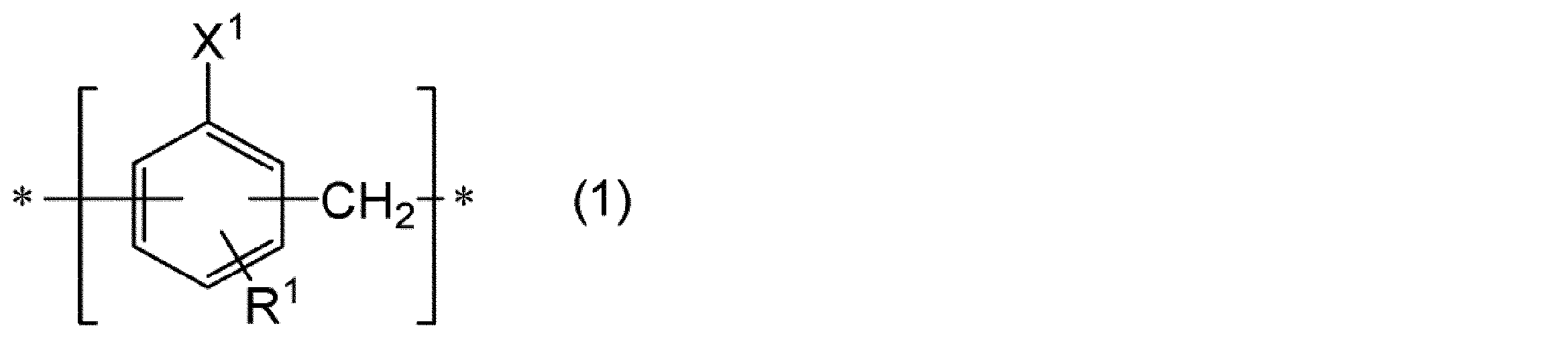

本実施形態の封止用フィルムは、熱硬化性成分及び無機充填材を含有するフィルム状の樹脂組成物である。本実施形態の封止用フィルムは、熱硬化性成分として、下記式(1)で表される構造単位を有する熱硬化性樹脂を含有する。
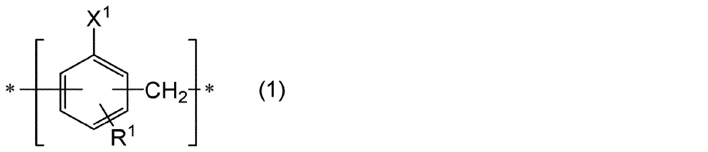
熱硬化性成分としては、熱硬化性樹脂、硬化剤、硬化促進剤等が挙げられる。熱硬化性成分は、硬化剤及び/又は硬化促進剤を含むことなく、熱硬化性樹脂を含んでいてもよい。また、熱硬化性成分は、少なくとも上記式(1)で表される構造単位を有する熱硬化性樹脂(以下、「第1の熱硬化性樹脂」ともいう。)を含有するが、第1の熱硬化性樹脂以外の熱硬化性樹脂(以下、「第2の熱硬化性樹脂」ともいう。)を更に含有していてもよい。
第1の熱硬化性樹脂は少なくとも上記式(1)で表される構造単位を有する。



第2の熱硬化性樹脂としては、エポキシ樹脂、フェノール樹脂、フェノキシ樹脂、シアネート樹脂、熱硬化性ポリイミド、メラミン樹脂、尿素樹脂、不飽和ポリエステル、アルキド樹脂、ポリウレタン等が挙げられる。第2の熱硬化性樹脂が有する反応性官能基は、第1の熱硬化性樹脂が有する反応性官能基と熱により反応する官能基であることが好ましい。例えば、第1の熱硬化性樹脂が有する反応性官能基が水酸基(フェノール性水酸基)である場合、第2の熱硬化性樹脂が有する反応性官能基はエポキシ基であることが好ましい。換言すれば、第1の熱硬化性樹脂がフェノール樹脂である場合、第2の熱硬化性樹脂はエポキシ樹脂であることが好ましい。この場合、機械的強度に優れると共に、硬化時の収縮が少なく、寸法安定性に優れる。また、耐熱性、耐水性及び耐薬品性に優れ、電気絶縁性に優れる。第2の熱硬化性樹脂が有する反応性官能基は、第1の熱硬化性樹脂が有する反応性官能基と同一であってよい。例えば、第1の熱硬化性樹脂が有する反応性官能基が水酸基(フェノール性水酸基)である場合、第2の熱硬化性樹脂が有する反応性官能基は水酸基(フェノール性水酸基)であってよい。この場合、熱硬化性成分として硬化剤を用いることができる。
硬化剤(熱硬化性樹脂に該当する成分は除く)としては、特に限定されないが、フェノール系硬化剤、酸無水物系硬化剤、活性エステル系硬化剤、シアネートエステル系硬化剤などが挙げられる。硬化剤は、1種を単独で用いてもよく、2種以上を併用してもよい。
硬化促進剤としては、特に制限なく用いることができるが、アミン系の硬化促進剤及びリン系の硬化促進剤からなる群より選ばれる少なくとも1種が好ましい。硬化促進剤としては、特に、優れた熱伝導率を有する硬化物が得られやすい観点、誘導体が豊富である観点、及び、所望の活性温度が得られやすい観点から、アミン系の硬化促進剤が好ましく、イミダゾール化合物、脂肪族アミン及び脂環族アミンからなる群より選ばれる少なくとも1種がより好ましく、イミダゾール化合物が更に好ましい。イミダゾール化合物としては、2-フェニル-4-メチルイミダゾール、1-ベンジル-2-メチルイミダゾール等が挙げられる。硬化促進剤は、1種を単独で用いてもよく、2種以上を併用してもよい。硬化促進剤の市販品としては、四国化成工業株式会社製の「2P4MZ」及び「1B2MZ」等が挙げられる。
無機充填剤としては、従来公知の無機充填剤を使用でき、特に限定されない。無機充填剤の構成材料としては、シリカ類(無定形シリカ、結晶性シリカ、溶融シリカ、球状シリカ、合成シリカ、中空シリカ等)、硫酸バリウム、チタン酸バリウム、タルク、クレー、雲母粉、炭酸マグネシウム、炭酸カルシウム、酸化アルミニウム(アルミナ)、水酸化アルミニウム、酸化マグネシウム、水酸化マグネシウム、窒化ケイ素、窒化アルミニウム、ホウ酸アルミニウム、窒化ホウ素、チタン酸バリウム、チタン酸ストロンチウム、チタン酸カルシウム、チタン酸マグネシウム、チタン酸ビスマス、酸化チタン、ジルコン酸バリウム、ジルコン酸カルシウムなどが挙げられる。表面改質(例えば、シラン化合物による表面処理)等により、樹脂組成物中での分散性の向上効果、及び、ワニス中での沈降抑制効果が得られやすい観点、並びに、比較的小さい熱膨張率を有するために所望の硬化膜特性が得られやすい観点では、シリカ類を含む無機充填材が好ましい。高い熱伝導性が得られる観点では、酸化アルミニウムを含む無機充填材が好ましい。無機充填剤は、1種を単独で用いてもよく、2種以上を併用してもよい。
本実施形態の封止用フィルムは、必要に応じて、エラストマー(可とう剤)を含有してもよい。エラストマーは、分散性及び溶解性に優れる観点から、ポリブタジエン粒子、スチレンブタジエン粒子、アクリル系エラストマー、シリコーンパウダ、シリコーンオイル及びシリコーンオリゴマからなる群より選ばれる少なくとも1種を用いることが好ましい。エラストマーは、1種を単独で用いてもよく、2種以上を併用してもよい。
本実施形態の封止用フィルムは、他の添加剤を更に含有することができる。このような添加剤の具体例としては、顔料、染料、離型剤、酸化防止剤、表面張力調整剤等を挙げることができる。
本実施形態の封止用フィルムは、具体的には、次のようにして作製することができる。
本実施形態に係る封止構造体は、被封止体と、当該被封止体を封止する封止部と、を備える。封止部は、本実施形態の封止用フィルムの硬化物であり、本実施形態の樹脂組成物の硬化物を含んでいる。封止構造体は、中空構造を有する中空封止構造体であってよい。中空封止構造体は、例えば、基板と、基板上に設けられた被封止体と、基板と被封止体との間に設けられた中空領域と、被封止体を封止する封止部と、を備える。本実施形態の封止構造体は、複数の被封止体を備えていてもよい。複数の被封止体は、互いに同一の種類であってもよく、互いに異なる種類であってもよい。
A1:ビスフェノールF型エポキシ樹脂(三菱化学株式会社製、商品名「jER806」、エポキシ基当量:160g/eq.)
B1:炭化水素基含有フェノール樹脂(フェノール性水酸基当量:140g/eq.、重量平均分子量:12万)
B2:炭化水素基含有フェノール樹脂(フェノール性水酸基当量:185g/eq.、重量平均分子量:12万)
B3:炭化水素基含有フェノール樹脂(フェノール性水酸基当量:243g/eq.、重量平均分子量:12万)
B4:炭化水素基含有フェノール樹脂(フェノール性水酸基当量:205g/eq.、重量平均分子量:12万)
B5:ノボラック型フェノール樹脂(明和化成株式会社製、商品名「DL-92」、フェノール性水酸基当量:103g/eq.、重量平均分子量:5万)
C1:イミダゾール(四国化成工業株式会社製、商品名「2P4MZ」)
D1:アクリル酸エステルポリマー(ナガセケムテックス株式会社製、商品名「SG-280 EK23」、分子量90万)
E1:シリカ(株式会社アドマテックス製、商品名「5μm SX-E2」、フェニルアミノシラン処理、平均粒径:5.8μm)
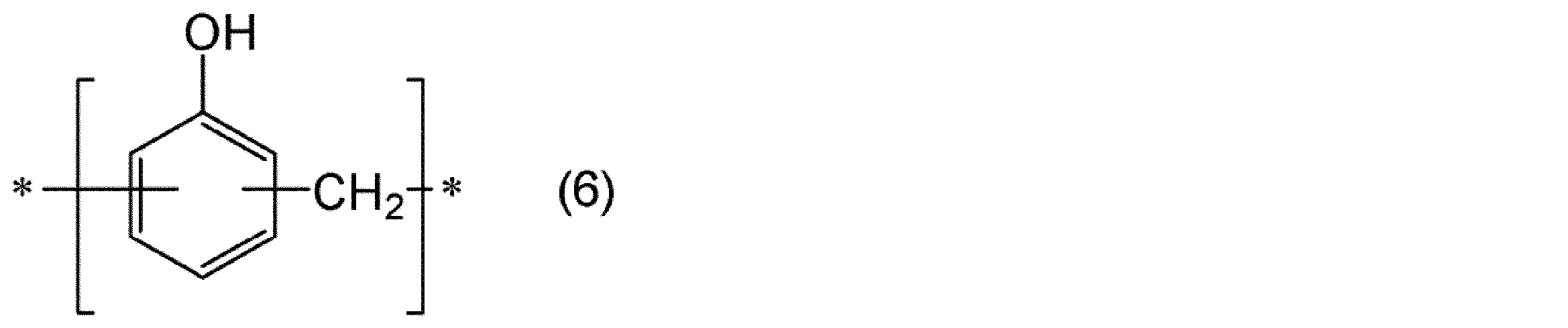
まず、カルダノールと、メタノールと、50%ホルムアルデヒド水溶液とを混合して、混合液を得た。次いで、得られた混合液に30%水酸化ナトリウム水溶液を滴下して反応させた後、得られた反応液に35%塩酸を添加して水酸化ナトリウムを中和した。次いで、反応液にフェノールを添加した後、更にシュウ酸を添加した。次いで、反応液の水洗を行った後、過剰のフェノールを留去した。これにより、下記式(5)で表される構造単位40モル%と、下記式(6)で表される構造単位60モル%とからなる樹脂B1を得た。

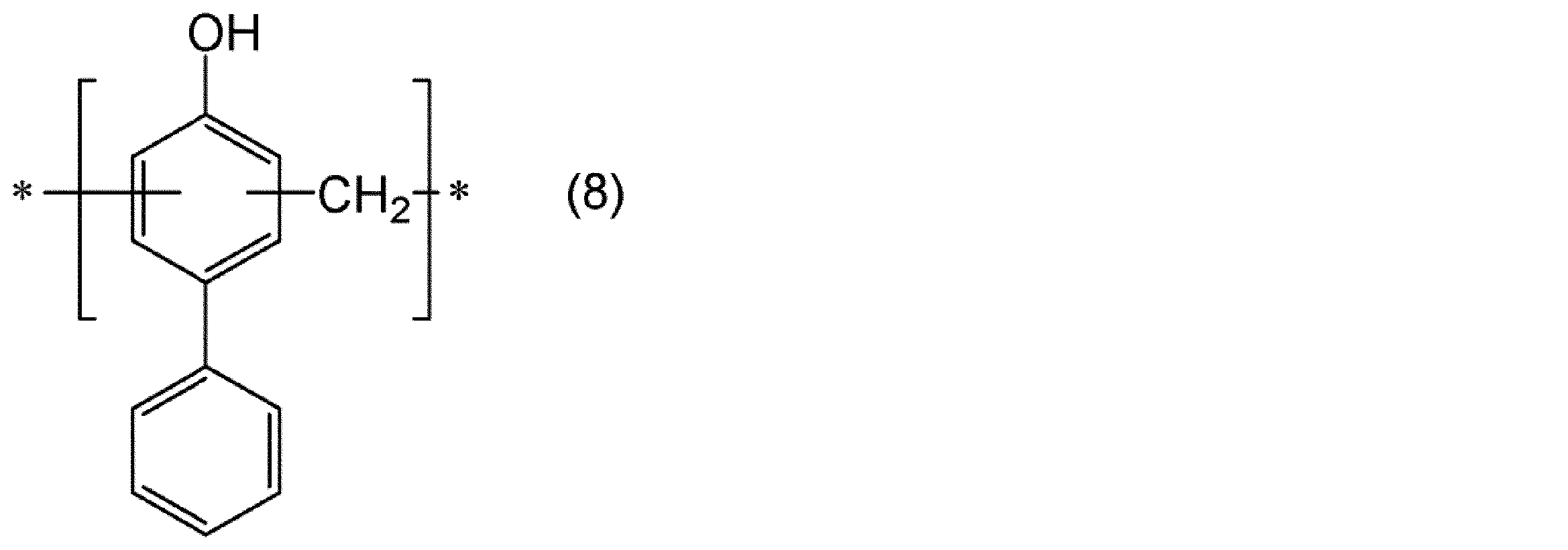
まず、4-tert-ブチルフェノールと、メタノールと、50%ホルムアルデヒド水溶液とを混合して、混合液を得た。次いで、得られた混合液に30%水酸化ナトリウム水溶液を滴下して反応させた後、得られた反応液に35%塩酸を添加して水酸化ナトリウムを中和した。次いで、反応液に4-フェニルフェノールを添加した後、更にシュウ酸を添加した。次いで、反応液の水洗を行った後、過剰の4-フェニルフェノールを留去した。これにより、下記式(7)で表される構造単位50モル%と、下記式(8)で表される構造単位50モル%とからなる樹脂B2を得た。

まず、4-(1,1,3,3-テトラメチルブチル)フェノールと、メタノールと、50%ホルムアルデヒド水溶液とを混合して、混合液を得た。次いで、得られた混合液に30%水酸化ナトリウム水溶液を滴下して反応させた。これにより、下記式(9)で表される構造単位からなる樹脂B3を得た。

まず、カルダノールと、メタノールと、50%ホルムアルデヒド水溶液とを混合して、混合液を得た。次いで、得られた混合液に30%水酸化ナトリウム水溶液を滴下して反応させた後、得られた反応液に35%塩酸を添加して水酸化ナトリウムを中和した。次いで、反応液にペンチルフェノールを添加した後、更にシュウ酸を添加した。次いで、反応液の水洗を行った後、過剰のペンチルフェノールを留去した。これにより、上記式(5)で表される構造単位75モル%と、下記式(10)で表される構造単位25モル%からなる樹脂B4を得た。

(実施例1)
0.5Lのポリエチレン容器に、表1に示す量(質量部)のA1、B1、D1、及びE1を加えて、撹拌羽で撹拌し、無機充填材E1を分散した。その後、表1に示す量(質量部)のC1を加えて、更に30分撹拌した。得られた混合液をナイロン製#150メッシュ(開口106μm)でろ過して、ろ液を採取した。これによりワニス状エポキシ樹脂組成物を得た。このワニス状エポキシ樹脂組成物を、塗工機を使用してPETフィルム上に、以下の条件で塗布した。これにより、厚さ110μmの封止用フィルムを支持体(PETフィルム)上に作製した。
・塗布ヘッド方式:コンマ
・塗布及び乾燥速度:1m/分
・乾燥条件(温度/炉長):80℃/1.5m、100℃/1.5m
・支持体:厚さ38μmのPETフィルム
使用した材料(A1、B1、C1、D1、及びE1)の種類及び配合量を表1に示すように変更したこと以外は、実施例1と同様にして、実施例2~4及び比較例1~2のワニス状エポキシ樹脂組成物を得た。次いで、実施例1のワニス状エポキシ樹脂に代えて、実施例2~4及び比較例1~2のワニス状エポキシ樹脂組成物をそれぞれ用いたこと以外は、実施例1と同様にして、実施例2~4及び比較例1~2の封止用フィルム(厚さ110μm)を得た。
以下の方法で、封止用フィルムの溶融粘度、埋め込み性及び中空非充填性、並びに、封止用フィルムの硬化後の弾性率及びガラス転移温度の評価を行った。
封止用フィルム0.6gを量り取り、圧縮成型機にて直径2cmのタブレット状に成形した。得られた成形物を評価用サンプルとし、以下の条件にて、封止用フィルムの溶融粘度を測定した。測定は、温度を40℃から200℃まで昇温することにより行った。
測定装置:レオメータ製品名:TAインスツルメントジャパン株式会社製ARES-G2
測定モード:Dynamic Temperature Ramp
周波数:1.0Hz
温度範囲:40℃~200℃
昇温速度:5℃/分
以下の方法で、封止温度70℃における封止用フィルムの埋め込み性及び中空非充填性を評価した。まず、主面の中央に貫通孔(直径1mm)を設けた基板(5cm×5cm)を用意した。次いで、当該基板の一方の主面上における上記貫通孔の縁から2cm離れた位置に両面テープを張り付け、両面テープを介して基板上にガラス板を貼り付けた。得られた積層体を、ガラス板側の面を下にして配置し、基板のガラス板とは反対側の面上に、貫通孔を塞ぐように、1cm角サイズの封止用フィルムを配置した。次いで、封止フィルム上に100gの重りを載せた後70℃のオーブン(エスペック株式会社製、商品名「SAFETY OVEN SPH-201」)内で1時間加熱した。
[埋め込み性]
A:ガラス基板まで樹脂が到達
B:ガラス基板まで樹脂が未到達
[中空非充填性]
A:流れ込み面積≦2.5mm2
B:流れ込み面積≦5mm2、>2.5mm2
C:流れ込み面積>5mm2
評価Aの溶融粘度の測定結果に基づき、封止用フィルムの溶融粘度が7000Pa・sとなる温度で封止を行ったこと以外は、評価Bと同様の方法で埋め込み性及び中空非充填性を評価した。
以下の条件で、実施例及び比較例の封止用フィルムを銅箔にラミネートし、銅箔付き封止用フィルムを得た。
・ラミネータ装置:名機製作所製真空加圧ラミネータMVLP-500
・ラミネート温度:110℃
・ラミネート圧力:0.5MPa
・真空引き時間:30秒
・ラミネート時間:40秒
・オーブン:エスペック株式会社製SAFETY OVEN SPH-201
・オーブン温度:140℃
・時間:120分
・測定装置:DVE(株式会社レオロジ製DVE-V4)
・測定温度:25~300℃
・昇温速度:5℃/min
A:弾性率(30℃)≦15GPa
B:弾性率(30℃)>15GPa
A:ガラス転移温度(℃)≧100
B:ガラス転移温度(℃)<100
結果を表1に示す。なお、表1中の各成分の配合量は、固形分量(溶剤の量を除いた量)である。

Claims (12)
- 下記式(1)で表される構造単位を有する熱硬化性樹脂と、無機充填材と、を含有する樹脂組成物からなる、封止用フィルム。

- 前記熱硬化性樹脂は、下記式(2)で表される構造単位を更に有する、請求項1に記載の封止用フィルム。

- 前記X1は水酸基である、請求項1又は2に記載の封止用フィルム。
- 前記樹脂組成物はエポキシ樹脂を更に含有する、請求項1~3のいずれか一項に記載の封止用フィルム。
- 前記熱硬化性樹脂における前記式(1)で表される構造単位の含有量は、前記熱硬化性樹脂を構成する構造単位の全量を基準として、20モル%以上である、請求項1~4のいずれか一項に記載の封止用フィルム。
- 前記熱硬化性樹脂の重量平均分子量は500以上である、請求項1~5のいずれか一項に記載の封止用フィルム。
- 膜厚は20~250μmである、請求項1~6のいずれか一項に記載の封止用フィルム。
- 基板上にバンプを介して設けられた被封止体を封止するために用いられる、請求項1~7のいずれか一項に記載の封止用フィルム。
- 基板と、当該基板上にバンプを介して設けられた被封止体と、を備え、前記基板と前記被封止体との間に中空領域が設けられている、中空構造体を用意し、
請求項1~8のいずれか一項に記載の封止用フィルムにより前記被封止体を封止する、封止構造体の製造方法。 - 前記被封止体は、前記中空領域側に電極を有するSAWデバイスである、請求項9に記載の封止構造体の製造方法。
- 基板と、当該基板上にバンプを介して設けられた被封止体と、当該被封止体を封止する請求項1~8のいずれか一項に記載の封止用フィルムの硬化物と、を備え、
前記基板と前記被封止体との間に中空領域が設けられている、封止構造体。 - 前記被封止体は、前記中空領域側に電極を有するSAWデバイスである、請求項11に記載の封止構造体。
Priority Applications (4)
| Application Number | Priority Date | Filing Date | Title |
|---|---|---|---|
| SG11201908955U SG11201908955UA (en) | 2017-04-28 | 2018-04-27 | Sealing film, sealed structure, and method for manufacturing sealed structure |
| KR1020197025004A KR102505321B1 (ko) | 2017-04-28 | 2018-04-27 | 봉지용 필름, 봉지 구조체 및 봉지 구조체의 제조 방법 |
| JP2019514667A JP7099453B2 (ja) | 2017-04-28 | 2018-04-27 | 封止用フィルム、封止構造体及び封止構造体の製造方法 |
| CN201880027734.5A CN110546184B (zh) | 2017-04-28 | 2018-04-27 | 密封用膜、密封结构体和密封结构体的制造方法 |
Applications Claiming Priority (2)
| Application Number | Priority Date | Filing Date | Title |
|---|---|---|---|
| JP2017-090351 | 2017-04-28 | ||
| JP2017090351 | 2017-04-28 |
Publications (1)
| Publication Number | Publication Date |
|---|---|
| WO2018199306A1 true WO2018199306A1 (ja) | 2018-11-01 |
Family
ID=63919832
Family Applications (1)
| Application Number | Title | Priority Date | Filing Date |
|---|---|---|---|
| PCT/JP2018/017256 Ceased WO2018199306A1 (ja) | 2017-04-28 | 2018-04-27 | 封止用フィルム、封止構造体及び封止構造体の製造方法 |
Country Status (6)
| Country | Link |
|---|---|
| JP (1) | JP7099453B2 (ja) |
| KR (1) | KR102505321B1 (ja) |
| CN (1) | CN110546184B (ja) |
| SG (1) | SG11201908955UA (ja) |
| TW (1) | TWI752222B (ja) |
| WO (1) | WO2018199306A1 (ja) |
Cited By (3)
| Publication number | Priority date | Publication date | Assignee | Title |
|---|---|---|---|---|
| WO2021241680A1 (ja) * | 2020-05-27 | 2021-12-02 | 国立大学法人 東京大学 | 熱硬化性樹脂の超薄膜 |
| WO2022202427A1 (ja) * | 2021-03-24 | 2022-09-29 | 太陽インキ製造株式会社 | 熱硬化性樹脂組成物、ドライフィルム、硬化物、プリント配線板および電気電子部品 |
| JP2024075484A (ja) * | 2022-11-22 | 2024-06-03 | 味の素株式会社 | 樹脂組成物 |
Citations (5)
| Publication number | Priority date | Publication date | Assignee | Title |
|---|---|---|---|---|
| JPH06322348A (ja) * | 1993-05-14 | 1994-11-22 | Toray Ind Inc | フレキシブルプリント基板用接着剤組成物、これを用いたフレキシブルプリント基板およびtab用接着剤付きテープ |
| JP2012182407A (ja) * | 2011-03-03 | 2012-09-20 | Bridgestone Corp | 太陽電池用封止膜及びこれを用いた太陽電池 |
| JP2013082785A (ja) * | 2011-10-07 | 2013-05-09 | Nippon Kayaku Co Ltd | フェノール樹脂、エポキシ樹脂及びその硬化物 |
| JP2015089940A (ja) * | 2013-11-07 | 2015-05-11 | 群栄化学工業株式会社 | 多価ヒドロキシ樹脂、その製造方法、エポキシ樹脂用硬化剤、エポキシ樹脂組成物、硬化物 |
| WO2016052290A1 (ja) * | 2014-10-01 | 2016-04-07 | Dic株式会社 | エポキシ樹脂組成物及びその硬化物 |
Family Cites Families (4)
| Publication number | Priority date | Publication date | Assignee | Title |
|---|---|---|---|---|
| JP4404450B2 (ja) | 2000-06-30 | 2010-01-27 | 京セラ株式会社 | 弾性表面波装置及びその製造方法 |
| JP4989402B2 (ja) | 2007-10-04 | 2012-08-01 | 日東電工株式会社 | 中空型デバイス封止用樹脂組成物シートおよびそれを用いて封止した中空型デバイス |
| JP5725016B2 (ja) * | 2010-03-25 | 2015-05-27 | 住友ベークライト株式会社 | 半導体封止用エポキシ樹脂組成物およびこれを用いた半導体装置 |
| JP6883937B2 (ja) | 2015-03-19 | 2021-06-09 | 日東電工株式会社 | 封止用シートおよび中空パッケージの製造方法 |
-
2018
- 2018-04-27 KR KR1020197025004A patent/KR102505321B1/ko active Active
- 2018-04-27 WO PCT/JP2018/017256 patent/WO2018199306A1/ja not_active Ceased
- 2018-04-27 JP JP2019514667A patent/JP7099453B2/ja active Active
- 2018-04-27 CN CN201880027734.5A patent/CN110546184B/zh active Active
- 2018-04-27 TW TW107114497A patent/TWI752222B/zh active
- 2018-04-27 SG SG11201908955U patent/SG11201908955UA/en unknown
Patent Citations (5)
| Publication number | Priority date | Publication date | Assignee | Title |
|---|---|---|---|---|
| JPH06322348A (ja) * | 1993-05-14 | 1994-11-22 | Toray Ind Inc | フレキシブルプリント基板用接着剤組成物、これを用いたフレキシブルプリント基板およびtab用接着剤付きテープ |
| JP2012182407A (ja) * | 2011-03-03 | 2012-09-20 | Bridgestone Corp | 太陽電池用封止膜及びこれを用いた太陽電池 |
| JP2013082785A (ja) * | 2011-10-07 | 2013-05-09 | Nippon Kayaku Co Ltd | フェノール樹脂、エポキシ樹脂及びその硬化物 |
| JP2015089940A (ja) * | 2013-11-07 | 2015-05-11 | 群栄化学工業株式会社 | 多価ヒドロキシ樹脂、その製造方法、エポキシ樹脂用硬化剤、エポキシ樹脂組成物、硬化物 |
| WO2016052290A1 (ja) * | 2014-10-01 | 2016-04-07 | Dic株式会社 | エポキシ樹脂組成物及びその硬化物 |
Cited By (6)
| Publication number | Priority date | Publication date | Assignee | Title |
|---|---|---|---|---|
| WO2021241680A1 (ja) * | 2020-05-27 | 2021-12-02 | 国立大学法人 東京大学 | 熱硬化性樹脂の超薄膜 |
| JPWO2021241680A1 (ja) * | 2020-05-27 | 2021-12-02 | ||
| JP7473993B2 (ja) | 2020-05-27 | 2024-04-24 | 国立大学法人 東京大学 | 熱硬化性樹脂の超薄膜 |
| WO2022202427A1 (ja) * | 2021-03-24 | 2022-09-29 | 太陽インキ製造株式会社 | 熱硬化性樹脂組成物、ドライフィルム、硬化物、プリント配線板および電気電子部品 |
| JP2024075484A (ja) * | 2022-11-22 | 2024-06-03 | 味の素株式会社 | 樹脂組成物 |
| JP7639869B2 (ja) | 2022-11-22 | 2025-03-05 | 味の素株式会社 | 樹脂組成物 |
Also Published As
| Publication number | Publication date |
|---|---|
| CN110546184B (zh) | 2022-08-26 |
| TW201843288A (zh) | 2018-12-16 |
| TWI752222B (zh) | 2022-01-11 |
| CN110546184A (zh) | 2019-12-06 |
| JP7099453B2 (ja) | 2022-07-12 |
| SG11201908955UA (en) | 2019-11-28 |
| JPWO2018199306A1 (ja) | 2020-03-12 |
| KR20190139197A (ko) | 2019-12-17 |
| KR102505321B1 (ko) | 2023-03-06 |
Similar Documents
| Publication | Publication Date | Title |
|---|---|---|
| JP6763391B2 (ja) | 樹脂組成物、硬化物、封止用フィルム及び封止構造体 | |
| TWI650375B (zh) | 樹脂組成物、樹脂薄膜及半導體裝置與其製造方法 | |
| JP6754741B2 (ja) | 半導体積層体、半導体積層体の製造方法及び半導体装置の製造方法 | |
| JP7099453B2 (ja) | 封止用フィルム、封止構造体及び封止構造体の製造方法 | |
| JP6800115B2 (ja) | 樹脂組成物、樹脂フィルム、半導体積層体、半導体積層体の製造方法及び半導体装置の製造方法 | |
| JP7124819B2 (ja) | 封止用フィルム、封止構造体及び封止構造体の製造方法 | |
| JP7070559B2 (ja) | 封止用フィルム及び封止構造体、並びにこれらの製造方法 | |
| JP7222955B2 (ja) | 樹脂組成物及び樹脂フィルム | |
| CN109983052B (zh) | 密封用膜及其固化物、以及电子装置 | |
| JP6544427B2 (ja) | 熱硬化性樹脂組成物、硬化物、樹脂シート、封止構造体及びその製造方法、並びに、電子部品装置及びその製造方法 | |
| US10308787B2 (en) | Resin composition, resin film, method for producing resin film, method for producing semiconductor device, and semiconductor device |
Legal Events
| Date | Code | Title | Description |
|---|---|---|---|
| 121 | Ep: the epo has been informed by wipo that ep was designated in this application |
Ref document number: 18791706 Country of ref document: EP Kind code of ref document: A1 |
|
| ENP | Entry into the national phase |
Ref document number: 2019514667 Country of ref document: JP Kind code of ref document: A |
|
| ENP | Entry into the national phase |
Ref document number: 20197025004 Country of ref document: KR Kind code of ref document: A |
|
| NENP | Non-entry into the national phase |
Ref country code: DE |
|
| 122 | Ep: pct application non-entry in european phase |
Ref document number: 18791706 Country of ref document: EP Kind code of ref document: A1 |