WO2018199164A1 - 空気浄化システム - Google Patents
空気浄化システム Download PDFInfo
- Publication number
- WO2018199164A1 WO2018199164A1 PCT/JP2018/016795 JP2018016795W WO2018199164A1 WO 2018199164 A1 WO2018199164 A1 WO 2018199164A1 JP 2018016795 W JP2018016795 W JP 2018016795W WO 2018199164 A1 WO2018199164 A1 WO 2018199164A1
- Authority
- WO
- WIPO (PCT)
- Prior art keywords
- air
- room
- carbon dioxide
- space
- purification system
- Prior art date
- Legal status (The legal status is an assumption and is not a legal conclusion. Google has not performed a legal analysis and makes no representation as to the accuracy of the status listed.)
- Ceased
Links
Images

Classifications
-
- B—PERFORMING OPERATIONS; TRANSPORTING
- B01—PHYSICAL OR CHEMICAL PROCESSES OR APPARATUS IN GENERAL
- B01D—SEPARATION
- B01D53/00—Separation of gases or vapours; Recovering vapours of volatile solvents from gases; Chemical or biological purification of waste gases, e.g. engine exhaust gases, smoke, fumes, flue gases, aerosols
- B01D53/22—Separation of gases or vapours; Recovering vapours of volatile solvents from gases; Chemical or biological purification of waste gases, e.g. engine exhaust gases, smoke, fumes, flue gases, aerosols by diffusion
-
- F—MECHANICAL ENGINEERING; LIGHTING; HEATING; WEAPONS; BLASTING
- F24—HEATING; RANGES; VENTILATING
- F24F—AIR-CONDITIONING; AIR-HUMIDIFICATION; VENTILATION; USE OF AIR CURRENTS FOR SCREENING
- F24F3/00—Air-conditioning systems in which conditioned primary air is supplied from one or more central stations to distributing units in the rooms or spaces where it may receive secondary treatment; Apparatus specially designed for such systems
- F24F3/12—Air-conditioning systems in which conditioned primary air is supplied from one or more central stations to distributing units in the rooms or spaces where it may receive secondary treatment; Apparatus specially designed for such systems characterised by the treatment of the air otherwise than by heating and cooling
- F24F3/14—Air-conditioning systems in which conditioned primary air is supplied from one or more central stations to distributing units in the rooms or spaces where it may receive secondary treatment; Apparatus specially designed for such systems characterised by the treatment of the air otherwise than by heating and cooling by humidification; by dehumidification
- F24F3/147—Air-conditioning systems in which conditioned primary air is supplied from one or more central stations to distributing units in the rooms or spaces where it may receive secondary treatment; Apparatus specially designed for such systems characterised by the treatment of the air otherwise than by heating and cooling by humidification; by dehumidification with both heat and humidity transfer between supplied and exhausted air
-
- F—MECHANICAL ENGINEERING; LIGHTING; HEATING; WEAPONS; BLASTING
- F24—HEATING; RANGES; VENTILATING
- F24F—AIR-CONDITIONING; AIR-HUMIDIFICATION; VENTILATION; USE OF AIR CURRENTS FOR SCREENING
- F24F7/00—Ventilation
- F24F7/003—Ventilation in combination with air cleaning
-
- F—MECHANICAL ENGINEERING; LIGHTING; HEATING; WEAPONS; BLASTING
- F24—HEATING; RANGES; VENTILATING
- F24F—AIR-CONDITIONING; AIR-HUMIDIFICATION; VENTILATION; USE OF AIR CURRENTS FOR SCREENING
- F24F7/00—Ventilation
- F24F7/04—Ventilation with ducting systems, e.g. by double walls; with natural circulation
- F24F7/06—Ventilation with ducting systems, e.g. by double walls; with natural circulation with forced air circulation, e.g. by fan positioning of a ventilator in or against a conduit
- F24F7/08—Ventilation with ducting systems, e.g. by double walls; with natural circulation with forced air circulation, e.g. by fan positioning of a ventilator in or against a conduit with separate ducts for supplied and exhausted air with provisions for reversal of the input and output systems
-
- B—PERFORMING OPERATIONS; TRANSPORTING
- B01—PHYSICAL OR CHEMICAL PROCESSES OR APPARATUS IN GENERAL
- B01D—SEPARATION
- B01D53/00—Separation of gases or vapours; Recovering vapours of volatile solvents from gases; Chemical or biological purification of waste gases, e.g. engine exhaust gases, smoke, fumes, flue gases, aerosols
- B01D53/22—Separation of gases or vapours; Recovering vapours of volatile solvents from gases; Chemical or biological purification of waste gases, e.g. engine exhaust gases, smoke, fumes, flue gases, aerosols by diffusion
- B01D2053/221—Devices
-
- B—PERFORMING OPERATIONS; TRANSPORTING
- B01—PHYSICAL OR CHEMICAL PROCESSES OR APPARATUS IN GENERAL
- B01D—SEPARATION
- B01D2257/00—Components to be removed
- B01D2257/50—Carbon oxides
- B01D2257/504—Carbon dioxide
-
- B—PERFORMING OPERATIONS; TRANSPORTING
- B01—PHYSICAL OR CHEMICAL PROCESSES OR APPARATUS IN GENERAL
- B01D—SEPARATION
- B01D2258/00—Sources of waste gases
- B01D2258/06—Polluted air
-
- B—PERFORMING OPERATIONS; TRANSPORTING
- B01—PHYSICAL OR CHEMICAL PROCESSES OR APPARATUS IN GENERAL
- B01D—SEPARATION
- B01D2259/00—Type of treatment
- B01D2259/45—Gas separation or purification devices adapted for specific applications
- B01D2259/4508—Gas separation or purification devices adapted for specific applications for cleaning air in buildings
-
- F—MECHANICAL ENGINEERING; LIGHTING; HEATING; WEAPONS; BLASTING
- F24—HEATING; RANGES; VENTILATING
- F24F—AIR-CONDITIONING; AIR-HUMIDIFICATION; VENTILATION; USE OF AIR CURRENTS FOR SCREENING
- F24F3/00—Air-conditioning systems in which conditioned primary air is supplied from one or more central stations to distributing units in the rooms or spaces where it may receive secondary treatment; Apparatus specially designed for such systems
- F24F3/12—Air-conditioning systems in which conditioned primary air is supplied from one or more central stations to distributing units in the rooms or spaces where it may receive secondary treatment; Apparatus specially designed for such systems characterised by the treatment of the air otherwise than by heating and cooling
- F24F3/14—Air-conditioning systems in which conditioned primary air is supplied from one or more central stations to distributing units in the rooms or spaces where it may receive secondary treatment; Apparatus specially designed for such systems characterised by the treatment of the air otherwise than by heating and cooling by humidification; by dehumidification
- F24F2003/1435—Air-conditioning systems in which conditioned primary air is supplied from one or more central stations to distributing units in the rooms or spaces where it may receive secondary treatment; Apparatus specially designed for such systems characterised by the treatment of the air otherwise than by heating and cooling by humidification; by dehumidification comprising semi-permeable membrane
-
- F—MECHANICAL ENGINEERING; LIGHTING; HEATING; WEAPONS; BLASTING
- F24—HEATING; RANGES; VENTILATING
- F24F—AIR-CONDITIONING; AIR-HUMIDIFICATION; VENTILATION; USE OF AIR CURRENTS FOR SCREENING
- F24F2110/00—Control inputs relating to air properties
- F24F2110/50—Air quality properties
- F24F2110/65—Concentration of specific substances or contaminants
- F24F2110/70—Carbon dioxide
-
- Y—GENERAL TAGGING OF NEW TECHNOLOGICAL DEVELOPMENTS; GENERAL TAGGING OF CROSS-SECTIONAL TECHNOLOGIES SPANNING OVER SEVERAL SECTIONS OF THE IPC; TECHNICAL SUBJECTS COVERED BY FORMER USPC CROSS-REFERENCE ART COLLECTIONS [XRACs] AND DIGESTS
- Y02—TECHNOLOGIES OR APPLICATIONS FOR MITIGATION OR ADAPTATION AGAINST CLIMATE CHANGE
- Y02B—CLIMATE CHANGE MITIGATION TECHNOLOGIES RELATED TO BUILDINGS, e.g. HOUSING, HOUSE APPLIANCES OR RELATED END-USER APPLICATIONS
- Y02B30/00—Energy efficient heating, ventilation or air conditioning [HVAC]
- Y02B30/70—Efficient control or regulation technologies, e.g. for control of refrigerant flow, motor or heating
Definitions
- the present invention relates to an air purification system that purifies air in a room.
- Ventilation is carried out for rooms that accommodate people in buildings and transport equipment in order to suppress the increase in carbon dioxide concentration.
- the room is provided with an air conditioner for heating or cooling.
- the ventilation volume for suppressing the above-mentioned increase in carbon dioxide concentration is relatively large, so the load on the air conditioner increases accordingly.
- Patent Document 1 discloses an air purification system mounted on a railway vehicle.
- a carbon dioxide removing device is provided in a circulation path for circulating the air in the room.
- the carbon dioxide removing device includes a separation membrane that selectively permeates carbon dioxide.
- the carbon dioxide removing device has a permeation side in order to give a pressure difference between the circulation path side of the separation membrane (one of the spaces partitioned by the separation membrane) and the permeation side (the other of the spaces partitioned by the separation membrane).
- a vacuum pump for evacuating is connected.
- an object of the present invention is to realize an air purification system that can purify air in a room without using a pump that performs vacuuming.
- an air purification system of the present invention is an air purification system for purifying air in a room, and includes a first space and a second space partitioned by a separation membrane that selectively transmits carbon dioxide.
- a carbon dioxide removing device including a space; a feed path that guides air in the room to the first space; a return path that guides clean air from which carbon dioxide has been removed from the first space to the room;
- a pressure difference is generated in the partial pressure of carbon dioxide between the first space and the second space partitioned by the separation membrane.
- the carbon dioxide in the air led to the first space selectively permeates the separation membrane. Therefore, the air in the room can be purified without using a pump that performs evacuation.
- the sweep gas may be outside air.
- the air purification system includes an air conditioner for heating and cooling provided in the room, the first ventilation path for supplying outside air to the room, and the second ventilation path for exhausting air in the room. And a heat exchanger that performs sensible heat exchange between the air flowing through the second ventilation path and the sweep gas flowing through the supply path. According to this configuration, since the temperature of the sweep gas supplied to the second space can be brought close to the temperature of the air in the room by sensible heat exchange in the heat exchanger, sensible heat exchange via the separation membrane can be performed. Can be suppressed.
- the heat exchanger may perform not only sensible heat exchange but also latent heat exchange. According to this configuration, when the separation membrane allows not only carbon dioxide but also water vapor to pass therethrough, it is possible to prevent the humidity of the air in the room from changing before and after the removal of carbon dioxide.
- the supply path may be branched from the return path, and the sweep gas may be clean air. According to this configuration, a part of the clean air flowing out from the carbon dioxide removing device is used as the sweep gas, so that the configuration can be simplified.
- the air in the room can be purified without using a pump that performs evacuation.
- FIG. 1 is a schematic configuration diagram of an air purification system according to a first embodiment of the present invention. It is a schematic block diagram of the air purification system which concerns on 2nd Embodiment of this invention. It is a schematic block diagram of the air purification system which concerns on 3rd Embodiment of this invention.
- FIG. 1 shows an air purification system 1A according to the first embodiment of the present invention.
- This air purification system 1A purifies the air in the room 2 that accommodates people.
- the room 2 may be a room of a building such as an office building, or may be a room of transportation equipment such as a railway vehicle or an aircraft (so-called cabin).
- the room 2 may be a space station, a submarine, a disaster evacuation facility, or the like.
- the air purification system 1A includes a carbon dioxide removing device 4.
- the carbon dioxide removing device 4 is arranged outside the room 2, but the carbon dioxide removing device 4 may be arranged inside the room 2.
- the carbon dioxide removing device 4 includes a first space 41 and a second space 42 partitioned by a separation membrane 43.
- the separation membrane 43 selectively transmits carbon dioxide from the first space 41 toward the second space 42.
- the separation membrane 43 is a hollow fiber membrane.
- many hollow fiber membranes may comprise one membrane module, and the carbon dioxide removal apparatus 4 may contain many membrane modules.
- the separation membrane 43 is a hollow fiber membrane, the inside of the hollow fiber membrane is the first space 41 and the outside of the hollow fiber membrane is the second space 42.
- Air in the room 2 is guided to the first space 41 of the carbon dioxide removal device 4 through the feed path 51, and clean air from which carbon dioxide has been removed is guided to the room 2 through the return path 52 from the first space 41. It is burned.
- the blower 53 is provided in the feed path 51, but the blower 53 may be provided in the return path 52.
- the blower 53 may be a blower or a fan (the same applies to a blower described later).
- the sweep gas is guided to the second space 42 of the carbon dioxide removal device 4 through the supply path 61.
- the sweep gas has a lower partial pressure of carbon dioxide than the air in the room 2.
- the sweep gas is the outside air that is the atmosphere outside the room 2. That is, the upstream end of the supply path 61 is open to the atmosphere.
- the partial pressure of carbon dioxide is about 0.1 kPa.
- the carbon dioxide partial pressure is about 0.04 kPa.
- the sweep gas mixed with carbon dioxide that has permeated through the separation membrane 43 is discharged from the second space 42 to the atmosphere through the discharge path 62. That is, the downstream end of the discharge path 62 is open to the atmosphere.
- the blower 63 is provided in the supply path 61, but the blower 63 may be provided in the discharge path 62.
- the room 2 is provided with an air conditioner 3 for heating and cooling.
- the room 2 is connected to a first ventilation path 71 and a second ventilation path 72.
- Blowers 73 and 74 are provided in the first ventilation path 71 and the second ventilation path 72, respectively.
- a pressure difference occurs in the partial pressure of carbon dioxide between the first space 41 and the second space 42 partitioned by the separation membrane 43.
- carbon dioxide in the air guided to the first space 41 selectively permeates the separation membrane 43. Therefore, the air in the room 2 can be purified without using a pump that performs evacuation.
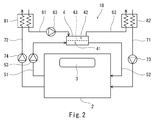
- FIG. 2 shows an air purification system 1B according to the second embodiment of the present invention.
- the same components as those in the first embodiment are denoted by the same reference numerals, and redundant description is omitted.
- the air purification system 1B of the present embodiment is obtained by adding a first heat exchanger 81 and a second heat exchanger 82 to the air purification system 1A of the first embodiment.
- the first heat exchanger 81 performs sensible heat exchange between the air flowing through the second ventilation path 72 and the sweep gas (outside air) flowing through the supply path 61.
- the second heat exchanger 82 performs sensible heat exchange between the outside air flowing through the first ventilation path 71 and the sweep gas flowing through the discharge path 62.
- the same effect as in the first embodiment can be obtained.
- the temperature of the sweep gas supplied to the second space 42 can be brought close to the temperature of the air in the room 2 by sensible heat exchange in the first heat exchanger 81, and thus the separation membrane 43.
- the sensible heat exchange via can be suppressed.
- the outside air supplied to the room 2 through the first ventilation path 71 can be heated or cooled in advance by sensible heat exchange in the second heat exchanger 82.
- the first heat exchanger 81 desirably performs not only sensible heat exchange but also latent heat exchange.
- the separation membrane 43 allows not only carbon dioxide but also water vapor to pass therethrough, it is possible to prevent the humidity of the air in the room 2 from changing before and after the removal of carbon dioxide.
- latent heat exchange is movement of water vapor from a high humidity side to a low humidity side.
- the first heat exchanger 81 may be a total heat exchanger or a combination of a latent heat exchange membrane (water vapor permeable membrane) and a sensible heat exchanger.
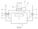
- FIG. 3 shows an air purification system 1C according to a third embodiment of the present invention.
- the upstream end of the supply path 61 is not open to the atmosphere but is connected to the return path 52. That is, the supply path 61 branches from the return path 52, and the sweep gas is clean air from which carbon dioxide has been removed.
- the present invention is not limited to the above-described embodiments, and various modifications can be made without departing from the gist of the present invention.
- the air conditioner 3 is not necessarily provided in the room 2.
Landscapes
- Engineering & Computer Science (AREA)
- Chemical & Material Sciences (AREA)
- Combustion & Propulsion (AREA)
- Mechanical Engineering (AREA)
- General Engineering & Computer Science (AREA)
- Analytical Chemistry (AREA)
- General Chemical & Material Sciences (AREA)
- Oil, Petroleum & Natural Gas (AREA)
- Chemical Kinetics & Catalysis (AREA)
- Separation Using Semi-Permeable Membranes (AREA)
- Central Air Conditioning (AREA)
Abstract
空気浄化システムは、部屋内の空気を浄化する空気浄化システムであって、二酸化炭素を選択的に透過させる分離膜で仕切られた第1空間および第2空間を含む二酸化炭素除去装置と、部屋内の空気を第1空間へ導く送り路と、二酸化炭素が除去された清浄空気を第1空間から部屋へ導く戻り路と、部屋内の空気よりも二酸化炭素分圧の低いスイープガスを第2空間へ供給する供給路と、分離膜を透過した二酸化炭素と混合したスイープガスを第2空間から排出する排出路と、を備える。
Description
本発明は、部屋内の空気を浄化する空気浄化システムに関する。
建物や輸送機器などにおける人を収容する部屋に対しては、二酸化炭素濃度の上昇を抑えるために換気が行われる。また、部屋には、暖房または冷房を行う空調装置が設けられる。
上記の二酸化炭素濃度の上昇を抑えるための換気量は比較的に大きいために、その分、空調装置の負荷が高くなる。近年では、空調装置の負荷を低減するために、部屋内の空気から二酸化炭素を除去して当該空気を浄化することが提案されている。
例えば、特許文献1には、鉄道車両に搭載される空気浄化システムが開示されている。この空気浄化システムでは、部屋内の空気を循環させる循環路に二酸化炭素除去装置が設けられている。二酸化炭素除去装置は、二酸化炭素を選択的に透過させる分離膜を含む。また、二酸化炭素除去装置には、分離膜の循環路側(分離膜で仕切られる空間の一方)と透過側(分離膜で仕切られる空間の他方)との間に圧力差を与えるために、透過側を真空引きする減圧ポンプが接続されている。
しかしながら、真空引きを行うポンプを用いた場合には、そのポンプの駆動に比較的に大きな電力を要する。
そこで、本発明は、真空引きを行うポンプを用いずに部屋内の空気を浄化することができる空気浄化システムを実現することを目的とする。
前記課題を解決するために、本発明の空気浄化システムは、部屋内の空気を浄化する空気浄化システムであって、二酸化炭素を選択的に透過させる分離膜で仕切られた第1空間および第2空間を含む二酸化炭素除去装置と、前記部屋内の空気を前記第1空間へ導く送り路と、二酸化炭素が除去された清浄空気を前記第1空間から前記部屋へ導く戻り路と、前記部屋内の空気よりも二酸化炭素分圧の低いスイープガスを前記第2空間へ供給する供給路と、前記分離膜を透過した二酸化炭素と混合した前記スイープガスを前記第2空間から排出する排出路と、を備える、ことを特徴とする。
上記の構成によれば、分離膜で仕切られた第1空間と第2空間との間で二酸化炭素分圧に圧力差が生じる。これにより、第1空間に導かれた空気中の二酸化炭素が分離膜を選択的に透過する。従って、真空引きを行うポンプを用いずに部屋内の空気を浄化することができる。
例えば、前記スイープガスは、外気であってもよい。
上記の空気浄化システムは、前記部屋に設けられた、暖房および冷房を行う空調装置と、前記部屋へ外気を供給する前記第1換気路と、前記部屋内の空気を排出する第2換気路と、前記第2換気路を流れる空気と前記供給路を流れるスイープガスとの間で顕熱交換を行う熱交換器と、をさらに備えてもよい。この構成によれば、熱交換器での顕熱交換により、第2空間へ供給されるスイープガスの温度を部屋内の空気の温度に近づけることができるため、分離膜を介した顕熱交換を抑制することができる。
前記熱交換器は、顕熱交換だけでなく潜熱交換をも行うものであってもよい。この構成によれば、分離膜が二酸化炭素だけでなく水蒸気をも透過させるものである場合に、二酸化炭素の除去の前後で部屋内の空気の湿度が変化することを抑制することができる。
前記供給路は、前記戻り路から分岐しており、前記スイープガスは、清浄空気であってもよい。この構成によれば、二酸化炭素除去装置から流出する清浄空気の一部がスイープガスとして利用されるため、構成を簡易化することができる。
本発明によれば、真空引きを行うポンプを用いずに部屋内の空気を浄化することができる。
(第1実施形態)
図1に、本発明の第1実施形態に係る空気浄化システム1Aを示す。この空気浄化システム1Aは、人を収容する部屋2内の空気を浄化するものである。
図1に、本発明の第1実施形態に係る空気浄化システム1Aを示す。この空気浄化システム1Aは、人を収容する部屋2内の空気を浄化するものである。
例えば、部屋2は、オフィスビルのような建物の部屋であってもよいし、鉄道車両や航空機のような輸送機器の部屋(いわゆるキャビン)であってもよい。あるいは、部屋2は、宇宙ステーション、潜水船、災害時避難設備などの部屋であってもよい。
空気浄化システム1Aは、二酸化炭素除去装置4を含む。図例では、二酸化炭素除去装置4が部屋2外に配置されているが、二酸化炭素除去装置4は部屋2内に配置されてもよい。
二酸化炭素除去装置4は、分離膜43で仕切られた第1空間41および第2空間42を含む。分離膜43は、第1空間41から第2空間42へ向かって、二酸化炭素を選択的に透過させる。
例えば、分離膜43は、中空糸膜である。この場合、多数の中空糸膜が1つの膜モジュールを構成し、二酸化炭素除去装置4が多数の膜モジュールを含んでもよい。分離膜43が中空糸膜である場合、中空糸膜の内側が第1空間41、中空糸膜の外側が第2空間42である。
二酸化炭素除去装置4の第1空間41へは、送り路51を通じて部屋2内の空気が導かれ、第1空間41からは、戻り路52を通じて二酸化炭素が除去された清浄空気が部屋2へ導かれる。本実施形態では、送り路51に送風機53が設けられているが、送風機53は戻り路52に設けられてもよい。送風機53は、ブロアであってもよいしファンであってもよい(後述する送風機も同様)。
二酸化炭素除去装置4の第2空間42へは、供給路61を通じてスイープガスが導かれる。スイープガスは、部屋2内の空気よりも二酸化炭素分圧の低いものである。本実施形態では、スイープガスが、部屋2外の大気である外気である。つまり、供給路61の上流端は、大気中に開口している。
例えば、部屋2内の空気中の二酸化炭素濃度が1000ppmである場合、その二酸化炭素分圧は約0.1kPaである。一方、外気中の二酸化炭素濃度が400ppmである場合、その二酸化炭素分圧は約0.04kPaである。
二酸化炭素除去装置4の第2空間42内で、分離膜43を透過した二酸化炭素と混合したスイーブガスは、排出路62を通じて第2空間42から大気中へ排出される。つまり、排出路62の下流端は、大気中に開口している。
本実施形態では、供給路61に送風機63が設けられているが、送風機63は排出路62に設けられてもよい。
部屋2には、暖房および冷房を行う空調装置3が設けられている。また、部屋2には、第1換気路71および第2換気路72が接続されている。
部屋2へは、第1換気路71を通じて大気中から外気が供給され、部屋2内の空気は、第2換気路72を通じて大気中へ排出される。第1換気路71および第2換気路72には、それぞれ送風機73,74が設けられている。
以上説明したように、本実施形態の空気浄化システム1Aでは、分離膜43で仕切られた第1空間41と第2空間42との間で二酸化炭素分圧に圧力差が生じる。これにより、第1空間41に導かれた空気中の二酸化炭素が分離膜43を選択的に透過する。従って、真空引きを行うポンプを用いずに部屋2内の空気を浄化することができる。
(第2実施形態)
図2に、本発明の第2実施形態に係る空気浄化システム1Bを示す。なお、本実施形態および後述する第3実施形態において、第1実施形態と同一構成要素には同一符号を付し、重複した説明は省略する。
図2に、本発明の第2実施形態に係る空気浄化システム1Bを示す。なお、本実施形態および後述する第3実施形態において、第1実施形態と同一構成要素には同一符号を付し、重複した説明は省略する。
本実施形態の空気浄化システム1Bは、第1実施形態の空気浄化システム1Aに第1熱交換器81と第2熱交換器82を加えたものである。
第1熱交換器81は、第2換気路72を流れる空気と供給路61を流れるスイープガス(外気)との間で顕熱交換を行う。第2熱交換器82は、第1換気路71を流れる外気と排出路62を流れるスイーブガスとの間で顕熱交換を行う。
本実施形態でも、第1実施形態と同様の効果を得ることができる。さらに、本実施形態では、第1熱交換器81での顕熱交換により、第2空間42へ供給されるスイープガスの温度を部屋2内の空気の温度に近づけることができるため、分離膜43を介した顕熱交換を抑制することができる。また、第2熱交換器82での顕熱交換により、第1換気路71を通じて部屋2へ供給される外気を予め加熱または冷却することができる。
なお、第1熱交換器81は、顕熱交換だけでなく潜熱交換をも行うものであることが望ましい。この場合には、分離膜43が二酸化炭素だけでなく水蒸気をも透過させるものである場合に、二酸化炭素の除去の前後で部屋2内の空気の湿度が変化することを抑制することができる。なお、潜熱交換とは、湿度の高い側から低い側へ水蒸気が移動することである。
例えば、第1熱交換器81は、全熱交換器であってもよいし、潜熱交換膜(水蒸気透過膜)と顕熱交換器の組み合わせであってもよい。
(第3実施形態)
図3に、本発明の第3実施形態に係る空気浄化システム1Cを示す。本実施形態では、供給路61の上流端が大気中に開口しているのではなく、戻り路52に接続されている。つまり、供給路61は戻り路52から分岐しており、スイープガスは、二酸化炭素が除去された清浄空気である。
図3に、本発明の第3実施形態に係る空気浄化システム1Cを示す。本実施形態では、供給路61の上流端が大気中に開口しているのではなく、戻り路52に接続されている。つまり、供給路61は戻り路52から分岐しており、スイープガスは、二酸化炭素が除去された清浄空気である。
本実施形態でも、第1実施形態と同様の効果を得ることができる。さらに、本実施形態では、二酸化炭素除去装置4から流出する清浄空気の一部がスイープガスとして利用されるため、構成を簡易化することができる。
(その他の実施形態)
本発明は上述した実施形態に限定されるものではなく、本発明の要旨を逸脱しない範囲で種々の変形が可能である。例えば、部屋2には、必ずしも空調装置3が設けられている必要はない。
本発明は上述した実施形態に限定されるものではなく、本発明の要旨を逸脱しない範囲で種々の変形が可能である。例えば、部屋2には、必ずしも空調装置3が設けられている必要はない。
1A~1C 空気浄化システム
2 部屋
3 空調装置
4 二酸化炭素除去装置
41 第1空間
42 第2空間
43 分離膜
51 送り路
52 戻り路
61 供給路
62 排出路
71 第1換気路
72 第2換気路
2 部屋
3 空調装置
4 二酸化炭素除去装置
41 第1空間
42 第2空間
43 分離膜
51 送り路
52 戻り路
61 供給路
62 排出路
71 第1換気路
72 第2換気路
Claims (5)
- 部屋内の空気を浄化する空気浄化システムであって、
二酸化炭素を選択的に透過させる分離膜で仕切られた第1空間および第2空間を含む二酸化炭素除去装置と、
前記部屋内の空気を前記第1空間へ導く送り路と、
二酸化炭素が除去された清浄空気を前記第1空間から前記部屋へ導く戻り路と、
前記部屋内の空気よりも二酸化炭素分圧の低いスイープガスを前記第2空間へ供給する供給路と、
前記分離膜を透過した二酸化炭素と混合した前記スイープガスを前記第2空間から排出する排出路と、
を備える、空気浄化システム。 - 前記スイープガスは、外気である、請求項1に記載の空気浄化システム。
- 前記部屋に設けられた、暖房および冷房を行う空調装置と、
前記部屋へ外気を供給する前記第1換気路と、
前記部屋内の空気を排出する第2換気路と、
前記第2換気路を流れる空気と前記供給路を流れるスイープガスとの間で顕熱交換を行う熱交換器と、
をさらに備える、請求項2に記載の空気浄化システム。 - 前記熱交換器は、顕熱交換だけでなく潜熱交換をも行うものである、請求項3に記載の空気浄化システム。
- 前記供給路は、前記戻り路から分岐しており、
前記スイープガスは、清浄空気である、請求項1に記載の空気浄化システム。
Priority Applications (2)
| Application Number | Priority Date | Filing Date | Title |
|---|---|---|---|
| US16/608,885 US11413573B2 (en) | 2017-04-27 | 2018-04-25 | Air purifying system |
| CN201880025138.3A CN110494696B (zh) | 2017-04-27 | 2018-04-25 | 空气净化系统 |
Applications Claiming Priority (2)
| Application Number | Priority Date | Filing Date | Title |
|---|---|---|---|
| JP2017087807A JP6970522B2 (ja) | 2017-04-27 | 2017-04-27 | 空気浄化システム |
| JP2017-087807 | 2017-04-27 |
Publications (1)
| Publication Number | Publication Date |
|---|---|
| WO2018199164A1 true WO2018199164A1 (ja) | 2018-11-01 |
Family
ID=63918415
Family Applications (1)
| Application Number | Title | Priority Date | Filing Date |
|---|---|---|---|
| PCT/JP2018/016795 Ceased WO2018199164A1 (ja) | 2017-04-27 | 2018-04-25 | 空気浄化システム |
Country Status (4)
| Country | Link |
|---|---|
| US (1) | US11413573B2 (ja) |
| JP (1) | JP6970522B2 (ja) |
| CN (1) | CN110494696B (ja) |
| WO (1) | WO2018199164A1 (ja) |
Families Citing this family (5)
| Publication number | Priority date | Publication date | Assignee | Title |
|---|---|---|---|---|
| JP6609386B1 (ja) | 2019-02-05 | 2019-11-20 | 川崎重工業株式会社 | 空気浄化システム |
| JP7773852B2 (ja) * | 2020-11-10 | 2025-11-20 | 日産自動車株式会社 | 車両用空調方法及び車両用空調システム |
| CN114923246A (zh) * | 2022-01-22 | 2022-08-19 | 上海交大高新技术股份有限公司 | 一种建筑内空间节能新风循环系统 |
| JP2024047604A (ja) * | 2022-09-27 | 2024-04-08 | パナソニックIpマネジメント株式会社 | Co2分離システム |
| WO2026059604A1 (en) * | 2024-09-11 | 2026-03-19 | W. L. Gore & Associates, Inc. | Dehumidifying systems and methods |
Citations (4)
| Publication number | Priority date | Publication date | Assignee | Title |
|---|---|---|---|---|
| JPH0361198A (ja) * | 1989-07-29 | 1991-03-15 | Shimadzu Corp | 航空機用空気再生装置 |
| WO2008136215A1 (ja) * | 2007-04-26 | 2008-11-13 | C'stec Corporation | クリーンユニット、クリーンユニットの運転方法および連結クリーンユニット |
| JP2010120496A (ja) * | 2008-11-19 | 2010-06-03 | Denso Corp | 車両用空気清浄装置および車両用空調装置 |
| US20130074688A1 (en) * | 2010-02-02 | 2013-03-28 | Generon Igs, Inc. | Sweep gas for membrane-based dehydration modules |
Family Cites Families (18)
| Publication number | Priority date | Publication date | Assignee | Title |
|---|---|---|---|---|
| JP2800175B2 (ja) * | 1986-07-21 | 1998-09-21 | 株式会社島津製作所 | 航空機用空気調和装置 |
| JP2001239125A (ja) * | 2000-03-01 | 2001-09-04 | Nabco Ltd | 中空糸膜式除湿装置 |
| JP2003025991A (ja) | 2001-07-13 | 2003-01-29 | Hitachi Ltd | 換気装置 |
| JP5039293B2 (ja) | 2005-09-28 | 2012-10-03 | 川崎重工業株式会社 | 炭酸ガス除去設備 |
| US20080011160A1 (en) * | 2006-07-17 | 2008-01-17 | General Electric Company | Carbon dioxide capture systems and methods |
| JP5383146B2 (ja) * | 2007-10-29 | 2014-01-08 | 信越ポリマー株式会社 | 非対称膜及びこれを用いた空調システム |
| JP2011247566A (ja) | 2010-05-31 | 2011-12-08 | Seibu Giken Co Ltd | デシカント空調機 |
| TWI541478B (zh) * | 2009-10-27 | 2016-07-11 | Seibu Giken Kk | Air conditioning unit |
| JP2012032138A (ja) * | 2010-06-30 | 2012-02-16 | Denso Corp | 換気装置 |
| US20140157985A1 (en) * | 2011-05-03 | 2014-06-12 | University Of Mississippi | Dehumidification Systems and Methods Thereof |
| JP5849889B2 (ja) * | 2011-08-02 | 2016-02-03 | 株式会社デンソー | 空調システム |
| US9597632B2 (en) * | 2012-02-06 | 2017-03-21 | Renaissance Energy Research Corporation | Selectively CO 2-permeable membrane, method for separating CO2 from mixed gas, and membrane separation equipment |
| DK2813279T3 (da) * | 2012-02-06 | 2020-08-24 | Renaissance Energy Res Corp | Selektiv co2-permeabel membran, fremgangsmåde til at separere co2 fra blandingsgas, og membranseparationsudstyr |
| CN104379234B (zh) * | 2012-05-22 | 2018-02-27 | 恩沃德系统公司 | 对室内空气的洗涤的吸附剂的高效利用 |
| CN104470618B (zh) * | 2012-07-18 | 2018-07-24 | 恩沃德系统公司 | 用于室内空气洗涤的再生吸附剂 |
| JP6490388B2 (ja) * | 2014-10-21 | 2019-03-27 | 国立大学法人神戸大学 | アミノ酸イオン性液体含有相互侵入網目構造体及びその製造方法 |
| JP6652806B2 (ja) | 2015-10-13 | 2020-02-26 | 清水建設株式会社 | 空調システム |
| JP6555489B2 (ja) * | 2017-04-17 | 2019-08-07 | シーズテック株式会社 | ガス交換装置 |
-
2017
- 2017-04-27 JP JP2017087807A patent/JP6970522B2/ja active Active
-
2018
- 2018-04-25 CN CN201880025138.3A patent/CN110494696B/zh active Active
- 2018-04-25 US US16/608,885 patent/US11413573B2/en active Active
- 2018-04-25 WO PCT/JP2018/016795 patent/WO2018199164A1/ja not_active Ceased
Patent Citations (4)
| Publication number | Priority date | Publication date | Assignee | Title |
|---|---|---|---|---|
| JPH0361198A (ja) * | 1989-07-29 | 1991-03-15 | Shimadzu Corp | 航空機用空気再生装置 |
| WO2008136215A1 (ja) * | 2007-04-26 | 2008-11-13 | C'stec Corporation | クリーンユニット、クリーンユニットの運転方法および連結クリーンユニット |
| JP2010120496A (ja) * | 2008-11-19 | 2010-06-03 | Denso Corp | 車両用空気清浄装置および車両用空調装置 |
| US20130074688A1 (en) * | 2010-02-02 | 2013-03-28 | Generon Igs, Inc. | Sweep gas for membrane-based dehydration modules |
Also Published As
| Publication number | Publication date |
|---|---|
| US11413573B2 (en) | 2022-08-16 |
| JP6970522B2 (ja) | 2021-11-24 |
| US20200086269A1 (en) | 2020-03-19 |
| JP2018185115A (ja) | 2018-11-22 |
| CN110494696B (zh) | 2022-04-29 |
| CN110494696A (zh) | 2019-11-22 |
Similar Documents
| Publication | Publication Date | Title |
|---|---|---|
| WO2018199164A1 (ja) | 空気浄化システム | |
| JP6877229B2 (ja) | 空気浄化システム | |
| EP2782657B1 (en) | Distributed building-integrated carbon dioxide extraction system reducing fresh air requirements | |
| CN100379486C (zh) | 降低空气中二氧化碳浓度的方法和设备 | |
| JP5606946B2 (ja) | パージゾーンのない超低露点温度の乾燥空気を供給するデシカント空調機 | |
| US20140211531A1 (en) | Liquid cooling type power conversion apparatus and railway vehicle | |
| MX2024014574A (es) | Sistema de captura directa de aire con panel movil de alto rendimiento | |
| US20200031501A1 (en) | Systems and methods for air revitalization | |
| JP2018502303A5 (ja) | ||
| WO2021117260A1 (ja) | ガス除去濃縮装置 | |
| KR102268367B1 (ko) | 가스 분리 장치 및 가스 분리 방법 | |
| JP6609386B1 (ja) | 空気浄化システム | |
| JP2025039798A (ja) | 二酸化炭素回収システム | |
| JP4810748B2 (ja) | 除湿システム | |
| JP2025001702A (ja) | 二酸化炭素分離システム及び二酸化炭素分離方法 | |
| JP2006284087A (ja) | 空気浄化装置 | |
| JP6746434B2 (ja) | 空気調和装置 | |
| CN102678158B (zh) | 一种用于密闭空间的co2温湿度调节与空气净化系统 | |
| JP2009243791A (ja) | 空調機および空調方法 | |
| JP2003212516A (ja) | オゾン発生装置 | |
| JP2006329613A (ja) | 空気加湿方法及びその装置 | |
| TH1801004500A (th) | อุปกรณ์ปรับอากาศระบายอากาศ | |
| JP2018009466A (ja) | 圧縮エアー供給システムおよび圧縮エアーの供給方法 | |
| JPH03105130A (ja) | 二酸化炭素濃度制御装置付空気調和機 |
Legal Events
| Date | Code | Title | Description |
|---|---|---|---|
| 121 | Ep: the epo has been informed by wipo that ep was designated in this application |
Ref document number: 18791156 Country of ref document: EP Kind code of ref document: A1 |
|
| NENP | Non-entry into the national phase |
Ref country code: DE |
|
| 122 | Ep: pct application non-entry in european phase |
Ref document number: 18791156 Country of ref document: EP Kind code of ref document: A1 |