WO2018198214A1 - 樹脂部材へのカラー取付方法、及び、金属カラー - Google Patents
樹脂部材へのカラー取付方法、及び、金属カラー Download PDFInfo
- Publication number
- WO2018198214A1 WO2018198214A1 PCT/JP2017/016465 JP2017016465W WO2018198214A1 WO 2018198214 A1 WO2018198214 A1 WO 2018198214A1 JP 2017016465 W JP2017016465 W JP 2017016465W WO 2018198214 A1 WO2018198214 A1 WO 2018198214A1
- Authority
- WO
- WIPO (PCT)
- Prior art keywords
- metal collar
- resin member
- collar
- annular
- main body
- Prior art date
- Legal status (The legal status is an assumption and is not a legal conclusion. Google has not performed a legal analysis and makes no representation as to the accuracy of the status listed.)
- Ceased
Links
Images



Classifications
-
- F—MECHANICAL ENGINEERING; LIGHTING; HEATING; WEAPONS; BLASTING
- F16—ENGINEERING ELEMENTS AND UNITS; GENERAL MEASURES FOR PRODUCING AND MAINTAINING EFFECTIVE FUNCTIONING OF MACHINES OR INSTALLATIONS; THERMAL INSULATION IN GENERAL
- F16B—DEVICES FOR FASTENING OR SECURING CONSTRUCTIONAL ELEMENTS OR MACHINE PARTS TOGETHER, e.g. NAILS, BOLTS, CIRCLIPS, CLAMPS, CLIPS OR WEDGES; JOINTS OR JOINTING
- F16B11/00—Connecting constructional elements or machine parts by sticking or pressing them together, e.g. cold pressure welding
-
- F—MECHANICAL ENGINEERING; LIGHTING; HEATING; WEAPONS; BLASTING
- F16—ENGINEERING ELEMENTS AND UNITS; GENERAL MEASURES FOR PRODUCING AND MAINTAINING EFFECTIVE FUNCTIONING OF MACHINES OR INSTALLATIONS; THERMAL INSULATION IN GENERAL
- F16B—DEVICES FOR FASTENING OR SECURING CONSTRUCTIONAL ELEMENTS OR MACHINE PARTS TOGETHER, e.g. NAILS, BOLTS, CIRCLIPS, CLAMPS, CLIPS OR WEDGES; JOINTS OR JOINTING
- F16B5/00—Joining sheets or plates, e.g. panels, to one another or to strips or bars parallel to them
- F16B5/02—Joining sheets or plates, e.g. panels, to one another or to strips or bars parallel to them by means of fastening members using screw-thread
Definitions
- the present invention relates to a method for attaching a collar to a resin member and a metal collar.
- a metal collar is attached to a through-hole formed in a resin member such as FRP (Fiber Reinforced Plastics), and another part is fixed to the resin member via the metal collar.
- CFRP Carbon Fiber Reinforced Plastics
- CFRP Carbon Fiber Reinforced Plastics
- carbon fiber is conductive, so a viscous fluid (adhesive, sealant, etc.) is applied to the metal collar to prevent electrolytic corrosion. It is attached to the through hole.
- Patent Document 1 discloses a metal collar having a flange attached to a through hole of a resin member.
- An adhesive is disposed between the inner surface of the flange of the metal collar and the surface of the resin member around the through hole, and between the peripheral side surface of the metal collar and the inner peripheral edge of the through hole. Is attached to the through hole.
- a viscous fluid (adhesive) is applied to the inner surface of the flange of the metal collar (or the periphery of the through hole of the resin member) and the peripheral side surface of the metal collar (or the inner periphery of the through hole).
- Work to apply is necessary.
- the viscous fluid does not want to adhere to the contact surface with another part fixed through a metal collar. For this reason, the operation of applying the adhesive is very troublesome. As a result, the manufacturing time of the resin member to which the metal collar is attached becomes longer and the manufacturing cost increases.
- An object of the present invention is to improve workability of attaching a metal collar to a resin member.
- a feature of the present invention is that an annular member containing a viscous fluid having an adhesive action is fitted in the outer skin that is broken by a pressure load at the boundary between the peripheral side surface of the main body and the flange in the metal collar, and the metal collar main body is a resin member. The flange is pressed against the resin member. As a result, the outer skin breaks and the viscous fluid leaks from the outer skin.
- the workability of attaching the metal collar to the resin member can be improved.
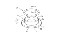
- the metal collar 1 includes a cylindrical main body 10 and a flange 11 extending outward from one end (the lower end in the figure) of the peripheral side surface 1 c of the main body 10. An insertion hole 12 through which a bolt is inserted is formed at the center of the main body 10.
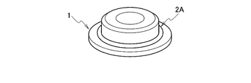
- the metal collar 1 further includes an annular member 2A. The annular member 2A will be described in detail later.
- the metal collar 1 is fixed to the resin member 3 by the inner surface 1d of the flange 11 and the peripheral side surface 1c of the main body 10 (see FIG. 3D). That is, the inner surface 1d and the peripheral side surface 1c are to be applied with a viscous fluid (adhesive, sealant, etc .; hereinafter simply referred to as a viscous fluid) that bonds the metal collar 1 and the resin member 3 together.
- a viscous fluid adheres to these surfaces, the fastening force at the fastening surface will be reduced, or the dimensional accuracy of fastening will be reduced.
- a tapered surface 1b is formed between the annular surface 1a and the peripheral side surface 1c so that the main body 10 can be easily inserted into the through hole 30 formed in the resin member 3. .
- a viscous fluid it is not necessary to apply a viscous fluid to the taper surface 1b or the peripheral surface 1e of the flange 11, it does not affect the fastening of the parts attached to the resin member 3, and may adhere.
- the metal collar 1 of the present embodiment also includes the annular member 2A that is fitted into the boundary portion between the main body 10 and the flange 11 (that is, the boundary portion between the peripheral side surface 1c and the inner surface 1d).
- the annular member 2A of the present embodiment is an annular tube.
- the annular member 2A includes an outer skin (outer shell) formed of resin, rubber, or the like, and a viscous fluid contained in the outer skin.
- the annular member 2 ⁇ / b> A is formed so that its inner diameter is slightly smaller than the outer diameter of the main body 10. Accordingly, the annular member 2 ⁇ / b> A fitted in the boundary portion between the main body 10 and the flange 11 does not easily fall off from the main body 10.
- the viscous fluid of this embodiment is a one-component adhesive.
- the adhesive is cured by evaporating the solvent in the adhesive, reacting with oxygen or moisture in the air, or curing by receiving heat or ultraviolet rays.
- the pressure applied to the outer skin increases the pressure of the internal adhesive, causing the outer skin to break (break or break). When the outer skin breaks, the internal adhesive leaks from the outer skin and hardens.
- a two-component mixed adhesive may be used as the adhesive (annular member 2A 'as a modification of the annular member 2A).
- annular member 2A annular member 2A ′.
- a partition wall 21 is provided inside the outer skin 20 of the annular member 2A ′. It is divided into two compartments.
- the main agent 22 is filled in one section, and the curing agent 23 is filled in the other section.
- the pressure in the two compartments increases and the skin 20 breaks.
- both the main agent 22 and the curing agent 23 leak from the outer skin 20 and mix and harden.
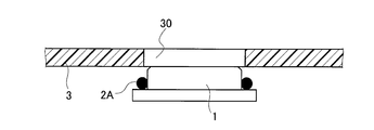
- the resin member 3 of the present embodiment is a plate material made of FRP (more specifically, CFRP). As shown in FIG. 3A, a through hole 30 is formed in advance at a position where the metal collar 1 of the resin member 3 is attached. In addition, as described above, the annular member 2 ⁇ / b> A is fitted into the boundary portion between the main body 10 and the flange 11 in the metal collar 1 in advance.
- the main body 10 of the metal collar 1 is inserted into the through hole 30.
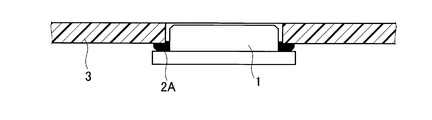
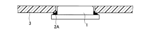
- the annular member 2 ⁇ / b> A contacts the inner edge of the through hole 30. If the pressure is applied to the annular member 2A by pressing the flange 11 as it is, as shown in FIG. 3C, the outer skin of the annular member 2A breaks, and the internal adhesive leaks out. The leaked adhesive 2 spreads along the peripheral side surface 1c of the main body 10 and the inner surface 1d of the flange 11, and is cured in a state in which the gap between the metal collar 1 and the resin member 3 is filled as shown in FIG. 3D. To do.
- the bolt is inserted into the insertion hole 12 of the metal collar 1 from the flange 11 side. Further, after a bolt is inserted into a bolt hole formed in a component fixed to the resin member 3, a nut is screwed into the bolt. The parts are fixed to the resin member 3 by fastening the bolts and nuts.
- the annular surface 1a that is a contact surface with the component of the metal collar 1 is slightly protruded from the surface of the resin member 3 (see FIG. 3D). Therefore, when the component to be fixed is a flat plate or the like, a gap is formed between the component and the resin member 3. Further, the outer surface 1f of the flange 11 serves as a seat surface of the bolt.
- the viscous fluid (adhesive) is contained in the annular member 2A without being exposed to the outside, so that the annular member 2A is not directly in contact with the viscous fluid. It can be fitted into the main body 10 of the metal collar 1. That is, the viscous fluid is not applied to the metal collar 1, and the metal collar 1 can be produced with good workability. Further, when the metal collar 1 is attached to the resin member 3, the metal collar 1 can be attached to the resin member 3 with good workability without directly contacting the viscous fluid. The state of the attachment portion after the metal collar 1 is attached to the resin member 3 is also good.
- the metal collar of this embodiment differs from the annular member 2A of the first embodiment only in the annular member 2B.
- the method of attaching the metal collar and the resin member 3 according to this embodiment is the same as the metal collar 1 and the method of attaching (see FIGS. 3A to 3D) of the first embodiment. Accordingly, only the annular member 2B will be described below.
- the annular member 2B of the present embodiment is also an annular tube.
- the annular member 2A of the first embodiment had only one section inside thereof (two sections in the modification shown in FIG. 2).
- a plurality of partition walls 24 are provided inside the outer skin 20, and the inner portion of the outer skin 20 is divided into a plurality of sections 25 in the circumferential direction.
- the partition walls 24 are provided at equal intervals in the circumferential direction, and the volumes of the sections 25 are equal.
- the partition walls 24 may not be provided at equal intervals in the circumferential direction.
- the annular member 2B is also formed so that its inner diameter is slightly smaller than the outer diameter of the main body 10.
- Each compartment 25 contains a one-pack type adhesive (viscous fluid).
- a one-pack type adhesive viscous fluid
- the main component and the curing agent of the two-component adhesive can be alternately included in the plurality of compartments 25. Even in this case, the adhesive can be evenly leaked in the circumferential direction. As a result, the metal collar 1 can be stably attached by the resin member 3.
- the main agent and the curing agent may not be alternately included in the compartments 25 and may be included in a predetermined repeating pattern in the circumferential direction (for example, the pattern of “main agent, main agent, curing agent” is repeated).
- the metal collar of this embodiment also differs from the annular member 2A of the first embodiment only in the annular member 2C.
- the method of attaching the metal collar and the resin member 3 according to this embodiment is the same as the metal collar 1 and the method of attaching (see FIGS. 3A to 3D) of the first embodiment. Accordingly, only the annular member 2C will be described below.
- the annular member 2 ⁇ / b> C of the present embodiment is configured by connecting a plurality of spherical outer skins containing an adhesive (viscous fluid) in an annular shape. That is, each spherical outer skin is formed as a spherical capsule 27 containing an adhesive. The plurality of spherical capsules are connected in a ring by being fixed on the seal ring 26 side by side.
- the annular member 2 ⁇ / b> C is also formed so that its minimum inner diameter is slightly smaller than the outer diameter of the main body 10.
- Each spherical capsule 27 contains a one-pack type adhesive.
- the pressure of the adhesive in each spherical capsule 27 increases.
- the outer capsule breaks for each spherical capsule 27 and the adhesive leaks and hardens. That is, the adhesive can be leaked evenly in the circumferential direction.
- the metal collar 1 can be stably attached by the resin member 3.
- the seal ring 26 is left between the metal collar 1 and the resin member 3, and seals between the metal collar 1 and the resin member 3.
- the main component and the curing agent of the two-component adhesive agent can be alternately included in the plurality of spherical capsules 27. Even in this case, the adhesive can be evenly leaked in the circumferential direction. As a result, the metal collar 1 can be stably attached by the resin member 3.
- the main agent and the curing agent may not be alternately encapsulated in the spherical capsule 27, and may be encapsulated in a predetermined repeating pattern in the circumferential direction (for example, the pattern of “main agent, main agent, curing agent” is repeated). .
- the structure of the annular member in which “a plurality of spherical outer shells containing adhesive (viscous fluid) are connected in a ring shape” is obtained by twisting the annular tube as in Embodiment 1 at a plurality of locations in the circumferential direction (of sausage As well).
- a connecting member such as the seal ring 26 described above is not necessary.
- the term “spherical” in this embodiment includes not only a perfect spherical shape but also a shape that is long in the circumferential direction (such as an elongated sphere and an ellipsoid, which are curved in the circumferential direction). May be)
- the metal collar of this embodiment is also different from the annular member 2A of the first embodiment only in the annular member 2D.
- the method of attaching the metal collar and the resin member 3 according to this embodiment is the same as the metal collar 1 and the method of attaching (see FIGS. 3A to 3D) of the first embodiment. Accordingly, only the annular member 2D will be described below.
- the annular member 2D of the present embodiment includes a two-component adhesive (viscous fluid) composed of a main agent and a curing agent.
- the annular member 2D includes a first annular tube 28 for a main agent and a second annular tube 29 for a curing agent, and the first annular tube 28 and the second annular tube 29 are intertwined with each other.
- Each structure of the 1st annular tube 28 and the 2nd annular tube 29 is the same as that of 2 A of annular members of 1st Embodiment except thickness.
- the first annular tube 28 contains the main agent in its outer skin, and the second annular tube 29 contains the curing agent in its outer skin.
- the annular member 2D is also formed so that its inner diameter is slightly smaller than the outer diameter of the main body 10.
- the metal collar 1 provided with the annular member 2D when the metal collar 1 provided with the annular member 2D is attached to the resin member 3, if pressure is applied to the first annular tube 28 and the second annular tube 29, the internal main agent / curing agent The pressure increases, the outer skin breaks, the main agent and the curing agent leak and harden. Since the first annular tube 28 and the second annular tube 29 are intertwined, the main agent and the curing agent are uniformly mixed. As a result, the metal collar 1 can be stably attached by the resin member 3.
- Each of the first annular tube 28 and the second annular tube 29 may have the structure of the annular member 2B of the second embodiment having a plurality of sections in the circumferential direction (see FIG. 4).
Landscapes
- Engineering & Computer Science (AREA)
- General Engineering & Computer Science (AREA)
- Mechanical Engineering (AREA)
- Bolts, Nuts, And Washers (AREA)
- Adhesives Or Adhesive Processes (AREA)
Abstract
樹脂部材へのカラー取付方法によれば、樹脂部材に形成された貫通孔に金属カラーを取り付ける。金属カラーは、円筒状の本体と、当該本体の周側面から外方に延出されたフランジとを有している。上記取付方法では、金属カラーの本体の周側面とフランジとの境界部に、圧力負荷によって破断する外皮内に粘着作用を有する粘性流体を内包した環状部材を予め嵌め込む。そして、円筒状の本体を貫通孔に挿入してフランジを樹脂部材に押圧する。この結果、外皮が破断して粘性流体が外皮から漏出して、粘性流体によって金属カラーが樹脂部材に取り付けられる。
Description
本発明は、樹脂部材へのカラー取付方法及び金属カラーに関する。
金属カラーをFRP(Fiber Reinforced Plastics)などの樹脂部材に形成された貫通孔に取り付け、金属カラーを介して樹脂部材に別の部品を固定する場合がある。CFRP(Carbon Fiber Reinforced Plastics)の炭素繊維は導電性を有しているため、電食を防止するために粘性流体(接着剤やシーラントなど)を金属カラーに塗布してから、金属カラーが樹脂部材の貫通孔に取り付けられる。
下記特許文献1は、樹脂部材の貫通孔に取り付けられた、フランジを有する金属カラーを開示している。金属カラーのフランジの内面と貫通孔周囲の樹脂部材の表面との間、及び、金属カラーの周側面と貫通孔の内周縁との間に接着剤が配されており、この接着剤によって金属カラーが貫通孔に取り付けられている。
特許文献1に開示された取付構造では、金属カラーのフランジの内面(又は、樹脂部材の貫通孔の周囲)及び金属カラーの周側面(又は、貫通孔の内周縁)に粘性流体(接着剤)を塗布する作業が必要になる。また、金属カラーには粘性流体を付着させたくない面もある。例えば、金属カラーを介して固定される別の部品との接触面には、粘性流体を付着させたくない。このため、接着剤の塗布作業は非常に手間がかかる。この結果、金属カラーを取り付けた樹脂部材の製造時間は長くなり、かつ、製造コストは増加する。
本発明の目的は、金属カラーの樹脂部材への取付作業性を向上させることにある。
本発明の特徴は、金属カラーにおける本体の周側面とフランジとの境界部に圧力負荷によって破断する外皮内に粘着作用を有する粘性流体を内包した環状部材を予め嵌め込み、金属カラーの本体を樹脂部材の貫通孔に挿入してフランジを樹脂部材に押圧する。その結果、外皮が破断して粘性流体が外皮から漏出する。
上記特徴によれば、金属カラーの樹脂部材への取付作業性を向上させることができる。
以下、金属カラー及び樹脂部材へのカラー取付方法の実施形態について、図面を参照しつつ説明する。
まず、第1実施形態に係る金属カラーについて、図1A及び図1Bを参照しつつ説明する。金属カラー1は、円筒状の本体10と、本体10の周側面1cの一端(図では下端)から外方に延出されたフランジ11とからなる。本体10の中央には、ボルトが挿通される挿通孔12が形成されている。金属カラー1は、環状部材2Aもさらに備えている。環状部材2Aについては追って詳しく説明する。
金属カラー1は、フランジ11の内面1dと本体10の周側面1cとで樹脂部材3に固定される(図3D参照)。即ち、内面1dと周側面1cとには、金属カラー1と樹脂部材3とを結合させる、粘着作用を有する粘性流体(接着剤やシーラントなど:以下単に粘性流体という)を塗布したい。しかし、金属カラー1を介して樹脂部材3に取り付けられる部品や締結具(ボルト・ナットなど)と接触する、本体10の環状面1a及びフランジ11の外面1fには粘性流体を付着させたくない。これらの面に粘性流体が付着すると、締結面での締結力が低下したり、締結の寸法精度が低下したりしてしまう。
本実施形態の金属カラー1には、環状面1aと周側面1cとの間に、本体10を樹脂部材3に形成された貫通孔30に挿入しやすくするためのテーパー面1bが形成されている。このテーパー面1bやフランジ11の周面1eには粘性流体を塗布する必要はないが、樹脂部材3に取り付けられる部品の締結には影響しないので付着しても構わない。
本実施形態の金属カラー1は、上述したように、本体10とフランジ11との境界部(即ち、周側面1cと内面1dとの境界部)に嵌め込まれる環状部材2Aも有している。本実施形態の環状部材2Aは、環状チューブである。環状部材2Aは、樹脂やゴムなどで形成された外皮(外殻)と、この外皮に内包された粘性流体とからなる。環状部材2Aは、その内径が本体10の外径よりも若干小さくなるように形成されている。従って、本体10とフランジ11との境界部に嵌め込まれた環状部材2Aは、本体10から容易に脱落することはない。
本実施形態の粘性流体は一液型接着剤である。接着剤は、接着剤中の溶剤が蒸発して硬化したり、空気中の酸素や水分と反応して硬化したり、熱や紫外線を受けて硬化したりする。外皮への圧力負荷によって内部の接着剤の圧力が高まって外皮が破断する(破れる・割れる)。外皮が破断すると、内部の接着剤は外皮から漏出して硬化する。
なお、接着剤は、二液混合型接着剤が用いられてもよい(環状部材2Aの変形例としての環状部材2A’)。この場合は、例えば、図2(図1A中のII-II線断面図)に示されるように、環状部材2A’の外皮20の内部に隔壁21が設けられており、隔壁21によって内部が二つの区画に分割されている。一方の区画に主剤22が充填され、他方の区画に硬化剤23が充填される。外皮20に圧力が負荷されると二つの区画内の圧力が高まって外皮20が破断する。外皮20が破断すると、主剤22及び硬化剤23の両方が外皮20から漏出して混ざり合って硬化する。
次に、上述した環状部材2Aを備えた金属カラー1を樹脂部材3に取り付ける方法について、図3A~図3Dを参照しつつ説明する。本実施形態の樹脂部材3は、FRP(より具体的にはCFRP)製の板材である。図3Aに示されるように、樹脂部材3の金属カラー1が取り付けられる位置には、予め貫通孔30が形成されている。また、金属カラー1には、上述したように、予め、本体10とフランジ11との境界部に環状部材2Aが嵌め込まれている。
次に、図3Bに示されるように、貫通孔30に、金属カラー1の本体10を挿入させる。環状部材2Aは、貫通孔30の内縁と接触する。そのまま、フランジ11を押圧して環状部材2Aに圧力を負荷すると、図3Cに示されるように、環状部材2Aの外皮が破断して、内部の接着剤が漏出する。漏出した接着剤2は、本体10の周側面1c及びフランジ11の内面1dに沿って広がり、図3Dに示されるように、金属カラー1と樹脂部材3との間の隙間を埋めた状態で硬化する。
金属カラー1の挿通孔12にボルトがフランジ11側から挿入される。さらに、樹脂部材3に固定される部品に形成されたボルト孔にボルトが挿通された後、ボルトにナットが螺合される。ボルト・ナットが締結されることで、樹脂部材3に部品が固定される。金属カラー1の部品との接触面となる環状面1aは、樹脂部材3の表面よりも若干突出されている(図3D参照)。従って、固定される部品が平板などの場合は、部品と樹脂部材3との間には隙間が形成される。また、フランジ11の外面1fはボルトの座面となる。
本実施形態の金属カラー1(カラー取付方法)によれば、粘性流体(接着剤)は外部に露出せずに環状部材2Aに内包されているので、粘性流体を直接触ることなく環状部材2Aを金属カラー1の本体10に嵌め込むことができる。即ち、粘性流体を金属カラー1に塗布することはなく、良好な作業性で金属カラー1を作成することができる。また、金属カラー1を樹脂部材3に取り付けるときも粘性流体を直接触ることなく、良好な作業性で金属カラー1を樹脂部材3に取り付けることができる。金属カラー1を樹脂部材3に取り付けた後の取付部の状態も良好になる。
次に、第2実施形態に係る金属カラーについて、図4を参照しつつ説明する。本実施形態の金属カラーは、その環状部材2Bのみが第1実施形態の環状部材2Aと異なる。なお、本実施形態の金属カラー及び樹脂部材3への取付方法は、第1実施形態の金属カラー1及び取付方法(図3A~図3D参照)と同じである。従って、以下には、環状部材2Bについてのみ説明する。
図4に示されるように、本実施形態の環状部材2Bも、環状チューブである。第1実施形態の環状部材2Aは、その内部に一つの区画のみを有していた(図2に示される変形例では二つの区画)。しかし、本実施形態の環状部材2Bでは、その外皮20の内部に複数の隔壁24が設けられており、外皮20の内部が周方向に複数の区画25に分割されている。本実施形態では、隔壁24は周方向に等間隔に設けられており、各区画25の容積は等しい。ただし、隔壁24は周方向に等間隔に設けられなくてもよい。なお、環状部材2Bも、その内径が本体10の外径よりも若干小さくなるように形成されている。
各区画25には、一液型の接着剤(粘性流体)が内包されている。本実施形態によれば、環状部材2Bを備えた金属カラー1を樹脂部材3に取り付ける際に、外皮20に圧力が負荷されると各区画25内の接着剤の圧力が高くなり、区画25毎に外皮20が破断して接着剤が漏出して硬化する。即ち、接着剤を周方向に均等に漏出させることができる。この結果、金属カラー1を樹脂部材3により安定的に取り付けることができる。
なお、複数の区画25に、二液型接着剤の主剤と硬化剤とを交互に内包させることもできる。このようにしても、接着剤を周方向に均等に漏出させることができる。この結果、金属カラー1を樹脂部材3により安定的に取り付けることができる。主剤と硬化剤とは、交互に区画25に内包されなくてもよく、周方向に所定の繰り返しパターンで内包されてもよい(例えば、「主剤、主剤、硬化剤」のパターンが繰り返される)。
次に、第3実施形態に係る金属カラーについて、図5を参照しつつ説明する。本実施形態の金属カラーも、その環状部材2Cのみが第1実施形態の環状部材2Aと異なる。なお、本実施形態の金属カラー及び樹脂部材3への取付方法も、第1実施形態の金属カラー1及び取付方法(図3A~図3D参照)と同じである。従って、以下には、環状部材2Cについてのみ説明する。
図5に示されるように、本実施形態の環状部材2Cは、接着剤(粘性流体)を内包する球状の外皮が複数個環状に連結されて構成されている。即ち、球状の各外皮は、接着剤を内包する球状カプセル27として形成されている。複数の球状カプセルは、シールリング26上に並べて固定されることで、環状に連結されている。なお、環状部材2Cも、その最小内径が本体10の外径よりも若干小さくなるように形成されている。
各球状カプセル27には、一液型の接着剤が内包されている。本実施形態によれば、環状部材2Cを備えた金属カラー1を樹脂部材3に取り付ける際に、外皮(球状カプセル27)に圧力が負荷されると各球状カプセル27内の接着剤の圧力が高くなり、球状カプセル27毎に外皮が破断して接着剤が漏出して硬化する。即ち、接着剤を周方向に均等に漏出させることができる。この結果、金属カラー1を樹脂部材3により安定的に取り付けることができる。また、シールリング26は金属カラー1と樹脂部材3との間に残され、金属カラー1と樹脂部材3との間をシールする。
なお、複数の球状カプセル27に、二液型接着剤の主剤と硬化剤とを交互に内包させることもできる。このようにしても、接着剤を周方向に均等に漏出させることができる。この結果、金属カラー1を樹脂部材3により安定的に取り付けることができる。主剤と硬化剤とは、交互に球状カプセル27に内包されなくてもよく、周方向に所定の繰り返しパターンで内包されてもよい(例えば、「主剤、主剤、硬化剤」のパターンが繰り返される)。
「接着剤(粘性流体)を内包する球状の外皮が複数個環状に連結された」環状部材の構造は、実施形態1のような環状チューブを周方向に複数個所で捩じって(ソーセージのように)形成することもできる。この場合は、上述したシールリング26のような連結部材は必要ない。また、本実施形態における「球状」の語は、完全な球形のみでなく、周方向に長い形状も含む(長球[elongated sphere]や楕円体[ellipsoid]など、これらは周方向に湾曲していてもよい)。
次に、第4実施形態に係る金属カラーについて、図6を参照しつつ説明する。本実施形態の金属カラーも、その環状部材2Dのみが第1実施形態の環状部材2Aと異なる。なお、本実施形態の金属カラー及び樹脂部材3への取付方法も、第1実施形態の金属カラー1及び取付方法(図3A~図3D参照)と同じである。従って、以下には、環状部材2Dについてのみ説明する。
本実施形態の環状部材2Dは、主剤及び硬化剤からなる二液型接着剤(粘性流体)を内包するものである。図6に示されるように、環状部材2Dは、主剤用の第1環状チューブ28と硬化剤用の第2環状チューブ29とからなり、第1環状チューブ28及び第2環状チューブ29が互いに絡み合っている。第1環状チューブ28及び第2環状チューブ29のそれぞれの構造は、太さを除いて第1実施形態の環状部材2Aと同じである。第1環状チューブ28は、その外皮に主剤を内包しており、第2環状チューブ29は、その外皮に硬化剤を内包している。なお、環状部材2Dも、その内径が本体10の外径よりも若干小さくなるように形成されている。
本実施形態によれば、環状部材2Dを備えた金属カラー1を樹脂部材3に取り付ける際に、第1環状チューブ28及び第2環状チューブ29に圧力が負荷されると内部の主剤・硬化剤の圧力が高くなり、外皮が破断して主剤及び硬化剤が漏出して硬化する。第1環状チューブ28及び第2環状チューブ29は絡み合っているため、主剤と硬化剤とが均一に混ざり合う。この結果、金属カラー1を樹脂部材3により安定的に取り付けることができる。第1環状チューブ28及び第2環状チューブ29のそれぞれが、周方向に複数の区画を有する第2実施形態の環状部材2Bの構造を有してもよい(図4参照)。
本発明によれば、金属カラーを樹脂部材の貫通孔に取り付けるカラー取付方法を提供でき、また、部材に形成された貫通孔に取り付けられる金属カラーを提供できる。
1 金属カラー
10 本体
11 フランジ
2A~2D,2A’ 環状部材
2 接着剤(粘性流体)
20 外皮
21 隔壁
22 主剤(接着剤:粘性流体)
23 硬化剤(接着剤:粘性流体)
25 区画
28 第1環状チューブ
29 第2環状チューブ
3 樹脂部材
30 貫通孔
10 本体
11 フランジ
2A~2D,2A’ 環状部材
2 接着剤(粘性流体)
20 外皮
21 隔壁
22 主剤(接着剤:粘性流体)
23 硬化剤(接着剤:粘性流体)
25 区画
28 第1環状チューブ
29 第2環状チューブ
3 樹脂部材
30 貫通孔
Claims (5)
- 円筒状の本体と当該本体の周側面から外方に延出されたフランジとを有する金属カラーを樹脂部材に形成された貫通孔に取り付ける、樹脂部材へのカラー取付方法であって、
前記本体の前記周側面と前記フランジとの境界部に、圧力負荷によって破断する外皮内に粘着作用を有する粘性流体を内包した環状部材を予め嵌め込み、
前記本体を前記貫通孔に挿入して前記フランジを前記樹脂部材に押圧させることで、前記外皮を破断させて前記粘性流体を前記外皮から漏出させる、樹脂部材へのカラー取付方法。 - 部材に形成された貫通孔に取り付けられる金属カラーであって、
円筒状の本体と、
前記本体の周側面から外方に延出されたフランジと、
前記本体の前記周側面と前記フランジとの境界部に嵌め込まれた環状部材とを備えており、
前記環状部材は、圧力負荷によって破断する外皮と、当該外皮に内包された粘着作用を有する粘性流体とを有している、金属カラー。 - 請求項2に記載の金属カラーであって、
前記環状部材が環状チューブであり、前記外皮の内部が周方向に複数の区画に分割されている、金属カラー。 - 請求項2に記載の金属カラーであって、
前記粘性流体を内包する球状の前記外皮が複数個環状に連結されて、前記環状部材が構成されている、金属カラー。 - 請求項2に記載の金属カラーであって、
前記粘性流体が、主剤及び硬化剤からなる二液混合型接着剤であり、
前記環状部材が前記主剤用の第1環状チューブと前記硬化剤用の第2環状チューブとからなり、前記第1及び第2環状チューブが互いに絡み合っている、金属カラー。
Priority Applications (1)
| Application Number | Priority Date | Filing Date | Title |
|---|---|---|---|
| PCT/JP2017/016465 WO2018198214A1 (ja) | 2017-04-26 | 2017-04-26 | 樹脂部材へのカラー取付方法、及び、金属カラー |
Applications Claiming Priority (1)
| Application Number | Priority Date | Filing Date | Title |
|---|---|---|---|
| PCT/JP2017/016465 WO2018198214A1 (ja) | 2017-04-26 | 2017-04-26 | 樹脂部材へのカラー取付方法、及び、金属カラー |
Publications (1)
| Publication Number | Publication Date |
|---|---|
| WO2018198214A1 true WO2018198214A1 (ja) | 2018-11-01 |
Family
ID=63919000
Family Applications (1)
| Application Number | Title | Priority Date | Filing Date |
|---|---|---|---|
| PCT/JP2017/016465 Ceased WO2018198214A1 (ja) | 2017-04-26 | 2017-04-26 | 樹脂部材へのカラー取付方法、及び、金属カラー |
Country Status (1)
| Country | Link |
|---|---|
| WO (1) | WO2018198214A1 (ja) |
Citations (6)
| Publication number | Priority date | Publication date | Assignee | Title |
|---|---|---|---|---|
| JPS4961544A (ja) * | 1972-10-11 | 1974-06-14 | ||
| JPS49133749A (ja) * | 1973-05-02 | 1974-12-23 | ||
| JPS51723B1 (ja) * | 1970-09-11 | 1976-01-10 | ||
| JPS56147965A (en) * | 1980-04-16 | 1981-11-17 | Mitsubishi Electric Corp | Sealing device at interconnecting part |
| JP2007078169A (ja) * | 2005-09-15 | 2007-03-29 | Sugano Atsushi | ビスの弛み止めリング |
| JP2015086942A (ja) * | 2013-10-30 | 2015-05-07 | トヨタ自動車株式会社 | 締結構造 |
-
2017
- 2017-04-26 WO PCT/JP2017/016465 patent/WO2018198214A1/ja not_active Ceased
Patent Citations (6)
| Publication number | Priority date | Publication date | Assignee | Title |
|---|---|---|---|---|
| JPS51723B1 (ja) * | 1970-09-11 | 1976-01-10 | ||
| JPS4961544A (ja) * | 1972-10-11 | 1974-06-14 | ||
| JPS49133749A (ja) * | 1973-05-02 | 1974-12-23 | ||
| JPS56147965A (en) * | 1980-04-16 | 1981-11-17 | Mitsubishi Electric Corp | Sealing device at interconnecting part |
| JP2007078169A (ja) * | 2005-09-15 | 2007-03-29 | Sugano Atsushi | ビスの弛み止めリング |
| JP2015086942A (ja) * | 2013-10-30 | 2015-05-07 | トヨタ自動車株式会社 | 締結構造 |
Similar Documents
| Publication | Publication Date | Title |
|---|---|---|
| RU2554606C2 (ru) | Ультразвуковой преобразователь для применения в текучей среде | |
| JP7118563B2 (ja) | シール部材および防水構造 | |
| US3224795A (en) | Flanged fitting with a reinforcing sleeve | |
| CN109128896B (zh) | 固定装置以及制造固定装置中的弹性构件的方法 | |
| JPH07101074B2 (ja) | 流体通路を構成する可撓性管部材の接続方法 | |
| KR950014644A (ko) | 코러게이트 나선관용 이음구와 이음구 부착코러게이트 나선관과 그 제조방법/및 이음구 부착 코러게이트 나선관으로의 나선관 접속방법 | |
| WO2020039706A1 (ja) | ガスケット | |
| JP2022187796A (ja) | 高圧タンク、及び、その製造方法 | |
| WO2018198214A1 (ja) | 樹脂部材へのカラー取付方法、及び、金属カラー | |
| US20160167320A1 (en) | Self-piercing rivet | |
| US9845903B2 (en) | Hose joint with adhesive | |
| KR200436750Y1 (ko) | 관체 플랜지 가스켓 | |
| JP7331389B2 (ja) | 気密構造の製造方法 | |
| JP5018100B2 (ja) | 圧力容器及び圧力容器製造方法 | |
| EP3594537A1 (en) | Gasket | |
| US9878810B2 (en) | Self-contained stud adhesive bonding apparatus and method of use | |
| JPS5836210B2 (ja) | 管状シヤフトを端部取付部材に接着する方法 | |
| JP2020090200A (ja) | 車両搭載機器のハウジング構造 | |
| TWI686562B (zh) | 長形流路構件及塑膠容器以及黏性液體吐出裝置 | |
| KR20190126404A (ko) | 스테이터 및 일축 편심 나사 펌프 | |
| KR101323175B1 (ko) | 플라스틱 주름관의 방수 연결구 | |
| JPS63275856A (ja) | 密封装置 | |
| JP7677219B2 (ja) | 高圧タンク | |
| JP2018013139A (ja) | 管継手 | |
| JPH0241435Y2 (ja) |
Legal Events
| Date | Code | Title | Description |
|---|---|---|---|
| 121 | Ep: the epo has been informed by wipo that ep was designated in this application |
Ref document number: 17907911 Country of ref document: EP Kind code of ref document: A1 |
|
| NENP | Non-entry into the national phase |
Ref country code: DE |
|
| 122 | Ep: pct application non-entry in european phase |
Ref document number: 17907911 Country of ref document: EP Kind code of ref document: A1 |
|
| NENP | Non-entry into the national phase |
Ref country code: JP |