WO2018193833A1 - 内燃機関の排気処理装置 - Google Patents
内燃機関の排気処理装置 Download PDFInfo
- Publication number
- WO2018193833A1 WO2018193833A1 PCT/JP2018/014255 JP2018014255W WO2018193833A1 WO 2018193833 A1 WO2018193833 A1 WO 2018193833A1 JP 2018014255 W JP2018014255 W JP 2018014255W WO 2018193833 A1 WO2018193833 A1 WO 2018193833A1
- Authority
- WO
- WIPO (PCT)
- Prior art keywords
- air
- fuel ratio
- internal combustion
- combustion engine
- exhaust
- Prior art date
- Legal status (The legal status is an assumption and is not a legal conclusion. Google has not performed a legal analysis and makes no representation as to the accuracy of the status listed.)
- Ceased
Links
Images


Classifications
-
- F—MECHANICAL ENGINEERING; LIGHTING; HEATING; WEAPONS; BLASTING
- F01—MACHINES OR ENGINES IN GENERAL; ENGINE PLANTS IN GENERAL; STEAM ENGINES
- F01N—GAS-FLOW SILENCERS OR EXHAUST APPARATUS FOR MACHINES OR ENGINES IN GENERAL; GAS-FLOW SILENCERS OR EXHAUST APPARATUS FOR INTERNAL-COMBUSTION ENGINES
- F01N3/00—Exhaust or silencing apparatus having means for purifying, rendering innocuous, or otherwise treating exhaust
- F01N3/08—Exhaust or silencing apparatus having means for purifying, rendering innocuous, or otherwise treating exhaust for rendering innocuous
- F01N3/10—Exhaust or silencing apparatus having means for purifying, rendering innocuous, or otherwise treating exhaust for rendering innocuous by thermal or catalytic conversion of noxious components of exhaust
- F01N3/101—Three-way catalysts
-
- F—MECHANICAL ENGINEERING; LIGHTING; HEATING; WEAPONS; BLASTING
- F01—MACHINES OR ENGINES IN GENERAL; ENGINE PLANTS IN GENERAL; STEAM ENGINES
- F01N—GAS-FLOW SILENCERS OR EXHAUST APPARATUS FOR MACHINES OR ENGINES IN GENERAL; GAS-FLOW SILENCERS OR EXHAUST APPARATUS FOR INTERNAL-COMBUSTION ENGINES
- F01N13/00—Exhaust or silencing apparatus characterised by constructional features
- F01N13/009—Exhaust or silencing apparatus characterised by constructional features having two or more separate purifying devices arranged in series
-
- F—MECHANICAL ENGINEERING; LIGHTING; HEATING; WEAPONS; BLASTING
- F01—MACHINES OR ENGINES IN GENERAL; ENGINE PLANTS IN GENERAL; STEAM ENGINES
- F01N—GAS-FLOW SILENCERS OR EXHAUST APPARATUS FOR MACHINES OR ENGINES IN GENERAL; GAS-FLOW SILENCERS OR EXHAUST APPARATUS FOR INTERNAL-COMBUSTION ENGINES
- F01N3/00—Exhaust or silencing apparatus having means for purifying, rendering innocuous, or otherwise treating exhaust
- F01N3/02—Exhaust or silencing apparatus having means for purifying, rendering innocuous, or otherwise treating exhaust for cooling, or for removing solid constituents of, exhaust
- F01N3/021—Exhaust or silencing apparatus having means for purifying, rendering innocuous, or otherwise treating exhaust for cooling, or for removing solid constituents of, exhaust by means of filters
- F01N3/023—Exhaust or silencing apparatus having means for purifying, rendering innocuous, or otherwise treating exhaust for cooling, or for removing solid constituents of, exhaust by means of filters using means for regenerating the filters, e.g. by burning trapped particles
-
- F—MECHANICAL ENGINEERING; LIGHTING; HEATING; WEAPONS; BLASTING
- F01—MACHINES OR ENGINES IN GENERAL; ENGINE PLANTS IN GENERAL; STEAM ENGINES
- F01N—GAS-FLOW SILENCERS OR EXHAUST APPARATUS FOR MACHINES OR ENGINES IN GENERAL; GAS-FLOW SILENCERS OR EXHAUST APPARATUS FOR INTERNAL-COMBUSTION ENGINES
- F01N3/00—Exhaust or silencing apparatus having means for purifying, rendering innocuous, or otherwise treating exhaust
- F01N3/02—Exhaust or silencing apparatus having means for purifying, rendering innocuous, or otherwise treating exhaust for cooling, or for removing solid constituents of, exhaust
- F01N3/021—Exhaust or silencing apparatus having means for purifying, rendering innocuous, or otherwise treating exhaust for cooling, or for removing solid constituents of, exhaust by means of filters
- F01N3/033—Exhaust or silencing apparatus having means for purifying, rendering innocuous, or otherwise treating exhaust for cooling, or for removing solid constituents of, exhaust by means of filters in combination with other devices
- F01N3/035—Exhaust or silencing apparatus having means for purifying, rendering innocuous, or otherwise treating exhaust for cooling, or for removing solid constituents of, exhaust by means of filters in combination with other devices with catalytic reactors
-
- F—MECHANICAL ENGINEERING; LIGHTING; HEATING; WEAPONS; BLASTING
- F02—COMBUSTION ENGINES; HOT-GAS OR COMBUSTION-PRODUCT ENGINE PLANTS
- F02D—CONTROLLING COMBUSTION ENGINES
- F02D43/00—Conjoint electrical control of two or more functions, e.g. ignition, fuel-air mixture, recirculation, supercharging or exhaust-gas treatment
-
- F—MECHANICAL ENGINEERING; LIGHTING; HEATING; WEAPONS; BLASTING
- F01—MACHINES OR ENGINES IN GENERAL; ENGINE PLANTS IN GENERAL; STEAM ENGINES
- F01N—GAS-FLOW SILENCERS OR EXHAUST APPARATUS FOR MACHINES OR ENGINES IN GENERAL; GAS-FLOW SILENCERS OR EXHAUST APPARATUS FOR INTERNAL-COMBUSTION ENGINES
- F01N2430/00—Influencing exhaust purification, e.g. starting of catalytic reaction, filter regeneration, or the like, by controlling engine operating characteristics
- F01N2430/06—Influencing exhaust purification, e.g. starting of catalytic reaction, filter regeneration, or the like, by controlling engine operating characteristics by varying fuel-air ratio, e.g. by enriching fuel-air mixture
-
- Y—GENERAL TAGGING OF NEW TECHNOLOGICAL DEVELOPMENTS; GENERAL TAGGING OF CROSS-SECTIONAL TECHNOLOGIES SPANNING OVER SEVERAL SECTIONS OF THE IPC; TECHNICAL SUBJECTS COVERED BY FORMER USPC CROSS-REFERENCE ART COLLECTIONS [XRACs] AND DIGESTS
- Y02—TECHNOLOGIES OR APPLICATIONS FOR MITIGATION OR ADAPTATION AGAINST CLIMATE CHANGE
- Y02T—CLIMATE CHANGE MITIGATION TECHNOLOGIES RELATED TO TRANSPORTATION
- Y02T10/00—Road transport of goods or passengers
- Y02T10/10—Internal combustion engine [ICE] based vehicles
- Y02T10/12—Improving ICE efficiencies
Definitions
- the present disclosure relates to an exhaust treatment device for an internal combustion engine, and more particularly, to an exhaust treatment device for an internal combustion engine including a three-way catalyst and a particle filter as an exhaust purification device for purifying exhaust gas.
- Patent Document 1 discloses that lean combustion is performed for regeneration of a particle filter in a stoichiometric engine. During stoichiometric combustion, the amount of oxygen contained in the exhaust of the engine is very small. Therefore, in the one described in Patent Document 1, oxygen necessary for combustion removal of PM is supplied to the particle filter by performing lean combustion. Like to do.
- the present disclosure has been made in view of the above problems, and provides an exhaust treatment device for an internal combustion engine capable of burning and removing particulate matter collected by a particle filter while suppressing deterioration of exhaust emission.
- an exhaust treatment device for an internal combustion engine capable of burning and removing particulate matter collected by a particle filter while suppressing deterioration of exhaust emission.
- the present disclosure employs the following means in order to solve the above problems.
- the present disclosure is applied to an internal combustion engine in which an exhaust passage is provided with a three-way catalyst that oxidizes or reduces components contained in exhaust and a particulate filter that collects particulate matter contained in the exhaust.
- the present invention relates to an exhaust treatment device that burns and removes the particulate matter collected by the particle filter when a condition is satisfied.
- the amount of nitrogen oxides discharged from the internal combustion engine is equal to or less than a predetermined allowable emission value during the period of combustion removal of the particulate matter collected by the particle filter.
- An air-fuel ratio control unit that controls the air-fuel ratio of the internal combustion engine is provided.
- the air-fuel ratio is controlled so that the amount of nitrogen oxides discharged from the internal combustion engine is less than or equal to the allowable emission value.
- the emission of nitrogen oxides can be suppressed. Thereby, it is possible to burn and remove the particulate matter collected by the particle filter while suppressing the deterioration of the exhaust emission.
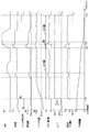
- FIG. 1 is an overall schematic configuration diagram of an engine control system
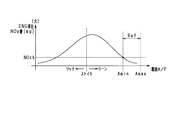
- FIG. 2 is a diagram showing the relationship between the engine exhaust NOx amount and the air-fuel ratio
- FIG. 3 is a diagram illustrating a method for setting the combustion A / F value during regeneration.
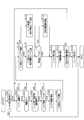
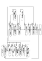
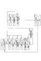
- FIG. 4 is a flowchart showing a processing procedure of the filter regeneration processing according to the first embodiment.
- FIG. 5 is a diagram showing an engine operation region in which filter regeneration can be performed.
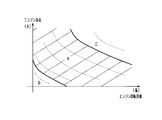
- FIG. 6 is a diagram showing the engine exhaust NOx amount according to the engine load.
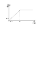
- FIG. 7 is a diagram showing the relationship between the oxygen concentration and the PM combustion rate, FIG.
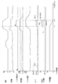
- FIG. 8 is a time chart showing a specific aspect of the filter regeneration processing of the first embodiment.
- FIG. 9 is a flowchart showing a post-injection control process.
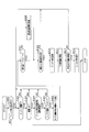
- FIG. 10 is a flowchart illustrating a processing procedure of the filter regeneration processing according to the second embodiment.
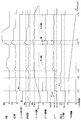
- FIG. 11 is a time chart showing a specific aspect of the filter regeneration processing of the second embodiment.
- FIG. 12 is a flowchart showing the processing procedure of the filter regeneration processing of the third embodiment.
- FIG. 13 is a time chart showing the processing procedure of the filter regeneration processing of the third embodiment.
- FIG. 14 is a diagram for explaining the maximum injection amount in the post injection,
- FIG. 15 is a flowchart illustrating a processing procedure of the filter regeneration processing according to the fourth embodiment.
- FIG. 16 is a time chart showing the processing procedure of the filter regeneration processing of the fourth embodiment.
- the present embodiment is an in-vehicle multi-cylinder four-cycle gasoline engine that is an internal combustion engine, and an engine control system is constructed for an in-cylinder injection and spark ignition engine.
- an electronic control unit hereinafter referred to as ECU
- FIG. 1 shows an overall schematic configuration diagram of the engine control system.
- the intake pipe 11 is provided with a throttle valve 14 whose opening degree is adjusted by a throttle actuator 13 such as a DC motor.
- the opening of the throttle valve 14 (throttle opening) is detected by a throttle opening sensor built in the throttle actuator 13.
- a surge tank 15 is provided on the downstream side of the throttle valve 14, and an intake pipe pressure sensor 16 for detecting the intake pipe pressure is provided in the surge tank 15.
- An intake manifold 17 that introduces air into each cylinder of the engine 10 is connected to the surge tank 15.
- the intake manifold 17 is connected to the intake port of each cylinder.
- the intake port 18 and the exhaust port 19 of the engine 10 are provided with an intake valve 18 and an exhaust valve 19, respectively.
- the air in the surge tank 15 is introduced into the combustion chamber 21 by the opening operation of the intake valve 18, and the exhaust gas after combustion is discharged to the exhaust pipe 22 by the opening operation of the exhaust valve 19.
- the opening / closing timing (valve timing) of the intake valve 18 and the exhaust valve 19 is variably controlled by the variable valve timing device 20.
- a fuel injection valve 23 for directly supplying fuel into the combustion chamber 21 is attached to the upper part of each cylinder of the engine 10.
- the fuel injection valve 23 is connected to the fuel tank via a fuel pipe (not shown).
- the fuel in the fuel tank is supplied to the fuel injection valve 23 of each cylinder, and is injected from the fuel injection valve 23 into the combustion chamber 21.
- a spark plug 24 is attached to the cylinder head of the engine 10.
- a high voltage is applied to the ignition plug 24 at a desired ignition timing through an ignition device 25 including an ignition coil.
- an ignition device 25 including an ignition coil.
- a spark discharge is generated between the opposing electrodes of each spark plug 24, and the mixture of fuel and intake air in the combustion chamber 21 is ignited and used for combustion.
- the combustion control of the engine 10 is performed with an intake stroke, a compression stroke, an expansion stroke, and an exhaust stroke as one combustion cycle.
- the exhaust pipe 22 is provided with a three-way catalyst 26 and a GPF (gasoline particulate filter) 27 as an exhaust purification device for purifying exhaust.
- the three-way catalyst 26 is a catalyst for oxidizing or reducing carbon monoxide (CO), hydrocarbon (HC), and nitrogen oxide (NOx), which are components in the exhaust.
- the GPF 27 is a filter device that collects particulate matter (PM) in the exhaust gas, and is provided on the downstream side of the three-way catalyst 26.
- the GPF 27 is a filter with a catalyst coat on which an oxidation catalyst (for example, Pt) is coated.
- upstream and downstream of the three-way catalyst 26 are provided oxygen concentration sensors that detect the oxygen concentration of the air-fuel mixture using exhaust as a detection target.
- a linear detection type A / F sensor 28 is arranged upstream of the three-way catalyst 26, and a binary detection type O2 sensor 29 is arranged downstream of the three-way catalyst 26.
- the exhaust pipe 22 is provided with a differential pressure sensor 31 that detects a differential pressure between the upstream side and the downstream side of the GPF 27. The PM amount accumulated on the GPF 27 can be detected by the differential pressure sensor 31.
- An exhaust temperature sensor 32 for detecting the exhaust temperature is provided on the exhaust pipe 22 downstream of the three-way catalyst 26 and upstream of the GPF 27.
- the supercharger includes an intake compressor 33 disposed on the upstream side of the throttle valve 14 in the intake pipe 11, and an exhaust turbine 34 disposed on the upstream side of the three-way catalyst 26 near the outlet of the exhaust port in the exhaust pipe 22. And.
- the intake compressor 33 and the exhaust turbine 34 are connected by a rotating shaft 35.
- the intake compressor 33 is rotated along with the rotation.
- the intake air in the intake pipe 11 is compressed by the centrifugal force generated by the rotation of the intake compressor 33.
- an intercooler 12 as a heat exchanger is disposed downstream of the intake compressor 33. Since the supercharged intake air is cooled by the intercooler 12, a decrease in compression efficiency is suppressed.
- the engine 10 is provided with a coolant temperature sensor 41 that detects the coolant temperature, a crank angle sensor 42 that outputs a rectangular crank angle signal for each predetermined crank angle of the engine 10, and the like.
- the ECU 50 is mainly composed of a microcomputer (hereinafter referred to as a microcomputer) composed of a CPU, ROM, RAM, etc., and executes various control programs stored in the ROM, so that the ECU 50 responds to each engine operating state.
- a microcomputer composed of a CPU, ROM, RAM, etc.
- the ECU 50 inputs detection signals from the various sensors described above, calculates the fuel injection amount, fuel injection timing, ignition timing, etc. based on the input various detection signals, and calculates the fuel injection valve 23 and the ignition device. 25 drive and the like are controlled.
- the ECU 50 calculates the injection timing and the injection amount based on the engine operating state (for example, engine speed and engine load). Further, the driving of the fuel injection valve 23 is controlled so that a desired injection amount of fuel is injected at the calculated injection timing.
- the ECU 50 performs air-fuel ratio control by adjusting the opening of the throttle valve 14 (hereinafter also referred to as “throttle opening”) and the amount of fuel injected from the fuel injection valve 23 into the combustion chamber 21. ing. Specifically, at the normal time, stoichiometric operation is performed to control the throttle opening and the fuel injection amount so that the air-fuel ratio of the engine 10 becomes the stoichiometric air-fuel ratio (A / F ⁇ 14.7).
- the engine 10 is a stoichiometric engine, but can be operated even with a lean air-fuel ratio. Specifically, when the excess air amount of lean combustion is replaced with the EGR rate, in the entire operation region of the engine 10, when only the temperature rise is performed, the engine 10 can be operated at an EGR rate of 18% or more. When performing filter regeneration, it is possible to operate at an EGR rate of 25% or more.
- the ECU 50 determines that a predetermined amount or more of PM has accumulated on the GPF 27, the ECU 50 performs filter regeneration control for burning and removing the PM accumulated on the GPF 27. Thereby, regeneration (filter regeneration) of the PM collection function of the GPF 27 is performed.
- filter temperature the temperature of the GPF 27
- oxygen is present in the GPF 27.
- the amount of NOx in the exhaust discharged from the engine 10 due to the combustion of fuel varies depending on the air-fuel ratio. Specifically, as shown in FIG. 2, when the air-fuel ratio is brought closer to the lean limit from stoichiometry, the NOx amount once increases and then gradually decreases as it becomes leaner. Further, when the air-fuel ratio is brought closer to the rich limit from stoichiometry, the NOx amount gradually decreases as it becomes richer. Focusing on this point, in the present embodiment, the amount of NOx discharged from the engine 10 (hereinafter also referred to as “engine exhausted NOx amount”) during the period in which the PM collected by the GPF 27 is burned and removed.
- engine exhausted NOx amount the amount of NOx discharged from the engine 10
- the air-fuel ratio is controlled so as to be equal to or less than a predetermined value (hereinafter referred to as “emission allowable value NOth”) as a value allowing discharge from the engine 10.
- NOth a predetermined value as a value allowing discharge from the engine 10.
- the air-fuel ratio at the time of combustion of the engine 10 is controlled to be leaner than the stoichiometric air-fuel ratio, so that the engine exhaust NOx amount becomes equal to or less than the allowable emission value NOth during the PM combustion removal period.
- the A / F lower limit value Amin (for example, A / F ⁇ 19) that is the lower limit value of the air-fuel ratio range in which the engine exhaust NOx amount is equal to or less than the allowable discharge value NOth.
- an A / F upper limit value Amax (for example, A / F ⁇ 23) that is a limit (lean limit) of an air-fuel ratio at which normal combustion is possible in the engine 10 is defined as a NOx suppression range Raf.
- Amax for example, A / F ⁇ 23
- a limit (lean limit) of an air-fuel ratio at which normal combustion is possible in the engine 10 is defined as a NOx suppression range Raf.
- the combustion A / F is controlled to be within the NOx suppression range Raf.
- the filter regeneration processing of this embodiment will be described with reference to FIG.
- the oxygen concentration in the exhaust gas supplied to the GPF 27 satisfies the demand for the combustion rate of PM while ensuring the oxygen concentration in the exhaust gas so that the NOx emission can be suppressed to the emission allowable value NOth or less.
- the air-fuel ratio is controlled so as to be equal to or higher than the predetermined concentration determined based on the above.
- oxygen concentration request the request based on the oxygen concentration in the exhaust gas required for setting the PM combustion rate to a predetermined value or higher (hereinafter also simply referred to as “oxygen concentration request”) are satisfied.
- the air-fuel ratio is controlled as follows.
- the O2 required A / F value Ao2 that is an air-fuel ratio for satisfying the oxygen concentration request is compared with the A / F lower limit value Amin, and among these, the amount of deviation from the stoichiometric air-fuel ratio (stoichiometric)
- the combustion is performed using a large air-fuel ratio, that is, a leaner air-fuel ratio.
- the O2 required A / F value Ao2 is farther from the stoichiometric air-fuel ratio than the A / F lower limit value Amin and is the lean value A2
- the O2 required A / F value Ao2 is changed to the combustion A / F.
- step S101 it is determined whether there is a filter regeneration request based on the PM accumulation amount.
- an affirmative determination is made when the differential pressure between the upstream side and the downstream side of the GPF 27 exceeds a predetermined pressure.
- the method for determining the necessity of filter regeneration is not limited to the method using the differential pressure sensor 31.
- the amount of PM detected using the PM sensor has become a predetermined value or more
- (2) a predetermined time or more has passed since the previous filter regeneration process
- Whether or not the filter regeneration is necessary may be determined by determining whether or not a condition such as traveling more than a distance is satisfied.
- step S102 it is determined whether or not the engine 10 is operating. If the engine is operating, the process proceeds to step S103, and it is determined whether or not the engine 10 has been warmed up using the detected value of the coolant temperature sensor 41 or the like. If the warm-up is completed, the process proceeds to step S104, and it is determined whether or not the current engine operation state is within an operation region where filter regeneration can be performed.
- an engine operating region in which filter regeneration can be performed is determined in advance as a map or the like (for example, the map of FIG.
- filter regeneration is permitted in the predetermined medium rotation / medium / high load region and medium A / high rotation / medium load region A.
- Filter regeneration is prohibited in a predetermined low rotation / low load region B and a predetermined high rotation / high load region C.
- Region A is an operating region in which the air-fuel ratio can be controlled to the lean side as required.
- step S105 it is determined whether the temperature of the GPF 27 (hereinafter also referred to as “filter temperature”) is higher than the target temperature Tpm.
- the target temperature Tpm is determined in advance based on the ignition temperature of PM. For example, the target temperature Tpm is set to 600 ° C. or a value in the vicinity thereof.
- the filter temperature may be estimated from the engine operating state or the exhaust gas temperature, or may be directly detected by providing a temperature sensor that detects the filter temperature. In this step S105, determination is performed on the filter temperature before the start of filter regeneration.
- step S106 When a negative determination is made in at least one of steps S102 to S105, the filter regeneration is not started and the process waits as it is until all the conditions for executing the filter regeneration processing are satisfied. When an affirmative determination is made in all of steps S102 to S105, it is determined that the conditions for executing the filter regeneration process are satisfied, and the process proceeds to step S106.
- step S106 an A / F lower limit value Amin is calculated.
- the engine exhaust NOx amount varies depending on the engine operating state, and as shown in FIG. 6, the engine exhaust NOx amount increases as the engine load increases. Accordingly, the lower the lower limit value of the air-fuel ratio range in which the amount of engine exhaust NOx becomes equal to or less than the allowable discharge value NOth becomes leaner as the engine 10 is more heavily loaded. Therefore, in this embodiment, the A / F lower limit value Amin is calculated based on the engine load. Specifically, the map shown in FIG. 6 is determined and stored in advance, and the A / F lower limit value Amin corresponding to each engine load is read using this map. According to the map of FIG. 6, the leaner value is set as the A / F lower limit value Amin as the engine 10 becomes higher in load.
- step S107 an O2 required A / F value Ao2 is calculated as an air-fuel ratio for satisfying the oxygen concentration request.
- FIG. 7 shows the relationship between the oxygen concentration in the exhaust gas supplied to the GPF 27 and the PM combustion rate.
- an oxygen concentration (hereinafter also referred to as “minimum O2 concentration Dmin”) for compensating for a combustion speed Vmin that should be ensured at a minimum is set in advance, and the minimum O2 concentration Dmin is set.
- the O2 request A / F value Ao2 is set so that it can be secured.
- the lower limit value D1 (for example, about 5%) of the oxygen concentration range in which the change amount of the PM combustion speed converges to a predetermined value or less when the oxygen concentration in the exhaust gas is increased is increased to the O2 required A / F value.
- the O2 requirement A / F value Ao2 is set to the lower limit value D1 in order to suppress excessive leaning. ing.
- step S108 it is determined whether or not the O2 request A / F value Ao2 is larger than the A / F lower limit value Amin, that is, whether the O2 request A / F value Ao2 is a value on the lean side of the A / F lower limit value Amin. Determine whether or not. If the O2 requirement A / F value Ao2 is a value on the lean side of the A / F lower limit value Amin, the process proceeds to step S109, and the combustion air-fuel ratio during filter regeneration (hereinafter also referred to as “regeneration combustion A / F”). ) To set the O2 request A / F value Ao2.
- step S110 if the O2 required A / F value Ao2 is a value on the richer side than the A / F lower limit value Amin, the process proceeds to step S110, and the A / F lower limit value Amin is set as the combustion A / F during regeneration. Thereafter, the process proceeds to step S111.
- step S111 it is determined whether or not the exhaust gas temperature is higher than the target temperature Tpm after the start of leaning. If the exhaust temperature is higher than the target temperature Tpm, the process proceeds to step S113. On the other hand, when the exhaust gas temperature is equal to or lower than the target temperature Tpm, the process proceeds to step S112, and exhaust gas temperature raising control is performed. As a result, the state where the filter temperature is higher than the target temperature Tpm is compensated.
- the exhaust gas temperature raising control for example, ignition delay angle and the like can be mentioned.
- the exhaust gas temperature raising control is executed by a separate routine (not shown).
- a detection value of the exhaust temperature sensor 32 may be used, or an estimated value estimated from the engine operating state may be used.
- the process proceeds to step S113 without performing the processes of steps S111 and S112.
- the exhaust gas temperature may be estimated after a predetermined time from the start of leaning, and the exhaust gas temperature raising control may be performed based on the estimated value.
- step S113 filter regeneration processing is performed. Specifically, for example, the intake air amount of the engine 10 is controlled so that the air-fuel ratio becomes the combustion A / F during regeneration. Thereby, filter regeneration processing is performed.
- step S114 the PM combustion amount by the filter regeneration process is calculated, and in step S115, it is determined whether or not a predetermined PM amount (for example, the PM accumulation amount at the start of the filter regeneration process) has been combusted. If a negative determination is made in step S115, the processing after step S102 is executed again. If a positive determination is made in step S115, the process proceeds to step S116, the filter regeneration is terminated, and this routine is terminated.
- a predetermined PM amount for example, the PM accumulation amount at the start of the filter regeneration process
- the filter regeneration process is not started for a while, and the combustion A / F is controlled by stoichiometry.
- a value on the lean side of the stoichiometric value is set as the combustion A / F during regeneration at time t11, and filter regeneration is started.
- the air-fuel ratio is controlled so that the amount of engine exhaust NOx becomes equal to or less than the allowable exhaust value NOth. Therefore, the emission of nitrogen oxides can be suppressed during the combustion removal of the PM deposited on the GPF 27. As a result, PM can be removed by combustion while suppressing deterioration of exhaust emission.
- the burning rate of the deposited PM depends on the oxygen concentration supplied to the GPF 27. The higher the oxygen concentration, the faster the PM burning rate.
- NOx suppression request the regeneration A / F during regeneration is set in consideration of the oxygen concentration requirement for PM combustion removal, so that while quickly suppressing NOx emission Filter regeneration can be performed.
- the O2 required A / F value Ao2 is calculated as the first required air-fuel ratio that is the air-fuel ratio for setting the oxygen concentration in the exhaust gas supplied to the GPF 27 to an oxygen concentration that satisfies the PM combustion speed requirement.
- the A / F lower limit value Amin is calculated as the second required air-fuel ratio, which is the air-fuel ratio for making the NOx amount exhausted from the engine 10 equal to or less than the allowable emission value NOth during the period of PM combustion removal, and O2 Of the required A / F value Ao2 and the A / F lower limit value Amin, a filter regeneration process is performed by performing air-fuel ratio control using a lean value.
- the filter regeneration is performed at the second required air-fuel ratio. Therefore, the deterioration of exhaust emission can be suppressed while the filter regeneration is performed quickly.
- the first required air-fuel ratio is richer than the second required air-fuel ratio, and the air-fuel ratio is leaner than the first required air-fuel ratio.
- excessive leaning can be suppressed. Thereby, the fall of the exhaust temperature resulting from leaning can be suppressed, and combustion stability can be ensured.
- the A / F lower limit value Amin is set based on the engine load, even when the air-fuel ratio at which the engine exhaust NOx amount is equal to or less than the allowable discharge value NOth varies depending on the engine load, an appropriate air-fuel ratio for suppressing NOx Filter regeneration can be performed. Specifically, when the engine 10 is in a high load operation state, the A / F lower limit value Amin is set to a leaner side, so that NOx emission can be sufficiently suppressed even during high load operation. Further, when the engine 10 is in the low load operation state, the A / F lower limit value Amin is set to a relatively rich side, so that NOx emission can be suppressed while suppressing the occurrence of misfire as much as possible.
- the second embodiment will be described focusing on differences from the first embodiment.
- the filter regeneration processing is performed after the filter temperature reaches the target temperature Tpm.
- post injection is performed to increase the filter temperature. This is different from the first embodiment in that it is performed.
- the ECU 50 performs temperature increase control for increasing the exhaust temperature by performing post injection for supplying fuel into the combustion chamber 21 after the main injection (for example, during the expansion stroke or the exhaust stroke).
- the post injection amount Gp is set so that the temperature of the exhaust gas supplied to the GPF 27 is equal to or higher than the target temperature Tpm.
- the post injection amount Gp is calculated based on the difference between the target temperature Tpm and the actual value or estimated value of the exhaust temperature and the exhaust flow rate.
- step S501 the presence / absence of a filter regeneration request is determined based on the PM accumulation amount. If there is a filter regeneration request, the process proceeds to step S502, and it is determined whether or not the filter temperature is higher than the start temperature Tstart.
- the start temperature Tstart is a value set higher than the ignition temperature of the post-injected fuel, and is set to, for example, 300 ° C. or a value in the vicinity thereof. If a negative determination is made in step S502, this routine is once ended. If an affirmative determination is made, the process proceeds to step S503.
- step S503 it is determined whether the exhaust temperature is equal to or lower than the temperature rise determination temperature Trn. If the exhaust temperature is equal to or lower than the temperature rise determination temperature Trn, the process proceeds to step S504, and the post injection amount Gp is calculated based on the difference between the target temperature Tpm and the current exhaust temperature and the exhaust flow rate. In subsequent step S505, post injection is performed. On the other hand, if the exhaust temperature is higher than the temperature rise determination temperature Trn, the process proceeds to step S506, the post injection amount Gp is set to zero, and this routine is ended.
- steps S201 to S204 processing similar to that in steps S101 to S104 in FIG. 4 is executed.
- a succeeding step S205 it is determined whether or not the filter temperature is higher than the start temperature Tstart. If a negative determination is made in at least one of steps S202 to S205, the process waits until all the conditions for executing the filter regeneration process are satisfied. On the other hand, if an affirmative determination is made in all of steps S202 to S205, it is determined that the conditions for executing the filter regeneration process are satisfied, and the process proceeds to step S206.
- step S206 the A / F lower limit value Amin is calculated in the same manner as in step S106 of FIG.
- an O2 request A / F value Ao2 is calculated.
- the O2 required A / F value Ao2 is calculated based on the post injection amount and the oxygen concentration request.
- the lower limit value D1 is corrected according to the post injection amount Gp, and the O2 required A / F value Ao2 corresponding to the corrected oxygen concentration is calculated.
- the higher the post injection amount Gp the higher the oxygen concentration in the exhaust gas is set, and the O2 required A / F value Ao2 is set to the lean side.
- steps S208 to S210 processing similar to that in steps S108 to S110 in FIG. 4 is executed. That is, if the O2 required A / F value Ao2 is a value leaner than the A / F lower limit value Amin, the O2 required A / F value Ao2 is set to the combustion A / F during regeneration. On the other hand, when the O2 request A / F value Ao2 is a richer value than the A / F lower limit value Amin, the A / F lower limit value Amin is set to the combustion A / F during regeneration.
- step S211 it is determined whether or not the exhaust temperature after the start of leaning is higher than the ignition temperature of the post-injected fuel (hereinafter referred to as “fuel ignition temperature Tburn”).
- the fuel ignition temperature Tburn is, for example, 250 ° C. or a value in the vicinity thereof. If the exhaust temperature is higher than the fuel ignition temperature Tburn, the process proceeds to step S213. If the exhaust temperature is equal to or lower than the fuel ignition temperature Tburn, the process proceeds to step S212, and after the exhaust gas temperature raising control is performed, the process proceeds to step S213. In steps S213 to S216, processing similar to that in steps S113 to S116 in FIG. 4 is executed, and this routine is terminated.
- the filter temperature becomes higher than the start temperature Tstart after the generation of the filter regeneration request
- post injection is started at the time t21, and the air-fuel ratio is controlled to the lean side, and the filter regeneration process is started.
- the A / F lower limit value Amin is set as the combustion A / F during regeneration (time t21 to t23).
- the O2 request A / F value Ao2 becomes leaner than the A / F lower limit value Amin due to an increase in the accelerator operation amount, the O2 request A / F value Ao2 is set as the regeneration combustion A / F.
- the amount of engine exhaust NOx becomes equal to or less than the allowable discharge value NOth, and the GPF 27 after combustion of fuel injected by post-injection
- the combustion A / F during regeneration is set so that the oxygen concentration in the exhaust gas supplied to the exhaust gas satisfies the oxygen concentration requirement.
- the third embodiment is different from the second embodiment in that the combustion A / F during regeneration is set to an A / F upper limit value Amax that is a lean limit.
- steps S301 to S304 processing similar to that in steps S101 to S104 in FIG. 4 is executed.
- a succeeding step S305 it is determined whether or not the filter temperature is higher than the start temperature Tstart. If a negative determination is made in at least one of steps S302 to S305, the process waits until all the conditions for executing the filter regeneration process are satisfied. On the other hand, if an affirmative determination is made in all of steps S302 to S305, it is determined that the conditions for executing the filter regeneration process are satisfied, and the process proceeds to step S306.
- step S306 the A / F upper limit value Amax is calculated, and the calculated A / F upper limit value Amax is set as the combustion A / F during regeneration.
- the A / F upper limit value Amax is calculated according to the engine operating state (for example, the engine rotation speed and the engine load).
- the A / F upper limit value Amax may be a fixed value regardless of the engine operating state.
- the intake air is increased by a method such as opening the throttle valve 14 without changing the fuel injection amount so as not to cause a torque shortage. To do.
- step S307 it is determined whether the exhaust temperature after the start of leaning is higher than the fuel ignition temperature Tburn. If the exhaust gas temperature is higher than the fuel ignition temperature Tburn, the process proceeds to step S309. On the other hand, if the exhaust gas temperature is equal to or lower than the fuel ignition temperature Tburn, the process proceeds to step S308. After the exhaust gas temperature raising control is performed, the process proceeds to step S309. In step S309, it is determined whether or not the minimum O2 concentration Dmin can be secured. If it can be secured, the process proceeds to steps S310 to S313, and the same processing as steps S113 to S116 in FIG. 4 is executed. Then, this routine ends.
- the filter regeneration process is performed with the combustion A / F during regeneration as the A / F upper limit value Amax, so that the filter regeneration can be performed while the NOx emission suppressing effect is further enhanced. . Further, since the oxygen concentration in the exhaust gas is high, the PM combustion rate is high, and the filter regeneration process can be completed in a short period of time.
- the filter regeneration process is performed by setting the A / F upper limit value Amax to the combustion A / F during regeneration as in the third embodiment.
- a / F upper limit value Amax to the combustion A / F during regeneration as in the third embodiment.
- as much fuel as possible is supplied in the post injection. This is different from the third embodiment.
- the PM combustion rate is sensitive to the oxygen concentration in the exhaust gas and the filter temperature, and varies depending on both, but the sensitivity to the filter temperature is higher.
- the filter temperature is lower than the start temperature Tstart, the oxygen concentration in the exhaust gas supplied to the GPF 27 after the combustion of the post-injected fuel is within the range where the oxygen concentration is at least the O2 concentration.
- the maximum allowable fuel injection amount is supplied by post injection. As a result, the filter temperature is quickly raised to perform efficient filter regeneration.
- FIG. 14A shows the gas configuration in the cylinder of the engine 10
- FIG. 14B shows the breakdown of the usage of the exhaust gas supplied to the GPF 27.
- the A / F upper limit Amax is made as lean as possible as the combustion A / F during regeneration, so that oxygen remains in the exhaust gas after combustion of the main injection fuel.
- the minimum O2 concentration Dmin for PM combustion is secured, and the remaining oxygen is used to supply as much fuel as possible by post-injection. Increase the temperature.
- the maximum injection amount Gmax that can be injected by post injection is set as the post injection amount. Calculation is performed in consideration of the upper and lower limits and the upper limit of the substrate temperature of the GPF 27.
- the remaining oxygen obtained by subtracting the oxygen necessary for burning the maximum injection amount Gmax and the oxygen corresponding to the minimum O2 concentration Dmin is used as oxygen for PM combustion.
- the amount of oxygen used for PM combustion is calculated from the oxygen concentration remaining after the post-injected fuel is burned. This oxygen concentration may be estimated from the engine operating state, or may be detected by an O2 sensor or the like.
- the upper and lower limits of the post injection amount and the base material of the GPF 27 are based on the remaining air amount obtained by subtracting the air amount Q2 corresponding to the minimum O2 concentration Dmin from the air amount Q1. Considering the upper limit of temperature, the maximum injection amount Gmax is calculated as the post injection amount.
- steps S401 to S404 processing similar to that in steps S101 to S104 in FIG. 4 is executed.
- a succeeding step S405 it is determined whether or not the filter temperature is higher than the start temperature Tstart. If a negative determination is made in at least one of steps S402 to S405, the process waits until all the conditions for executing the filter regeneration process are satisfied. On the other hand, if an affirmative determination is made in all of steps S402 to S405, it is determined that the conditions for executing the filter regeneration process are satisfied, and the process proceeds to step S406.
- step S406 the A / F upper limit value Amax is calculated, and the calculated A / F upper limit value Amax is set to the combustion A / F during regeneration.
- the A / F upper limit value Amax may be a variable value or a fixed value as in the third embodiment.
- step S407 it is determined whether or not the exhaust temperature after the start of leaning is higher than the fuel ignition temperature Tburn. If the exhaust temperature is higher than the fuel ignition temperature Tburn, the process proceeds to step S409. On the other hand, if the fuel ignition temperature Tburn or lower, the process proceeds to step S408, and after the exhaust gas temperature raising control is performed, the process proceeds to step S409. In step S409, filter regeneration processing is performed.
- the intake air amount of the engine 10 is controlled so that the combustion air-fuel ratio becomes the combustion A / F during regeneration.
- steps S410 to S412 the same processing as in steps S114 to S116 of FIG. 4 is executed, and this routine is terminated.
- the post injection is interrupted because the exhaust gas temperature is higher than the temperature rise determination temperature Trn.
- PM accumulated on the GPF 27 is burned and removed by filter regeneration, leaning is completed at time t44 and the control is switched to stoichiometric control.
- the filter regeneration process is performed with the combustion A / F during regeneration as the A / F upper limit value Amax and the fuel injection amount by post injection as the maximum injection amount Gmax, the NOx emission is suppressed.
- Filter regeneration can be completed in a short period of time while increasing the effect.
- the A / F lower limit value Amin and the O2 required A / F value Ao2 are variable values, but at least one of them may be a fixed value.
- the second required air-fuel ratio is set to the A / F lower limit value Amin, but is leaner than the A / F lower limit value Amin, and from the A / F upper limit value Amax. May be a rich value.
- air-fuel ratio feedback control may be performed so that the actual air-fuel ratio matches the target air-fuel ratio.
- the combustion A / F during regeneration is set to the target air-fuel ratio, and air-fuel ratio feedback is performed so that the actual air-fuel ratio detected by the oxygen concentration sensor matches the combustion A / F during regeneration. It is good also as a structure which implements control.
- the present invention is applied to an exhaust system in which the GPF 27 is disposed on the downstream side of the three-way catalyst 26 has been described as an example, but the configuration of the exhaust system is not limited to this.
- another three-way catalyst may be further arranged upstream or downstream of the three-way catalyst 26.
- the GPF 27 a filter not coated with an oxidation catalyst can be used.
- the GPF 27 may be disposed on the upstream side of the three-way catalyst 26.
- the present invention may be applied to a compression self-ignition type engine.
- the engine provided with a supercharger you may apply to the natural aspiration engine (N / A) which is not provided with a supercharger.
- each said component is conceptual and is not limited to the said embodiment.
- the functions of one component may be realized by being distributed to a plurality of components, or the functions of a plurality of components may be realized by one component.
Landscapes
- Engineering & Computer Science (AREA)
- Chemical & Material Sciences (AREA)
- Combustion & Propulsion (AREA)
- Mechanical Engineering (AREA)
- General Engineering & Computer Science (AREA)
- Chemical Kinetics & Catalysis (AREA)
- Materials Engineering (AREA)
- Health & Medical Sciences (AREA)
- Toxicology (AREA)
- Processes For Solid Components From Exhaust (AREA)
- Exhaust Gas After Treatment (AREA)
- Combined Controls Of Internal Combustion Engines (AREA)
Priority Applications (1)
| Application Number | Priority Date | Filing Date | Title |
|---|---|---|---|
| DE112018002095.9T DE112018002095T5 (de) | 2017-04-21 | 2018-04-03 | Abgasbehandlungsvorrichtung für Verbrennungskraftmaschine |
Applications Claiming Priority (2)
| Application Number | Priority Date | Filing Date | Title |
|---|---|---|---|
| JP2017-084886 | 2017-04-21 | ||
| JP2017084886A JP6711310B2 (ja) | 2017-04-21 | 2017-04-21 | 内燃機関の排気処理装置 |
Publications (1)
| Publication Number | Publication Date |
|---|---|
| WO2018193833A1 true WO2018193833A1 (ja) | 2018-10-25 |
Family
ID=63855803
Family Applications (1)
| Application Number | Title | Priority Date | Filing Date |
|---|---|---|---|
| PCT/JP2018/014255 Ceased WO2018193833A1 (ja) | 2017-04-21 | 2018-04-03 | 内燃機関の排気処理装置 |
Country Status (3)
| Country | Link |
|---|---|
| JP (1) | JP6711310B2 (enExample) |
| DE (1) | DE112018002095T5 (enExample) |
| WO (1) | WO2018193833A1 (enExample) |
Cited By (1)
| Publication number | Priority date | Publication date | Assignee | Title |
|---|---|---|---|---|
| CN111749803A (zh) * | 2020-05-20 | 2020-10-09 | 中国第一汽车股份有限公司 | 一种汽油机颗粒捕集器再生控制方法 |
Families Citing this family (2)
| Publication number | Priority date | Publication date | Assignee | Title |
|---|---|---|---|---|
| JP7159876B2 (ja) | 2019-01-08 | 2022-10-25 | トヨタ自動車株式会社 | 内燃機関の排気浄化装置 |
| JP7697392B2 (ja) * | 2022-03-28 | 2025-06-24 | トヨタ自動車株式会社 | 排気浄化装置 |
Citations (3)
| Publication number | Priority date | Publication date | Assignee | Title |
|---|---|---|---|---|
| JP2007138866A (ja) * | 2005-11-21 | 2007-06-07 | Isuzu Motors Ltd | 排気ガス浄化システムの再生制御方法及び排気ガス浄化システム |
| WO2015004713A1 (ja) * | 2013-07-08 | 2015-01-15 | トヨタ自動車株式会社 | 内燃機関の制御方法 |
| JP2015121118A (ja) * | 2013-12-20 | 2015-07-02 | 株式会社日本自動車部品総合研究所 | 内燃機関の排気浄化装置 |
Family Cites Families (2)
| Publication number | Priority date | Publication date | Assignee | Title |
|---|---|---|---|---|
| US9863337B2 (en) | 2014-10-31 | 2018-01-09 | GM Global Technology Operations LLC | Systems for regeneration of a gasoline particulate filter |
| JP2017084886A (ja) | 2015-10-26 | 2017-05-18 | 京セラ株式会社 | 配線基板およびこれを用いた半導体素子の実装構造。 |
-
2017
- 2017-04-21 JP JP2017084886A patent/JP6711310B2/ja not_active Expired - Fee Related
-
2018
- 2018-04-03 WO PCT/JP2018/014255 patent/WO2018193833A1/ja not_active Ceased
- 2018-04-03 DE DE112018002095.9T patent/DE112018002095T5/de not_active Withdrawn
Patent Citations (3)
| Publication number | Priority date | Publication date | Assignee | Title |
|---|---|---|---|---|
| JP2007138866A (ja) * | 2005-11-21 | 2007-06-07 | Isuzu Motors Ltd | 排気ガス浄化システムの再生制御方法及び排気ガス浄化システム |
| WO2015004713A1 (ja) * | 2013-07-08 | 2015-01-15 | トヨタ自動車株式会社 | 内燃機関の制御方法 |
| JP2015121118A (ja) * | 2013-12-20 | 2015-07-02 | 株式会社日本自動車部品総合研究所 | 内燃機関の排気浄化装置 |
Cited By (1)
| Publication number | Priority date | Publication date | Assignee | Title |
|---|---|---|---|---|
| CN111749803A (zh) * | 2020-05-20 | 2020-10-09 | 中国第一汽车股份有限公司 | 一种汽油机颗粒捕集器再生控制方法 |
Also Published As
| Publication number | Publication date |
|---|---|
| JP2018178981A (ja) | 2018-11-15 |
| JP6711310B2 (ja) | 2020-06-17 |
| DE112018002095T5 (de) | 2020-01-09 |
Similar Documents
| Publication | Publication Date | Title |
|---|---|---|
| CN105041494B (zh) | 内燃机的控制装置 | |
| JP6314870B2 (ja) | 内燃機関の制御装置 | |
| CN108457758B (zh) | 用于内燃机的控制装置 | |
| US20090133387A1 (en) | Particulate matter trap filter regeneration temperature control for internal combustion engine | |
| JP2013011222A (ja) | 内燃機関の制御装置 | |
| JP5067509B2 (ja) | 多気筒内燃機関の気筒間空燃比ばらつき異常検出装置 | |
| JP6834917B2 (ja) | 内燃機関の排気浄化装置 | |
| EP3205865B1 (en) | Control device for vehicle | |
| CN113175387B (zh) | 下游侧空燃比检测装置的异常诊断装置 | |
| WO2018193833A1 (ja) | 内燃機関の排気処理装置 | |
| CN108397301A (zh) | 用于内燃机的失火确定装置 | |
| US20190323405A1 (en) | Gasoline particulate filter filtration efficiency improvement with engine control | |
| CN108240264B (zh) | 用于内燃发动机的控制装置 | |
| JP2015052291A (ja) | 内燃機関の排気浄化装置 | |
| CN108240265A (zh) | 用于内燃机的控制装置 | |
| JP4995154B2 (ja) | 内燃機関の制御装置 | |
| US20140331652A1 (en) | Exhaust gas purification device of internal combustion engine | |
| JP6958155B2 (ja) | 内燃機関の排気処理装置 | |
| JP2012145054A (ja) | 多気筒内燃機関の気筒間空燃比ばらつき異常検出装置 | |
| JP2018162721A (ja) | 内燃機関の制御装置 | |
| JP2008215110A (ja) | 内燃機関の排気浄化装置 | |
| JP2017115703A (ja) | 内燃機関の制御装置 | |
| JP2008121518A (ja) | 内燃機関の排気浄化装置 | |
| US11143128B2 (en) | Exhaust purification system of internal combustion engine | |
| JP4300985B2 (ja) | ディーゼル機関の制御装置 |
Legal Events
| Date | Code | Title | Description |
|---|---|---|---|
| 121 | Ep: the epo has been informed by wipo that ep was designated in this application |
Ref document number: 18787434 Country of ref document: EP Kind code of ref document: A1 |
|
| 122 | Ep: pct application non-entry in european phase |
Ref document number: 18787434 Country of ref document: EP Kind code of ref document: A1 |