WO2018193523A1 - 製本装置 - Google Patents
製本装置 Download PDFInfo
- Publication number
- WO2018193523A1 WO2018193523A1 PCT/JP2017/015603 JP2017015603W WO2018193523A1 WO 2018193523 A1 WO2018193523 A1 WO 2018193523A1 JP 2017015603 W JP2017015603 W JP 2017015603W WO 2018193523 A1 WO2018193523 A1 WO 2018193523A1
- Authority
- WO
- WIPO (PCT)
- Prior art keywords
- rotation speed
- function
- pump
- rotational speed
- input
- Prior art date
Links
Images


Classifications
-
- B—PERFORMING OPERATIONS; TRANSPORTING
- B42—BOOKBINDING; ALBUMS; FILES; SPECIAL PRINTED MATTER
- B42C—BOOKBINDING
- B42C9/00—Applying glue or adhesive peculiar to bookbinding
- B42C9/0006—Applying glue or adhesive peculiar to bookbinding by applying adhesive to a stack of sheets
-
- B—PERFORMING OPERATIONS; TRANSPORTING
- B05—SPRAYING OR ATOMISING IN GENERAL; APPLYING FLUENT MATERIALS TO SURFACES, IN GENERAL
- B05C—APPARATUS FOR APPLYING FLUENT MATERIALS TO SURFACES, IN GENERAL
- B05C11/00—Component parts, details or accessories not specifically provided for in groups B05C1/00 - B05C9/00
- B05C11/10—Storage, supply or control of liquid or other fluent material; Recovery of excess liquid or other fluent material
- B05C11/1002—Means for controlling supply, i.e. flow or pressure, of liquid or other fluent material to the applying apparatus, e.g. valves
- B05C11/1015—Means for controlling supply, i.e. flow or pressure, of liquid or other fluent material to the applying apparatus, e.g. valves responsive to a conditions of ambient medium or target, e.g. humidity, temperature ; responsive to position or movement of the coating head relative to the target
- B05C11/1021—Means for controlling supply, i.e. flow or pressure, of liquid or other fluent material to the applying apparatus, e.g. valves responsive to a conditions of ambient medium or target, e.g. humidity, temperature ; responsive to position or movement of the coating head relative to the target responsive to presence or shape of target
-
- B—PERFORMING OPERATIONS; TRANSPORTING
- B05—SPRAYING OR ATOMISING IN GENERAL; APPLYING FLUENT MATERIALS TO SURFACES, IN GENERAL
- B05C—APPARATUS FOR APPLYING FLUENT MATERIALS TO SURFACES, IN GENERAL
- B05C11/00—Component parts, details or accessories not specifically provided for in groups B05C1/00 - B05C9/00
- B05C11/10—Storage, supply or control of liquid or other fluent material; Recovery of excess liquid or other fluent material
- B05C11/1002—Means for controlling supply, i.e. flow or pressure, of liquid or other fluent material to the applying apparatus, e.g. valves
- B05C11/1015—Means for controlling supply, i.e. flow or pressure, of liquid or other fluent material to the applying apparatus, e.g. valves responsive to a conditions of ambient medium or target, e.g. humidity, temperature ; responsive to position or movement of the coating head relative to the target
- B05C11/1023—Means for controlling supply, i.e. flow or pressure, of liquid or other fluent material to the applying apparatus, e.g. valves responsive to a conditions of ambient medium or target, e.g. humidity, temperature ; responsive to position or movement of the coating head relative to the target responsive to velocity of target, e.g. to web advancement rate
-
- B—PERFORMING OPERATIONS; TRANSPORTING
- B42—BOOKBINDING; ALBUMS; FILES; SPECIAL PRINTED MATTER
- B42C—BOOKBINDING
- B42C19/00—Multi-step processes for making books
- B42C19/08—Conveying between operating stations in machines
-
- B—PERFORMING OPERATIONS; TRANSPORTING
- B42—BOOKBINDING; ALBUMS; FILES; SPECIAL PRINTED MATTER
- B42C—BOOKBINDING
- B42C9/00—Applying glue or adhesive peculiar to bookbinding
-
- B—PERFORMING OPERATIONS; TRANSPORTING
- B05—SPRAYING OR ATOMISING IN GENERAL; APPLYING FLUENT MATERIALS TO SURFACES, IN GENERAL
- B05C—APPARATUS FOR APPLYING FLUENT MATERIALS TO SURFACES, IN GENERAL
- B05C5/00—Apparatus in which liquid or other fluent material is projected, poured or allowed to flow on to the surface of the work
- B05C5/02—Apparatus in which liquid or other fluent material is projected, poured or allowed to flow on to the surface of the work the liquid or other fluent material being discharged through an outlet orifice by pressure, e.g. from an outlet device in contact or almost in contact, with the work
- B05C5/0204—Apparatus in which liquid or other fluent material is projected, poured or allowed to flow on to the surface of the work the liquid or other fluent material being discharged through an outlet orifice by pressure, e.g. from an outlet device in contact or almost in contact, with the work for applying liquid or other fluent material to the edges of essentially flat articles
Definitions
- the present invention relates to a bookbinding apparatus, and more particularly to a perfect binding apparatus having a nozzle jet type glue application mechanism.
- EVA Ethylene Vinyl Acetate
- EVA glue Ethylene Vinyl Acetate hot-melt glue
- PUR paste Poly UrethaneactiveReactive hot melt paste
- a bookbinding apparatus using PUR glue requires a glue application mechanism suitable for the characteristics of the PUR glue. That is, when mass-producing the same bookbinding product, a roller-type glue application mechanism is provided as in the case of a bookbinding apparatus using EVA glue, while the body held in a standing state by the clamper is conveyed on the conveyance path. The PUR glue is applied to the back of the body by a glue application roller.
- the nozzle injection type glue application mechanism includes an adhesive injection nozzle that opens toward the conveyance path of the body, an adhesive supply source, an adhesive supply pipe for supplying the adhesive from the adhesive supply source to the adhesive injection nozzle, and an adhesive supply pipe.
- the pump provided is provided, and the paste sprayed from the paste spray nozzle is applied to the back of the body while the body is sandwiched between the clampers and transported along the transport path.
- the amount of glue to be applied to the back of the body changes according to the thickness of the body
- the amount of glue to be sent to the glue jet nozzle by changing the rotation speed of the pump is changed.
- the rotation speed of the pump must be controlled in consideration of not only the thickness of the body but also the conveying speed of the clamper.
- the paper quality and thickness of the paper or signature that forms the body varies, and the glue quality varies depending on the type of glue, so the thickness of the glue to be applied to the back of the body depends on the thickness of the body. It is necessary to determine not only the thickness but also the conditions. Furthermore, since the evaluation of the appearance of the bookbinding product is subjective and varies from user to user, we want to set the thickness of the glue to be applied to the back of the body so that the bookbinding finish that matches the user's preference can be obtained. There is a case.
- the user sets the rotation speed of the nozzle of the nozzle jet glue application mechanism to the initial setting based on the table of the rotation speed value of the pump created based on the result of the bookbinding test performed in advance. is doing.
- the preparation of this table is done by actually binding the book while changing the combination of the thickness of the body, the rotational speed of the pump, the transport speed of the clamper, etc., which requires a long time and much labor. This has been a heavy burden on users.
- an object of the present invention is to enable easy and quick initial setting of the nozzle spray type glue application mechanism of the bookbinding apparatus.
- a nozzle-jet-type paste application mechanism disposed below a main body conveyance path and a clamper that holds the main body in an upright state and conveys the main body along the conveyance path.
- the nozzle jetting glue applying mechanism includes a glue jet nozzle that opens toward the transport path, a glue supply source, and a glue supply pipe for supplying glue from the glue supply source to the glue jet nozzle.
- a pump provided in the glue supply pipe, and the glue sprayed from the glue spray nozzle is applied to the back of the body while the body is transported along the transport path.
- a first function that defines a relationship between the thickness of the body and a rotational speed coefficient representing a rate of increase / decrease in the rotational speed of the pump with respect to a predetermined reference rotational speed of the pump, and the clamper The transfer speed and the rotation speed coefficient And calculating the rotation speed coefficient according to the thickness of the body to be bound and the conveying speed setting value of the clamper using the second function that defines the relationship, and calculating the calculated rotation speed coefficient and the reference rotation speed
- a bookbinding apparatus includes a pump rotation speed setting unit that calculates a rotation speed setting value of the pump based on the rotation speed and initially sets the rotation speed of the pump according to the rotation speed setting value.
- the bookbinding apparatus further includes an input unit capable of receiving an input of a correction magnification of the rotational speed coefficient for two or more different thicknesses of the body, and is input to the input unit.
- a function generator for generating a third function for calculating the corrected rotation speed coefficient according to the thickness of the body, instead of the first function, based on the correction magnification of the rotation speed coefficient;
- the pump rotation speed setting unit inputs a correction factor of the rotation speed coefficient to the input unit before starting bookbinding
- the pump rotational speed setting unit sets the thickness of the body to be bound using the third function.
- the corrected rotational speed coefficient is calculated according to the corrected rotational speed coefficient, the rotational speed coefficient according to the clamper transport speed set value calculated using the second function, and the reference Based on the rotational speed and And calculates the rotational speed setting value of the flop.
- the bookbinding apparatus further includes an input unit capable of receiving an input of a correction magnification of the rotational speed coefficient with respect to a conveying speed of the two or more different clampers, and an input to the input unit
- a function generation unit that generates a fourth function for calculating the corrected rotation speed coefficient corresponding to the transport speed of the clamper, instead of the second function, based on the corrected correction speed of the rotation speed coefficient
- the clamper conveyance speed setting value Calculating the corrected rotational speed coefficient according to the rotational speed coefficient after correction, the rotational speed coefficient according to the thickness of the body to be bound, calculated using the first function, Reference rotation speed And calculates the rotational speed setting value of the pump on the basis of and.
- the bookbinding apparatus further includes a first correction magnification of the rotational speed coefficient for two or more different thicknesses of the body, and conveyance of two or more different clampers.
- An input unit capable of receiving an input of a second correction magnification of the rotational speed coefficient with respect to speed; and a thickness of the body instead of the first function based on the first correction magnification input to the input unit
- a third function for calculating the rotation speed coefficient after the first correction in accordance with the first correction function is generated, and the second function is replaced with the second function based on the second correction magnification input to the input unit.
- a function generation unit that generates a fourth function for calculating the second corrected rotation speed coefficient in accordance with the clamper conveyance speed, and the pump rotation speed setting unit is configured to start the bookbinding ,
- the input unit When the first and second correction magnifications are inputted, the first corrected rotation speed coefficient corresponding to the thickness of the body to be bound is calculated using the third function, and the first correction factor is calculated. 4 is used to calculate the second corrected rotational speed coefficient according to the clamper transport speed setting value, the first and second corrected rotational speed coefficients, the reference rotational speed, The rotational speed setting value of the pump is calculated based on the above.
- the first function defining the relationship between the thickness of the body and the pump rotational speed coefficient (representing the rate of increase / decrease of the pump rotational speed with reference to the predetermined reference rotational speed of the pump), the clamper A rotation speed coefficient corresponding to the thickness of the body to be bound and the conveyance speed set value of the clamper is calculated using the second function that defines the relationship between the conveyance speed of the cylinder and the rotation speed coefficient of the pump, and the rotation
- the pump rotation speed setting value is calculated based on the speed coefficient and the reference rotation speed, and the pump rotation speed is automatically initialized according to the rotation speed setting value.
- the user's workload is greatly reduced.
- FIG. 1 is a perspective view showing a schematic configuration of a bookbinding apparatus according to one embodiment of the present invention. It is a figure which shows schematic structure of the nozzle injection type glue application mechanism and its control part of the bookbinding apparatus of FIG. It is the figure which illustrated the input screen displayed on the display of the bookbinding apparatus of FIG.
- FIG. 2 is a diagram illustrating a graph of a function generated in the bookbinding apparatus of FIG. 1.
- 6 is a graph illustrating a third function generation process in the function generation unit of the bookbinding apparatus in FIG. 1. It is the figure which illustrated the graph of the function produced
- FIG. 1 is a perspective view showing a schematic configuration of a bookbinding apparatus according to one embodiment of the present invention.
- one or two or more are arranged such that the body P is held in an upright state and is movable along a preset route 1.
- the clamper 2 is provided.
- the path 1 of the clamper 2 consists of horizontal upper and lower linear path portions 1a, 1b spaced apart in the vertical plane, and upper and lower linear path portions 1a, 1b. It has a loop shape composed of arcuate path portions 1c and 1d connecting the ends. Further, although not shown, an appropriate guide is provided along the path 1.
- the clamper 2 is slidably attached to the guide, and can move along the path 1 while being guided by the guide. The clamper 2 is moved in one direction (counterclockwise in FIG. 1) along the path 1 by a known appropriate drive mechanism (not shown).
- the milling unit B, the nozzle injection type glue applying mechanism C, the side glue unit D, and the cover attaching unit E are arranged along the lower linear path portion 1b.
- F is a cover sheet supply unit that supplies a cover sheet g to the cover attaching unit E.
- a body supply position A is provided upstream of the milling unit B in the lower linear path portion 1b. The body supply position A also serves as a bookbinding discharge position.
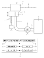
- FIG. 2 is a diagram showing a schematic configuration of the nozzle injection type glue application mechanism C and its control unit.
- the nozzle injection type glue application mechanism C includes an adhesive injection nozzle 3 that opens upward toward the lower linear path portion 1 b, a PUR glue supply source 4, and a paste from the PUR glue supply source 4.
- the body P was sprayed from the glue spray nozzle 3 while being transported along the lower linear path portion 1b (transport path) while being guided by the pair of guide plates 8a and 8b (see FIG. 1).
- PUR paste k is applied to the back of the body P.
- PUR glue is used as the binding glue, but glues other than PUR glue can also be used.
- the relationship between the thickness of the body P and the rotational speed coefficient of the pump 6 (representing the rate of increase / decrease of the rotational speed of the pump 6 with respect to the predetermined reference rotational speed of the pump 6) is specified.
- 1 function (which is a linear function in this embodiment)
- a second function (which is a linear function in this embodiment) that defines the relationship between the conveying speed of the clamper 2 and the rotational speed coefficient of the pump 6.
- the rotational speed coefficient corresponding to the thickness of the body P to be bound and the conveying speed setting value of the clamper 2 is calculated, the rotational speed setting value of the pump 6 is calculated based on the rotational speed coefficient and the reference rotational speed,
- a pump rotation speed setting unit 9 that initially sets the rotation speed of the pump 6 according to the speed setting value is provided.
- the rotational speed coefficient is the reference rotational speed of the pump 6 when the thickness of the body P takes a predetermined reference value d 0 and the transport speed of the clamper 2 takes a predetermined reference value v 0. 0 is defined as an increase / decrease rate of the rotational speed of the pump 6 when the reference rotational speed R 0 is 1.
- the pump rotation speed setting unit 9 calculates the first rotation speed coefficient K t according to the thickness of the body P to be bound using the first function, and also uses the second function.
- a second rotation speed coefficient K V corresponding to the transport speed setting value of the clamper 2 is calculated.
- the correction magnification of the first rotational speed coefficient for the thickness of two or more different bodies P and / or the correction magnification of the second rotational speed coefficient for the conveyance speed of two or more different clampers 2 are used.
- a third function (which is a linear function in this embodiment) is generated and / or after correction according to the conveyance speed of the clamper 2 based on the correction magnification of the second rotation speed coefficient input to the input unit 10
- a function generator 11 that generates a fourth function (in this embodiment, a linear function) for calculating the second rotation speed coefficient is provided.
- the correction magnification of the first and second rotational speed coefficients is expressed as a percentage (%), and when no correction is made, the correction magnification is 100%.
- the function generation unit 11 causes the third and fourth functions to be input.
- the pump rotation speed setting unit 6 calculates the corrected first rotation speed coefficient from the third function based on the thickness of the body P to be bound, and sets the conveyance speed setting value of the clamper 2 to Based on the fourth function, the corrected second rotational speed coefficient is calculated, and the rotational speed setting value of the pump 6 is calculated based on the corrected first and second rotational speed coefficients and the reference rotational speed. And the rotation speed of the pump 6 is initialized according to the calculated rotation speed setting value.
- the third function is generated by the function generation unit 11, and the pump rotation speed setting unit 9
- the first rotational speed coefficient after correction is calculated from the third function based on the thickness information of the body P to be bound, while the second function is used to calculate the second rotational speed based on the transport speed setting value of the clamper 2.
- the rotational speed coefficient is calculated, the rotational speed setting value of the pump 6 is calculated based on the calculated corrected first rotational speed coefficient, the second rotational speed coefficient, and the reference rotational speed, and the calculated rotational speed is calculated.
- the rotational speed of the pump 6 is initialized according to the set value.
- the fourth function is generated by the function generating unit 11, and the pump rotational speed setting unit 9
- the first rotation speed coefficient is calculated from the first function based on the thickness information of the body P to be bound, while the corrected second speed is calculated from the fourth function based on the transport speed setting value of the clamper 2.
- a rotation speed coefficient is calculated, a rotation speed setting value of the pump 6 is calculated based on the calculated first rotation speed coefficient, the corrected second rotation speed coefficient, and the reference rotation speed, and the calculated rotation speed is calculated.
- the rotational speed of the pump 6 is initialized according to the set value.
- the input unit 10 further receives an input of a reference value of the height of the glue injection nozzle 3 for two or more different thicknesses of the body P, and the function generator 11 receives the reference input to the input unit 10.
- a fifth function in this embodiment, a linear function
- the height setting value of the glue injection nozzle 3 is calculated based on the thickness of the body P to be bound using the fifth function, and the glue injection nozzle 3 is calculated based on the height setting value.
- an injection nozzle height setting section 12 for initially setting the height.
- the pump rotation speed setting unit 9, the input unit 10, the function generation unit 11, and the injection nozzle height setting unit 12 are incorporated in a control unit 15 that controls the entire bookbinding apparatus.
- the control unit 15 includes a display 13.
- the display 13 includes a touch panel display, and the input unit 10 includes the touch panel and a numeric keypad provided on the display 13.
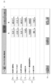
- FIG. 3 is a diagram illustrating an example of an input screen displayed on the display 13.
- the input screen is composed of a plurality of stages, and in order from the top, a first input field 16 in which a reference value for the height of glue injection nozzle 3 for two different thicknesses of body P is input.
- a second input field 17 for inputting a correction magnification of the first rotational speed coefficient of the pump 6 for two different body thicknesses, and a second input of the pump 6 for the transport speeds of the two different clampers 2
- a third input field 18 is provided for inputting the correction magnification of the rotation speed coefficient.
- the first to third input fields 16 to 18 are each divided into two stages. Then, the first thickness (5.0 mm in the illustrated example) of the body P is input to the left column (column A) of the upper part [body thickness reference point] 16a of the first input field 16, and the right side While the second thickness (40.0 mm in the illustrated example) of the body P is input to the row (B row), the left row (A of the PUR nozzle height) 16b in the lower stage of the first input field 16 (A A reference value ( ⁇ 0.6 mm in the illustrated example) of the height of the glue injection nozzle 3 with respect to the first thickness of the main body P is input to the column P), and the second value of the main body P is input to the right column (B column).
- a reference value ( ⁇ 1.0 mm) of the height of the glue spray nozzle 3 with respect to the thickness is input. It should be noted that the symbol “-” attached to the height of the glue spray nozzle 3 means a value measured downward from the position of the back of the body P.
- the first thickness (5.0 mm in the illustrated example) of the body P is input to the left column (column A) of the upper part [body thickness reference point] 17a in the second input field 17, and the right column (
- the second thickness of the body P (40.0 mm in the illustrated example) is input to the B column), while the left column (A column) of the lower [ Kt correction magnification] 17b of the second input field is input.
- a correction factor (120% in the illustrated example) of the first rotational speed coefficient with respect to the first thickness of the body P is input, and the second column with respect to the second thickness of the body P is entered in the right column (B column).
- a correction factor for the rotational speed coefficient (150% in the illustrated example) is input.
- the rotation speed of the pump 6 may be a predetermined value
- a numerical value of 100% is input as a correction magnification for the first rotation speed coefficient.
- the numerical value 100% is input to both the A column and the B column in the lower [ Kt correction magnification] 17b in the second input field, the correction magnification for the first rotational speed coefficient is not input. That is, the first rotation speed coefficient corresponding to the thickness of the body P to be bound is calculated using the first function.
- the first transport speed (1000 books / hour in the illustrated embodiment) of the clamper 2 is input to the left column (column A) of the upper [clamper transport speed reference point] 18a in the third input field 18, while the right-hand column the second conveying speed of (B column) to the clamper 2 (4000 books / h in the illustrated example) is input, the left column of the third input field of the lower [K V correction factor] 18b
- a correction magnification (90% in the illustrated example) of the second rotational speed coefficient with respect to the first transport speed of the clamper 2 is input to (A column), and the second transport of the clamper 2 is to the right column (B column).
- a correction magnification (150% in the illustrated example) of the second rotational speed coefficient with respect to the speed is input.
- the rotation speed of the pump 6 may be a predetermined value
- a numerical value of 100% is input as a correction magnification for the second rotation speed coefficient.
- the third lower [K V Correction factor] 18b numerical 100% in both the A column and the B column of the input field is inputted, the input of the correction factor of the second rotation speed coefficient was not made
- the second rotation speed coefficient corresponding to the transport speed setting value of the clamper 2 is calculated using the second function.
- the function generator 11 When numerical values are input to the input fields 16 to 18 on the screen and the return key 19 displayed at the lower left of the input screen is pressed, those numerical values are input to the input unit 10. Then, the function generator 11 generates the third to fifth functions based on the numerical value input to the input unit 10.
- a switching tab 20 (indicated by numbers “1” to “3”) for switching the input screen area is provided in the upper part of the input screen. Then, by switching the switching tab 20, a plurality of sets of numerical values (three sets in this embodiment) can be input to the input unit 9. Further, the control unit 15 includes a memory 14, and a plurality of sets of numerical values are stored in the memory 14.
- the function generation unit 11 generates a function using the input set of numerical values. As a result, the input operation by the user can be performed easily and in a short time.
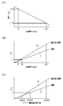
- FIG. 4A is a diagram illustrating a graph of the fifth function.
- the vertical axis represents the height (mm) of the glue injection nozzle 3
- the horizontal axis represents the thickness (mm) of the body P.
- the sign “ ⁇ ” is attached to the height of the glue spray nozzle 3, which means that the value is measured downward from the position of the back of the body P.
- the reference values ( ⁇ 0.6 mm, ⁇ 1.0 mm) of the height of the glue injection nozzle 3 with respect to the thicknesses (5 mm, 40 mm) of two different main bodies P are input units.
- the function generator 11 generates a fifth function based on the reference values of the heights of the glue injection nozzles 3 corresponding to the thicknesses of the two main bodies P.
- the fifth function is generated by setting an XY coordinate system in which the thickness of the body P is the X axis and the height of the glue injection nozzle 3 is the Y axis, and points A (5 mm, ⁇ 0.6 mm) and B This is done by deriving a linear equation through (40 mm, -1.0 mm).
- FIG. 4B is a diagram illustrating a graph of the first and third functions.
- the vertical axis represents the first rotation speed coefficient K t
- the horizontal axis represents the thickness of the book block P (mm)
- linear I is the first function
- linear III Part 3 function the scale of the vertical axis of the graph, as the reference rotational speed R 0 the rotational speed of the pump 6 when the thickness of the book block P is 10 mm, the value of the proportion of time that the standard rotational speed R 0 and 1.
- two different book block thickness of the P (10 mm, 40 mm) correction factor (120%, 150%) of the first rotational speed coefficient K t for input to the input unit 10 is (see FIG. 3), the function generator 11, the third function III is generated based on the their two correction magnification of the first rotation speed coefficient K t corresponding to the thickness of the book block P.
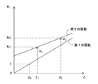
- FIG. 5 is a graph for explaining a generation process of the third function III in the function generation unit 11.
- the vertical axis represents the first rotation speed coefficient K t
- the horizontal axis represents the thickness d of the body P.
- FIG. 4C is a diagram illustrating a graph of the second and fourth functions.
- the vertical axis represents the second rotational speed coefficient K V
- the horizontal axis represents the conveying speed of the clamper 2 (Saku / hr)
- also straight II is the second function
- Line IV is the fourth function.
- the scale of the vertical axis of the graph is a ratio value when the rotation speed of the pump 6 when the conveying speed of the clamper 2 is 2000 volumes / hour is the reference rotation speed R 0 and the reference rotation speed R 0 is 1. It is.
- first to fifth functions generated by the function generator 11 are not limited to this embodiment, and may be any appropriate function other than the linear function.
- Information on the thickness of the body P to be bound is obtained by measurement by a known body thickness measuring unit (not shown) attached to the bookbinding apparatus or provided separately from the bookbinding apparatus, and this measured value is controlled. This is received by the unit 15. Further, the conveyance speed of the clamper 2 is the one input to the control unit 15 at the initial setting of the bookbinding apparatus.
- the first function that defines the relationship between the thickness of the body and the rotational speed coefficient of the pump and the second function that defines the relationship between the transport speed of the clamper and the rotational speed coefficient of the pump.
- the rotation speed setting value of the pump is calculated based on the rotation speed coefficient and the reference rotation speed. Since the pump rotation speed is automatically initialized according to the rotation speed setting value, the initial setting work of the nozzle injection type glue application mechanism can be done easily and in a short time, greatly reducing the work burden on the user. Is done.
- the function generation unit 11 calculates the third rotation speed coefficient after correction according to the thickness of the body P. And / or a fourth function for calculating a corrected second rotational speed coefficient according to the transport speed of the clamper 2 is generated.
- the pump rotation speed setting unit 9 calculates the first rotation speed coefficient after correction according to the thickness of the body P to be bound by using the third function, and / or Using the fourth function, a corrected second rotation speed coefficient corresponding to the transport speed setting value of the clamper 2 is calculated, and the calculated first and / or second rotation speed coefficient after correction is used.
- the rotational speed set value of the pump 6 is calculated, and the rotational speed of the pump is automatically initialized according to the rotational speed set value.
- the setting value of the height of the glue injection nozzle 3 corresponding to the thickness of the main body P to be bound is calculated by the injection nozzle height setting unit 12 using the fifth function. According to the value, the height of the glue injection nozzle 3 is initialized.
- the initial setting work of the nozzle jet type glue application mechanism C can be performed easily and in a short time, and the work burden on the user is greatly reduced.
- the initial settings for the clamper 2, the milling unit B, the horizontal glue unit D, the cover attaching unit E, and the cover supply unit F are made at the same time as the initial setting of the nozzle jetting glue application mechanism C.
- the clamper 2 takes the open position, and the body P is placed with the back facing downward by the body supply unit (not shown). Is supplied to the clamper 2, and then the clamper 2 takes the closed position, whereby the body P is clamped by the clamper 2.
- the clamper 2 leaves the body insertion position A and moves toward the milling unit B, and the back surface of the body P is cut while the body P sandwiched by the clamper 2 passes over the milling unit B.
- the main body P sandwiched between the clampers 2 is sent to the nozzle injection type glue application mechanism C.
- the paste P is ejected from the paste injection nozzle 3 to the back of the body P.
- PUR glue is applied in a predetermined thickness
- the body P sandwiched between the clampers 2 is sent to the cover attaching unit E via the horizontal glue unit D.
- a cover is pasted on the back of the body P to complete the bookbinding product P ′.
- the bookbinding product P ′ reaches the body insertion position A through the arcuate path portion 1c, the upper linear path portion 1a, and the arcuate path portion 1d while being sandwiched by the clamper 2, and stops.
- the clamper 2 takes the open position, and the bookbinding product P ′ falls onto the bookbinding product discharge unit G and is conveyed outside the bookbinding apparatus.
- the configuration of the present invention has been described based on the preferred embodiments.
- the configuration of the present invention is not limited to the above-described embodiments, and can be arbitrarily set within the scope of the configurations described in the claims appended hereto.
- the rotational speed of the pump 6 is adjusted according to the thickness of the body P to be bound and the conveyance speed setting value of the clamper 2, and the thickness of the body P to be bound is adjusted.
- the height of the glue injection nozzle 3 is adjusted, but instead, only the rotational speed of the pump 6 is adjusted only in accordance with the thickness of the body P at the initial setting. It may be.
- the input unit 10 receives only the input of the correction magnification of the first rotation speed coefficient of the pump 6, the function generation unit 11 generates only the third function, and the pump rotation speed setting unit 9
- the corrected first rotation speed coefficient is calculated from the third function based on the thickness of the body P to be bound.
- the rotational speed setting value of the pump 6 is calculated based on the reference rotational speed and the corrected first rotational speed coefficient, and the rotational speed of the pump 6 is initialized according to the calculated rotational speed setting value.
- only the rotational speed of the pump 6 may be adjusted according to only the conveying speed of the clamper 2 at the initial setting.
- the input unit 10 receives only the input of the correction magnification of the second rotation speed coefficient of the pump 6, the function generation unit 11 generates only the fourth function, and the pump rotation speed setting unit 12
- the corrected second rotational speed coefficient is calculated from the fourth function based on the transport speed setting value of the clamper 2.
- the rotation speed setting value of the pump 6 is calculated based on the reference rotation speed and the corrected second rotation speed coefficient, and the rotation speed of the pump 6 is initialized using the calculated rotation speed setting value.
- the height of the glue injection nozzle 3 is adjusted according to the thickness of the main body P to be bound at the time of initial setting, but this configuration is provided as necessary. That's fine.
- the rotational speed of the pump 6 is initialized according to the set value of the height of the glue injection nozzle 3 in addition to the thickness of the body P to be bound and the transport speed setting of the clamper 2. It can also be set as such a structure.
- the pump rotation speed setting unit 9 calculates a first rotation speed coefficient corresponding to the thickness of the body P to be bound using the first function, and according to the conveyance speed setting value of the clamper 2.
- the third rotation speed represents the increase / decrease rate of the rotation speed with reference to the height of the glue injection nozzle 3 and the reference rotation speed of the pump 6 as a reference rotation speed.
- a third rotation speed coefficient corresponding to the set value of the height of the glue injection nozzle 3 is also calculated using a sixth function that defines the relationship with the coefficient, and the calculated first to third rotation speed coefficients Based on the reference rotational speed of the pump 6, a rotational speed set value of the pump 6 is calculated, and the rotational speed of the pump 6 is initialized according to the rotational speed set value.
- the input unit 10 has a first rotation speed coefficient correction magnification for two different body P thicknesses, and a second rotation speed coefficient correction magnification for two different clamper 2 conveyance speeds, And the correction magnification of the third rotational speed coefficient for the heights of the two different paste injection nozzles 3 can be received.
- the function generating unit 11 calculates not only the third and fourth functions but also the corrected third rotational speed coefficient corresponding to the height of the paste injection nozzle 3 based on the correction magnification of the third rotational speed coefficient. A seventh function for calculation is also generated.
- FIG. 6 is a diagram illustrating graphs of the sixth and seventh functions.
- the vertical axis represents the third rotation speed coefficient K h
- the horizontal axis represents the height of the glue injection nozzle 3 (mm)
- linear VI is a function of the sixth straight VII Is the seventh function.
- the scale on the vertical axis of the graph indicates the ratio when the rotational speed of the pump 6 when the height of the glue injection nozzle 3 is ⁇ 0.5 mm is the reference rotational speed R 0 and the reference rotational speed R 0 is 1. Is the value of
- the pump rotational speed setting unit 9 sets the thickness of the body P to be bound when the correction magnifications of the first to third rotational speed coefficients are input to the input unit 10 before starting the bookbinding.
- the corrected first rotation speed coefficient is calculated, and based on the transport speed setting value of the clamper 2, the corrected second rotation speed coefficient is calculated from the fourth function.
- a third rotational speed coefficient after correction is calculated from the seventh function, and the corrected first through third rotational speed coefficients and the reference rotational speed are calculated.
- the rotational speed set value of the pump 6 is calculated based on the above, and the rotational speed of the pump 6 is initialized according to the calculated rotational speed set value.
Abstract
本身Pの厚さと、ポンプ6の所定の基準回転速度を基準としたポンプの回転速度の増減率を表す回転速度係数との関係を規定する第1の関数、およびクランパの搬送速度とポンプの回転速度係数との関係を規定する第2の関数を用いて、製本すべき本身の厚さおよびクランパの搬送速度設定値に応じた回転速度係数を算出し、算出した回転速度係数および基準回転速度に基づいてポンプの回転速度設定値を算出し、回転速度設定値に従ってポンプの回転速度を初期設定するポンプ回転速度設定部9を備える。
Description
本発明は、製本装置、特に、ノズル噴射式糊塗布機構を備えた無線綴じ製本装置に関するものである。
無線綴じ製本においては、これまで、EVA(Ethylene Vinyl Acetate)系ホットメルト糊(以下、「EVA糊」という。)を使用するのが一般的であったが、EVA糊は、加熱されると溶融し、冷やされると硬化する、というサイクルを無限に繰り返すので、取り扱いが容易である反面、接着力が劣るという欠点を有していた。
そこで、近年では、EVA糊に比べて接着力が格段に強いPUR(Poly Urethane Reactive)系ホットメルト糊(以下、「PUR糊」という。)が注目されているが、PUR糊は、空気中や用紙中の水分と反応して硬化し、一度硬化すると熱を加えても軟化しないという特性を有している。
そのため、PUR糊を用いる製本装置においては、このPUR糊の特性に適した糊塗布機構が必要とされる。
すなわち、同一の製本物を大量生産する場合は、EVA糊を用いる製本装置と同様に、ローラ式糊塗布機構が備えられ、クランパに起立状態で挟持された本身が搬送路上を搬送される間に、本身の背に糊塗布ローラによってPUR糊が塗布される。
すなわち、同一の製本物を大量生産する場合は、EVA糊を用いる製本装置と同様に、ローラ式糊塗布機構が備えられ、クランパに起立状態で挟持された本身が搬送路上を搬送される間に、本身の背に糊塗布ローラによってPUR糊が塗布される。
これに対し、多品種の製本物を少量生産する場合には、ローラ式糊塗布機構よりもむしろノズル噴射式糊塗布機構が備えられ、ノズルから糊を本身の背に噴射することでPUR糊の塗布がなされる(例えば、特許文献1参照)。
ノズル噴射式糊塗布機構は、本身の搬送路に向けて開口した糊噴射ノズルと、糊供給源と、糊供給源から糊噴射ノズルに糊を供給するための糊供給管と、糊供給管に設けられたポンプを備えていて、本身がクランパに挟持されて搬送路に沿って搬送される間に、糊噴射ノズルから噴射された糊が本身の背に塗布されるようになっている。
ところで、本身の厚さに応じて本身の背に塗布すべき糊の量が変化するので、ノズル噴射式糊塗布機構においては、ポンプの回転速度を変化させて糊噴射ノズルに送る糊の量を制御する必要があるが、糊噴射ノズルに送る糊の量が同じでも、クランパの搬送速度が変化すると、本身の背に塗布される糊の厚さも変化する。
したがって、ポンプの回転速度の制御は、本身の厚さだけでなくクランパの搬送速度も考慮に入れて行わねばならない。
したがって、ポンプの回転速度の制御は、本身の厚さだけでなくクランパの搬送速度も考慮に入れて行わねばならない。
また、本身を形成する用紙または折丁の紙質や紙厚等は様々であり、また糊の種類が異なるとその糊質も異なるので、本身の背に塗布すべき糊の厚さは、本身の厚さだけでなく、それらの条件も考慮して決定する必要がある。
さらには、製本物の外観の評価は主観的であってユーザー毎に異なるから、ユーザーの好みに合った製本の仕上がりが得られるように、本身の背に塗布すべき糊の厚さを設定したい場合がある。
さらには、製本物の外観の評価は主観的であってユーザー毎に異なるから、ユーザーの好みに合った製本の仕上がりが得られるように、本身の背に塗布すべき糊の厚さを設定したい場合がある。
そのため、通常は、製本の開始前に、ユーザーが、予め実施した製本テストの結果に基づき作成したポンプの回転速度値の表に基づいて、ノズル噴射式糊塗布機構のポンプの回転速度を初期設定している。
しかしながら、この表の作成作業は、本身の厚さ、ポンプの回転速度およびクランパの搬送速度等の組み合わせを様々に変化させながら、実際に製本を行うことでなされ、長時間と多くの労力を要しており、ユーザーにとっては大きな負担となっていた。
しかしながら、この表の作成作業は、本身の厚さ、ポンプの回転速度およびクランパの搬送速度等の組み合わせを様々に変化させながら、実際に製本を行うことでなされ、長時間と多くの労力を要しており、ユーザーにとっては大きな負担となっていた。
したがって、本発明の課題は、製本装置のノズル噴射式糊塗布機構の初期設定が簡単かつ迅速に行えるようにすることにある。
上記課題を解決するため、本発明によれば、本身の搬送路の下側に配置されたノズル噴射式糊塗布機構と、前記本身を起立状態で挟持して前記搬送路に沿って搬送するクランパとを備え、前記ノズル噴射式糊塗布機構は、前記搬送路に向けて開口した糊噴射ノズルと、糊供給源と、前記糊供給源から前記糊噴射ノズルに糊を供給するための糊供給管と、前記糊供給管に設けられたポンプと、を有し、前記本身が前記搬送路に沿って搬送される間に、前記糊噴射ノズルから噴射された糊が前記本身の背に塗布される製本装置において、前記本身の厚さと、前記ポンプの所定の基準回転速度を基準とした前記ポンプの回転速度の増減率を表す回転速度係数との関係を規定する第1の関数、および前記クランパの搬送速度と前記回転速度係数との関係を規定する第2の関数を用いて、製本すべき前記本身の厚さおよび前記クランパの搬送速度設定値に応じた前記回転速度係数を算出し、前記算出した回転速度係数および前記基準回転速度に基づいて前記ポンプの回転速度設定値を算出し、前記回転速度設定値に従って前記ポンプの回転速度を初期設定するポンプ回転速度設定部を備えたものであることを特徴とする製本装置が提供される。
本発明の好ましい実施例によれば、前記製本装置は、さらに、2以上の異なる前記本身の厚さに対する前記回転速度係数の補正倍率の入力を受け得る入力部と、前記入力部に入力された前記回転速度係数の補正倍率に基づき、前記第1の関数に代わる、前記本身の厚さに応じた補正後の前記回転速度係数を算出するための第3の関数を生成する関数生成部と、を備え、前記ポンプ回転速度設定部が、製本開始前、前記入力部に前記回転速度係数の補正倍率が入力されたときは、前記第3の関数を用いて製本すべき前記本身の厚さに応じた前記補正後の回転速度係数を算出し、当該補正後の回転速度係数と、前記第2の関数を用いて算出した前記クランパの搬送速度設定値に応じた前記回転速度係数と、前記基準回転速度とに基づいて前記ポンプの回転速度設定値を算出するようになっている。
本発明の別の好ましい実施例によれば、前記製本装置は、さらに、2以上の異なる前記クランパの搬送速度に対する前記回転速度係数の補正倍率の入力を受け得る入力部と、前記入力部に入力された前記回転速度係数の補正倍率に基づき、前記第2の関数に代わる、前記クランパの搬送速度に応じた補正後の前記回転速度係数を算出するための第4の関数を生成する関数生成部と、を備え、前記ポンプ回転速度設定部が、製本開始前、前記入力部に前記回転速度係数の補正倍率が入力されたときは、前記第4の関数を用いて前記クランパの搬送速度設定値に応じた前記補正後の回転速度係数を算出し、当該補正後の回転速度係数と、前記第1の関数を用いて算出した製本すべき前記本身の厚さに応じた前記回転速度係数と、前記基準回転速度とに基づいて前記ポンプの回転速度設定値を算出するようになっている。
本発明のさらに別の好ましい実施例によれば、前記製本装置は、さらに、2以上の異なる前記本身の厚さに対する前記回転速度係数の第1の補正倍率、および2以上の異なる前記クランパの搬送速度に対する前記回転速度係数の第2の補正倍率の入力を受け得る入力部と、前記入力部に入力された前記第1の補正倍率に基づき、前記第1の関数に代わる、前記本身の厚さに応じた第1の補正後の前記回転速度係数を算出するための第3の関数を生成するとともに、前記入力部に入力された前記第2の補正倍率に基づき、前記第2の関数に代わる、前記クランパの搬送速度に応じた第2の補正後の前記回転速度係数を算出するための第4の関数を生成する関数生成部と、を備え、前記ポンプ回転速度設定部が、製本開始前、前記入力部に前記第1および第2の補正倍率が入力されたときは、前記第3の関数を用いて製本すべき前記本身の厚さに応じた前記第1の補正後の回転速度係数を算出するとともに、前記第4の関数を用いて前記クランパの搬送速度設定値に応じた前記第2の補正後の回転速度係数を算出し、当該第1および第2の補正後の回転速度係数と、前記基準回転速度とに基づいて前記ポンプの回転速度設定値を算出するようになっている。
本発明によれば、本身の厚さとポンプの回転速度係数(ポンプの所定の基準回転速度を基準としたポンプの回転速度の増減率を表す)との関係を規定する第1の関数と、クランパの搬送速度とポンプの回転速度係数との関係を規定する第2の関数とを用いて、製本すべき本身の厚さおよびクランパの搬送速度設定値に応じた回転速度係数を算出し、当該回転速度係数および基準回転速度に基づいてポンプの回転速度設定値を算出し、当該回転速度設定値に従ってポンプの回転速度を自動的に初期設定するので、ノズル噴射式糊塗布機構の初期設定作業が簡単にかつ短時間で行えるようになり、ユーザーの作業負担が大幅に低減される。
以下、添付図面を参照しつつ、本発明の構成を好ましい実施例に基づいて説明する。
図1は、本発明の1実施例による製本装置の概略構成を示す斜視図である。
図1を参照して、本発明によれば、本身Pを起立状態に挟持し、予め設定された経路1に沿って移動可能に配置された1または2以上(この実施例では、4つ)のクランパ2が備えられる。
図1は、本発明の1実施例による製本装置の概略構成を示す斜視図である。
図1を参照して、本発明によれば、本身Pを起立状態に挟持し、予め設定された経路1に沿って移動可能に配置された1または2以上(この実施例では、4つ)のクランパ2が備えられる。
この実施例では、クランパ2の経路1は、垂直面内において間隔をあけて配置された水平な上側および下側直線状経路部分1a、1bと、上側および下側直線状経路部分1a、1bの端同士を接続する弧状経路部分1c、1dとからなるループ状をなしている。
また、図示はしないが、経路1に沿って適当なガイドが設けられている。そして、クランパ2は、このガイドに対してスライド可能に取り付けられ、ガイドによって案内されつつ経路1に沿って移動し得る。
クランパ2は、公知の適当な駆動機構(図示はしない)によって、経路1に沿って一方向(図1では反時計回り)に移動するようになっている。
また、図示はしないが、経路1に沿って適当なガイドが設けられている。そして、クランパ2は、このガイドに対してスライド可能に取り付けられ、ガイドによって案内されつつ経路1に沿って移動し得る。
クランパ2は、公知の適当な駆動機構(図示はしない)によって、経路1に沿って一方向(図1では反時計回り)に移動するようになっている。
本発明によれば、また、下側直線状経路部分1bに沿って、ミリングユニットB、ノズル噴射式糊塗布機構C、横糊ユニットDおよび表紙付けユニットEが配置される。なお、図1中、Fは、表紙付けユニットEに表紙gを供給する表紙供給ユニットである。
また、下側直線状経路部分1bにおけるミリングユニットBの上流側に本身供給位置Aが設けられる。本身供給位置Aは製本物排出位置も兼ねている。
また、下側直線状経路部分1bにおけるミリングユニットBの上流側に本身供給位置Aが設けられる。本身供給位置Aは製本物排出位置も兼ねている。
図2は、ノズル噴射式糊塗布機構Cとその制御部の概略構成を示す図である。
図2に示すように、ノズル噴射式糊塗布機構Cは、上向きに下側直線状経路部分1bに向けて開口した糊噴射ノズル3と、PUR糊供給源4と、PUR糊供給源4から糊噴射ノズル3にPUR糊を供給するための糊供給管5と、糊供給管5に設けられて糊噴射ノズル3にPUR糊を送るポンプ6と、糊噴射ノズル3を昇降させ得るノズル高さ調節機構7ととを有している。
図2に示すように、ノズル噴射式糊塗布機構Cは、上向きに下側直線状経路部分1bに向けて開口した糊噴射ノズル3と、PUR糊供給源4と、PUR糊供給源4から糊噴射ノズル3にPUR糊を供給するための糊供給管5と、糊供給管5に設けられて糊噴射ノズル3にPUR糊を送るポンプ6と、糊噴射ノズル3を昇降させ得るノズル高さ調節機構7ととを有している。
そして、本身Pが、一対のガイド板8a、8b(図1参照)によって案内されつつ下側直線状経路部分1b(搬送路)に沿って搬送される間に、糊噴射ノズル3から噴射されたPUR糊kが本身Pの背に塗布されるようになっている。
なお、この実施例では、製本用の糊としてPUR糊が使用されるが、PUR糊以外の糊を使用することもできる。
なお、この実施例では、製本用の糊としてPUR糊が使用されるが、PUR糊以外の糊を使用することもできる。
本発明によれば、また、本身Pの厚さとポンプ6の回転速度係数(ポンプ6の所定の基準回転速度を基準としたポンプ6の回転速度の増減率を表す)との関係を規定する第1の関数(この実施例では一次関数である)、およびクランパ2の搬送速度とポンプ6の回転速度係数との関係を規定する第2の関数(この実施例では一次関数である)を用いて、製本すべき本身Pの厚さおよびクランパ2の搬送速度設定値に応じた回転速度係数を算出し、当該回転速度係数および基準回転速度に基づいてポンプ6の回転速度設定値を算出し、回転速度設定値に従ってポンプ6の回転速度を初期設定するポンプ回転速度設定部9が備えられる。
このポンプ回転速度設定部9によるポンプ6の回転速度設定値の算出は、具体的には次のようにしてなされる。
この実施例では、回転速度係数は、本身Pの厚さが所定の基準値d0をとり、かつクランパ2の搬送速度が所定の基準値v0をとるときのポンプ6の基準回転速度をR0として、基準回転速度R0を1としたときのポンプ6の回転速度の増減率として規定される。
そして、ポンプ回転速度設定部9において、第1の関数を用いて、製本すべき本身Pの厚さに応じた第1の回転速度係数Ktが算出され、また、第2の関数を用いて、クランパ2の搬送速度設定値に応じた第2の回転速度係数KVが算出される。
次いで、第1および第2の回転速度係数KtおよびKVを用いて、ポンプの回転速度設定値Rが、
R=R0×Kt×KV
によって算出される。
この実施例では、回転速度係数は、本身Pの厚さが所定の基準値d0をとり、かつクランパ2の搬送速度が所定の基準値v0をとるときのポンプ6の基準回転速度をR0として、基準回転速度R0を1としたときのポンプ6の回転速度の増減率として規定される。
そして、ポンプ回転速度設定部9において、第1の関数を用いて、製本すべき本身Pの厚さに応じた第1の回転速度係数Ktが算出され、また、第2の関数を用いて、クランパ2の搬送速度設定値に応じた第2の回転速度係数KVが算出される。
次いで、第1および第2の回転速度係数KtおよびKVを用いて、ポンプの回転速度設定値Rが、
R=R0×Kt×KV
によって算出される。
また、本発明によれば、2以上の異なる本身Pの厚さに対する第1の回転速度係数の補正倍率、および/または2以上の異なるクランパ2の搬送速度に対する第2の回転速度係数の補正倍率の入力を受け得る入力部10と、入力部10に入力された第1の回転速度係数の補正倍率に基づき本身Pの厚さに応じた補正後の第1の回転速度係数を算出するための第3の関数(この実施例では一次関数である)を生成し、および/または入力部10に入力された第2の回転速度係数の補正倍率に基づきクランパ2の搬送速度に応じた補正後の第2の回転速度係数を算出するための第4の関数(この実施例では一次関数である)を生成する関数生成部11が備えられる。
この場合、第1および第2の回転速度係数の補正倍率は百分率(%)で表され、補正なしのとき、補正倍率は100%となる。
この場合、第1および第2の回転速度係数の補正倍率は百分率(%)で表され、補正なしのとき、補正倍率は100%となる。
こうして、例えば、製本開始前、入力部10に第1の回転速度係数の補正倍率および第2の回転速度係数の補正倍率が入力されたときは、関数生成部11によって第3および第4の関数が生成され、ポンプ回転速度設定部6は、製本すべき本身Pの厚さに基づいて第3の関数から補正後の第1の回転速度係数を算出するとともに、クランパ2の搬送速度設定値に基づいて第4の関数から補正後の第2の回転速度係数を算出し、算出した補正後の第1のおよび第2の回転速度係数と基準回転速度とに基づいてポンプ6の回転速度設定値を算出し、算出した回転速度設定値に従ってポンプ6の回転速度を初期設定する。
また、例えば、製本開始前、入力部10に第1の回転速度係数の補正倍率のみが入力されたときは、関数生成部11によって第3の関数のみが生成され、ポンプ回転速度設定部9は、製本すべき本身Pの厚さ情報に基づいて第3の関数から補正後の第1の回転速度係数を算出する一方、クランパ2の搬送速度設定値に基づいて第2の関数から第2の回転速度係数を算出し、算出した補正後の第1の回転速度係数と、第2の回転速度係数と、基準回転速度とに基づいてポンプ6の回転速度設定値を算出し、算出した回転速度設定値に従ってポンプ6の回転速度を初期設定する。
また、例えば、製本開始前、入力部10に第2の回転速度係数の補正倍率のみが入力されたときは、関数生成部11によって第4の関数のみが生成され、ポンプ回転速度設定部9は、製本すべき本身Pの厚さ情報に基づいて第1の関数から第1の回転速度係数を算出する一方、クランパ2の搬送速度設定値に基づいて第4の関数から補正後の第2の回転速度係数を算出し、算出した第1の回転速度係数と、補正後の第2の回転速度係数と、基準回転速度とに基づいてポンプ6の回転速度設定値を算出し、算出した回転速度設定値に従ってポンプ6の回転速度を初期設定する。
この実施例では、さらに、入力部10が2以上の異なる本身Pの厚さに対する糊噴射ノズル3の高さの基準値の入力を受け、関数生成部11は、入力部10に入力された基準値に基づき、本身Pの厚さに応じた糊噴射ノズル3の高さの設定値を算出するための第5の関数(この実施例では一次関数)を生成するようになっている。
また、この実施例では、第5の関数を用いて、製本すべき本身Pの厚さに基づき、糊噴射ノズル3の高さ設定値を算出し、高さ設定値に基づいて糊噴射ノズル3の高さを初期設定する噴射ノズル高さ設定部12が備えられる。
また、この実施例では、第5の関数を用いて、製本すべき本身Pの厚さに基づき、糊噴射ノズル3の高さ設定値を算出し、高さ設定値に基づいて糊噴射ノズル3の高さを初期設定する噴射ノズル高さ設定部12が備えられる。
ポンプ回転速度設定部9、入力部10、関数生成部11および噴射ノズル高さ設定部12は、製本装置の全体を制御する制御部15に組み込まれている。
制御部15は、ディスプレイ13を備えている。ディスプレイ13は、タッチパネルディスプレイからなっており、入力部10は、このタッチパネルと、ディスプレイ13に併設されたテンキーを有している。
制御部15は、ディスプレイ13を備えている。ディスプレイ13は、タッチパネルディスプレイからなっており、入力部10は、このタッチパネルと、ディスプレイ13に併設されたテンキーを有している。
図3は、ディスプレイ13に表示される入力画面の一例を示す図である。
図3を参照して、入力画面は、複数段から構成され、上から順に、2つの異なる本身Pの厚さに対する糊噴射ノズル3の高さの基準値が入力される第1の入力欄16と、2つ異なるの本身の厚さに対するポンプ6の第1の回転速度係数の補正倍率が入力される第2の入力欄17と、2つの異なるクランパ2の搬送速度に対するポンプ6の第2の回転速度係数の補正倍率が入力される第3の入力欄18を有している。
図3を参照して、入力画面は、複数段から構成され、上から順に、2つの異なる本身Pの厚さに対する糊噴射ノズル3の高さの基準値が入力される第1の入力欄16と、2つ異なるの本身の厚さに対するポンプ6の第1の回転速度係数の補正倍率が入力される第2の入力欄17と、2つの異なるクランパ2の搬送速度に対するポンプ6の第2の回転速度係数の補正倍率が入力される第3の入力欄18を有している。
第1~第3の入力欄16~18はそれぞれ2段に分かれている。
そして、第1の入力欄16の上段[本身厚さ基準点]16aの左側の列(A列)に本身Pの第1の厚さ(図示の例では5.0mm)が入力され、右側の列(B列)に本身Pの第2の厚さ(図示の例では40.0mm)が入力される一方、第1の入力欄16の下段[PURノズル高さ]16bの左側の列(A列)に本身Pの第1の厚さに対する糊噴射ノズル3の高さの基準値(図示の例では-0.6mm)が入力され、右側の列(B列)に本身Pの第2の厚さに対する糊噴射ノズル3の高さの基準値(-1.0mm)が入力される。
なお、糊噴射ノズル3の高さに”-”記号を付しているのは、本身Pの背の位置から下向きに測った値であることを意味している。
そして、第1の入力欄16の上段[本身厚さ基準点]16aの左側の列(A列)に本身Pの第1の厚さ(図示の例では5.0mm)が入力され、右側の列(B列)に本身Pの第2の厚さ(図示の例では40.0mm)が入力される一方、第1の入力欄16の下段[PURノズル高さ]16bの左側の列(A列)に本身Pの第1の厚さに対する糊噴射ノズル3の高さの基準値(図示の例では-0.6mm)が入力され、右側の列(B列)に本身Pの第2の厚さに対する糊噴射ノズル3の高さの基準値(-1.0mm)が入力される。
なお、糊噴射ノズル3の高さに”-”記号を付しているのは、本身Pの背の位置から下向きに測った値であることを意味している。
第2の入力欄17の上段[本身厚さ基準点]17aの左側の列(A列)に本身Pの第1の厚さ(図示の例では5.0mm)が入力され、右側の列(B列)に本身Pの第2の厚さ(図示の例では40.0mm)が入力される一方、第2の入力欄の下段[Kt補正倍率]17bの左側の列(A列)に本身Pの第1の厚さに対する第1の回転速度係数の補正倍率(図示の例では120%)が入力され、右側の列(B列)に本身Pの第2の厚さに対する第2の回転速度係数の補正倍率(図示の例では150%)が入力される。
なお、ポンプ6の回転速度が既定値のままでよい場合は、第1の回転速度係数の補正倍率として数値100%が入力される。そして、第2の入力欄の下段[Kt補正倍率]17bのA列およびB列の両方に数値100%が入力された場合は、第1の回転速度係数の補正倍率の入力はなされなかったことになり、製本すべき本身Pの厚さに応じた第1の回転速度係数は第1の関数を用いて算出される。
なお、ポンプ6の回転速度が既定値のままでよい場合は、第1の回転速度係数の補正倍率として数値100%が入力される。そして、第2の入力欄の下段[Kt補正倍率]17bのA列およびB列の両方に数値100%が入力された場合は、第1の回転速度係数の補正倍率の入力はなされなかったことになり、製本すべき本身Pの厚さに応じた第1の回転速度係数は第1の関数を用いて算出される。
また、第3の入力欄18の上段[クランパ搬送速度基準点]18aの左側の列(A列)にクランパ2の第1の搬送速度(図示の実施例では1000冊/時)が入力され、右側の列(B列)にクランパ2の第2の搬送速度(図示の例では4000冊/時)が入力される一方、第3の入力欄の下段[KV補正倍率]18bの左側の列(A列)にクランパ2の第1の搬送速度に対する第2の回転速度係数の補正倍率(図示の例では90%)が入力され、右側の列(B列)にクランパ2の第2の搬送速度に対する第2の回転速度係数の補正倍率(図示の例では150%)が入力される。
なお、ポンプ6の回転速度が既定値のままでよい場合は、第2の回転速度係数の補正倍率として数値100%が入力される。そして、第3の入力欄の下段[KV補正倍率]18bのA列およびB列の両方に数値100%が入力された場合は、第2の回転速度係数の補正倍率の入力はなされなかったことになり、クランパ2の搬送速度設定値に応じた第2の回転速度係数は第2の関数を用いて算出される。
なお、ポンプ6の回転速度が既定値のままでよい場合は、第2の回転速度係数の補正倍率として数値100%が入力される。そして、第3の入力欄の下段[KV補正倍率]18bのA列およびB列の両方に数値100%が入力された場合は、第2の回転速度係数の補正倍率の入力はなされなかったことになり、クランパ2の搬送速度設定値に応じた第2の回転速度係数は第2の関数を用いて算出される。
画面上の各入力欄16~18に数値が入力され、入力画面左下に表示されたリターンキー19が押されたとき、それらの数値が入力部10に入力される。
そして、関数生成部11において、入力部10に入力された数値に基づいて第3~第5の関数が生成される。
そして、関数生成部11において、入力部10に入力された数値に基づいて第3~第5の関数が生成される。
この実施例では、さらに、図3に示すように、入力画面の上段に、入力画面領域を切り替えるための切替タブ20(番号”1”~”3”で示す)が設けられている。そして、切替タブ20の切り替えによって、入力部9に数値の組が複数組(この実施例では3組)入力可能になっている。
また、制御部15はメモリ14を備えており、これら複数組の数値がメモリ14に格納される。
また、制御部15はメモリ14を備えており、これら複数組の数値がメモリ14に格納される。
そして、入力画面の切替タブ20の選択によって、数値の複数の組のうちの1つの組が選択され、次いで、リターンキー19が押されることによって当該数値の組が入力部9に入力される。入力された1組の数値を用いて、関数生成部11が関数を生成する。
それによって、ユーザーによる入力作業がより容易にかつ短時間で行えるようになる。
それによって、ユーザーによる入力作業がより容易にかつ短時間で行えるようになる。
次に、関数生成部11による関数の生成の詳細を図面を参照しつつ説明する。
図4Aは、第5の関数のグラフを例示した図である。図4Aのグラフ中、縦軸は糊噴射ノズル3の高さ(mm)を表し、横軸は本身Pの厚さ(mm)を表している。ここで、糊噴射ノズル3の高さに”-”記号を付しているのは、本身Pの背の位置から下向きに測った値であることを意味している。
図4Aは、第5の関数のグラフを例示した図である。図4Aのグラフ中、縦軸は糊噴射ノズル3の高さ(mm)を表し、横軸は本身Pの厚さ(mm)を表している。ここで、糊噴射ノズル3の高さに”-”記号を付しているのは、本身Pの背の位置から下向きに測った値であることを意味している。
図4Aを参照して、この実施例では、異なる2つの本身Pの厚さ(5mm、40mm)に対する糊噴射ノズル3の高さの基準値(-0.6mm、-1.0mm)が入力部10に入力され(図3参照)、関数生成部11において、それら2つの本身Pの厚さと対応する糊噴射ノズル3の高さの基準値に基づいて第5の関数が生成される。
第5の関数の生成は、本身Pの厚さをX軸とし、糊噴射ノズル3の高さをY軸とするXY座標系を設定し、点A(5mm、-0.6mm)、点B(40mm、-1.0mm)を通る直線の方程式を導出することによって実行される。
第5の関数の生成は、本身Pの厚さをX軸とし、糊噴射ノズル3の高さをY軸とするXY座標系を設定し、点A(5mm、-0.6mm)、点B(40mm、-1.0mm)を通る直線の方程式を導出することによって実行される。
図4Bは、第1および第3の関数のグラフを例示した図である。図4Bのグラフ中、縦軸は第1の回転速度係数Ktを表し、横軸は本身Pの厚さ(mm)を表しており、直線Iは第1の関数であり、直線IIIは第3の関数である。
なお、グラフの縦軸のスケールは、本身Pの厚さが10mmのときのポンプ6の回転速度を基準回転速度R0として、基準回転速度R0を1としたときの割合の値である。
なお、グラフの縦軸のスケールは、本身Pの厚さが10mmのときのポンプ6の回転速度を基準回転速度R0として、基準回転速度R0を1としたときの割合の値である。
図4Bを参照して、この実施例では、異なる2つの本身Pの厚さ(10mm、40mm)に対する第1の回転速度係数Ktの補正倍率(120%、150%)が入力部10に入力され(図3参照)、関数生成部11において、それら2つの本身Pの厚さと対応する第1の回転速度係数Ktの補正倍率とに基づいて第3の関数IIIが生成される。
図5は、関数生成部11における第3の関数IIIの生成プロセスを説明するグラフである。図5のグラフ中、縦軸は第1の回転速度係数Ktを表し、横軸は本身Pの厚さdを表している。
図5を参照して、今、厚さd1およびd2のそれぞれに対して補正倍率α1およびα2が入力されたものとすると、第1の関数Iは、

であるから、

となる。
図5を参照して、今、厚さd1およびd2のそれぞれに対して補正倍率α1およびα2が入力されたものとすると、第1の関数Iは、
よって、第3の関数IIIの傾きaは、
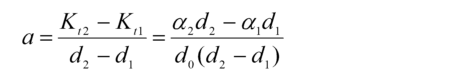
となる。
第3の関数IIIを
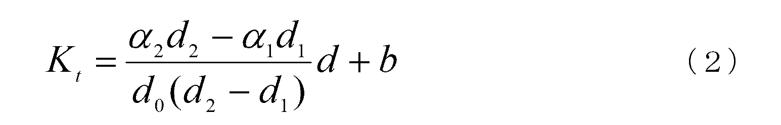
とすれば、第3の関数IIIは点(d1、Kt1=d1α1/d0)を通るから、この点の座標値を(2)式に代入した後、(2)式をbについて解けば、

が得られる。
こうして、第3の関数III、
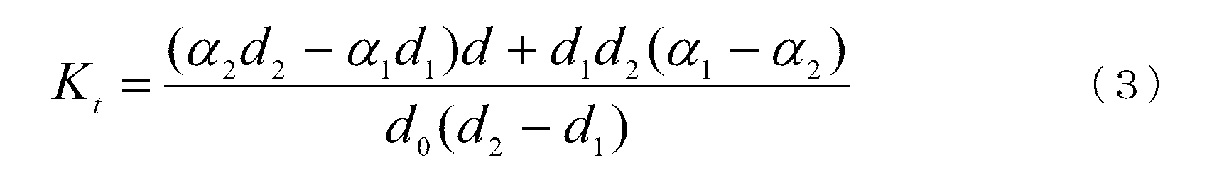
が得られる(生成される)。
こうして、第3の関数III、
図4Cは、第2および第4の関数のグラフを例示した図である。図4Cのグラフ中、縦軸は第2の回転速度係数KVを表し、横軸はクランパ2の搬送速度(冊/時)を表しており、また、直線IIは第2の関数であり、直線IVは第4の関数である。
なお、グラフの縦軸のスケールは、クランパ2の搬送速度が2000冊/時のときのポンプ6の回転速度を基準回転速度R0として、基準回転速度R0を1としたときの割合の値である。
なお、グラフの縦軸のスケールは、クランパ2の搬送速度が2000冊/時のときのポンプ6の回転速度を基準回転速度R0として、基準回転速度R0を1としたときの割合の値である。
図4Cを参照して、この実施例では、異なる2つのクランパ2の搬送速度(1000冊/時、4000冊/時)に対する第2の回転速度係数KVの補正倍率(90%、150%)が入力部10に入力され(図3参照)、関数生成部11において、それら2つのクランパ2の搬送速度と対応する補正倍率とに基づいて第4の関数IVが生成される。第4の関数IVも第3の関数IIIの場合と同様にして生成される。
なお、関数生成部11によって生成される第1~第5の関数はこの実施例に限定されず、一次関数以外の適当な任意の関数であってよい。
製本すべき本身Pの厚さの情報は、製本装置に付属する、あるいは製本装置とは別個に備えられた公知の本身厚さ測定ユニット(図示しない)による計測によって得られ、この計測値が制御部15に受信されるようになっている。
また、クランパ2の搬送速度は、製本装置の初期設定時に制御部15に入力されたものが使用される。
また、クランパ2の搬送速度は、製本装置の初期設定時に制御部15に入力されたものが使用される。
こうして、本発明の製本装置においては、本身の厚さとポンプの回転速度係数との関係を規定する第1の関数と、クランパの搬送速度とポンプの回転速度係数との関係を規定する第2の関数とを用いて、製本すべき本身の厚さおよびクランパの搬送速度設定値に応じた回転速度係数が算出され、当該回転速度係数および基準回転速度に基づいてポンプの回転速度設定値が算出され、回転速度設定値に従ってポンプの回転速度が自動的に初期設定されるので、ノズル噴射式糊塗布機構の初期設定作業が簡単にかつ短時間で行えるようになり、ユーザーの作業負担が大幅に低減される。
また、既定の第1および第2の関数を用いて自動的に設定されるポンプの回転速度ではユーザーの要望が満たされない場合は、ユーザーが、予め入力部10に第1の回転速度係数の補正倍率および/または第2の回転速度係数の補正倍率を入力しておけば、関数生成部11において、本身Pの厚さに応じた補正後の第1の回転速度係数を算出するための第3の関数、および/またはクランパ2の搬送速度に応じた補正後の第2の回転速度係数を算出するための第4の関数とが生成される。
そして、製本開始前に、ポンプ回転速度設定部9により、第3の関数を用いて、製本すべき本身Pの厚さに応じた補正後の第1の回転速度係数が算出され、および/または第4の関数を用いて、クランパ2の搬送速度設定値に応じた補正後の第2の回転速度係数が算出され、算出された補正後の第1および/または第2の回転速度係数を用いてポンプ6の回転速度設定値が算出され、この回転速度設定値に従ってポンプの回転速度が自動的に初期設定される。
加えて、噴射ノズル高さ設定部12によって、第5の関数を用いて、製本すべき本身Pの厚さに応じた糊噴射ノズル3の高さの設定値が算出され、この高さの設定値に従って、糊噴射ノズル3の高さが初期設定される。
こうして、本発明によれば、ノズル噴射式糊塗布機構Cの初期設定作業が簡単にかつ短時間で行えるようになり、ユーザーの作業負担が大幅に低減される。
こうして、本発明によれば、ノズル噴射式糊塗布機構Cの初期設定作業が簡単にかつ短時間で行えるようになり、ユーザーの作業負担が大幅に低減される。
また、製本開始前に、ノズル噴射式糊塗布機構Cの初期設定と同時に、クランパ2、ミリングユニットB、横糊ユニットD、表紙付けユニットEおよび表紙供給ユニットFについての初期設定がなされる。
そして、製本が開始されてクランパ2が本身供給位置Aに到達、停止するたびに、クランパ2が開位置をとり、本身供給ユニット(図示しない)によって、本身Pが、背が下向を向く配置でクランパ2に供給され、次いで、クランパ2が閉位置をとることによって、本身Pがクランパ2に挟持される。
その後、クランパ2は本身挿入位置Aを離れてミリングユニットBに向けて移動し、クランパ2に挟持された本身PがミリングユニットB上を通過する間に、本身Pの背面が切削される。次いで、クランパ2に挟持された本身Pは、ノズル噴射式糊塗布機構Cに送られる。
クランパ2に挟持された本身Pが、ノズル噴射式糊塗布機構Cの一対のガイド板8a、8bによって案内されつつ糊噴射ノズル3上を通過する間に、糊噴射ノズル3から本身Pの背にPUR糊が所定の厚さで塗布される
ノズル噴射式糊塗布機構Cによる糊付けが終了すると、クランパ2に挟持された本身Pは、横糊ユニットDを経て表紙付けユニットEに送られる。
ノズル噴射式糊塗布機構Cによる糊付けが終了すると、クランパ2に挟持された本身Pは、横糊ユニットDを経て表紙付けユニットEに送られる。
表紙付けユニットEにおいて、本身Pの背に表紙が貼着されて製本物P’が完成する。
その後、製本物P’はクランパ2によって挟持された状態で、弧状経路部分1c、上側直線状経路部分1aおよび弧状経路部分1dを通って本身挿入位置Aに到達、停止する。ここで、クランパ2は開位置をとり、製本物P’が製本物排出ユニットG上に落下し、製本装置の外部に搬送される。
その後、製本物P’はクランパ2によって挟持された状態で、弧状経路部分1c、上側直線状経路部分1aおよび弧状経路部分1dを通って本身挿入位置Aに到達、停止する。ここで、クランパ2は開位置をとり、製本物P’が製本物排出ユニットG上に落下し、製本装置の外部に搬送される。
以上、本発明の構成を好ましい実施例に基づいて説明したが、本発明の構成は上記実施例に限定されるものではなく、本願に添付の特許請求の範囲に記載した構成の範囲内で任意の変形例を案出することができる。
例えば、上記実施例では、初期設定時に、製本すべき本身Pの厚さおよびクランパ2の搬送速度設定値に応じてポンプ6の回転速度が調節されるとともに、製本すべき本身Pの厚さに応じて糊噴射ノズル3の高さが調節されるようになっているが、その代わりに、初期設定時に、本身Pの厚さのみに応じてポンプ6の回転速度のみが調節されるようになっていてもよい。
例えば、上記実施例では、初期設定時に、製本すべき本身Pの厚さおよびクランパ2の搬送速度設定値に応じてポンプ6の回転速度が調節されるとともに、製本すべき本身Pの厚さに応じて糊噴射ノズル3の高さが調節されるようになっているが、その代わりに、初期設定時に、本身Pの厚さのみに応じてポンプ6の回転速度のみが調節されるようになっていてもよい。
この場合には、入力部10はポンプ6の第1の回転速度係数の補正倍率の入力のみを受け、関数生成部11は第3の関数のみを生成し、ポンプ回転速度設定部9は、製本開始前、入力部10に第1の回転速度係数の補正倍率が入力されたときは、製本すべき本身Pの厚さに基づいて第3の関数から補正後の第1の回転速度係数を算出し、基準回転速度および補正後の第1の回転速度係数に基づいてポンプ6の回転速度設定値を算出し、算出した回転速度設定値に従ってポンプ6の回転速度を初期設定する。
あるいは、初期設定時に、クランパ2の搬送速度のみに応じてポンプ6の回転速度のみが調節されるようになっていてもよい。
この場合には、入力部10はポンプ6の第2の回転速度係数の補正倍率の入力のみを受け、関数生成部11は第4の関数のみを生成し、ポンプ回転速度設定部12は、製本開始前、入力部10に第2の回転速度係数の補正倍率が入力されたときは、クランパ2の搬送速度設定値に基づいて第4の関数から補正後の第2の回転速度係数を算出し、基準回転速度および補正後の第2の回転速度係数に基づいてポンプ6の回転速度設定値を算出し、算出した回転速度設定値を用いてポンプ6の回転速度を初期設定する。
この場合には、入力部10はポンプ6の第2の回転速度係数の補正倍率の入力のみを受け、関数生成部11は第4の関数のみを生成し、ポンプ回転速度設定部12は、製本開始前、入力部10に第2の回転速度係数の補正倍率が入力されたときは、クランパ2の搬送速度設定値に基づいて第4の関数から補正後の第2の回転速度係数を算出し、基準回転速度および補正後の第2の回転速度係数に基づいてポンプ6の回転速度設定値を算出し、算出した回転速度設定値を用いてポンプ6の回転速度を初期設定する。
また、例えば、上記実施例では、初期設定時に製本すべき本身Pの厚さに応じて糊噴射ノズル3の高さが調節される構成となっているが、この構成は必要に応じて備えられればよい。
また、上記実施例において、ポンプ6の回転速度が、製本すべき本身Pの厚さおよびクランパ2の搬送速度設定に加えて、糊噴射ノズル3の高さの設定値に応じて初期設定されるような構成とすることもできる。
この構成では、ポンプ回転速度設定部9が、第1の関数を用いて製本すべき本身Pの厚さに応じた第1の回転速度係数を算出し、およびクランパ2の搬送速度設定値に応じた第2の回転速度係数を算出するだけでなく、糊噴射ノズル3の高さと、ポンプ6の上記の基準回転速度を基準回転速度を基準とした回転速度の増減率を表す第3の回転速度係数との関係を規定する第6の関数を用いて、糊噴射ノズル3の高さの設定値に応じた第3の回転速度係数も算出し、算出した第1~第3の回転速度係数とポンプ6の基準回転速度とに基づきポンプ6の回転速度設定値を算出し、回転速度設定値に従ってポンプ6の回転速度を初期設定する。
この構成では、ポンプ回転速度設定部9が、第1の関数を用いて製本すべき本身Pの厚さに応じた第1の回転速度係数を算出し、およびクランパ2の搬送速度設定値に応じた第2の回転速度係数を算出するだけでなく、糊噴射ノズル3の高さと、ポンプ6の上記の基準回転速度を基準回転速度を基準とした回転速度の増減率を表す第3の回転速度係数との関係を規定する第6の関数を用いて、糊噴射ノズル3の高さの設定値に応じた第3の回転速度係数も算出し、算出した第1~第3の回転速度係数とポンプ6の基準回転速度とに基づきポンプ6の回転速度設定値を算出し、回転速度設定値に従ってポンプ6の回転速度を初期設定する。
また、この構成では、入力部10が、2つの異なる本身Pの厚さに対する第1の回転速度係数の補正倍率、および2つの異なるクランパ2の搬送速度に対する第2の回転速度係数の補正倍率、および2つの異なる糊噴射ノズル3の高さに対する第3の回転速度係数の補正倍率の入力を受け得る。
また、関数生成部11は、第3および第4の関数だけでなく、第3の回転速度係数の補正倍率に基づき糊噴射ノズル3の高さに応じた補正後の第3の回転速度係数を算出するための第7の関数も生成する。
また、関数生成部11は、第3および第4の関数だけでなく、第3の回転速度係数の補正倍率に基づき糊噴射ノズル3の高さに応じた補正後の第3の回転速度係数を算出するための第7の関数も生成する。
図6は、第6および第7の関数のグラフを例示した図である。図6のグラフ中、縦軸は第3の回転速度係数Khを表し、横軸は糊噴射ノズル3の高さ(mm)を表しており、直線VIは第6の関数であり、直線VIIは第7の関数である。
なお、グラフの縦軸のスケールは、糊噴射ノズル3の高さが-0.5mmのときのポンプ6の回転速度を基準回転速度R0として、基準回転速度R0を1としたときの割合の値である。
なお、グラフの縦軸のスケールは、糊噴射ノズル3の高さが-0.5mmのときのポンプ6の回転速度を基準回転速度R0として、基準回転速度R0を1としたときの割合の値である。
さらに、この構成では、ポンプ回転速度設定部9は、製本開始前、入力部10に第1~第3の回転速度係数の補正倍率が入力されたときは、製本すべき本身Pの厚さに基づいて第3の関数から補正後の第1の回転速度係数を算出し、およびクランパ2の搬送速度設定値に基づいて第4の関数から補正後の第2の回転速度係数を算出し、および糊噴射ノズル3の高さの設定値に基づいて第7の関数から補正後の第3の回転速度係数を算出し、算出した補正後の第1~第3の回転速度係数と基準回転速度とに基づいてポンプ6の回転速度設定値を算出し、算出した回転速度設定値に従ってポンプ6の回転速度を初期設定する。
1 経路
1a 上側直線状経路部分
1b 下側直線状経路部分
1c、1d 弧状経路部分
2 クランパ
3 糊噴射ノズル
4 PUR糊供給源
5 糊供給管
6 ポンプ
7 ノズル高さ調節機構
8a、8b ガイド板
9 ポンプ回転速度設定部
10 入力部
11 関数生成部
12 噴射ノズル高さ設定部
13 ディスプレイ
14 メモリ
15 制御部
16 第1の入力欄
16a 上段
16b 下段
17 第2の入力欄
17a 上段
17b 下段
18 第3の入力欄
18a 上段
18b 下段
19 リターンキー
20 切替タブ
A 本身供給位置
B ミリングユニット
C ノズル噴射式糊塗布機構
D 横糊ユニット
E 表紙付けユニット
F 表紙供給ユニット
G 製本物排出ユニット
g 表紙
k PUR糊
P 本身
P’ 製本物
Claims (4)
- 本身の搬送路の下側に配置されたノズル噴射式糊塗布機構と、前記本身を起立状態で挟持して前記搬送路に沿って搬送するクランパとを備え、
前記ノズル噴射式糊塗布機構は、
前記搬送路に向けて開口した糊噴射ノズルと、
糊供給源と、
前記糊供給源から前記糊噴射ノズルに糊を供給するための糊供給管と、
前記糊供給管に設けられたポンプと、を有し、
前記本身が前記搬送路に沿って搬送される間に、前記糊噴射ノズルから噴射された糊が前記本身の背に塗布される製本装置において、
前記本身の厚さと、前記ポンプの所定の基準回転速度を基準とした前記ポンプの回転速度の増減率を表す回転速度係数との関係を規定する第1の関数、および前記クランパの搬送速度と前記回転速度係数との関係を規定する第2の関数を用いて、製本すべき前記本身の厚さおよび前記クランパの搬送速度設定値に応じた前記回転速度係数を算出し、前記算出した回転速度係数および前記基準回転速度に基づいて前記ポンプの回転速度設定値を算出し、前記回転速度設定値に従って前記ポンプの回転速度を初期設定するポンプ回転速度設定部を備えたものであることを特徴とする製本装置。 - 2以上の異なる前記本身の厚さに対する前記回転速度係数の補正倍率の入力を受け得る入力部と、
前記入力部に入力された前記回転速度係数の補正倍率に基づき、前記第1の関数に代わる、前記本身の厚さに応じた補正後の前記回転速度係数を算出するための第3の関数を生成する関数生成部と、を備え、
前記ポンプ回転速度設定部が、製本開始前、前記入力部に前記回転速度係数の補正倍率が入力されたときは、前記第3の関数を用いて製本すべき前記本身の厚さに応じた前記補正後の回転速度係数を算出し、当該補正後の回転速度係数と、前記第2の関数を用いて算出した前記クランパの搬送速度設定値に応じた前記回転速度係数と、前記基準回転速度とに基づいて前記ポンプの回転速度設定値を算出するものであることを特徴とする請求項1に記載の製本装置。 - 2以上の異なる前記クランパの搬送速度に対する前記回転速度係数の補正倍率の入力を受け得る入力部と、
前記入力部に入力された前記回転速度係数の補正倍率に基づき、前記第2の関数に代わる、前記クランパの搬送速度に応じた補正後の前記回転速度係数を算出するための第4の関数を生成する関数生成部と、を備え、
前記ポンプ回転速度設定部が、製本開始前、前記入力部に前記回転速度係数の補正倍率が入力されたときは、前記第4の関数を用いて前記クランパの搬送速度設定値に応じた前記補正後の回転速度係数を算出し、当該補正後の回転速度係数と、前記第1の関数を用いて算出した製本すべき前記本身の厚さに応じた前記回転速度係数と、前記基準回転速度とに基づいて前記ポンプの回転速度設定値を算出するものであることを特徴とする請求項1に記載の製本装置。 - 2以上の異なる前記本身の厚さに対する前記回転速度係数の第1の補正倍率、および2以上の異なる前記クランパの搬送速度に対する前記回転速度係数の第2の補正倍率の入力を受け得る入力部と、
前記入力部に入力された前記第1の補正倍率に基づき、前記第1の関数に代わる、前記本身の厚さに応じた第1の補正後の前記回転速度係数を算出するための第3の関数を生成するとともに、前記入力部に入力された前記第2の補正倍率に基づき、前記第2の関数に代わる、前記クランパの搬送速度に応じた第2の補正後の前記回転速度係数を算出するための第4の関数を生成する関数生成部と、を備え、
前記ポンプ回転速度設定部が、製本開始前、前記入力部に前記第1および第2の補正倍率が入力されたときは、前記第3の関数を用いて製本すべき前記本身の厚さに応じた前記第1の補正後の回転速度係数を算出するとともに、前記第4の関数を用いて前記クランパの搬送速度設定値に応じた前記第2の補正後の回転速度係数を算出し、当該第1および第2の補正後の回転速度係数と、前記基準回転速度とに基づいて前記ポンプの回転速度設定値を算出するものであることを特徴とする請求項1に記載の製本装置。
Priority Applications (5)
| Application Number | Priority Date | Filing Date | Title |
|---|---|---|---|
| CN201780042972.9A CN109476172B (zh) | 2017-04-18 | 2017-04-18 | 装订装置 |
| JP2018558439A JP6862005B2 (ja) | 2017-04-18 | 2017-04-18 | 製本装置 |
| PCT/JP2017/015603 WO2018193523A1 (ja) | 2017-04-18 | 2017-04-18 | 製本装置 |
| US16/473,873 US10766290B2 (en) | 2017-04-18 | 2017-04-18 | Bookbinding machine |
| EP17906214.6A EP3613599B1 (en) | 2017-04-18 | 2017-04-18 | Bookbinding apparatus |
Applications Claiming Priority (1)
| Application Number | Priority Date | Filing Date | Title |
|---|---|---|---|
| PCT/JP2017/015603 WO2018193523A1 (ja) | 2017-04-18 | 2017-04-18 | 製本装置 |
Publications (1)
| Publication Number | Publication Date |
|---|---|
| WO2018193523A1 true WO2018193523A1 (ja) | 2018-10-25 |
Family
ID=63856508
Family Applications (1)
| Application Number | Title | Priority Date | Filing Date |
|---|---|---|---|
| PCT/JP2017/015603 WO2018193523A1 (ja) | 2017-04-18 | 2017-04-18 | 製本装置 |
Country Status (5)
| Country | Link |
|---|---|
| US (1) | US10766290B2 (ja) |
| EP (1) | EP3613599B1 (ja) |
| JP (1) | JP6862005B2 (ja) |
| CN (1) | CN109476172B (ja) |
| WO (1) | WO2018193523A1 (ja) |
Cited By (1)
| Publication number | Priority date | Publication date | Assignee | Title |
|---|---|---|---|---|
| JP2019126997A (ja) * | 2018-01-26 | 2019-08-01 | 大日本印刷株式会社 | 糊綴じ装置 |
Families Citing this family (1)
| Publication number | Priority date | Publication date | Assignee | Title |
|---|---|---|---|---|
| CN111231537A (zh) * | 2020-01-18 | 2020-06-05 | 杭州惠宝机电股份有限公司 | 一种书厚数控胶装运行的方法 |
Citations (6)
| Publication number | Priority date | Publication date | Assignee | Title |
|---|---|---|---|---|
| JPS60114372A (ja) * | 1983-11-25 | 1985-06-20 | Toppan Printing Co Ltd | 糊付装置 |
| US4975011A (en) * | 1989-09-27 | 1990-12-04 | Holmberg Albert E | Solvent activated bindable sheet and method and apparatus for producing bound booklets |
| JPH05201170A (ja) * | 1991-09-09 | 1993-08-10 | John C Tooker | 本構造体 |
| JP2005047199A (ja) * | 2003-07-31 | 2005-02-24 | Duplo Seiko Corp | 接着剤塗布装置、製本装置および接着剤塗布方法 |
| JP2009113407A (ja) | 2007-11-08 | 2009-05-28 | Pbm Kk | 製本機 |
| JP2014015043A (ja) * | 2012-07-10 | 2014-01-30 | Heiderberger Druckmaschinen Ag | 接着剤を塗布する装置及びそのような装置を運転する方法 |
Family Cites Families (16)
| Publication number | Priority date | Publication date | Assignee | Title |
|---|---|---|---|---|
| US4707215A (en) * | 1985-11-04 | 1987-11-17 | Xerox Corporation | Sheet binding cartridge |
| US4925354A (en) * | 1989-10-10 | 1990-05-15 | Am International Incorporated | Apparatus and method for applying adhesive to books |
| DE4013905C2 (de) * | 1990-04-26 | 1995-04-27 | Wohlenberg Vertriebs Und Servi | Leimwerk mit zugeordnetem Vorschmelzer für einen Klebebinder |
| DE4121792A1 (de) * | 1991-07-02 | 1993-01-07 | Kolbus Gmbh & Co Kg | Duesenauftragssystem |
| US5418009A (en) * | 1992-07-08 | 1995-05-23 | Nordson Corporation | Apparatus and methods for intermittently applying discrete adhesive coatings |
| JPH09183277A (ja) * | 1995-12-31 | 1997-07-15 | Tokyo Shuppan Kikai Kk | 自動丁合貼込機における糊塗布装置 |
| JP2835593B2 (ja) * | 1996-02-27 | 1998-12-14 | メルト技研株式会社 | ホットメルトガンの定量吐出装置 |
| DE19756958A1 (de) * | 1997-12-20 | 1999-07-15 | Womako Masch Konstr | Vorrichtung zum Beleimen von Blockrücken |
| EP1172230A3 (de) * | 2000-07-10 | 2003-12-03 | Sogno AG | Kleberauftragsstation für Druckerzeugnisse |
| DE20216794U1 (de) * | 2002-10-30 | 2004-03-11 | Nordson Corporation, Westlake | Vorrichtung zum Auftragen von Fluid |
| DE202006005590U1 (de) * | 2006-04-04 | 2007-08-16 | Nordson Corporation, Westlake | Vorrichtung zum Binden von Stapeln aus Flachteilen |
| WO2010067587A1 (ja) * | 2008-12-08 | 2010-06-17 | 株式会社デュプロ | 製本システム、製本用の糊付け装置および糊シート |
| EP2319707A1 (de) * | 2009-11-04 | 2011-05-11 | Müller Martini Holding AG | Vorrichtung zum Auftragen von Klebstoff auf den Rücken eines in einer Transportklammer einer Klebebindevorrichtung transportierten Buchblocks mittels Auftragsdüse |
| IT1403175B1 (it) * | 2010-10-20 | 2013-10-04 | Tumaini | Testa per l'applicazione di adesivo in macchine di rilegatura e macchina comprendente la testa |
| DE102010043156A1 (de) * | 2010-10-29 | 2012-05-03 | Henkel Ag & Co. Kgaa | Vorrichtung zum Binden von Stapeln aus Flachteilen |
| JP2015168142A (ja) * | 2014-03-06 | 2015-09-28 | 株式会社東芝 | シート綴じ装置、シート搬送装置 |
-
2017
- 2017-04-18 CN CN201780042972.9A patent/CN109476172B/zh active Active
- 2017-04-18 EP EP17906214.6A patent/EP3613599B1/en active Active
- 2017-04-18 US US16/473,873 patent/US10766290B2/en active Active
- 2017-04-18 WO PCT/JP2017/015603 patent/WO2018193523A1/ja unknown
- 2017-04-18 JP JP2018558439A patent/JP6862005B2/ja active Active
Patent Citations (6)
| Publication number | Priority date | Publication date | Assignee | Title |
|---|---|---|---|---|
| JPS60114372A (ja) * | 1983-11-25 | 1985-06-20 | Toppan Printing Co Ltd | 糊付装置 |
| US4975011A (en) * | 1989-09-27 | 1990-12-04 | Holmberg Albert E | Solvent activated bindable sheet and method and apparatus for producing bound booklets |
| JPH05201170A (ja) * | 1991-09-09 | 1993-08-10 | John C Tooker | 本構造体 |
| JP2005047199A (ja) * | 2003-07-31 | 2005-02-24 | Duplo Seiko Corp | 接着剤塗布装置、製本装置および接着剤塗布方法 |
| JP2009113407A (ja) | 2007-11-08 | 2009-05-28 | Pbm Kk | 製本機 |
| JP2014015043A (ja) * | 2012-07-10 | 2014-01-30 | Heiderberger Druckmaschinen Ag | 接着剤を塗布する装置及びそのような装置を運転する方法 |
Non-Patent Citations (1)
| Title |
|---|
| See also references of EP3613599A4 |
Cited By (1)
| Publication number | Priority date | Publication date | Assignee | Title |
|---|---|---|---|---|
| JP2019126997A (ja) * | 2018-01-26 | 2019-08-01 | 大日本印刷株式会社 | 糊綴じ装置 |
Also Published As
| Publication number | Publication date |
|---|---|
| US10766290B2 (en) | 2020-09-08 |
| JPWO2018193523A1 (ja) | 2020-02-27 |
| JP6862005B2 (ja) | 2021-04-21 |
| CN109476172B (zh) | 2021-03-23 |
| CN109476172A (zh) | 2019-03-15 |
| EP3613599A1 (en) | 2020-02-26 |
| US20200147991A1 (en) | 2020-05-14 |
| EP3613599A4 (en) | 2020-11-18 |
| EP3613599B1 (en) | 2022-02-23 |
Similar Documents
| Publication | Publication Date | Title |
|---|---|---|
| JP6857366B2 (ja) | 製本装置 | |
| WO2018193523A1 (ja) | 製本装置 | |
| CN110750883B (zh) | 一种溢流砖槽底曲线设计优化方法 | |
| JP4510472B2 (ja) | 包装材に接着剤を付与する方法と装置 | |
| US10195640B2 (en) | Method and apparatus for coating a moving substrate | |
| CN105242430B (zh) | 曲面对平面全贴合装置及方法 | |
| JP2014015043A (ja) | 接着剤を塗布する装置及びそのような装置を運転する方法 | |
| CN105068323A (zh) | 一种配向膜印刷补正方法及系统 | |
| US20050054502A1 (en) | Automated manufacturing line for boxgoods | |
| EP3585595A1 (de) | Verfahren und vorrichtung zum fügen mehrerer werkstoffplatten | |
| JP6355893B2 (ja) | フラックス塗布装置およびフラックス塗布方法 | |
| CN103373119B (zh) | 用于运行书籍成型和冲压机的方法 | |
| JP3813954B2 (ja) | 塗膜形成装置 | |
| CN108033055A (zh) | 贴合设备及贴合工艺 | |
| TW473878B (en) | Bonding paste applicator and method of using it | |
| CN212422442U (zh) | 一种蜂窝板生产线 | |
| CN105899345A (zh) | 用于胶合车辆内饰件的方法和生产系统 | |
| CN111532005A (zh) | 一种蜂窝板的生产方法 | |
| CN110303791A (zh) | 用来将可流动材料涂覆到基底上的设备 | |
| CN205380024U (zh) | 涂胶装置 | |
| CN102101086A (zh) | 用于分配膏的设备及其操作方法 | |
| JP2019166735A (ja) | 差圧成形装置、及び、差圧成形方法 | |
| CN208683261U (zh) | 多列袋包装设备的变间距调整结构 | |
| CN212636847U (zh) | 多维板生产线 | |
| JP2016016622A (ja) | ラッピング基材の製造方法及びその製造装置 |
Legal Events
| Date | Code | Title | Description |
|---|---|---|---|
| ENP | Entry into the national phase |
Ref document number: 2018558439 Country of ref document: JP Kind code of ref document: A |
|
| 121 | Ep: the epo has been informed by wipo that ep was designated in this application |
Ref document number: 17906214 Country of ref document: EP Kind code of ref document: A1 |
|
| NENP | Non-entry into the national phase |
Ref country code: DE |
|
| ENP | Entry into the national phase |
Ref document number: 2017906214 Country of ref document: EP Effective date: 20191118 |