WO2018190422A1 - スクイズボトル - Google Patents
スクイズボトル Download PDFInfo
- Publication number
- WO2018190422A1 WO2018190422A1 PCT/JP2018/015546 JP2018015546W WO2018190422A1 WO 2018190422 A1 WO2018190422 A1 WO 2018190422A1 JP 2018015546 W JP2018015546 W JP 2018015546W WO 2018190422 A1 WO2018190422 A1 WO 2018190422A1
- Authority
- WO
- WIPO (PCT)
- Prior art keywords
- squeeze bottle
- polyethylene
- liquid composition
- container body
- container
- Prior art date
Links
Images


Classifications
-
- B—PERFORMING OPERATIONS; TRANSPORTING
- B65—CONVEYING; PACKING; STORING; HANDLING THIN OR FILAMENTARY MATERIAL
- B65D—CONTAINERS FOR STORAGE OR TRANSPORT OF ARTICLES OR MATERIALS, e.g. BAGS, BARRELS, BOTTLES, BOXES, CANS, CARTONS, CRATES, DRUMS, JARS, TANKS, HOPPERS, FORWARDING CONTAINERS; ACCESSORIES, CLOSURES, OR FITTINGS THEREFOR; PACKAGING ELEMENTS; PACKAGES
- B65D35/00—Pliable tubular containers adapted to be permanently or temporarily deformed to expel contents, e.g. collapsible tubes for toothpaste or other plastic or semi-liquid material; Holders therefor
- B65D35/02—Body construction
- B65D35/04—Body construction made in one piece
- B65D35/08—Body construction made in one piece from plastics material
-
- A—HUMAN NECESSITIES
- A61—MEDICAL OR VETERINARY SCIENCE; HYGIENE
- A61J—CONTAINERS SPECIALLY ADAPTED FOR MEDICAL OR PHARMACEUTICAL PURPOSES; DEVICES OR METHODS SPECIALLY ADAPTED FOR BRINGING PHARMACEUTICAL PRODUCTS INTO PARTICULAR PHYSICAL OR ADMINISTERING FORMS; DEVICES FOR ADMINISTERING FOOD OR MEDICINES ORALLY; BABY COMFORTERS; DEVICES FOR RECEIVING SPITTLE
- A61J1/00—Containers specially adapted for medical or pharmaceutical purposes
- A61J1/14—Details; Accessories therefor
- A61J1/1412—Containers with closing means, e.g. caps
-
- A—HUMAN NECESSITIES
- A61—MEDICAL OR VETERINARY SCIENCE; HYGIENE
- A61J—CONTAINERS SPECIALLY ADAPTED FOR MEDICAL OR PHARMACEUTICAL PURPOSES; DEVICES OR METHODS SPECIALLY ADAPTED FOR BRINGING PHARMACEUTICAL PRODUCTS INTO PARTICULAR PHYSICAL OR ADMINISTERING FORMS; DEVICES FOR ADMINISTERING FOOD OR MEDICINES ORALLY; BABY COMFORTERS; DEVICES FOR RECEIVING SPITTLE
- A61J1/00—Containers specially adapted for medical or pharmaceutical purposes
- A61J1/14—Details; Accessories therefor
- A61J1/1475—Inlet or outlet ports
-
- B—PERFORMING OPERATIONS; TRANSPORTING
- B65—CONVEYING; PACKING; STORING; HANDLING THIN OR FILAMENTARY MATERIAL
- B65D—CONTAINERS FOR STORAGE OR TRANSPORT OF ARTICLES OR MATERIALS, e.g. BAGS, BARRELS, BOTTLES, BOXES, CANS, CARTONS, CRATES, DRUMS, JARS, TANKS, HOPPERS, FORWARDING CONTAINERS; ACCESSORIES, CLOSURES, OR FITTINGS THEREFOR; PACKAGING ELEMENTS; PACKAGES
- B65D1/00—Containers having bodies formed in one piece, e.g. by casting metallic material, by moulding plastics, by blowing vitreous material, by throwing ceramic material, by moulding pulped fibrous material, by deep-drawing operations performed on sheet material
- B65D1/02—Bottles or similar containers with necks or like restricted apertures, designed for pouring contents
- B65D1/0207—Bottles or similar containers with necks or like restricted apertures, designed for pouring contents characterised by material, e.g. composition, physical features
-
- B—PERFORMING OPERATIONS; TRANSPORTING
- B65—CONVEYING; PACKING; STORING; HANDLING THIN OR FILAMENTARY MATERIAL
- B65D—CONTAINERS FOR STORAGE OR TRANSPORT OF ARTICLES OR MATERIALS, e.g. BAGS, BARRELS, BOTTLES, BOXES, CANS, CARTONS, CRATES, DRUMS, JARS, TANKS, HOPPERS, FORWARDING CONTAINERS; ACCESSORIES, CLOSURES, OR FITTINGS THEREFOR; PACKAGING ELEMENTS; PACKAGES
- B65D47/00—Closures with filling and discharging, or with discharging, devices
- B65D47/04—Closures with discharging devices other than pumps
- B65D47/20—Closures with discharging devices other than pumps comprising hand-operated members for controlling discharge
-
- A—HUMAN NECESSITIES
- A61—MEDICAL OR VETERINARY SCIENCE; HYGIENE
- A61J—CONTAINERS SPECIALLY ADAPTED FOR MEDICAL OR PHARMACEUTICAL PURPOSES; DEVICES OR METHODS SPECIALLY ADAPTED FOR BRINGING PHARMACEUTICAL PRODUCTS INTO PARTICULAR PHYSICAL OR ADMINISTERING FORMS; DEVICES FOR ADMINISTERING FOOD OR MEDICINES ORALLY; BABY COMFORTERS; DEVICES FOR RECEIVING SPITTLE
- A61J1/00—Containers specially adapted for medical or pharmaceutical purposes
- A61J1/05—Containers specially adapted for medical or pharmaceutical purposes for collecting, storing or administering blood, plasma or medical fluids ; Infusion or perfusion containers
- A61J1/06—Ampoules or carpules
- A61J1/067—Flexible ampoules, the contents of which are expelled by squeezing
-
- A—HUMAN NECESSITIES
- A61—MEDICAL OR VETERINARY SCIENCE; HYGIENE
- A61J—CONTAINERS SPECIALLY ADAPTED FOR MEDICAL OR PHARMACEUTICAL PURPOSES; DEVICES OR METHODS SPECIALLY ADAPTED FOR BRINGING PHARMACEUTICAL PRODUCTS INTO PARTICULAR PHYSICAL OR ADMINISTERING FORMS; DEVICES FOR ADMINISTERING FOOD OR MEDICINES ORALLY; BABY COMFORTERS; DEVICES FOR RECEIVING SPITTLE
- A61J1/00—Containers specially adapted for medical or pharmaceutical purposes
- A61J1/14—Details; Accessories therefor
- A61J1/1468—Containers characterised by specific material properties
-
- B—PERFORMING OPERATIONS; TRANSPORTING
- B65—CONVEYING; PACKING; STORING; HANDLING THIN OR FILAMENTARY MATERIAL
- B65D—CONTAINERS FOR STORAGE OR TRANSPORT OF ARTICLES OR MATERIALS, e.g. BAGS, BARRELS, BOTTLES, BOXES, CANS, CARTONS, CRATES, DRUMS, JARS, TANKS, HOPPERS, FORWARDING CONTAINERS; ACCESSORIES, CLOSURES, OR FITTINGS THEREFOR; PACKAGING ELEMENTS; PACKAGES
- B65D1/00—Containers having bodies formed in one piece, e.g. by casting metallic material, by moulding plastics, by blowing vitreous material, by throwing ceramic material, by moulding pulped fibrous material, by deep-drawing operations performed on sheet material
- B65D1/09—Ampoules
- B65D1/095—Ampoules made of flexible material
-
- Y—GENERAL TAGGING OF NEW TECHNOLOGICAL DEVELOPMENTS; GENERAL TAGGING OF CROSS-SECTIONAL TECHNOLOGIES SPANNING OVER SEVERAL SECTIONS OF THE IPC; TECHNICAL SUBJECTS COVERED BY FORMER USPC CROSS-REFERENCE ART COLLECTIONS [XRACs] AND DIGESTS
- Y02—TECHNOLOGIES OR APPLICATIONS FOR MITIGATION OR ADAPTATION AGAINST CLIMATE CHANGE
- Y02W—CLIMATE CHANGE MITIGATION TECHNOLOGIES RELATED TO WASTEWATER TREATMENT OR WASTE MANAGEMENT
- Y02W30/00—Technologies for solid waste management
- Y02W30/50—Reuse, recycling or recovery technologies
- Y02W30/80—Packaging reuse or recycling, e.g. of multilayer packaging
Definitions
- the present invention relates to a squeeze bottle.
- Patent Document 1 discloses a plastic ampoule integrally formed by a blow fill seal (BFS) method in which container forming, filling of an aqueous pharmaceutical preparation and sealing of the container are performed continuously. Is disclosed.
- BFS blow fill seal
- An object of the present invention is to provide a squeeze bottle which is an integrally formed squeeze bottle for containing a liquid composition and has excellent operability when dropped or poured out.
- the present inventors have found that a squeeze bottle formed integrally with a resin containing cyclic olefins and polyethylene is surprisingly excellent in operability when dropped or poured out.
- a container body including a storage part for storing the liquid composition, and a spout provided continuously to the storage part;
- the said container main body is a squeeze bottle containing resin containing cyclic olefins and polyethylene.
- the squeeze bottle according to [1] or [2], wherein the compressive strength on the side surface of the housing portion is 20 to 250 N / mm.
- the total content of the cyclic olefins in the resin layer containing cyclic olefins and polyethylene in contact with the liquid composition is 50 to 50 on the basis of the total amount of resins containing the cyclic olefins and polyethylenes.
- a method for producing a squeeze bottle comprising integrally molding a resin containing cyclic olefins and polyethylene.
- a squeeze bottle for housing a liquid composition which is an integrally formed squeeze bottle and has excellent operability when dropped or poured out.
- (A) is a front view which shows the structure of the squeeze bottle which concerns on one Embodiment of this invention
- (b) is a left view which shows the structure of the squeeze bottle which concerns on one Embodiment of this invention. It is a front view which shows the structure which connected multiple squeeze bottles which concern on one Embodiment of this invention. It is a perspective view which shows the method of measuring the maximum test force.
- (A) is a front view which shows the structure of the squeeze bottle produced in Test Example 4
- (b) is a left side view which shows the structure of the squeeze bottle produced in Test Example 4.
- FIG. 1 is the figure which showed typically the cross section (cross section along the direction perpendicular
- FIG. It is a front view which shows the squeeze bottle of the state connected with two or more produced by the test example 4.
- FIG.1 (a) is a front view which shows the structure of the squeeze bottle which concerns on one Embodiment of this invention
- FIG.1 (b) is a left view which shows the structure of the squeeze bottle which concerns on one Embodiment of this invention. It is.
- the squeeze bottle 1 includes a container body 2 including a container 3 for containing a liquid composition, and a spout 4 connected to the container 3; And a lid 6 joined to the container body 2 so as to seal the opening 5 of the spout 4.
- the squeeze bottle according to the present embodiment may further integrally include a thin portion that connects the opening 5 of the spout 4 and the lid 6. In the above configuration, the opening 5 of the spout 4 is opened by gripping the container 3 and the lid 6 and twisting and tearing them in opposite directions.
- FIG. 2 is a front view showing a configuration in which a plurality of squeeze bottles according to an embodiment of the present invention are connected. As shown in FIG. 2, it is also possible to shape
- One squeeze bottle can be separated from a plurality of connected squeeze bottles.
- the squeeze bottle according to the present embodiment is a discharge container that discharges the contained liquid composition.
- the liquid composition is discharged out of the squeeze bottle by dropping or pouring.
- the container body of the squeeze bottle according to this embodiment includes a resin containing cyclic olefins and polyethylene (also simply referred to as “cyclic olefins and polyethylene-containing resin”).
- cyclic olefins examples include a cyclic olefin polymer (also simply referred to as “COP”) and a cyclic olefin copolymer (also simply referred to as “COC”).
- COP cyclic olefin polymer
- COC cyclic olefin copolymer
- the cyclic olefins are preferably COC from the viewpoint of more prominently achieving the effects of the present invention.
- COP is not particularly limited as long as it contains a polymer obtained by copolymerizing one kind of cyclic olefin, a polymer obtained by copolymerization of two or more kinds of cyclic olefins, or a hydrogenated product thereof.
- the COP preferably contains a ring-opening polymer of a cyclic olefin or a hydrogenated product thereof.
- the COP preferably contains an amorphous polymer.
- COC is not particularly limited as long as it contains a polymer obtained by copolymerizing a cyclic olefin and an acyclic olefin, or a hydrogenated product thereof.
- Examples of the cyclic olefin include a monocyclic or polycyclic cycloalkane having a vinyl group, a monocyclic or polycyclic cycloalkene, and derivatives thereof.
- Preferred cyclic olefins are norbornene, tetracyclododecene, and derivatives thereof.
- Examples of the acyclic olefin include ⁇ -olefins such as ethylene, propylene, 1-butene, 1-pentene and 1-hexene.
- the COP those containing a polymer of a cyclic olefin having a norbornene skeleton or a hydrogenated product thereof from the viewpoint of more prominently achieving the effects of the present invention are preferable.
- the COC those containing a polymer obtained by copolymerizing norbornene and ethylene are preferable from the viewpoint of more prominently achieving the effects of the present invention.
- the polymer which copolymerized cyclic olefin and acyclic olefin may contain the other monomer as a structural component of the said polymer.
- the glass transition temperatures of the cyclic olefins are, for example, 60 to 200 ° C., 60 to 180 ° C., 60 to 160 ° C., 60 to 150 ° C., 60 to 140 ° C., 65 to 130 ° C., 65 to 120 ° C., 65 to 110 ° C. 65 to 100 ° C, or 65 to 90 ° C.
- the glass transition temperature can be measured by a method based on ISO11375.
- cyclic olefins commercially available products can be used without particular limitation.
- examples of commercially available COPs include ZEONEX (registered trademark) (manufactured by ZEON Corporation) and ZEONOR (registered trademark) (manufactured by ZEON Corporation).
- Examples of commercially available COCs include TOPAS (registered trademark) (manufactured by Polyplastics) and Apel (registered trademark) (manufactured by Mitsui Chemicals, Inc.).
- PE polyethylene
- HDPE high density polyethylene
- MDPE medium density polyethylene
- LDPE low density polyethylene
- LLDPE linear low density polyethylene
- the polyethylene is preferably LDPE or LLDPE, more preferably LLDPE, from the viewpoint of more prominently achieving the effects of the present invention.
- Polyethylenes may be homopolymers or copolymers.
- examples of the comonomer include ⁇ -olefins such as 1-butene, 1-pentene, 1-hexene, 1-octene and 1-decene.
- the density of the polyethylene is, for example, 0.900 to 0.980 kg / m 3 , 0.900 to 0.942 kg / m 3 , 0.902 to 0.940 kg / m 3 , 0.902 to 0.930 kg / m. 3 , 0.905 to 0.927 kg / m 3 , or 0.908 to 0.920 kg / m 3 .
- polyethylenes commercially available products can be used without particular limitation.
- examples of commercially available polyethylenes include Novatec (registered trademark) (manufactured by Nippon Polyethylene Co., Ltd.), Ultzex (registered trademark) (manufactured by Mitsui Chemicals), Evolue (registered trademark) (manufactured by Prime Polymer Co., Ltd.), UBE polyethylene (registered trademark) B128H (manufactured by Ube Maruzen Polyethylene Co., Ltd.), Umerit (registered trademark) (manufactured by Prime Polymer Co., Ltd.), Petrocene (registered trademark) (manufactured by Tosoh Corporation), Nipolon (registered trademark) (Tosoh Corporation) Product), LUMITAC (registered trademark) (manufactured by Tosoh Corporation), Suntec (registered trademark) (manufactured by Asahi Kasei Chemicals Corporation), and Purell PE (
- cyclic olefins and polyethylene-containing resins examples include polypropylene (PP), polycarbonate, (meth) acrylic acid polymer, polystyrene (PS), polyethylene naphthalate (PEN), polyethylene terephthalate (PET). ), And other polymers such as polyarylate may be included.
- the cyclic olefins and polyethylene-containing resins according to the present embodiment include stabilizers, modifiers, colorants, ultraviolet absorbers, metal oxides, oxygen absorbers, antibacterial agents, plasticizers, glass fibers, and the like. Additives may be included.
- the container main body of a squeeze bottle consists of two or more layers containing an inner layer and an outer layer, it is preferable to make these additives contain in an outer layer.
- the container body of the squeeze bottle according to this embodiment may have a single-layer structure including a cyclic olefin and a polyethylene-containing resin, or may have a multilayer structure including a layer including a cyclic olefin and a polyethylene-containing resin.
- the layer containing the cyclic olefins and the polyethylene-containing resin may be an inner layer in contact with the liquid composition.
- it may be an outer layer (or intermediate layer) that is not in contact with the composition, it is preferably an inner layer from the viewpoint of more prominently achieving the effects of the present invention.
- the layer containing the cyclic olefins and the polyethylene-containing resin is an inner layer in contact with the liquid composition
- the type of resin that forms the outer layer or intermediate layer
- polyethylene PE
- PP polypropylene
- PET polyethylene terephthalate
- PS polystyrene
- ABS acrylonitrile butadiene styrene
- polycarbonate polymethyl methacrylate
- ethylene vinyl acetate copolymer and
- One or more polymers selected from the group consisting of ethylene vinyl alcohol copolymers may be included as a constituent component.
- the resin forming the outer layer is preferably polyethylene (PE), polypropylene (PP), or ethylene vinyl alcohol copolymer, more preferably from the viewpoint of more prominently achieving the effects of the present invention.
- PE polyethylene
- PP polypropylene
- ethylene vinyl alcohol copolymer more preferably from the viewpoint of more prominently achieving the effects of the present invention.
- LDPE low density polyethylene
- LLDPE low density polyethylene
- PP polypropylene
- ethylene vinyl alcohol copolymer more preferably from the viewpoint of more prominently achieving the effects of the present invention.
- the container body of the squeeze bottle has a single layer structure including a cyclic olefin and a polyethylene-containing resin, or a multilayer structure including a layer including a cyclic olefin and a polyethylene-containing resin
- the layer containing an olefin and a polyethylene-containing resin is an inner layer in contact with the liquid composition
- a layer containing a cyclic olefin in contact with the liquid composition and a resin containing polyethylene (a single layer or an inner layer in contact with the liquid composition)
- the content of cyclic olefins in () is not particularly limited, and is appropriately set according to the type of cyclic olefins, the type and content of other compounding components, and the like.
- the total content of cyclic olefins is 10 to 99% by mass, 30 to 99% by mass, 50 to 99% by mass, 55 to 99% by mass, 60% based on the total amount of cyclic olefins and polyethylene-containing resins. It may be -99 mass%, 65-99 mass%, 70-99 mass%, 75-96 mass%, 80-96 mass%, 85-96 mass%, or 90-96 mass%.
- the container body of the squeeze bottle according to the present embodiment has a single layer structure including a cyclic olefin and a polyethylene-containing resin, or a multilayer structure including a layer including a cyclic olefin and a polyethylene-containing resin
- the layer containing the olefins and the polyethylene-containing resin is an inner layer in contact with the liquid composition
- the resin layer (single layer or inner layer in contact with the liquid composition) containing the cyclic olefins and polyethylene in contact with the liquid composition The content of polyethylene is not particularly limited, and is appropriately set according to the type of polyethylene, the type and content of other compounding components, and the like.
- the content of polyethylene in the resin layer (single layer or inner layer in contact with the liquid composition) containing the cyclic olefins and polyethylene in contact with the liquid composition is, for example, from the viewpoint of more prominently achieving the effects of the present invention.
- the total content of polyethylene is 1 to 50% by mass, 5 to 50% by mass, 10 to 50% by mass, 15 to 50% by mass, and 20 to 50%. It may be mass%, 25-45 mass%, 30-45 mass%, 35-45 mass%, or 40-45 mass%.
- the content of polyethylene in the container body of the squeeze bottle according to the present embodiment is not particularly limited, and is appropriately set according to the type of polyethylene, the type and content of other compounding components, and the like.
- the polyethylene content in the container body is, for example, from the viewpoint of more prominently achieving the effects of the present invention, for example, based on the mass of the container body, the total polyethylene content is 10 to 95% by mass, 30 to 95%. Mass%, 35-90 mass%, 40-85 mass%, 40-83 mass%, 40-80 mass%, 45-78 mass%, 45-75 mass%, 45-70 mass%, 50-65 mass% Or 50 to 60% by mass.
- the container body of the squeeze bottle has a single layer structure including a cyclic olefin and a polyethylene-containing resin, or a multilayer structure including a layer including a cyclic olefin and a polyethylene-containing resin
- the layer containing the olefins and the polyethylene-containing resin is an inner layer in contact with the liquid composition
- the resin layer single layer or inner layer in contact with the liquid composition
- the blending ratio of polyethylene to cyclic olefins is not particularly limited, and is appropriately set according to the types of cyclic olefins and polyethylene, the types and contents of other blending components, and the like.
- the blending ratio of polyethylene to cyclic olefins in the resin layer (single layer or inner layer in contact with the liquid composition) containing cyclic olefins and polyethylene in contact with the liquid composition is more prominent in the effect of the present invention.
- the total content of polyethylenes is 0.01 to 9.0 parts by mass, 0.01 to 2.5 parts by mass, 0.005 parts by mass with respect to 1 part by mass of the total content of cyclic olefins.
- the resin for molding the lid of the squeeze bottle according to the present embodiment is not particularly limited, but from the viewpoint that the container body and the lid can be integrally molded by the blow fill seal (BFS) method, the same resin as the container body It is preferable that
- the area of the spout of the opening of the squeeze bottle according to the present embodiment from the viewpoint of the effect of the present invention more remarkable, for example, 0.15 ⁇ 20.0mm 2, 0.2 ⁇ 20.0mm 2, 0.2 ⁇ 18.0mm 2, 0.2 ⁇ 16.0mm 2, 0.2 ⁇ 14.0mm 2, 0.2 ⁇ 12.6mm 2, 0.2 ⁇ 11.0mm 2, 0.2 ⁇ 9 It may be 0.7 mm 2 , 0.5 to 8.0 mm 2 , 0.79 to 7.1 mm 2 , 0.79 to 6.2 mm 2 , or 0.79 to 5.0 mm 2 .
- the area of the opening of the spout can be calculated by measuring the diameter of the opening or the major and minor diameters of the opening using a caliper, a micrometer, a universal projector, a stereomicroscope, or the like.
- the shape of the opening part of a spout can be designed suitably. From the viewpoint of exhibiting the effect of the present invention more remarkably, a circular shape or an elliptical shape is preferable.
- the compressive strength at the side surface of the housing portion of the squeeze bottle according to the present embodiment is, for example, 20 to 250 N / mm, 20 to 240 N / mm, 20 to 230 N / mm, from the viewpoint that the effects of the present invention are more remarkably exhibited.
- the “side surface of the storage portion” includes a portion that is normally gripped with a finger when the liquid composition is dropped or poured out.
- “side surface of the storage portion” Means "the peripheral surface of the accommodating part”.
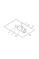
- FIG. 3 is a perspective view showing a method for measuring the maximum test force when the shape of the cross section of the container (the cross section along the direction perpendicular to the direction in which the liquid composition is dropped or poured) is circular or elliptical. It is.
- the dotted line drawn in the height direction of the container body on the side surface (circumferential surface) 3 a of the storage unit indicates a portion where the side surface (circumferential surface) 3 a of the storage unit is in contact with the plane 10. ing.
- a measurement probe on a side surface (peripheral surface) 3a of the housing portion that is usually held by a fingertip 12 for dropping or pouring the liquid composition (one location; hereinafter also referred to as “maximum test force measurement site”) 11 is brought into contact with each other, and the maximum value of force (hereinafter referred to as “maximum test force”) required to push a distance (h / 2) half the distance h between the maximum test force measurement site 12 and the plane 10 at a speed of 100 mm / min.
- the measurement probe 11 has a shape such that all of the end surfaces thereof are in contact with the maximum test force measurement site 12 on the side surface (circumferential surface) 3a of the housing portion and do not penetrate the side surface (circumferential surface) 3a of the housing portion. Select one as appropriate. Further, the bottom surface 3b of the housing portion is not a part for measuring the maximum test force. 3) According to the following formula 1, a value obtained by dividing the measured maximum test force by the thickness of the maximum test force measurement site (hereinafter also referred to as “maximum test force per unit thickness”) is calculated.
- the shape of the cross section (the cross section along the direction perpendicular to the direction in which the liquid composition is dropped or poured out) of the housing portion of the squeeze bottle according to the present embodiment can be designed as appropriate. From the viewpoint of achieving the effects of the present invention more remarkably, a circle, an ellipse, a rectangle, or a polygon is preferable, and an ellipse or a rectangle is more preferable.
- the dropping amount per drop dropped from the spout of the squeeze bottle according to the present embodiment can be designed to be 1 to 130 ⁇ L from the viewpoint of more prominently achieving the effects of the present invention. It is preferably ⁇ 99 ⁇ L, more preferably 1 to 79 ⁇ L, even more preferably 7 to 79 ⁇ L, and even more preferably 13 to 79 ⁇ L.
- the dropping amount per drop can be adjusted by setting the area of the opening of the spout and the compressive strength on the peripheral surface of the storage portion within the above-mentioned range.
- the capacity of the squeeze bottle according to the present embodiment is not particularly limited, and may be set as appropriate according to the application.
- the squeeze bottle may be a container that accommodates a liquid composition that is used a large number of times (for example, 25 times or more), and a liquid that is used a small number of times (for example, 2 times or more and less than 25 times).
- the container in which a composition is accommodated may be sufficient, and the container in which the liquid composition of the single use amount is accommodated may be sufficient.
- the squeeze bottle according to the present embodiment is preferably a container in which a small amount or a single use amount of the liquid composition is accommodated.
- the squeeze bottle according to the present embodiment is, for example, a container containing an eye drop, a contact lens mounting solution, an eye wash or a nasal drop
- the volume is 0.01 mL to 50 mL, 0.05 mL to 40 mL, It may be 1 mL or more and 25 mL or less.
- the squeeze bottle is a container that contains, for example, an eye drop, a contact lens mounting solution, an eye wash, a nasal drop, a hair growth agent, or a hair growth agent, and is used a small number of times (for example, 2 times to less than 25 times) Or in the case of a single container, the volume is 0.01 mL or more and 7 mL or less, 0.05 mL or more and 6 mL or less, 0.1 mL or more and 5 mL or less, 0.1 mL or more and 4 mL or less, 0.1 mL or more and 3 mL or less, 0.1 mL It may be 2.5 mL or less, 0.2 mL or more and 2 mL or less, 0.2 mL or more and 1.5 mL or less, or 0.2 mL or more and 1 mL or less.
- the container body of the squeeze bottle according to the present embodiment preferably has transparency from the viewpoint that the confirmation of the foreign matter, the confirmation of the remaining amount, etc. can be observed with the naked eye.
- the container body of the squeeze bottle may be colorless or colored as long as it has transparency.
- the container body of the squeeze bottle only needs to have transparency with sufficient internal visibility so that the inside can be observed with the naked eye. If the above-mentioned internal visibility is ensured in a part of the container body, the container body is not necessarily used. The entire surface of the main body does not need to have uniform transparency.
- the maximum value of light transmittance in the visible light region of a squeeze bottle having a wavelength of 400 to 700 nm is 50% or more, 55% or more, or 60% or more. 65% or more, 70% or more, 75% or more, 80% or more, 85% or more, 90% or more, or 95% or more.
- the maximum light transmittance can be obtained from each light transmittance obtained by measuring the light transmittance every 10 nm between wavelengths of 400 to 700 nm using a microplate reader or the like.
- the thickness of the container body of the squeeze bottle according to the present embodiment is, for example, 0.01 to 2.0 mm, 0.05 to 1.8 mm, 0.08 to 1. 5mm, 0.08-1.2mm, 0.08-1.0mm, 0.08-0.8mm, 0.1-0.6mm, 0.1-0.5mm, or 0.1-0.4mm It may be.
- the thickness of the layer containing the cyclic olefins and the polyethylene-containing resin is, for example, 0. 01 to 1.0 mm, 0.05 to 0.8 mm, 0.08 to 0.6 mm, 0.08 to 0.5 mm, 0.08 to 0.4 mm, 0.08 to 0.3 mm, or 0.1 It may be up to 0.2 mm.
- the liquid composition accommodated in the squeeze bottle according to the present embodiment only needs to have fluidity that can be filled in the accommodating portion of the container.
- the viscosity of the liquid composition accommodated in the squeeze bottle according to the present embodiment is not particularly limited as long as it is within a pharmaceutically, pharmacologically (pharmaceutical) or physiologically acceptable range.
- the viscosity of the liquid composition for example, the viscosity at 20 ° C.
- a rotational viscometer (RE550 viscometer, manufactured by Toki Sangyo Co., Ltd., rotor: 1 ° 34 ′ ⁇ R24) is 0.5 to 1000 mPa ⁇ s, 0.8 to 500 mPa ⁇ s, 1.0 to 250 mPa ⁇ s, 1.0 to 100 mPa ⁇ s, 1.0 to 80 mPa ⁇ s, 1.0 to 70 mPa ⁇ s, 1.0 to 60 mPa ⁇ s, 0 to 50 mPa ⁇ s, 1.0 to 40 mPa ⁇ s, 1.0 to 30 mPa ⁇ s, 1.0 to 25 mPa ⁇ s, 1.0 to 20 mPa ⁇ s, 1.0 to 15 mPa ⁇ s, 1.0 to 10 mPa ⁇ s, 1.0 to 8.0 mPa ⁇ s, 1.0 to 7.0 mPa ⁇ s
- the liquid composition contained in the squeeze bottle according to the present embodiment may be an aqueous composition or an oily composition, but is preferably an aqueous composition.
- specific examples of the liquid composition accommodated in the squeeze bottle according to the present embodiment include, for example, an external liquid composition such as an ophthalmic composition, an otolaryngological composition, and a skin composition; And ophthalmic compositions are preferred.
- the content of water is, for example, based on the total amount of the liquid composition from the viewpoint of more prominently achieving the effects of the present invention.
- the water content is 15 w / v% or more and less than 100 w / v%, 20 w / v% or more and less than 100 w / v%, 25 w / v% or more and less than 99.5 w / v%, 30 w / v% or more and 99.99.
- the squeeze bottle When the liquid composition accommodated in the squeeze bottle according to this embodiment is an ophthalmic composition, specific examples of the squeeze bottle include, for example, an eye drop container, an eye wash container, and a contact lens mounting liquid container
- the container may be a contact lens care liquid container (including a contact lens cleaning liquid container, a contact lens storage liquid container, a contact lens disinfectant container, a contact lens multipurpose solution container, etc.).
- the type of squeeze bottle is preferably an eye drop container, an eyewash container, a contact lens mounting liquid container, or a contact lens care liquid container.
- the squeeze bottle according to the present embodiment is excellent in operability when discharging (dropping or pouring) the stored liquid composition, the liquid composition is discharged as intended by the user. Can do.
- the “contact lens” includes hard contact lenses and soft contact lenses (including both ionic and non-ionic, including both silicone hydrogel contact lenses and non-silicone hydrogel contact lenses).
- the squeeze bottle according to the present embodiment can be manufactured by, for example, a blow fill seal (BFS) method described in Patent Document 1.
- BFS blow fill seal
- a squeeze bottle including a container body composed of a single layer is prepared by extruding a resin containing cyclic olefins and polyethylene as materials of the squeeze bottle to produce a parison.
- each part of the container body of the squeeze bottle is formed by sandwiching the obtained parison with a split mold and press-fitting air into the interior or sucking the parison through a vacuum hole installed in the mold surface (blowing) Step), and filling the container with the liquid composition (filling step).
- a squeeze bottle including a container body composed of a plurality of layers is manufactured in the same manner as the manufacture of a squeeze bottle including a container body composed of a single layer, except that a multi-layer structure parison prepared according to a conventional method in multilayer blow molding is used. can do.
- a multi-layer structure parison prepared according to a conventional method in multilayer blow molding is used. can do.
- what is necessary is just to set the layer structure of a multilayered parison suitably according to the layer structure requested
- the squeeze bottle according to this embodiment is a product in which a liquid composition is contained in the squeeze bottle (eye drops, eye wash, contact lens-related products, lotion, cosmetic liquid, hair tonic, makeup cosmetic, scalp care agent , Hair growth agents, hair growth agents, beverages, etc.).
- Test Example 1 Compression test (1)
- Each test comprising a container body including a container and a spout and a lid integrally, molded with a resin containing cyclic olefins and polyethylene at the blending ratios shown in Tables 1 and 2, and filled with 5 mL of purified water
- the squeeze bottle of the example was produced by the blow fill seal method.
- the cyclic olefin copolymer used is TOPAS8007 (manufactured by Polyplastics)
- the low density polyethylene uses a density of 0.927 kg / m 3
- the linear low density polyethylene uses a density of 0.920 kg / m 3 . .
- the shape of the accommodating part of each produced squeeze bottle was height 38mm, major axis 20mm (outer diameter), minor axis 13mm (outer diameter), and thickness about 500 micrometers.
- the squeeze bottle was placed on the measurement stage of the precision universal testing machine so that the opening 5 faced sideways.
- the entire surface of the measurement probe (a 3 mm diameter cylinder with a tip of 3 mm diameter; made of stainless steel) is brought into contact with the central portion (one location) of the side surface (circumferential surface) of the housing portion.
- the maximum test force (N) was measured when a distance (6.5 mm) half of the distance (minor axis 13 mm) was pushed in at a speed of 100 mm / min.
- part of the accommodating part side surface (circumferential surface) was measured using the caliper. According to the following formula 1, the maximum test force per unit thickness was calculated.
- Test Example 2 Operability evaluation (1)
- the squeeze bottle of each test example shown in Tables 1 and 2 was produced in the same manner as in Test Example 1.
- the diameter of the opening was 1.5 mm (inner diameter).
- VAS Visual Analog Scale
- the target point (the center point of a circle with a diameter of 24 mm) could be dropped at the intended timing.
- a point on the straight line corresponding to each of the above items is shown to the subject on a survey sheet in which a straight line of 10 cm is described, with “when most felt” as 10 cm and “when not felt at all” as 0 cm. Then, the distance (cm) from the 0 cm point was measured and used as the VAS value.
- the intended timing means that an operation is performed so that droplets are deposited after 1 second from the start of pressing the housing portion.
- the average of the VAS values of the four subjects was used as the VAS value of the test example.
- the results are shown in Tables 1 and 2.
- it can evaluate that it is a squeeze bottle excellent in operativity, so that the value which totaled the VAS value about each evaluation item is large.
- Test Examples 1-2 to 1-11 molded from a resin containing cyclic olefins and polyethylene were tested in Test Example 1-1 containing a cyclic olefin but molded from a resin not containing polyethylene. Compared to the squeeze bottle, it was confirmed that the compressive strength was low, and the operability when dropping was improved.
- One of the subjects tried to drop only one drop in Test Example 1-1, but the purified water was ejected in a linear form and did not form a drop (the VAS value was 0).
- subject A tried to drop two drops in succession in Test Example 1-8, the center point of the first drop overlapped with the target point, and the center point of the second drop reached the target point. (VAS value is 9.2).
- Subject B Another test subject (Subject B) tried to drop only one drop in Test Example 1-1, and purified water landed outside the target (circle with a diameter of 24 mm) (VAS value was 0). .
- Test Example 1 and two-layer squeeze bottles having a resin containing a cyclic olefin copolymer and linear low-density polyethylene in a blending ratio of 70:30 as an inner layer (thickness: 100 ⁇ m) and a low-density polyethylene as an outer layer (thickness: 400 ⁇ m)
- the compressive strength was 95.4 N / mm
- the VAS value for “only one drop could be dropped” was 8.2
- the VAS value for “It was possible to land on the target point at the intended timing” was 8.0.
- Test Example 1-3 was 85%
- Test Example 1-4 was 70%
- Test Example 1-10 was 57. %was.
- the maximum value of the light transmittance was obtained by measuring the light transmittance every 10 nm between wavelengths of 400 to 700 nm using a microplate reader (SH-9000, manufactured by Corona Electric Co., Ltd.). It calculated
- Test Example 3 Operability evaluation (2)
- the squeeze bottles of each test example having different areas of the parts were produced by the blow fill seal method.
- the cyclic olefin copolymer used is TOPAS8007 (manufactured by Polyplastics), the low density polyethylene uses a density of 0.927 kg / m 3 , and the linear low density polyethylene uses a density of 0.920 kg / m 3 . .
- the shape of the housing part of each squeeze bottle produced was 38 mm high and about 500 ⁇ m thick.
- the subject grasped and twisted the lid of the squeeze bottle, and opened the opening by separating the lid and the housing.
- the subject dropped a drop of purified water filled in the squeeze bottle from 10 cm above the plane on which the circle with a diameter of 24 mm was placed, targeting the center point of this circle.
- VAS Visual Analog Scale
- VAS Visual Analog Scale
- a point on the straight line corresponding to each of the above items is shown to the subject on a survey sheet in which a straight line of 10 cm is described, with “when most felt” as 10 cm and “when not felt at all” as 0 cm. Then, the distance (cm) from the 0 cm point was measured and used as the VAS value. In addition, it can evaluate that it is a squeeze bottle excellent in operativity, so that the value which totaled the VAS value about each evaluation item is large.
- the area of the opening was calculated by measuring the major axis and minor axis using a universal projector (PROFILE PROJECTOR V-12B, manufactured by Nikon).
- Test Example 4 Compression test (2)
- a container body including a container and a spout is integrally provided with a lid, and cyclic olefin copolymer (TOPAS 8007 (manufactured by Polyplastics)) and linear low density polyethylene (density 0.920 kg / m 3 ) are shown in Table 5.
- the two layers of each test example were filled with 0.5 mL of a liquid composition (purified water) having an inner layer of a resin containing the blending ratio shown in FIG. 1 and an outer layer of low-density polyethylene (density 0.927 kg / m 3 ).
- the squeeze bottle 1 was produced by the blow fill seal method (FIG. 4).
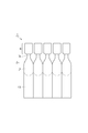
- FIG. 5 Five squeeze bottles were produced in a connected state (FIG. 5), and one squeeze bottle was separated from the connected squeeze bottle and used.
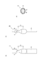
- 4A is a front view showing the configuration of the squeeze bottle produced in Test Example 4
- FIG. 4B is a left side view showing the configuration of the squeeze bottle produced in Test Example 4.
- the squeeze bottle 1 seals the container body 2 including the container 3 and the spout 4 connected to the container 3 and the opening 5 of the spout 4.
- the lid 6 joined to the container body 2 is integrally provided.
- the squeeze bottle according to the present embodiment may include the grip portion 13 at the lower portion of the housing portion 3, as in the squeeze bottle produced in Test Example 4.
- FIG. 5 Five squeeze bottles were produced in a connected state (FIG. 5), and one squeeze bottle was separated from the connected squeeze bottle and used.
- 4A is a front view showing the configuration of the squeeze bottle produced in Test Example 4
- FIG. 4B is a left side view showing the configuration of the squeeze bottle produced in Test Example 4.
- the squeeze bottle 1
- FIG. 4C is a diagram schematically showing a cross section (a cross section along the direction perpendicular to the direction in which the liquid composition is dropped or poured out) of the housing portion of the squeeze bottle produced in Test Example 4.
- the container 3 has a two-layer structure including an outer layer 14 and an inner layer 15 in contact with the liquid composition (purified water) 16, and the liquid composition (purified water) 16 is filled therein.
- the shape of the housing part of each prepared squeeze bottle was 12 mm high, 9.5 mm long diameter (inner diameter), 8 mm short diameter (inner diameter), inner layer thickness 0.1 mm, and outer layer thickness 0.3 mm.
- the cross section (the cross section along the direction perpendicular to the direction in which the liquid composition is dropped or poured out) of the accommodating part of each prepared squeeze bottle was elliptical.
- the opening of each prepared squeeze bottle was circular, and its diameter was 1.5 mm (inner diameter).
- the half distance of the distance between the maximum test force measurement site and the measurement stage was 4.4 mm.
- the compressive strength at the side surface (circumferential surface) of the accommodating portion of the squeeze bottle of each Test Example was calculated. The results are shown in Table 5.
- Test Example 5 Operability evaluation (3)
- a two-layer squeeze bottle of each test example shown in Table 5 was produced in the same manner as in Test Example 4.
- Five adult male subjects grasped and twisted the lid of the squeeze bottle, and opened the opening by separating the lid and the container body.
- the subject dropped a drop of purified water filled in the squeeze bottle from 10 cm above the plane on which the circle with a diameter of 24 mm was placed, targeting the center point of this circle.
- VAS Visual Analog Scale
- the center point of a circle with a diameter of 24 mm overlaps with the center of the dropped liquid after dropping, the drop cannot be dropped on a circle with a diameter of 10 cm and a diameter of 24 mm or one drop.
- the center point of a circle with a diameter of 24 mm and the landing after dropping are the most felt to be 10 cm when the drop cannot be dropped onto a circle with a diameter of 24 mm, or two drops was set to 0 cm when continuous dripping was not possible.
- the average of the VAS values of five subjects was used as the VAS value of the test example.
- the results are shown in Table 5.
- it can evaluate that it is a squeeze bottle excellent in operativity, so that the value which totaled the VAS value about each evaluation item is large.
- the squeeze bottles of Test Examples 1-13 and 1-14 having a resin containing a cyclic olefin copolymer and a linear low-density polyethylene as an inner layer are resins containing a cyclic olefin copolymer but not containing a linear low-density polyethylene. Compared to the squeeze bottle of Test Example 1-12 for the inner layer, it was confirmed that all had low compressive strength and improved operability.
- Test Example 6 Operability evaluation (4)
- two-layer squeeze bottles of Test Examples having different opening areas as shown in Tables 6 and 7 were prepared.
- the area of the opening and 1) only one drop could be dropped on the target site (the center point of a circle with a diameter of 24 mm), 2) two drops in succession on the target site (diameter)
- the VAS value of each test example was calculated with respect to three items, which were able to be dropped on the center point of a circle of 24 mm), and 3) which was able to land on the target point (the center point of a circle having a diameter of 24 mm) at the intended timing. .
- the results are shown in Tables 6 and 7.
- Test Example 7 Operability evaluation (5)
- a two-layer squeeze bottle of each test example shown in Table 8 was produced in the same manner as in Test Example 4.
- the shape of the storage part of each squeeze bottle produced was 12 mm high, 9.5 mm long (inner diameter), 8 mm short diameter (inner diameter), inner layer thickness 0.1 mm, outer layer for Test Examples 3-1 to 3-3.
- the height was 12 mm
- the major axis was 9.5 mm (inner diameter)
- the minor axis was 8 mm (inner diameter)
- the inner layer thickness was 0.2 mm
- the outer layer thickness was 0.2 mm. It was 2 mm.
- vertical to the direction in which a liquid composition is dripped or poured out) of the accommodating part of each produced squeeze bottle was elliptical.
- the opening part of each produced squeeze bottle was circular, and the diameter was 1.5 mm (inner diameter).
- the five subjects 1) grasped and twisted the lid of the squeeze bottle, eased opening of the opening when the lid and the container were separated, and 2) touched the opening after opening with a finger About the smoothness of the time, I answered the questionnaire by the VAS (Visual Analog Scale) method.
- VAS Visual Analog Scale
- each item is defined as 10 cm on the survey sheet on which a straight line of 10 cm is written, and 10 cm on the case of “most felt” and 0 cm on “not feel at all”.
- the test subject was shown a point on the straight line corresponding to, and the distance (cm) from the 0 cm point was measured to obtain the VAS value.
- the average of the VAS values of five subjects was used as the VAS value of the test example.
- the results are shown in Table 8. In addition, it can evaluate that it is a squeeze bottle excellent in operativity, so that the value which totaled the VAS value about each evaluation item is large.
- the squeeze bottles of Test Examples 3-2 to 3 to 5 having a resin containing a cyclic olefin copolymer and a linear low density polyethylene as inner layers are resins containing a cyclic olefin copolymer but not containing a linear low density polyethylene.
- the operability was improved in all cases.
- One of the subjects (subject C) felt almost no resistance when the lid of the squee bottle in Test Example 3-3 was separated from the container (VAS value was 9.5).
- VAS value When subject C stroked the opening of the squeeze bottle of Test Example 3-2 with his / her finger, almost no unevenness was felt (VAS value was 9.0).
- subject C stroked the opening of the squeeze bottle of Test Example 3-1 with a finger he / she felt unevenness and visually observed the unevenness (VAS value was 7.0).
- Test Example 3-2 was 82%
- Test Example 3-3 was 88%
- Test Example 3-4 was 78. %
- Test Example 3-5 was 80%.
- the maximum value of the light transmittance was obtained by measuring the light transmittance every 10 nm between wavelengths of 400 to 700 nm using a microplate reader (SH-9000, manufactured by Corona Electric Co., Ltd.). It calculated
- Test Example 8 Operability evaluation (6)
- a two-layer squeeze bottle of each test example shown in Table 8 was produced in the same manner as in Test Example 4.
- the squeeze bottle housing was emptied.
- SYMBOLS 1 Squeeze bottle, 2 ... Container main body, 3 ... Accommodating part, 3a ... Side surface (circumferential surface) of accommodating part, 3b ... Bottom surface of accommodating part, 4 ... Spout, 5 ... Opening part, 6 ... Cover, 10 ... Maximum A plane on which the container body of the squeeze bottle is placed when measuring the test force, 11 ... a measurement probe, 12 ... a maximum test force measurement site, 13 ... a gripping part, 14 ... an inner layer, 15 ... an outer layer, 16 ... a liquid composition (purified water).
Landscapes
- Health & Medical Sciences (AREA)
- Animal Behavior & Ethology (AREA)
- Public Health (AREA)
- Veterinary Medicine (AREA)
- Pharmacology & Pharmacy (AREA)
- Life Sciences & Earth Sciences (AREA)
- General Health & Medical Sciences (AREA)
- Engineering & Computer Science (AREA)
- Mechanical Engineering (AREA)
- Hematology (AREA)
- Ceramic Engineering (AREA)
- Containers Having Bodies Formed In One Piece (AREA)
- Medical Preparation Storing Or Oral Administration Devices (AREA)
- Closures For Containers (AREA)
- Formation And Processing Of Food Products (AREA)
Abstract
Description
[1]液状組成物を収容するための収容部、及び前記収容部に連設された注出口を含む容器本体と、
前記注出口の開口部を密封するように前記容器本体に接合された蓋と、を一体的に備えるスクイズボトルであって、
前記容器本体は、環状オレフィン類及びポリエチレン類を含有する樹脂を含む、スクイズボトル。
[2]前記注出口の開口部の面積が、0.15~20.0mm2である、[1]に記載のスクイズボトル。
[3]前記収容部の側面における圧縮強度が、20~250N/mmである、[1]又は[2]に記載のスクイズボトル。
[4]前記容器本体の波長400~700nmの可視光領域における光透過率の最大値が、50%以上である、[1]~[3]のいずれかに記載のスクイズボトル。
[5]前記容器本体が内層及び外層を含む2以上の層からなり、前記液状組成物と接する前記内層が環状オレフィン類及びポリエチレン類を含有する樹脂を含む、[1]~[4]のいずれかに記載のスクイズボトル。
[6]前記ポリエチレン類が、低密度ポリエチレン及び/又は直鎖状低密度ポリエチレンである、[1]~[5]のいずれかに記載のスクイズボトル。
[7]前記液状組成物と接する環状オレフィン類及びポリエチレン類を含有する樹脂層における前記環状オレフィン類の総含有量が、前記環状オレフィン類及びポリエチレン類を含有する樹脂の総量を基準として、50~99質量%である、[1]~[6]のいずれかに記載のスクイズボトル。
[8]前記液状組成物が眼科用組成物である、[1]~[7]のいずれかに記載のスクイズボトル。
[9]環状オレフィン類及びポリエチレン類を含有する樹脂を用いて一体的に成形することを含む、スクイズボトルの製造方法。
[10]環状オレフィン類及びポリエチレン類を含有する樹脂を用いて一体的に成形することでスクイズボトルを製造することを含む、該スクイズボトルに収容された液状組成物を吐出する操作性を向上させる方法。
1)注出口4の開口部5が開封され、液状組成物が収容されていないスクイズボトル1を、開口部5が横方向を向くように平面10(例えば、精密万能試験機の測定ステージ)上に置く。
2)収容部の側面(周面)3aにおいて、液状組成物を滴下又は注出するために通常指先で把持する部位12(1箇所;以下、「最大試験力測定部位」ともいう)に測定プローブ11を接触させ、最大試験力測定部位12と平面10との間の距離hの半分の距離(h/2)を100mm/minの速度で押し込む時に要する力の最大値(以下、「最大試験力」ともいう)を測定する。なお、測定プローブ11は、その端面の全てが収容部の側面(周面)3aにおける最大試験力測定部位12と接するようにし、かつ収容部の側面(周面)3aを貫通しないような形状のものを適宜選択する。また、収容部の底面3bは最大試験力を測定する部位とはしない。
3)下記式1に従って、測定した最大試験力を最大試験力測定部位の厚みで除した値(以下、「単位厚み当たりの最大試験力」ともいう)を算出する。
[式1]単位厚み当たりの最大試験力(N/mm)=最大試験力/収容部の側面(周面)における最大試験力を測定した部位の厚み
4)同一の組成及び形状を有する5個のスクイズボトル1について、同一の部位における単位厚み当たりの最大試験力を算出し、得られた5つの値の平均値(以下、「単位厚み当たりの最大試験力の平均値」ともいう)を算出する。
5)スクイズボトル1の収容部の側面(周面)3aにおける複数の最大試験力測定部位12(3箇所以上)について、単位厚み当たりの最大試験力の平均値を算出し、得られた3つ以上の単位厚み当たりの最大試験力の平均値の中で最小の値を「収容部の側面(周面)における圧縮強度」とする。
収容部及び注出口を含む容器本体と蓋とを一体的に備え、表1及び2に示す配合比率で環状オレフィン類とポリエチレン類を含有する樹脂で成形され、精製水5mLが充填された各試験例のスクイズボトルを、ブローフィルシール法で作製した。なお、環状オレフィンコポリマーはTOPAS8007(ポリプラスチックス社製)を使用し、低密度ポリエチレンは密度0.927kg/m3を使用し、直鎖状低密度ポリエチレンは密度0.920kg/m3を使用した。また、作製した各スクイズボトルの収容部の形状は、高さ38mm、長径20mm(外径)、短径13mm(外径)、厚み約500μmであった。
上記各試験例のスクイズボトルの蓋を把持して捩じり、蓋と容器本体を切り離して開口部を開封した後、スクイズボトルに充填された精製水を開口部から排出して、スクイズボトルの収容部を空にした。開口部は円形で、その直径は1.5mm(内径)であった。
精密万能試験機(オートグラフAGS-X、島津製作所製)を用いて、各スクイズボトルの収容部の側面(周面)の圧縮強度を測定した。スクイズボトルを、開口部5が横方向を向くように精密万能試験機の測定ステージ上に置いた。最大試験力測定部位として収容部側面(周面)の中央部(1箇所)に測定プローブ(先端の直径3mmの円柱形;ステンレス製)の全面を接触させ、最大試験力測定部位と測定ステージとの間の距離(短径13mm)の半分の距離(6.5mm)を100mm/minの速度で押し込んだ時の最大試験力(N)を測定した。また、収容部側面(周面)の最大試験力測定部位の厚みを、ノギスを用いて計測した。下記式1に従って、単位厚み当たりの最大試験力を算出した。これを1つの試験例について5個のスクイズボトルで行い、単位厚み当たりの最大試験力の平均値を算出した。スクイズボトルの収容部における、異なる3箇所の最大試験力測定部位について、単位厚み当たりの最大試験力の平均値を算出し、得られた3つの単位厚み当たりの最大試験力の平均値の中で最小の値を、試験例の収容部の側面(周面)における圧縮強度とした。圧縮試験は、室温23℃、湿度50%の条件で実施した。結果を表1及び2に示す。
[式1]単位厚み当たりの最大試験力(N/mm)=最大試験力/収容部の側面(周面)における最大試験力を測定した部位の厚み
試験例1と同様の方法で、表1及び2に示す各試験例のスクイズボトルを作製した。
4名の被験者は、スクイズボトルの蓋を把持して捩じり、蓋と容器本体を切り離すことで開口部を開封した。開口部の直径は1.5mm(内径)であった。次に被験者は、スクイズボトルに充填された精製水を、直径24mmの円が置かれた平面に対して10cm上方から、この円の中心点を標的として液滴を滴下した。その操作性についてVAS(Visual Analog Scale)法によるアンケートに回答した。被験者は、アンケートで指示された滴数を滴下するように試みた。具体的には、1)1滴のみ滴下できた、2)連続して2滴を滴下できた、及び3)意図したタイミングで標的点(直径24mmの円の中心点)に着滴できた、の3項目について、10cmの直線が記載された調査シート上に、「最も感じる場合」を10cm、「全く感じられない場合」を0cmとして、上記各項目に相当する直線上の点を被験者に示させ、0cmの点からの距離(cm)を測定し、VAS値とした。なお、意図したタイミングとは、収容部を押し始めて1秒後に着滴するように操作を行うことを意味する。4名の被験者のVAS値の平均を、試験例のVAS値とした。結果を表1及び2に示す。なお、各評価項目についてのVAS値を合計した値が大きいほど、操作性に優れたスクイズボトルであると評価できる。


収容部及び注出口を含む容器本体と蓋とを一体的に備え、表3及び4に示す配合比率で環状オレフィン類とポリエチレン類を含有する樹脂で成形され、精製水5mLが充填された、開口部の面積が異なる各試験例のスクイズボトルを、ブローフィルシール法で作製した。なお、環状オレフィンコポリマーはTOPAS8007(ポリプラスチックス社製)を使用し、低密度ポリエチレンは密度0.927kg/m3を使用し、直鎖状低密度ポリエチレンは密度0.920kg/m3を使用した。作製した各スクイズボトルの収容部の形状は、高さ38mm、厚み約500μmであった。
被験者は、スクイズボトルの蓋を把持して捩じり、蓋と収容部を切り離すことで開口部を開封した。次に被験者は、スクイズボトルに充填された精製水を、直径24mmの円が置かれた平面に対して10cm上方から、この円の中心点を標的として液滴を滴下した。その操作性についてVAS(Visual Analog Scale)法によるアンケートに回答した。被験者は、アンケートで指示された滴数を滴下するように試みた。具体的には、1)1滴のみ滴下できた、2)連続して2滴を滴下できた、及び3)意図したタイミングで標的点(直径24mmの円の中心点)に着滴できた、の3項目について、10cmの直線が記載された調査シート上に、「最も感じる場合」を10cm、「全く感じられない場合」を0cmとして、上記各項目に相当する直線上の点を被験者に示させ、0cmの点からの距離(cm)を測定し、VAS値とした。なお、各評価項目についてのVAS値を合計した値が大きいほど、操作性に優れたスクイズボトルであると評価できる。また、開口部の面積は、万能投影機(PROFILE PROJECTOR V-12B、Nikon社製)を用いて、長径と短径を計測することで算出した。


収容部及び注出口を含む容器本体と蓋とを一体的に備え、環状オレフィンコポリマー(TOPAS8007(ポリプラスチックス社製))と直鎖状低密度ポリエチレン(密度0.920kg/m3)を表5に示す配合比率で含有する樹脂を内層とし、低密度ポリエチレン(密度0.927kg/m3)を外層とした、液状組成物(精製水)が0.5mL充填された各試験例の2層のスクイズボトル1を、ブローフィルシール法で作製した(図4)。スクイズボトルは5個連結した状態で作製され(図5)、当該連結したスクイズボトルから1個のスクイズボトルを切り離して使用した。
図4(a)は、試験例4で作製されたスクイズボトルの構成を示す正面図であり、図4(b)は、試験例4で作製されたスクイズボトルの構成を示す左側面図である。図4(a)及び(b)に示すように、スクイズボトル1は、収容部3及び収容部3に連設された注出口4を含む容器本体2と、注出口4の開口部5を密封するように容器本体2に接合された蓋6とを一体的に備えている。なお、本実施形態に係るスクイズボトルは、試験例4で作製されたスクイズボトルのように、把持部13を収容部3の下部に備えていてもよい。
図4(c)は、試験例4で作製されたスクイズボトルの収容部の断面(液状組成物が滴下又は注出される方向と垂直の方向に沿った断面)を模式的に示した図である。図4(c)に示すように、収容部3は外層14及び液状組成物(精製水)16と接する内層15からなる2層構造であり、内部に液状組成物(精製水)16が充填されている。
作製した各スクイズボトルの収容部の形状は、高さ12mm、長径9.5mm(内径)、短径8mm(内径)、内層の厚み0.1mm、外層の厚み0.3mmであった。作製した各スクイズボトルの収容部の断面(液状組成物が滴下又は注出される方向と垂直の方向に沿った断面)は楕円形であった。作製した各スクイズボトルの開口部は円形で、その直径は1.5mm(内径)であった。
次いで、最大試験力測定部位と測定ステージとの間の距離(短径の内径8mm、内層の厚み0.1mm、外層の厚み0.3mm)の半分の距離が4.4mmであったこと以外は試験例1と同様の方法で、各試験例のスクイズボトルの収容部側面(周面)における圧縮強度を算出した。結果を表5に示す。
試験例4と同様の方法で、表5に示す各試験例の2層のスクイズボトルを作製した。
5名の成人男性被験者は、スクイズボトルの蓋を把持して捩じり、蓋と容器本体を切り離すことで開口部を開封した。次に被験者は、スクイズボトルに充填された精製水を、直径24mmの円が置かれた平面に対して10cm上方から、この円の中心点を標的として液滴を滴下した。その操作性についてVAS(Visual Analog Scale)法によるアンケートに回答した。被験者は、アンケートで指示された滴数を滴下するように試みた。具体的には、1)1滴のみ標的部位(直径24mmの円の中心点)に滴下できた、2)連続した2滴を標的部位(直径24mmの円の中心点)に滴下できた、及び3)意図したタイミングで標的点(直径24mmの円の中心点)に着滴できた、の3項目について、10cmの直線が記載された調査シート上に、「最も感じる場合」を10cm、「全く感じられない場合」を0cmとして、上記各項目に相当する直線上の点を被験者に示させ、0cmの点からの距離(cm)を測定し、VAS値とした。より具体的には、1)の評価では直径24mmの円の中心点と滴下後の着滴液の中心が重なったと最も感じた場合に10cm、直径24mmの円に滴下できなかった場合又は1滴のみを滴下できなかった(例えば、滴状に吐出しなかった)場合に0cmとし、2)の評価では連続して滴下した2滴のうち、直径24mmの円の中心点と滴下後の着滴液の中心がより離れた1滴について、直径24mmの円の中心点と滴下後の着滴液の中心が重なったと最も感じた場合に10cm、直径24mmの円に滴下できなかった場合又は2滴を連続して滴下できなかった場合に0cmとした。5名の被験者のVAS値の平均を、試験例のVAS値とした。結果を表5に示す。なお、各評価項目についてのVAS値を合計した値が大きいほど、操作性に優れたスクイズボトルであると評価できる。

試験例4と同様の方法で、表6及び7に示す、開口部の面積が異なる各試験例の2層のスクイズボトルを作製した。
次いで、試験例5と同様の方法で、開口部の面積、並びに1)1滴のみ標的部位(直径24mmの円の中心点)に滴下できた、2)連続して2滴を標的部位(直径24mmの円の中心点)に滴下できた、及び3)意図したタイミングで標的点(直径24mmの円の中心点)に着滴できた、の3項目について、各試験例のVAS値を算出した。結果を表6及び7に示す。


試験例4と同様の方法で、表8に示す各試験例の2層のスクイズボトルを作製した。作製した各スクイズボトルの収容部の形状は、試験例3-1~3-3については高さ12mm、長径9.5mm(内径)、短径8mm(内径)、内層の厚み0.1mm、外層の厚み0.3mmであり、試験例3-4及び3-5については高さ12mm、長径9.5mm(内径)、短径8mm(内径)、内層の厚み0.2mm、外層の厚み0.2mmであった。また、作製した各スクイズボトルの収容部の断面(液状組成物が滴下又は注出される方向と垂直の方向に沿った断面)は楕円形であった。さらに、作製した各スクイズボトルの開口部は円形で、その直径は1.5mm(内径)であった。
5名の被験者は、1)スクイズボトルの蓋を把持して捩じり、蓋と収容部を切り離したときの開口部の開封のしやすさ、2)開封後の開口部を指で触れたときの滑らかさ、についてVAS(Visual Analog Scale)法によるアンケートに回答した。具体的には、上記1)及び2)の2項目について、10cmの直線が記載された調査シート上に、「最も感じる場合」を10cm、「全く感じられない場合」を0cmとして、上記各項目に相当する直線上の点を被験者に示させ、0cmの点からの距離(cm)を測定し、VAS値とした。5名の被験者のVAS値の平均を、試験例のVAS値とした。結果を表8に示す。なお、各評価項目についてのVAS値を合計した値が大きいほど、操作性に優れたスクイズボトルであると評価できる。

試験例4と同様の方法で、表8に示す各試験例の2層のスクイズボトルを作製した。5名の成人男性被験者は、各試験例のスクイズボトルの蓋を把持して捩じり、蓋と容器本体を切り離して開口部を開封した後、スクイズボトルに充填された精製水を開口部から排出して、スクイズボトルの収容部を空にした。次いで、各被験者は収容部の断面短径方向の右側面(右周面)中央部及び左側面(左周面)中央部の2部位を2本の指先で把持し、当該2部位から容器の中心に向かって、当該2部位間の距離が4mmになるまで押し込み、当該押し込みが完了してから1秒経過後に収容部から2本の指を離した。指を離した時点を基準とし、目視で観察して、1)当該押し込みによって収容部に凹みが生じた部分が元の形状に戻り始める時間、及び2)元の形状に完全に戻るまでの時間をそれぞれ計測した。各被験者は3個のスクイズボトルについて試験を行い、計測した1)と2)のそれぞれの時間の平均を算出した。表9の評価基準に従って点数を付け、1)と2)の点数の合計を算出した。5名の被験者の結果を平均し、スクイズボトルの弾性の良さとした。結果を表10に示す。なお、点数が大きいほど、弾性が良く、使用者が液状組成物を繰り返し吐出する操作を制御しやすく、操作性に優れたスクイズボトルであると評価できる。


Claims (8)
- 液状組成物を収容するための収容部、及び前記収容部に連設された注出口を含む容器本体と、
前記注出口の開口部を密封するように前記容器本体に接合された蓋と、を一体的に備えるスクイズボトルであって、
前記容器本体は、環状オレフィン類及びポリエチレン類を含有する樹脂を含む、スクイズボトル。 - 前記注出口の開口部の面積が、0.15~20.0mm2である、請求項1に記載のスクイズボトル。
- 前記収容部の側面における圧縮強度が、20~250N/mmである、請求項1又は2に記載のスクイズボトル。
- 前記容器本体の波長400~700nmの可視光領域における光透過率の最大値が、50%以上である、請求項1~3のいずれか1項に記載のスクイズボトル。
- 前記容器本体が内層及び外層を含む2以上の層からなり、前記液状組成物と接する前記内層が環状オレフィン類及びポリエチレン類を含有する樹脂を含む、請求項1~4のいずれか1項に記載のスクイズボトル。
- 前記ポリエチレン類が、低密度ポリエチレン及び/又は直鎖状低密度ポリエチレンである、請求項1~5のいずれか1項に記載のスクイズボトル。
- 前記液状組成物と接する環状オレフィン類及びポリエチレン類を含有する樹脂層における前記環状オレフィン類の総含有量が、前記環状オレフィン類及びポリエチレン類を含有する樹脂の総量を基準として、50~99質量%である、請求項1~6のいずれか1項に記載のスクイズボトル。
- 前記液状組成物が眼科用組成物である、請求項1~7のいずれか1項に記載のスクイズボトル。
Priority Applications (8)
| Application Number | Priority Date | Filing Date | Title |
|---|---|---|---|
| PL18785062.3T PL3610841T3 (pl) | 2017-04-13 | 2018-04-13 | Butelka do wyciskania |
| CN202210581614.8A CN114948721A (zh) | 2017-04-13 | 2018-04-13 | 挤压瓶 |
| CN201880024369.2A CN110505861B (zh) | 2017-04-13 | 2018-04-13 | 挤压瓶 |
| KR1020197033181A KR102584247B1 (ko) | 2017-04-13 | 2018-04-13 | 스퀴즈 보틀 |
| US16/603,956 US11167889B2 (en) | 2017-04-13 | 2018-04-13 | Squeeze bottle |
| EP18785062.3A EP3610841B1 (en) | 2017-04-13 | 2018-04-13 | Squeeze bottle |
| JP2019512581A JP7253487B2 (ja) | 2017-04-13 | 2018-04-13 | スクイズボトル |
| JP2023020192A JP2023054088A (ja) | 2017-04-13 | 2023-02-13 | スクイズボトル |
Applications Claiming Priority (2)
| Application Number | Priority Date | Filing Date | Title |
|---|---|---|---|
| JP2017-080068 | 2017-04-13 | ||
| JP2017080068 | 2017-04-13 |
Publications (1)
| Publication Number | Publication Date |
|---|---|
| WO2018190422A1 true WO2018190422A1 (ja) | 2018-10-18 |
Family
ID=63793461
Family Applications (1)
| Application Number | Title | Priority Date | Filing Date |
|---|---|---|---|
| PCT/JP2018/015546 WO2018190422A1 (ja) | 2017-04-13 | 2018-04-13 | スクイズボトル |
Country Status (8)
| Country | Link |
|---|---|
| US (1) | US11167889B2 (ja) |
| EP (1) | EP3610841B1 (ja) |
| JP (2) | JP7253487B2 (ja) |
| KR (1) | KR102584247B1 (ja) |
| CN (2) | CN110505861B (ja) |
| PL (1) | PL3610841T3 (ja) |
| TW (1) | TWI791510B (ja) |
| WO (1) | WO2018190422A1 (ja) |
Cited By (4)
| Publication number | Priority date | Publication date | Assignee | Title |
|---|---|---|---|---|
| WO2020116654A1 (ja) * | 2018-12-07 | 2020-06-11 | 藤森工業株式会社 | 点眼剤容器 |
| WO2021079405A1 (ja) * | 2019-10-21 | 2021-04-29 | ロート製薬株式会社 | 樹脂製容器及び樹脂製容器連結体 |
| WO2021079404A1 (ja) * | 2019-10-21 | 2021-04-29 | ロート製薬株式会社 | 樹脂製容器及び樹脂製容器連結体 |
| WO2021149712A1 (ja) * | 2020-01-21 | 2021-07-29 | 藤森工業株式会社 | ノズルを構成する中栓及び点眼剤容器 |
Families Citing this family (5)
| Publication number | Priority date | Publication date | Assignee | Title |
|---|---|---|---|---|
| CN111615409A (zh) | 2017-11-17 | 2020-09-01 | 科斯卡家族有限公司 | 用于流体输送歧管的系统和方法 |
| WO2020125819A1 (es) * | 2018-12-21 | 2020-06-25 | John Alexander Botero | Botella abre fácil monodosis multicapa con una configuración pe/pet/pp y un precorte en la parte superior |
| CN112976543B (zh) * | 2021-02-05 | 2023-01-10 | 抚州市医宝城医疗器械有限公司 | 一种用于生产连排塑料安剖瓶的生产工艺、模具及产品 |
| US20220387256A1 (en) * | 2021-06-03 | 2022-12-08 | Kent Byron | Vial With Metered Dispenser |
| USD992110S1 (en) | 2021-08-10 | 2023-07-11 | Koska Family Limited | Sealed fluid container |
Citations (5)
| Publication number | Priority date | Publication date | Assignee | Title |
|---|---|---|---|---|
| JPH05293159A (ja) * | 1991-07-22 | 1993-11-09 | Daikyo Seiko:Kk | 衛生品用容器 |
| JPH07257538A (ja) * | 1994-03-28 | 1995-10-09 | Toppan Printing Co Ltd | プラスチック容器 |
| JP2001157704A (ja) * | 1999-12-02 | 2001-06-12 | Toppan Printing Co Ltd | 輸液用包装材料及びそれを用いた輸液用包装体 |
| WO2004093775A1 (ja) | 2003-04-23 | 2004-11-04 | Otsuka Pharmaceutical Factory, Inc. | 薬液充填プラスチックアンプルおよびその製造方法 |
| WO2009113117A1 (en) * | 2008-03-11 | 2009-09-17 | Buffoli Transfer S.P.A. | Multispindle tool machine |
Family Cites Families (13)
| Publication number | Priority date | Publication date | Assignee | Title |
|---|---|---|---|---|
| US3187966A (en) * | 1963-07-09 | 1965-06-08 | Continental Can Co | Flexible container with snip-off and reseal features |
| US3727803A (en) * | 1969-04-08 | 1973-04-17 | J Campbell | Containers |
| US3993223A (en) * | 1974-07-25 | 1976-11-23 | American Home Products Corporation | Dispensing container |
| JPS5293159A (en) * | 1976-01-30 | 1977-08-05 | Nippon Telegr & Teleph Corp <Ntt> | Method for constructing main part of manhole |
| US5048727A (en) * | 1984-11-02 | 1991-09-17 | Alcon Laboratories, Inc. | Preassembled unit dose dispenser having a compressible container and a tube prefilled with a unit dose of opthalmic gel. |
| US5361947A (en) * | 1993-03-08 | 1994-11-08 | Merck & Co., Inc. | Single use fluid dispensing device |
| DE10049392A1 (de) * | 1999-10-14 | 2001-04-19 | Becton Dickinson Co | Flüssigkeits-Ausgabevorrichtung |
| US6343717B1 (en) * | 2000-11-21 | 2002-02-05 | Jack Yongfeng Zhang | Pre-filled disposable pipettes |
| US6838523B2 (en) * | 2002-10-31 | 2005-01-04 | Sonoco Development, Inc. | Composition for molding thin-walled parts, and injection-molded squeeze tube made thereof |
| CN100515381C (zh) * | 2003-04-23 | 2009-07-22 | 株式会社大塚制药工厂 | 填充了药液的塑料安瓿及其制造方法 |
| WO2010134590A1 (ja) * | 2009-05-22 | 2010-11-25 | 大塚製薬株式会社 | 点眼容器 |
| JP5698503B2 (ja) * | 2010-11-26 | 2015-04-08 | ポリプラスチックス株式会社 | 自立性袋及び自立性袋を減容化する方法 |
| WO2013051686A1 (ja) * | 2011-10-07 | 2013-04-11 | 三菱瓦斯化学株式会社 | 医療用包装容器 |
-
2018
- 2018-04-13 CN CN201880024369.2A patent/CN110505861B/zh active Active
- 2018-04-13 TW TW107112955A patent/TWI791510B/zh active
- 2018-04-13 CN CN202210581614.8A patent/CN114948721A/zh active Pending
- 2018-04-13 JP JP2019512581A patent/JP7253487B2/ja active Active
- 2018-04-13 WO PCT/JP2018/015546 patent/WO2018190422A1/ja unknown
- 2018-04-13 PL PL18785062.3T patent/PL3610841T3/pl unknown
- 2018-04-13 KR KR1020197033181A patent/KR102584247B1/ko active IP Right Grant
- 2018-04-13 US US16/603,956 patent/US11167889B2/en active Active
- 2018-04-13 EP EP18785062.3A patent/EP3610841B1/en active Active
-
2023
- 2023-02-13 JP JP2023020192A patent/JP2023054088A/ja active Pending
Patent Citations (6)
| Publication number | Priority date | Publication date | Assignee | Title |
|---|---|---|---|---|
| JPH05293159A (ja) * | 1991-07-22 | 1993-11-09 | Daikyo Seiko:Kk | 衛生品用容器 |
| JPH07257538A (ja) * | 1994-03-28 | 1995-10-09 | Toppan Printing Co Ltd | プラスチック容器 |
| JP2001157704A (ja) * | 1999-12-02 | 2001-06-12 | Toppan Printing Co Ltd | 輸液用包装材料及びそれを用いた輸液用包装体 |
| WO2004093775A1 (ja) | 2003-04-23 | 2004-11-04 | Otsuka Pharmaceutical Factory, Inc. | 薬液充填プラスチックアンプルおよびその製造方法 |
| JP2012135621A (ja) * | 2003-04-23 | 2012-07-19 | Otsuka Pharmaceut Factory Inc | 薬液充填プラスチックアンプルおよびその製造方法 |
| WO2009113117A1 (en) * | 2008-03-11 | 2009-09-17 | Buffoli Transfer S.P.A. | Multispindle tool machine |
Cited By (11)
| Publication number | Priority date | Publication date | Assignee | Title |
|---|---|---|---|---|
| WO2020116654A1 (ja) * | 2018-12-07 | 2020-06-11 | 藤森工業株式会社 | 点眼剤容器 |
| CN113302133A (zh) * | 2018-12-07 | 2021-08-24 | 藤森工业株式会社 | 滴眼剂容器 |
| JPWO2020116654A1 (ja) * | 2018-12-07 | 2021-10-28 | 藤森工業株式会社 | 点眼剤容器 |
| WO2021079405A1 (ja) * | 2019-10-21 | 2021-04-29 | ロート製薬株式会社 | 樹脂製容器及び樹脂製容器連結体 |
| WO2021079404A1 (ja) * | 2019-10-21 | 2021-04-29 | ロート製薬株式会社 | 樹脂製容器及び樹脂製容器連結体 |
| CN114585566A (zh) * | 2019-10-21 | 2022-06-03 | 乐敦制药株式会社 | 树脂制容器及树脂制容器连结体 |
| CN114585565A (zh) * | 2019-10-21 | 2022-06-03 | 乐敦制药株式会社 | 树脂制容器及树脂制容器连结体 |
| EP4049939A4 (en) * | 2019-10-21 | 2023-08-02 | Rohto Pharmaceutical Co., Ltd. | RESIN CONTAINER AND CROSS-LINKED RESIN CONTAINER ARTICLE |
| EP4049938A4 (en) * | 2019-10-21 | 2023-08-02 | Rohto Pharmaceutical Co., Ltd. | RESIN CONTAINER AND CONNECTING BODY FOR RESIN CONTAINERS |
| WO2021149712A1 (ja) * | 2020-01-21 | 2021-07-29 | 藤森工業株式会社 | ノズルを構成する中栓及び点眼剤容器 |
| JP2021113088A (ja) * | 2020-01-21 | 2021-08-05 | 藤森工業株式会社 | ノズルを構成する中栓及び点眼剤容器 |
Also Published As
| Publication number | Publication date |
|---|---|
| EP3610841A1 (en) | 2020-02-19 |
| JP7253487B2 (ja) | 2023-04-06 |
| EP3610841A4 (en) | 2020-12-30 |
| CN114948721A (zh) | 2022-08-30 |
| KR102584247B1 (ko) | 2023-10-04 |
| CN110505861B (zh) | 2022-06-14 |
| JP2023054088A (ja) | 2023-04-13 |
| CN110505861A (zh) | 2019-11-26 |
| TWI791510B (zh) | 2023-02-11 |
| KR20190138669A (ko) | 2019-12-13 |
| US20200122898A1 (en) | 2020-04-23 |
| JPWO2018190422A1 (ja) | 2020-02-27 |
| PL3610841T3 (pl) | 2023-05-02 |
| EP3610841B1 (en) | 2023-01-04 |
| US11167889B2 (en) | 2021-11-09 |
| TW201841597A (zh) | 2018-12-01 |
Similar Documents
| Publication | Publication Date | Title |
|---|---|---|
| WO2018190422A1 (ja) | スクイズボトル | |
| US7563256B2 (en) | Cannula tip eye drop dispenser | |
| WO2001012125A1 (fr) | Element encastre formant un conteneur d'instillation | |
| JP6008254B2 (ja) | プラスチックアンプル | |
| CN105263449B (zh) | 稳定性提高的点眼药器和将液体滴加到眼睛表面上的方法 | |
| CN102666301A (zh) | 用于眼用溶液的容器的封盖 | |
| WO2021079404A1 (ja) | 樹脂製容器及び樹脂製容器連結体 | |
| CN115697131A (zh) | 单触接触镜片包装件 | |
| CN101455600A (zh) | 活塞式眼药水滴注装置 | |
| JP7249123B2 (ja) | 樹脂製容器 | |
| JP7360238B2 (ja) | 樹脂製のブロー・フィル・シール成形容器 | |
| JP7398267B2 (ja) | 点眼剤容器 | |
| WO2021079405A1 (ja) | 樹脂製容器及び樹脂製容器連結体 | |
| JP7477319B2 (ja) | ノズルを構成する中栓及び点眼剤容器 | |
| JPWO2017217450A1 (ja) | 眼科用医薬製品 | |
| CN103655183B (zh) | 一次性单剂量容器及包装 | |
| TW202116541A (zh) | 樹脂製容器及樹脂製容器連結體 | |
| WO2022043743A1 (en) | An apparatus for facilitating self-administration of eye drops | |
| CA2852015A1 (en) | Liquid dispenser |
Legal Events
| Date | Code | Title | Description |
|---|---|---|---|
| 121 | Ep: the epo has been informed by wipo that ep was designated in this application |
Ref document number: 18785062 Country of ref document: EP Kind code of ref document: A1 |
|
| ENP | Entry into the national phase |
Ref document number: 2019512581 Country of ref document: JP Kind code of ref document: A |
|
| NENP | Non-entry into the national phase |
Ref country code: DE |
|
| ENP | Entry into the national phase |
Ref document number: 20197033181 Country of ref document: KR Kind code of ref document: A |
|
| ENP | Entry into the national phase |
Ref document number: 2018785062 Country of ref document: EP Effective date: 20191113 |