WO2018190107A1 - 監視システム - Google Patents
監視システム Download PDFInfo
- Publication number
- WO2018190107A1 WO2018190107A1 PCT/JP2018/011968 JP2018011968W WO2018190107A1 WO 2018190107 A1 WO2018190107 A1 WO 2018190107A1 JP 2018011968 W JP2018011968 W JP 2018011968W WO 2018190107 A1 WO2018190107 A1 WO 2018190107A1
- Authority
- WO
- WIPO (PCT)
- Prior art keywords
- circuit
- output terminal
- voltage
- unit
- monitoring
- Prior art date
- Legal status (The legal status is an assumption and is not a legal conclusion. Google has not performed a legal analysis and makes no representation as to the accuracy of the status listed.)
- Ceased
Links
Images


Classifications
-
- B—PERFORMING OPERATIONS; TRANSPORTING
- B60—VEHICLES IN GENERAL
- B60L—PROPULSION OF ELECTRICALLY-PROPELLED VEHICLES; SUPPLYING ELECTRIC POWER FOR AUXILIARY EQUIPMENT OF ELECTRICALLY-PROPELLED VEHICLES; ELECTRODYNAMIC BRAKE SYSTEMS FOR VEHICLES IN GENERAL; MAGNETIC SUSPENSION OR LEVITATION FOR VEHICLES; MONITORING OPERATING VARIABLES OF ELECTRICALLY-PROPELLED VEHICLES; ELECTRIC SAFETY DEVICES FOR ELECTRICALLY-PROPELLED VEHICLES
- B60L3/00—Electric devices on electrically-propelled vehicles for safety purposes; Monitoring operating variables, e.g. speed, deceleration or energy consumption
-
- B—PERFORMING OPERATIONS; TRANSPORTING
- B60—VEHICLES IN GENERAL
- B60L—PROPULSION OF ELECTRICALLY-PROPELLED VEHICLES; SUPPLYING ELECTRIC POWER FOR AUXILIARY EQUIPMENT OF ELECTRICALLY-PROPELLED VEHICLES; ELECTRODYNAMIC BRAKE SYSTEMS FOR VEHICLES IN GENERAL; MAGNETIC SUSPENSION OR LEVITATION FOR VEHICLES; MONITORING OPERATING VARIABLES OF ELECTRICALLY-PROPELLED VEHICLES; ELECTRIC SAFETY DEVICES FOR ELECTRICALLY-PROPELLED VEHICLES
- B60L15/00—Methods, circuits, or devices for controlling the traction-motor speed of electrically-propelled vehicles
- B60L15/20—Methods, circuits, or devices for controlling the traction-motor speed of electrically-propelled vehicles for control of the vehicle or its driving motor to achieve a desired performance, e.g. speed, torque, programmed variation of speed
-
- B—PERFORMING OPERATIONS; TRANSPORTING
- B60—VEHICLES IN GENERAL
- B60L—PROPULSION OF ELECTRICALLY-PROPELLED VEHICLES; SUPPLYING ELECTRIC POWER FOR AUXILIARY EQUIPMENT OF ELECTRICALLY-PROPELLED VEHICLES; ELECTRODYNAMIC BRAKE SYSTEMS FOR VEHICLES IN GENERAL; MAGNETIC SUSPENSION OR LEVITATION FOR VEHICLES; MONITORING OPERATING VARIABLES OF ELECTRICALLY-PROPELLED VEHICLES; ELECTRIC SAFETY DEVICES FOR ELECTRICALLY-PROPELLED VEHICLES
- B60L3/00—Electric devices on electrically-propelled vehicles for safety purposes; Monitoring operating variables, e.g. speed, deceleration or energy consumption
- B60L3/04—Cutting off the power supply under fault conditions
-
- G—PHYSICS
- G01—MEASURING; TESTING
- G01R—MEASURING ELECTRIC VARIABLES; MEASURING MAGNETIC VARIABLES
- G01R31/00—Arrangements for testing electric properties; Arrangements for locating electric faults; Arrangements for electrical testing characterised by what is being tested not provided for elsewhere
- G01R31/36—Arrangements for testing, measuring or monitoring the electrical condition of accumulators or electric batteries, e.g. capacity or state of charge [SoC]
- G01R31/382—Arrangements for monitoring battery or accumulator variables, e.g. SoC
- G01R31/3835—Arrangements for monitoring battery or accumulator variables, e.g. SoC involving only voltage measurements
-
- Y—GENERAL TAGGING OF NEW TECHNOLOGICAL DEVELOPMENTS; GENERAL TAGGING OF CROSS-SECTIONAL TECHNOLOGIES SPANNING OVER SEVERAL SECTIONS OF THE IPC; TECHNICAL SUBJECTS COVERED BY FORMER USPC CROSS-REFERENCE ART COLLECTIONS [XRACs] AND DIGESTS
- Y02—TECHNOLOGIES OR APPLICATIONS FOR MITIGATION OR ADAPTATION AGAINST CLIMATE CHANGE
- Y02T—CLIMATE CHANGE MITIGATION TECHNOLOGIES RELATED TO TRANSPORTATION
- Y02T10/00—Road transport of goods or passengers
- Y02T10/60—Other road transportation technologies with climate change mitigation effect
- Y02T10/70—Energy storage systems for electromobility, e.g. batteries
-
- Y—GENERAL TAGGING OF NEW TECHNOLOGICAL DEVELOPMENTS; GENERAL TAGGING OF CROSS-SECTIONAL TECHNOLOGIES SPANNING OVER SEVERAL SECTIONS OF THE IPC; TECHNICAL SUBJECTS COVERED BY FORMER USPC CROSS-REFERENCE ART COLLECTIONS [XRACs] AND DIGESTS
- Y02—TECHNOLOGIES OR APPLICATIONS FOR MITIGATION OR ADAPTATION AGAINST CLIMATE CHANGE
- Y02T—CLIMATE CHANGE MITIGATION TECHNOLOGIES RELATED TO TRANSPORTATION
- Y02T10/00—Road transport of goods or passengers
- Y02T10/60—Other road transportation technologies with climate change mitigation effect
- Y02T10/72—Electric energy management in electromobility
Definitions
- This invention relates to the monitoring system which monitors the electrical storage part mounted in the vehicle.
- Patent Document 1 includes a main detection circuit and a sub detection circuit for detecting a voltage of a storage cell, a main detection line for connecting the storage cell to the main detection circuit, and a sub detection line for connecting the storage cell to the sub detection circuit.
- a monitoring device is disclosed.
- the main detection line and the sub detection line are configured by separate wiring so that at least a part thereof is electrically independent.
- the main detection circuit is controlled by the main microcomputer, and the sub detection circuit is controlled by the sub microcomputer.
- the main microcomputer determines whether or not the main detection line is disconnected, and the sub microcomputer determines whether or not the sub detection line is disconnected.
- the main microcomputer system and the sub microcomputer system have independent configurations including the detection lines connected to the storage cells, and the redundancy increases, but the circuit complexity also increases. There is a problem that the circuit scale becomes large.
- the present invention has been made in view of such circumstances, and an object of the present invention is to provide a monitoring system capable of improving the vehicle continuity while suppressing an increase in circuit scale for monitoring the power storage unit. It is to provide.
- a monitoring system detects a voltage of a power storage unit mounted on a vehicle, outputs a detected voltage together with its own circuit failure information, and whether or not the detected voltage is abnormal
- a voltage detection unit having a second output terminal for outputting a voltage abnormality signal indicating the above, and a first monitoring unit connected to the first output terminal and acquiring voltage output from the first output terminal and circuit fault information
- a second monitoring unit that is connected to the second output terminal and acquires a voltage abnormality signal output from the second output terminal, and a power storage unit based on notifications from the first monitoring unit and the second monitoring unit
- a traveling control unit that cuts off the electrical connection of the traveling motor, and the traveling control unit has a circuit failure in both the circuit on the first output terminal side and the circuit on the second output terminal side, Connect the power storage unit and travel motor. Cross and, while there is circuit failure, there is no circuit failure in the other, and, when power storage unit is normal, the power storage unit and the traction motor connected state.
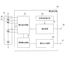
- FIG. 1 is a block diagram illustrating a configuration of a monitoring system 100 according to the embodiment.
- the monitoring system 100 includes a monitoring unit 1, a travel control unit 70, and a relay 71.
- the traveling control unit 70 controls the relay 71 based on the signal input from the monitoring unit 1.
- the traveling control unit 70 also monitors the state of the power storage unit 6 mounted on the vehicle and controls the driving of the traveling motor 8 by the power storage unit 6.
- the power storage unit 6 is formed by connecting a plurality of power storage cells 61 (see FIG. 2), for example, lithium ion battery cells in series.
- the storage cell 61 may be a nickel hydrogen battery cell, a lead battery cell, an electric double layer capacitor cell, a lithium ion capacitor cell, or the like.
- the monitoring unit 1 includes a plurality of voltage detection units 10, a first monitoring unit 20, and a second monitoring unit 30.
- the voltage detection unit 10 detects the voltage of the power storage unit 6, detects whether there is an abnormality due to overcharge or overdischarge, and outputs it to the first monitoring unit 20 and the second monitoring unit 30.
- the first monitoring unit 20 notifies the traveling control unit 70 of the presence / absence of an abnormality in the power storage unit 6 and the presence / absence of a circuit failure in the voltage detection unit 10, and the second monitoring unit 30 indicates the presence / absence of an abnormality in the power storage unit 6. 70 is notified.
- the traveling control unit 70 opens and closes the relay 71 based on the notifications from the first monitoring unit 20 and the second monitoring unit 30 to control electrical connection / disconnection between the power storage unit 6 and the traveling motor 8. 8 is driven.
- FIG. 2 is a block diagram illustrating a configuration of the voltage detection unit 10.
- the voltage detection unit 10 includes a voltage detection circuit 11 that detects the voltage of the power storage unit 6, an abnormality detection circuit 12, a communication circuit 13, a terminal output circuit 14, and a circuit failure detection unit 15.
- an ASIC Application Specific Integrated Circuit
- the voltage detection circuit 11 detects the voltage of the power storage unit 6 formed by connecting a plurality of power storage cells 61 in series, or detects two or more adjacent power storage cells 61 as a block. To do.
- the abnormality detection circuit 12 compares the voltage detected by the voltage detection circuit 11 with a predetermined threshold value, and detects whether there is an abnormality due to overcharge or overdischarge.
- the abnormality detection circuit 12 detects that there is an abnormality due to overcharge when the detected voltage is higher than the overcharge threshold value that is the upper limit side of the normal range.
- the abnormality detection circuit 12 detects that there is an abnormality due to overdischarge when the detected voltage is lower than the overdischarge threshold that is the lower limit side of the normal range.
- the abnormality detection circuit 12 outputs a high level as a voltage abnormality signal when normal, and outputs a low level when overcharge or overdischarge is detected.
- the communication circuit 13 transmits the voltage detected by the voltage detection circuit 11 and the circuit failure information detected by the circuit failure detection unit 15 to the first monitoring unit 20 connected to the first output terminal 16.
- the communication circuit 13 is insulatively connected to the first monitoring unit 20 via, for example, an isolator, and transmits information to the first monitoring unit 20 by serial communication.
- the communication circuit 13 is a circuit for communicating with the outside based on, for example, an SPI (Serial Peripheral Interface) communication method.
- the terminal output circuit 14 outputs the voltage abnormality signal from the abnormality detection circuit 12 to the second output terminal 17.
- the second output terminal 17 outputs a high level (5V) as a voltage abnormality signal when normal, and outputs a low level (0V) when overcharge or overdischarge is detected.
- the second monitoring unit 30 is connected to the second output terminal 17 and acquires the voltage abnormality signal output from the abnormality detection circuit 12 from the second output terminal 17.
- the circuit failure detection unit 15 detects a failure of each circuit in the voltage detection unit 10.
- the circuit failure detection unit 15 includes a disconnection failure of the connection line to the power storage unit 6 in the voltage detection circuit 11, an error in the voltage measurement accuracy of the voltage detection circuit 11, and an error in the comparison circuit with the threshold in the abnormality detection circuit 12. Detect circuit failures such as. Further, the circuit failure detection unit 15 detects circuit failures such as a communication error in the communication circuit 13 and a terminal output error in the terminal output circuit 14. Circuit failure information detected by the circuit failure detection unit 15 is transmitted from the communication circuit 13 to the first monitoring unit 20.
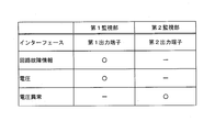
- FIG. 3 is a chart showing information acquired by the first monitoring unit 20 and the second monitoring unit 30 from the voltage detection unit 10.
- the first monitoring unit 20 acquires the voltage detected by the voltage detection unit 10 and the circuit failure information of the voltage detection unit 10 through communication with the voltage detection unit 10.
- the first monitoring unit 20 is constituted by a microcomputer, and functions by executing a program stored in a built-in storage circuit, and performs processing by software.
- the first monitoring unit 20 determines and monitors whether or not the voltage detected by the voltage detection unit 10 is in the normal range.
- the first monitoring unit 20 monitors the presence or absence of a circuit failure in the circuit system on the first output terminal 16 side and the circuit system on the second output terminal 17 side.
- the first monitoring unit 20 identifies a circuit failure at any location in the circuit system configured by the voltage detection circuit 11 and the communication circuit 13 based on circuit failure information acquired from the first output terminal 16, The presence or absence of a circuit failure in the circuit on the output terminal 16 side is determined.
- the first monitoring unit 20 is identified by circuit failure information obtained from the first output terminal 16 in any part of the circuit system constituted by the voltage detection circuit 11, the abnormality detection circuit 12, and the terminal output circuit 14. Then, the presence or absence of a circuit failure in the circuit on the second output terminal 17 side is determined.
- the first monitoring unit 20 notifies the traveling control unit 70 of the voltage abnormality and the presence or absence of a circuit failure as a monitoring result.
- the second monitoring unit 30 acquires a voltage abnormality signal output from the abnormality detection circuit 12 from the second output terminal 17 of the voltage detection unit 10.
- the second monitoring unit 30 acquires voltage abnormality signals from the plurality of voltage detection units 10, takes a logical sum by a logical sum operation circuit, and receives a voltage abnormality signal (abnormality) from one of the voltage detection units 10. In this case, an error signal is output.
- the second monitoring unit 30 is configured by connection lines and discrete individual components, and performs processing by hardware that does not involve program processing.
- the second monitoring unit 30 notifies the traveling control unit 70 of the presence or absence of voltage abnormality as a monitoring result.
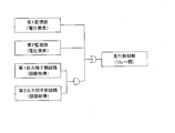
- FIG. 4 is a schematic diagram for explaining a logical operation of relay opening / closing in the traveling control unit 70.
- the traveling control unit 70 determines whether there is a voltage abnormality in the power storage unit 6 notified from the first monitoring unit 20 and the second monitoring unit 30, and a circuit failure in the circuits on the first output terminal 16 side and the second output terminal 17 side. Is input, and relay 71 is opened to disconnect power storage unit 6 and traveling motor 8 from each other. Traveling control unit 70 calculates the voltage abnormality of power storage unit 6 notified from first monitoring unit 20 and second monitoring unit 30 by a logical sum, and controls relay 71 to an open state. In other words, when either one or both of the first monitoring unit 20 and the second monitoring unit 30 notify that there is a voltage abnormality in the power storage unit 6, the traveling control unit 70 controls the relay 71 to be in an open state.
- the traveling control unit 70 calculates a circuit failure in the circuit on the first output terminal 16 side and the second output terminal 17 side notified from the first monitoring unit 20 by logical product, and uses it as an input to the above logical sum.
- the relay 71 is controlled to be open. That is, when both of the circuits on the first output terminal 16 side and the second output terminal 17 side have a circuit failure, the traveling control unit 70 controls the relay 71 to the open state. When only one of the circuits on the first output terminal 16 side and the second output terminal 17 side has a circuit failure, the travel control unit 70 keeps the relay 71 closed, and the power storage unit 6 and the travel motor 8 Is connected. Thereby, the monitoring system 100 can improve the running continuity of the vehicle while suppressing an increase in the circuit scale for monitoring the power storage unit 6.
- the first monitoring unit 20 acquires information (voltage and circuit failure information) output from the communication circuit 13 of the voltage detection unit 10 via the first output terminal 16.
- the second monitoring unit 30 acquires information (abnormal voltage signal) output from the terminal output circuit 14 of the voltage detection unit 10 to the second output terminal 17.
- the traveling control unit 70 acquires from the first monitoring unit 20 whether there is a circuit failure in the circuits on the first output terminal 16 side and the second output terminal 17 side.
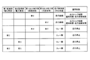
- FIG. 5 is a chart showing treatment details of the travel control unit 70 corresponding to the monitoring situation.
- the travel control unit 70 keeps the relay 71 closed when only one of the circuits on the first output terminal 16 side and the second output terminal 17 side has a circuit failure. Limit.
- the monitoring system 100 increases the running continuity of the vehicle, although the operation is restricted when only one of the circuits on the first output terminal 16 side and the second output terminal 17 side has a circuit failure. Can do.
- the traveling control unit 70 limits the output torque of the traveling motor 8 in order to suppress the discharge of the power storage unit 6.
- the traveling control unit 70 may limit the operation time or the traveling distance of the traveling motor 8.
- the traveling control unit 70 opens the relay 71 and stops the operation of the traveling motor 8 when both of the circuits on the first output terminal 16 side and the second output terminal 17 side have a circuit failure.
- the traveling control unit 70 opens the relay 71 and stops the operation of the traveling motor 8. To do.
- the travel control unit 70 has less operational restrictions when the circuit on the first output terminal 16 side has no circuit failure and the circuit on the second output terminal 17 side has a circuit failure than in the opposite case. You may do it. Since the first monitoring unit 20 is configured by a microcomputer as described above, when there is a circuit failure in the circuit on the second output terminal 17 side, the first monitoring unit 20 is flexible, for example, by increasing the monitoring accuracy by a processing program that deals with the circuit failure. Have sex. Note that the operational restriction is gradual because, for example, the output torque of the traveling motor 8 can be set higher and the operation time or traveling distance of the traveling motor 8 can be set longer than when the operational restriction is severe. is there. Thereby, the monitoring system 100 can change the operation restriction of the traveling motor 8 according to the monitoring situation, and can further improve the traveling continuity of the vehicle.
- the abnormality detection circuit 12 of the voltage detection unit 10 acquires the voltage of the power storage unit 6 from the voltage detection circuit 11 and detects the voltage abnormality.
- the abnormality detection circuit 12 is configured to detect the voltage abnormality. It is good also as a structure which detects the voltage abnormality by detecting the voltage of the electrical storage part 6 by another system. Thereby, the independence of the 1st monitoring part 20 and the 2nd monitoring part 30 can be increased.
- the second monitoring unit 30 notifies the travel control unit 70 of the voltage abnormality, but can also determine and notify a circuit failure by itself.
- the second monitoring unit 30 acquires the voltage of the power storage unit 6 and the voltage abnormality signal from the voltage detection unit 10.
- FIG. 6 is a chart showing an example of determination of a circuit failure based on the voltage and voltage abnormality in the modification.
- the second monitoring unit 30 indicates that the voltage abnormality signal acquired from the voltage detection unit 10 indicates no abnormality, and the voltage of the power storage unit 6 acquired from the voltage detection unit 10 is normal. If it is within the range, it is determined to be normal. As in case # 2 shown in the chart of FIG. 6, the second monitoring unit 30 indicates that the voltage abnormality signal acquired from the voltage detection unit 10 indicates no abnormality, and the voltage of the power storage unit 6 acquired from the voltage detection unit 10 is normal. If it is out of range, it is determined that a circuit failure has occurred.
- the second monitoring unit 30 indicates that the voltage abnormality signal acquired from the voltage detection unit 10 is abnormal, and the voltage of the power storage unit 6 acquired from the voltage detection unit 10 is If it is within the normal range, it is determined that a circuit failure has occurred.
- the second monitoring unit 30 indicates that the voltage abnormality signal acquired from the voltage detection unit 10 is abnormal, and the voltage of the power storage unit 6 acquired from the voltage detection unit 10 is normal. If it is out of range, it is determined that the voltage is abnormal.
- Such determination in the second monitoring unit 30 uses a circuit configured by discrete individual components such as an AD converter that converts an analog signal into a digital signal and a comparison operation unit, and is performed by hardware that does not involve processing by a program. Can be processed.
- the second monitoring unit 30 notifies the traveling control unit 70 of the determined circuit failure as a circuit failure of the second output terminal 17 side circuit.
- the traveling control unit 70 may incorporate the presence / absence of a circuit failure in the circuit on the second output terminal 17 notified from the second monitoring unit 30 in the determination for restricting the operation of the traveling motor 8.
- a first output terminal (16) for detecting the voltage of the power storage unit (6) mounted on the vehicle and outputting the detected voltage together with its own circuit failure information, and a voltage indicating whether or not the detected voltage is abnormal A voltage detector (10) having a second output terminal (17) for outputting an abnormal signal;
- the travel control unit (70) If there is a circuit failure in both the circuit on the first output terminal (16) side and the circuit on the second output terminal (17) side, the travel control unit (70) If the traveling motor (8) is disconnected, there is a circuit failure on one side, no circuit failure on the other, and the power storage unit (6) is normal, the power storage unit (6) and A monitoring system (100), wherein the traveling motor (8) is connected. As a result, the monitoring system (100) can improve the vehicle continuity when only one of the circuit on the first output terminal (16) side and the circuit on the second output terminal (17) side has a circuit failure. Can be increased.
- the traveling control unit (70) has a circuit failure in one of the circuit on the first output terminal (16) side and the circuit on the second output terminal (17) side, and there is no circuit failure on the other side.
- the monitoring system (100) according to item 1, wherein operation of the motor (8) for travel is limited. Thereby, although the monitoring system (100) restrict
- the travel control unit (70) includes the first output than when the circuit on the first output terminal (16) side has a circuit failure and the circuit on the second output terminal (17) side has no circuit failure.
- the monitoring system (100) according to item 2, characterized in that According to this, the monitoring system (100) can change the operation restriction of the traveling motor (8) according to the monitoring situation, and can further improve the vehicle continuity.
- 10 voltage detection unit 16 first output terminal, 17 second output terminal, 20 first monitoring unit, 30 second monitoring unit, 6 power storage unit, 70 traveling control unit, 8 traveling motor, 100 monitoring system.
Landscapes
- Engineering & Computer Science (AREA)
- Power Engineering (AREA)
- Transportation (AREA)
- Mechanical Engineering (AREA)
- Life Sciences & Earth Sciences (AREA)
- Sustainable Development (AREA)
- Sustainable Energy (AREA)
- Physics & Mathematics (AREA)
- General Physics & Mathematics (AREA)
- Electric Propulsion And Braking For Vehicles (AREA)
- Tests Of Electric Status Of Batteries (AREA)
Abstract
蓄電部を監視する回路規模の増大を抑制しつつ、車両の走行継続性を高めることができる監視システムを提供するために、監視システム(100)は、電圧検出部(10)が検出した電圧、および回路故障情報を第1出力端子から取得する第1監視部(20)と、電圧検出部(10)が検出した電圧異常信号を第2出力端子から取得する第2監視部(30)と、蓄電部(6)および走行用モータ(8)の電気的接続を遮断する走行制御部(70)と、を備える。走行制御部(70)は、第1出力端子側の回路および第2出力端子側の回路の一方に回路故障が有り、他方に回路故障が無く、かつ、蓄電部(6)が正常である場合には、蓄電部(6)および走行用モータ(8)を接続状態とする。
Description
本発明は、車両に搭載された蓄電部を監視する監視システムに関する。
特許文献1には、蓄電セルの電圧を検出する主検出回路および副検出回路、蓄電セルを主検出回路に接続する主検出線、並びに、蓄電セルを副検出回路に接続する副検出線を備える監視装置が開示されている。この監視装置において、主検出線と副検出線は少なくとも一部が電気的に独立するように別配線で構成されている。また、監視装置において、主検出回路は主マイコンによって制御されており、副検出回路は副マイコンによって制御されている。主マイコンは主検出線の断線の有無を判定し、副マイコンは副検出線の断線の有無を判定する。
特許文献1に記載の監視装置は、主マイコン系統と副マイコン系統とが、蓄電セルに接続する検出線を含めて独立した構成となっており、冗長性は増すものの、回路の複雑性も増し、回路規模が大きくなってしまうという問題点があった。
ところで、蓄電セルの電圧検出器に故障が生じた場合であっても、蓄電セル自体は故障しておらず、車両の走行に支障がない場合がある。このような場合には、蓄電セルを十分に監視できていないものの、走行用モータの運用を制限しつつ、車両の走行継続性を高めることが望まれていた。
本発明は、斯かる事情に鑑みてなされたものであり、その目的とするところは、蓄電部を監視する回路規模の増大を抑制しつつ、車両の走行継続性を高めることができる監視システムを提供することにある。
本発明のある態様の監視システムは、車両に搭載された蓄電部の電圧を検出し、検出した電圧を自己の回路故障情報とともに出力する第1出力端子、および検出した電圧が異常であるか否かを示す電圧異常信号を出力する第2出力端子を有する電圧検出部と、第1出力端子に接続されており、第1出力端子から出力される電圧および回路故障情報を取得する第1監視部と、第2出力端子に接続されており、第2出力端子から出力される電圧異常信号を取得する第2監視部と、第1監視部および第2監視部からの通知に基いて、蓄電部および走行用モータの電気的接続を遮断する走行制御部と、を備え、走行制御部は、第1出力端子側の回路および第2出力端子側の回路の双方に回路故障が有る場合には、蓄電部および走行用モータの接続を遮断し、一方に回路故障が有り、他方に回路故障が無く、かつ、蓄電部が正常である場合には、蓄電部および前記走行用モータを接続状態とする。
本発明によれば、蓄電部を監視する回路規模の増大を抑制しつつ、車両の走行継続性を高めることができる。
以下、本発明を好適な実施の形態をもとに図1から図6を参照しながら説明する。各図面に示される同一または同等の構成要素、部材には、同一の符号を付するものとし、適宜重複した説明は省略する。また、各図面における部材の寸法は、理解を容易にするために適宜拡大、縮小して示される。また、各図面において実施の形態を説明する上で重要ではない部材の一部は省略して表示する。
(実施形態)
図1は、実施形態に係る監視システム100の構成を示すブロック図である。監視システム100は、監視部1、走行制御部70およびリレー71を備える。走行制御部70は、監視部1から入力される信号に基づいて、リレー71を制御する。また、走行制御部70は、車両に搭載された蓄電部6の状態を監視し、蓄電部6による走行用モータ8の駆動を制御する。蓄電部6は、複数の蓄電セル61(図2参照)、例えばリチウムイオン電池セルが直列接続されて形成される。尚、蓄電セル61は、リチウムイオン電池セルのほか、ニッケル水素電池セル、鉛電池セル、電気二重層キャパシタセル、リチウムイオンキャパシタセル等であってもよい。
図1は、実施形態に係る監視システム100の構成を示すブロック図である。監視システム100は、監視部1、走行制御部70およびリレー71を備える。走行制御部70は、監視部1から入力される信号に基づいて、リレー71を制御する。また、走行制御部70は、車両に搭載された蓄電部6の状態を監視し、蓄電部6による走行用モータ8の駆動を制御する。蓄電部6は、複数の蓄電セル61(図2参照)、例えばリチウムイオン電池セルが直列接続されて形成される。尚、蓄電セル61は、リチウムイオン電池セルのほか、ニッケル水素電池セル、鉛電池セル、電気二重層キャパシタセル、リチウムイオンキャパシタセル等であってもよい。
監視部1は、複数の電圧検出部10、第1監視部20、および第2監視部30を有する。電圧検出部10は、蓄電部6の電圧を検出するとともに、過充電または過放電による異常の有無を検出し、第1監視部20および第2監視部30へ出力する。第1監視部20は、蓄電部6の異常の有無、電圧検出部10における回路故障の有無を走行制御部70へ通知し、第2監視部30は蓄電部6の異常の有無を走行制御部70へ通知する。走行制御部70は、第1監視部20および第2監視部30の通知に基づいて、リレー71を開閉して蓄電部6および走行用モータ8の電気的接続/遮断を制御し、走行用モータ8を駆動する。
図2は、電圧検出部10の構成を示すブロック図である。電圧検出部10は、蓄電部6の電圧を検出する電圧検出回路11、異常検出回路12、通信回路13、端子出力回路14および回路故障検出部15を有し、例えばASIC(Application Specific Integrated Circuit)で構成されている。電圧検出回路11は、複数の蓄電セル61を直列に接続してなる蓄電部6の電圧を、蓄電セル61単位で検出、または隣接する2以上の蓄電セル61をブロックとして、該ブロック単位で検出する。
異常検出回路12は、電圧検出回路11で検出した電圧を所定の閾値と比較し、過充電または過放電による異常の有無を検出する。異常検出回路12は、検出する電圧が正常範囲の上限側である過充電閾値より高い場合に過充電による異常であることを検出する。異常検出回路12は、検出する電圧が正常範囲の下限側である過放電閾値より低い場合に過放電による異常であることを検出する。異常検出回路12は、電圧異常信号として、正常な場合にハイレベルを、過充電または過放電が検出された場合にローレベルを出力する。
通信回路13は、電圧検出回路11によって検出した電圧、および回路故障検出部15が検出する回路故障情報を第1出力端子16に接続される第1監視部20へ送信する。通信回路13は、例えば、アイソレータを介して第1監視部20と絶縁接続され、シリアル通信によって情報を第1監視部20へ送信する。尚、通信回路13は、例えばSPI(Serial Peripheral Interface)通信方式等に基いて外部と通信するための回路である。
端子出力回路14は、異常検出回路12からの電圧異常信号を第2出力端子17へ出力する。第2出力端子17は、電圧異常信号として、正常な場合にハイレベル(5V)を、過充電または過放電が検出された場合にローレベル(0V)を出力する。第2監視部30は、第2出力端子17に接続されており、第2出力端子17から異常検出回路12が出力する電圧異常信号を取得する。
回路故障検出部15は、電圧検出部10における各回路の故障を検出している。回路故障検出部15は、電圧検出回路11における、蓄電部6との間の接続線の断線故障、電圧検出回路11の電圧測定精度のエラー、異常検出回路12における、閾値との比較回路のエラー等の回路故障を検出する。また、回路故障検出部15は、通信回路13における通信エラー、端子出力回路14における端子出力エラー等の回路故障を検出する。回路故障検出部15によって検出される回路故障情報は、通信回路13から第1監視部20へ送信される。
図3は電圧検出部10から第1監視部20および第2監視部30が取得する情報を示す図表である。第1監視部20は、電圧検出部10との通信によって、電圧検出部10が検出した電圧、および電圧検出部10の回路故障情報を取得する。第1監視部20は、マイコンで構成されており、内蔵する記憶回路に記憶したプログラムを実行することによって機能し、ソフトウェアによる処理を行う。第1監視部20は、電圧検出部10が検出した電圧が正常範囲にあるか否かを自ら判定して監視する。第1監視部20は、第1出力端子16側の回路系、および第2出力端子17側の回路系における回路故障の有無を監視している。第1監視部20は、電圧検出回路11および通信回路13で構成される回路系のいずれかの箇所での回路故障を第1出力端子16から取得する回路故障情報に基いて特定し、第1出力端子16側の回路における回路故障の有無を判定する。第1監視部20は、電圧検出回路11、異常検出回路12および端子出力回路14で構成される回路系のいずれかの箇所での回路故障を第1出力端子16から取得する回路故障情報によって特定し、第2出力端子17側の回路における回路故障の有無を判定する。第1監視部20は、監視結果として、電圧異常、および回路故障の有無を走行制御部70へ通知する。
第2監視部30は、電圧検出部10の第2出力端子17から異常検出回路12が出力する電圧異常信号を取得する。第2監視部30は、複数の電圧検出部10から電圧異常信号を取得し、論理和演算回路によって論理和を取り、いずれかの電圧検出部10から電圧異常信号(異常有り)が入力された場合に異常有りとの信号を出力する。第2監視部30は、接続線とディスクリートな個別部品によって構成されており、プログラム処理を伴わないハードウェアによる処理を行う。第2監視部30は、監視結果として、電圧異常の有無を走行制御部70へ通知する。
次に監視システムの動作について説明する。
図4は、走行制御部70におけるリレー開閉の論理演算を説明するための模式図である。走行制御部70は、第1監視部20および第2監視部30から通知された蓄電部6の電圧異常の有無、並びに、第1出力端子16側および第2出力端子17側の回路における回路故障の有無を入力とし、リレー71を開状態にして蓄電部6および走行用モータ8の接続を遮断する。走行制御部70は、第1監視部20および第2監視部30から通知される蓄電部6の電圧異常を論理和によって演算し、リレー71を開状態に制御する。即ち、第1監視部20および第2監視部30のうちいずれか一方、または双方が蓄電部6の電圧異常有りを通知した場合に、走行制御部70はリレー71を開状態に制御する。
図4は、走行制御部70におけるリレー開閉の論理演算を説明するための模式図である。走行制御部70は、第1監視部20および第2監視部30から通知された蓄電部6の電圧異常の有無、並びに、第1出力端子16側および第2出力端子17側の回路における回路故障の有無を入力とし、リレー71を開状態にして蓄電部6および走行用モータ8の接続を遮断する。走行制御部70は、第1監視部20および第2監視部30から通知される蓄電部6の電圧異常を論理和によって演算し、リレー71を開状態に制御する。即ち、第1監視部20および第2監視部30のうちいずれか一方、または双方が蓄電部6の電圧異常有りを通知した場合に、走行制御部70はリレー71を開状態に制御する。
また、走行制御部70は、第1監視部20から通知される第1出力端子16側および第2出力端子17側の回路における回路故障を論理積によって演算し、上述の論理和への入力とし、リレー71を開状態に制御する。即ち、第1出力端子16側および第2出力端子17側の回路の双方に回路故障が有る場合に、走行制御部70はリレー71を開状態に制御する。第1出力端子16側および第2出力端子17側の回路のいずれか一方のみに回路故障が有る場合には、走行制御部70はリレー71を閉状態に保ち、蓄電部6および走行用モータ8を接続状態とする。これにより、監視システム100は、蓄電部6を監視する回路規模の増大を抑制しつつ、車両の走行継続性を高めることができる。
第1監視部20は、電圧検出部10の通信回路13から第1出力端子16を介して出力される各情報(電圧および回路故障情報)を取得している。一方、第2監視部30は、電圧検出部10の端子出力回路14から第2出力端子17に出力される情報(異常電圧信号)を取得している。走行制御部70は、第1出力端子16側および第2出力端子17側の回路における回路故障の有無を第1監視部20から取得する。
図5は、監視状況に対応する走行制御部70の処置内容を示す図表である。走行制御部70は、第1出力端子16側および第2出力端子17側の回路のいずれか一方のみに回路故障が有る場合には、リレー71を閉状態に保つが、走行用モータ8の運用を制限する。
これにより、監視システム100は、第1出力端子16側および第2出力端子17側の回路のいずれか一方のみに回路故障が有る場合に、運用制限がかかるものの、車両の走行継続性を高めることができる。
これにより、監視システム100は、第1出力端子16側および第2出力端子17側の回路のいずれか一方のみに回路故障が有る場合に、運用制限がかかるものの、車両の走行継続性を高めることができる。
図5に示す例では、走行制御部70は、蓄電部6の放電を抑制するために走行用モータ8の出力トルクを制限する。また、走行制御部70は、走行用モータ8の運用時間または走行距離を制限することも考えられる。尚、走行制御部70は、第1出力端子16側および第2出力端子17側の回路の双方に回路故障が有る場合には、リレー71を開状態とし、走行用モータ8の運用を停止する。また、走行制御部70は、第1監視部20および第2監視部30のいずれか一方、または双方が電圧異常有りを通知した場合、リレー71を開状態とし、走行用モータ8の運用を停止する。
走行制御部70は、第1出力端子16側の回路に回路故障が無く、第2出力端子17側の回路に回路故障が有る場合に、その逆の場合に比べて、運用制限が緩やかであるようにしてもよい。第1監視部20は、上述のようにマイコンで構成されているため、第2出力端子17側の回路に回路故障が有る場合に、回路故障に対処した処理プログラム等によって監視精度を高めるなど柔軟性を持つ。尚、運用制限が緩やかであるとは、運用制限が厳しい場合に比較して、例えば走行用モータ8の出力トルクを高めに設定でき、走行用モータ8の運用時間または走行距離を長く設定できることである。これにより、監視システム100は、走行用モータ8の運用制限を監視状況に合わせて変更し、より車両の走行継続性を高めることができる。
(変形例)
上述の実施形態では、電圧検出部10の異常検出回路12が電圧検出回路11から蓄電部6の電圧を取得して電圧異常を検出する構成としたが、異常検出回路12が、電圧検出回路11とは別系統で蓄電部6の電圧を検出して電圧異常を検出する構成としても良い。
これにより、第1監視部20および第2監視部30の独立性を増すことができる。
上述の実施形態では、電圧検出部10の異常検出回路12が電圧検出回路11から蓄電部6の電圧を取得して電圧異常を検出する構成としたが、異常検出回路12が、電圧検出回路11とは別系統で蓄電部6の電圧を検出して電圧異常を検出する構成としても良い。
これにより、第1監視部20および第2監視部30の独立性を増すことができる。
また、第2監視部30は、電圧異常を走行制御部70へ通知しているが、回路故障を自ら判断して通知することもできる。例えば、第2監視部30は、電圧検出部10から蓄電部6の電圧と電圧異常信号を取得するようにする。図6は、変形例における電圧および電圧異常に基づく回路故障の判断例を示す図表である。
第2監視部30は、図6の図表に示すケース#1のように、電圧検出部10から取得した電圧異常信号が異常なしを示し、電圧検出部10から取得した蓄電部6の電圧が正常範囲内である場合には正常であると判断する。第2監視部30は、図6の図表に示すケース#2のように、電圧検出部10から取得した電圧異常信号が異常なしを示し、電圧検出部10から取得した蓄電部6の電圧が正常範囲外である場合には回路故障であると判断する。
また第2監視部30は、図6の図表に示すケース#3のように、電圧検出部10から取得した電圧異常信号が異常ありを示し、電圧検出部10から取得した蓄電部6の電圧が正常範囲内である場合には回路故障であると判断する。第2監視部30は、図6の図表に示すケース#4のように、電圧検出部10から取得した電圧異常信号が異常ありを示し、電圧検出部10から取得した蓄電部6の電圧が正常範囲外である場合には電圧異常であると判断する。このような第2監視部30における判断は、アナログ信号をデジタル信号に変換するAD変換器、および比較演算器等のディスクリートな個別部品によって構成した回路を用い、プログラムによる処理を伴わないハードウェアによって処理することができる。
第2監視部30は、判断した回路故障の有無を第2出力端子17側回路の回路故障として走行制御部70へ通知する。走行制御部70は、第2監視部30から通知される第2出力端子17側回路の回路故障の有無を、走行用モータ8の運用制限のための判断に取り入れてもよい。
以上、本発明の実施の形態をもとに説明した。これらの実施の形態は例示であり、いろいろな変形および変更が本発明の特許請求範囲内で可能なこと、またそうした変形例および変更も本発明の特許請求の範囲にあることは当業者に理解されるところである。従って、本明細書での記述および図面は限定的ではなく例証的に扱われるべきものである。
尚、実施形態は以下の項目によって特定されてもよい。
[項目1]
車両に搭載された蓄電部(6)の電圧を検出し、検出した電圧を自己の回路故障情報とともに出力する第1出力端子(16)、および検出した電圧が異常であるか否かを示す電圧異常信号を出力する第2出力端子(17)を有する電圧検出部(10)と、
前記第1出力端子(16)に接続されており、前記第1出力端子(16)から出力される電圧および回路故障情報を取得する第1監視部(20)と、
前記第2出力端子(17)に接続されており、前記第2出力端子(17)から出力される電圧異常信号を取得する第2監視部(30)と、
前記第1監視部(20)および前記第2監視部(30)からの通知に基いて、前記蓄電部(6)および走行用モータ(8)の電気的接続を遮断する走行制御部(70)と、を備え、
前記走行制御部(70)は、前記第1出力端子(16)側の回路および前記第2出力端子(17)側の回路の双方に回路故障が有る場合には、前記蓄電部(6)および前記走行用モータ(8)の接続を遮断し、一方に回路故障が有り、他方に回路故障が無く、かつ、前記蓄電部(6)が正常である場合には、前記蓄電部(6)および前記走行用モータ(8)を接続状態とすることを特徴とする監視システム(100)。これにより、監視システム(100)は、第1出力端子(16)側の回路および第2出力端子(17)側の回路のいずれか一方のみに回路故障が有る場合に、車両の走行継続性を高めることができる。
[項目2]
前記走行制御部(70)は、前記第1出力端子(16)側の回路および前記第2出力端子(17)側の回路のうち一方に回路故障が有り、他方に回路故障が無い場合に、前記走行用モータ(8)の運用を制限することを特徴とする項目1に記載の監視システム(100)。これにより、監視システム(100)は、走行用モータ(8)の運用を制限するものの、車両の走行継続性を高めることができる。
[項目3]
前記走行制御部(70)は、前記第1出力端子(16)側の回路に回路故障が有り、前記第2出力端子(17)側の回路に回路故障が無い場合よりも、前記第1出力端子(16)側の回路に回路故障が無く、前記第2出力端子(17)側の回路に回路故障が有る場合の方が、前記走行用モータ(8)の運用制限が緩やかであることを特徴とする項目2に記載の監視システム(100)。これによれば、監視システム(100)は、走行用モータ(8)の運用制限を監視状況に合わせて変更し、より車両の走行継続性を高めることができる。
10 電圧検出部、 16 第1出力端子、 17 第2出力端子、 20 第1監視部、 30 第2監視部、 6 蓄電部、 70 走行制御部、 8 走行用モータ、 100 監視システム。
Claims (3)
- 車両に搭載された蓄電部の電圧を検出し、検出した電圧を自己の回路故障情報とともに出力する第1出力端子、および検出した電圧が異常であるか否かを示す電圧異常信号を出力する第2出力端子を有する電圧検出部と、
前記第1出力端子に接続されており、前記第1出力端子から出力される電圧および回路故障情報を取得する第1監視部と、
前記第2出力端子に接続されており、前記第2出力端子から出力される電圧異常信号を取得する第2監視部と、
前記第1監視部および前記第2監視部からの通知に基いて、前記蓄電部および走行用モータの電気的接続を遮断する走行制御部と、を備え、
前記走行制御部は、前記第1出力端子側の回路および前記第2出力端子側の回路の双方に回路故障が有る場合には、前記蓄電部および前記走行用モータの接続を遮断し、一方に回路故障が有り、他方に回路故障が無く、かつ、前記蓄電部が正常である場合には、前記蓄電部および前記走行用モータを接続状態とすることを特徴とする監視システム。 - 前記走行制御部は、前記第1出力端子側の回路および前記第2出力端子側の回路のうち一方に回路故障が有り、他方に回路故障が無い場合に、前記走行用モータの運用を制限することを特徴とする請求項1に記載の監視システム。
- 前記走行制御部は、前記第1出力端子側の回路に回路故障が有り、前記第2出力端子側の回路に回路故障が無い場合よりも、前記第1出力端子側の回路に回路故障が無く、前記第2出力端子側の回路に回路故障が有る場合の方が、前記走行用モータの運用制限が緩やかであることを特徴とする請求項2に記載の監視システム。
Priority Applications (3)
| Application Number | Priority Date | Filing Date | Title |
|---|---|---|---|
| JP2019512409A JP7077307B2 (ja) | 2017-04-11 | 2018-03-26 | 監視システム |
| CN201880024754.7A CN110520324B (zh) | 2017-04-11 | 2018-03-26 | 监视系统 |
| US16/500,975 US10843567B2 (en) | 2017-04-11 | 2018-03-26 | Monitoring system |
Applications Claiming Priority (2)
| Application Number | Priority Date | Filing Date | Title |
|---|---|---|---|
| JP2017-078316 | 2017-04-11 | ||
| JP2017078316 | 2017-04-11 |
Publications (1)
| Publication Number | Publication Date |
|---|---|
| WO2018190107A1 true WO2018190107A1 (ja) | 2018-10-18 |
Family
ID=63792597
Family Applications (1)
| Application Number | Title | Priority Date | Filing Date |
|---|---|---|---|
| PCT/JP2018/011968 Ceased WO2018190107A1 (ja) | 2017-04-11 | 2018-03-26 | 監視システム |
Country Status (4)
| Country | Link |
|---|---|
| US (1) | US10843567B2 (ja) |
| JP (1) | JP7077307B2 (ja) |
| CN (1) | CN110520324B (ja) |
| WO (1) | WO2018190107A1 (ja) |
Cited By (1)
| Publication number | Priority date | Publication date | Assignee | Title |
|---|---|---|---|---|
| JP2024000279A (ja) * | 2022-06-20 | 2024-01-05 | 株式会社クボタ | 電動作業車 |
Families Citing this family (1)
| Publication number | Priority date | Publication date | Assignee | Title |
|---|---|---|---|---|
| WO2022176622A1 (ja) * | 2021-02-22 | 2022-08-25 | パナソニックIpマネジメント株式会社 | 故障予測システム、故障予測方法、および故障予測プログラム |
Citations (2)
| Publication number | Priority date | Publication date | Assignee | Title |
|---|---|---|---|---|
| JP2011234506A (ja) * | 2010-04-27 | 2011-11-17 | Hitachi Vehicle Energy Ltd | 組電池の制御装置 |
| JP2014048281A (ja) * | 2012-09-04 | 2014-03-17 | Sanyo Electric Co Ltd | 電源装置および故障検出回路 |
Family Cites Families (12)
| Publication number | Priority date | Publication date | Assignee | Title |
|---|---|---|---|---|
| DE2903219A1 (de) * | 1979-01-27 | 1980-08-07 | Bosch Gmbh Robert | Vorrichtung zur anzeige von reglerausfaellen bei lichtmaschinen |
| EP1024985B1 (de) * | 1997-10-24 | 2003-01-15 | Continental Teves AG & Co. oHG | Schaltungsanordnung zur spannungsüberwachung einer geregelten ausgangsspannung in einem kraftfahrzeug |
| DE10355206A1 (de) * | 2003-11-26 | 2005-07-07 | Hella Kgaa Hueck & Co. | Schaltungsanordnung für Kraftfahrzeuge zur Überwachung von in Reihe geschalteten Batterien |
| US20060043933A1 (en) * | 2004-08-31 | 2006-03-02 | Latinis Gary R | Battery voltage monitor |
| US7982593B2 (en) * | 2008-10-01 | 2011-07-19 | Lifetech Energy Inc. | Alarm device of vehicle battery for monitoring voltage ranges in charging and discharging processes of vehicle battery |
| US20130063154A1 (en) * | 2010-05-28 | 2013-03-14 | Sanyo Electric Co., Ltd. | Power supply apparatus |
| AU2011346099B2 (en) * | 2010-12-22 | 2014-12-18 | Kyushu Electric Power Co., Inc. | Power supply device |
| DE102011089556A1 (de) * | 2011-12-22 | 2013-06-27 | Robert Bosch Gmbh | Vorrichtung und Verfahren zur Überwachung einer Spannungsversorgung für ein Fahrzeugsystem |
| US9341665B2 (en) * | 2012-04-18 | 2016-05-17 | Lear Corporation | Method and apparatus for high voltage isolation monitor for a vehicle |
| JP6002025B2 (ja) * | 2012-12-20 | 2016-10-05 | 株式会社ユーシン | 電動ステアリングロック装置 |
| JP6056553B2 (ja) | 2013-03-01 | 2017-01-11 | 株式会社デンソー | 電池監視装置 |
| US9140759B2 (en) * | 2013-11-12 | 2015-09-22 | Ford Global Technologies, Llc | Electric vehicle battery pack voltage monitoring |
-
2018
- 2018-03-26 US US16/500,975 patent/US10843567B2/en active Active
- 2018-03-26 WO PCT/JP2018/011968 patent/WO2018190107A1/ja not_active Ceased
- 2018-03-26 CN CN201880024754.7A patent/CN110520324B/zh active Active
- 2018-03-26 JP JP2019512409A patent/JP7077307B2/ja active Active
Patent Citations (2)
| Publication number | Priority date | Publication date | Assignee | Title |
|---|---|---|---|---|
| JP2011234506A (ja) * | 2010-04-27 | 2011-11-17 | Hitachi Vehicle Energy Ltd | 組電池の制御装置 |
| JP2014048281A (ja) * | 2012-09-04 | 2014-03-17 | Sanyo Electric Co Ltd | 電源装置および故障検出回路 |
Cited By (2)
| Publication number | Priority date | Publication date | Assignee | Title |
|---|---|---|---|---|
| JP2024000279A (ja) * | 2022-06-20 | 2024-01-05 | 株式会社クボタ | 電動作業車 |
| JP7788949B2 (ja) | 2022-06-20 | 2025-12-19 | 株式会社クボタ | 電動作業車 |
Also Published As
| Publication number | Publication date |
|---|---|
| JP7077307B2 (ja) | 2022-05-30 |
| CN110520324A (zh) | 2019-11-29 |
| JPWO2018190107A1 (ja) | 2020-02-27 |
| US20200033418A1 (en) | 2020-01-30 |
| US10843567B2 (en) | 2020-11-24 |
| CN110520324B (zh) | 2022-11-29 |
Similar Documents
| Publication | Publication Date | Title |
|---|---|---|
| US9647301B2 (en) | Battery monitoring apparatus | |
| JP4196122B2 (ja) | 電池パック | |
| JP5745694B2 (ja) | 自己故障診断機能を備える絶縁抵抗測定装置及びそれを用いた自己故障診断方法 | |
| US9091737B2 (en) | Architecture of a battery and control device | |
| US9840157B2 (en) | Battery management system and battery system | |
| US9400312B2 (en) | Battery system and method for determining battery module voltages | |
| JP6361808B2 (ja) | バッテリーパック | |
| JP2012122856A (ja) | 組電池装置 | |
| JP2013206643A (ja) | 電池システムのリレー溶着検知装置、及びこれを用いた電池システム | |
| KR101473395B1 (ko) | 고장 자가 진단 기능을 구비한 절연 저항 측정 장치 및 이를 이용한 고장 자가 진단 방법 | |
| JP7039563B2 (ja) | 監視装置および蓄電システム | |
| JP2011078165A (ja) | 電圧監視装置 | |
| CN104838522A (zh) | 蓄电池管理系统和蓄电池系统 | |
| JPWO2018101005A1 (ja) | 電池制御装置 | |
| CN102457275B (zh) | 电子控制装置 | |
| JP2013078233A (ja) | 組電池の監視装置、及び該監視装置を備えた電池パック | |
| JP5287682B2 (ja) | 電池監視装置 | |
| JP7077307B2 (ja) | 監視システム | |
| JP6056553B2 (ja) | 電池監視装置 | |
| US9203235B2 (en) | Method for monitoring a disconnection device, in particular a service plug or a service socket, in a battery system, and corresponding monitoring device | |
| JP6129346B2 (ja) | 電池システム監視装置 | |
| JP2011050155A (ja) | 蓄電装置 | |
| KR20190013651A (ko) | 배터리 셀 관리 시스템 | |
| JP6005445B2 (ja) | 電池システム監視装置 | |
| JP2017147077A (ja) | 蓄電装置 |
Legal Events
| Date | Code | Title | Description |
|---|---|---|---|
| 121 | Ep: the epo has been informed by wipo that ep was designated in this application |
Ref document number: 18784604 Country of ref document: EP Kind code of ref document: A1 |
|
| ENP | Entry into the national phase |
Ref document number: 2019512409 Country of ref document: JP Kind code of ref document: A |
|
| NENP | Non-entry into the national phase |
Ref country code: DE |
|
| 122 | Ep: pct application non-entry in european phase |
Ref document number: 18784604 Country of ref document: EP Kind code of ref document: A1 |