WO2018189997A1 - 波長変換部材及び波長変換素子、並びにそれらを用いた発光装置 - Google Patents
波長変換部材及び波長変換素子、並びにそれらを用いた発光装置 Download PDFInfo
- Publication number
- WO2018189997A1 WO2018189997A1 PCT/JP2018/005780 JP2018005780W WO2018189997A1 WO 2018189997 A1 WO2018189997 A1 WO 2018189997A1 JP 2018005780 W JP2018005780 W JP 2018005780W WO 2018189997 A1 WO2018189997 A1 WO 2018189997A1
- Authority
- WO
- WIPO (PCT)
- Prior art keywords
- wavelength conversion
- conversion member
- magnesium oxide
- light
- particles
- Prior art date
- Legal status (The legal status is an assumption and is not a legal conclusion. Google has not performed a legal analysis and makes no representation as to the accuracy of the status listed.)
- Ceased
Links
Images


Classifications
-
- H—ELECTRICITY
- H01—ELECTRIC ELEMENTS
- H01S—DEVICES USING THE PROCESS OF LIGHT AMPLIFICATION BY STIMULATED EMISSION OF RADIATION [LASER] TO AMPLIFY OR GENERATE LIGHT; DEVICES USING STIMULATED EMISSION OF ELECTROMAGNETIC RADIATION IN WAVE RANGES OTHER THAN OPTICAL
- H01S5/00—Semiconductor lasers
- H01S5/02—Structural details or components not essential to laser action
- H01S5/022—Mountings; Housings
- H01S5/0239—Combinations of electrical or optical elements
-
- H—ELECTRICITY
- H10—SEMICONDUCTOR DEVICES; ELECTRIC SOLID-STATE DEVICES NOT OTHERWISE PROVIDED FOR
- H10H—INORGANIC LIGHT-EMITTING SEMICONDUCTOR DEVICES HAVING POTENTIAL BARRIERS
- H10H20/00—Individual inorganic light-emitting semiconductor devices having potential barriers, e.g. light-emitting diodes [LED]
- H10H20/80—Constructional details
- H10H20/85—Packages
- H10H20/851—Wavelength conversion means
- H10H20/8511—Wavelength conversion means characterised by their material, e.g. binder
-
- C—CHEMISTRY; METALLURGY
- C09—DYES; PAINTS; POLISHES; NATURAL RESINS; ADHESIVES; COMPOSITIONS NOT OTHERWISE PROVIDED FOR; APPLICATIONS OF MATERIALS NOT OTHERWISE PROVIDED FOR
- C09K—MATERIALS FOR MISCELLANEOUS APPLICATIONS, NOT PROVIDED FOR ELSEWHERE
- C09K11/00—Luminescent materials, e.g. electroluminescent or chemiluminescent
- C09K11/02—Use of particular materials as binders, particle coatings or suspension media therefor
-
- C—CHEMISTRY; METALLURGY
- C09—DYES; PAINTS; POLISHES; NATURAL RESINS; ADHESIVES; COMPOSITIONS NOT OTHERWISE PROVIDED FOR; APPLICATIONS OF MATERIALS NOT OTHERWISE PROVIDED FOR
- C09K—MATERIALS FOR MISCELLANEOUS APPLICATIONS, NOT PROVIDED FOR ELSEWHERE
- C09K11/00—Luminescent materials, e.g. electroluminescent or chemiluminescent
- C09K11/08—Luminescent materials, e.g. electroluminescent or chemiluminescent containing inorganic luminescent materials
-
- C—CHEMISTRY; METALLURGY
- C09—DYES; PAINTS; POLISHES; NATURAL RESINS; ADHESIVES; COMPOSITIONS NOT OTHERWISE PROVIDED FOR; APPLICATIONS OF MATERIALS NOT OTHERWISE PROVIDED FOR
- C09K—MATERIALS FOR MISCELLANEOUS APPLICATIONS, NOT PROVIDED FOR ELSEWHERE
- C09K11/00—Luminescent materials, e.g. electroluminescent or chemiluminescent
- C09K11/08—Luminescent materials, e.g. electroluminescent or chemiluminescent containing inorganic luminescent materials
- C09K11/64—Luminescent materials, e.g. electroluminescent or chemiluminescent containing inorganic luminescent materials containing aluminium
-
- G—PHYSICS
- G02—OPTICS
- G02B—OPTICAL ELEMENTS, SYSTEMS OR APPARATUS
- G02B5/00—Optical elements other than lenses
- G02B5/20—Filters
-
- H—ELECTRICITY
- H10—SEMICONDUCTOR DEVICES; ELECTRIC SOLID-STATE DEVICES NOT OTHERWISE PROVIDED FOR
- H10H—INORGANIC LIGHT-EMITTING SEMICONDUCTOR DEVICES HAVING POTENTIAL BARRIERS
- H10H20/00—Individual inorganic light-emitting semiconductor devices having potential barriers, e.g. light-emitting diodes [LED]
- H10H20/80—Constructional details
- H10H20/85—Packages
- H10H20/851—Wavelength conversion means
Definitions
- the present invention relates to a wavelength conversion member and a wavelength conversion element for converting the wavelength of light emitted from a light emitting diode (LED: Light Emitting Diode) or a laser diode (LD: Laser Diode), etc., and a light emitting device using them.
- LED Light Emitting Diode
- LD Laser Diode
- next-generation light-emitting device that replaces fluorescent lamps and incandescent lamps
- attention has been focused on light-emitting devices using LEDs and LDs from the viewpoint of low power consumption, small size and light weight, and easy light quantity adjustment.
- a wavelength conversion member that absorbs part of light from the LED and converts it into yellow light is disposed on the LED that emits blue light.
- a light emitting device is disclosed. This light emitting device emits white light that is a combined light of blue light emitted from the LED and yellow light emitted from the wavelength conversion member.
- the wavelength conversion member As the wavelength conversion member, a material in which inorganic phosphor particles are dispersed in a resin matrix is conventionally used. However, when the wavelength conversion member is used, there is a problem that the resin matrix is discolored or deformed by light from the LED. Accordingly, a wavelength conversion member made of a completely inorganic solid in which a phosphor is dispersed and fixed in a glass matrix instead of a resin has been proposed (see, for example, Patent Documents 2 and 3).
- the wavelength conversion member has a feature that a glass matrix as a base material is not easily deteriorated by heat or irradiation light from an LED, and problems such as discoloration and deformation hardly occur.
- the output of LEDs and LDs used as light sources has increased for the purpose of increasing the power of light emitting devices. Accordingly, there is a problem that the temperature of the wavelength conversion member rises due to the heat of the light source or the heat emitted from the phosphor irradiated with the excitation light, and as a result, the emission intensity decreases with time (temperature quenching). In some cases, the temperature rise of the wavelength conversion member becomes significant, and the constituent material (glass matrix or the like) may be dissolved.
- the present invention provides a wavelength conversion member, a wavelength conversion element, and a wavelength conversion member that can suppress a decrease in light emission intensity over time and dissolution of constituent materials when irradiated with high-power LED or LD light, and
- An object is to provide a light emitting device using them.
- the wavelength conversion member of the present invention is a wavelength conversion member containing inorganic phosphor particles and magnesium oxide particles, wherein the magnesium oxide particles are interposed between the inorganic phosphor particles, and the inorganic phosphor particles are It is characterized by being bound by magnesium oxide particles.
- magnesium oxide particles are interposed between the inorganic phosphor particles.
- the magnesium oxide particles are excellent in thermal conductivity as compared with glass or the like, the heat generated in the inorganic phosphor particles can be efficiently released to the outside. As a result, the temperature rise of the wavelength conversion member is suppressed and temperature quenching is less likely to occur.
- Magnesium oxide particles also have excellent heat resistance, so they are difficult to dissolve even when irradiated with light from high-power LEDs and LDs, or suppress the occurrence of problems such as thermal cracks due to rapid temperature rise. There is also an advantage of being able to.
- magnesium oxide particles have an advantage that they can be sintered at a lower temperature than ceramic particles such as aluminum oxide and zirconium oxide. Therefore, the baking temperature at the time of wavelength conversion member preparation can also be made low, and deterioration of the inorganic fluorescent substance powder at the time of baking can be suppressed.
- the wavelength conversion member of the present invention preferably contains 3 to 80% inorganic phosphor particles and 20 to 97% magnesium oxide particles by mass%.
- the average particle diameter of the magnesium oxide particles is preferably 0.01 to 10 ⁇ m. In this way, the denseness of the wavelength conversion member is improved and a heat conduction path is easily formed, so that heat generated in the inorganic phosphor particles can be released to the outside more efficiently.
- the purity of the magnesium oxide particles is preferably 99% or more. In this way, the magnesium oxide particles can be sintered at a relatively low temperature.
- the average particle diameter of the inorganic phosphor particles is preferably 1 to 50 ⁇ m.
- the inorganic phosphor particles are preferably made of an oxide phosphor having a garnet structure. Since the oxide phosphor having a garnet structure is excellent in heat resistance, deterioration of the inorganic phosphor particles per se can be suppressed when irradiated with light from a high-power LED or LD.
- (average particle diameter of magnesium oxide particles) / (average particle diameter of inorganic phosphor particles) is preferably 0.5 or less. In this way, the denseness of the wavelength conversion member is improved and a heat conduction path is easily formed, so that heat generated in the inorganic phosphor particles can be released to the outside more efficiently.
- the wavelength conversion element of the present invention is characterized by comprising a laminate in which the above-described wavelength conversion member and a heat dissipation layer having a higher thermal conductivity than the wavelength conversion member are laminated. If it does in this way, since the heat generated in the wavelength conversion member can be transmitted to the heat dissipation layer, it becomes easy to suppress the temperature rise of the wavelength conversion member.
- a heat radiation layer made of translucent ceramics can be used.
- the translucent ceramic aluminum oxide ceramics, aluminum nitride ceramics, silicon carbide ceramics, boron nitride ceramics, magnesium oxide ceramics, titanium oxide ceramics, niobium oxide ceramics, oxidation At least one selected from zinc-based ceramics and yttrium oxide-based ceramics can be used.
- a light-emitting device of the present invention is characterized by comprising the above-described wavelength conversion member and a light source that irradiates the wavelength conversion member with excitation light.
- the light-emitting device of the present invention is characterized by comprising the above-described wavelength conversion element and a light source that irradiates the wavelength conversion element with excitation light.
- the light source is preferably a laser diode. Since the wavelength conversion member and wavelength conversion element of the present invention are excellent in heat resistance and heat dissipation, it is easy to enjoy the effects of the present invention when a laser diode having a relatively high power is used as the light source.
- a wavelength conversion member and a wavelength conversion element capable of suppressing a decrease in light emission intensity over time and dissolution of constituent materials when irradiated with light of a high-power LED or LD, and the above
- the used light-emitting device can be provided.
- FIG. 1 is a schematic cross-sectional view showing an embodiment of the wavelength conversion member of the present invention.
- the wavelength conversion member 10 contains inorganic phosphor particles 1 and magnesium oxide particles 2.
- the magnesium oxide particles 2 are interposed between the inorganic phosphor particles 1, and the inorganic phosphor particles 1 are bound by the magnesium oxide particles 2.
- the inorganic phosphor particles 1 are not particularly limited as long as they emit fluorescence when incident excitation light is incident.
- Specific examples of the inorganic phosphor particles 1 include, for example, oxide phosphors, nitride phosphors, oxynitride phosphors, chloride phosphors, acid chloride phosphors, sulfide phosphors, and oxysulfide phosphors. , Halide phosphors, chalcogenide phosphors, aluminate phosphors, halophosphate phosphors, and the like. These can be used individually or in mixture of 2 or more types.
- the inorganic phosphor particles 1 are oxide phosphors, particularly oxide phosphors having a garnet structure (Y 3 Al 5 O 12 : Ce 3+ , Lu 3 Al 5 O 12 : Ce 3+ etc.). Preferably there is.
- the average particle diameter (D 50 ) of the inorganic phosphor particles 1 is preferably 1 to 50 ⁇ m, particularly preferably 5 to 25 ⁇ m. If the average particle size of the inorganic phosphor particles 1 is too small, the emission intensity tends to decrease. On the other hand, if the average particle size of the inorganic phosphor particles 1 is too large, the emission color tends to be non-uniform.
- the average particle diameter (D 50 ) of the magnesium oxide particles 2 is preferably 0.01 to 10 ⁇ m, particularly 0.05 to 5 ⁇ m, and particularly preferably 0.08 to 1 ⁇ m. By setting the average particle diameter in the above range, the magnesium oxide particles 2 can be sintered at a relatively low temperature.
- the purity of the magnesium oxide particles 2 is preferably 99% or more, 99.9% or more, particularly 99.98% or more. By setting the purity of the magnesium oxide particles 2 in the above range, the magnesium oxide particles 2 can be sintered at a relatively low temperature.
- the sintering temperature can be lowered by appropriately adjusting the average particle diameter and purity of the magnesium oxide particles 2. Specifically, it can be densely sintered even when fired at a relatively low temperature of 1000 to 1400 ° C., 1020 to 1250 ° C., or even less than 1050 to 1100 ° C.
- Examples of the method for producing the magnesium oxide particles 2 include a synthesis method using a gas phase oxidation reaction, an underwater spark discharge method, and the like. Among them, the synthesis method by the gas phase oxidation reaction is preferable because high-purity magnesium oxide particles can be easily obtained. In addition, as a commercial item of a magnesium oxide particle, 50A, 2000A, etc. made from Ube Materials can be used.
- (average particle diameter of the magnesium oxide particles 2) / (average particle diameter of the inorganic phosphor particles 1) is preferably 0.5 or less, 0.2 or less, 0.1 or less, and particularly preferably 0.05 or less. . In this way, the denseness of the wavelength conversion member 10 is improved and a heat conduction path is easily formed, so that the heat generated in the inorganic phosphor particles 1 can be released to the outside more efficiently.
- the ratio of the inorganic phosphor particles 1 and the magnesium oxide particles 2 in the wavelength conversion member 10 is mass%, and is preferably 3 to 80% inorganic phosphor particles 1 and 20 to 97% magnesium oxide particles 2. More preferably, the particle 1 is 15 to 75%, the magnesium oxide particle 2 is 25 to 95%, and the inorganic phosphor particle 1 is 8 to 70%, and the magnesium oxide particle 2 is 30 to 92%. If the content of the inorganic phosphor particles 1 is too small (the content of the magnesium oxide particles 2 is too large), the light emission intensity of the wavelength conversion member 10 tends to decrease.
- the content of the inorganic phosphor particles 1 is too large (the content of the magnesium oxide particles 2 is too small), it becomes difficult to form a heat conduction path composed of the magnesium oxide particles 2 in the wavelength conversion member 10. Heat generated in the body particles 1 is not easily released to the outside. Moreover, the binding property of the inorganic phosphor particles 1 is lowered, and the mechanical strength of the wavelength conversion member 10 is easily lowered.
- the shape of the wavelength conversion member 10 is not particularly limited, but is usually a plate shape (rectangular plate shape, disk shape, etc.).
- the thickness of the wavelength conversion member 10 is preferably selected as appropriate so that light having a target color can be obtained. Specifically, the thickness of the wavelength conversion member 10 is preferably 2 mm or less, 1 mm or less, and particularly preferably 0.8 mm or less. However, when the thickness of the wavelength conversion member 10 is too small, the mechanical strength tends to be lowered, and therefore, the thickness is preferably 0.03 mm or more.
- the wavelength conversion member 10 can be manufactured by pre-molding a raw material powder in which the inorganic phosphor particles 1 and the magnesium oxide particles 2 are mixed at a predetermined ratio, and then firing.
- organic components such as a binder and a solvent
- an organic component is removed in a degreasing step (about 600 ° C.), followed by firing at the sintering temperature of the magnesium oxide particles 2, whereby a dense sintered body is easily obtained.
- hole in the wavelength conversion member 10 can be made to shrink
- polypropylene carbonate, polybutyl methacrylate, polyvinyl butyral, polymethyl methacrylate, polyethyl methacrylate, ethyl cellulose, nitrocellulose, polyester carbonate and the like can be used, and these can be used alone or in combination.
- terpineol isoamyl acetate, toluene, methyl ethyl ketone, diethylene glycol monobutyl ether acetate, 2,2,4-trimethyl-1,3-pentadiol monoisobutyrate or the like can be used alone or in combination.
- the paste may contain a sintering aid.
- sintering aids include crystalline powders such as magnesium phosphate, zirconium phosphate, manganese oxide, barium oxide, yttrium oxide, and silicon oxide, and amorphous oxide powders such as silicic acid and phosphoric acid. Can be used.
- FIG. 2 is a schematic cross-sectional view showing an embodiment of the wavelength conversion element of the present invention.
- the wavelength conversion element 20 is composed of a laminate in which a wavelength conversion member 10 and a heat dissipation layer 3 having a higher thermal conductivity than the wavelength conversion member 10 are laminated.
- heat generated by irradiating the wavelength conversion member 10 with excitation light is efficiently released to the outside through the heat dissipation layer 3. Therefore, it can suppress that the temperature of the wavelength conversion member 10 rises excessively.
- the heat dissipation layer 3 has a higher thermal conductivity than the wavelength conversion member 10.
- the heat conductivity of the heat radiation layer 3 is preferably 5 W / m ⁇ K or more, 10 W / m ⁇ K or more, and particularly preferably 20 W / m ⁇ K or more.
- the thickness of the heat dissipation layer 3 is preferably 0.05 to 1 mm, 0.07 to 0.8 mm, particularly preferably 0.1 to 0.5 mm. If the thickness of the heat dissipation layer 3 is too small, the mechanical strength tends to decrease. On the other hand, if the thickness of the heat dissipation layer 3 is too large, the wavelength conversion element tends to increase in size.
- the heat dissipation layer 3 a material made of translucent ceramics can be used. In this way, since excitation light or fluorescence can be transmitted, it can be used as a transmission type wavelength conversion element.
- the total light transmittance at a wavelength of 400 to 800 nm of the heat-radiating layer made of a translucent ceramic is preferably 10% or more, 20% or more, 30% or more, 40%, particularly 50% or more.
- the translucent ceramics include aluminum oxide ceramics, aluminum nitride ceramics, silicon carbide ceramics, boron nitride ceramics, magnesium oxide ceramics, titanium oxide ceramics, niobium oxide ceramics, zinc oxide ceramics and yttrium oxide ceramics. At least one selected from ceramics can be used.
- the heat dissipation layer 3 is formed only on one main surface of the wavelength conversion member 10, but the heat dissipation layer 3 may be formed on both main surfaces of the wavelength conversion member 10. In this way, the heat generated in the wavelength conversion member 10 can be released to the outside more efficiently. Furthermore, the laminated body of four or more layers which laminated
- the heat dissipation layer 3 may be a layer made of a metal such as Cu, Al, Ag, etc. in addition to the light-transmitting ceramic. If it does in this way, it can be used as a reflection type wavelength conversion element.
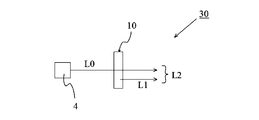
- FIG. 3 is a schematic side view showing an embodiment of the light emitting device of the present invention.
- the light emitting device according to the present embodiment is a light emitting device using a transmission type wavelength conversion member.
- the light emitting device 30 includes a wavelength conversion member 10 and a light source 4.
- the excitation light L0 emitted from the light source 4 is wavelength-converted by the wavelength conversion member 10 into fluorescence L1 having a longer wavelength than the excitation light L0. Further, part of the excitation light L0 passes through the wavelength conversion member 10. For this reason, the combined light L2 of the excitation light L0 and the fluorescence L1 is emitted from the wavelength conversion member 10.
- the excitation light L0 is blue light and the fluorescence L1 is yellow light
- white synthetic light L2 can be obtained.
- the wavelength conversion element 20 described above may be used instead of the wavelength conversion member 10.
- Examples of the light source 4 include LEDs and LDs. From the viewpoint of increasing the light emission intensity of the light emitting device 30, the light source 4 is preferably an LD capable of emitting high intensity light.
Landscapes
- Chemical & Material Sciences (AREA)
- Physics & Mathematics (AREA)
- Materials Engineering (AREA)
- Organic Chemistry (AREA)
- General Physics & Mathematics (AREA)
- Optics & Photonics (AREA)
- Engineering & Computer Science (AREA)
- Electromagnetism (AREA)
- Condensed Matter Physics & Semiconductors (AREA)
- Inorganic Chemistry (AREA)
- Luminescent Compositions (AREA)
- Led Device Packages (AREA)
- Optical Filters (AREA)
- Semiconductor Lasers (AREA)
- Compositions Of Oxide Ceramics (AREA)
Abstract
ハイパワーのLEDやLDの光を照射した場合に、経時的な発光強度の低下や構成材料の溶解を抑制することが可能な波長変換部材及び波長変換素子、並びにそれを用いた発光装置を提供する。 無機蛍光体粒子、及び、酸化マグネシウム粒子を含有する波長変換部材であって、無機蛍光体粒子間に酸化マグネシウム粒子が介在しており、かつ、無機蛍光体粒子が酸化マグネシウム粒子により結着されていることを特徴とする波長変換部材。
Description
本発明は、発光ダイオード(LED:Light Emitting Diode)やレーザーダイオード(LD:Laser Diode)等の発する光の波長を別の波長に変換する波長変換部材及び波長変換素子、並びにそれらを用いた発光装置に関する。
近年、蛍光ランプや白熱灯に変わる次世代の発光装置として、低消費電力、小型軽量、容易な光量調節という観点から、LEDやLDを用いた発光装置に対する注目が高まってきている。そのような次世代発光装置の一例として、例えば特許文献1には、青色光を出射するLED上に、LEDからの光の一部を吸収して黄色光に変換する波長変換部材が配置された発光装置が開示されている。この発光装置は、LEDから出射された青色光と、波長変換部材から出射された黄色光との合成光である白色光を発する。
波長変換部材としては、従来、樹脂マトリクス中に無機蛍光体粒子を分散させたものが用いられている。しかしながら、当該波長変換部材を用いた場合、LEDからの光により樹脂マトリクスが変色したり、変形するという問題がある。そこで、樹脂に代えてガラスマトリクス中に蛍光体を分散固定した完全無機固体からなる波長変換部材が提案されている(例えば、特許文献2及び3参照)。当該波長変換部材は、母材となるガラスマトリクスがLEDからの熱や照射光により劣化しにくく、変色や変形といった問題が生じにくいという特徴を有している。
近年、発光装置のハイパワー化を目的として、光源として用いるLEDやLDの出力が上昇している。それに伴い、光源の熱や、励起光を照射された蛍光体から発せられる熱により波長変換部材の温度が上昇し、その結果、発光強度が経時的に低下する(温度消光)という問題がある。また、場合によっては、波長変換部材の温度上昇が顕著となり、構成材料(ガラスマトリクス等)が溶解するおそれがある。
以上に鑑み、本発明は、ハイパワーのLEDやLDの光を照射した場合に、経時的な発光強度の低下や構成材料の溶解を抑制することが可能な波長変換部材及び波長変換素子、並びにそれらを用いた発光装置を提供することを目的とする。
本発明の波長変換部材は、無機蛍光体粒子、及び、酸化マグネシウム粒子を含有する波長変換部材であって、無機蛍光体粒子間に酸化マグネシウム粒子が介在しており、かつ、無機蛍光体粒子が酸化マグネシウム粒子により結着されていることを特徴とする。
本発明の波長変換部材においては、無機蛍光体粒子間に酸化マグネシウム粒子が介在している。ここで、酸化マグネシウム粒子はガラス等と比較して熱伝導性に優れているため、無機蛍光体粒子で発生した熱を効率良く外部に放出することができる。その結果、波長変換部材の温度上昇が抑制され、温度消光が生じにくくなる。また、酸化マグネシウム粒子は耐熱性にも優れるため、ハイパワーのLEDやLDの光を照射した場合であっても溶解しにくい、あるいは、急激な温度上昇によるサーマルクラックといった不具合の発生を抑制することができるという利点もある。さらに、酸化マグネシウム粒子は、酸化アルミニウムや酸化ジルコニウム等のセラミック粒子と比較して低温で焼結可能であるという利点もある。そのため、波長変換部材作製時の焼成温度も低くすることができ、焼成時における無機蛍光体粉末の劣化を抑制することができる。
本発明の波長変換部材は、質量%で、無機蛍光体粒子 3~80%、及び、酸化マグネシウム粒子 20~97%を含有することが好ましい。
本発明の波長変換部材において、酸化マグネシウム粒子の平均粒子径が0.01~10μmであることが好ましい。このようにすれば、波長変換部材の緻密性が向上して、熱伝導パスが形成されやすくなるため、無機蛍光体粒子で発生した熱をより一層効率良く外部に放出することができる。
本発明の波長変換部材において、酸化マグネシウム粒子の純度が99%以上であることが好ましい。このようにすれば、酸化マグネシウム粒子を比較的低温で焼結することが可能となる。
本発明の波長変換部材において、無機蛍光体粒子の平均粒子径が1~50μmであることが好ましい。
本発明の波長変換部材において、無機蛍光体粒子がガーネット構造を有する酸化物蛍光体からなることが好ましい。ガーネット構造を有する酸化物蛍光体は耐熱性に優れるため、ハイパワーのLEDやLDの光を照射した場合に、無機蛍光体粒子自体の劣化を抑制することができる。
本発明の波長変換部材において、(酸化マグネシウム粒子の平均粒子径)/(無機蛍光体粒子の平均粒子径)が0.5以下であることが好ましい。このようにすれば、波長変換部材の緻密性が向上して、熱伝導パスが形成されやすくなるため、無機蛍光体粒子で発生した熱をより一層効率良く外部に放出することができる。
本発明の波長変換素子は、上記の波長変換部材と、波長変換部材より高い熱伝導率を有する放熱層とが積層されてなる積層体からなることを特徴とする。このようにすれば、波長変換部材で発生した熱を放熱層に伝達することができるため、波長変換部材の温度上昇を抑制しやすくなる。
本発明の波長変換素子において、放熱層として透光性セラミックスからなるものを使用することができる。
本発明の波長変換素子において、透光性セラミックスとして、酸化アルミニウム系セラミックス、窒化アルミニウム系セラミックス、炭化ケイ素系セラミックス、窒化ホウ素系セラミックス、酸化マグネシウム系セラミックス、酸化チタン系セラミックス、酸化ニオビウム系セラミックス、酸化亜鉛系セラミックス及び酸化イットリウム系セラミックスから選択される少なくとも1種を使用することができる。
本発明の発光装置は、上記の波長変換部材と、波長変換部材に励起光を照射する光源とを備えてなることを特徴とする。
本発明の発光装置は、上記の波長変換素子と、波長変換素子に励起光を照射する光源とを備えてなることを特徴とする。
本発明の発光装置において、光源がレーザーダイオードであることが好ましい。本発明の波長変換部材及び波長変換素子は耐熱性及び放熱性に優れるため、光源として比較的ハイパワーであるレーザーダイオードを使用した場合に発明の効果を享受しやすい。
本発明によれば、ハイパワーのLEDやLDの光を照射した場合に、経時的な発光強度の低下や構成材料の溶解を抑制することが可能な波長変換部材及び波長変換素子、並びにそれらを用いた発光装置を提供することができる。
以下、本発明の実施形態を図面を用いて説明する。但し、以下の実施形態は単なる例示であり、本発明は以下の実施形態に限定されるものではない。
(波長変換部材)
図1は、本発明の波長変換部材の一実施形態を示す模式的断面図である。波長変換部材10は無機蛍光体粒子1と酸化マグネシウム粒子2を含有している。ここで、無機蛍光体粒子1間に酸化マグネシウム粒子2が介在しており、無機蛍光体粒子1が酸化マグネシウム粒子2により結着されている。
図1は、本発明の波長変換部材の一実施形態を示す模式的断面図である。波長変換部材10は無機蛍光体粒子1と酸化マグネシウム粒子2を含有している。ここで、無機蛍光体粒子1間に酸化マグネシウム粒子2が介在しており、無機蛍光体粒子1が酸化マグネシウム粒子2により結着されている。
無機蛍光体粒子1は、励起光の入射により蛍光を出射するものであれば、特に限定されるものではない。無機蛍光体粒子1の具体例としては、例えば、酸化物蛍光体、窒化物蛍光体、酸窒化物蛍光体、塩化物蛍光体、酸塩化物蛍光体、硫化物蛍光体、酸硫化物蛍光体、ハロゲン化物蛍光体、カルコゲン化物蛍光体、アルミン酸塩蛍光体、ハロリン酸塩化物蛍光体等が挙げられる。これらは単独または2種以上を混合して使用することができる。なお後述するように、波長変換部材10は無機蛍光体粒子1と酸化マグネシウム粒子2の混合粒子を焼結することにより作製されるため、無機蛍光体粒子1としては焼結時に熱劣化しないように耐熱性に優れるものが好ましい。そのような観点からは、無機蛍光体粒子1は酸化物蛍光体、特にガーネット構造を有する酸化物蛍光体(Y3Al5O12:Ce3+、Lu3Al5O12:Ce3+等)であることが好ましい。
無機蛍光体粒子1の平均粒子径(D50)は1~50μm、特に5~25μmであることが好ましい。無機蛍光体粒子1の平均粒子径が小さすぎると、発光強度が低下しやすくなる。一方、無機蛍光体粒子1の平均粒子径が大きすぎると、発光色が不均一になる傾向がある。
酸化マグネシウム粒子2の平均粒子径(D50)は0.01~10μm、特に0.05~5μm、特に0.08~1μmであることが好ましい。平均粒子径を上記範囲とすることにより、酸化マグネシウム粒子2を比較的低温で焼結することが可能となる。
酸化マグネシウム粒子2の純度は99%以上、99.9%以上、特に99.98%以上であることが好ましい。酸化マグネシウム粒子2の純度を上記範囲とすることにより、酸化マグネシウム粒子2を比較的低温で焼結することが可能となる。
上記の通り、酸化マグネシウム粒子2の平均粒子径や純度を適宜調整することにより、焼結温度を低くすることが可能となる。具体的には、1000~1400℃、1020~1250℃、さらには1050~1100℃未満の比較的低温で焼成しても緻密に焼結することができる。
酸化マグネシウム粒子2の作製方法としては、気相酸化反応による合成法や、水中火花放電法等が挙げられる。なかでも、気相酸化反応による合成法は、高純度の酸化マグネシウム粒子が得られやすいため好ましい。なお、酸化マグネシウム粒子の市販品としては、宇部マテリアルズ製の50Aや2000A等を用いることができる。
なお、(酸化マグネシウム粒子2の平均粒子径)/(無機蛍光体粒子1の平均粒子径)は0.5以下、0.2以下、0.1以下、特に0.05以下であることが好ましい。このようにすれば、波長変換部材10の緻密性が向上して、熱伝導パスが形成されやすくなるため、無機蛍光体粒子1で発生した熱をより一層効率良く外部に放出することができる。
波長変換部材10における無機蛍光体粒子1及び酸化マグネシウム粒子2の割合は、質量%で、無機蛍光体粒子1 3~80%、酸化マグネシウム粒子2 20~97%であることが好ましく、無機蛍光体粒子1 15~75%、酸化マグネシウム粒子2 25~95%であることがより好ましく、無機蛍光体粒子1 8~70%、酸化マグネシウム粒子2 30~92%であることがさらに好ましい。無機蛍光体粒子1の含有量が少なすぎる(酸化マグネシウム粒子2の含有量が多すぎる)と、波長変換部材10の発光強度が低下しやすくなる。一方、無機蛍光体粒子1の含有量が多すぎる(酸化マグネシウム粒子2の含有量が少なすぎる)と、波長変換部材10において酸化マグネシウム粒子2からなる熱伝導パスが形成されにくくなるため、無機蛍光体粒子1で発生した熱が外部に放出されにくくなる。また、無機蛍光体粒子1の結着性が低下して、波長変換部材10の機械的強度が低下しやすくなる。
波長変換部材10の形状は特に限定されないが、通常は板状(矩形板状、円盤状等)である。波長変換部材10の厚みは、目的とする色合いの光が得られるよう適宜選択することが好ましい。具体的には、波長変換部材10の厚みは2mm以下、1mm以下、特に0.8mm以下であることが好ましい。但し、波長変換部材10の厚みが小さすぎると機械的強度が低下しやすくなるため、0.03mm以上であることが好ましい。
波長変換部材10は、無機蛍光体粒子1と酸化マグネシウム粒子2を所定の割合で混合した原料粉末を予備成型した後、焼成することにより製造することができる。ここで、原料粉末に結合剤や溶剤等の有機成分を添加してペースト状にした後、焼成してもよい。このようにすれば、グリーンシート成形等の方法を利用して、所望の形状の予備成型体が形成しやすくなる。この際、まず脱脂工程(600℃程度)で有機成分を除去した後、酸化マグネシウム粒子2の焼結温度で焼成することにより、緻密な焼結体が得られやすくなる。また、1次焼成後に焼成温度±150℃でHIP(熱間静水圧プレス)処理を施しても良い。そうすることによって、波長変換部材10内の空孔を収縮させて消滅させることができ、過剰な光の散乱を抑制することができる。
結合剤としては、ポリプロピレンカーボネート、ポリブチルメタクリレート、ポリビニルブチラール、ポリメチルメタクリレート、ポリエチルメタクリレート、エチルセルロース、ニトロセルロース、ポリエステルカーボネート等が使用可能であり、これらを単独あるいは混合して使用することができる。
溶剤としては、テルピネオール、酢酸イソアミル、トルエン、メチルエチルケトン、ジエチレングリコールモノブチルエーテルアセテート、2,2,4-トリメチル-1,3-ペンタジオールモノイソブチレート等を単独または混合して使用することができる。
ペースト中には、焼結助剤が含有されていてもよい。焼結助剤としては、例えば、リン酸マグネシウム、リン酸ジルコニウム、酸化マンガン、酸化バリウム、酸化イットリウム、酸化ケイ素等の晶質粉末や、ケイ酸系やリン酸系等の酸化物非晶質粉末を用いることができる。
(波長変換素子)
図2は、本発明の波長変換素子の一実施形態を示す模式的断面図である。波長変換素子20は波長変換部材10と、波長変換部材10より高い熱伝導率を有する放熱層3とを積層させた積層体から構成されている。本実施形態では、波長変換部材10に励起光が照射されることにより発生した熱は、放熱層3を通じて外部に効率良く放出される。よって、波長変換部材10の温度が過度に上昇することを抑制することができる。
図2は、本発明の波長変換素子の一実施形態を示す模式的断面図である。波長変換素子20は波長変換部材10と、波長変換部材10より高い熱伝導率を有する放熱層3とを積層させた積層体から構成されている。本実施形態では、波長変換部材10に励起光が照射されることにより発生した熱は、放熱層3を通じて外部に効率良く放出される。よって、波長変換部材10の温度が過度に上昇することを抑制することができる。
放熱層3は、波長変換部材10より高い熱伝導率を有している。具体的には、放熱層3の熱伝導率は5W/m・K以上、10W/m・K以上、特に20W/m・K以上であることが好ましい。
放熱層3の厚みは0.05~1mm、0.07~0.8mm、特に0.1~0.5mmであることが好ましい。放熱層3の厚みが小さすぎると、機械的強度が低下する傾向がある。一方、放熱層3の厚みが大きすぎると、波長変換素子が大型化する傾向がある。
放熱層3としては透光性セラミックスからなるものを使用することができる。このようにすれば、励起光または蛍光を透過させることができるため、透過型の波長変換素子として使用することができる。透光性セラミックスからなる放熱層の波長400~800nmにおける全光線透過率は10%以上、20%以上、30%以上、40%、特に50%以上であることが好ましい。
透光性セラミックスとしては、酸化アルミニウム系セラミックス、窒化アルミニウム系セラミックス、炭化ケイ素系セラミックス、窒化ホウ素系セラミックス、酸化マグネシウム系セラミックス、酸化チタン系セラミックス、酸化ニオビウム系セラミックス、酸化亜鉛系セラミックス及び酸化イットリウム系セラミックスから選択される少なくとも1種を使用することができる。
本実施形態の波長変換素子20は、波長変換部材10の一方の主面のみに放熱層3が形成されているが、波長変換部材10の両主面に放熱層3を形成してもよい。このようにすれば、波長変換部材10で発生した熱をより一層効率よく外部に放出することができる。さらに、波長変換部材10と放熱層3とを交互に積層させた4層以上の積層体であってもよい。
なお、放熱層3としては透光性セラミックスからなるもの以外にも、Cu、Al、Ag等の金属からなる層であってもよい。このようにすれば、反射型の波長変換素子として使用することができる。
(発光装置)
図3は、本発明の発光装置の一実施形態を示す模式的側面図である。本実施形態に係る発光装置は、透過型の波長変換部材を用いた発光装置である。図3に示すように、発光装置30は、波長変換部材10と光源4を備えている。光源4から出射された励起光L0は、波長変換部材10により、励起光L0よりも波長の長い蛍光L1に波長変換される。また、励起光L0の一部は波長変換部材10を透過する。このため、波長変換部材10からは、励起光L0と蛍光L1との合成光L2が出射する。例えば、励起光L0が青色光であり、蛍光L1が黄色光である場合、白色の合成光L2を得ることができる。なお、波長変換部材10の代わりに、上記で説明した波長変換素子20を使用してもよい。
図3は、本発明の発光装置の一実施形態を示す模式的側面図である。本実施形態に係る発光装置は、透過型の波長変換部材を用いた発光装置である。図3に示すように、発光装置30は、波長変換部材10と光源4を備えている。光源4から出射された励起光L0は、波長変換部材10により、励起光L0よりも波長の長い蛍光L1に波長変換される。また、励起光L0の一部は波長変換部材10を透過する。このため、波長変換部材10からは、励起光L0と蛍光L1との合成光L2が出射する。例えば、励起光L0が青色光であり、蛍光L1が黄色光である場合、白色の合成光L2を得ることができる。なお、波長変換部材10の代わりに、上記で説明した波長変換素子20を使用してもよい。
光源4としては、LEDやLDが挙げられる。発光装置30の発光強度を高める観点からは、光源4は高強度の光を出射できるLDを用いることが好ましい。
1 無機蛍光体粒子
2 酸化マグネシウム粒子
3 放熱層
4 光源
10 波長変換部材
20 波長変換素子
30 発光装置
2 酸化マグネシウム粒子
3 放熱層
4 光源
10 波長変換部材
20 波長変換素子
30 発光装置
Claims (13)
- 無機蛍光体粒子、及び、酸化マグネシウム粒子を含有する波長変換部材であって、
無機蛍光体粒子間に酸化マグネシウム粒子が介在しており、かつ、無機蛍光体粒子が酸化マグネシウム粒子により結着されていることを特徴とする波長変換部材。 - 質量%で、無機蛍光体粒子 3~80%、及び、酸化マグネシウム粒子 20~97%を含有することを特徴とする請求項1に記載の波長変換部材。
- 酸化マグネシウム粒子の平均粒子径が0.01~10μmであることを特徴とする請求項1または2に記載の波長変換部材。
- 酸化マグネシウム粒子の純度が99%以上であることを特徴とする請求項1~3のいずれか一項に記載の波長変換部材。
- 無機蛍光体粒子の平均粒子径が1~50μmであることを特徴とする請求項1~4のいずれか一項に記載の波長変換部材。
- 無機蛍光体粒子がガーネット構造を有する酸化物蛍光体からなることを特徴とする請求項1~5のいずれか一項に記載のセラミックス波長変換部材。
- (酸化マグネシウム粒子の平均粒子径)/(無機蛍光体粒子の平均粒子径)が0.5以下であることを特徴とする請求項1~6のいずれか一項に記載の波長変換部材。
- 請求項1~7のいずれか一項に記載の波長変換部材と、波長変換部材より高い熱伝導率を有する放熱層とが積層されてなる積層体からなることを特徴とする波長変換素子。
- 放熱層が透光性セラミックスからなることを特徴とする請求項8に記載の波長変換素子。
- 透光性セラミックスが、酸化アルミニウム系セラミックス、窒化アルミニウム系セラミックス、炭化ケイ素系セラミックス、窒化ホウ素系セラミックス、酸化マグネシウム系セラミックス、酸化チタン系セラミックス、酸化ニオビウム系セラミックス、酸化亜鉛系セラミックス及び酸化イットリウム系セラミックスから選択される少なくとも1種であることを特徴とする請求項9に記載の波長変換素子。
- 請求項1~7のいずれか一項に記載の波長変換部材と、波長変換部材に励起光を照射する光源とを備えてなることを特徴とする発光装置。
- 請求項8~10のいずれか一項に記載の波長変換素子と、波長変換素子に励起光を照射する光源とを備えてなることを特徴とする発光装置。
- 光源がレーザーダイオードであることを特徴とする請求項11または12に記載の発光装置。
Applications Claiming Priority (2)
| Application Number | Priority Date | Filing Date | Title |
|---|---|---|---|
| JP2017-079488 | 2017-04-13 | ||
| JP2017079488A JP6802983B2 (ja) | 2017-04-13 | 2017-04-13 | 波長変換部材及び波長変換素子、並びにそれらを用いた発光装置 |
Publications (1)
| Publication Number | Publication Date |
|---|---|
| WO2018189997A1 true WO2018189997A1 (ja) | 2018-10-18 |
Family
ID=63792459
Family Applications (1)
| Application Number | Title | Priority Date | Filing Date |
|---|---|---|---|
| PCT/JP2018/005780 Ceased WO2018189997A1 (ja) | 2017-04-13 | 2018-02-19 | 波長変換部材及び波長変換素子、並びにそれらを用いた発光装置 |
Country Status (4)
| Country | Link |
|---|---|
| JP (1) | JP6802983B2 (ja) |
| CN (2) | CN208507721U (ja) |
| TW (1) | TW201842154A (ja) |
| WO (1) | WO2018189997A1 (ja) |
Cited By (3)
| Publication number | Priority date | Publication date | Assignee | Title |
|---|---|---|---|---|
| WO2021015261A1 (ja) * | 2019-07-22 | 2021-01-28 | 地方独立行政法人神奈川県立産業技術総合研究所 | 蛍光部材およびその製造方法、並びに発光装置 |
| CN113474439A (zh) * | 2019-04-18 | 2021-10-01 | 日本电气硝子株式会社 | 波长转换部件及其制造方法、以及发光装置 |
| CN113544236A (zh) * | 2019-04-18 | 2021-10-22 | 日本电气硝子株式会社 | 波长转换部件及其制造方法、以及发光装置 |
Families Citing this family (6)
| Publication number | Priority date | Publication date | Assignee | Title |
|---|---|---|---|---|
| JPWO2021132212A1 (ja) * | 2019-12-23 | 2021-07-01 | ||
| CN112174646A (zh) * | 2020-09-28 | 2021-01-05 | 东北大学 | 一种激光照明用高导热荧光陶瓷及其制备方法 |
| JP7535246B2 (ja) * | 2020-10-21 | 2024-08-16 | ウシオ電機株式会社 | 波長変換部材、プロジェクタ |
| JP2022185412A (ja) * | 2021-06-02 | 2022-12-14 | ウシオ電機株式会社 | 蛍光プレート及びその製造方法 |
| JP7688872B2 (ja) * | 2021-08-13 | 2025-06-05 | 地方独立行政法人神奈川県立産業技術総合研究所 | 蛍光部材およびその製造方法、並びに発光装置 |
| JP2024027406A (ja) * | 2022-08-17 | 2024-03-01 | 株式会社ワールドラボ | MgO系コンポジットセラミックス |
Citations (6)
| Publication number | Priority date | Publication date | Assignee | Title |
|---|---|---|---|---|
| JPH10195428A (ja) * | 1997-01-16 | 1998-07-28 | Toshiba Corp | 蛍光体粒子、その製造方法およびプラズマディスプレイパネル |
| JP2006059629A (ja) * | 2004-08-19 | 2006-03-02 | Matsushita Electric Ind Co Ltd | プラズマディスプレイ装置 |
| JP2009013412A (ja) * | 2007-07-06 | 2009-01-22 | Samsung Sdi Co Ltd | 金属化合物で安定化された混成化されたナノ蛍光体膜、その用途およびその製造方法 |
| JP2015088636A (ja) * | 2013-10-31 | 2015-05-07 | セイコーエプソン株式会社 | 蛍光発光素子、光源装置、およびプロジェクター |
| JP2016138020A (ja) * | 2015-01-28 | 2016-08-04 | 日本電気硝子株式会社 | 結晶化ガラス蛍光体及びそれを用いた波長変換部材 |
| JP2016204563A (ja) * | 2015-04-24 | 2016-12-08 | 太平洋セメント株式会社 | 蛍光部材、その製造方法および発光装置 |
-
2017
- 2017-04-13 JP JP2017079488A patent/JP6802983B2/ja active Active
-
2018
- 2018-02-19 WO PCT/JP2018/005780 patent/WO2018189997A1/ja not_active Ceased
- 2018-02-26 TW TW107106282A patent/TW201842154A/zh unknown
- 2018-04-12 CN CN201820515641.4U patent/CN208507721U/zh active Active
- 2018-04-12 CN CN201810325104.8A patent/CN108735877A/zh active Pending
Patent Citations (6)
| Publication number | Priority date | Publication date | Assignee | Title |
|---|---|---|---|---|
| JPH10195428A (ja) * | 1997-01-16 | 1998-07-28 | Toshiba Corp | 蛍光体粒子、その製造方法およびプラズマディスプレイパネル |
| JP2006059629A (ja) * | 2004-08-19 | 2006-03-02 | Matsushita Electric Ind Co Ltd | プラズマディスプレイ装置 |
| JP2009013412A (ja) * | 2007-07-06 | 2009-01-22 | Samsung Sdi Co Ltd | 金属化合物で安定化された混成化されたナノ蛍光体膜、その用途およびその製造方法 |
| JP2015088636A (ja) * | 2013-10-31 | 2015-05-07 | セイコーエプソン株式会社 | 蛍光発光素子、光源装置、およびプロジェクター |
| JP2016138020A (ja) * | 2015-01-28 | 2016-08-04 | 日本電気硝子株式会社 | 結晶化ガラス蛍光体及びそれを用いた波長変換部材 |
| JP2016204563A (ja) * | 2015-04-24 | 2016-12-08 | 太平洋セメント株式会社 | 蛍光部材、その製造方法および発光装置 |
Cited By (5)
| Publication number | Priority date | Publication date | Assignee | Title |
|---|---|---|---|---|
| CN113474439A (zh) * | 2019-04-18 | 2021-10-01 | 日本电气硝子株式会社 | 波长转换部件及其制造方法、以及发光装置 |
| CN113544236A (zh) * | 2019-04-18 | 2021-10-22 | 日本电气硝子株式会社 | 波长转换部件及其制造方法、以及发光装置 |
| US12140785B2 (en) | 2019-04-18 | 2024-11-12 | Nippon Electric Glass Co., Ltd. | Wavelength conversion member, production method therefor, and light-emitting device |
| WO2021015261A1 (ja) * | 2019-07-22 | 2021-01-28 | 地方独立行政法人神奈川県立産業技術総合研究所 | 蛍光部材およびその製造方法、並びに発光装置 |
| JPWO2021015261A1 (ja) * | 2019-07-22 | 2021-09-13 | 地方独立行政法人神奈川県立産業技術総合研究所 | 蛍光部材およびその製造方法、並びに発光装置 |
Also Published As
| Publication number | Publication date |
|---|---|
| TW201842154A (zh) | 2018-12-01 |
| JP6802983B2 (ja) | 2020-12-23 |
| CN208507721U (zh) | 2019-02-15 |
| CN108735877A (zh) | 2018-11-02 |
| JP2018180271A (ja) | 2018-11-15 |
Similar Documents
| Publication | Publication Date | Title |
|---|---|---|
| WO2018189997A1 (ja) | 波長変換部材及び波長変換素子、並びにそれらを用いた発光装置 | |
| WO2017098963A1 (ja) | 波長変換部材及び波長変換素子、並びにそれらを用いた発光装置 | |
| TWI497747B (zh) | 半導體發光裝置及使用該發光裝置之光源裝置 | |
| JP7268315B2 (ja) | 波長変換部材及びその製造方法、並びに発光装置 | |
| JP6512067B2 (ja) | 波長変換素子の製造方法 | |
| JP2016027613A (ja) | 波長変換部材及びそれを用いた発光装置 | |
| US20190169494A1 (en) | Wavelength conversion member | |
| CN107209302A (zh) | 波长转换部件及使用其的发光装置 | |
| JP2016225581A (ja) | 波長変換部材及びそれを用いた発光装置 | |
| JP2012185980A (ja) | 波長変換素子、それを備える光源およびその製造方法 | |
| JP6597964B2 (ja) | 波長変換部材及び波長変換素子、並びにそれを用いた発光装置 | |
| JP7469847B2 (ja) | 波長変換部材及びそれを用いた発光装置 | |
| JP6500744B2 (ja) | 波長変換素子の製造方法 | |
| JP2014112696A (ja) | 波長変換素子、及びそれを備える光源 | |
| WO2019239850A1 (ja) | 波長変換部材及び波長変換素子、並びにそれらの製造方法、並びに発光装置 | |
| JP6582907B2 (ja) | 波長変換素子の製造方法並びに波長変換素子及び発光装置 | |
| JP2023083288A (ja) | 波長変換部材及びそれを用いた発光装置 | |
| WO2019116916A1 (ja) | 波長変換部材及びその製造方法、並びに発光装置 | |
| JP6656580B2 (ja) | 波長変換部材の製造方法 | |
| JP6902373B2 (ja) | 波長変換部材およびその製造方法 | |
| JP7685454B2 (ja) | 波長変換部材、その製造方法、および発光装置 | |
| JP2021099415A (ja) | 波長変換部材および発光装置 | |
| JP6561777B2 (ja) | 波長変換素子の製造方法並びに波長変換素子及び発光装置 | |
| KR101860852B1 (ko) | 고방열 금속-형광체 경사기능복합체 및 이를 이용한 고효율 에너지 순환 레이저 라이팅 시스템 | |
| WO2021132212A1 (ja) | 波長変換部材、発光素子及び発光装置 |
Legal Events
| Date | Code | Title | Description |
|---|---|---|---|
| 121 | Ep: the epo has been informed by wipo that ep was designated in this application |
Ref document number: 18784920 Country of ref document: EP Kind code of ref document: A1 |
|
| NENP | Non-entry into the national phase |
Ref country code: DE |
|
| 122 | Ep: pct application non-entry in european phase |
Ref document number: 18784920 Country of ref document: EP Kind code of ref document: A1 |