WO2018189924A1 - 空気清浄機 - Google Patents
空気清浄機 Download PDFInfo
- Publication number
- WO2018189924A1 WO2018189924A1 PCT/JP2017/029861 JP2017029861W WO2018189924A1 WO 2018189924 A1 WO2018189924 A1 WO 2018189924A1 JP 2017029861 W JP2017029861 W JP 2017029861W WO 2018189924 A1 WO2018189924 A1 WO 2018189924A1
- Authority
- WO
- WIPO (PCT)
- Prior art keywords
- air
- touch
- air cleaner
- touch keys
- group
- Prior art date
- Legal status (The legal status is an assumption and is not a legal conclusion. Google has not performed a legal analysis and makes no representation as to the accuracy of the status listed.)
- Ceased
Links
Images





Classifications
-
- A—HUMAN NECESSITIES
- A61—MEDICAL OR VETERINARY SCIENCE; HYGIENE
- A61L—METHODS OR APPARATUS FOR STERILISING MATERIALS OR OBJECTS IN GENERAL; DISINFECTION, STERILISATION OR DEODORISATION OF AIR; CHEMICAL ASPECTS OF BANDAGES, DRESSINGS, ABSORBENT PADS OR SURGICAL ARTICLES; MATERIALS FOR BANDAGES, DRESSINGS, ABSORBENT PADS OR SURGICAL ARTICLES
- A61L9/00—Disinfection, sterilisation or deodorisation of air
- A61L9/16—Disinfection, sterilisation or deodorisation of air using physical phenomena
- A61L9/22—Ionisation
-
- A—HUMAN NECESSITIES
- A61—MEDICAL OR VETERINARY SCIENCE; HYGIENE
- A61L—METHODS OR APPARATUS FOR STERILISING MATERIALS OR OBJECTS IN GENERAL; DISINFECTION, STERILISATION OR DEODORISATION OF AIR; CHEMICAL ASPECTS OF BANDAGES, DRESSINGS, ABSORBENT PADS OR SURGICAL ARTICLES; MATERIALS FOR BANDAGES, DRESSINGS, ABSORBENT PADS OR SURGICAL ARTICLES
- A61L9/00—Disinfection, sterilisation or deodorisation of air
- A61L9/01—Deodorant compositions
- A61L9/014—Deodorant compositions containing sorbent material, e.g. activated carbon
-
- F—MECHANICAL ENGINEERING; LIGHTING; HEATING; WEAPONS; BLASTING
- F24—HEATING; RANGES; VENTILATING
- F24F—AIR-CONDITIONING; AIR-HUMIDIFICATION; VENTILATION; USE OF AIR CURRENTS FOR SCREENING
- F24F11/00—Control or safety arrangements
- F24F11/50—Control or safety arrangements characterised by user interfaces or communication
-
- F—MECHANICAL ENGINEERING; LIGHTING; HEATING; WEAPONS; BLASTING
- F24—HEATING; RANGES; VENTILATING
- F24F—AIR-CONDITIONING; AIR-HUMIDIFICATION; VENTILATION; USE OF AIR CURRENTS FOR SCREENING
- F24F11/00—Control or safety arrangements
- F24F11/50—Control or safety arrangements characterised by user interfaces or communication
- F24F11/52—Indication arrangements, e.g. displays
-
- F—MECHANICAL ENGINEERING; LIGHTING; HEATING; WEAPONS; BLASTING
- F24—HEATING; RANGES; VENTILATING
- F24F—AIR-CONDITIONING; AIR-HUMIDIFICATION; VENTILATION; USE OF AIR CURRENTS FOR SCREENING
- F24F11/00—Control or safety arrangements
- F24F11/50—Control or safety arrangements characterised by user interfaces or communication
- F24F11/56—Remote control
-
- F—MECHANICAL ENGINEERING; LIGHTING; HEATING; WEAPONS; BLASTING
- F24—HEATING; RANGES; VENTILATING
- F24F—AIR-CONDITIONING; AIR-HUMIDIFICATION; VENTILATION; USE OF AIR CURRENTS FOR SCREENING
- F24F8/00—Treatment, e.g. purification, of air supplied to human living or working spaces otherwise than by heating, cooling, humidifying or drying
- F24F8/10—Treatment, e.g. purification, of air supplied to human living or working spaces otherwise than by heating, cooling, humidifying or drying by separation, e.g. by filtering
-
- F—MECHANICAL ENGINEERING; LIGHTING; HEATING; WEAPONS; BLASTING
- F24—HEATING; RANGES; VENTILATING
- F24F—AIR-CONDITIONING; AIR-HUMIDIFICATION; VENTILATION; USE OF AIR CURRENTS FOR SCREENING
- F24F8/00—Treatment, e.g. purification, of air supplied to human living or working spaces otherwise than by heating, cooling, humidifying or drying
- F24F8/10—Treatment, e.g. purification, of air supplied to human living or working spaces otherwise than by heating, cooling, humidifying or drying by separation, e.g. by filtering
- F24F8/108—Treatment, e.g. purification, of air supplied to human living or working spaces otherwise than by heating, cooling, humidifying or drying by separation, e.g. by filtering using dry filter elements
-
- F—MECHANICAL ENGINEERING; LIGHTING; HEATING; WEAPONS; BLASTING
- F24—HEATING; RANGES; VENTILATING
- F24F—AIR-CONDITIONING; AIR-HUMIDIFICATION; VENTILATION; USE OF AIR CURRENTS FOR SCREENING
- F24F8/00—Treatment, e.g. purification, of air supplied to human living or working spaces otherwise than by heating, cooling, humidifying or drying
- F24F8/30—Treatment, e.g. purification, of air supplied to human living or working spaces otherwise than by heating, cooling, humidifying or drying by ionisation
-
- A—HUMAN NECESSITIES
- A61—MEDICAL OR VETERINARY SCIENCE; HYGIENE
- A61L—METHODS OR APPARATUS FOR STERILISING MATERIALS OR OBJECTS IN GENERAL; DISINFECTION, STERILISATION OR DEODORISATION OF AIR; CHEMICAL ASPECTS OF BANDAGES, DRESSINGS, ABSORBENT PADS OR SURGICAL ARTICLES; MATERIALS FOR BANDAGES, DRESSINGS, ABSORBENT PADS OR SURGICAL ARTICLES
- A61L2209/00—Aspects relating to disinfection, sterilisation or deodorisation of air
- A61L2209/10—Apparatus features
- A61L2209/11—Apparatus for controlling air treatment
- A61L2209/111—Sensor means, e.g. motion, brightness, scent, contaminant sensors
-
- A—HUMAN NECESSITIES
- A61—MEDICAL OR VETERINARY SCIENCE; HYGIENE
- A61L—METHODS OR APPARATUS FOR STERILISING MATERIALS OR OBJECTS IN GENERAL; DISINFECTION, STERILISATION OR DEODORISATION OF AIR; CHEMICAL ASPECTS OF BANDAGES, DRESSINGS, ABSORBENT PADS OR SURGICAL ARTICLES; MATERIALS FOR BANDAGES, DRESSINGS, ABSORBENT PADS OR SURGICAL ARTICLES
- A61L2209/00—Aspects relating to disinfection, sterilisation or deodorisation of air
- A61L2209/10—Apparatus features
- A61L2209/12—Lighting means
-
- A—HUMAN NECESSITIES
- A61—MEDICAL OR VETERINARY SCIENCE; HYGIENE
- A61L—METHODS OR APPARATUS FOR STERILISING MATERIALS OR OBJECTS IN GENERAL; DISINFECTION, STERILISATION OR DEODORISATION OF AIR; CHEMICAL ASPECTS OF BANDAGES, DRESSINGS, ABSORBENT PADS OR SURGICAL ARTICLES; MATERIALS FOR BANDAGES, DRESSINGS, ABSORBENT PADS OR SURGICAL ARTICLES
- A61L2209/00—Aspects relating to disinfection, sterilisation or deodorisation of air
- A61L2209/10—Apparatus features
- A61L2209/14—Filtering means
-
- F—MECHANICAL ENGINEERING; LIGHTING; HEATING; WEAPONS; BLASTING
- F24—HEATING; RANGES; VENTILATING
- F24F—AIR-CONDITIONING; AIR-HUMIDIFICATION; VENTILATION; USE OF AIR CURRENTS FOR SCREENING
- F24F2120/00—Control inputs relating to users or occupants
- F24F2120/10—Occupancy
Definitions
- the present invention relates to an air cleaner provided with a touch key.
- Patent Document 1 discloses a conventional air cleaner.
- This air cleaner has a housing that opens a suction port and a blow-out port.
- An operation panel provided with capacitive touch keys is provided on the top of the housing.
- An air passage that connects the suction port and the air outlet is provided in the housing, and a blower is disposed in the air passage.
- a filter is arranged facing the inlet.
- the blower when the operation is started, the blower is driven and air in the room is sucked from the suction port.
- the air sucked from the suction port is sent out from the air outlet after dust is collected by the filter. Thereby, the air cleaning in a living room can be performed.
- An operation panel having a capacitance type touch key generally has a plurality of light sources corresponding to the touch keys, and a sheet provided with characters and the like that can be transmitted between the touch keys and the light sources.
- the touch key is displayed so as to be visible by turning on the light source, and the user can recognize the desired touch key on the operation panel and perform an operation input.
- the light source of the touch key is always turned on, which causes a problem that the power consumption of the air cleaner increases.
- An object of the present invention is to provide an air cleaner that can reduce power consumption.
- the present invention provides a housing that opens a suction port and a blowout port, an air passage that connects the suction port and the blowout port, a blower disposed in the air passage,
- an air cleaner comprising a filter arranged facing the suction port, a plurality of touch keys and an operation panel having a plurality of light sources corresponding to the touch keys, and performing an air cleaning operation by driving the blower
- the present invention further includes a communication unit that performs wireless communication, and the light source of the touch key of the second group different from the first group is always lit, and the second group of the air cleaner It is preferable that the touch key includes a communication key for instructing whether communication by the communication unit is possible.
- the light sources of the touch keys of the second group different from the first group are always lit, and the touch keys of the second group start the air cleaning operation. And a start key for instructing stoppage.
- the light amount of the light source is increased when the touch key that lights the light source is operated.
- the air cleaner configured as described above, it is preferable that a function different from that when the predetermined touch key is pressed for a short time is assigned when the predetermined touch key is pressed for a long time, and the light source blinks when the key is pressed for a long time.
- the present invention preferably includes the third group of touch keys that turn on the light source by operating the first group of touch keys.
- the operation panel may include a notification unit that is displayed when the display light source is turned on, and the display light source is turned off when the human body detection unit does not detect a person. It is preferable to light up or blink when a person is detected.
- a human body detection unit that detects the presence or absence of a person is provided in the casing of the air cleaner, and the human body detection unit turns off the light when the light source of the predetermined first group of touch keys does not detect a person. Lights up or flashes when detected. Thereby, when the human body detection unit does not detect a person, the light sources of the first group of touch keys can be turned off, and the power consumption of the air cleaner can be reduced.
- Side surface sectional drawing which shows the air cleaner of 1st Embodiment of this invention.
- the block diagram which shows the air cleaner of 1st Embodiment of this invention.
- the top view which shows the operation panel of the air cleaner of 1st Embodiment of this invention.
- Side surface sectional drawing which shows the notification area
- the top view which shows the display pattern of the operation panel of the air cleaner of 1st Embodiment of this invention.
- the top view which shows the operation panel of the air cleaner of 2nd Embodiment of this invention.
- the top view which shows the display pattern of the operation panel of the air cleaner of 2nd Embodiment of this invention.
- FIG.1 and FIG.2 has shown the front view and side sectional drawing of the air cleaner of 1st Embodiment.
- the arrow S indicates the air flow.
- the air cleaner 1 has a housing 2 that is installed on a floor surface or the like in a living room by opening a suction port 3 and air outlets 4 and 5.
- the housing 2 has a main body portion 20 and a cover portion 21.
- the cover part 21 is detachably arranged on the back surface of the main body part 20 and opens the suction port 3.
- the main body 20 opens the air outlets 4 and 5 at the upper front surface and the upper surface, respectively.
- An operation panel 30 is disposed in front of the upper surface of the main body 20.
- the air outlets 4 and 5 are respectively provided with wind direction plates 14 and 15 that change the wind direction.
- the wind direction plate 14 is formed of a flat plate and is supported by a rotation shaft portion (not shown) provided on the wind direction plate 14 so as to be rotatable in the vertical direction.
- a plurality of vertical louvers 14 a are vertically arranged on the lower surface of the wind direction plate 14 in the left-right direction.
- the vertical louvers 14a at both ends are inclined outward in the left-right direction as they go forward.
- the wind direction plate 15 is formed of a flat plate and is supported by a rotation shaft portion 15b provided at the front portion of the wind direction plate 15 so as to be rotatable in the vertical direction.
- a plurality of vertical louvers 15 a are vertically arranged in the left-right direction on the lower surface of the wind direction plate 15.
- the vertical louvers 15a at both ends are inclined outward in the left-right direction as they go backward.
- the wind direction plates 14 and 15 close the air outlets 4 and 5 when the operation of the air purifier 1 is stopped, and open the air outlets 4 and 5 during operation.
- An air passage 8 that connects the suction port 3 and the blowout ports 4 and 5 is provided in the housing 2.
- a pre-filter (filter) 6 a deodorizing filter 7, a dust collecting filter 9, a humidifying unit 200, a blower are sequentially arranged from the suction port 3 toward the blowout ports 4 and 5 (from the upstream to the downstream of the airflow).
- An ion generator 11 and a damper 12 are provided.
- the air passage 8 has a first branch passage 8 a and a second branch passage 8 b that branch downstream from the ion generator 11.
- the first branch passage 8a and the second branch passage 8b communicate with the outlets 4 and 5, respectively, and the cross-sectional area of the air flow path of the first branch passage 8a is larger than the cross-sectional area of the air flow path of the second branch passage 8b. Is also getting smaller.
- the damper 12 is formed in a thin plate shape, and is supported by the rotation shaft portion 12a so as to be rotatable in the vertical direction.
- the damper 12 can be rotated in the direction of opening the first branch passage 8a from the closed position (see FIG. 2) (counterclockwise direction in FIG. 2).
- the damper 12 changes the air volume balance of the first branch passage 8a and the second branch passage 8b.
- the blower 10 is formed by a centrifugal fan such as a sirocco fan driven by a motor 10a, and sucks in an axial direction and exhausts in a circumferential direction.
- a centrifugal fan such as a sirocco fan driven by a motor 10a
- the prefilter 6 is formed of a sheet-like mesh such as polypropylene, and is disposed on the cover portion 21 so as to face the suction port 3.
- the pre-filter 6 can collect large dust in the intake air.
- the deodorizing filter 7 is formed in a honeycomb shape and can adsorb odor components in the air to deodorize the air.
- the dust collection filter 9 is composed of a HEPA filter, and a frame material (not shown) is welded by hot melt so as to cover the filter material (not shown).
- the dust collection filter 9 can collect fine dust in the air and fine particles such as PM2.5 and pollen having a particle diameter smaller than a predetermined particle diameter (for example, 3 ⁇ m).
- the humidification unit 20 includes a tray 201, a humidification filter 202, and a float switch 120.
- the float switch 120 detects the water level of the tray 201, and when a drop in the water level is detected, water is supplied from the tank to the tray 201.
- the humidifying filter 202 is movably arranged between a position where the tray 201 is immersed in water and a position where it is not immersed. When the humidification operation is turned on, the humidification filter 202 is immersed in the water of the tray 201, and the air passing through the humidification filter 202 is humidified. When the humidifying operation is turned off, the humidifying filter 202 is disposed at a position where it is not immersed in the water of the tray 201, and the air passing through the humidifying filter 202 is not humidified.
- the ion generator 11 has an ion generation surface 11 a that generates ions when a high voltage is applied, and the ion generation surface 11 a faces the air passage 8.
- a voltage having an AC waveform or an impulse waveform is applied to the ion generation surface 11a.
- the applied voltage of the ion generating surface 11a is a positive voltage
- positive ions mainly composed of H + (H 2 O) m are generated.
- the applied voltage is negative, negative ions mainly composed of O 2 ⁇ (H 2 O) n are generated.
- m and n are integers.
- H + (H 2 O) m and O 2 ⁇ (H 2 O) n aggregate on the surface of airborne bacteria and odor components and surround them.
- active species [ ⁇ OH] hydroxyl radical
- H 2 O 2 hydrogen peroxide
- m ′ and n ′ are integers. Therefore, sterilization and odor removal in the room can be performed by generating positive ions and negative ions and sending them out from the outlets 4 and 5.
- the cover unit 21 is provided with a cleaning device 400 for cleaning the prefilter 6.
- the cleaning device 400 moves the prefilter 6 up and down by driving the drive motor 100, and removes dust on the prefilter 6 by the brush body 80. Further, the removed dust is collected in a container 92 disposed below the brush body 80.
- FIG. 3 is a block diagram showing the configuration of the air purifier 1.
- the air cleaner 1 has a control unit 300 that controls each unit.
- the control unit 300 includes a display unit 17, a notification unit 18, an operation unit 19, a blower 10, an ion generator 11, a drive motor 100, a storage unit 101, an illuminance sensor 102, a dust sensor 103, an odor sensor 104, a human body detection unit 105, A temperature sensor 106, a humidity sensor 107, a notification unit 108, a communication unit 109, and a float switch 120 are connected.
- the control unit 300 reads and executes a control program stored in advance in the storage unit 101 by a control processor such as a CPU or MPU. Thereby, drive / stop of the display part 17, the notification part 18, the operation part 19, the air blower 10, the ion generator 11, the drive motor 100, the communication part 109, and the float switch 120 can be controlled.
- a control processor such as a CPU or MPU.
- the storage unit 101 stores the control program for the air purifier 1, and the calculation results by the control unit 300 and the detection results of the illuminance sensor 102, dust sensor 103, odor sensor 104, human body detection unit 105, temperature sensor 106, and humidity sensor 107.
- the control program for the air purifier 1 stores the control program for the air purifier 1, and the calculation results by the control unit 300 and the detection results of the illuminance sensor 102, dust sensor 103, odor sensor 104, human body detection unit 105, temperature sensor 106, and humidity sensor 107.
- the communication unit 109 performs wireless communication according to the WiFi standard. Thereby, input operation of the air cleaner 1 can be performed via external apparatuses, such as a personal computer (not shown). In addition, the communication unit 109 can download and update a new control program via the communication network 110.
- the illuminance sensor 102, the temperature sensor 106 and the humidity sensor 107 detect the illuminance, temperature and humidity in the room where the air purifier 1 is installed.
- the dust sensor 103 detects the dust density in the air.
- the odor sensor 104 is disposed in the vicinity of the suction port 3 and detects the concentration of odor components (odor concentration) in the air.
- the human body detection unit 105 includes, for example, any one of an infrared sensor, an ultrasonic sensor, a visible light sensor, a camera, and an illuminance sensor 102, and detects the presence of a person within a predetermined distance range from the air cleaner 1.
- the controller 300 determines the presence of a person in the room based on the output obtained from the human body detector 105.
- the notification unit 108 is constituted by a speaker and notifies voice guidance.
- FIG. 4 shows a plan view of the operation panel 30.
- the operation panel 30 includes a notification unit 18 and an operation unit 19.
- the notification unit 18 and the operation unit 19 are so-called light-emitting character displays except for the touch keys 30a, and the LED 34 (see FIGS. 5 and 6) arranged on the back side with a figure (icon) or a character string is turned on to emerge. Can be displayed. Further, by turning off the LED 34, the display on the operation panel 30 can be eliminated, and the design can be improved.
- the notification unit 18 has a plurality of notification areas 32a to 32g, and a figure (icon) or a character string arranged in each area is lit and displayed to indicate the state of the air cleaner 1 to the user.
- the operation unit 19 has a plurality of touch keys 30a to 30l, and the operation setting of the air cleaner 1 is performed by a user's operation.
- the touch key 30a is formed by printing a figure on a front panel 35 (FIG. 6), which will be described later, and is not lit.
- a figure (icon) or a character string arranged in each operation area is lit and displayed to accept a user's operation input.
- the touch keys 30b to 30e and the touch key 30h are respectively provided with lamps 31b to 31e and 31h on the upper left.
- the lamps 31b to 31e and 31h are turned on to notify the user that the operations of the touch keys 30b to 30e and the touch key 30h are being performed.
- the touch key 30a is a start key, and instructs the operation and stop of the air purifier 1 by operating the touch key 30a.
- the touch key 30b executes the “steady circulation automatic mode”. By the operation of the touch key 30b, the “steady circulation automatic mode” is started, and the lamp 31b is turned on. In the “Fully-automated circulation mode”, the humidification operation is performed so that the humidity is 55% to 65% while automatically adjusting the air volume based on the detection results of the dust sensor 103, the odor sensor 104, the temperature sensor 106, and the humidity sensor 107. Do.
- Touch key 30c executes “effect realization mode”.
- the “effect actual feeling mode” is started, and the lamp 31c is turned on.
- the “effect realization mode” the air volume is increased for a predetermined time and the airflow direction plates 14 and 15 are rotated backward to cause the airflow blown from the outlet 5 to be short-circuited to the inlet 3. Thereby, the dust around the air cleaner 1 can be intensively drawn into the suction port 3.
- the airflow is blown forward while the wind direction plates 14 and 15 are rotated forward to drive the ion generator 11. Thereby, deodorization and sterilization in front of the air cleaner 1 can be performed intensively.
- Touch key 30d executes “vacuum cleaner assist mode”.
- the “vacuum cleaner assist mode” is started, and the lamp 31d is turned on.
- the airflow direction plate 14 is rotated forward for a predetermined time to blow an airflow downward from the air outlet 4 and the air outlet plate 15 is closed by the airflow direction plate 15. Further, the air volume is increased to the maximum while the ion generator 11 is driven without humidification. Thereby, airflow is blown out toward the installation surface of the air cleaner 1, and it prevents that the dust which rose by the exhaust_gas
- the wind direction plate 15 is rotated rearward to blow an air flow rearward and upward from the air outlet 5 and the air outlet plate 14 is closed by the air direction plate 14. Thereby, the airflow blown out from the blowout port 5 is short-circuited to the suction port 3, and dust that has risen when the vacuum cleaner is used is rapidly collected.
- Touch key 30e executes “powerful shot mode”.
- the “powerful shot mode” is started and the lamp 31e is turned on.
- the air volume is increased while the ion generator 11 is driven.
- the wind direction plates 14 and 15 are rotated forward, and the airflow blown out from the outlets 4 and 5 is directed forward. Thereby, it concentrates in front of the housing 2 and discharge
- the touch keys 30f to 30k are used when the normal air cleaning operation different from the “steady circulation auto mode”, “effect actual feeling mode”, “vacuum cleaner assist mode” or “powerful shot mode” is being executed. Can be set.
- the touch key 30f is a key for both the wind direction setting operation and the child lock operation.
- the touch key 30f is pressed for a short time, the rotational position of the wind direction plates 14 and 15 is fixed at a predetermined position and the outlets 4 and 5 are fixed. It is possible to change the direction of the airflow that blows out.
- the child lock is set or released.
- the “key mark” placed in the notification area 32a and the “child lock (pressed for 3 seconds)” placed in the notification area 32b are lit and the operation of the touch keys 30a to 30k is disabled. become.
- the touch key 30g combines an operation for setting the air volume and an operation for setting the drive of the ion generator 11.
- eight patterns of air volumes can be set.
- six patterns of characters are arranged in the notification area 32c above the touch key 30g, and the characters arranged in the notification area 32c are turned on according to the set air volume setting pattern.
- the air volume setting patterns are specifically eight patterns of “auto”, “pollen”, “night”, “silent”, “weak”, “medium”, “strong”, “turbo”, and the touch key 30g is pressed. Each time the air volume setting pattern is changed. When the air volume is set to “automatic”, the air volume is automatically set based on the detection results of the illuminance sensor 102, dust sensor 103, odor sensor 104, human body detection unit 105, temperature sensor 106, and humidity sensor 107.
- the air volume is set to “pollen”
- the sensitivity of the dust sensor 103 is set high, dust and pollen are quickly detected, and the air volume is increased more than the “automatic” setting to collect pollen and dust in the room.
- the air volume is automatically set based on the detection results of the illuminance sensor 102, the dust sensor 103, the odor sensor 104, the temperature sensor 106, and the humidity sensor 107. Also reduce the air volume and drive quietly.
- the driving of the ion generator 11 can be switched to ON or OFF.
- the “plasma cluster ion lamp” (not shown) of the display unit 17 is turned on, and when the driving of the ion generator 11 is turned off, the “plasma cluster ion lamp” (not shown). Goes off.
- the touch key 30h is an operation key for setting a maintenance time notification for the tank (not shown) of the humidifying unit 200, the tray 201, and the humidifying filter 202.
- the setting of the cleaning time notification of the humidifying unit 200 is set to “ON”.
- the operating time of the air cleaning operation is integrated to elapse a predetermined time (for example, 720 hours) and the time that the float switch 120 is in the “ON” state is integrated to elapse the predetermined time (60 minutes).
- a “humidification and care” letter placed in the notification area 32d is lit. Thereby, a user is alert
- the touch key 30h is pressed and held for 3 seconds or longer, the word “humidification and care” is turned off, and the accumulated time of the air cleaning operation and the accumulated time of the time when the float switch 120 is in the “ON” state are reset. .
- the touch key 30i is an operation key for setting or canceling the automatic cleaning of the prefilter 6.
- a “prefilter cleaning lamp” (not shown) on the display unit 17 is lit. To do. Further, the cleaning device 400 is automatically driven to clean the pre-filter 6 when the accumulated time of the air cleaning operation has passed a predetermined time (for example, 48 hours).
- the “pre-filter cleaning lamp” (not shown) on the display unit 17 is turned off. Further, the cleaning device 400 is forcibly driven to clean the prefilter 6 when a predetermined time (for example, 720 hours) elapses in the accumulated time of the air cleaning operation.
- the touch key 30i also serves as a reset operation for discarding the dust accumulated in the container 92.
- the touch key 30i When the touch key 30i is pressed for 3 seconds or longer, the setting of the notification of the disposal time of the dust accumulated in the container 92 is reset. Thereby, after the reset, when the accumulated time of the air cleaning operation has passed a predetermined time (eg, 4320 hours), the characters “garbage stealth” placed in the notification area 32e and the “reset ( "Press for 3 seconds)” lights up. This notifies the user that it is time to discard the dust accumulated in the container 92.
- a predetermined time eg, 4320 hours
- the touch key 30j is an operation key for switching the display of the display unit 17, and any one of “temperature”, “humidity”, “PM2.5 concentration”, and “electricity charge” is displayed on the display unit 17 by the operation of the touch key 30j.
- the state of the air around the air cleaner 1 can be displayed by switching.
- “Temperature” indicates the temperature (° C.) detected by the temperature sensor 106.
- “Humidity” displays the humidity (%) detected by the humidity sensor 107.
- “PM2.5 concentration” indicates the concentration ( ⁇ g / m 3 ) detected by the dust sensor 103.
- “Electricity cost” displays the amount of money (yen) calculated from the operating time of the air cleaning operation.
- the touch key 30k is a volume setting operation key, and when the touch key 30k is pressed for a short time, the volume of the voice guidance notified from the notification unit 108 can be changed. In addition, when the touch key 30k is pressed for 3 seconds or longer, the voice guidance can be switched between “ON” and “OFF”. When the voice guidance is set to “ON”, the characters “volume (press for 3 seconds)” in the notification area 32g are lit. Further, when the voice guidance is set to “OFF”, the characters “volume (press for 3 seconds)” in the notification area 32g are turned off.
- the touch key 30l is a communication key for instructing whether communication by the communication unit 109 is possible, and can be switched by pressing the touch key 30l for 3 seconds or longer. Further, when the communication unit 109 is in a communicable state, a “connect lamp” (not shown) of the display unit 17 is turned on, and when the communication unit 109 is in a state where communication is not possible, the “connect lamp” is turned off.
- FIG. 5 is a side sectional view showing a notification area of the operation panel. Note that the notification areas 32a to 32g have the same structure, and the notification area 32a will be described as a representative.
- the notification area 32 a includes a substrate 33, an LED 34, and a front panel 35.
- the substrate 33 is a printed wiring board, and the LEDs 34 are mounted on the upper surface.
- the front panel 35 is disposed above the LED 34.
- the front panel 35 includes a diffusing member 35a, a light shielding member 35b, and a light transmitting member 35c, and the light shielding member 35b is disposed between the diffusion member 35a and the light transmitting member 35c.
- the diffusing member 35a diffuses incident light and suppresses unevenness in brightness (brightness unevenness) of light transmitted through the surface panel 35.
- the light shielding member 35b is colored black and blocks light emitted from the LED 34.
- the light shielding member 35b has a slit 35d that forms a graphic or character string arranged in the notification area 32a.
- the translucent member 35c is disposed on the uppermost surface of the front panel 35 and protects the light shielding member 35b.
- the translucent member 35c is formed of a material having high light transmittance such as glass, acrylic resin, polycarbonate resin or the like.
- the translucent member 35c is made of a transparent material, and looks black when the front panel 35 is viewed from the outside.
- the slit 35d has no light transmitted upward from below, so that the display of the notification area 32a can be eliminated.
- FIG. 6 is a side sectional view showing the touch keys on the operation panel. Note that the touch keys 30b to 30l have the same structure, and the touch key 30b will be described as a representative.
- the touch key 30 b includes a substrate 33, an LED 34, a front panel 35, an electrostatic sensor 36, a conductive member 37, a lens 38, and a fixing member 39.
- the front panel 35 has the same configuration as that of the notification area 32a and will not be described. As the touch key 30b is also turned on, the figure and the characters appear to be raised by the light passing through the slit 35d.
- the lens 38 is disposed above the LED 34 and expands the irradiation range of the light emitted from the LED 34.
- the fixing member 39 fixes the lens 38.
- the fixing member 39 has a mortar-shaped through hole 39a, and holds the lens 38 by bringing the lower surface of the lens 38 into contact with the inclined surface 39b of the through hole 39a.
- the fixing member 39 is fixed to the front panel 35.
- the electrostatic sensor 36 has an annular shape and is mounted on the substrate 33 so as to surround the LED.
- a conductive member 37 is disposed between the electrostatic sensor 36 and the lens 38 and between the electrostatic sensor 36 and the fixing member 39.
- the electrostatic sensor 36 is a sensor that detects accumulated charges.
- the electrostatic sensor 36 forms a capacitor with the user's finger that contacts the front panel 35 and the conductive member 37, and detects the electric charge accumulated in the capacitor. That is, a change in capacitance accumulated in the capacitor is detected to detect contact or separation of the user's finger with the surface panel 35.
- the control unit 300 determines that the operation of the touch panel 30b has been performed.
- the touch key 30a includes the substrate 33, the front panel 35, the electrostatic sensor 36, the conductive member 37, and the fixing member 39, but does not include the LED 34 and the lens 38. .
- the front panel 35 is not provided with a slit 35d.
- a figure (icon) is printed on the lower surface of the translucent member 35c. Otherwise, the touch key 30a has the same configuration as the touch key 30b.
- the touch key 30a is printed and displayed on the operation panel 30 regardless of whether the air cleaner 1 is turned on or off. For this reason, when the power supply of the air cleaner 1 is ON, the operation of the air cleaner 1 can be easily started or stopped, and convenience is improved.
- FIG. 7 is a plan view showing a display pattern of the operation panel, and shows a state where the human body detection unit 105 does not detect the presence of a person. Further, the touch keys 30l that are lit are indicated by solid lines, and the touch keys 30a that are printed and displayed are indicated by broken lines.
- the control unit 300 determines that there is no person who operates the operation unit 19 around the air cleaner 1. At this time, the control unit 300 turns off all the LEDs 34 of the touch keys 30b to 30k (first group touch keys) and the LED 34 (display light source) of the notification unit 18, and sets the touch keys 30l (second group touch keys). Only the LED 34 is lit.
- the user can recognize the touch key 30l that is lit and the touch key 30a that is printed and displayed. For this reason, the user can easily start or stop the operation of the air purifier 1 and the convenience is improved. Further, the power consumption can be reduced by turning off the LEDs 34 of the first group of touch keys 30b to 30k. In addition, the display of the touch keys 30b to 30k on the surface of the operation panel 30 can be eliminated to improve the design.
- the control unit 300 determines that there is a person who operates the operation unit 19 around the air cleaner 1. At this time, when one of the “steady circulation auto mode”, “effect actual feeling mode”, “vacuum cleaner assist mode”, or “powerful shot mode” is executed, the control unit 300 performs the touch key of the mode being executed. 30b-30e and lamps 31b-31e are turned on.
- the control unit 300 lights all the LEDs 34 of the touch keys 30b to 30k.
- the user can perform any operation while accurately viewing the touch keys 30a to 30k of the operation unit 19.
- the LEDs 34 corresponding to the notification areas 32a to 32g of the notification unit 18 are also turned on. Thereby, when a person is not within the predetermined range with respect to the housing 2 of the air purifier 1, it is determined that the notification unit 18 is not seen, and the LED 34 of the notification unit 18 is turned off to further reduce power consumption. be able to.
- the light source of the LED 34 increases.
- the user can recognize that the operation of the predetermined touch keys 30b to 30l is being executed, and the convenience can be improved.
- the touch keys 30f to 30i and the touch key 30k are assigned different functions when they are pressed for a long time.
- the corresponding LED 34 blinks. Thereby, the user can recognize that the long press operation is being executed, and can improve convenience.
- the air in the living room is sucked from the suction port 3 and flows through the ventilation passage 8. At this time, large dust is collected in the air by the pre-filter 6.
- air is deodorized by the deodorizing filter 7, and fine dust, PM2.5, pollen and other fine particles in the air are collected by the dust collecting filter 9.
- the air containing ions is blown into the living room from one or both of the outlets 4 and 5. Thereby, the ventilation operation
- the cleaning device 400 is driven and the cleaning operation by the cleaning device 400 is started.
- the drive motor 100 rotates to move the prefilter 6 up and down, and the brush body 80 slides on the prefilter 6. Thereby, the dust on the pre-filter 6 is removed, and the dust is collected in the container 92.
- the user can remove the dust collecting part 90 from the cover part 21 and discard the dust accumulated in the container 92.
- the human body detection unit that detects the presence or absence of a person in the casing 2 105, and the LED 34 of the predetermined first group of touch keys 30b to 30k is turned off when no person is detected by the human body detection unit 105 and is turned on when a person is detected.
- the LEDs 34 of the first group of touch keys 30b to 30k can be turned off to reduce power consumption.
- the LED 34 of the second group touch key 30l different from the first group is always lit, and the touch key 301 is a communication key for instructing whether communication by the communication unit 109 performing wireless communication is possible. Accordingly, since the LED 34 of the touch key 30 is always lit, even when the air cleaning operation is stopped, the touch key 301 can be easily operated to set whether communication is possible, and convenience is improved.
- the touch keys 30b to 30l whose LEDs 34 are lit are operated, the user can recognize that the operation of the predetermined touch keys 30b to 30l is executed by increasing the amount of light of the LEDs 34, which is convenient. Can be improved.
- the touch keys 30f to 30i and the touch key 30k are assigned different functions when they are pressed for a long time.
- the corresponding LED 34 blinks. Thereby, the user can recognize that the long press operation is being executed, and can improve convenience.
- the operation panel 30 has the notification unit 18 displayed by turning on the LED 34 (light source for display), and the LED 34 of the notification unit 18 is turned off when the human body detection unit 105 does not detect a person and detects a person Lights up.
- LED34 of the notification part 18 can be light-extinguished and power consumption can be reduced more.
- FIG. 8 is a plan view of the operation panel of the air cleaner of the present embodiment.
- the same reference numerals are given to the same parts as those in the first embodiment shown in FIGS.
- This embodiment is different from the first embodiment in that a touch key 30m is provided on the operation unit 19.
- Other parts are the same as those in the first embodiment.
- the touch key 30m is an operation key for displaying a menu, and the operation of the touch key 30m can be executed in any one of “steady circulation automatic mode”, “effect actual feeling mode”, “vacuum cleaner assist mode” or “powerful shot mode”. If it is, the touch keys 30b to 30e and the lamps 31b to 31e in the currently executed mode are turned on.
- the control unit 300 turns on all the LEDs 34 of the touch keys 30b to 30k.
- the user performs a predetermined operation from the lit touch keys 30b to 30k to set the operation of the air cleaner 1. Further, after a predetermined time (10 seconds) has passed since the operation of the touch key 30m, when there is no operation of the touch keys 30b to 30k, all the touch keys 30b to 30k are turned off.
- FIG. 9 is a plan view showing a display pattern on the operation panel of the air purifier, and shows a state in which the human body detection unit 105 detects the presence of a person.
- the touch keys 30l and 30m that are lit are indicated by solid lines, and the touch keys 30a that are printed are indicated by broken lines.
- the control unit 300 lights only the LED 34 of the first group of touch keys 30m.
- the notification unit 18 and the operation unit 19 are not lit and displayed unless the user touches the touch key 30l.
- the human body detection part 105 detects presence of a person, the number of LED34 which turns on can be reduced, and power consumption can be reduced more.
- the human body detection unit 105 lights up when it detects the presence of a person.
- the power consumption can be further reduced by reducing the number of LEDs 34.
- FIG. 10 is a plan view showing a display pattern of the operation panel of the air cleaner of the present embodiment, and shows a state where the human body detection unit does not detect the presence of a person.
- the touch keys 30a and 30l that are lit are indicated by solid lines.
- the same reference numerals are given to the same parts as those in the first embodiment shown in FIGS.
- This embodiment is different from the first embodiment in that the touch key 30a is lit and displayed, and the touch key 30a is included in the second group of touch keys. Other parts are the same as those in the first embodiment.
- the touch key 30a has an LED 34, and when the LED 34 is turned on, the figure (icon) of the touch key 30a appears to be raised by the light passing through the slit 35d.
- the control unit 300 turns off the LEDs 34 of the touch keys 30b to 30l (first group touch keys) on the operation panel 30 and touches the touch keys 30a and 30m (second group). Only the touch key is lit.
- the touch key 30a may be a combination of lighting display and print display. Thereby, the user can grasp
- the present invention is not limited to the above-described embodiments, and various modifications are possible. Embodiments obtained by appropriately combining technical means disclosed in different embodiments are also included in the present invention. Included in the technical scope.
- the touch keys 30a to 30m may use a resistance film method other than the capacitance method, or an electromagnetic induction method.
- first group touch keys and the third group touch keys need not be all of the touch keys 30b to 30k, and any one of the touch keys 30b to 30k may be arbitrarily selected. Further, all the second group touch keys may be printed. In this case, the user can accurately grasp the position of the touch key printed and displayed in the same manner as the touch key always lighted.
- the LED 34 (light source) corresponding to the first group touch key and the third group touch key or the LED 34 (display light source) of the notification unit 18 blinks when the human body detection unit 105 detects the presence of a person. May be.
- the user can be alerted by blinking the LED 34 corresponding to the key or the LED 34 of the notification unit 18.
- the light source of the first group to third group touch keys is not limited to the LED 34 arranged immediately below each touch key.
- a light source provided around the first group to third group touch keys may be provided as a light source corresponding to the touch keys.
- the human body detection unit 105 detects the presence of a person
- the light source provided around the touch key is turned on or blinked, so that the user can grasp in advance based on the light source that is turned on or blinking.
- a predetermined touch key can be selected and operated from the arrangement of the touch keys.
- the present invention can be used for an air cleaner equipped with a touch key for performing input by contact with a user's finger or the like.
Landscapes
- Engineering & Computer Science (AREA)
- Chemical & Material Sciences (AREA)
- Combustion & Propulsion (AREA)
- Mechanical Engineering (AREA)
- General Engineering & Computer Science (AREA)
- Human Computer Interaction (AREA)
- Health & Medical Sciences (AREA)
- Epidemiology (AREA)
- Life Sciences & Earth Sciences (AREA)
- Animal Behavior & Ethology (AREA)
- General Health & Medical Sciences (AREA)
- Public Health (AREA)
- Veterinary Medicine (AREA)
- Materials Engineering (AREA)
- Air Conditioning Control Device (AREA)
- Disinfection, Sterilisation Or Deodorisation Of Air (AREA)
Abstract
本発明は、吸込口3及び吹出口4、5を開口する筐体2と、吸込口3と吹出口4、5とを連結する空気通路8と、空気通路8内に配される送風機10と、吸込口3に面して配されるプレフィルタ6と、複数のタッチキー30b~30m及び各タッチキー30b~30mに対応する複数の光源34を有した操作パネル30とを備え、送風機10の駆動により空気清浄運転を行う空気清浄機1において、筐体2に人の有無を検知する人体検知部105を設け、所定の第1群のタッチキー30mのLED34が人体検知部105により人を検知しないときに消灯して人を検知したときに点灯又は点滅する。
Description
本発明は、タッチキーを備えた空気清浄機に関する。
特許文献1には従来の空気清浄機が開示されている。この空気清浄機は吸込口及び吹出口を開口する筐体を有する。筺体の上部には静電容量式のタッチキーを配した操作パネルが設けられている。筐体内には吸込口と吹出口とを連結する空気通路が設けられ、空気通路内には送風機が配される。吸込口に面してフィルタが配される。
上記構成の空気清浄機において、運転が開始されると、送風機が駆動されて吸込口から居室内の空気が吸い込まれる。吸込口から吸い込まれた空気はフィルタにより塵埃が捕集された後に吹出口から送出される。これにより、居室内の空気清浄を行うことができる。
静電容量式のタッチキーを有した操作パネルは一般に、各タッチキーに対応する複数の光源を有し、タッチキーと光源との間に文字等を透過可能に設けたシートが配される。光源の点灯によりタッチキーが視認可能に表示され、使用者が操作パネル上の所望のタッチキーを認識して操作入力を行うことができる。
しかしながら、上記従来の空気清浄機によると、タッチキーの光源が常時点灯するため、空気清浄機の消費電力が高くなる問題があった。
本発明は、消費電力を低減できる空気清浄機を提供することを目的とする。
上記目的を達成するために本発明は、吸込口及び吹出口を開口する筐体と、前記吸込口と前記吹出口とを連結する空気通路と、前記空気通路内に配される送風機と、前記吸込口に面して配されるフィルタと、複数のタッチキー及び各前記タッチキーに対応する複数の光源を有した操作パネルとを備え、前記送風機の駆動により空気清浄運転を行う空気清浄機において、前記筐体に人の有無を検知する人体検知部を設け、所定の第1群の前記タッチキーの前記光源が前記人体検知部により人を検知しないときに消灯して人を検知したときに点灯又は点滅することを特徴としている。
また、本発明は、上記構成の空気清浄機において、無線通信を行う通信部を備え、前記第1群と異なる第2群の前記タッチキーの前記光源が常時点灯し、前記第2群の前記タッチキーが前記通信部による通信可否を指示する通信キーを含むと好ましい。
また、本発明は、上記構成の空気清浄機において、前記第1群と異なる第2群の前記タッチキーの前記光源が常時点灯し、前記第2群の前記タッチキーが前記空気清浄運転の開始及び停止を指示するスタートキーを含むと好ましい。
また、本発明は、上記構成の空気清浄機において、前記光源を点灯した前記タッチキーが操作された際に、前記光源の光量を増加させると好ましい。
また、本発明は、上記構成の空気清浄機において、所定の前記タッチキーが短押し時と異なる機能を長押し時に割り当てられ、長押し時に前記光源を点滅させると好ましい。
また、本発明は、上記構成の空気清浄機において、前記第1群の前記タッチキーの操作により前記光源が点灯される第3群の前記タッチキーを有すると好ましい。
また、本発明は、上記構成の空気清浄機において、前記操作パネルが表示用光源の点灯により表示される通知部を有し、前記表示用光源が前記人体検知部により人を検知しないときに消灯して人を検知したときに点灯又は点滅すると好ましい。
本発明によると、空気清浄機の筐体に人の有無を検知する人体検知部を設け、所定の第1群のタッチキーの光源が人体検知部により人を検知しないときに消灯して人を検知したときに点灯又は点滅する。これにより、人体検知部が人を検知しない場合に第1群のタッチキーの光源を消灯し、空気清浄機の消費電力を低減することができる。
<第1実施形態>
以下に図面を参照して本発明の実施形態を説明する。図1及び図2は第1実施形態の空気清浄機の正面図及び側面断面図を示している。なお、矢印Sは空気の流れを示している。空気清浄機1は吸込口3及び吹出口4、5を開口して居室内の床面等に設置される筐体2を有する。
以下に図面を参照して本発明の実施形態を説明する。図1及び図2は第1実施形態の空気清浄機の正面図及び側面断面図を示している。なお、矢印Sは空気の流れを示している。空気清浄機1は吸込口3及び吹出口4、5を開口して居室内の床面等に設置される筐体2を有する。
筐体2は本体部20及びカバー部21を有する。カバー部21は本体部20の背面に対して着脱可能に配され、吸込口3を開口する。本体部20は吹出口4、5をそれぞれ前面上部及び上面に開口する。本体部20の上面前部には操作パネル30が配される。
吹出口4、5には風向を可変する風向板14、15がそれぞれ設けられる。風向板14は平板から成り、風向板14に設けられた回動軸部(不図示)により上下方向に回動可能に支持される。風向板14の下面には複数の縦ルーバ14aが左右方向に並んで垂設される。両側端部の縦ルーバ14aは前方へ行くほど左右方向の外方に傾斜している。
風向板15は平板から成り、風向板15の前部に設けられた回動軸部15bにより上下方向に回動可能に支持される。風向板15の下面には複数の縦ルーバ15aが左右方向に並んで垂設される。両側端部の縦ルーバ15aは後方へ行くほど左右方向の外方に傾斜している。
風向板14、15は空気清浄機1の運転停止時にそれぞれ吹出口4、5を閉じ、運転時に吹出口4、5を開く。
筐体2内には吸込口3と吹出口4、5とを連結する空気通路8が設けられる。空気通路8内には吸込口3から吹出口4、5に向かって(気流の上流から下流に向かって)順にプレフィルタ(フィルタ)6、脱臭フィルタ7、集塵フィルタ9、加湿部200、送風機10、イオン発生装置11及びダンパ12が設けられる。
空気通路8はイオン発生装置11の下流で分岐する第1分岐通路8a及び第2分岐通路8bを有する。第1分岐通路8a及び第2分岐通路8bはそれぞれ吹出口4、5に連通し、第1分岐通路8aの空気の流路の断面積は第2分岐通路8bの空気の流路の断面積よりも小さくなっている。
ダンパ12は薄板状に形成され、回動軸部12aにより上下方向に回動可能に支持される。ダンパ12は第1分岐通路8aを閉じた位置(図2参照)から開く方向(図2において、反時計回り方向)に回動することができる。ダンパ12により第1分岐通路8a及び第2分岐通路8bの風量バランスが可変される。
送風機10はモータ10aにより駆動されるシロッコファン等の遠心ファンにより形成され、軸方向に吸気して周方向に排気する。
プレフィルタ6はポリプロピレン等のシート状のメッシュにより形成され、吸込口3に面してカバー部21に配される。プレフィルタ6によって吸気中の大きな塵埃を捕集することができる。
脱臭フィルタ7はハニカム状に形成され、空気中の臭気成分を吸着して空気を脱臭することができる。
集塵フィルタ9はHEPAフィルタから成り、濾材(不図示)を覆うように枠材(不図示)がホットメルトにより溶着される。集塵フィルタ9によって空気中の微細な塵埃や所定粒径(例えば3μm)よりも小さい粒径のPM2.5や花粉等の微小粒子を捕集することができる。
加湿部20はトレイ201、加湿フィルタ202及びフロートスイッチ120を有している。フロートスイッチ120はトレイ201の水位を検知し、水位の低下を検知するとタンクからトレイ201に給水される。加湿フィルタ202はトレイ201の水に浸漬される位置と浸漬されない位置とを可動に配される。加湿運転がオンされると加湿フィルタ202がトレイ201の水に浸漬され、加湿フィルタ202を通過する空気が加湿される。加湿運転がオフされると加湿フィルタ202がトレイ201の水に浸漬されない位置に配され、加湿フィルタ202を通過する空気の加湿が行われない。
イオン発生装置11は高圧電圧の印加によりイオンを発生するイオン発生面11aを有し、イオン発生面11aは空気通路8内に面している。イオン発生面11aには交流波形またはインパルス波形から成る電圧が印加される。イオン発生面11aの印加電圧が正電圧の場合は主としてH+(H2O)mから成るプラスイオンを発生し、負電圧の場合は主としてO2
-(H2O)nから成るマイナスイオンを発生する。ここで、m、nは整数である。H+(H2O)m及びO2
-(H2O)nは空気中の浮遊菌や臭気成分の表面で凝集してこれらを取り囲む。
そして、式(1)~(3)に示すように、衝突により活性種である[・OH](水酸基ラジカル)やH2O2(過酸化水素)を微生物等の表面上で凝集生成して浮遊菌等を破壊する。ここで、m’、n’は整数である。したがって、プラスイオン及びマイナスイオンを発生して吹出口4、5から送出することにより居室内の除菌及び臭い除去を行うことができる。
H+(H2O)m+O2
-(H2O)n→・OH+1/2O2+(m+n)H2O ・・・(1)
H+(H2O)m+H+(H2O)m’+O2 -(H2O)n+O2 -(H2O)n’
→ 2・OH+O2+(m+m'+n+n')H2O ・・・(2)
H+(H2O)m+H+(H2O)m’+O2 -(H2O)n+O2 -(H2O)n’
→ H2O2+O2+(m+m'+n+n')H2O ・・・(3)
H+(H2O)m+H+(H2O)m’+O2 -(H2O)n+O2 -(H2O)n’
→ 2・OH+O2+(m+m'+n+n')H2O ・・・(2)
H+(H2O)m+H+(H2O)m’+O2 -(H2O)n+O2 -(H2O)n’
→ H2O2+O2+(m+m'+n+n')H2O ・・・(3)
カバー部21にはプレフィルタ6を清掃する清掃装置400が設けられる。清掃装置400は駆動モータ100の駆動によりプレフィルタ6を上下に移動させ、ブラシ体80によりプレフィルタ6上の塵埃を除去する。また、除去された塵埃はブラシ体80の下方に配された容器92に回収される。
図3は空気清浄機1の構成を示すブロック図である。空気清浄機1は各部を制御する制御部300を有している。制御部300には表示部17、通知部18、操作部19、送風機10、イオン発生装置11、駆動モータ100、記憶部101、照度センサ102、ホコリセンサ103、ニオイセンサ104、人体検知部105、温度センサ106、湿度センサ107、報知部108、通信部109、フロートスイッチ120が接続される。
制御部300はCPUやMPUなどの制御プロセッサにより記憶部101にあらかじめ格納されている制御プログラムを読み出して実行する。これにより、表示部17、通知部18、操作部19、送風機10、イオン発生装置11、駆動モータ100、通信部109、フロートスイッチ120の駆動・停止を制御することができる。
記憶部101は空気清浄機1の制御プログラムを格納するとともに、制御部300による演算結果や照度センサ102、ホコリセンサ103、ニオイセンサ104、人体検知部105、温度センサ106、湿度センサ107の検知結果を記憶する。
通信部109はWiFi規格による無線通信を行う。これにより、パーソナルコンピュータ(不図示)等の外部機器を介して空気清浄機1の入力操作を行うことができる。また、通信部109は通信網110を介して新しい制御プログラムをダウンロードしてアップデートすることができる。
照度センサ102、温度センサ106及び湿度センサ107は空気清浄機1が設置された室内の照度、温度及び湿度をそれぞれ検知する。
ホコリセンサ103は空気中のホコリ密度を検知する。ニオイセンサ104は吸込口3の近傍に配され、空気中の臭気成分の濃度(臭気濃度)を検知する。
人体検知部105は例えば赤外線センサ、超音波センサ、可視光センサ、カメラ、照度センサ102のいずれかから成り、空気清浄機1から所定距離範囲以内の人の存在を検知する。制御部300は人体検知部105から得られる出力に基づいて室内の人の存在を判定する。
報知部108はスピーカにより構成され、音声ガイダンスを報知する。
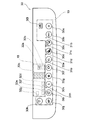
図4は操作パネル30の平面図を示している。操作パネル30は通知部18と操作部19とを備えている。
通知部18及び操作部19はタッチキー30aを除いていわゆる発光式の文字表示であり、図形(アイコン)又は文字列を背面に配されたLED34(図5、図6参照)を点灯して浮かび上がらせて表示することができる。また、LED34を消灯することにより、操作パネル30上の表示を無くすことができ、意匠性を高めることができる。
通知部18は複数の通知領域32a~32gを有し、各領域に配された図形(アイコン)又は文字列が点灯表示されて空気清浄機1の状態が使用者に示される。
操作部19は複数のタッチキー30a~30lを有し、使用者の操作によって空気清浄機1の動作設定が行われる。タッチキー30aは後述する表面パネル35(図6)に図形が印刷されて形成され、点灯表示されない。一方、タッチキー30b~30lは各操作領域に配された図形(アイコン)又は文字列が点灯表示して使用者の操作入力を受け付ける。
タッチキー30b~30e、タッチキー30hには左上にランプ31b~31e、31hが夫々設けられる。ランプ31b~31e、31hの点灯によりタッチキー30b~30e、タッチキー30hの操作が各々実行されていることを使用者に知らせる。
タッチキー30aはスタートキーであり、タッチキー30aの操作により、空気清浄機1の運転及び停止を指示する。
タッチキー30bは「しっかり循環おまかせモード」を実行する。タッチキー30bの操作により、「しっかり循環おまかせモード」が開始され、ランプ31bが点灯する。「しっかり循環おまかせモード」では、ホコリセンサ103、ニオイセンサ104、温度センサ106及び湿度センサ107の検知結果に基づいて自動で風量を調整しながら湿度が55%~65%になるように加湿運転を行う。
タッチキー30cは「効果実感モード」を実行。タッチキー30cの操作により、「効果実感モード」が開始され、ランプ31cが点灯する。「効果実感モード」では、所定時間、風量を強くするとともに風向板14、15を後方に回動して吹出口5から吹出した気流を吸込口3にショートサーキットさせる。これにより、空気清浄機1の周囲の塵埃を吸込口3へ集中的に引き込むことができる。
また、「効果実感モード」では、「効果実感モード」の開始から所定時間経過後、風向板14、15を前方に回動してイオン発生装置11を駆動しながら、前方に気流を吹き出す。これにより、空気清浄機1の前方の消臭・除菌を集中的に行うことができる。
タッチキー30dは「掃除機アシストモード」を実行する。タッチキー30dの操作により、「掃除機アシストモード」が開始され、ランプ31dが点灯する。「掃除機アシストモード」では、所定時間、風向板14を前方に回動して吹出口4から前方下方に気流を吹出すとともに風向板15により吹出口5を閉じる。また、加湿を行わずにイオン発生装置11を駆動しながら、風量を最大に上げる。これにより、気流が空気清浄機1の設置面に向かって吹出され、掃除機の排気で舞い上がった塵埃を設置面に付着するのを防ぐ。
また、「掃除機アシストモード」の開始から所定時間経過後に風向板15を後方に回動して吹出口5から後方上方に気流を吹出すとともに風向板14により吹出口4を閉じる。これにより、吹出口5から吹出した気流を吸込口3にショートサーキットさせて掃除機を使用した際に舞い上がったホコリを急速で集塵する。
タッチキー30eは「パワフルショットモード」を実行する。タッチキー30eの操作により、「パワフルショットモード」が開始され、ランプ31eが点灯する。「パワフルショットモード」では、イオン発生装置11を駆動しながら、風量を強くする。また、風向板14、15を前方に回動して吹出口4、5から吹出す気流を前方に向ける。これにより、筺体2の前方に集中して高濃度のプラスイオン及びマイナスイオンを放出し、筺体2の前方に配した対象物に付着した臭いや菌を除去することができる。
タッチキー30f~30kは「しっかり循環おまかせモード」、「効果実感モード」、「掃除機アシストモード」又は「パワフルショットモード」とは異なる通常の空気清浄運転が実行されている場合に風向、風量等の設定を行うことができる。
タッチキー30fは風向設定の操作とチャイルドロックの操作とを兼用するキーであり、タッチキー30fを短押しすると、風向板14、15の回動位置を所定位置に固定して吹出口4、5から吹出す気流の向きを変更することができる。
また、タッチキー30fを3秒間以上長押しするとチャイルドロックの設定又は解除が実行される。チャイルドロックを設定した場合、通知領域32aに配される「鍵マーク」と通知領域32bに配される「チャイルドロック(3秒押し)」の文字が点灯してタッチキー30a~30kの操作が無効になる。
タッチキー30gは風量を設定する操作とイオン発生装置11の駆動を設定する操作とを兼用する。タッチキー30gを短押しすると、8パターンの風量を設定することができる。また、タッチキー30gの上方には通知領域32cに6パターンの文字が配されており、設定された風量設定パターンに応じて通知領域32cに配された文字が点灯する。
風量設定パターンは具体的に、「自動」、「花粉」、「おやすみ」、「静音」、「弱」、「中」、「強」、「ターボ」の8パターンであり、タッチキー30gを押すたびに順に風量設定パターンが変更される。風量を「自動」に設定した場合、照度センサ102、ホコリセンサ103、ニオイセンサ104、人体検知部105、温度センサ106、湿度センサ107の検知結果に基づいて風量が自動的に設定される。
また、風量を「花粉」に設定した場合、ホコリセンサ103の感度を高く設定し、埃や花粉を素早く検知して「自動」設定よりも風量を上げて室内の花粉及び埃を集塵する。
また、風量を「おやすみ」に設定した場合、照度センサ102、ホコリセンサ103、ニオイセンサ104、温度センサ106、湿度センサ107の検知結果に基づいて風量が自動的に設定され、「自動」設定よりも風量を下げて、静音で運転する。
また、風量を「静音」、「弱」、「中」、「強」、「ターボ」が設定された場合、順に風量が大きくなる。
また、タッチキー30gを3秒間以上長押しするとイオン発生装置11の駆動をON又はOFFに切り替えることができる。イオン発生装置11の駆動をONにすると、表示部17の「プラズマクラスターイオンランプ」(不図示)が点灯し、イオン発生装置11の駆動をOFFにすると、「プラズマクラスターイオンランプ」(不図示)が消灯する。
タッチキー30hは加湿部200のタンク(不図示)、トレイ201及び加湿フィルタ202のお手入れ時期通知を設定する操作キーである。タッチキー30hの操作により、加湿部200のお手入れ時期通知の設定が「ON」になる。これにより、空気清浄運転の運転時間が積算して所定時間(例えば、720時間)を経過するとともにフロートスイッチ120が「ON」の状態にある時間が積算して所定時間(60分)を経過したときに通知領域32dに配された「加湿お手入れ」の文字が点灯する。これにより、加湿部200がお手入れ時期であることを使用者に報知する。
また、タッチキー30hを3秒以上長押しすると、「加湿お手入れ」の文字が消灯し、空気清浄運転の積算時間及びフロートスイッチ120が「ON」の状態にある時間の積算時間がリセットされる。
タッチキー30iはプレフィルタ6の自動掃除の設定又は解除を行う操作キーであり、タッチキー30iの操作により、自動掃除を設定すると、表示部17の「プレフィルタ掃除ランプ」(不図示)が点灯する。また、空気清浄運転の積算時間が所定時間(例えば、48時間)を経過したときに自動的に清掃装置400が駆動してプレフィルタ6を掃除する。
また、タッチキー30iの操作により、自動掃除を解除すると、表示部17の「プレフィルタ掃除ランプ」(不図示)が消灯する。また、空気清浄運転の積算時間が所定時間(例えば、720時間)を経過したときに強制的に清掃装置400が駆動してプレフィルタ6を掃除する。
なお、清掃装置400が駆動中は空気清浄運転を中止して、タッチキー30iが点滅する。
また、タッチキー30iは容器92に溜まった塵埃廃棄時期のリセット操作も兼用している。タッチキー30iを3秒間以上長押しすると、容器92に溜まった塵埃の廃棄時期通知の設定がリセットされる。これにより、リセット後、空気清浄運転の積算時間が所定時間(例えば、4320時間)を経過したときに通知領域32eに配された「ごみすて」の文字と通知部32fに配された「リセット(3秒押し)」の文字が点灯する。これにより、容器92に溜まった塵埃の廃棄時期であることを使用者に報知する。
また、再びタッチキー30iを3秒間以上長押しすると、「ごみすて」の文字と「リセット(3秒押し)」の文字は消灯する。
タッチキー30jは表示部17の表示切替の操作キーであり、タッチキー30jの操作により、表示部17に「温度」、「湿度」、「PM2.5濃度」、「電気代」のいずれかを切り替えて空気清浄機1の周囲の空気の状態を表示することができる。
「温度」は温度センサ106により検知された温度(℃)を表示する。「湿度」は湿度センサ107により検知された湿度(%)を表示する。「PM2.5濃度」はホコリセンサ103により検知された濃度(μg/m3)を表示する。「電気代」は空気清浄運転の運転時間から算出した金額(円)を表示する。
タッチキー30kは音量設定の操作キーであり、タッチキー30kを短押しすると、報知部108から報知される音声ガイダンスの音量を変更することができる。また、タッチキー30kを3秒以上長押しすると、音声ガイダンスの「ON」と「OFF」とを切り替えることができる。音声ガイダンスが「ON」に設定されたとき、通知領域32gの「音量(3秒押し)」の文字が点灯する。また、音声ガイダンスが「OFF」に設定されたとき、通知領域32gの「音量(3秒押し)」の文字が消灯する。
タッチキー30lは通信部109による通信可否を指示する通信キーであり、タッチキー30lを3秒以上長押して、通信可否を切り替えることができる。また、通信部109が通信可能な状態にあるとき、表示部17の「コネクトランプ」(不図示)が点灯し、通信部109が通信不能な状態にあるとき、「コネクトランプ」は消灯する。
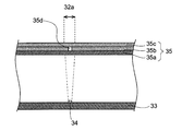
図5は操作パネルの通知領域を示す側面断面図である。なお、通知領域32a~32gは同様の構造を有しており、代表して通知領域32aについて説明する。通知領域32aは基板33と、LED34と表面パネル35とを備えている。基板33はプリント配線基板であり、上面にLED34を実装する。また、表面パネル35はLED34の上方に配されている。
表面パネル35は拡散部材35aと、遮光部材35bと、透光部材35cとを備え、拡散部材35aと透光部材35cとの間に遮光部材35bが配されている。
拡散部材35aは入射する光を拡散させて表面パネル35を透過する光の輝度の偏り(輝度むら)を抑制する。
遮光部材35bは黒色に着色されており、LED34から出射された光を遮断する。遮光部材35bは通知領域32aに配される図形又は文字列を形成するスリット35dが開口している。
透光部材35cは表面パネル35の最上面に配され、遮光部材35bを保護している。透光部材35cはガラス、アクリル樹脂、ポリカーボネイト樹脂等の光の透過率が高い材料で形成されている。透光部材35cは透明材料から成り、表面パネル35を外側から見たときに遮光部材35bの黒色に見える。
LED34を点灯すると、通知領域32a内のスリット35dを光が通過してスリット35d以外の部分は遮光部材35bで光が遮断される。これにより、スリット35dを通過する光によって図形及び文字が浮かび上がって見える。
一方、LED34を消灯するとスリット35dは下方から上方に透過する光が無いため通知領域32aの表示を無くすことができる。
図6は操作パネルのタッチキーを示す側面断面図である。なお、タッチキー30b~30lは同一の構造を有しており、代表してタッチキー30bについて説明する。タッチキー30bは基板33と、LED34と、表面パネル35と、静電センサ36と、導電部材37と、レンズ38と、固定部材39とを備えている。
なお、表面パネル35は通知領域32aと共通の構成であり、説明を省略する。タッチキー30bもLED34の点灯により、スリット35dを通過する光によって図形及び文字が浮かび上がって見える。
レンズ38はLED34の上方に配され、LED34から出射された光の照射範囲を拡大する。
固定部材39はレンズ38を固定する。固定部材39はすり鉢状の貫通孔39aを有しており、貫通孔39aの傾斜面39bにレンズ38の下面を接触させてレンズ38を保持している。また、固定部材39は表面パネル35に固定されている。
静電センサ36は円環状であり、LEDの周囲を囲んで基板33に実装されている。また、静電センサ36とレンズ38及び静電センサ36と固定部材39との間には導電部材37が配されている。
静電センサ36は蓄積された電荷を検知するセンサである。静電センサ36は、表面パネル35に接触する使用者の指と導電部材37とでコンデンサを構成し、コンデンサに蓄積される電荷を検知する。つまり、コンデンサに蓄積される静電容量の変化を検知して、使用者の指の表面パネル35への接触又は離間を検出する。静電センサ36が使用者の接触を検出したときに制御部300がタッチパネル30bの操作が行われたと判定する。
また、タッチキー30aはタッチキー30bと同様に基板33と、表面パネル35と、静電センサ36と、導電部材37と、固定部材39とを備えているが、LED34及びレンズ38を備えていない。また、表面パネル35にはスリット35dが設けられていない。透光部材35cの下面に図形(アイコン)が印刷されている。それ以外はタッチキー30aもタッチキー30bと同一の構成から成る。
また、タッチキー30aは印刷表示されており、空気清浄機1の電源がONであるかOFFであるかにかかわらず、操作パネル30上に常に表示される。このため、空気清浄機1の電源がONである場合、空気清浄機1の運転を容易に開始又は停止することができ利便性が向上する。
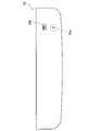
図7は操作パネルの表示パターンを示す平面図であり、人体検知部105が人の存在を検知しない状態を示している。また、点灯表示されたタッチキー30lを実線で示し、印刷表示されたタッチキー30aは破線で示す。
人体検知部105が人の存在を検知しない場合、制御部300は空気清浄機1の周囲に操作部19を操作する人がいないと判定する。このとき、制御部300はタッチキー30b~30k(第1群のタッチキー)のLED34及び通知部18のLED34(表示用光源)を全て消灯し、タッチキー30l(第2群のタッチキー)のLED34のみを点灯する。
これにより、使用者は点灯表示されたタッチキー30lと印刷表示されたタッチキー30aを認識することができる。このため、使用者は空気清浄機1の運転を容易に開始又は停止することができ利便性が向上する。また、第1群のタッチキー30b~30kのLED34を消灯して消費電力を低減することができる。また、操作パネル30表面にタッチキー30b~30kの表示を無くして意匠性を高めることができる。
また、人体検知部105が人の存在を検知した場合、制御部300は空気清浄機1の周囲に操作部19を操作する人がいると判定する。このとき、制御部300は「しっかり循環おまかせモード」、「効果実感モード」、「掃除機アシストモード」又は「パワフルショットモード」のいずれかが実行されている場合、実行されているモードのタッチキー30b~30eとランプ31b~31eとを点灯させる。
一方、「しっかり循環おまかせモード」、「効果実感モード」、「掃除機アシストモード」又は「パワフルショットモード」のいずれのモードも実行されておらず、通常の空気清浄運転が実行されている場合、制御部300はタッチキー30b~30kのLED34を全て点灯する。これにより、使用者は操作部19のタッチキー30a~30kを正確に視認していずれかの操作をおこなうことができる。
また、人体検知部105が人の存在を検知した場合、通知部18の通知領域32a~32gに対応するLED34も点灯する。これにより、人が空気清浄機1の筐体2に対して所定範囲内に無い場合に、通知部18は見られないと判定し、通知部18のLED34を消灯して消費電力をより低減することができる。
また、点灯されたタッチキー30b~30lを使用者が操作した際に、LED34の光源が増加する。これにより、使用者は所定のタッチキー30b~30lの操作が実行されていることを認識でき、利便性を向上することができる。
また、タッチキー30f~30i及びタッチキー30kは短押し時と異なる機能を長押し時に割り当てられている。タッチキー30f~30i及びタッチキー30kのいずれかを3秒以上長押ししたとき対応するLED34が点滅する。これにより、使用者は長押し操作が実行されていることを認識でき、利便性を向上することができる。
また、タッチキー30aを操作して通常の空気清浄運転が開始されると、吸込口3から居室内の空気が吸い込まれて送風通路8を流通する。この時、プレフィルタ6により空気中に大きな塵埃が捕集される。また、脱臭フィルタ7により空気が脱臭され、集塵フィルタ9により空気中の微細な塵埃やPM2.5、花粉等の微小粒子が捕集される。
そして、イオン発生装置11により発生したイオンが空気に含まれる。イオンを含んだ空気は吹出口4、5の一方または両方から居室内に吹き出される。これにより、空気清浄機1の送風動作が行われ、居室内の空気清浄が行われる。
また、所定の時期になると、清掃装置400が駆動されて清掃装置400による清掃動作が開始される。
清掃装置400が駆動されると駆動モータ100が回転し、プレフィルタ6を上下に移動させブラシ体80がプレフィルタ6を摺動する。これにより、プレフィルタ6上の塵埃が除去され、塵埃は容器92内に集塵される。
駆動モータ100の回転量が所定値に到達すると、駆動モータ100が停止される。以上により、清掃装置400による清掃動作が終了する。
清掃装置400による清掃動作の終了後に、使用者は集塵部90をカバー部21から取り外し、容器92に溜まった塵埃を廃棄することができる。
本実施形態によると、複数のタッチキー30b~30l及び各タッチキー30b~30lに対応する複数のLED34(光源)を有した操作パネル30において、筐体2に人の有無を検知する人体検知部105を設け、所定の第1群のタッチキー30b~30kのLED34が人体検知部105により人を検知しないときに消灯して人を検知したときに点灯する。これにより、人が空気清浄機1の筐体2に対して所定範囲内に無い場合に、第1群のタッチキー30b~30kのLED34を消灯して消費電力を低減することができる。
また、第1群と異なる第2群のタッチキー30lのLED34が常時点灯し、タッチキー30lは無線通信を行う通信部109による通信可否を指示する通信キーである。これにより、タッチキー30のLED34が常時点灯するにより、空気清浄運転が停止されている場合においてもタッチキー30lを操作して容易に通信可否の設定を行うことができ、利便性が向上する。
また、LED34が点灯したタッチキー30b~30lが操作された際に、LED34の光量を増加させることにより、使用者は所定のタッチキー30b~30lの操作が実行されていることを認識でき、利便性を向上することができる。
また、タッチキー30f~30i及びタッチキー30kは短押し時と異なる機能を長押し時に割り当てられている。タッチキー30f~30i及びタッチキー30kのいずれかを長押ししたとき対応するLED34が点滅する。これにより、使用者は長押し操作が実行されていることを認識でき、利便性を向上することができる。
また、操作パネル30がLED34(表示用光源)の点灯により表示される通知部18を有し、通知部18のLED34が人体検知部105により人を検知しないときに消灯して人を検知したときに点灯する。これにより、人が空気清浄機1の筐体2に対して所定範囲内に無い場合に、通知部18のLED34を消灯して消費電力をより低減することができる。
<第2実施形態>
次に、本発明の第2実施形態について説明する。図8は本実施形態の空気清浄機の操作パネルの平面図である。説明の便宜上、前述の図1~7に示した第1実施形態と同様の部分には同一の符号を付している。本実施形態では、操作部19にタッチキー30mが設けられている点が第1実施形態とは異なっている。その他の部分は第1実施形態と同様である。
次に、本発明の第2実施形態について説明する。図8は本実施形態の空気清浄機の操作パネルの平面図である。説明の便宜上、前述の図1~7に示した第1実施形態と同様の部分には同一の符号を付している。本実施形態では、操作部19にタッチキー30mが設けられている点が第1実施形態とは異なっている。その他の部分は第1実施形態と同様である。
タッチキー30mはメニュー表示を行う操作キーであり、タッチキー30mの操作により、「しっかり循環おまかせモード」、「効果実感モード」、「掃除機アシストモード」又は「パワフルショットモード」のいずれかが実行されている場合、実行されているモードのタッチキー30b~30eとランプ31b~31eとを点灯させる。
一方、「しっかり循環おまかせモード」、「効果実感モード」、「掃除機アシストモード」又は「パワフルショットモード」とは異なる通常の空気清浄運転が実行されている場合、使用者がタッチキー30lをタッチすると、制御部300はタッチキー30b~30kのLED34を全て点灯する。
これにより、使用者は点灯したタッチキー30b~30kから所定の操作を行って空気清浄機1の動作設定を行う。また、タッチキー30mの操作から所定時間(10秒)経過後、タッチキー30b~30kの操作がない場合に、タッチキー30b~30kを全て消灯する。
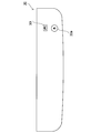
図9は空気清浄機の操作パネルの表示パターンを示す平面図であり、人体検知部105が人の存在を検知した状態を示している。また、点灯表示されたタッチキー30l、30mを実線で示し、印刷表示されたタッチキー30aは破線で示す。
人体検知部105が人の存在を検知した場合、制御部300は第1群のタッチキー30mのLED34のみを点灯する。これにより、人体検知部105が人の存在を検知した場合でも使用者がタッチキー30lをタッチしなければ、通知部18及び操作部19を点灯表示しない。これにより、人体検知部105が人の存在を検知した場合に点灯するLED34の数を減らして消費電力をより低減することができる。
本実施形態によると、第1群のタッチキー30mの操作によりLED34が点灯される第3群のタッチキー30b~30kを有することにより、人体検知部105が人の存在を検知した場合に点灯するLED34の数を減らして消費電力をより低減することができる。
<第3実施形態>
次に、本発明の第3実施形態について説明する。図10は本実施形態の空気清浄機の操作パネルの表示パターンを示す平面図であり、人体検知部が人の存在を検知しない状態を示している。また、点灯表示されたタッチキー30a、30lを実線で示す。説明の便宜上、前述の図1~図7に示した第1実施形態と同様の部分には同一の符号を付している。本実施形態では、タッチキー30aが点灯表示され、タッチキー30aが第2群のタッチキーに含まれることが第1実施形態とは異なっている。その他の部分は第1実施形態と同様である。
次に、本発明の第3実施形態について説明する。図10は本実施形態の空気清浄機の操作パネルの表示パターンを示す平面図であり、人体検知部が人の存在を検知しない状態を示している。また、点灯表示されたタッチキー30a、30lを実線で示す。説明の便宜上、前述の図1~図7に示した第1実施形態と同様の部分には同一の符号を付している。本実施形態では、タッチキー30aが点灯表示され、タッチキー30aが第2群のタッチキーに含まれることが第1実施形態とは異なっている。その他の部分は第1実施形態と同様である。
タッチキー30aはLED34を有し、LED34が点灯するとスリット35dを通過する光によってタッチキー30aの図形(アイコン)が浮かび上がって見える。人体検知部105が人の存在を検知しない場合、制御部300は操作パネル30のタッチキー30b~30l(第1群のタッチキー)のLED34を消灯し、タッチキー30a、30m(第2群のタッチキー)のみが点灯している。
これにより、空気清浄機1が設置された室内が暗く印刷表示が見難い場合においても、使用者は常時点灯表示されたタッチキー30aの位置を正確に把握することができる。このため、使用者は空気清浄機1の運転を容易に開始又は停止することができ利便性が向上する。
なお、タッチキー30aは点灯表示と印刷表示とを組み合わせてもよい。これにより、空気清浄機1が設置された室内の明るさに関係なく使用者はタッチキー30aの位置を正確に把握することができる。これにより、空気清浄機1の運転を容易に開始又は停止することができ利便性が向上する。
なお、本発明は上述した各実施形態に限定されるものではなく、種々の変更が可能であり、異なる実施形態にそれぞれ開示された技術的手段を適宜組み合わせて得られる実施形態についても本発明の技術的範囲に含まれる。例えば、タッチキー30a~30mは静電容量方式以外の抵抗膜方式、電磁誘導方式を用いてもよい。
また、第1群のタッチキー及び第3群のタッチキーはタッチキー30b~30kの全てである必要はなくタッチキー30b~30kのいずれかを任意に選択してもよい。また、第2群のタッチキーを全て印刷表示にしてもよい。この場合、使用者は常時点灯表示されたタッチキーと同様に印刷表示されたタッチキーの位置を正確に把握することができる。
また、第1群のタッチキー及び第3群のタッチキーに対応するLED34(光源)又は通知部18のLED34(表示用光源)は、人体検知部105が人の存在を検知した場合に点滅してもよい。
例えば、イオン発生装置11の交換時期、プレフィルタ6の清掃装置400による清掃が必要な時期、容器92に溜まった塵埃の廃棄時期、又はトレイ201及び加湿フィルタ202のお手入れ時期を知らせる際にタッチキーに対応するLED34又は通知部18のLED34を点滅させることにより、使用者により注意を促すことができる。
また、第1群~第3群のタッチキーの光源は各タッチキーの直下に配されるLED34に限定されない。例えば、第1群~第3群のタッチキーの周辺に設けられた光源をタッチキーに対応する光源として設けてもよい。この場合、人体検知部105が人の存在を検知した場合にタッチキーの周辺に設けられた光源が点灯又は点滅することにより、使用者は点灯又は点滅している光源に基づいて事前に把握しているタッチキーの配置から所定のタッチキーを選択して操作することができる。
本発明は使用者の指等の接触で入力を行うタッチキーを備えた空気清浄機に利用することができる。
1 空気清浄機
2 筐体
3 吸込口
4、5 吹出口
6 プレフィルタ(フィルタ)
7 脱臭フィルタ
8 空気通路
8a 第1分岐通路
8b 第2分岐通路
9 集塵フィルタ
10 送風機
10a モータ
11 イオン発生装置
12 ダンパ
12a 回転軸部
14、15 風向板
17 表示部
18 通知部
19 操作部
20 本体部
21 カバー部
22 押え部材
30 操作パネル
32a~32g 通知領域
30a~30m タッチキー
34 LED
35 表面パネル
35a 拡散部材
35b 遮光部材
35c 透光部材
35d スリット
36 静電センサ
37 導電部材
38 レンズ
39 固定部材
80 ブラシ体
92 容器
100 駆動モータ
101 記憶部
102 照度センサ
103 ホコリセンサ
104 ニオイセンサ
105 人体検知部
106 温度センサ
107 湿度センサ
108 報知部
109 通信部
110 通信網
120 フロートスイッチ
200 加湿部
201 トレイ
202 加湿フィルタ
300 制御部
400 清掃装置
2 筐体
3 吸込口
4、5 吹出口
6 プレフィルタ(フィルタ)
7 脱臭フィルタ
8 空気通路
8a 第1分岐通路
8b 第2分岐通路
9 集塵フィルタ
10 送風機
10a モータ
11 イオン発生装置
12 ダンパ
12a 回転軸部
14、15 風向板
17 表示部
18 通知部
19 操作部
20 本体部
21 カバー部
22 押え部材
30 操作パネル
32a~32g 通知領域
30a~30m タッチキー
34 LED
35 表面パネル
35a 拡散部材
35b 遮光部材
35c 透光部材
35d スリット
36 静電センサ
37 導電部材
38 レンズ
39 固定部材
80 ブラシ体
92 容器
100 駆動モータ
101 記憶部
102 照度センサ
103 ホコリセンサ
104 ニオイセンサ
105 人体検知部
106 温度センサ
107 湿度センサ
108 報知部
109 通信部
110 通信網
120 フロートスイッチ
200 加湿部
201 トレイ
202 加湿フィルタ
300 制御部
400 清掃装置
Claims (7)
- 吸込口及び吹出口を開口する筐体と、前記吸込口と前記吹出口とを連結する空気通路と、前記空気通路内に配される送風機と、前記吸込口に面して配されるフィルタと、複数のタッチキー及び各前記タッチキーに対応する複数の光源を有した操作パネルとを備え、前記送風機の駆動により空気清浄運転を行う空気清浄機において、
前記筐体に人の有無を検知する人体検知部を設け、所定の第1群の前記タッチキーの前記光源が前記人体検知部により人を検知しないときに消灯して人を検知したときに点灯又は点滅することを特徴とする空気清浄機。 - 無線通信を行う通信部を備え、前記第1群と異なる第2群の前記タッチキーの前記光源が常時点灯し、前記第2群の前記タッチキーが前記通信部による通信可否を指示する通信キーを含むことを特徴とする請求項1に記載の空気清浄機。
- 前記第1群と異なる第2群の前記タッチキーの前記光源が常時点灯し、前記第2群の前記タッチキーが前記空気清浄運転の開始及び停止を指示するスタートキーを含むことを特徴とする請求項1に記載の空気清浄機。
- 前記光源を点灯した前記タッチキーが操作された際に、前記光源の光量を増加させることを特徴とする請求項1~請求項3のいずれかに記載の空気清浄機。
- 所定の前記タッチキーが短押し時と異なる機能を長押し時に割り当てられ、長押し時に前記光源を点滅させることを特徴とする請求項1~請求項4のいずれかに記載の空気清浄機。
- 前記第1群の前記タッチキーの操作により前記光源が点灯される第3群の前記タッチキーを有することを特徴とする請求項1~請求項5のいずれかに記載の空気清浄機。
- 前記操作パネルが表示用光源の点灯により表示される通知部を有し、前記表示用光源が前記人体検知部により人を検知しないときに消灯して人を検知したときに点灯又は点滅することを特徴とする請求項1~請求項6のいずれかに記載の空気清浄機。
Priority Applications (3)
| Application Number | Priority Date | Filing Date | Title |
|---|---|---|---|
| US16/498,314 US11202845B2 (en) | 2017-04-10 | 2017-08-22 | Air purifier |
| CN201780089458.0A CN110520678A (zh) | 2017-04-10 | 2017-08-22 | 空气净化器 |
| JP2019512174A JP7121728B2 (ja) | 2017-04-10 | 2017-08-22 | 空気清浄機 |
Applications Claiming Priority (2)
| Application Number | Priority Date | Filing Date | Title |
|---|---|---|---|
| JP2017077725 | 2017-04-10 | ||
| JP2017-077725 | 2017-04-10 |
Publications (1)
| Publication Number | Publication Date |
|---|---|
| WO2018189924A1 true WO2018189924A1 (ja) | 2018-10-18 |
Family
ID=63792352
Family Applications (1)
| Application Number | Title | Priority Date | Filing Date |
|---|---|---|---|
| PCT/JP2017/029861 Ceased WO2018189924A1 (ja) | 2017-04-10 | 2017-08-22 | 空気清浄機 |
Country Status (5)
| Country | Link |
|---|---|
| US (1) | US11202845B2 (ja) |
| JP (1) | JP7121728B2 (ja) |
| CN (1) | CN110520678A (ja) |
| TW (1) | TWI652435B (ja) |
| WO (1) | WO2018189924A1 (ja) |
Cited By (9)
| Publication number | Priority date | Publication date | Assignee | Title |
|---|---|---|---|---|
| CN110856131A (zh) * | 2019-11-14 | 2020-02-28 | 东风设计研究院有限公司 | 数字化多功能智能监控终端及监控方法 |
| US11283245B2 (en) | 2016-08-08 | 2022-03-22 | Global Plasma Solutions, Inc. | Modular ion generator device |
| US11344922B2 (en) | 2018-02-12 | 2022-05-31 | Global Plasma Solutions, Inc. | Self cleaning ion generator device |
| US11581709B2 (en) | 2019-06-07 | 2023-02-14 | Global Plasma Solutions, Inc. | Self-cleaning ion generator device |
| JP2023066085A (ja) * | 2021-10-28 | 2023-05-15 | シャープ株式会社 | タッチキー、電子機器、および空気清浄機 |
| US11695259B2 (en) | 2016-08-08 | 2023-07-04 | Global Plasma Solutions, Inc. | Modular ion generator device |
| CN116624956A (zh) * | 2023-06-29 | 2023-08-22 | 银丰工程有限公司 | 一种自清理式新风系统用空气净化器 |
| US11980704B2 (en) | 2016-01-21 | 2024-05-14 | Global Plasma Solutions, Inc. | Flexible ion generator device |
| US12516836B2 (en) | 2021-08-30 | 2026-01-06 | Global Plasma Solutions, Inc. | Self-cleaning device for generating ions |
Families Citing this family (15)
| Publication number | Priority date | Publication date | Assignee | Title |
|---|---|---|---|---|
| WO2018190003A1 (ja) * | 2017-04-10 | 2018-10-18 | シャープ株式会社 | 空気清浄機 |
| US11384956B2 (en) * | 2017-05-22 | 2022-07-12 | Sharkninja Operating Llc | Modular fan assembly with articulating nozzle |
| CN111189200B (zh) * | 2020-02-14 | 2024-01-30 | 苏州贝昂智能科技股份有限公司 | 一种空气净化器及控制方法 |
| US11160897B1 (en) | 2020-05-22 | 2021-11-02 | Olympia Lighting, Inc. | Ultraviolet disinfection device and uses thereof |
| CN111678243A (zh) * | 2020-06-18 | 2020-09-18 | 东莞市豪铖电子科技有限公司 | 一种机器人空气净化器及控制方法 |
| US11167057B1 (en) | 2020-06-27 | 2021-11-09 | Olympia Lighting, Inc. | Air purifier having ultraviolet disinfection means |
| EP3964759A1 (en) * | 2020-09-04 | 2022-03-09 | Novoa Diz, Susana | Device for generating hydroxyl radicals |
| DE102020134679A1 (de) * | 2020-12-22 | 2022-06-23 | Smart United Holding Gmbh | Anordnung und Verfahren für den Betrieb von UV-Strahlung emittierenden Leuchten mit erhöhter Sicherheit |
| US11255555B1 (en) | 2021-05-10 | 2022-02-22 | Olympia Lighting, Inc. | Ultraviolet disinfection device and uses thereof |
| CN113639355B (zh) * | 2021-08-18 | 2022-09-02 | 南京工业大学 | 一种集加湿与灭菌功能于一体的等离子体装置和使用方法 |
| US11976847B2 (en) | 2022-03-22 | 2024-05-07 | Danvita Thermal LLC | Air purification system |
| KR102831441B1 (ko) * | 2023-03-28 | 2025-07-08 | 주식회사 타이가글로벌 | 이끼를 이용한 공기정화기 |
| WO2024205288A1 (ko) * | 2023-03-28 | 2024-10-03 | 주식회사 타이가 | 이끼를 이용한 공기정화기, 공기정화시스템 및 그의 동작방법 |
| GB2630760A (en) * | 2023-06-06 | 2024-12-11 | Washroom Wizard Ltd | Air purification device |
| CN117824057B (zh) * | 2023-11-21 | 2024-11-22 | 浙江金大万翔环保技术有限公司 | 一种空气源负离子净化设备 |
Citations (5)
| Publication number | Priority date | Publication date | Assignee | Title |
|---|---|---|---|---|
| JP2009192132A (ja) * | 2008-02-14 | 2009-08-27 | Panasonic Corp | 空気調和機 |
| JP2009274050A (ja) * | 2008-05-19 | 2009-11-26 | Panasonic Corp | 空気清浄機およびその運転方法 |
| JP2015090251A (ja) * | 2013-11-07 | 2015-05-11 | パナソニックIpマネジメント株式会社 | 操作装置およびそれを搭載した空気清浄機 |
| US20150160691A1 (en) * | 2013-12-06 | 2015-06-11 | ICM Controls Corporation | Controller with dynamically indicated input devices |
| JP2016050687A (ja) * | 2014-08-29 | 2016-04-11 | 日立アプライアンス株式会社 | 空気清浄機 |
Family Cites Families (13)
| Publication number | Priority date | Publication date | Assignee | Title |
|---|---|---|---|---|
| TW461953B (en) | 2001-04-04 | 2001-11-01 | Ind Tech Res Inst | Partition slab type air-conditioning module |
| CN101974840B (zh) * | 2010-09-19 | 2016-03-30 | 海尔集团公司 | 一种洗衣机触摸显示屏及程序显示控制方法 |
| TWM423223U (en) | 2011-07-22 | 2012-02-21 | Kunitakara Electric Co Ltd | Air purifier with carbon monoxide sensor |
| CN202973370U (zh) | 2012-08-08 | 2013-06-05 | 美的集团股份有限公司 | 空气净化器 |
| CN202837895U (zh) | 2012-08-22 | 2013-03-27 | 宁波思朗智能科技发展有限公司 | 一种用于洗衣机的控制器 |
| TWM473493U (zh) | 2013-10-11 | 2014-03-01 | ji-xiang Wang | 智慧型空氣清淨機之控制系統 |
| JP6499899B2 (ja) * | 2015-04-02 | 2019-04-10 | シャープ株式会社 | 画像形成装置 |
| CN204678540U (zh) | 2015-04-03 | 2015-09-30 | 上海精科纳米环保技术有限公司 | 一种便携式空气净化器 |
| JP2017058041A (ja) | 2015-09-15 | 2017-03-23 | パナソニックIpマネジメント株式会社 | 空気清浄機 |
| CN205285921U (zh) * | 2015-11-06 | 2016-06-08 | 九阳股份有限公司 | 一种具有无线通信功能的智能螺杆挤压食品加工机 |
| TWM530928U (zh) | 2016-07-28 | 2016-10-21 | Winrex Internat Co Ltd | 雲端智慧空氣淨化循環扇 |
| CN106292323A (zh) * | 2016-09-20 | 2017-01-04 | 深圳广田智能科技有限公司 | 将开关面板配置成多功能控制面板的系统及方法 |
| CN106440090A (zh) | 2016-11-11 | 2017-02-22 | 天津深呼吸环境科技发展有限公司 | 一种太阳能技术空气净化器 |
-
2017
- 2017-08-22 US US16/498,314 patent/US11202845B2/en active Active
- 2017-08-22 WO PCT/JP2017/029861 patent/WO2018189924A1/ja not_active Ceased
- 2017-08-22 JP JP2019512174A patent/JP7121728B2/ja active Active
- 2017-08-22 CN CN201780089458.0A patent/CN110520678A/zh active Pending
- 2017-08-31 TW TW106129685A patent/TWI652435B/zh active
Patent Citations (5)
| Publication number | Priority date | Publication date | Assignee | Title |
|---|---|---|---|---|
| JP2009192132A (ja) * | 2008-02-14 | 2009-08-27 | Panasonic Corp | 空気調和機 |
| JP2009274050A (ja) * | 2008-05-19 | 2009-11-26 | Panasonic Corp | 空気清浄機およびその運転方法 |
| JP2015090251A (ja) * | 2013-11-07 | 2015-05-11 | パナソニックIpマネジメント株式会社 | 操作装置およびそれを搭載した空気清浄機 |
| US20150160691A1 (en) * | 2013-12-06 | 2015-06-11 | ICM Controls Corporation | Controller with dynamically indicated input devices |
| JP2016050687A (ja) * | 2014-08-29 | 2016-04-11 | 日立アプライアンス株式会社 | 空気清浄機 |
Cited By (13)
| Publication number | Priority date | Publication date | Assignee | Title |
|---|---|---|---|---|
| US11980704B2 (en) | 2016-01-21 | 2024-05-14 | Global Plasma Solutions, Inc. | Flexible ion generator device |
| US11283245B2 (en) | 2016-08-08 | 2022-03-22 | Global Plasma Solutions, Inc. | Modular ion generator device |
| US12100938B2 (en) | 2016-08-08 | 2024-09-24 | Global Plasma Solutions, Inc. | Modular ion generator device |
| US11695259B2 (en) | 2016-08-08 | 2023-07-04 | Global Plasma Solutions, Inc. | Modular ion generator device |
| US11344922B2 (en) | 2018-02-12 | 2022-05-31 | Global Plasma Solutions, Inc. | Self cleaning ion generator device |
| US12202014B2 (en) | 2018-02-12 | 2025-01-21 | Global Plasma Solutions, Inc. | Self cleaning ion generator device |
| US11581709B2 (en) | 2019-06-07 | 2023-02-14 | Global Plasma Solutions, Inc. | Self-cleaning ion generator device |
| US12015250B2 (en) | 2019-06-07 | 2024-06-18 | Global Plasma Solutions, Inc. | Self-cleaning ion generator device |
| CN110856131A (zh) * | 2019-11-14 | 2020-02-28 | 东风设计研究院有限公司 | 数字化多功能智能监控终端及监控方法 |
| US12516836B2 (en) | 2021-08-30 | 2026-01-06 | Global Plasma Solutions, Inc. | Self-cleaning device for generating ions |
| JP2023066085A (ja) * | 2021-10-28 | 2023-05-15 | シャープ株式会社 | タッチキー、電子機器、および空気清浄機 |
| JP7773339B2 (ja) | 2021-10-28 | 2025-11-19 | シャープ株式会社 | タッチキー、電子機器、および空気清浄機 |
| CN116624956A (zh) * | 2023-06-29 | 2023-08-22 | 银丰工程有限公司 | 一种自清理式新风系统用空气净化器 |
Also Published As
| Publication number | Publication date |
|---|---|
| TWI652435B (zh) | 2019-03-01 |
| JP7121728B2 (ja) | 2022-08-18 |
| US20200030478A1 (en) | 2020-01-30 |
| CN110520678A (zh) | 2019-11-29 |
| US11202845B2 (en) | 2021-12-21 |
| JPWO2018189924A1 (ja) | 2020-02-20 |
| TW201837390A (zh) | 2018-10-16 |
Similar Documents
| Publication | Publication Date | Title |
|---|---|---|
| JP7121728B2 (ja) | 空気清浄機 | |
| JP6340123B2 (ja) | 空気清浄機 | |
| JP6550103B2 (ja) | 加湿機 | |
| JP5192745B2 (ja) | 表示装置および空気調和機 | |
| JP2013072584A (ja) | 空気清浄機 | |
| TWI602107B (zh) | Electronic machines | |
| JP2014202421A (ja) | 空気調和機 | |
| JP2013022539A (ja) | 空気清浄機 | |
| JP2016211846A (ja) | 空気調和機 | |
| JP6004518B2 (ja) | 電子機器および送風装置 | |
| CN112739957B (zh) | 空气净化装置 | |
| CN112503683B (zh) | 空气调节机 | |
| JP6105899B2 (ja) | 加湿装置 | |
| CN211903133U (zh) | 空气杀菌清净机 | |
| JP2013213456A (ja) | 送風装置 | |
| TW202024543A (zh) | 空氣清淨裝置 | |
| JP2020094750A (ja) | 空気清浄装置 | |
| JP2016095110A (ja) | 空気清浄機 |
Legal Events
| Date | Code | Title | Description |
|---|---|---|---|
| ENP | Entry into the national phase |
Ref document number: 2019512174 Country of ref document: JP Kind code of ref document: A |
|
| NENP | Non-entry into the national phase |
Ref country code: DE |
|
| 122 | Ep: pct application non-entry in european phase |
Ref document number: 17905727 Country of ref document: EP Kind code of ref document: A1 |